Embed Size (px)
Citation preview

HP ProCurveWireless Access Point 420
Installation and Getting Started Guide
© Copyright 2003 Hewlett-Packard Development Company, L.P. The information contained herein is subject to change without notice.
This document contains proprietary information, which is protected by copyright. No part of this document may be photocopied, reproduced, or translated into another language without the prior written consent of Hewlett-Packard.
Publication Number 5990-6005 September 2003 Edition 1
Applicable Products
HP ProCurve Wireless Access Point 420 na (J8130A) HP ProCurve Wireless Access Point 420 ww (J8131A)
Disclaimer
HEWLETT-PACKARD COMPANY MAKES NO WARRANTY OF ANY KIND WITH REGARD TO THIS MATERIAL, INCLUDING, BUT NOT LIMITED TO, THE IMPLIED WARRANTIES OF MERCHANTABILITY AND FITNESS FOR A PARTICULAR PURPOSE. Hewlett-Packard shall not be liable for errors contained herein or for incidental or consequential damages in connection with the furnishing, performance, or use of this material.
The only warranties for HP products and services are set forth in the express warranty statements accompanying such products and services. Nothing herein should be construed as constituting an additional warranty. HP shall not be liable for technical or editorial errors or omissions contained herein.
Hewlett-Packard assumes no responsibility for the use or reliability of its software on equipment that is not furnished by Hewlett-Packard.
Warranty See the Customer Support/Warranty booklet included with the product.
A copy of the specific warranty terms applicable to your Hewlett-Packard products and replacement parts can be obtained from your HP Sales and Service Office or authorized dealer.
Safety
Before installing and operating these products, please read the “Installation Precautions” in chapter 2, “Installing the Access Point 420”, and the safety statements in appendix C, “Safety and Regulatory Statements”.
Hewlett-Packard Company 8000 Foothills Boulevard, m/s 5552 Roseville, California 95747-5552 http://www.hp.com/go/hpprocurve
Contents
1 Introducing the HP ProCurve Wireless Access Point 420
Top of the Access Point . . . . . . . . . . . . . . . . . . . . . . . . . . . . . . . . . . . . . . . . 1-3
LEDs . . . . . . . . . . . . . . . . . . . . . . . . . . . . . . . . . . . . . . . . . . . . . . . . . . . . . . 1-4
Back of the Access Point . . . . . . . . . . . . . . . . . . . . . . . . . . . . . . . . . . . . . . 1-5
Antennas . . . . . . . . . . . . . . . . . . . . . . . . . . . . . . . . . . . . . . . . . . . . . . . . . . . 1-5
Console Port . . . . . . . . . . . . . . . . . . . . . . . . . . . . . . . . . . . . . . . . . . . . . . . 1-6
Network Port . . . . . . . . . . . . . . . . . . . . . . . . . . . . . . . . . . . . . . . . . . . . . . . 1-6
Power Connector . . . . . . . . . . . . . . . . . . . . . . . . . . . . . . . . . . . . . . . . . . . 1-6
Reset Button . . . . . . . . . . . . . . . . . . . . . . . . . . . . . . . . . . . . . . . . . . . . . . . 1-7
Access Point Features . . . . . . . . . . . . . . . . . . . . . . . . . . . . . . . . . . . . . . . . . 1-8
2 Installing the Access Point 420
Included Parts . . . . . . . . . . . . . . . . . . . . . . . . . . . . . . . . . . . . . . . . . . . . . . . . 2-1
Installation Procedures . . . . . . . . . . . . . . . . . . . . . . . . . . . . . . . . . . . . . . . . 2-2
Summary . . . . . . . . . . . . . . . . . . . . . . . . . . . . . . . . . . . . . . . . . . . . . . . . . . . 2-2
Installation Precautions: . . . . . . . . . . . . . . . . . . . . . . . . . . . . . . . . . . . . . . 2-3
1. Prepare the Installation Site . . . . . . . . . . . . . . . . . . . . . . . . . . . . . . . . 2-4
2. Verify the Access Point Passes the Self Test . . . . . . . . . . . . . . . . . . . 2-5 LED Behavior: . . . . . . . . . . . . . . . . . . . . . . . . . . . . . . . . . . . . . . . . . . 2-6
3. Mount the Access Point . . . . . . . . . . . . . . . . . . . . . . . . . . . . . . . . . . . . 2-7 Wall Mounting . . . . . . . . . . . . . . . . . . . . . . . . . . . . . . . . . . . . . . . . . . . 2-7 Horizontal Surface Mounting . . . . . . . . . . . . . . . . . . . . . . . . . . . . . . 2-9
4. Connect the Access Point to a Power Source . . . . . . . . . . . . . . . . . . 2-9
5. Connect the Network Cable . . . . . . . . . . . . . . . . . . . . . . . . . . . . . . . . 2-10 Using the RJ-45 Connectors . . . . . . . . . . . . . . . . . . . . . . . . . . . . . . 2-10
6. Position the Antennas on the Access Point . . . . . . . . . . . . . . . . . . . 2-10
7. (Optional) Connect a Console to the Access Point 420 . . . . . . . . . 2-11 Terminal Configuration . . . . . . . . . . . . . . . . . . . . . . . . . . . . . . . . . . 2-11 Direct Console Access . . . . . . . . . . . . . . . . . . . . . . . . . . . . . . . . . . . 2-12
i
Sample Network Topologies . . . . . . . . . . . . . . . . . . . . . . . . . . . . . . . . . . 2-14
Ad Hoc Wireless LAN (no access point) . . . . . . . . . . . . . . . . . . . . . . . 2-14
Infrastructure Wireless LAN . . . . . . . . . . . . . . . . . . . . . . . . . . . . . . . . . 2-15
Infrastructure Wireless LAN for Roaming Wireless PCs . . . . . . . . . . 2-16
3 Getting Started With Access Point Configuration
Recommended Minimal Configuration . . . . . . . . . . . . . . . . . . . . . . . . . . 3-1
Using the Command Line Interface . . . . . . . . . . . . . . . . . . . . . . . . . . . . 3-2
Where to Go From Here . . . . . . . . . . . . . . . . . . . . . . . . . . . . . . . . . . . . . . 3-7
Using the IP Address for Remote Access Point Management . . . . . 3-8
Starting a Telnet Session . . . . . . . . . . . . . . . . . . . . . . . . . . . . . . . . . . . . . 3-8
Starting a Web Browser Session . . . . . . . . . . . . . . . . . . . . . . . . . . . . . . . 3-8
4 Troubleshooting
Basic Troubleshooting Tips . . . . . . . . . . . . . . . . . . . . . . . . . . . . . . . . . . . . 4-1
Diagnosing with the LEDs . . . . . . . . . . . . . . . . . . . . . . . . . . . . . . . . . . . . . 4-3
Proactive Networking . . . . . . . . . . . . . . . . . . . . . . . . . . . . . . . . . . . . . . . . . 4-5
Hardware Diagnostic Tests . . . . . . . . . . . . . . . . . . . . . . . . . . . . . . . . . . . . 4-6
Testing the Access Point by Resetting It . . . . . . . . . . . . . . . . . . . . . . . . 4-6Checking the Access Point’s LEDs . . . . . . . . . . . . . . . . . . . . . . . . . 4-6Checking Event Messages . . . . . . . . . . . . . . . . . . . . . . . . . . . . . . . . . 4-6
Testing Twisted-Pair Cabling . . . . . . . . . . . . . . . . . . . . . . . . . . . . . . . . . . 4-7
Testing Access Point-to-Device Network Communications . . . . . . . . 4-7
Testing End-to-End Network Communications . . . . . . . . . . . . . . . . . . 4-7
Restoring the Factory Default Configuration . . . . . . . . . . . . . . . . . . . 4-8
Downloading New Access Point Software . . . . . . . . . . . . . . . . . . . . . . . 4-9
HP Customer Support Services . . . . . . . . . . . . . . . . . . . . . . . . . . . . . . . . . 4-9
Before Calling Support . . . . . . . . . . . . . . . . . . . . . . . . . . . . . . . . . . . . . . . 4-9
ii
A Specifications
Physical . . . . . . . . . . . . . . . . . . . . . . . . . . . . . . . . . . . . . . . . . . . . . . . . . . A-1
Electrical . . . . . . . . . . . . . . . . . . . . . . . . . . . . . . . . . . . . . . . . . . . . . . . . . A-1
Environmental . . . . . . . . . . . . . . . . . . . . . . . . . . . . . . . . . . . . . . . . . . . . A-1
Connectors . . . . . . . . . . . . . . . . . . . . . . . . . . . . . . . . . . . . . . . . . . . . . . . . A-2
Safety . . . . . . . . . . . . . . . . . . . . . . . . . . . . . . . . . . . . . . . . . . . . . . . . . . . . A-2
EMC Compliance (Class B) . . . . . . . . . . . . . . . . . . . . . . . . . . . . . . . . . . A-2
Radio Signal Certification . . . . . . . . . . . . . . . . . . . . . . . . . . . . . . . . . . . A-2
Immunity . . . . . . . . . . . . . . . . . . . . . . . . . . . . . . . . . . . . . . . . . . . . . . . . . A-2
Wireless . . . . . . . . . . . . . . . . . . . . . . . . . . . . . . . . . . . . . . . . . . . . . . . . . . A-3
Receiver Sensitivity . . . . . . . . . . . . . . . . . . . . . . . . . . . . . . . . . . . . . . . . . A-3
B Access Point Port and Network Cables
Access Point Ports . . . . . . . . . . . . . . . . . . . . . . . . . . . . . . . . . . . . . . . . . B-1
Twisted-Pair Cables . . . . . . . . . . . . . . . . . . . . . . . . . . . . . . . . . . . . . . . . B-1
Twisted-Pair Cable/Connector Pin-Outs . . . . . . . . . . . . . . . . . . . . . . . B-2
Straight-Through Twisted-Pair Cable for 10 Mbps or 100 Mbps Network Connections . . . . . . . . . . . . . . . . . . . . B-3
Cable Diagram . . . . . . . . . . . . . . . . . . . . . . . . . . . . . . . . . . . . . . . . . B-3Pin Assignments . . . . . . . . . . . . . . . . . . . . . . . . . . . . . . . . . . . . . . . B-3
Crossover Twisted-Pair Cable for 10 Mbps or 100 Mbps Network Connection . . . . . . . . . . . . . . . . . . . . . B-4
Cable Diagram . . . . . . . . . . . . . . . . . . . . . . . . . . . . . . . . . . . . . . . . . B-4Pin Assignments . . . . . . . . . . . . . . . . . . . . . . . . . . . . . . . . . . . . . . . B-4
C Safety and EMC Regulatory Statements
Safety Information . . . . . . . . . . . . . . . . . . . . . . . . . . . . . . . . . . . . . . . . . . . C-1
EMC Regulatory Statements . . . . . . . . . . . . . . . . . . . . . . . . . . . . . . . . . . C-9
Index . . . . . . . . . . . . . . . . . . . . . . . . . . . . . . . . . . . Index-1
iii

iv
Wireless A
ccess Point 420 Introducing the H
P ProCurve
1
Introducing the HP ProCurve Wireless Access Point 420
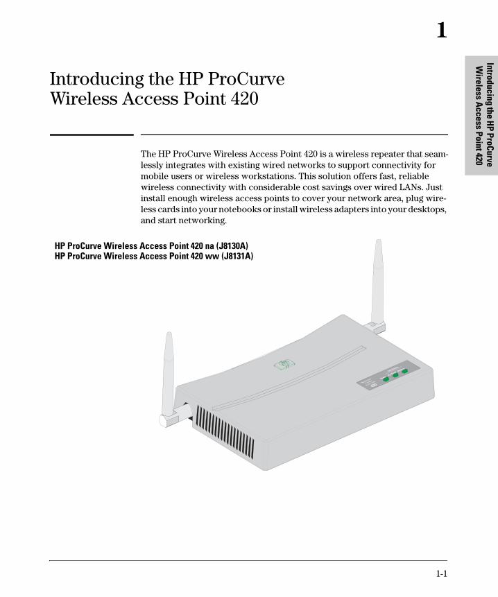
The HP ProCurve Wireless Access Point 420 is a wireless repeater that seamlessly integrates with existing wired networks to support connectivity for mobile users or wireless workstations. This solution offers fast, reliable wireless connectivity with considerable cost savings over wired LANs. Just install enough wireless access points to cover your network area, plug wire-less cards into your notebooks or install wireless adapters into your desktops, and start networking.
hp procurve
wireless
access point
420
Link/Ac tivity
Wireless
10/100-TX
Power
HP ProCurve Wireless Access Point 420 na (J8130A) HP ProCurve Wireless Access Point 420 ww (J8131A)
1-1

Intr
oduc
ing
the
HP P
roCu
rve
Wir
eles
s A
cces
s Po
int 4
20
Introducing the HP ProCurve Wireless Access Point 420
Throughout this manual, this access point will be abbreviated as the Access Point 420.
The Access Point 420 has one 10/100Base-TX RJ-45 port. This port also supports Power over Ethernet (PoE) based on the IEEE 802.3af standard. The access point supports wireless connectivity at speeds up to 54 Mbps based on the IEEE 802.11g standard.
This access point is designed to be used primarily for connecting wireless clients to an enterprise network. This access point allows wireless clients to connect directly to each other, or to connect to other computers or network resources located on the wired network.
This chapter describes your HP Access Point 420 including:
■ Top and back of the access point ■ Access point features
1-2
Introducing the HP ProCurve Wireless Access Point 420 Top of the Access Point
Wireless A
ccess Point 420 Introducing the H
P ProCurve
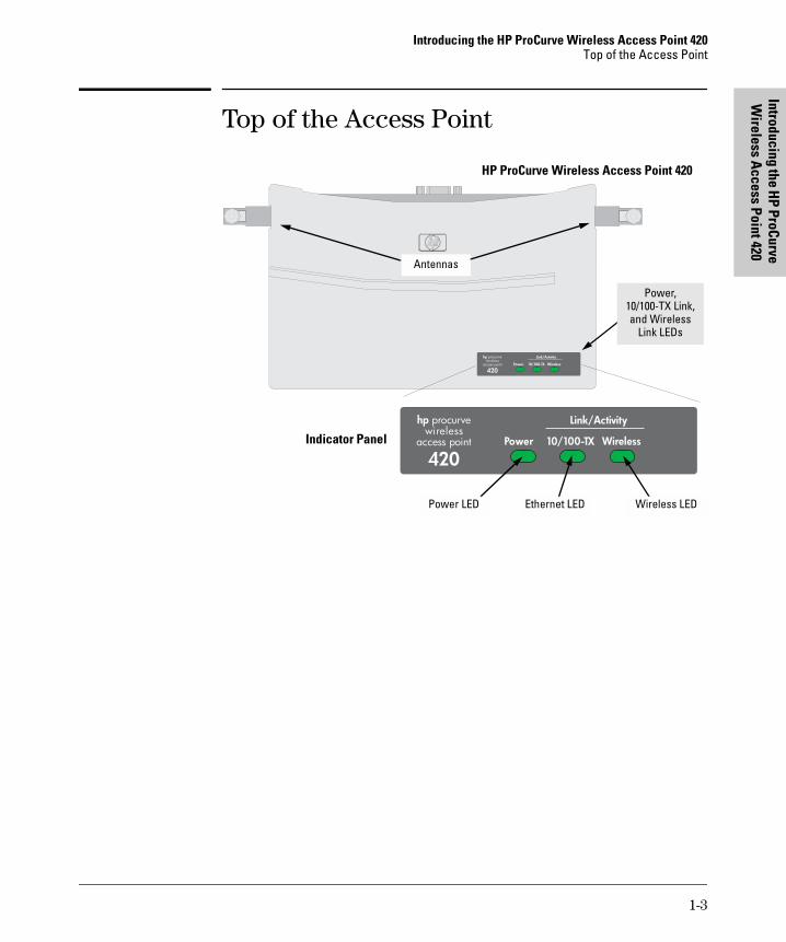
Top of the Access Point
HP ProCurve Wireless Access Point 420
hp procurve wireless
access point
420
Link/Activity
Wireless10 /10 0 -TXPo w e r
Power, 10/100-TX Link, and Wireless
Link LEDs
Antennas
Indicator Panel hp procurve
wireless access point
420
Link/Activity
Wireless10/100-TXPower
Power LED Ethernet LED Wireless LED
1-3
Introducing the HP ProCurve Wireless Access Point 420 Top of the Access Point
Intr
oduc
ing
the
HP P
roCu
rve
Wir
eles
s A
cces
s Po
int 4
20
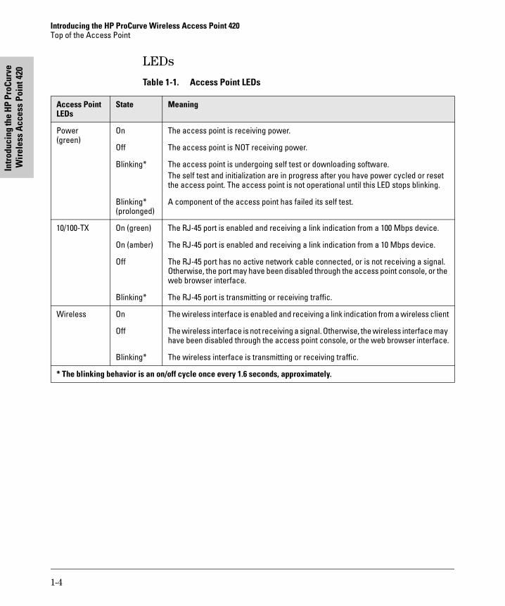
LEDsTable 1-1. Access Point LEDs
Access Point LEDs
State Meaning
Power (green)
On
Off
Blinking*
Blinking* (prolonged)
The access point is receiving power.
The access point is NOT receiving power.
The access point is undergoing self test or downloading software. The self test and initialization are in progress after you have power cycled or reset the access point. The access point is not operational until this LED stops blinking.
A component of the access point has failed its self test.
10/100-TX On (green)
On (amber)
Off
Blinking*
The RJ-45 port is enabled and receiving a link indication from a 100 Mbps device.
The RJ-45 port is enabled and receiving a link indication from a 10 Mbps device.
The RJ-45 port has no active network cable connected, or is not receiving a signal. Otherwise, the port may have been disabled through the access point console, or the web browser interface.
The RJ-45 port is transmitting or receiving traffic.
Wireless On
Off
Blinking*
The wireless interface is enabled and receiving a link indication from a wireless client
The wireless interface is not receiving a signal. Otherwise, the wireless interface may have been disabled through the access point console, or the web browser interface.
The wireless interface is transmitting or receiving traffic.
* The blinking behavior is an on/off cycle once every 1.6 seconds, approximately.
1-4
Introducing the HP ProCurve Wireless Access Point 420 Back of the Access Point
Wireless A
ccess Point 420 Introducing the H
P ProCurve
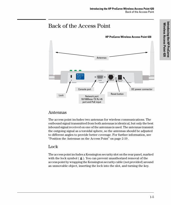
Back of the Access Point
HP ProCurve Wireless Access Point 420
Reset button
Antennas
Network port 10/100Base-TX RJ-45
port and PoE input
DC power connector Console port
Lock
Antennas
The access point includes two antennas for wireless communications. The outbound signal transmitted from both antennas is identical, but only the best inbound signal received on one of the antennas is used. The antennas transmit the outgoing signal as a toroidal sphere, so the antennas should be adjusted to different angles to provide better coverage. For further information, see “Position the Antennas on the Access Point” on page 2-10 .
Lock
The access point includes a Kensington security slot on the rear panel, marked with the lock symbol ( ). You can prevent unauthorized removal of the access point by wrapping the Kensington security cable (not provided) around an unmovable object, inserting the lock into the slot, and turning the key.
1-5
Intr
oduc
ing
the
HP P
roCu
rve
Wir
eles
s A
cces
s Po
int 4
20
Introducing the HP ProCurve Wireless Access Point 420 Back of the Access Point
Console Port
This port connects a console to the access point using a serial cable. This connection is described under “Connect a Console to the Access Point” in chapter 2, “Installing the Access Point 420”. The console can be a PC or workstation running a VT-100 terminal emulator, or a VT-100 terminal.
Network Port
The access point includes one 10/100Base-TX port. This port uses MDI (i.e., internal straight-through) pin configuration. You can therefore use straight-through twisted-pair cable to connect this port to most network interconnection devices such as a switch or router that provide MDI-X ports. However, if you need to connect the access point to a workstation or other device that only has MDI ports, then use crossover twisted-pair cable.
Ports on most HP switches have the “HP Auto MDIX” feature, which means
that you can use either straight-through or crossover twisted-pair cables to
connect the access point to these switches.
Refer to the following section for information on supplying power to the access point through its RJ-45 port from a network device, such as a switch, that provides Power over Ethernet (PoE).
Power Connector
The Access Point 420 does not have a power switch; it is powered on when connected to the AC power adapter, and the power adapter is connected to an active AC power source. The access point's power adapter automatically adjusts to any voltage between 100--240 volts and either 50 or 60 Hz. There are no voltage range settings required.
C a u t i o n Use only the AC power adapter supplied with the access point. Use of other adapters, including adapters that came with other HP network products, may result in damage to the equipment.
The access point may also receive Power over Ethernet (PoE) from a switch or other network device that supplies power over the network cable based on the IEEE 802.3af standard.
Note that if the access point is connected to a PoE source device and also connected to a local power source through the AC power adapter, PoE will be disabled.
1-6
Introducing the HP ProCurve Wireless Access Point 420 Back of the Access Point
Wireless A
ccess Point 420 Introducing the H
P ProCurve
Reset Button
This button is used to reset the hardware or restore the factory defaults:
■ To Reset the Access Point While it is Powered On – This action clears any temporary error conditions that may have occurred and executes the access point self test.
■ To Restore Factory Default Configuration – When the Reset button is pressed for more than five seconds, any configuration changes you may have made through the access point console or the web browser interface are removed, and the factory default configuration is restored to the access point. For the specific method to restore the factory default configuration, see “Restoring the Factory Default Configuration” in chapter 4, “Troubleshooting” of this manual.
1-7
Introducing the HP ProCurve Wireless Access Point 420 Access Point Features
Intr
oduc
ing
the
HP P
roCu
rve
Wir
eles
s A
cces
s Po
int 4
20
Access Point Features
The wireless features of the Access Point 420 include:
■ supports up to 128 wireless clients
■ IEEE 802.11g Compliant – interoperable with multiple vendors
■ precise control over signal transmission power and data rate
■ advanced security through 64/128/152-bit WEP encryption, Wi-Fi Protected Access (WPA), IEEE 802.1x, remote authentication via a RADIUS server, and MAC address filtering features to protect your sensitive data and authenticate only authorized users to your network
■ remote logging of system messages
■ time synchronization via SNTP server for message logs
■ auto channel selection – simplifies access deployment by testing all available channels and selecting the best channel based on signal-to-noise ratio
■ international country configuration – select the appropriate country and the access point automatically configures radio operation to match regulatory requirements (model J8131A only)
The other basic features of the Access Point 420 include:
■ one 10/100Base-TX RJ-45 port
■ supports Power over Ethernet based on the IEEE 802.3af standard
■ full-duplex operation for the 10/100 RJ-45 port
■ easy management of the access point through several available interfaces:
• console interface—a full featured, easy to use, VT-100 terminal interface that is especially good for out-of-band access point management or for Telnet access to the access point
• web browser interface—an easy to use built-in graphical interface that can be accessed from common web browsers
■ support for up to 64 IEEE 802.1Q-compliant VLANs (as specified for each client in the RADIUS server) so that wireless clients can join the appropriate logical grouping for the network user's needs
■ support for many advanced features to enhance network performance— for a description, see the Management and Configuration Guide, which is on the Documentation CD-ROM that is included with your access point.
■ download of new access point software for product enhancements or software updates
■ dual flash images – enables auto-recovery upon unsuccessful download
1-8
Access Point 420 Installing the
2
Installing the Access Point 420
The HP Access Point 420 is easy to install. It comes with an accessory kit that includes a bracket for mounting the access point on a wall. The bracket is designed to allow mounting the access point in a variety of locations and orientations.
This chapter shows you how to install your Access Point 420.
Included Parts The Access Point 420 has the following components shipped with it:
■ HP ProCurve Wireless Access Point 420 Installation and Getting
Started Guide (J8130A-90001), this manual
■ HP ProCurve Product Documentation CD-ROM
(contains PDF file copies of the documentation for the Access Point 420, including the Management and Configuration Guide)
■ Customer Support/Warranty booklet
■ Accessory kit (5069-5700) • four 5/8-inch number 12 wood screws to attach the access point to a
wall • four plastic wall plugs for mounting on a brick or concrete wall • four rubber feet
■ Antenna (5092-0723)
■ Mounting bracket (5092-0711)
■ AC power adapter (5092-0728)
■ AC power cord, one of the following:
United States/Canada/Mexico 8120-0740 Continental Europe 8121-0731 United Kingdom/Hong Kong/Singapore 8121-0739 Australia/New Zealand 8121-0730 Japan 8121-0736 China 8121-0742 Denmark 8121-0733 Switzerland 8121-0738
2-1
Installing the Access Point 420 Installation Procedures
Inst
allin
g th
e A
cces
s Po
int 4
20
Installation Procedures
Summary
Follow these easy steps to install your access point. The rest of this chapter provides details on these steps.
1. Prepare the installation site (page 2-4). Make sure that the physical environment into which you will be installing the access point is properly prepared, including having the correct network cabling ready to connect to the access point and having an appropriate location for the access point. Please see page 2-3 for some installation precautions.
2. Verify that the access point passes self test (page 2-5). This is a simple process of plugging the access point into a power source, or connecting it to a switch that provides Power over Ethernet, and observing that the LEDs on the access point’s top panel indicate correct access point operation.
3. Mount the access point (page 2-7). The Access Point 420 can be mounted on a wall, or on a horizontal surface.
4. Connect power to the access point (page 2-9). Once the access point is mounted, plug it into a nearby main power source, or connect it to a switch that provides Power over Ethernet.
5. Connect to the network (page 2-10). Using the appropriate network cable, connect the access point to a network connection point, such as a switch. The network connection can also be used to provide power to the access point through its PoE feature.
6. Position the antennas on the access point (page 2-10). Position each antenna along a different axis to enhance signal coverage.
7. Connect a console to the access point (optional—page 2-11). You may wish to modify the access point’s configuration, for example, to configure an IP address so it can be managed using a web browser or through a Telnet session. Configuration changes can be made easily by using a console cable to connect a PC to the access point’s console port.
At this point, your access point is fully installed. See the rest of this chapter if you need more detailed information on any of these installation steps.
2-2

Installing the Access Point 420 Installation Procedures
Access Point 420 Installing the
Installation Precautions:
Follow these precautions when installing your HP Access Point 420:
C a u t i o n s ■ Make sure that the power source circuits are properly grounded, then use the power adapter supplied with the access point to connect it to the power source.
■ You can alternatively power the access point through a network connection to a switch or other network connection device that provides Power over Ethernet. However, note that if the access point is connected to a power source using its AC power adapter, Power over Ethernet is disabled.
■ Use only the AC power adapter supplied with the access point. Use of other adapters, including adapters that came with other HP network products, may result in damage to the equipment.
■ When using the acess point's AC power adapter, note that the AC outlet should be near the access point and should be easily accessible in case the access point must be powered off.
■ Ensure that the access point does not overload the power circuits, wiring, and over-current protection. To determine the possibility of overloading the supply circuits, add together the ampere ratings of all devices installed on the same circuit as the access point and compare the total with the rating limit for the circuit. The maximum ampere ratings are usually printed on devices near the AC power connectors.
■ Do not install the access point in an environment where the operating ambient temperature might exceed 40°C (104°F).
■ Make sure the air flow around the sides of the access point is not restricted.
2-3
Installing the Access Point 420 Installation Procedures
Inst
allin
g th
e A
cces
s Po
int 4
20
1. Prepare the Installation Site
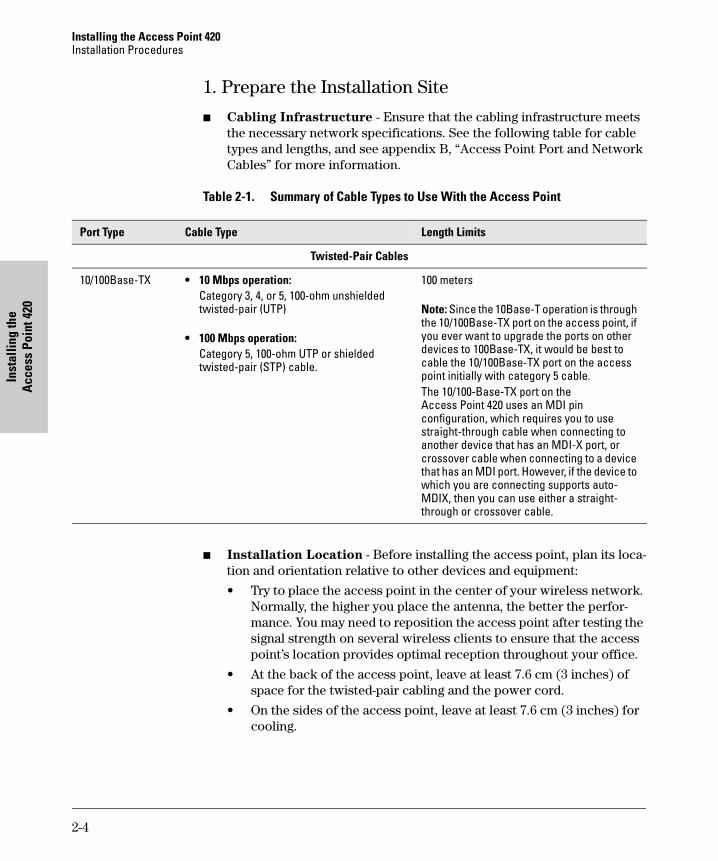
■ Cabling Infrastructure - Ensure that the cabling infrastructure meets the necessary network specifications. See the following table for cable types and lengths, and see appendix B, “Access Point Port and Network Cables” for more information.
Table 2-1. Summary of Cable Types to Use With the Access Point
Port Type Cable Type Length Limits
Twisted-Pair Cables
10/100Base-TX • 10 Mbps operation: Category 3, 4, or 5, 100-ohm unshielded twisted-pair (UTP)
• 100 Mbps operation: Category 5, 100-ohm UTP or shielded twisted-pair (STP) cable.
100 meters
Note: Since the 10Base-T operation is through the 10/100Base-TX port on the access point, ifyou ever want to upgrade the ports on otherdevices to 100Base-TX, it would be best tocable the 10/100Base-TX port on the accesspoint initially with category 5 cable.The 10/100-Base-TX port on the Access Point 420 uses an MDI pin configuration, which requires you to usestraight-through cable when connecting toanother device that has an MDI-X port, orcrossover cable when connecting to a devicethat has an MDI port. However, if the device towhich you are connecting supports auto-MDIX, then you can use either a straight-through or crossover cable.
■ Installation Location - Before installing the access point, plan its location and orientation relative to other devices and equipment:
• Try to place the access point in the center of your wireless network. Normally, the higher you place the antenna, the better the performance. You may need to reposition the access point after testing the signal strength on several wireless clients to ensure that the access point’s location provides optimal reception throughout your office.
• At the back of the access point, leave at least 7.6 cm (3 inches) of space for the twisted-pair cabling and the power cord.
• On the sides of the access point, leave at least 7.6 cm (3 inches) for cooling.
2-4
Installing the Access Point 420 Installation Procedures
Access Point 420 Installing the
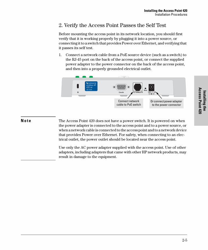
2. Verify the Access Point Passes the Self Test
Before mounting the access point in its network location, you should first verify that it is working properly by plugging it into a power source, or connecting it to a switch that provides Power over Ethernet, and verifying that it passes its self test.
1. Connect a network cable from a PoE source device (such as a switch) to the RJ-45 port on the back of the access point, or connect the supplied power adapter to the power connector on the back of the access point, and then into a properly grounded electrical outlet.
Or connect power adapter to the power connector
Connect network cable to PoE switch
N o t e The Access Point 420 does not have a power switch. It is powered on when the power adapter is connected to the access point and to a power source, or when a network cable is connected to the access point and to a network device that provides Power over Ethernet. For safety, when connecting to an electrical outlet, the power outlet should be located near the access point.
Use only the AC power adapter supplied with the access point. Use of other adapters, including adapters that came with other HP network products, may result in damage to the equipment.
2-5
Installing the Access Point 420 Installation Procedures
Inst
allin
g th
e A
cces
s Po
int 4
20
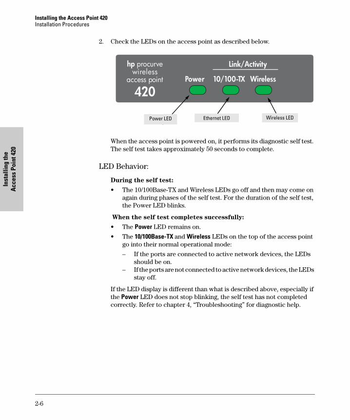
2. Check the LEDs on the access point as described below.
hp procurve wireless
access point
420
Link/Activity
Wireless10/100-TXPower
Wireless LEDEthernet LEDPower LED
When the access point is powered on, it performs its diagnostic self test. The self test takes approximately 50 seconds to complete.
LED Behavior:
During the self test:
• The 10/100Base-TX and Wireless LEDs go off and then may come on again during phases of the self test. For the duration of the self test, the Power LED blinks.
When the self test completes successfully:
• The Power LED remains on.
• The 10/100Base-TX and Wireless LEDs on the top of the access point go into their normal operational mode:
– If the ports are connected to active network devices, the LEDs should be on.
– If the ports are not connected to active network devices, the LEDs stay off.
If the LED display is different than what is described above, especially if the Power LED does not stop blinking, the self test has not completed correctly. Refer to chapter 4, “Troubleshooting” for diagnostic help.
2-6
Installing the Access Point 420 Installation Procedures
Access Point 420 Installing the
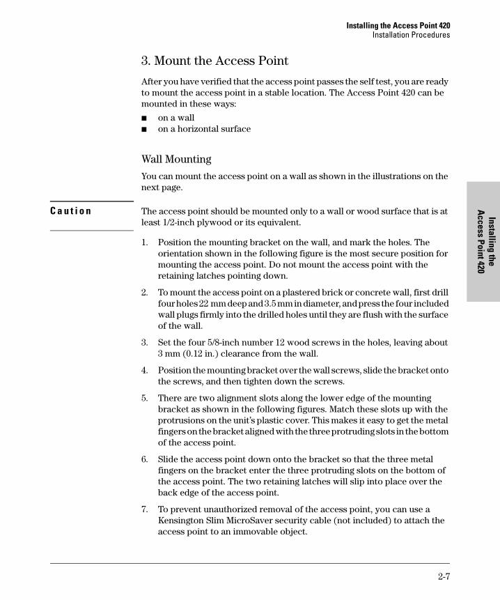
3. Mount the Access Point
After you have verified that the access point passes the self test, you are ready to mount the access point in a stable location. The Access Point 420 can be mounted in these ways:
■ on a wall ■ on a horizontal surface
Wall Mounting
You can mount the access point on a wall as shown in the illustrations on the next page.
C a u t i o n The access point should be mounted only to a wall or wood surface that is at least 1/2-inch plywood or its equivalent.
1. Position the mounting bracket on the wall, and mark the holes. The orientation shown in the following figure is the most secure position for mounting the access point. Do not mount the access point with the retaining latches pointing down.
2. To mount the access point on a plastered brick or concrete wall, first drill four holes 22 mm deep and 3.5 mm in diameter, and press the four included wall plugs firmly into the drilled holes until they are flush with the surface of the wall.
3. Set the four 5/8-inch number 12 wood screws in the holes, leaving about 3 mm (0.12 in.) clearance from the wall.
4. Position the mounting bracket over the wall screws, slide the bracket onto the screws, and then tighten down the screws.
5. There are two alignment slots along the lower edge of the mounting bracket as shown in the following figures. Match these slots up with the protrusions on the unit’s plastic cover. This makes it easy to get the metal fingers on the bracket aligned with the three protruding slots in the bottom of the access point.
6. Slide the access point down onto the bracket so that the three metal fingers on the bracket enter the three protruding slots on the bottom of the access point. The two retaining latches will slip into place over the back edge of the access point.
7. To prevent unauthorized removal of the access point, you can use a Kensington Slim MicroSaver security cable (not included) to attach the access point to an immovable object.
2-7
Installing the Access Point 420 Installation Procedures
Inst
allin
g th
e A
cces
s Po
int 4
20
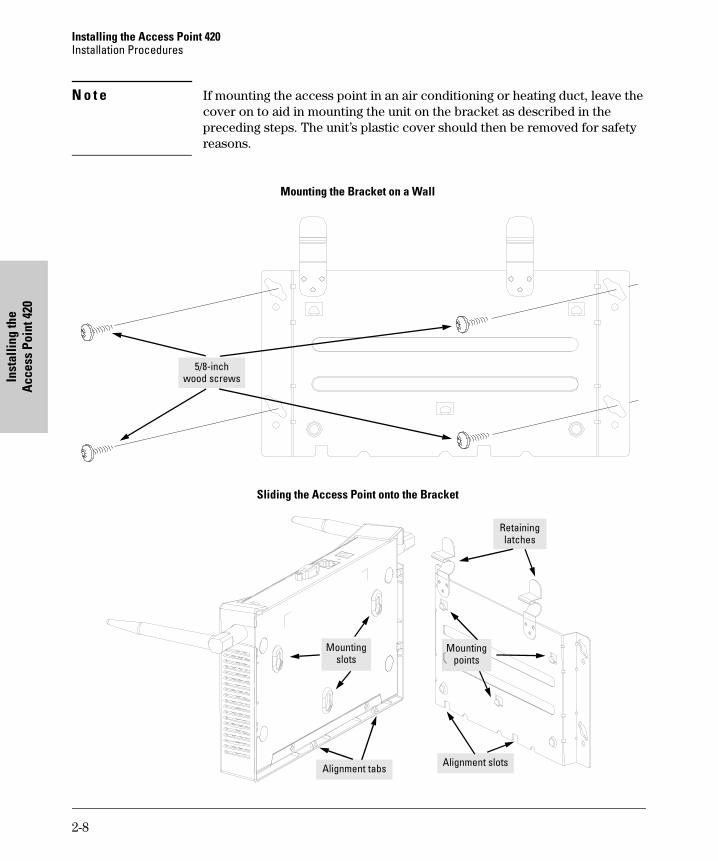
N o t e If mounting the access point in an air conditioning or heating duct, leave the cover on to aid in mounting the unit on the bracket as described in the preceding steps. The unit’s plastic cover should then be removed for safety reasons.
Mounting the Bracket on a Wall
5/8-inch wood screws
Sliding the Access Point onto the Bracket
Alignment slots
Mounting points
Retaining latches
Mounting slots
Alignment tabs
2-8
Installing the Access Point 420 Installation Procedures
Access Point 420 Installing the
Horizontal Surface Mounting
Place the access point on a table or other horizontal surface. The access point accessory kit provides rubber feet that can be used to help keep the access point from sliding on the surface.
Attach the rubber feet to the four corners on the bottom of the access point within the embossed lines. Use a sturdy surface in an uncluttered area. You may want to secure the networking cable and access point’s power cord to the table leg or other part of the surface structure to help prevent tripping over the cords.
C a u t i o n Make sure the air flow is not restricted around the sides of the access point.
4. Connect the Access Point to a Power Source 1. Plug the included power adapter into the access point’s power connector
and into a nearby AC power source.
Or, alternatively, connect the Ethernet port on the access point to a switch or other network device that provides Power over Ethernet.
2. Re-check the LEDs during self test. See “LED Behavior” on page 2-6.
2-9
Installing the Access Point 420 Installation Procedures
Inst
allin
g th
e A
cces
s Po
int 4
20
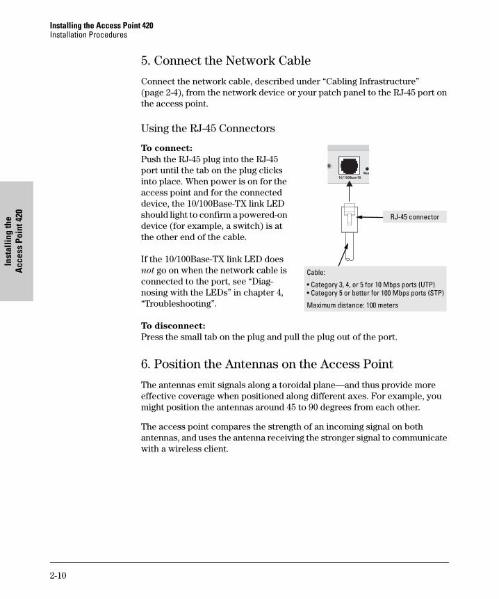
5. Connect the Network Cable
Connect the network cable, described under “Cabling Infrastructure” (page 2-4), from the network device or your patch panel to the RJ-45 port on the access point.
Using the RJ-45 Connectors
To connect: Push the RJ-45 plug into the RJ-45 port until the tab on the plug clicks into place. When power is on for the access point and for the connected device, the 10/100Base-TX link LED should light to confirm a powered-on RJ-45 connector
Cable:
• Category 3, 4, or 5 for 10 Mbps ports (UTP) • Category 5 or better for 100 Mbps ports (STP)
Maximum distance: 100 meters
device (for example, a switch) is at the other end of the cable.
If the 10/100Base-TX link LED does not go on when the network cable is connected to the port, see “Diagnosing with the LEDs” in chapter 4, “Troubleshooting”.
To disconnect: Press the small tab on the plug and pull the plug out of the port.
6. Position the Antennas on the Access Point
The antennas emit signals along a toroidal plane—and thus provide more effective coverage when positioned along different axes. For example, you might position the antennas around 45 to 90 degrees from each other.
The access point compares the strength of an incoming signal on both antennas, and uses the antenna receiving the stronger signal to communicate with a wireless client.
2-10
Installing the Access Point 420 Installation Procedures
Access Point 420 Installing the
7. (Optional) Connect a Console to the Access Point 420 The Access Point 420 has a full-featured, easy to use console interface for performing access point management tasks, including the following:
■ modify the access point’s configuration to optimize access point performance, enhance network traffic control, and improve network security
■ download new software to the access point
■ add a password to control access to the access point from the console, web browser interface, and network management stations
The console can be accessed through these methods:
■ Out-of-Band: Use a serial cable for connecting a PC or VT-100 terminal to be used as a console directly to the access point.
■ In-Band: Access the console using Telnet from a PC on the network, and a VT-100 terminal emulator. This method requires that you first configure the access point with an IP address and subnet mask by using either out-of-band console access or through DHCP. For more information on IP addressing and on starting a Telnet session, see chapter 3, “Getting Started With Access Point Configuration”, and the Management and Configura
tion Guide, which is on the Documentation CD-ROM that came with your access point.
The Access Point 420 can simultaneously support one out-of-band console session through the Console Port and four in-band Telnet console sessions.
N o t e For information on using the web browser interface to configure the access point, refer to the Management and Configuration Guide.
Terminal Configuration
To connect a console to the access point, configure the PC terminal emulator as a DEC VT-100 (ANSI) terminal or use a VT-100 terminal, and configure either one to operate with these settings:
• 9600 baud
• 8 data bits, 1 stop bit, no parity, and flow control set to None
• For the Windows Terminal program, also disable (uncheck) the “Use Function, Arrow, and Ctrl Keys for Windows” option
• For the Hilgraeve HyperTerminal program, select the “Terminal keys” option for the “Function, arrow, and ctrl keys act as” parameter
You can only attach to the console using these configuration settings.
2-11
Installing the Access Point 420Installation Procedures
Inst
allin
g th
e A
cces
sPo
int4
20
Direct Console Access
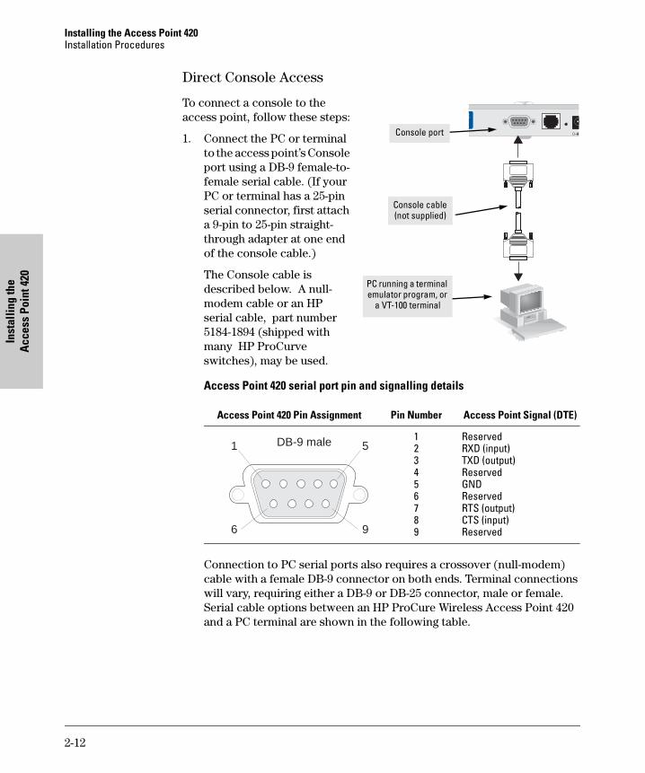
To connect a console to the access point, follow these steps:
1. Connect the PC or terminal to the access point’s Console port using a DB-9 female-to-female serial cable. (If your PC or terminal has a 25-pin serial connector, first attach a 9-pin to 25-pin straight-through adapter at one end of the console cable.)
The Console cable is described below. A null-modem cable or an HP serial cable, part number 5184-1894 (shipped with many HP ProCurve switches), may be used.
Access Point 420 serial port pin and signalling details
Connection to PC serial ports also requires a crossover (null-modem) cable with a female DB-9 connector on both ends. Terminal connections will vary, requiring either a DB-9 or DB-25 connector, male or female. Serial cable options between an HP ProCure Wireless Access Point 420 and a PC terminal are shown in the following table.
Access Point 420 Pin Assignment Pin Number Access Point Signal (DTE)
123456789
ReservedRXD (input)TXD (output)ReservedGNDReservedRTS (output)CTS (input)Reserved
Console port
Console cable (not supplied)
PC running a terminal emulator program, or
a VT-100 terminal
DB-9 male 5
9
1
6
2-12

Installing the Access Point 420 Installation Procedures
Access Point 420 Installing the
Note: As indicated in the following table, some of the wires should not be connected. If you do connect the wires that are labeled “Reserved”, you might get unexpected results with some terminals.
Serial interface signal directions
DB-9 (DTE) DB9 (DTE) DB-9 (DTE) DB-25 (DTE) Access Point 420 Terminal or PC Access Point 420 Terminal or PC
GND GND
1 Reserved 1 1 Reserved 8 2 2 2 3 3 3 3 2 4 Reserved 4 4 Reserved 20 5 5 5 7 6 Reserved 6 6 Reserved 6 7 7 7 4 8 8 8 5 9 Reserved 9 9 Reserved 22
2. Turn on the terminal or PC’s power and, if using a PC, start the PC terminal program.
3. Enter admin at the Username: prompt, and press the [Enter] key at the Password prompt. You will then see the access point console command (CLI) prompt, for example:
HP ProCurve Wireless Access Point 420#
If you want to continue with console management of the access point at this time, see chapter 3, “Getting Started With Access Point Configuration” for some basic configuration steps. For more detailed information, refer to the Management and Configuration Guide, which is on the Documentation CD-ROM that came with your access point.
2-13
Installing the Access Point 420 Sample Network Topologies
Inst
allin
g th
e A
cces
s Po
int 4
20
Sample Network Topologies
This section shows you a few sample network topologies in which the Access Point 420 is implemented. The wireless solution supports a stand-alone wireless network configuration as well as an integrated configuration with wired Ethernet LANs. Wireless network cards, adapters, and access points can be configured as:
■ ad hoc for departmental or SOHO LANs ■ infrastructure for wireless LANs ■ infrastructure wireless LAN for roaming wireless PCs
For more topology information, see the HP network products World Wide Web site, http://www.hp.com/go/hpprocurve.
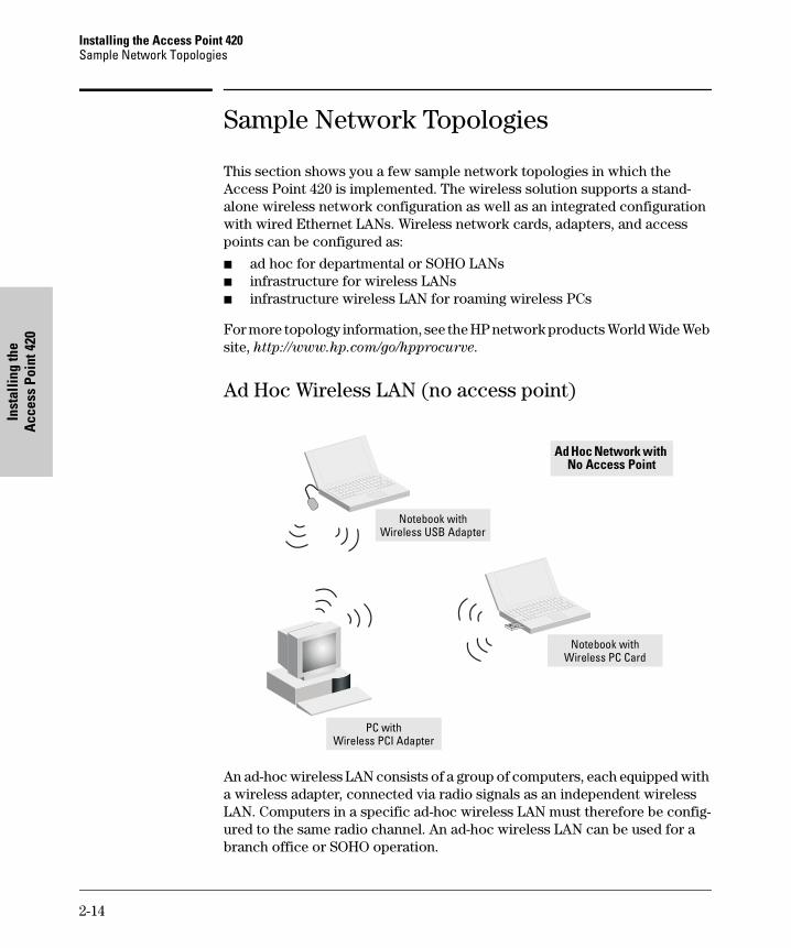
Ad Hoc Wireless LAN (no access point)
Notebook with Wireless USB Adapter
Notebook with Wireless PC Card
Ad Hoc Network with No Access Point
PC with Wireless PCI Adapter
An ad-hoc wireless LAN consists of a group of computers, each equipped with a wireless adapter, connected via radio signals as an independent wireless LAN. Computers in a specific ad-hoc wireless LAN must therefore be configured to the same radio channel. An ad-hoc wireless LAN can be used for a branch office or SOHO operation.
2-14
Installing the Access Point 420Sample Network Topologies
Installing the A
ccessPoint420
Infrastructure Wireless LAN
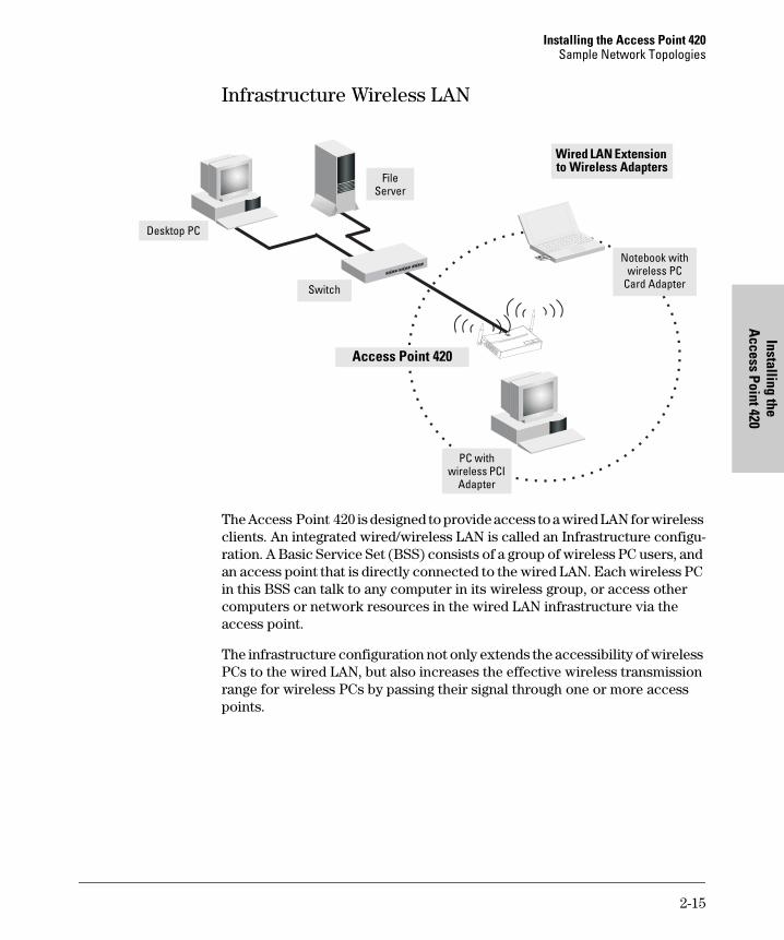
The Access Point 420 is designed to provide access to a wired LAN for wireless clients. An integrated wired/wireless LAN is called an Infrastructure configu-ration. A Basic Service Set (BSS) consists of a group of wireless PC users, and an access point that is directly connected to the wired LAN. Each wireless PC in this BSS can talk to any computer in its wireless group, or access other computers or network resources in the wired LAN infrastructure via the access point.
The infrastructure configuration not only extends the accessibility of wireless PCs to the wired LAN, but also increases the effective wireless transmission range for wireless PCs by passing their signal through one or more access points.
Desktop PC
Access Point 420
FileServer
Switch
PC with wireless PCI
Adapter
Notebook with wireless PC
Card Adapter
Wired LAN Extension to Wireless Adapters
2-15
Installing the Access Point 420Sample Network Topologies
Inst
allin
g th
e A
cces
sPo
int4
20
Infrastructure Wireless LAN for Roaming Wireless PCs
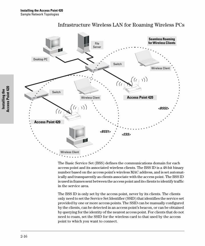
The Basic Service Set (BSS) defines the communications domain for each access point and its associated wireless clients. The BSS ID is a 48-bit binary number based on the access point’s wireless MAC address, and is set automat-ically and transparently as clients associate with the access point. The BSS ID is used in frames sent between the access point and its clients to identify traffic in the service area.
The BSS ID is only set by the access point, never by its clients. The clients only need to set the Service Set Identifier (SSID) that identifies the service set provided by one or more access points. The SSID can be manually configured by the clients, can be detected in an access point’s beacon, or can be obtained by querying for the identity of the nearest access point. For clients that do not need to roam, set the SSID for the wireless card to that used by the access point to which you want to connect.
Access Point 420
<BSS1>
Desktop PC
Access Point 420
FileServer
Switch
Switch
Wireless Client
Wireless Client
Wireless Client
<BSS2>
<ESS>
Seamless Roaming for Wireless Clients
2-16

Installing the Access Point 420 Sample Network Topologies
Access Point 420 Installing the
A wireless infrastructure can also support roaming for mobile workers. More than one access point can be configured to create an Extended Service Set (ESS). By placing the access points so that a continuous coverage area is created, wireless users within this ESS can roam freely. All HP wireless network cards, adapters, and access points within a specific ESS must be configured with the same SSID.
2-17

Installing the Access Point 420 Sample Network Topologies
Inst
allin
g th
e A
cces
s Po
int 4
20
2-18
Point Configuration G
etting Started With A
ccess
3
Getting Started With Access Point Configuration
This chapter is a guide for using the access point’s console to quickly assign an Internet Protocol (IP) address and subnet mask to the access point, set a manager password, and, optionally, configure other basic features.
For more information on using the access point’s console and the web browser interface, please see the Management and Configuration Guide, which is on the Documentation CD-ROM that came with your access point.
Recommended Minimal Configuration
In the factory default configuration, the access point is configured as a DHCP client. If the access point fails to obtain an IP address from the DHCP server, its IP address defaults to 192.168.1.1. If this address is not compatible with your network, then the access point can only be managed through a direct console connection. To manage the access point through in-band (networked) access, you should configure the access point with an IP address and subnet mask compatible with your network. Also, you should configure a manager password to control access privileges for the console and web browser interface. Other parameters can be left at their default settings or you can configure them with values you enter.
C a u t i o n The country code for the HP ProCurve Wireless Access Point 420 na (J8130A) sold in the United States and Canada is fixed in the firmware and cannot be changed. This means that only radio channels 1-11 are available for this model.
The country code for the HP ProCurve Wireless Access Point 420 ww (J8131A) sold in other countries is not set, and must be configured before you can enable radio communications for the access point. Setting the country code enables only those radio channels permitted for wireless networks in the specified country. Please refer to step 10 on page 3-4 for information on setting the country code.
Note that once you have set the country code, it can only be changed by
restoring the factory default settings as described under “Restoring the
Factory Default Configuration” on page 4-8.
3-1
Getting Started With Access Point Configuration
Get
ting
Star
ted
With
Acc
ess
Poin
t Con
figur
atio
n
Many other features can be configured through the access point’s console interface to optimize the access point’s performance, to enhance your control of the network traffic, and to improve network security. Once an IP address has been configured on the access point, these features can be accessed more conveniently through a remote Telnet session or through the access point’s web browser interface.
For more information on IP addressing, refer to “Configuring IP Settings” in the Management and Configuration Guide.
N o t e By default, the access point is configured to acquire an IP address configuration from a DHCP server. To use DHCP instead of the manual method described in this chapter, see “Configuring IP Settings” in the Management
and Configuration Guide, which is on the Documentation CD-ROM that came with your access point.
Using the Command Line Interface The quickest and easiest way to minimally configure the access point for management and password protection in your network is to use a direct console connection to the access point, start a console session, and access the command line interface (CLI).
1. Using the method described in the preceding chapter, connect a terminal device to the access point, and press [Enter] to initiate the console connection.
2. Type admin for the default user name. The default password is null, so just press [Enter] at the password prompt. The CLI prompt appears displaying the access point’s model number.
Username: adminPassword:HP ProCurve Access Point 420#
3. Type configure to enter global configuration mode.
HP ProCurve Access Point 420#configureEnter configuration commands, one per line. End with CTRL/ZHP ProCurve Access Point 420(config)#
4. Type username username to create a user name for the manager, where username can consist of 3 to 16 alphanumeric characters and is case sensitive. (Note that only one user name is allowed for the access point.)
HP ProCurve Access Point 420(config)#username adminHP ProCurve Access Point 420(config)#
3-2
Getting Started With Access Point Configuration Point Configuration
Getting Started W
ith Access
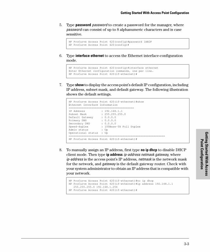
5. Type password password to create a password for the manager, where password can consist of up to 8 alphanumeric characters and is case sensitive.
HP ProCurve Access Point 420(config)#password 1AB2FHP ProCurve Access Point 420(config)#
6. Type interface ethernet to access the Ethernet interface-configuration mode.
HP ProCurve Access Point 420(config)#interface ethernetEnter Ethernet configuration commands, one per line.HP ProCurve Access Point 420(if-ethernet)#
7. Type show to display the access point’s default IP configuration, including IP address, subnet mask, and default gateway. The following illustration shows the default settings.
HP ProCurve Access Point 420(if-ethernet)#showEthernet Interface Information========================================IP Address : 192.168.1.1Subnet Mask : 255.255.255.0Default Gateway : 0.0.0.0Primary DNS : 0.0.0.0Secondary DNS : 0.0.0.0Speed-duplex : 100Base-TX Full DuplexAdmin status : UpOperational status : Up===========================================================HP ProCurve Access Point 420(if-ethernet)#
8. To manually assign an IP address, first type no ip dhcp to disable DHCP client mode. Then type ip address ip-address netmask gateway, where ip-address is the access point’s IP address, netmask is the network mask for the network, and gateway is the default gateway router. Check with your system administrator to obtain an IP address that is compatible with your network.
HP ProCurve Access Point 420(if-ethernet)#no ip dhcpHP ProCurve Access Point 420(if-ethernet)#ip address 192.168.1.1
255.255.255.0 192.168.1.254HP ProCurve Access Point 420(if-ethernet)#
3-3
Getting Started With Access Point Configuration
Get
ting
Star
ted
With
Acc
ess
Poin
t Con
figur
atio
n
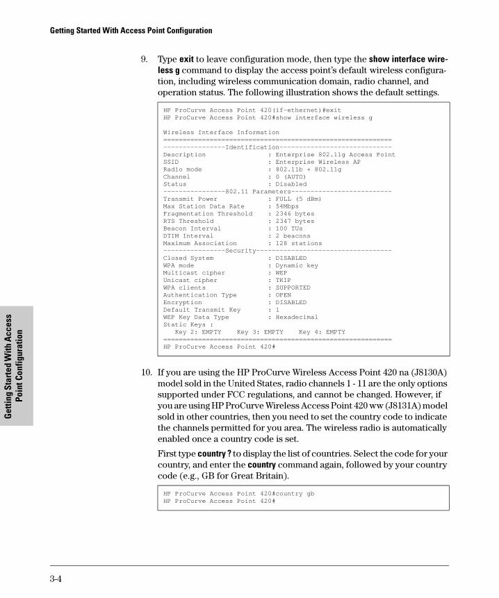
9. Type exit to leave configuration mode, then type the show interface wire-less g command to display the access point’s default wireless configuration, including wireless communication domain, radio channel, and operation status. The following illustration shows the default settings.
HP ProCurve Access Point 420(if-ethernet)#exitHP ProCurve Access Point 420#show interface wireless g
Wireless Interface Information===========================================================----------------Identification-----------------------------Description : Enterprise 802.11g Access PointSSID : Enterprise Wireless APRadio mode : 802.11b + 802.11gChannel : 0 (AUTO)Status : Disabled----------------802.11 Parameters--------------------------Transmit Power : FULL (5 dBm)Max Station Data Rate : 54MbpsFragmentation Threshold : 2346 bytesRTS Threshold : 2347 bytesBeacon Interval : 100 TUsDTIM Interval : 2 beaconsMaximum Association : 128 stations----------------Security-----------------------------------Closed System : DISABLEDWPA mode : Dynamic keyMulticast cipher : WEPUnicast cipher : TKIPWPA clients : SUPPORTEDAuthentication Type : OPENEncryption : DISABLEDDefault Transmit Key : 1WEP Key Data Type : HexadecimalStatic Keys :
Key 2: EMPTY Key 3: EMPTY Key 4: EMPTY===========================================================HP ProCurve Access Point 420#
10. If you are using the HP ProCurve Wireless Access Point 420 na (J8130A) model sold in the United States, radio channels 1 - 11 are the only options supported under FCC regulations, and cannot be changed. However, if you are using HP ProCurve Wireless Access Point 420 ww (J8131A) model sold in other countries, then you need to set the country code to indicate the channels permitted for you area. The wireless radio is automatically enabled once a country code is set.
First type country ? to display the list of countries. Select the code for your country, and enter the country command again, followed by your country code (e.g., GB for Great Britain).
HP ProCurve Access Point 420#country gbHP ProCurve Access Point 420#
3-4
Getting Started With Access Point Configuration Point Configuration
Getting Started W
ith Access
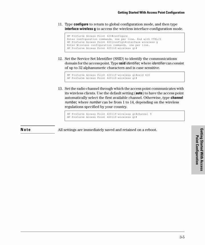
11. Type configure to return to global configuration mode, and then type interface wireless g to access the wireless interface-configuration mode.
HP ProCurve Access Point 420#configureEnter configuration commands, one per line. End with CTRL/ZHP ProCurve Access Point 420(config)#interface wireless gEnter Wireless configuration commands, one per line.HP ProCurve Access Point 420(if-wireless g)#
12. Set the Service Set Identifier (SSID) to identify the communications domain for the access point. Type ssid identifier, where identifier can consist of up to 32 alphanumeric characters and is case sensitive.
HP ProCurve Access Point 420(if-wireless g)#ssid 420HP ProCurve Access Point 420(if-wireless g)#
13. Set the radio channel through which the access point communicates with its wireless clients. Use the default setting (auto) to have the access point automatically select the first available channel. Otherwise, type channel number, where number can be from 1 to 14, depending on the wireless regulations specified by your country.
HP ProCurve Access Point 420(if-wireless g)#channel 9HP ProCurve Access Point 420(if-wireless g)#
N o t e All settings are immediately saved and retained on a reboot.
3-5
Getting Started With Access Point Configuration
Get
ting
Star
ted
With
Acc
ess
Poin
t Con
figur
atio
n
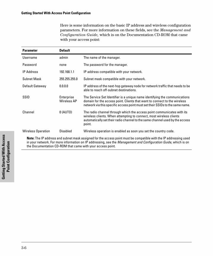
Here is some information on the basic IP address and wireless configuration parameters. For more information on these fields, see the Management and
Configuration Guide, which is on the Documentation CD-ROM that came with your access point:
Parameter Default
Username admin The name of the manager.
Password none The password for the manager.
IP Address 192.168.1.1 IP address compatible with your network.
Subnet Mask 255.255.255.0 Subnet mask compatible with your network.
Default Gateway 0.0.0.0 IP address of the next-hop gateway node for network traffic that needs to be able to reach off-subnet destinations.
SSID Enterprise The Service Set Identifier is a unique name identifying the communications Wireless AP domain for the access point. Clients that want to connect to the wireless
network via this specific access point must set their SSIDs to the same name.
Channel 0 (AUTO) The radio channel through which the access point communicates with its wireless clients. When attempting to connect, most wireless clients automatically set their radio channel to the same channel used by the access point.
Wireless Operation Disabled Wireless operation is enabled as soon you set the country code.
Note: The IP address and subnet mask assigned for the access point must be compatible with the IP addressing used in your network. For more information on IP addressing, see the Management and Configuration Guide, which is on the Documentation CD-ROM that came with your access point.
3-6
Getting Started With Access Point Configuration Point Configuration
Getting Started W
ith Access
Where to Go From Here
The above procedure, using the CLI, configured your access point with a manager password, IP address, and subnet mask. As a result, with the proper network connections, you can now manage the access point from a PC equipped with Telnet or a web browser interface. The above procedure also configured the Service Set Identifier (SSID), radio channel, and enabled wireless operation. Your wireless clients can now access the network by setting their SSID and radio channel to the same values used by the access point. Note that some wireless clients can be configured to scan all of the radio channels for an access point and the SSID.
Some basic information on managing your access point is included in the next section. For more information on the console and web browser interfaces, and all the features that can be configured on the Access Point 420, please see the Management and Configuration Guide, which is on the Documentation CD-ROM that came with your access point.
To Recover from a Lost Manager Password: If you cannot start a con-sole session because of a lost manager password, you can clear the password and user name by getting physical access to the access point and pressing and holding the Reset button for more than five seconds. However, note that this action resets all configuration settings to the factory defaults.
3-7
Getting Started With Access Point Configuration Using the IP Address for Remote Access Point Management
Get
ting
Star
ted
With
Acc
ess
Poin
t Con
figur
atio
n
Using the IP Address for Remote Access Point Management
With your Access Point 420, you can use the access point’s IP address to manage the access point from any PC that is on the same subnet as the access point. You can use either a Telnet session or a standard web browser to manage the access point.
Starting a Telnet Session
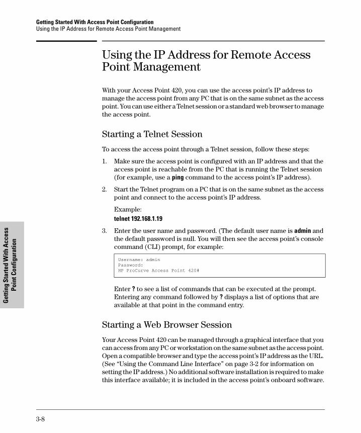
To access the access point through a Telnet session, follow these steps:
1. Make sure the access point is configured with an IP address and that the access point is reachable from the PC that is running the Telnet session (for example, use a ping command to the access point’s IP address).
2. Start the Telnet program on a PC that is on the same subnet as the access point and connect to the access point’s IP address.
Example: telnet 192.168.1.19
3. Enter the user name and password. (The default user name is admin and the default password is null. You will then see the access point’s console command (CLI) prompt, for example:
Username: adminPassword:HP ProCurve Access Point 420#
Enter ? to see a list of commands that can be executed at the prompt. Entering any command followed by ? displays a list of options that are available at that point in the command entry.
Starting a Web Browser Session
Your Access Point 420 can be managed through a graphical interface that you can access from any PC or workstation on the same subnet as the access point. Open a compatible browser and type the access point’s IP address as the URL. (See “Using the Command Line Interface” on page 3-2 for information on setting the IP address.) No additional software installation is required to make this interface available; it is included in the access point’s onboard software.
3-8
Getting Started With Access Point Configuration Using the IP Address for Remote Access Point Management
Point Configuration G
etting Started With A
ccess
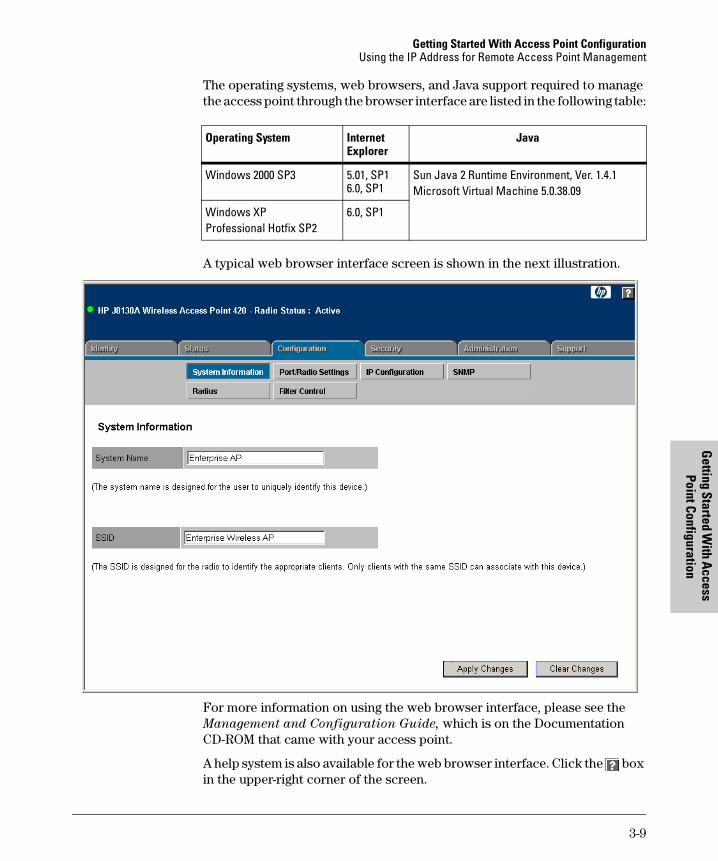
The operating systems, web browsers, and Java support required to manage the access point through the browser interface are listed in the following table:
Operating System Internet Explorer
Java
Windows 2000 SP3 5.01, SP1 6.0, SP1
Sun Java 2 Runtime Environment, Ver. 1.4.1 Microsoft Virtual Machine 5.0.38.09
Windows XP Professional Hotfix SP2
6.0, SP1
A typical web browser interface screen is shown in the next illustration.
For more information on using the web browser interface, please see the Management and Configuration Guide, which is on the Documentation CD-ROM that came with your access point.
A help system is also available for the web browser interface. Click the box in the upper-right corner of the screen.
3-9

Getting Started With Access Point Configuration Using the IP Address for Remote Access Point Management
Get
ting
Star
ted
With
Acc
ess
Poin
t Con
figur
atio
n
3-10
Troubleshooting
4
Troubleshooting
This chapter describes how to troubleshoot your HP ProCurve Wireless Access Point 420. Note that this document describes troubleshooting mostlyfrom a hardware perspective. You can perform more in-depth troubleshootingon the Access Point 420 using the software tools available with the access point, including the full-featured console interface and the built-in webbrowser interface.
This chapter describes the following:
■ basic troubleshooting tips (page 4-1)
■ diagnosing with the LEDs (page 4-3)
■ proactive networking tools (page 4-5)
■ hardware diagnostic tests (page 4-6)
■ restoring the factory default configuration (page 4-8)
■ downloading new software to the Access Point 420 (page 4-9)
■ HP Customer Support Services (page 4-9)
Basic Troubleshooting Tips
Most problems are caused by the following situations. Check for these items first when starting your troubleshooting:
■ Connecting to devices that have a fixed full-duplex configuration.
By default, the RJ-45 port uses auto-negotiation to determine the duplex mode. That is, when connecting to attached devices, the access point will operate in one of two ways to determine the link speed and the communication mode (half duplex or full duplex):
• If the connected device is also configured to use auto-negotiation, the access point will automatically negotiate both link speed and communication mode.
• If the connected device has a fixed configuration, for example 100 Mbps, at half or full duplex, the access point will automatically sense the link speed, but will default to a communication mode of half
duplex.
4-1
Troubleshooting Basic Troubleshooting Tips
Trou
bles
hoot
ing
Because the Access Point 420 behaves in this way (in compliance with
the IEEE 802.3 standard), if a device connected to the access point has a fixed configuration at full duplex, the device will not connect correctly to the access point. The result will be high error rates and very inefficient communications between the access point and the device.
All devices connected to the Access Point 420 should be configured to auto-negotiate. To correct this problem you have to manually set the access point’s RJ-45 port to match the duplex mode used by the attached device.
■ Faulty or loose cables. Look for loose or obviously faulty connections. If the cables appear to be OK, make sure the connections are secure. If that does not correct the problem, try a different cable.
■ Non-standard cables. Non-standard and miswired cables may cause network collisions and other network problems, and can seriously impair network performance. Use a new correctly-wired cable or compare your cable to the cable in appendix B, “Access Point Port and Network Cables” for pinouts and correct cable wiring. A category 5 cable tester is a recommended tool for every 100Base-TX network installation.
■ Improper Network Topologies. It is important to make sure you have a valid network topology. Common topology faults include excessive cable length and excessive repeater delays between end nodes. If you have network problems after recent changes to the network, change back to the previous topology. If you no longer experience the problems, the new topology is probably at fault. Sample topologies are shown at the end of chapter 2 in this book, and some topology configuration guidelines can be found online at the HP ProCurve web site, http://www.hp.com/rnd/
index.htm. under “network configuration examples.”
■ Mobile users cannot connect to the network. Make sure that the access point and wireless clients are configured with compatible security settings. Check to ensure that the wireless client is within the maximum range supported by the access point. Also verify that the wireless client has been configured with an IP address compatible with the attached network, either manually or via DHCP.
For more information on possible network problems and their solutions, refer to the technical note “Troubleshooting LAN Performance and Intermittent Connectivity Problems”, which can be found on the HP ProCurve web site, http://www.hp.com/go/hpprocurve, in the Reference Library section under http://www.hp.com/rnd/library/index.htm under “T” in the “A-Z index.”
4-2
Troubleshooting Diagnosing with the LEDs
Troubleshooting
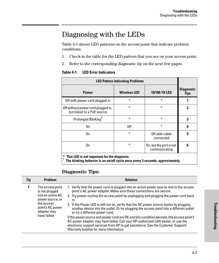
Diagnosing with the LEDs Table 4-1 shows LED patterns on the access point that indicate problem conditions.
1. Check in the table for the LED pattern that you see on your access point.
2. Refer to the corresponding diagnostic tip on the next few pages.
Table 4-1. LED Error Indicators
LED Pattern Indicating Problems
Diagnostic TipsPower Wireless LED 10/100-TX LED
Off with power cord plugged in * * 1
Off without power cord plugged in, but linked to a PoE source
* * 2
Prolonged Blinking† * * 3
On Off * 4
On * Off with cable connected
5
On * On, but the port is not communicating
6
* This LED is not important for the diagnosis.† The blinking behavior is an on/off cycle once every 3 seconds, approximately.
Diagnostic Tips:
Tip Problem Solution
The access point is not plugged into an active AC power source, or the access point’s AC power adapter may have failed.
1. Verify that the power cord is plugged into an active power source and to the access point's AC power adapter. Make sure these connections are secure.
2. Try power-cycling the access point by unplugging and plugging the power cord back in.
3. If the Power LED is still not on, verify that the AC power source works by plugging another device into the outlet. Or try plugging the access point into a different outlet or try a different power cord.
If the power source and power cord are OK and this condition persists, the access point’s AC power adapter may have failed. Call your HP-authorized LAN dealer, or use the electronic support services from HP to get assistance. See the Customer Support/ Warranty booklet for more information.
1
4-3

Troubleshooting Diagnosing with the LEDs
Trou
bles
hoot
ing
Tip Problem Solution
2 The access point 1. Verify that access point’s 10/100Base-TX port is attached to a PoE source device. is not receiving 2. Verify that the PoE source device is powered on, and that the PoE function has been power from the administratively enabled on the source port attached to the access point. PoE source. 3. Refer to Tip 6 to verify that the network cable is functioning properly.
3 The access point has experienced a software failure during self test.
1. Try resetting the access point by pressing the Reset button on the back of the access point, or by power cycling the access point.
2. If the fault indication reoccurs, attach a console to the access point (as indicated in chapter 2). Then, reset the access point. Messages should appear on the console screen identifying the error condition. You can view the console log at that point using the web browser interface. Select the Status tab, then Events Log, or view the entry file on your Syslog server if one is configured.
If necessary to resolve the problem, contact your HP-authorized LAN dealer, or use the electronic support services from HP to get assistance. See the Customer Support/ Warranty booklet for more information.
4 Wireless link has Verify that the wireless port has not been disabled through an access point configuration been change. You can use the console interface, or, if you have configured an IP address on administratively the access point, use the web browser interface to determine the state of the wireless disabled. port and re-enable the port if necessary. Also verify that the country code has been set.
5 The Try the following procedures: 10/100Base-TX • Verify that both ends of the cabling, at the access point and the connected device, are network connected properly. connection is not • Verify the connected device and access point are both powered on and operatingworking correctly. properly. • Verify duplex operation (see page 4-1).
• If these procedures don’t resolve the problem, try using a different cable.
6 The port may be VLAN configuration may affect the port operation. Use the access point’s console to see improperly how the port is configured for VLANs. configured. Make sure also, that the device at the other end of the connection is indicating a good
link to the access point. If it is not, the problem may be with the cabling between the devices or the connectors on the cable.
4-4
Troubleshooting Proactive Networking
Troubleshooting
Proactive Networking
The following interfaces provide tests, indicators, and an event log that can be used to monitor the access point and its network connections and to help you troubleshoot:
■ A graphical web browser interface that you can use to manage your access point from a PC running a supported web browser, for example Microsoft Internet Explorer. The Status tab can be used to display access point configuration settings, attached client station settings, and the event log.
■ A full-featured easy-to-use console interface that you can access by connecting a standard terminal or PC running a terminal emulator to the access point’s console port. (For information on the console port’s pin assignments, see “Direct Console Access” on page 2-12.) The console interface is also accessible through a Telnet connection. The ping command can test device access and connectivity. The show command at all levels of the CLI provides detailed access point configuration information.
4-5
Troubleshooting Hardware Diagnostic Tests
Trou
bles
hoot
ing
Hardware Diagnostic Tests
Testing the Access Point by Resetting It
If you believe that the access point is not operating correctly, you can reset the access point to test its circuitry and operating code. To reset an access point, either
■ Unplug and plug in the power cord (power-cycling).
■ Press the Reset button on the back of the access point for just a second. If you are attached to the console port, you will see that the access point starts the power-on self test.
C a u t i o n If you hold the reset button down for 5-10 seconds, you reset the board and reload the factory default settings. See “Restoring the Factory Default Configuration” on page 4-8.
Power-cycling the access point and pressing the Reset button both cause the access point to perform its power-on self test, which normally resolves any temporary operational problems. These reset processes also cause any network traffic counters to be reset to zero, and cause the System Up Time timer to reset to zero. Also, event log messages are erased, and the IP address may be changed if you are using DHCP.
Checking the Access Point’s LEDs
The self test passes if the Power LED on the front of the access point stops blinking after approximately 50 seconds. If this LED continues blinking longer than 60 seconds or goes off, there may be a problem with the access point.
See “Diagnosing with the LEDs” on page 4-3 for information on interpreting the LED patterns.
Checking Event Messages
Useful diagnostic messages may be displayed on the console screen when the access point is reset. As described in chapter 2 under step 7, “Connect a console to the access point,” connect a PC running a VT-100 terminal emulator program or a standard VT-100 terminal to the access point’s Console Port and configure it with the terminal communication settings shown on page 2-11.
4-6
Troubleshooting Hardware Diagnostic Tests
Troubleshooting
Then, when you reset the access point, note the messages that are displayed. Additionally, you can check the access point’s event log, which can be accessed from the web browser or a Syslog server.
Testing Twisted-Pair Cabling
Network cables that fail to provide a link or provide an unreliable link between the access point and the connected network device may not be compatible with the IEEE 802.3 Type 10Base-T, or 100Base-TX standards. The twisted-pair cables attached to the Access Point 420 must be compatible with the appropriate standards. To verify that your cable is compatible with these standards, use a qualified cable test device.
Testing Access Point-to-Device Network Communications
You can perform the following communication tests to verify that the network is operating correctly between the access point and any connected device that can respond correctly to the communication test.
■ Ping Test -- a network layer test used on IP networks that sends test packets to any device identified by its IP address
These tests can be performed through the access point’s console interface from a terminal connected to the access point or through a Telnet connection. For more information, see the Management and Configuration Guide, which is on the Documentation CD-ROM that came with your access point.
Testing End-to-End Network Communications
Both the access point and the cabling can be tested by running an end-to-end communications test -- a test that sends known data from one network device to another through the access point. You can run a Ping test to verify that the entire communication path between the two network devices is functioning correctly.
4-7
Troubleshooting Restoring the Factory Default Configuration
Trou
bles
hoot
ing
Restoring the Factory Default Configuration
As part of your troubleshooting process on the Access Point 420, it may become necessary to return the access point’s configuration to the factory default settings. This process momentarily interrupts the access point’s operation, clears any passwords, clears the console event log, resets the network counters to zero, performs a complete self test, and reboots the access point into its factory default configuration including deleting the IP address, if one is configured.
N o t e This process removes all access point configuration changes that you have made from the factory default settings. This includes, for example, IP addresses, and radio interface settings. Returning the configuration of these features to their factory default settings may result in network connectivity issues.
If the access point has a valid configuration, and you are restoring the factory default settings for a reason other than configuration problems, you should save the access point configuration prior to performing the factory default reset. Then, after the reset and resolution of the original problem, you can restore the saved configuration to the access point. For both the save and restore processes, you can use the console copy command. For more information on this command, see the Management and Configuration Guide, which is on the Documentation CD-ROM that came with your access point.
You can restore the factory default configuration either from the access point itself, or through the access point console.
To execute the factory default reset on the access point, perform these steps:
1. Using a pointed object, press and hold the Reset button on the back of the access point for 5-10 seconds. On the console display, the cursor will move down to the next line, indicating that the factory defaults have been reloaded.
2. Release the Reset button.
The access point will then complete its self test and begin operating with its configuration restored to the factory default settings.
To restore the factory default configuration using the console, execute the reset configuration command from the console command prompt.
4-8

Troubleshooting Downloading New Access Point Software
Troubleshooting
Downloading New Access Point Software When product enhancements occur for the Access Point 420, new software can be downloaded to the access point by several methods. For more information, see the Management and Configuration Guide, which is on the Documentation CD-ROM that came with your access point.
The new access point software is made available on the HP ProCurve web site, http://www.hp.com/go/hpprocurve under “product support – software upgrades.”
HP Customer Support Services If you are still having trouble with your access point, Hewlett-Packard offers support 24 hours a day, seven days a week through the use of a number of automated electronic services. See the Customer Support/Warranty booklet that came with your access point for information on how to use these services to get technical support. The HP ProCurve web site, http://www.hp.com/go/
hpprocurve also provides up-to-date support information under “product support.
Additionally, your HP-authorized network reseller can provide you with assistance, both with services that they offer and with services offered by HP.
Before Calling Support
To make the support process most efficient, before calling your networking dealer or HP Support, you first should retrieve the following information:
Information Item Information Location
• product identification the front of the access point, Access Point 420 (HP J8130A or HP J8131A)
• details about the access point’s status • access point console (Global Configuraincluding the software (OS) version, a tion Level): show command copy of the access point configuration, • access point web interface: Event Log a copy of the access point Event Log, • Syslog server entry file, if configured and a copy of the access point status and counters information
4-9

Troubleshooting HP Customer Support Services
Trou
bles
hoot
ing
Information Item Information Location
• copy of your network topology map, in- your network records cluding network addresses assigned to the relevant devices
4-10

Specifications
A
Specifications
Physical
Width:
Depth:
Height:
Weight:
Electrical
Adapter
AC voltage:
DC voltage:
Power consumption:
PoE (DC)
Input voltage:
21.83 cm (8.60 in)
13.73 cm (5.40 in)
3.27 cm (1.29 in)
0.80 kg (1.76 lbs)
100-240 volts, 0.4A, 50/60 Hz
3.3 volts, 4A
13.2 watts
-48 VDC, 0.27A, 12.96 watts
Note: Power can also be provided to the access point through the Ethernet port based on IEEE 802.3af Power over Ethernet (PoE) specifications. When both PoE is provided and the adapter is plugged in, PoE is turned off.
Environmental
Operating Non-Operating
Temperature: 0°C to 40°C (32°F to 104°F) -40°C to 70°C (-40°F to 158°F)
Relative humidity: 15% to 95% at 40°C (104°F) 90% maximum at 65°C (149°F) (non-condensing)
Maximum altitude: 4.6 Km (15,000 ft) 4.6 Km (15,000 ft)
A-1
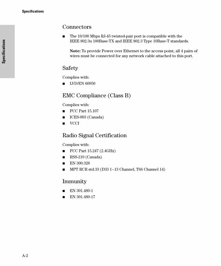
Spec
ifica
tions
Specifications
Connectors
■ The 10/100 Mbps RJ-45 twisted-pair port is compatible with the IEEE 802.3u 100Base-TX and IEEE 802.3 Type 10Base-T standards.
Note: To provide Power over Ethernet to the access point, all 4 pairs of wires must be connected for any network cable attached to this port.
Safety
Complies with:
■ LVD/EN 60950
EMC Compliance (Class B)
Complies with:
■ FCC Part 15.107
■ ICES-003 (Canada)
■ VCCI
Radio Signal Certification
Complies with:
■ FCC Part 15.247 (2.4GHz)
■ RSS-210 (Canada)
■ EN 300.328
■ MPT RCR std.33 (D33 1~13 Channel, T66 Channel 14)
Immunity
■ EN 301.489-1
■ EN 301.489-17
A-2
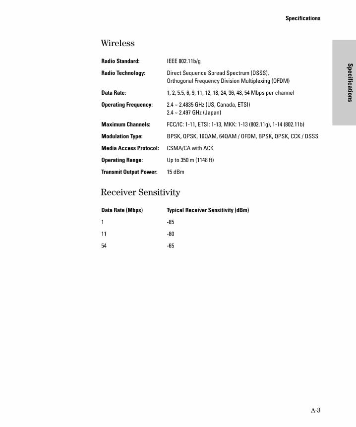
Specifications
Specifications
Wireless
Radio Standard: IEEE 802.11b/g
Radio Technology: Direct Sequence Spread Spectrum (DSSS), Orthogonal Frequency Division Multiplexing (OFDM)
Data Rate: 1, 2, 5.5, 6, 9, 11, 12, 18, 24, 36, 48, 54 Mbps per channel
Operating Frequency: 2.4 ~ 2.4835 GHz (US, Canada, ETSI) 2.4 ~ 2.497 GHz (Japan)
Maximum Channels: FCC/IC: 1-11, ETSI: 1-13, MKK: 1-13 (802.11g), 1-14 (802.11b)
Modulation Type: BPSK, QPSK, 16QAM, 64QAM / OFDM, BPSK, QPSK, CCK / DSSS
Media Access Protocol: CSMA/CA with ACK
Operating Range: Up to 350 m (1148 ft)
Transmit Output Power: 15 dBm
Receiver Sensitivity
Data Rate (Mbps) Typical Receiver Sensitivity (dBm)
1 -85
11 -80
54 -65
A-3

Specifications
Spec
ifica
tions
A-4
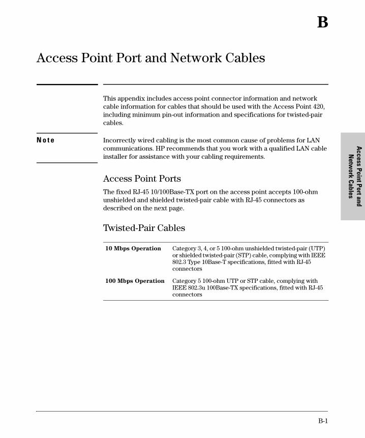
Netw
ork Cables A
ccess Point Port and
B
Access Point Port and Network Cables
This appendix includes access point connector information and network cable information for cables that should be used with the Access Point 420, including minimum pin-out information and specifications for twisted-pair cables.
N o t e Incorrectly wired cabling is the most common cause of problems for LAN communications. HP recommends that you work with a qualified LAN cable installer for assistance with your cabling requirements.
Access Point Ports The fixed RJ-45 10/100Base-TX port on the access point accepts 100-ohm unshielded and shielded twisted-pair cable with RJ-45 connectors as described on the next page.
Twisted-Pair Cables
10 Mbps Operation Category 3, 4, or 5 100-ohm unshielded twisted-pair (UTP) or shielded twisted-pair (STP) cable, complying with IEEE 802.3 Type 10Base-T specifications, fitted with RJ-45 connectors
100 Mbps Operation Category 5 100-ohm UTP or STP cable, complying with IEEE 802.3u 100Base-TX specifications, fitted with RJ-45 connectors
B-1

Access Point Port and Network Cables Twisted-Pair Cable/Connector Pin-Outs
Acce
ss P
oint
Por
t and
N
etw
ork
Cabl
es
Twisted-Pair Cable/Connector Pin-Outs
The access point includes one 10/100Base-TX port. This port uses MDI (i.e., internal straight-through) pin configuration. You can therefore use “straight-through” twisted-pair cable to connect this port to most network interconnection devices such as a switch or a router that provide MDI-X ports. However, if you need to connect the access point to a workstation or other device that only has MDI ports, then use “crossover” twisted-pair cable.
Ports on most HP switches have the “HP Auto MDIX” feature, which means
that you can use either straight-through or crossover twisted-pair cables to
connect the access point to the switch.
Other Wiring Rules:
■ All twisted-pair wires used for 10 Mbps, and 100 Mbps operation must be twisted through the entire length of the cable. The wiring sequence must conform to EIA/TIA 568-B (not USOC). See “Twisted-Pair Cable Pin Assignments” later in this appendix for a listing of the signals used on each pin.
■ For 10 Mbps connections to the ports, you can use Category 3, 4, or 5 unshielded twisted-pair cable, as supported by the IEEE 802.3 Type 10Base-T standard.
■ For 100 Mbps connections to the ports, use 100-ohm Category 5 UTP or STP cable only, as supported by the IEEE 802.3u Type 100Base-TX standard.
■ To provide Power over Ethernet to the access point, all 4 pairs must be connected for any network cable attached to this port; the cable must meet ISO/DIS 11801 Class D requirements and IEEE 802.3af requirements.
B-2
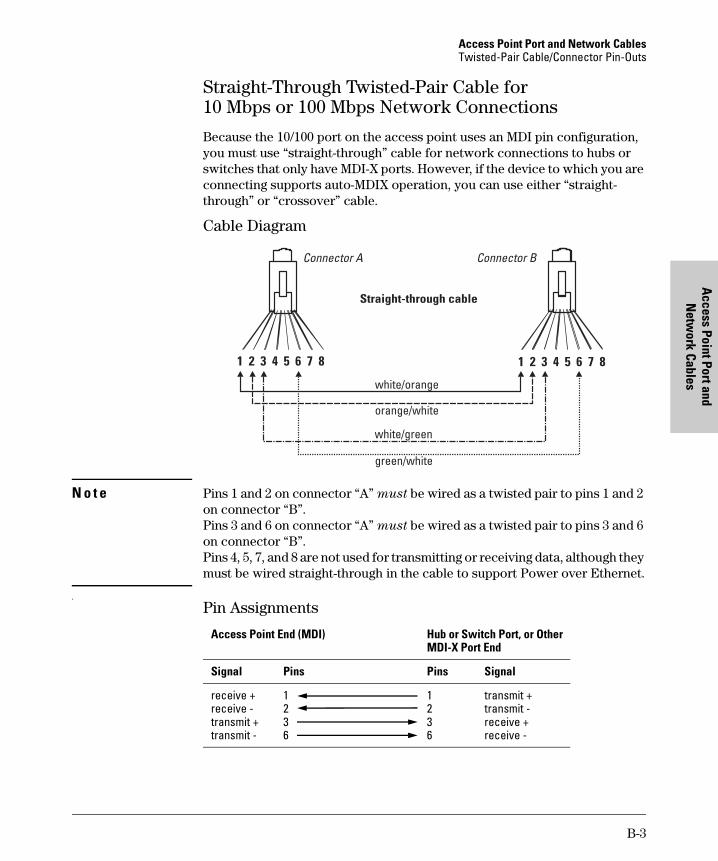
Access Point Port and Network Cables Twisted-Pair Cable/Connector Pin-Outs
Netw
ork Cables A
ccess Point Port and
Straight-Through Twisted-Pair Cable for 10 Mbps or 100 Mbps Network Connections
Because the 10/100 port on the access point uses an MDI pin configuration, you must use “straight-through” cable for network connections to hubs or switches that only have MDI-X ports. However, if the device to which you are connecting supports auto-MDIX operation, you can use either “straight-through” or “crossover” cable.
Cable Diagram
N o t e Pins 1 and 2 on connector “A” must be wired as a twisted pair to pins 1 and 2 on connector “B”. Pins 3 and 6 on connector “A” must be wired as a twisted pair to pins 3 and 6 on connector “B”. Pins 4, 5, 7, and 8 are not used for transmitting or receiving data, although they must be wired straight-through in the cable to support Power over Ethernet.
.
Pin Assignments
Access Point End (MDI) Hub or Switch Port, or Other MDI-X Port End
Signal Pins Pins Signal
receive + 1 1 transmit + receive - 2 2 transmit -transmit + 3 3 receive + transmit - 6 6 receive -
B-3
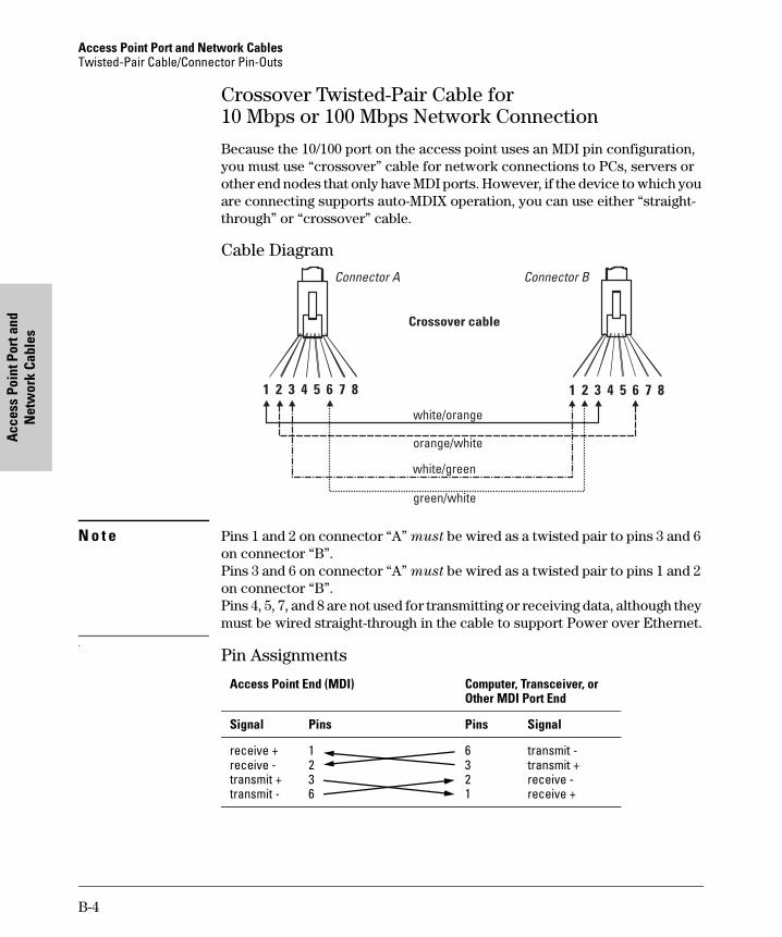
Access Point Port and Network Cables Twisted-Pair Cable/Connector Pin-Outs
Acce
ss P
oint
Por
t and
N
etw
ork
Cabl
es
Crossover Twisted-Pair Cable for 10 Mbps or 100 Mbps Network Connection
Because the 10/100 port on the access point uses an MDI pin configuration, you must use “crossover” cable for network connections to PCs, servers or other end nodes that only have MDI ports. However, if the device to which you are connecting supports auto-MDIX operation, you can use either “straight-through” or “crossover” cable.
Cable Diagram
N o t e Pins 1 and 2 on connector “A” must be wired as a twisted pair to pins 3 and 6 on connector “B”. Pins 3 and 6 on connector “A” must be wired as a twisted pair to pins 1 and 2 on connector “B”. Pins 4, 5, 7, and 8 are not used for transmitting or receiving data, although they must be wired straight-through in the cable to support Power over Ethernet.
.
Pin Assignments
Access Point End (MDI) Computer, Transceiver, or Other MDI Port End
Signal Pins Pins Signal
receive + 1 6 transmit -receive - 2 3 transmit + transmit + 3 2 receive -transmit - 6 1 receive +
B-4

Statements
Safety and EMC Regulatory
C
Safety and EMC Regulatory Statements
Safety Information
! Documentation reference symbol. If the product is marked with this symbol, refer to the product documentation to get more information about the product.
WARNING A WARNING in the manual denotes a hazard that can cause injury or death.
CAUTION A CAUTION in the manual denotes a hazard that can damage equipment.
Do not proceed beyond a WARNING or CAUTION notice until you have understood the hazardous conditions and have taken appropriate steps.
Grounding
This product is a safety class I compliant product and has a protective earthing terminal. There must be an uninterruptible safety earth ground from the main power source to the product's power cord or supplied power cord set. Whenever it is likely that the protection has been impaired, disconnect the power cord until the ground has been restored..
For LAN cable grounding:
■ If your LAN covers an area served by more than one power distribution system, be sure their safety grounds are securely interconnected.
■ LAN cables may occasionally be subject to hazardous transient volt-ages (such as lightning or disturbances in the electrical utilities power grid). Handle exposed metal components of the network with caution.
Servicing
There are no user-serviceable parts inside this product. Any servicing, adjustment, maintenance, or repair must be performed only by service-trained personnel.
This product does not have a power switch; it is powered on when the power cord is plugged in.
C-1

Safety and EMC Regulatory Statements Safety Information
Safe
ty a
nd E
MC
Regu
lato
ry
Stat
emen
ts
Regulatory Model Identification Number
For regulatory identification purposes, this product has been assigned a Regulatory Model Number (RMN). The RMN for your product is RSVLC-0301. The RMN should not be confused with the marketing name (Wireless Enterprise Access Point 420) or the Product Number (J8130A, J8131A).
C-2

Safety and EMC Regulatory Statements Informations concernant la sécurité
Statements
Safety and EMC Regulatory
Informations concernant la sécurité
! Symbole de référence à la documentation. Si le produit est marqué de ce symbole, reportez-vous à la documentation du produit afin d'obtenir des informations plus détaillées.
WARNING Dans la documentation, un WARNING indique un danger susceptible d'entraîner des dommages corporels ou la mort.
CAUTION Un texte de mise en garde intitulé CAUTION indique un danger susceptible de causer des dommages à l'équipement.
Ne continuez pas au-delà d'une rubrique WARNING ou CAUTION avant d'avoir bien compris les conditions présentant un danger et pris les mesures appropriées.
Cet appareil est un produit de classe I et possède une borne de mise à la terre. La source d'alimentation principale doit être munie d'une prise de terre de sécurité installée aux bornes du câblage d'entrée, sur le cordon d'alimentation ou le cordon de raccordement fourni avec le produit. Lorsque cette protection semble avoir été endommagée, débrancher le cordon d'alimentation jusqu'à ce que la mise à la terre ait été réparée.
Mise à la terre du câble de réseau local:
■ si votre réseau local s'étend sur une zone desservie par plus d'un système de distribution de puissance, assurez-vous que les prises de terre de sécurité soient convenablement interconnectées.
■ Les câbles de réseaux locaux peuvent occasionnellement être soumis à des surtensions transitoires dangereuses (telles que la foudre ou des perturbations dans le réseau d'alimentation public). Manipulez les composants métalliques du réseau avec précautions.
Aucune pièce contenue à l'intérieur de ce produit ne peut être réparée par l'utilisateur. Tout dépannage, réglage, entretien ou réparation devra être confié exclusivement à un personnel qualifié.
Cet appareil ne comporte pas de commutateur principal ; la mise sous tension est effectuée par branchement du cordon d'alimentation.
C-3
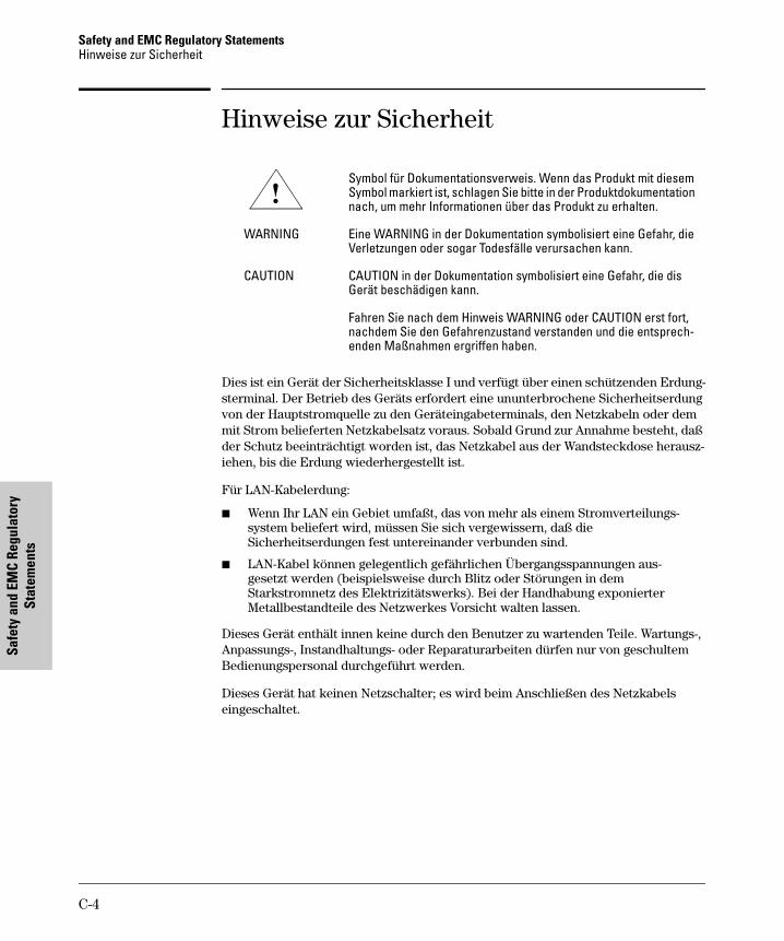
Safety and EMC Regulatory Statements Hinweise zur Sicherheit
Safe
ty a
nd E
MC
Regu
lato
ry
Stat
emen
ts
Hinweise zur Sicherheit
! Symbol für Dokumentationsverweis. Wenn das Produkt mit diesem Symbol markiert ist, schlagen Sie bitte in der Produktdokumentation nach, um mehr Informationen über das Produkt zu erhalten.
WARNING Eine WARNING in der Dokumentation symbolisiert eine Gefahr, die Verletzungen oder sogar Todesfälle verursachen kann.
CAUTION CAUTION in der Dokumentation symbolisiert eine Gefahr, die dis Gerät beschädigen kann.
Fahren Sie nach dem Hinweis WARNING oder CAUTION erst fort, nachdem Sie den Gefahrenzustand verstanden und die entsprechenden Maßnahmen ergriffen haben.
Dies ist ein Gerät der Sicherheitsklasse I und verfügt über einen schützenden Erdungsterminal. Der Betrieb des Geräts erfordert eine ununterbrochene Sicherheitserdung von der Hauptstromquelle zu den Geräteingabeterminals, den Netzkabeln oder dem mit Strom belieferten Netzkabelsatz voraus. Sobald Grund zur Annahme besteht, daß der Schutz beeinträchtigt worden ist, das Netzkabel aus der Wandsteckdose herausziehen, bis die Erdung wiederhergestellt ist.
Für LAN-Kabelerdung:
■ Wenn Ihr LAN ein Gebiet umfaßt, das von mehr als einem Stromverteilungssystem beliefert wird, müssen Sie sich vergewissern, daß die Sicherheitserdungen fest untereinander verbunden sind.
■ LAN-Kabel können gelegentlich gefährlichen Übergangsspannungen ausgesetzt werden (beispielsweise durch Blitz oder Störungen in dem Starkstromnetz des Elektrizitätswerks). Bei der Handhabung exponierter Metallbestandteile des Netzwerkes Vorsicht walten lassen.
Dieses Gerät enthält innen keine durch den Benutzer zu wartenden Teile. Wartungs-, Anpassungs-, Instandhaltungs- oder Reparaturarbeiten dürfen nur von geschultem Bedienungspersonal durchgeführt werden.
Dieses Gerät hat keinen Netzschalter; es wird beim Anschließen des Netzkabels eingeschaltet.
C-4
Safety and EMC Regulatory Statements Considerazioni sulla sicurezza
Statements
Safety and EMC Regulatory
Considerazioni sulla sicurezza
! Simbolo di riferimento alla documentazione. Se il prodotto è contrassegnato da questo simbolo, fare riferimento alla documentazione sul prodotto per ulteriori informazioni su di esso.
WARNING La dicitura WARNINGdenota un pericolo che può causare lesioni o morte.
CAUTION La dicituraCAUTION denota un pericolo che può danneggiare le attrezzature.
Non procedere oltre un avviso di WARNING o di CAUTIONprima di aver compreso le condizioni di rischio e aver provveduto alle misure del caso.
Questo prodotto è omologato nella classe di sicurezza I ed ha un terminale protettivo di collegamento a terra. Dev'essere installato un collegamento a terra di sicurezza, non interrompibile che vada dalla fonte d'alimentazione principale ai terminali d'entrata, al cavo d'alimentazione oppure al set cavo d'alimentazione fornito con il prodotto. Ogniqualvolta vi sia probabilità di danneggiamento della protezione, disinserite il cavo d'alimentazione fino a quando il collegaento a terra non sia stato ripristinato.
Per la messa a terra dei cavi LAN:
■ se la vostra LAN copre un'area servita da più di un sistema di distribuzione elettrica, accertatevi che i collegamenti a terra di sicurezza siano ben collegati fra loro;
■ i cavi LAN possono occasionalmente andare soggetti a pericolose tensioni transitorie (ad esempio, provocate da lampi o disturbi nella griglia d'alimentazione della società elettrica); siate cauti nel toccare parti esposte in metallo della rete.
Nessun componente di questo prodotto può essere riparato dall'utente. Qualsiasi lavoro di riparazione, messa a punto, manutenzione o assistenza va effettuato esclusivamente da personale specializzato.
Questo apparato non possiede un commutatore principale; si mette scotto tensione all'inserirsi il cavo d'alimentazione.
C-5

Safety and EMC Regulatory Statements Consideraciones sobre seguridad
Safe
ty a
nd E
MC
Regu
lato
ry
Stat
emen
ts
Consideraciones sobre seguridad
! Símbolo de referencia a la documentación. Si el producto va marcado con este símbolo, consultar la documentación del producto a fin de obtener mayor información sobre el producto.
WARNING Una WARNING en la documentación señala un riesgo que podría resultar en lesiones o la muerte.
CAUTION Una CAUTION en la documentación señala un riesgo que podría resultar en averías al equipo.
No proseguir después de un símbolo de WARNING o CAUTION hasta no haber entendido las condiciones peligrosas y haber tomado las medidas apropiadas.
Este aparato se enmarca dentro de la clase I de seguridad y se encuentra protegido por una borna de puesta a tierra. Es preciso que exista una puesta a tierra continua desde la toma de alimentación eléctrica hasta las bornas de los cables de entrada del aparato, el cable de alimentación o el juego de cable de alimentación suministrado. Si existe la probabilidad de que la protección a tierra haya sufrido desperfectos, desenchufar el cable de alimentación hasta haberse subsanado el problema.
Puesta a tierra del cable de la red local (LAN):
■ Si la LAN abarca un área cuyo suministro eléctrico proviene de más de una red de distribución de electricidad, cerciorarse de que las puestas a tierra estén conectadas entre sí de modo seguro.
■ Es posible que los cables de la LAN se vean sometidos de vez en cuando a voltajes momentáneos que entrañen peligro (rayos o alteraciones en la red de energía eléctrica). Manejar con precaución los componentes de metal de la LAN que estén al descubierto.
Este aparato no contiene pieza alguna susceptible de reparación por parte del usuario. Todas las reparaciones, ajustes o servicio de mantenimiento debe realizarlos solamente el técnico.
Este producto no tiene interruptor de potencia; se activa cuando se enchufa el cable de alimentación.
C-6

Safety and EMC Regulatory Statements Safety Information (Japan)
Statements
Safety and EMC Regulatory
Safety Information (Japan)
C-7

Safety and EMC Regulatory Statements Safety Information (China)
Safe
ty a
nd E
MC
Regu
lato
ry
Stat
emen
ts
Safety Information (China)
C-8

Safety and EMC Regulatory Statements EMC Regulatory Statements
Statements
Safety and EMC Regulatory
EMC Regulatory Statements
Notice for U.S.A.
Manufacturer's FCC Declaration of Conformity Statement
Tested to Comply with FCC Standards
Product No: J8130A
FCC ID No: HEDWA4101ACCAA
Manufacturer: Hewlett-Packard Company 3000 Hanover Street Palo Alto, CA 94304-1185 USA
Phone: 650-857-1501
For questions regarding this declaration, contact the Product Regulations Manager at the above address or phone number.
This device complies with Part 15 of the FCC rules. Operation is subject to the following two conditions: 1) this device may not cause harmful interference, and 2) this device must accept any interference received, including interference that may cause undesired operation.
This equipment has been tested and found to comply with the limits for a Class B digital device, pursuant to Part 15 of the FCC Rules. These limits are designed to provide reasonable protection against harmful interference in a residential installation. This equipment generates, uses and can radiate radio frequency energy and, if not installed and used in accordance with instructions, may cause harmful interference to radio communications. However, there is no guarantee that the interference will not occur in a particular installation. If this equipment does cause harmful interference to radio or television reception, which can be determined by turning the equipment off and on, the user is encouraged to try to correct the interference by one or more of the following measures:
■ Reorient the receiving antenna ■ Increase the separation between the equipment and receiver ■ Connect the equipment into an outlet on a circuit different from that to
which the receiver is connected ■ Consult the dealer or an experienced radio/TV technician for help
C-9

Safety and EMC Regulatory Statements EMC Regulatory Statements
Safe
ty a
nd E
MC
Regu
lato
ry
Stat
emen
ts
The FCC requires the user to be notified that any changes or modifications made to the device that are not expressly approved by the Hewlett-Packard Company may void the user's authority to operate the equipment.
! Warning: Exposure to Radio Frequency Radiation
The radiated output power of this device is below the FCC radio exposure limits. Nevertheless, the device should be used in such a manner that the potential for human contact during normal operation is minimized. To avoid the possibility of exceeding the FCC radio frequency exposure limits, human proximity to the antennas should not be less than 20 cm (8 inches) during normal operation.
Notice for Canada
This device complies with the limits for a Class B digital device and conforms to Industry Canada standard ICES-003. Products that contain a radio transmitter comply with Industry Canada standard RSS210 and are labeled with an IC approval number.
Cet appareil numérique de la classe B est conforme à la norme ICES-003 de Industry Canada. La radio sans fil de ce dispsitif est conforme à la certification RSS 210 de Industry Canada et est étiquetée avec un numéro d'approbation IC.
This device complies with the Class B limits of Industry Canada. Operation is subject to the following two conditions: 1) this device may not cause harmful interference, and 2) this device must accept interference received, including interference that may cause undesired operation.
C-10

Safety and EMC Regulatory Statements EMC Regulatory Statements
Statements
Safety and EMC Regulatory
Notice for European Community
0560 !
This device complies with the EMC Directive 89/336/EEC, Low Voltage Directive 73/23/EEC and R&TTE Directive 1999/5/EC. Compliance with these directives implies conformity to the following European Norms:
• EN 55022 (CISPR 22) - Electromagnetic Emissions
• EN 55024 (IEC 61000-4-2, 3, 4, 5, 6, 8, 11) - Electromagnetic Immunity
• EN 61000-3-2 (IEC 61000-3-2) - Power Line Harmonics
• EN 61000-3-3 (IEC 61000-3-3) - Power Line Flicker
• EN 60950 (IEC 60950) - Product Safety
• EN 300 328-1 / EN 300 328-2 - Technical requirements for 2.4 GHz radio equipment
• EN 301 489-1 / EN 301 489-17 - General EMC requirements for radio equipment
EU country restriction notices
This device may be used in the following EU and EFTA countries:
• Austria • Germany • Liechtenstein • Sweden
• Belgium • Greece • Luxembourg • Switzerland
• Denmark • Iceland • Netherlands • United Kingdom
• Finland • Ireland • Norway
• France1 • Italy • Portugal
Notes:
1. For normal wireless LAN operation of this device, only a limited band is available for operation in France (Channels 10, 11, 12, and 13). L'Autorité de régulation des telecommunications (ART) has special regulations for hotspots allowing other channels, too. Please check with ART (http:// www.art-telecom.fr) for local rulings and authorization.
2. For up-to-date information on worldwide country authorizations, power levels and usage restrictions, please visit http://www.hp.com/go/ hpprocurve. Click on technical support, then manuals. Select your wire-less product and open the document Wireless Radio Country Approvals
Matrix.
C-11
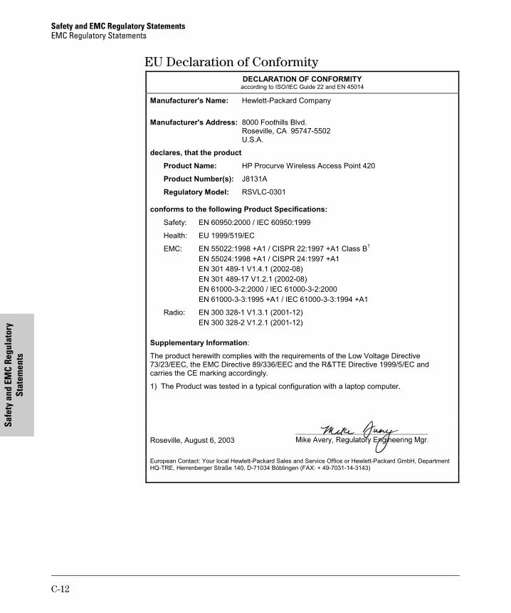
Safety and EMC Regulatory Statements EMC Regulatory Statements
Safe
ty a
nd E
MC
Regu
lato
ry
Stat
emen
ts
EU Declaration of Conformity DECLARATION OF CONFORMITY
according to ISO/IEC Guide 22 and EN 45014
Manufacturer's Name: Hewlett-Packard Company
Manufacturer's Address: 8000 Foothills Blvd. Roseville, CA 95747-5502 U.S.A.
declares, that the product
Product Name: HP Procurve Wireless Access Point 420
Product Number(s): J8131A
Regulatory Model: RSVLC-0301
conforms to the following Product Specifications:
Safety: EN 60950:2000 / IEC 60950:1999
Health: EU 1999/519/EC
EMC: EN 55022:1998 +A1 / CISPR 22:1997 +A1 Class B1
EN 55024:1998 +A1 / CISPR 24:1997 +A1
EN 301 489-1 V1.4.1 (2002-08)
EN 301 489-17 V1.2.1 (2002-08)
EN 61000-3-2:2000 / IEC 61000-3-2:2000
EN 61000-3-3:1995 +A1 / IEC 61000-3-3:1994 +A1
Radio: EN 300 328-1 V1.3.1 (2001-12)
EN 300 328-2 V1.2.1 (2001-12)
Supplementary Information:
The product herewith complies with the requirements of the Low Voltage Directive 73/23/EEC, the EMC Directive 89/336/EEC and the R&TTE Directive 1999/5/EC and carries the CE marking accordingly.
1) The Product was tested in a typical configuration with a laptop computer.
Roseville, August 6, 2003
European Contact: Your local Hewlett-Packard Sales and Service Office or Hewlett-Packard GmbH, Department HQ-TRE, Herrenberger Straße 140, D-71034 Böblingen (FAX: + 49-7031-14-3143)
C-12

Safety and EMC Regulatory Statements EMC Regulatory Statements
Statements
Safety and EMC Regulatory
Notice for Japan
C-13

Safety and EMC Regulatory Statements EMC Regulatory Statements
Safe
ty a
nd E
MC
Regu
lato
ry
Stat
emen
ts
C-14

Index
Index
Numerics
10/100Base-TX connections, length limitations … 2-4 ports, cables used with … 2-4
10/100Base-TX port location on access point … 1-5
10/100-T LED … 1-4 behaviors … 1-4
A
access point connecting to a power source … 2-9 description … 1-1 downloading new software … 4-9 electrical specifications … A-1 emmissions specifications … A-2 environmental specifications … A-1 features … 1-8 included parts … 2-1 LED descriptions … 1-4 mounting on a wall … 2-7 mounting on horizontal surface … 2-9 physical specifications … A-1 top panel description … 1-3
access point operation verifying after installation … 2-5
antennas location on access point … 1-5
auto MDI/MDI-X operation … B-3
B
back of access point 10/100Base-TX port … 1-5 console port … 1-6 description … 1-5 lock … 1-5 network port … 1-6 power connector … 1-6
basic access point configuration command line interface … 3-2
basic troubleshooting tips … 4-1
blinking LEDs error indications … 4-3
buttons Reset button … 1-7
C
cables 10/100Base-TX connections … 2-4 connecting cables to the access point
port … 2-10 effects of non-standard cables … 4-2 infrastructure requirements … 2-4 length limitations … 2-4 required types … 2-4 serial, for direct console connection … 2-12
cables, twisted pair access point-to-computer connection … B-3 access point-to-switch or hub connection … B-4 category 3, 4, 5 … B-2 cross-over cable pin-out … B-4 MDI-X to MDI connections … B-3 MDI-X to MDI-X connections … B-4 pin-outs … B-3 straight-through cable pin-out … B-3
cables, twisted-pair wiring rules … B-2
cables, twisted-pair connector pin-outs … B-2 cabling infrastructure … 2-4 CLI prompt, console
displaying … 2-13 command line interface
key command descriptions … 3-6 configuration
command line interface … 3-2 DHCP … 3-2 IP address, manually … 3-2 restoring factory defaults … 4-8
connecting the access point to a power source … 2-9 connector specifications … A-2
Index – 1

Inde
x
console checking messages during
troubleshooting … 4-6command line interface … 3-2displaying the CLI prompt … 2-13features … 2-11how to connect in-band … 2-11how to connect out-of-band … 2-11serial cable connection … 2-12Telnet access … 3-8terminal configuration … 2-11
console portlocation on access point … 1-5–1-6
cross-over cablepin-out … B-4
D
DC power connectorlocation on back of access point … 1-5
descriptionaccess point … 1-1back of access point … 1-5LEDs … 1-4top of access point … 1-3
DHCPautomatic access point configuration … 3-2for in-band access … 2-11
diagnostic tests … 4-6checking the console messages … 4-6checking the LEDs … 4-6end-to-end connectivity … 4-7testing the access point only … 4-6testing twisted-pair cabling … 4-7
downloading new access point software … 4-9
E
electrical specifications, access point … A-1EMC regulatory statements … C-9emmissions specifications, access point … A-2environmental specifications, access point … A-1
F
factory default configuration, restoring … 4-8
featuresaccess point … 1-8console … 2-11
front of access pointReset button … 1-7
full-duplex fixed configurationeffects on network connections … 4-1
H
horizontal surfacemounting access point on … 2-9
I
in-band … 3-1in-band console access
types of … 2-11included parts … 2-1installation
connecting the access point to a power source … 2-9
horizontal surface mounting … 2-9location considerations … 2-4network cable requirements … 2-4precautions … 2-3site preparation … 2-4summary of steps … 2-2wall mounting … 2-7
L
LEDs10/100-T … 1-4behavior during self test … 2-6blinking definition … 1-4checking during troubleshooting … 4-6descriptions of … 1-4error indications … 4-3location on access point … 1-3on access point … 1-4Power … 1-4
behavior during self test … 2-6Self Test
behavior during self test … 2-6Wireless … 1-4
length limitations10/100Base-TX connections … 2-4
2 – Index

Index
location for the access point, considerations … 2-4lock
location on access point … 1-5
M
MDI-X to MDI network cable … B-3MDI-X to MDI-X network cable … B-4mounting the access point
on a horizontal surface … 2-9on a wall … 2-7
precautions … 2-7
N
network cables10/100Base-TX connections … 2-4required types … 2-4twisted-pair connector pin-outs … B-2twisted-pair, wiring rules … B-2
network devicesconnecting to the access point … 2-10
network portsconnecting to … 2-10location on access point … 1-6standards compliance … A-2types of … 2-4
non-standard network cables, effects … 4-2
O
out-of-band console access … 3-8
P
parts, included with the access point … 2-1passwords
deleting with the Reset button … 3-7if you lose the password … 3-7
physical specifications, access point … A-1Ping test … 4-7pin-outs
twisted-pair cables … B-2PoE power connector
location on back of access point … 1-5port LEDs
normal operation … 2-6
ports10/100Base-TX, location on access point … 1-5connecting to … 2-10console … 2-11network connections … 2-10
power connector … 1-6Power LED … 1-4
behavior during factory default reset … 4-8behavior during self test … 2-6behaviors … 1-4location on access point … 1-3
power sourceconnecting the access point to … 2-9
precautionsmounting the access point … 2-3power requirements … 2-3
preparing the installation site … 2-4Proactive Network tools
diagnostics with … 4-5
R
regulatory statements … C-9Reset button
description … 1-7location on access point … 1-7to delete password protection … 3-7
resetting the access pointfactory default reset … 4-8location of Reset button … 1-7troubleshooting procedure … 4-6
S
safety and regulatory statements … C-1safety specifications … A-2self test
LED behavior during … 2-6Power LED behavior … 2-6
Self Test LEDbehavior during self test … 2-6
serial cablefor direct console connection … 2-12
sides of access pointantennas … 1-5
Index – 3

Inde
x
specificationsconnectors … A-2electrical … A-1emmissions … A-2environmental … A-1physical … A-1safety … A-2wireless … A-3
straight-through cablepin-out … B-3
summaryof access point installation … 2-2of cables used with the access point … 2-4
T
Telnet access to the console … 3-8terminal configuration … 2-11testing
access point operation … 4-6access point-to-device communications … 4-7checking the console messages … 4-6checking the LEDs … 4-6diagnostic tests … 4-6end-to-end communications … 4-7Ping test … 4-7twisted-pair cabling … 4-7
tips for troubleshooting … 4-1top of access point … 1-3
description … 1-3LEDs … 1-4
topologieseffects of improper topology … 4-2samples of … 2-14
troubleshooting … 4-1basic tips … 4-1checking the console messages … 4-6checking the LEDs … 4-6common network problems … 4-1connecting to fixed full-duplex devices … 4-1diagnostic tests … 4-6effects of improper topology … 4-2effects of non-standard cables … 4-2Ping test … 4-7Proactive Network tools … 4-5restoring factory default configuration … 4-8testing connections to other devices … 4-7testing end-to-end communications … 4-7testing the access point … 4-6testing the twisted-pair cables … 4-7
twisted-pair cableaccess point-to-computer connection … B-3access point-to-switch or hub connection … B-4cross-over cable pin-out … B-4pin-outs … B-2–B-3straight-through cable pin-out … B-3testing … 4-7
V
VCCI compliance … C-13VT-100 terminal
serial cable connection for … 2-12
W
wall mounting access point on … 2-7
warranty … 1-iiwireless infrastructure
topology with … 2-15wireless infrastructure for roaming clients
topology with … 2-16Wireless LED … 1-4
behaviors … 1-4wireless specifications … A-3wiring rules for twisted-pair cables … B-2
4 – Index