Embed Size (px)
Citation preview
HP ProCurve Wireless Access Point 420
Management and Configuration Guide
September 2003
© Copyright 2003 Hewlett-Packard Development Company, L.P. The information contained herein is subject to change without notice.
This document contains proprietary information, which is protected by copyright. No part of this document may be photocopied, reproduced, or translated into another language without the prior written consent of Hewlett-Packard.
Publication Number
5990-6006 September 2003 Edition 1
Applicable Products
HP ProCurve Wireless Access Point 420 na (J8130A) HP ProCurve Wireless Access Point 420 ww (J8131A)
Trademark Credits
Windows NT®, Windows®, and MS Windows® are US registered trademarks of Microsoft Corporation.
Disclaimer
HEWLETT-PACKARD COMPANY MAKES NO WARRANTY OF ANY KIND WITH REGARD TO THIS MATERIAL, INCLUDING, BUT NOT LIMITED TO, THE IMPLIED WARRANTIES OF MERCHANTABILITY AND FITNESS FOR A PARTICULAR PURPOSE. Hewlett-Packard shall not be liable for errors contained herein or for incidental or consequential damages in connection with the furnishing, performance, or use of this material.
The only warranties for HP products and services are set forth in the express warranty statements accompanying such products and services. Nothing herein should be construed as constituting an additional warranty. HP shall not be liable for technical or editorial errors or omissions contained herein.
Hewlett-Packard assumes no responsibility for the use or reliability of its software on equipment that is not furnished by Hewlett-Packard.
Warranty
See the Customer Support/Warranty booklet included with the product.
A copy of the specific warranty terms applicable to your Hewlett-Packard products and replacement parts can be obtained from your HP Sales and Service Office or authorized dealer.
Contents
1 Getting Started
Contents . . . . . . . . . . . . . . . . . . . . . . . . . . . . . . . . . . . . . . . . . . . . . . . . . . . . . . 1-1
Introduction . . . . . . . . . . . . . . . . . . . . . . . . . . . . . . . . . . . . . . . . . . . . . . . . . . 1-2
Conventions . . . . . . . . . . . . . . . . . . . . . . . . . . . . . . . . . . . . . . . . . . . . . . . . . . 1-2
Command Syntax Statements . . . . . . . . . . . . . . . . . . . . . . . . . . . . . . . . . 1-2
Command Prompts . . . . . . . . . . . . . . . . . . . . . . . . . . . . . . . . . . . . . . . . . . 1-3
Screen Simulations . . . . . . . . . . . . . . . . . . . . . . . . . . . . . . . . . . . . . . . . . . 1-3
Related Publications . . . . . . . . . . . . . . . . . . . . . . . . . . . . . . . . . . . . . . . . . . 1-4
Getting Documentation From the Web . . . . . . . . . . . . . . . . . . . . . . . . . . 1-5
Sources for More Information . . . . . . . . . . . . . . . . . . . . . . . . . . . . . . . . . 1-6
Need Only a Quick Start? . . . . . . . . . . . . . . . . . . . . . . . . . . . . . . . . . . . . . . 1-6
To Set Up and Install the Access Point in Your Network . . . . . . . . . . 1-6
2 Selecting a Management Interface
Contents . . . . . . . . . . . . . . . . . . . . . . . . . . . . . . . . . . . . . . . . . . . . . . . . . . . . . . 2-1
Overview . . . . . . . . . . . . . . . . . . . . . . . . . . . . . . . . . . . . . . . . . . . . . . . . . . . . . 2-2
Understanding Management Interfaces . . . . . . . . . . . . . . . . . . . . . . . . . 2-2
Advantages of Using the CLI . . . . . . . . . . . . . . . . . . . . . . . . . . . . . . . . . . . 2-3
Advantages of Using the HP Web Browser Interface . . . . . . . . . . . . . 2-4
3 Using the Command Line Interface (CLI)
Contents . . . . . . . . . . . . . . . . . . . . . . . . . . . . . . . . . . . . . . . . . . . . . . . . . . . . . . 3-1
Overview . . . . . . . . . . . . . . . . . . . . . . . . . . . . . . . . . . . . . . . . . . . . . . . . . . . . . 3-2
Accessing the CLI . . . . . . . . . . . . . . . . . . . . . . . . . . . . . . . . . . . . . . . . . . . . . 3-2
Using the CLI . . . . . . . . . . . . . . . . . . . . . . . . . . . . . . . . . . . . . . . . . . . . . . . . . 3-2
Privilege Level at Logon . . . . . . . . . . . . . . . . . . . . . . . . . . . . . . . . . . . . . . 3-2
Privilege Level Operation . . . . . . . . . . . . . . . . . . . . . . . . . . . . . . . . . . . . . 3-4Exec Privileges . . . . . . . . . . . . . . . . . . . . . . . . . . . . . . . . . . . . . . . . . . 3-4
iii
How To Move Between Levels . . . . . . . . . . . . . . . . . . . . . . . . . . . . . . . . 3-6
Listing Commands and Command Options . . . . . . . . . . . . . . . . . . . . . . 3-7Listing Commands Available at Any Privilege Level . . . . . . . . . . . 3-7Command Option Displays . . . . . . . . . . . . . . . . . . . . . . . . . . . . . . . . 3-9
Configuration Commands and the Context Configuration Modes . . 3-10
CLI Control and Editing . . . . . . . . . . . . . . . . . . . . . . . . . . . . . . . . . . . . . . 3-12
4 Using the HP Web Browser Interface
Contents . . . . . . . . . . . . . . . . . . . . . . . . . . . . . . . . . . . . . . . . . . . . . . . . . . . . . . 4-1
Overview . . . . . . . . . . . . . . . . . . . . . . . . . . . . . . . . . . . . . . . . . . . . . . . . . . . . . 4-2
General Features . . . . . . . . . . . . . . . . . . . . . . . . . . . . . . . . . . . . . . . . . . . . . . 4-3
Starting a Web Browser Interface Session with the Access Point . 4-4
Description of Browser Interface . . . . . . . . . . . . . . . . . . . . . . . . . . . . . . 4-5
The Home Page . . . . . . . . . . . . . . . . . . . . . . . . . . . . . . . . . . . . . . . . . . . . . 4-5
Support URL . . . . . . . . . . . . . . . . . . . . . . . . . . . . . . . . . . . . . . . . . . . . . . . 4-6
Tasks for Your First HP Web Browser Interface Session . . . . . . . . . 4-7
Changing the User Name and Password in the Browser Interface . . . 4-7If You Lose the User Name or Password . . . . . . . . . . . . . . . . . . . . 4-9
Setting the SSID . . . . . . . . . . . . . . . . . . . . . . . . . . . . . . . . . . . . . . . . . . . . . 4-9
Setting the Radio Channel . . . . . . . . . . . . . . . . . . . . . . . . . . . . . . . . . . . 4-10
Configuring TCP/IP Settings . . . . . . . . . . . . . . . . . . . . . . . . . . . . . . . . . 4-12
Configuring Security Settings . . . . . . . . . . . . . . . . . . . . . . . . . . . . . . . . 4-13
Online Help for the HP Web Browser Interface . . . . . . . . . . . . . . . . . 4-16
Status Reporting Features . . . . . . . . . . . . . . . . . . . . . . . . . . . . . . . . . . . . 4-17
The AP Status Window . . . . . . . . . . . . . . . . . . . . . . . . . . . . . . . . . . . . . . 4-17
Station Status . . . . . . . . . . . . . . . . . . . . . . . . . . . . . . . . . . . . . . . . . . . . . . 4-19
Event Logs . . . . . . . . . . . . . . . . . . . . . . . . . . . . . . . . . . . . . . . . . . . . . . . . 4-20
The Status Bar . . . . . . . . . . . . . . . . . . . . . . . . . . . . . . . . . . . . . . . . . . . . . 4-21
5 Access Point Configuration
Contents . . . . . . . . . . . . . . . . . . . . . . . . . . . . . . . . . . . . . . . . . . . . . . . . . . . . . . 5-1
Overview . . . . . . . . . . . . . . . . . . . . . . . . . . . . . . . . . . . . . . . . . . . . . . . . . . . . . 5-2
iv
Modifying System Management Access . . . . . . . . . . . . . . . . . . . . . . . . . 5-3
Web: Setting User Names and Passwords . . . . . . . . . . . . . . . . . . . . . . . 5-3
CLI: Setting User Names and Passwords . . . . . . . . . . . . . . . . . . . . . . . . 5-4
Modifying System Information . . . . . . . . . . . . . . . . . . . . . . . . . . . . . . . . . 5-5
Web: Setting the System Name and SSID . . . . . . . . . . . . . . . . . . . . . . . . 5-5
CLI: Setting the System Name and SSID . . . . . . . . . . . . . . . . . . . . . . . . 5-6
Configuring IP Settings . . . . . . . . . . . . . . . . . . . . . . . . . . . . . . . . . . . . . . . . 5-9
Web: Configuring IP Settings Statically or via DHCP . . . . . . . . . . . . . . 5-9
CLI: Configuring IP Settings Statically or via DHCP . . . . . . . . . . . . . . 5-11
Configuring SNMP . . . . . . . . . . . . . . . . . . . . . . . . . . . . . . . . . . . . . . . . . . . 5-13
Web: Setting SNMP Parameters . . . . . . . . . . . . . . . . . . . . . . . . . . . . . . 5-13
CLI: Setting SNMP Parameters . . . . . . . . . . . . . . . . . . . . . . . . . . . . . . . 5-15
Enabling System Logging . . . . . . . . . . . . . . . . . . . . . . . . . . . . . . . . . . . . . 5-17
Web: Setting Logging Parameters . . . . . . . . . . . . . . . . . . . . . . . . . . . . . 5-18
CLI: Setting Logging Parameters . . . . . . . . . . . . . . . . . . . . . . . . . . . . . . 5-19
Configuring SNTP . . . . . . . . . . . . . . . . . . . . . . . . . . . . . . . . . . . . . . . . . . . . 5-21
Web: Setting SNTP Parameters . . . . . . . . . . . . . . . . . . . . . . . . . . . . . . . 5-21
CLI: Setting SNTP Parameters . . . . . . . . . . . . . . . . . . . . . . . . . . . . . . . . 5-23
Configuring Ethernet Interface Parameters . . . . . . . . . . . . . . . . . . . 5-25
Web: Setting Ethernet Interface Parameters . . . . . . . . . . . . . . . . . . . . 5-25
CLI: Setting Ethernet Interface Parameters . . . . . . . . . . . . . . . . . . . . . 5-26
Configuring RADIUS Client Authentication . . . . . . . . . . . . . . . . . . . . 5-28
Web: Setting RADIUS Server Parameters . . . . . . . . . . . . . . . . . . . . . . 5-28
CLI: Setting RADIUS Server Parameters . . . . . . . . . . . . . . . . . . . . . . . 5-30
Setting up Filter Control . . . . . . . . . . . . . . . . . . . . . . . . . . . . . . . . . . . . . 5-32
Web: Enabling VLAN Support and Setting Filters . . . . . . . . . . . . . . . . 5-33
CLI: Enabling VLAN Support and Setting Filters . . . . . . . . . . . . . . . . 5-35
Modifying Radio Settings . . . . . . . . . . . . . . . . . . . . . . . . . . . . . . . . . . . . . 5-37
Web: Modifying the Radio Working Mode and Settings . . . . . . . . . . . 5-37
CLI: Modifying the Radio Working Mode and Settings . . . . . . . . . . . . 5-40
Configuring Wireless Security . . . . . . . . . . . . . . . . . . . . . . . . . . . . . . . . 5-45
Web: Configuring WPA Settings . . . . . . . . . . . . . . . . . . . . . . . . . . . . . . 5-48
CLI: Configuring WPA Settings . . . . . . . . . . . . . . . . . . . . . . . . . . . . . . . 5-51
v
Web: Configuring MAC Address Authentication . . . . . . . . . . . . . . . . . 5-53
CLI: Configuring MAC Address Authentication . . . . . . . . . . . . . . . . . 5-55
Web: Configuring IEEE 802.1x . . . . . . . . . . . . . . . . . . . . . . . . . . . . . . . 5-57
CLI: Configuring IEEE 802.1x . . . . . . . . . . . . . . . . . . . . . . . . . . . . . . . . 5-59
Web: Setting up WEP Shared-Keys . . . . . . . . . . . . . . . . . . . . . . . . . . . . 5-61
CLI: Setting up WEP Shared-Keys . . . . . . . . . . . . . . . . . . . . . . . . . . . . . 5-63
6 Command Line Reference
Contents . . . . . . . . . . . . . . . . . . . . . . . . . . . . . . . . . . . . . . . . . . . . . . . . . . . . . . 6-1
Overview . . . . . . . . . . . . . . . . . . . . . . . . . . . . . . . . . . . . . . . . . . . . . . . . . . . . . 6-2
General Commands . . . . . . . . . . . . . . . . . . . . . . . . . . . . . . . . . . . . . . . . . . . . 6-3
configure . . . . . . . . . . . . . . . . . . . . . . . . . . . . . . . . . . . . . . . . . . . . . . . . . . . 6-3
end . . . . . . . . . . . . . . . . . . . . . . . . . . . . . . . . . . . . . . . . . . . . . . . . . . . . . . . . 6-4
exit . . . . . . . . . . . . . . . . . . . . . . . . . . . . . . . . . . . . . . . . . . . . . . . . . . . . . . . . 6-4
ping . . . . . . . . . . . . . . . . . . . . . . . . . . . . . . . . . . . . . . . . . . . . . . . . . . . . . . . 6-5
reset . . . . . . . . . . . . . . . . . . . . . . . . . . . . . . . . . . . . . . . . . . . . . . . . . . . . . . . 6-6
show history . . . . . . . . . . . . . . . . . . . . . . . . . . . . . . . . . . . . . . . . . . . . . . . . 6-6
show line . . . . . . . . . . . . . . . . . . . . . . . . . . . . . . . . . . . . . . . . . . . . . . . . . . 6-7
System Management Commands . . . . . . . . . . . . . . . . . . . . . . . . . . . . . . . 6-8
country . . . . . . . . . . . . . . . . . . . . . . . . . . . . . . . . . . . . . . . . . . . . . . . . . . . . 6-9
prompt . . . . . . . . . . . . . . . . . . . . . . . . . . . . . . . . . . . . . . . . . . . . . . . . . . . 6-11
system name . . . . . . . . . . . . . . . . . . . . . . . . . . . . . . . . . . . . . . . . . . . . . . 6-12
username . . . . . . . . . . . . . . . . . . . . . . . . . . . . . . . . . . . . . . . . . . . . . . . . . 6-12
password . . . . . . . . . . . . . . . . . . . . . . . . . . . . . . . . . . . . . . . . . . . . . . . . . 6-13
ip http port . . . . . . . . . . . . . . . . . . . . . . . . . . . . . . . . . . . . . . . . . . . . . . . . 6-13
ip http server . . . . . . . . . . . . . . . . . . . . . . . . . . . . . . . . . . . . . . . . . . . . . . 6-14
logging on . . . . . . . . . . . . . . . . . . . . . . . . . . . . . . . . . . . . . . . . . . . . . . . . . 6-15
logging host . . . . . . . . . . . . . . . . . . . . . . . . . . . . . . . . . . . . . . . . . . . . . . . 6-15
logging console . . . . . . . . . . . . . . . . . . . . . . . . . . . . . . . . . . . . . . . . . . . . 6-16
logging level . . . . . . . . . . . . . . . . . . . . . . . . . . . . . . . . . . . . . . . . . . . . . . . 6-16
logging facility-type . . . . . . . . . . . . . . . . . . . . . . . . . . . . . . . . . . . . . . . . . 6-17
show logging . . . . . . . . . . . . . . . . . . . . . . . . . . . . . . . . . . . . . . . . . . . . . . 6-18
sntp-server ip . . . . . . . . . . . . . . . . . . . . . . . . . . . . . . . . . . . . . . . . . . . . . . 6-19
sntp-server enable . . . . . . . . . . . . . . . . . . . . . . . . . . . . . . . . . . . . . . . . . . 6-20
vi
sntp-server date-time . . . . . . . . . . . . . . . . . . . . . . . . . . . . . . . . . . . . . . . 6-20
sntp-server daylight-saving . . . . . . . . . . . . . . . . . . . . . . . . . . . . . . . . . . 6-21
sntp-server timezone . . . . . . . . . . . . . . . . . . . . . . . . . . . . . . . . . . . . . . . . 6-22
show sntp . . . . . . . . . . . . . . . . . . . . . . . . . . . . . . . . . . . . . . . . . . . . . . . . . 6-23
show system . . . . . . . . . . . . . . . . . . . . . . . . . . . . . . . . . . . . . . . . . . . . . . . 6-23
show version . . . . . . . . . . . . . . . . . . . . . . . . . . . . . . . . . . . . . . . . . . . . . . 6-24
SNMP Commands . . . . . . . . . . . . . . . . . . . . . . . . . . . . . . . . . . . . . . . . . . . . 6-25
snmp-server community . . . . . . . . . . . . . . . . . . . . . . . . . . . . . . . . . . . . . 6-25
snmp-server contact . . . . . . . . . . . . . . . . . . . . . . . . . . . . . . . . . . . . . . . . 6-26
snmp-server enable server . . . . . . . . . . . . . . . . . . . . . . . . . . . . . . . . . . . 6-27
snmp-server host . . . . . . . . . . . . . . . . . . . . . . . . . . . . . . . . . . . . . . . . . . 6-28
snmp-server location . . . . . . . . . . . . . . . . . . . . . . . . . . . . . . . . . . . . . . . 6-29
show snmp . . . . . . . . . . . . . . . . . . . . . . . . . . . . . . . . . . . . . . . . . . . . . . . . 6-30
Flash/File Commands . . . . . . . . . . . . . . . . . . . . . . . . . . . . . . . . . . . . . . . . . 6-30
bootfile . . . . . . . . . . . . . . . . . . . . . . . . . . . . . . . . . . . . . . . . . . . . . . . . . . . 6-31
copy . . . . . . . . . . . . . . . . . . . . . . . . . . . . . . . . . . . . . . . . . . . . . . . . . . . . 6-31
delete . . . . . . . . . . . . . . . . . . . . . . . . . . . . . . . . . . . . . . . . . . . . . . . . . . . . . 6-33
dir . . . . . . . . . . . . . . . . . . . . . . . . . . . . . . . . . . . . . . . . . . . . . . . . . . . . . . . 6-33
RADIUS Client . . . . . . . . . . . . . . . . . . . . . . . . . . . . . . . . . . . . . . . . . . . . . . . 6-34
radius-server address . . . . . . . . . . . . . . . . . . . . . . . . . . . . . . . . . . . . . . . 6-35
radius-server port . . . . . . . . . . . . . . . . . . . . . . . . . . . . . . . . . . . . . . . . . . 6-35
radius-server key . . . . . . . . . . . . . . . . . . . . . . . . . . . . . . . . . . . . . . . . . . . 6-36
radius-server retransmit . . . . . . . . . . . . . . . . . . . . . . . . . . . . . . . . . . . . . 6-36
radius-server timeout . . . . . . . . . . . . . . . . . . . . . . . . . . . . . . . . . . . . . . . 6-37
show radius . . . . . . . . . . . . . . . . . . . . . . . . . . . . . . . . . . . . . . . . . . . . . . . 6-38
802.1x Port Authentication . . . . . . . . . . . . . . . . . . . . . . . . . . . . . . . . . . . 6-39
802.1x . . . . . . . . . . . . . . . . . . . . . . . . . . . . . . . . . . . . . . . . . . . . . . . . . . . . 6-40
802.1x broadcast-key-refresh-rate . . . . . . . . . . . . . . . . . . . . . . . . . . . . . 6-41
802.1x session-key-refresh-rate . . . . . . . . . . . . . . . . . . . . . . . . . . . . . . . 6-41
802.1x session-timeout . . . . . . . . . . . . . . . . . . . . . . . . . . . . . . . . . . . . . . 6-42
address filter default . . . . . . . . . . . . . . . . . . . . . . . . . . . . . . . . . . . . . . . . 6-43
address filter entry . . . . . . . . . . . . . . . . . . . . . . . . . . . . . . . . . . . . . . . . . 6-43
address filter delete . . . . . . . . . . . . . . . . . . . . . . . . . . . . . . . . . . . . . . . . . 6-44
mac-authentication server . . . . . . . . . . . . . . . . . . . . . . . . . . . . . . . . . . . 6-45
mac-authentication session-timeout . . . . . . . . . . . . . . . . . . . . . . . . . . . 6-45
vii
show authentication . . . . . . . . . . . . . . . . . . . . . . . . . . . . . . . . . . . . . . . . 6-46
Filtering Commands . . . . . . . . . . . . . . . . . . . . . . . . . . . . . . . . . . . . . . . . . . 6-47
filter local-bridge . . . . . . . . . . . . . . . . . . . . . . . . . . . . . . . . . . . . . . . . . . . 6-47
filter ap-manage . . . . . . . . . . . . . . . . . . . . . . . . . . . . . . . . . . . . . . . . . . . . 6-48
filter ethernet-type enable . . . . . . . . . . . . . . . . . . . . . . . . . . . . . . . . . . . 6-48
filter ethernet-type protocol . . . . . . . . . . . . . . . . . . . . . . . . . . . . . . . . . . 6-49
show filters . . . . . . . . . . . . . . . . . . . . . . . . . . . . . . . . . . . . . . . . . . . . . . . . 6-50
Interface Commands . . . . . . . . . . . . . . . . . . . . . . . . . . . . . . . . . . . . . . . . . 6-51
interface . . . . . . . . . . . . . . . . . . . . . . . . . . . . . . . . . . . . . . . . . . . . . . . . . . 6-53
dns server . . . . . . . . . . . . . . . . . . . . . . . . . . . . . . . . . . . . . . . . . . . . . . . . . 6-53
ip address . . . . . . . . . . . . . . . . . . . . . . . . . . . . . . . . . . . . . . . . . . . . . . . . 6-54
ip dhcp . . . . . . . . . . . . . . . . . . . . . . . . . . . . . . . . . . . . . . . . . . . . . . . . . . . 6-55
shutdown . . . . . . . . . . . . . . . . . . . . . . . . . . . . . . . . . . . . . . . . . . . . . . . . . 6-56
speed-duplex . . . . . . . . . . . . . . . . . . . . . . . . . . . . . . . . . . . . . . . . . . . . . . 6-57
show interface ethernet . . . . . . . . . . . . . . . . . . . . . . . . . . . . . . . . . . . . . 6-57
radio-mode . . . . . . . . . . . . . . . . . . . . . . . . . . . . . . . . . . . . . . . . . . . . . . . . 6-58
description . . . . . . . . . . . . . . . . . . . . . . . . . . . . . . . . . . . . . . . . . . . . . . . . 6-59
closed-system . . . . . . . . . . . . . . . . . . . . . . . . . . . . . . . . . . . . . . . . . . . . . . 6-59
speed . . . . . . . . . . . . . . . . . . . . . . . . . . . . . . . . . . . . . . . . . . . . . . . . . . . . . 6-60
channel . . . . . . . . . . . . . . . . . . . . . . . . . . . . . . . . . . . . . . . . . . . . . . . . . . . 6-61
ssid . . . . . . . . . . . . . . . . . . . . . . . . . . . . . . . . . . . . . . . . . . . . . . . . . . . . . . 6-62
beacon-interval . . . . . . . . . . . . . . . . . . . . . . . . . . . . . . . . . . . . . . . . . . . . 6-62
dtim-period . . . . . . . . . . . . . . . . . . . . . . . . . . . . . . . . . . . . . . . . . . . . . . . . 6-63
fragmentation-length . . . . . . . . . . . . . . . . . . . . . . . . . . . . . . . . . . . . . . . . 6-64
rts-threshold . . . . . . . . . . . . . . . . . . . . . . . . . . . . . . . . . . . . . . . . . . . . . . . 6-65
authentication . . . . . . . . . . . . . . . . . . . . . . . . . . . . . . . . . . . . . . . . . . . . . 6-66
encryption . . . . . . . . . . . . . . . . . . . . . . . . . . . . . . . . . . . . . . . . . . . . . . . . 6-67
key . . . . . . . . . . . . . . . . . . . . . . . . . . . . . . . . . . . . . . . . . . . . . . . . . . . . . . . 6-68
transmit-key . . . . . . . . . . . . . . . . . . . . . . . . . . . . . . . . . . . . . . . . . . . . . . . 6-69
transmit-power . . . . . . . . . . . . . . . . . . . . . . . . . . . . . . . . . . . . . . . . . . . . 6-70
max-association . . . . . . . . . . . . . . . . . . . . . . . . . . . . . . . . . . . . . . . . . . . . 6-70
multicast-cipher . . . . . . . . . . . . . . . . . . . . . . . . . . . . . . . . . . . . . . . . . . . . 6-71
wpa-clients . . . . . . . . . . . . . . . . . . . . . . . . . . . . . . . . . . . . . . . . . . . . . . . . 6-72
wpa-mode . . . . . . . . . . . . . . . . . . . . . . . . . . . . . . . . . . . . . . . . . . . . . . . . . 6-73
wpa-preshared-key . . . . . . . . . . . . . . . . . . . . . . . . . . . . . . . . . . . . . . . . . 6-74
viii
shutdown . . . . . . . . . . . . . . . . . . . . . . . . . . . . . . . . . . . . . . . . . . . . . . . . . 6-75
show interface wireless g . . . . . . . . . . . . . . . . . . . . . . . . . . . . . . . . . . . . 6-75
show station . . . . . . . . . . . . . . . . . . . . . . . . . . . . . . . . . . . . . . . . . . . . . . . 6-77
IAPP Command . . . . . . . . . . . . . . . . . . . . . . . . . . . . . . . . . . . . . . . . . . . . . . 6-77
iapp . . . . . . . . . . . . . . . . . . . . . . . . . . . . . . . . . . . . . . . . . . . . . . . . . . . . . . 6-77
VLAN Commands . . . . . . . . . . . . . . . . . . . . . . . . . . . . . . . . . . . . . . . . . . . . . 6-78
vlan . . . . . . . . . . . . . . . . . . . . . . . . . . . . . . . . . . . . . . . . . . . . . . . . . . . . . . 6-79
native-vlanid . . . . . . . . . . . . . . . . . . . . . . . . . . . . . . . . . . . . . . . . . . . . . . . 6-79
A File Transfers
Contents . . . . . . . . . . . . . . . . . . . . . . . . . . . . . . . . . . . . . . . . . . . . . . . . . . . . . A-1
Overview . . . . . . . . . . . . . . . . . . . . . . . . . . . . . . . . . . . . . . . . . . . . . . . . . . . . A-2
Downloading Access Point Software . . . . . . . . . . . . . . . . . . . . . . . . . . . A-3
General Switch Software Download Rules . . . . . . . . . . . . . . . . . . . . . A-3
Using TFTP or FTP To Download Software from a Server . . . . . . . . A-3Web: TFTP/FTP Software Download to the Access Point . . . . . A-4CLI: TFTP/FTP Software Download to the Access Point . . . . . . A-6
Using the Web Interface To Download Software From the LocalComputer . . . . . . . . . . . . . . . . . . . . . . . . . . . . . . . . . . . . . . . . . . . . . . . . . A-6
Transferring Configuration Files . . . . . . . . . . . . . . . . . . . . . . . . . . . . . . A-8
ix

x
1
Getting Started
Contents
Introduction . . . . . . . . . . . . . . . . . . . . . . . . . . . . . . . . . . . . . . . . . . . . . . . . . . 1-2
Conventions . . . . . . . . . . . . . . . . . . . . . . . . . . . . . . . . . . . . . . . . . . . . . . . . . . 1-2
Command Syntax Statements . . . . . . . . . . . . . . . . . . . . . . . . . . . . . . . . . 1-2
Command Prompts . . . . . . . . . . . . . . . . . . . . . . . . . . . . . . . . . . . . . . . . . . 1-3
Screen Simulations . . . . . . . . . . . . . . . . . . . . . . . . . . . . . . . . . . . . . . . . . . 1-3
Related Publications . . . . . . . . . . . . . . . . . . . . . . . . . . . . . . . . . . . . . . . . . . 1-4
Getting Documentation From the Web . . . . . . . . . . . . . . . . . . . . . . . . . . 1-5
Sources for More Information . . . . . . . . . . . . . . . . . . . . . . . . . . . . . . . . . 1-6
Need Only a Quick Start? . . . . . . . . . . . . . . . . . . . . . . . . . . . . . . . . . . . . . . 1-6
To Set Up and Install the Access Point in Your Network . . . . . . . . . . 1-6
1-1

Getting Started Introduction
Introduction
This Management and Configuration Guide is intended to support the following access points:
■ HP ProCurve Wireless Access Point 420 na
■ HP ProCurve Wireless Access Point 420 ww
This guide describes how to use the command line interface (CLI) and web browser interface to configure, manage, and monitor access point operation. A troubleshooting chapter is also included.
For information on other product documentation for this access point, refer to “Related Publications” on page 1-4.
The Product Documentation CD-ROM shipped with the access point includes a copy of this guide. You can also download a copy from the HP ProCurve website, http://www.hp.com/go/hpprocurve. (See “Getting Documentation From the Web” on page 1-5.)
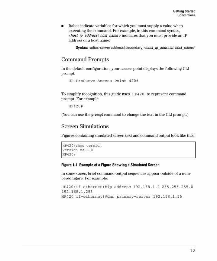
Conventions This guide uses the following conventions for command syntax and displayed information.
Command Syntax Statements Syntax: radius-server address [secondary] <host_ip_address | host_name>
■ Vertical bars ( | ) separate alternative, mutually exclusive elements.
■ Square brackets ( [ ] ) indicate optional elements.
■ Braces ( < > ) enclose required elements.
■ Braces within square brackets ( [ < > ] ) indicate a required element within an optional choice.
■ Boldface indicates use of a CLI command, part of a CLI command syntax, or other displayed element in general text. For example:
“Use the copy tftp command to download the key from a TFTP server.”
1-2
Getting Started Conventions
■ Italics indicate variables for which you must supply a value when executing the command. For example, in this command syntax, <host_ip_address | host_name > indicates that you must provide an IP address or a host name:
Syntax: radius-server address [secondary] <host_ip_address | host_name>
Command Prompts
In the default configuration, your access point displays the following CLI prompt:
HP ProCurve Access Point 420#
To simplify recognition, this guide uses HP420 to represent command prompt. For example:
HP420#
(You can use the prompt command to change the text in the CLI prompt.)
Screen Simulations
Figures containing simulated screen text and command output look like this:
HP420#show versionVersion v2.0.0HP420#
Figure 1-1. Example of a Figure Showing a Simulated Screen
In some cases, brief command-output sequences appear outside of a numbered figure. For example:
HP420(if-ethernet)#ip address 192.168.1.2 255.255.255.0 192.168.1.253HP420(if-ethernet)#dns primary-server 192.168.1.55
1-3

Getting Started Related Publications
Related Publications Installation and Getting Started Guide. Use the Installation and Get
ting Started Guide shipped with your access point to prepare for and perform the physical installation. This guide also steps you through connecting the access point to your network and assigning IP addressing, as well as describing the LED indications for correct operation and trouble analysis.
HP provides a PDF version of this guide on the Product Documentation
CD-ROM shipped with the access point. You can also download a copy from the HP ProCurve website. (See “Getting Documentation From the Web” on page 1-5.)
Release Notes. Release notes are posted on the HP ProCurve website and provide information on new software updates:
■ New features and how to configure and use them
■ Software management, including downloading software to the access point
■ Software fixes addressed in current and previous releases
To view and download a copy of the latest release notes for your access point, see “Getting Documentation From the Web” on page 1-5.
1-4

Getting Started Getting Documentation From the Web
Getting Documentation From the Web 1. Go to the HP ProCurve website at
http://www.hp.com/go/hpprocurve
2. Click on technical support.
3. Click on manuals.
4. Click on the product for which you want to view or download a manual.
2
3
4
Figure 1-2. Finding Product Manuals on the HP ProCurve Website
1-5
Getting Started Sources for More Information
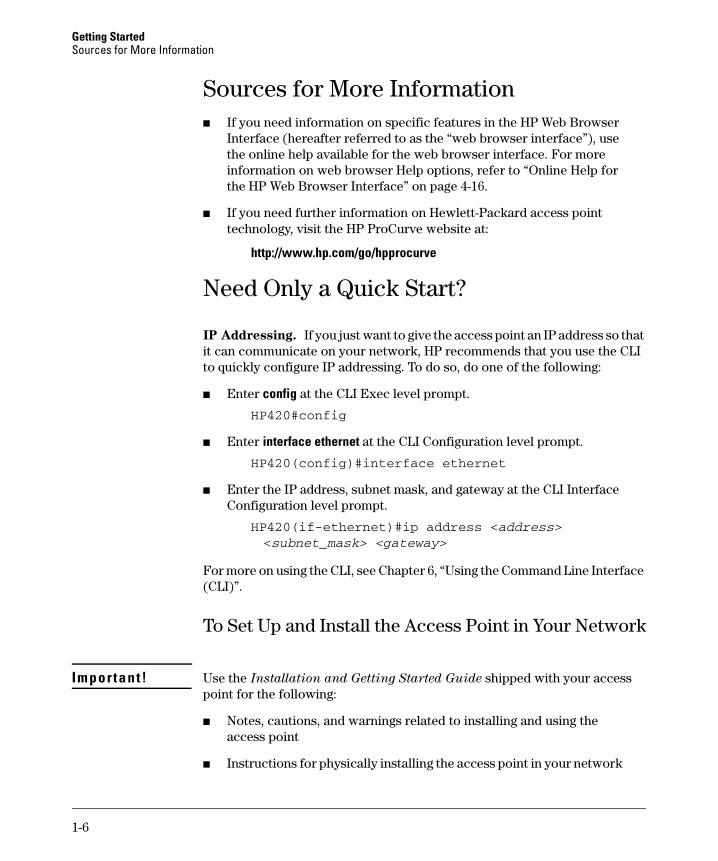
Sources for More Information ■� If you need information on specific features in the HP Web Browser
Interface (hereafter referred to as the “web browser interface”), use the online help available for the web browser interface. For more information on web browser Help options, refer to “Online Help for the HP Web Browser Interface” on page 4-16.
■� If you need further information on Hewlett-Packard access point technology, visit the HP ProCurve website at:
http://www.hp.com/go/hpprocurve
Need Only a Quick Start?
IP Addressing. If you just want to give the access point an IP address so that it can communicate on your network, HP recommends that you use the CLI to quickly configure IP addressing. To do so, do one of the following:
■ Enter config at the CLI Exec level prompt.
HP420#config
■ Enter interface ethernet at the CLI Configuration level prompt.
HP420(config)#interface ethernet
■� Enter the IP address, subnet mask, and gateway at the CLI Interface Configuration level prompt.
HP420(if-ethernet)#ip address <address><subnet_mask> <gateway>
For more on using the CLI, see Chapter 6, “Using the Command Line Interface (CLI)”.
To Set Up and Install the Access Point in Your Network
Im portant! Use the Installation and Getting Started Guide shipped with your access point for the following:
■� Notes, cautions, and warnings related to installing and using the access point
■ Instructions for physically installing the access point in your network
1-6

Getting Started Need Only a Quick Start?
■� Quickly assigning an IP address, subnet mask, and gateway, set a Manager password, and (optionally) configure other basic features.
■ Interpreting LED behavior.
For the latest version of the Installation and Getting Started Guide and other documentation for your access point, visit to the HP ProCurve website. (Refer to “Getting Documentation From the Web” on page 1-5.)
1-7

Getting Started Need Only a Quick Start?
1-8
2
Selecting a Management Interface
Contents
Overview . . . . . . . . . . . . . . . . . . . . . . . . . . . . . . . . . . . . . . . . . . . . . . . . . . . . . 2-2
Understanding Management Interfaces . . . . . . . . . . . . . . . . . . . . . . . . . 2-2
Advantages of Using the CLI . . . . . . . . . . . . . . . . . . . . . . . . . . . . . . . . . . . 2-3
Advantages of Using the HP Web Browser Interface . . . . . . . . . . . . . 2-4
2-1
Selecting a Management Interface Overview
Overview
This chapter describes the following:
■ Access Point management interfaces
■ Advantages of using each interface type
Understanding Management Interfaces Management interfaces enable you to reconfigure the access point and to monitor its status and performance. Interface types include:
■ CLI—a command line interface offering the full set of access point commands through the VT-100/ANSI console built into the access point— page 2-3
■ Web browser interface --an access point interface offering status information and a subset of access point commands through a standard web browser (such as Netscape Navigator or Microsoft Internet Explorer)— page 2-4
This manual describes how to use the CLI (chapters 3, 5 and 6), the web browser interface (chapters 4 and 5), and how to use these interfaces to configure and monitor the access point.
For information on how to access the web browser interface Help, refer to “Online Help for the HP Web Browser Interface” on page 4-16.
2-2
Selecting a Management Interface Advantages of Using the CLI
Advantages of Using the CLI
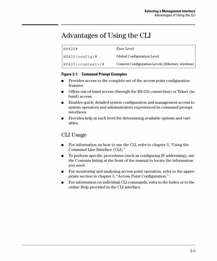
HP420# Exec Level
HP420(config)# Global Configuration Level
HP420(<context>)# Context Configuration Levels (Ethernet, wireless)
Figure 2-1. Command Prompt Examples
■ Provides access to the complete set of the access point configuration features.
■ Offers out-of-band access (through the RS-232 connection) or Telnet (in-band) access.
■ Enables quick, detailed system configuration and management access to system operators and administrators experienced in command prompt interfaces.
■ Provides help at each level for determining available options and variables.
CLI Usage
■ For information on how to use the CLI, refer to chapter 3, “Using the Command Line Interface (CLI).”
■ To perform specific procedures (such as configuring IP addressing), use the Contents listing at the front of the manual to locate the information you need.
■ For monitoring and analyzing access point operation, refer to the appropriate section in chapter 5, “Access Point Configuration.”
■ For information on individual CLI commands, refer to the Index or to the online Help provided in the CLI interface.
2-3
Selecting a Management Interface Advantages of Using the HP Web Browser Interface
Advantages of Using the HP Web Browser Interface
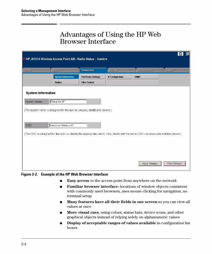
Figure 2-2. Example of the HP Web Browser Interface
■ Easy access to the access point from anywhere on the network
■ Familiar browser interface--locations of window objects consistent with commonly used browsers, uses mouse clicking for navigation, no terminal setup
■ Many features have all their fields in one screen so you can view all values at once
■ More visual cues, using colors, status bars, device icons, and other graphical objects instead of relying solely on alphanumeric values
■ Display of acceptable ranges of values available in configuration list boxes
2-4
3
Using the Command Line Interface (CLI)
Contents
Overview . . . . . . . . . . . . . . . . . . . . . . . . . . . . . . . . . . . . . . . . . . . . . . . . . . . . . 3-2
Accessing the CLI . . . . . . . . . . . . . . . . . . . . . . . . . . . . . . . . . . . . . . . . . . . . . 3-2
Using the CLI . . . . . . . . . . . . . . . . . . . . . . . . . . . . . . . . . . . . . . . . . . . . . . . . . 3-2
Privilege Level at Logon . . . . . . . . . . . . . . . . . . . . . . . . . . . . . . . . . . . . . . 3-2
Privilege Level Operation . . . . . . . . . . . . . . . . . . . . . . . . . . . . . . . . . . . . . 3-4Exec Privileges . . . . . . . . . . . . . . . . . . . . . . . . . . . . . . . . . . . . . . . . . . 3-4
How To Move Between Levels . . . . . . . . . . . . . . . . . . . . . . . . . . . . . . . . 3-6
Listing Commands and Command Options . . . . . . . . . . . . . . . . . . . . . . 3-7Listing Commands Available at Any Privilege Level . . . . . . . . . . . 3-7Command Option Displays . . . . . . . . . . . . . . . . . . . . . . . . . . . . . . . . 3-9
Configuration Commands and the Context Configuration Modes . . 3-10
CLI Control and Editing . . . . . . . . . . . . . . . . . . . . . . . . . . . . . . . . . . . . . . 3-12
3-1
Using the Command Line Interface (CLI) Overview
Overview
The CLI is a text-based command interface for configuring and monitoring the access point. The CLI gives you access to the access point’s full set of commands while providing the same password protection that is used in the web browser interface.
Accessing the CLI
The CLI is accessed through the access point console. You can access the console out-of-band by directly connecting a terminal device to the access point, or in-band by using Telnet.
Using the CLI
The CLI offers these privilege levels to simplify configuration:
1. Exec
2. Global Configuration
3. Context Configuration
N o t e CLI commands are not case-sensitive.
When you use the CLI to make a configuration change, the access point immediately saves the change to non-volatile memory. Whenever you reboot the access point, all changes made since the last reboot are retained.
Privilege Level at Logon
The access point provides a single password for the CLI. To secure management access to the access point, you must set the Manager password. Without
a Manager password configured, anyone having serial port or Telnet access
to the access point can reach all CLI command modes.
3-2
Using the Command Line Interface (CLI) Using the CLI
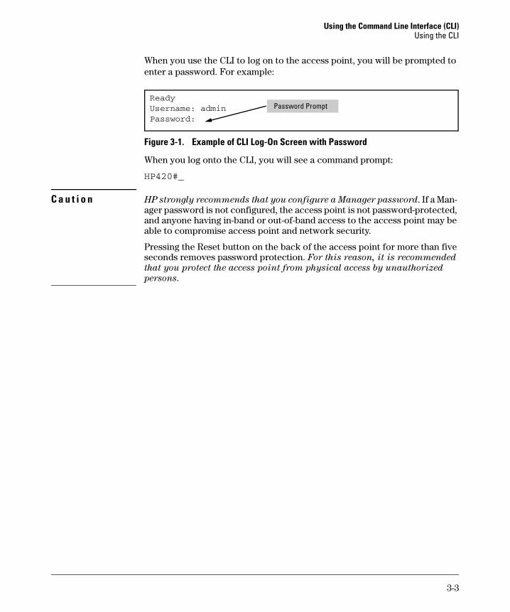
When you use the CLI to log on to the access point, you will be prompted to enter a password. For example:
Ready Username: admin Password:
Password Prompt
Figure 3-1. Example of CLI Log-On Screen with Password
When you log onto the CLI, you will see a command prompt:
HP420#_
C a u t i o n HP strongly recommends that you configure a Manager password. If a Manager password is not configured, the access point is not password-protected, and anyone having in-band or out-of-band access to the access point may be able to compromise access point and network security.
Pressing the Reset button on the back of the access point for more than five seconds removes password protection. For this reason, it is recommended
that you protect the access point from physical access by unauthorized
persons.
3-3
Using the Command Line Interface (CLI) Using the CLI
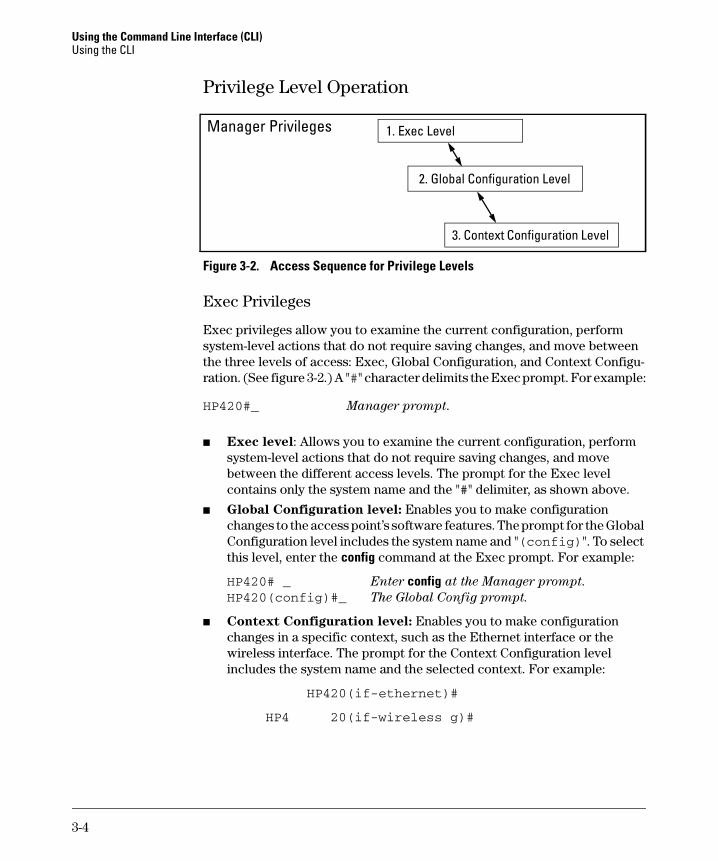
Privilege Level Operation
1. Exec Level
2. Global Configuration Level
Manager Privileges
3. Context Configuration Level
Figure 3-2. Access Sequence for Privilege Levels
Exec Privileges
Exec privileges allow you to examine the current configuration, perform system-level actions that do not require saving changes, and move between the three levels of access: Exec, Global Configuration, and Context Configuration. (See figure 3-2.) A "#" character delimits the Exec prompt. For example:
HP420#_ Manager prompt.
■ Exec level: Allows you to examine the current configuration, perform system-level actions that do not require saving changes, and move between the different access levels. The prompt for the Exec level contains only the system name and the "#" delimiter, as shown above.
■ Global Configuration level: Enables you to make configuration changes to the access point’s software features. The prompt for the Global Configuration level includes the system name and "(config)". To select this level, enter the config command at the Exec prompt. For example:
HP420# _ Enter config at the Manager prompt. HP420(config)#_ The Global Config prompt.
■ Context Configuration level: Enables you to make configuration changes in a specific context, such as the Ethernet interface or the wireless interface. The prompt for the Context Configuration level includes the system name and the selected context. For example:
HP420(if-ethernet)#
HP4 20(if-wireless g)#
3-4
Using the Command Line Interface (CLI) Using the CLI
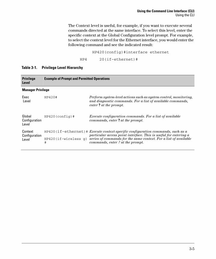
The Context level is useful, for example, if you want to execute several commands directed at the same interface. To select this level, enter the specific context at the Global Configuration level prompt. For example, to select the context level for the Ethernet interface, you would enter the following command and see the indicated result:
HP420(config)#interface ethernet
HP4 20(if-ethernet)#
Table 3-1. Privilege Level Hierarchy
Privilege Level
Example of Prompt and Permitted Operations
Manager Privilege
Exec HP420# Perform system-level actions such as system control, monitoring,
Level and diagnostic commands. For a list of available commands,
enter ? at the prompt.
Global Configuration Level
HP420(config)# Execute configuration commands. For a list of available
commands, enter ? at the prompt.
Context Configuration Level
HP420(if-ethernet)#
HP420(if-wireless g) #
Execute context-specific configuration commands, such as a particular access point interface. This is useful for entering a series of commands for the same context. For a list of available commands, enter ? at the prompt.
3-5
Using the Command Line Interface (CLI) Using the CLI
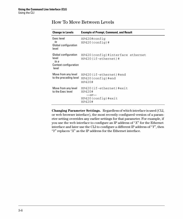
How To Move Between Levels
Change in Levels Example of Prompt, Command, and Result
Exec level to
Global configuration level
Global configuration level
to a Context configuration level
Move from any level to the preceding level
Move from any level to the Exec level
HP420#config HP420(config)#
HP420(config)#interface ethernet HP420(if-ethernet)#
HP420(if-ethernet)#end HP420(config)#end HP420#
HP420(if-ethernet)#exit HP420#
—or— HP420(config)#exit HP420#
Changing Parameter Settings. Regardless of which interface is used (CLI, or web browser interface), the most recently configured version of a parameter setting overrides any earlier settings for that parameter. For example, if you use the web interface to configure an IP address of “X” for the Ethernet interface and later use the CLI to configure a different IP address of “Y”, then “Y” replaces “X” as the IP address for the Ethernet interface.
3-6
Using the Command Line Interface (CLI) Using the CLI
Listing Commands and Command Options
At any privilege level you can:
■ List all of the commands available at that level
■ List the options for a specific command
Listing Commands Available at Any Privilege Level
At a given privilege level you can list and execute the commands that level offers. For example, at the Exec level, you can list and execute only the Exec level commands; and at the Configuration level, you can list and execute the commands available only to Configuration levels.
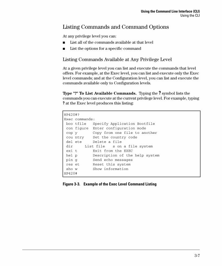
Type "?" To List Available Commands. Typing the ? symbol lists the commands you can execute at the current privilege level. For example, typing ? at the Exec level produces this listing:
HP420#? Exec commands: boo tfile Specify Application Bootfile con figure Enter configuration mode cop y Copy from one file to another cou ntry Set the country code del ete Delete a file dir List file s on a file system exi t Exit from the EXEC hel p Description of the help system pin g Send echo messages res et Reset this system sho w Show information HP420#
Figure 3-3. Example of the Exec Level Command Listing
3-7
Using the Command Line Interface (CLI) Using the CLI
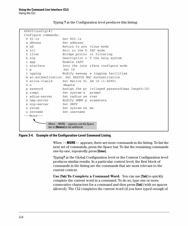
Typing ? at the Configuration level produces this listing:
HP420(config)#? Configure commands: 8 02.1x Set 802.1x a ddress Set address e nd Return to pre vious mode e xit Exit to the E XEC mode f ilter Bridge protoc ol filtering h elp Description o f the help system i app Enable IAPP i nterface Into the inte rface configure mode i p Set IP l ogging Modify messag e logging facilities m ac-authentication C Authentication n ative-vlanid Set Native VL AN ID <1-4095> n o Negate p assword Assign the pr ivileged password(max length:16) p rompt Set system's prompt r adius-server Set radius se rver s nmp-server Modify SNMP p arameters s ntp-server Set SNTP s ystem Set system na me u sername Set username ---More---
When - - MORE - - appears, use the Space bar or [Return] to list additional
Set RADIUS MA
Figure 3-4. Example of the Configuration-Level Command Listing
When - - MORE - - appears, there are more commands in the listing. To list the next set of commands, press the Space bar. To list the remaining commands one-by-one, repeatedly press [Enter].
Typing? at the Global Configuration level or the Context Configuration level produces similar results. In a particular context level, the first block of commands in the listing are the commands that are most relevant to the current context.
Use [Tab] To Complete a Command Word. You can use [Tab] to quickly complete the current word in a command. To do so, type one or more consecutive characters for a command and then press [Tab] (with no spaces allowed). The CLI completes the current word (if you have typed enough of
3-8
Using the Command Line Interface (CLI) Using the CLI
the word for the CLI to distinguish it from other possibilities). For example, at the Global Configuration level, if you press [Tab] immediately after typing "u", the CLI displays the command that begins with "u". For example:
HP420(config)#u[Tab] HP420(config)#username
Use Shorthand Entries. You can abbreviate commands and options as long as they contain enough letters to be distinguished from any other currently available commands or options.
Command Option Displays
Conventions for Command Option Displays. When you use the CLI to list options for a particular command, you will see one or more of the following conventions to help you interpret the command data:
■ Braces (< >) indicate a required choice.
■ Square brackets ([]) indicate optional elements.
■ Vertical bars (|) separate alternative, mutually exclusive options in a command.
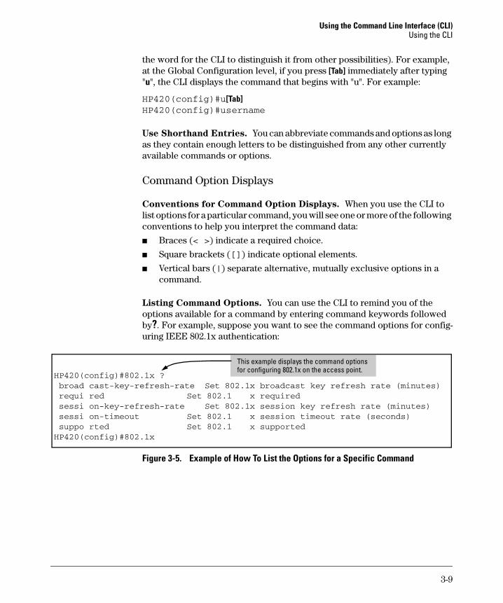
Listing Command Options. You can use the CLI to remind you of the options available for a command by entering command keywords followed by?. For example, suppose you want to see the command options for configuring IEEE 802.1x authentication:
HP420(config)#802.1x ? broad cast-key-refresh-rate x broadcast key refresh rate (minutes) requi red Set 802.1 x required sessi on-key-refresh-rate x session key refresh rate (minutes) sessi on-timeout Set 802.1 x session timeout rate (seconds) suppo rted Set 802.1 x supported HP420(config)#802.1x
This example displays the command options for configuring 802.1x on the access point.
Set 802.1
Set 802.1
Figure 3-5. Example of How To List the Options for a Specific Command
3-9
Using the Command Line Interface (CLI) Using the CLI
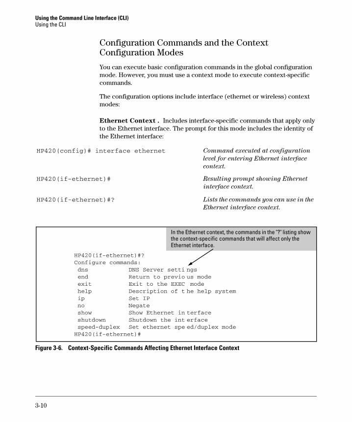
Configuration Commands and the Context Configuration Modes
You can execute basic configuration commands in the global configuration mode. However, you must use a context mode to execute context-specific commands.
The configuration options include interface (ethernet or wireless) context modes:
Ethernet Context . Includes interface-specific commands that apply only to the Ethernet interface. The prompt for this mode includes the identity of the Ethernet interface:
HP420(config)# interface ethernet
HP420(if-ethernet)#
HP420(if-ethernet)#?
Command executed at configuration
level for entering Ethernet interface
context.
Resulting prompt showing Ethernet
interface context.
Lists the commands you can use in the
Ethernet interface context.
In the Ethernet context, the commands in the "?" listing show the context-specific commands that will affect only the Ethernet interface.
HP420(if-ethernet)#? Configure commands: dns DNS Server setti ngs end Return to previo us mode exit Exit to the EXEC mode help Description of t he help system ip Set IP no Negate show Show Ethernet in terface shutdown Shutdown the int erface speed-duplex Set ethernet spe ed/duplex mode HP420(if-ethernet)#
Figure 3-6. Context-Specific Commands Affecting Ethernet Interface Context
3-10

Using the Command Line Interface (CLI) Using the CLI
Wireless Context . Includes wireless-specific commands that apply only to the wireless interface. The prompt for this mode includes the identity of the wireless interface:
HP420(config)#interface wireless g Command executed at configuration
level to enter wireless context.
HP420(if-wireless g)# Resulting prompt showing wireless
context.
HP420(if-wireless g)#? Lists commands you can use in the
wireless context.
In the wireless context, the commands in the "?" listing show the commands that will affect only the wireless interface.
HP420(if-wireless g)#? authe ntication Set authentication type beaco n-interval Set beacon interval chann el Set channel close d-system Set Closed System descr iption Set description dtim- period Set DTIM encry ption Set encryption end Return to previous mode exit Exit to the EXEC mode fragm entation-length Set fragment length help Description of the help system key Set key max-a ssociation Maximum association munber multi cast-cipher WPA Multicast cipher no Negate radio -mode Set radio mode rts-t hreshold Rts threshold show Show wireless interface shutd own Shutdown speed Speed ssid SSID trans mit-key Transmit key index trans mit-power Transmit power wpa-c lients WPA client mode wpa-m ode WPA key management mode wpa-p reshared-key WPA enter Pre-shared key wpa-p sk-type WPA enter Pre-shared key type HP420(if-wireless g)#
Figure 3-7. Context-Specific Commands Affecting Wireless Context
3-11
Using the Command Line Interface (CLI) CLI Control and Editing
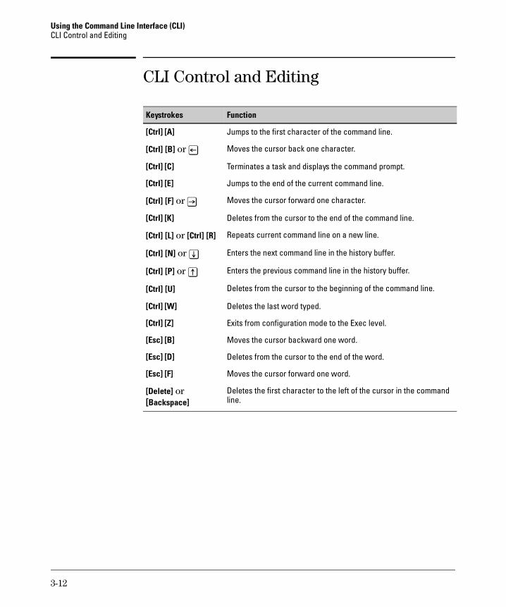
CLI Control and Editing
Keystrokes Function
[Ctrl] [A] Jumps to the first character of the command line.
[Ctrl] [B] or [<] Moves the cursor back one character.
[Ctrl] [C] Terminates a task and displays the command prompt.
[Ctrl] [E] Jumps to the end of the current command line.
[Ctrl] [F] or [>] Moves the cursor forward one character.
[Ctrl] [K] Deletes from the cursor to the end of the command line.
[Ctrl] [L] or [Ctrl] [R] Repeats current command line on a new line.
[Ctrl] [N] or [v] Enters the next command line in the history buffer.
[Ctrl] [P] or [^] Enters the previous command line in the history buffer.
[Ctrl] [U] Deletes from the cursor to the beginning of the command line.
[Ctrl] [W] Deletes the last word typed.
[Ctrl] [Z] Exits from configuration mode to the Exec level.
[Esc] [B] Moves the cursor backward one word.
[Esc] [D] Deletes from the cursor to the end of the word.
[Esc] [F] Moves the cursor forward one word.
[Delete] or Deletes the first character to the left of the cursor in the command [Backspace] line.
3-12
4
Using the HP Web Browser Interface
Contents
Overview . . . . . . . . . . . . . . . . . . . . . . . . . . . . . . . . . . . . . . . . . . . . . . . . . . . . . 4-2
General Features . . . . . . . . . . . . . . . . . . . . . . . . . . . . . . . . . . . . . . . . . . . . . . 4-3
Starting a Web Browser Interface Session with the Access Point . 4-4
Description of Browser Interface . . . . . . . . . . . . . . . . . . . . . . . . . . . . . . 4-5
The Home Page . . . . . . . . . . . . . . . . . . . . . . . . . . . . . . . . . . . . . . . . . . . . . 4-5
Support URL . . . . . . . . . . . . . . . . . . . . . . . . . . . . . . . . . . . . . . . . . . . . . . . 4-6
Tasks for Your First HP Web Browser Interface Session . . . . . . . . . 4-7
Changing the User Name and Password in the Browser Interface . . . 4-7If You Lose the User Name or Password . . . . . . . . . . . . . . . . . . . . 4-9
Setting the SSID . . . . . . . . . . . . . . . . . . . . . . . . . . . . . . . . . . . . . . . . . . . . . 4-9
Setting the Radio Channel . . . . . . . . . . . . . . . . . . . . . . . . . . . . . . . . . . . 4-10
Configuring TCP/IP Settings . . . . . . . . . . . . . . . . . . . . . . . . . . . . . . . . . 4-12
Configuring Security Settings . . . . . . . . . . . . . . . . . . . . . . . . . . . . . . . . 4-13
Online Help for the HP Web Browser Interface . . . . . . . . . . . . . . . . . 4-16
Status Reporting Features . . . . . . . . . . . . . . . . . . . . . . . . . . . . . . . . . . . . 4-17
The AP Status Window . . . . . . . . . . . . . . . . . . . . . . . . . . . . . . . . . . . . . . 4-17
Station Status . . . . . . . . . . . . . . . . . . . . . . . . . . . . . . . . . . . . . . . . . . . . . . 4-19
Event Logs . . . . . . . . . . . . . . . . . . . . . . . . . . . . . . . . . . . . . . . . . . . . . . . . 4-20
The Status Bar . . . . . . . . . . . . . . . . . . . . . . . . . . . . . . . . . . . . . . . . . . . . . 4-21
4-1

Using the HP Web Browser Interface Overview
Overview
The HP web browser interface built into the access point lets you easily access the access point from a browser-based PC on your network. This lets you do the following:
■ Make configuration changes to the access point
■ Control access to the management interface by configuring a user name and password
■ Maintain access security for wireless clients using WPA or WEP shared keys
■ Encrypt data communications between clients and access points using various algorithms, including DES (default by WEP), TKIP or AES
■ Optimize your network uptime by using the System Log
This chapter covers the following:
■ General features (page 4-3)
■ Starting a web browser interface session (page 4-4)
■ Tasks for your first web browser interface session (page 4-7)
• Configuring a user name and password for management access in the web browser interface (page 4-7)
• Set the access point Service Set Identifier (page 4-9)
• Enable radio communications and select a channel (page 4-10)
• Changing IP settings (page 4-12)
• Setting wireless network security (page 4-13)
• Getting access to online help for the web browser interface (page 4-16)
■ Description of the web browser interface
• The Home Page (page 4-5)
• The Support URL (page 4-6)
■ Status Reporting Features
• The AP Status window (page 4-17)
• Station status (page 4-19)
• Event logs (page 4-20)
• The Status bar (page 4-21)
4-2

Using the HP Web Browser Interface General Features
General Features
The access point includes these web browser interface features:
Access Point Configuration:
• System identification and service set identifier
• IP settings via manual configuration or DHCP
• RADIUS client identification
• Wireless client authentication via IEEE 802.1x
• Filter control between wireless clients, between wireless clients and the management interface, or for specified protocol types
• SNMP community strings and trap managers
• Usernames and passwords
• Firmware upgrade and system reset
• System log server and log message levels
• SNTP client and manual clock configuration
Access Point Radio Interface:
• Radio signal parameters
• Wireless client security, including WEP and WPA
Access Point status
• System configuration
• Wireless configuration
• Station status
• Event logs
4-3
Using the HP Web Browser Interface Starting a Web Browser Interface Session with the Access Point
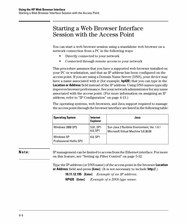
Starting a Web Browser Interface Session with the Access Point
You can start a web browser session using a standalone web browser on a network connection from a PC in the following ways:
• Directly connected to your network
• Connected through remote access to your network
This procedure assumes that you have a supported web browser installed on your PC or workstation, and that an IP address has been configured on the access point. If you are using a Domain Name Server (DNS), your device may have a name associated with it (for example, hp420) that you can type in the Location or Address field instead of the IP address. Using DNS names typically improves browser performance. See your network administrator for any name associated with the access point. (For more information on assigning an IP address, refer to “IP Configuration” on page 4-13.)
The operating systems, web browsers, and Java support required to manage the access point through the browser interface are listed in the following table:
Operating System Internet Explorer
Java
Windows 2000 SP3 5.01, SP1 6.0, SP1
Sun Java 2 Runtime Environment, Ver. 1.4.1 Microsoft Virtual Machine 5.0.38.09
Windows XP Professional Hotfix SP2
6.0, SP1
N o t e : IP management can be limited to access from the Ethernet interface. For more on this feature, see “Setting up Filter Control” on page 5-32.
Type the IP address (or DNS name) of the access point in the browser Location or Address field and press [Enter]. (It is not necessary to include http://.)
10.11.12.195 [Enter] Example of an IP address.
HP420 [Enter] Example of a DNS-type name.
4-4
Using the HP Web Browser Interface Description of Browser Interface
Description of Browser Interface
Browser elements covered in this section include:
■ The Home Page (below)
■ The Support URL (page 4-6)
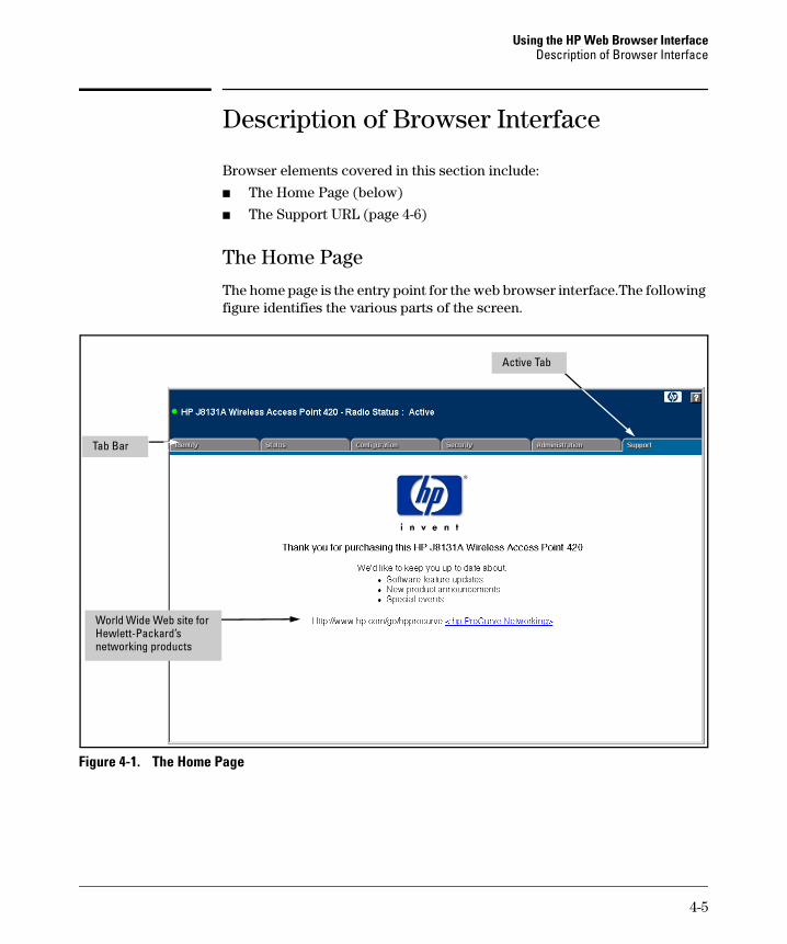
The Home Page
The home page is the entry point for the web browser interface.The following figure identifies the various parts of the screen.
Tab Bar
Active Tab
World Wide Web site for Hewlett-Packard’s networking products
Figure 4-1. The Home Page
4-5
Using the HP Web Browser Interface Description of Browser Interface
Support URL
The home page for the access point’s web browser interface is the Support tab. This page provides the following URL:
http://www.hp.com/go/hpprocurve
which is the World Wide Web site for Hewlett-Packard’s networking products. Click on the link on this page and you can get to support information regarding your access point, including white papers, firmware updates, and more.
4-6

Using the HP Web Browser Interface Tasks for Your First HP Web Browser Interface Session
Tasks for Your First HP Web Browser Interface Session
The first time you access the web browser interface, there are a number of basic tasks that you should perform:
■ Set the Manager user name and password
■ Set the access point Service Set Identifier (SSID)
■ Enable radio communications and select a channel
■ Change TCP/IP settings
■ Set radio security options
Changing the User Name and Password in the Browser Interface
You may want to change both the user name and password to enhance access security for the management interface on your access point. A single user name and password allow full read/write access to the web browser interface.
N o t e If you want security beyond that achieved with user names and passwords, you can disable access to the web browser interface. This is done by executing no ip http server at the Global Configuration level command prompt in the CLI. Then, management access is only from the CLI through the console port on the access point.
To set the user name or password with the web browser interface:
1. Click the Administration tab and then the [Change Password] button to display the Change Password menu.
4-7
Using the HP Web Browser Interface Tasks for Your First HP Web Browser Interface Session
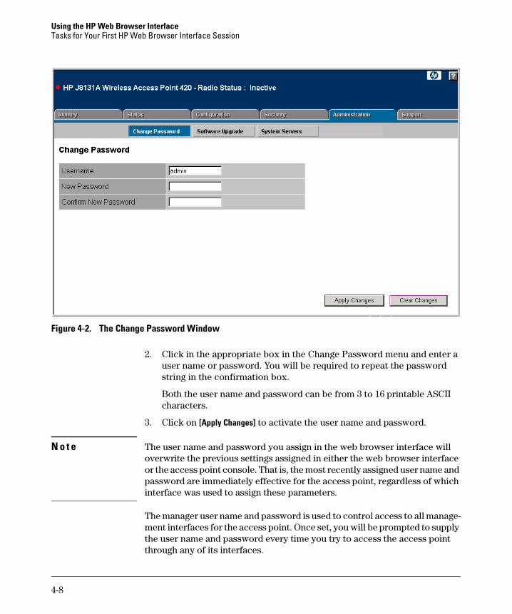
Figure 4-2. The Change Password Window
2. Click in the appropriate box in the Change Password menu and enter a user name or password. You will be required to repeat the password string in the confirmation box.
Both the user name and password can be from 3 to 16 printable ASCII characters.
3. Click on [Apply Changes] to activate the user name and password.
N o t e The user name and password you assign in the web browser interface will overwrite the previous settings assigned in either the web browser interface or the access point console. That is, the most recently assigned user name and password are immediately effective for the access point, regardless of which interface was used to assign these parameters.
The manager user name and password is used to control access to all management interfaces for the access point. Once set, you will be prompted to supply the user name and password every time you try to access the access point through any of its interfaces.
4-8
Using the HP Web Browser Interface Tasks for Your First HP Web Browser Interface Session
If You Lose the User Name or Password
If you lose the user name or password, you can clear them by pressing the Reset button on the back of the access point for at least five seconds. This
action deletes the password and resets the user name to the factory default
settings for all of the access point’s interfaces. All configuration information
is reset to the factory default values, including:
■ User name and password
■ Console event log (cleared)
■ Network counters (reset to zero)
■ Configured IP address
C a u t i o n The Reset button is provided for your convenience, but its presence means that if you are concerned with the security of the access point configuration and operation, you should make sure the access point is installed in a secure location.
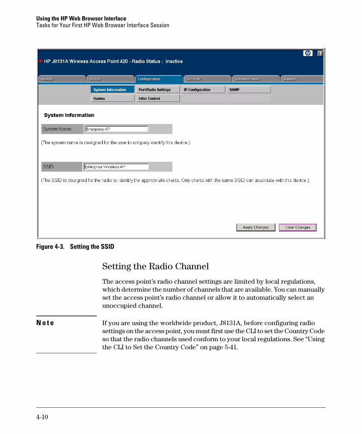
Setting the SSID
The Service Set IDentifier (SSID) is a recognizable text string that identifies the wireless network. All wireless clients that want to connect to the network through the access point must set their SSIDs to the same as that of the access point.
To set the access point SSID, click the Configuration tab and then the [System Information] button. Enter a text string up to 32 characters in the SSID box. Click the [Apply Changes] button to save the setting.
4-9
Using the HP Web Browser Interface Tasks for Your First HP Web Browser Interface Session
Figure 4-3. Setting the SSID
Setting the Radio Channel
The access point’s radio channel settings are limited by local regulations, which determine the number of channels that are available. You can manually set the access point’s radio channel or allow it to automatically select an unoccupied channel.
N o t e If you are using the worldwide product, J8131A, before configuring radio settings on the access point, you must first use the CLI to set the Country Code so that the radio channels used conform to your local regulations. See “Using the CLI to Set the Country Code” on page 5-41.
4-10
Using the HP Web Browser Interface Tasks for Your First HP Web Browser Interface Session
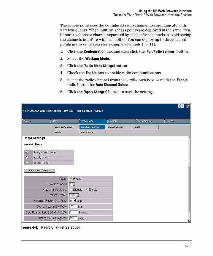
The access point uses the configured radio channel to communicate with wireless clients. When multiple access points are deployed in the same area, be sure to choose a channel separated by at least five channels to avoid having the channels interfere with each other. You can deploy up to three access points in the same area (for example, channels 1, 6, 11).
1. Click the Configuration tab, and then click the [Port/Radio Settings] button.
2. Select the Working Mode.
3. Click the [Radio Mode Change] button.
4. Check the Enable box to enable radio communications.
5. Select the radio channel from the scroll-down box, or mark the Enable radio button for Auto Channel Select.
6. Click the [Apply Changes] button to save the settings.
Figure 4-4. Radio Channel Selection
4-11
Using the HP Web Browser Interface Tasks for Your First HP Web Browser Interface Session
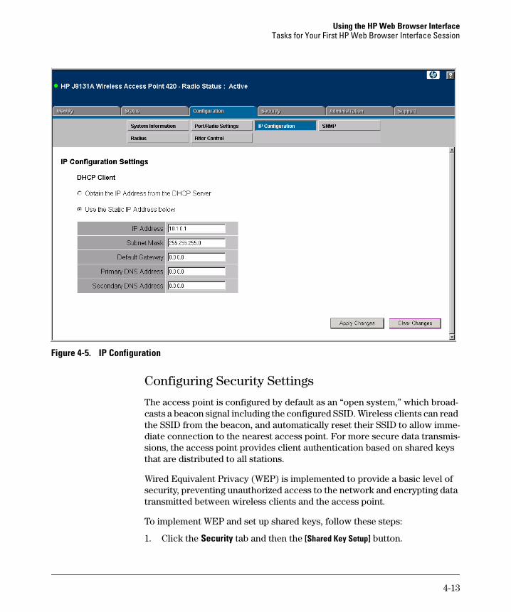
Configuring TCP/IP Settings
You can use the web browser interface to manage the access point only if it already has an IP address that is reachable through your network. You can set an initial IP address for the access point by using the CLI interface. After you have network access to the access point, you can then use the web browser interface to modify the initial IP configuration.
1. Click the Configuration tab, and then click the [IP Configuration] button.
2. Select either Obtain the IP Address from the DHCP Server or Use the Static IP Address below.
3. If you select to use a static IP address, you must manually enter the IP address and subnet mask.
4. If a management station exists on another network segment, enter the IP address of a gateway that can route traffic between these segments.
5. Enter the IP address for the primary and secondary DNS servers to be used for host-name to IP address resolution.
6. Click the [Apply Changes] button.
N o t e If you change the IP address using the web interface, you must log in again using the new address.
4-12
Using the HP Web Browser Interface Tasks for Your First HP Web Browser Interface Session
Figure 4-5. IP Configuration
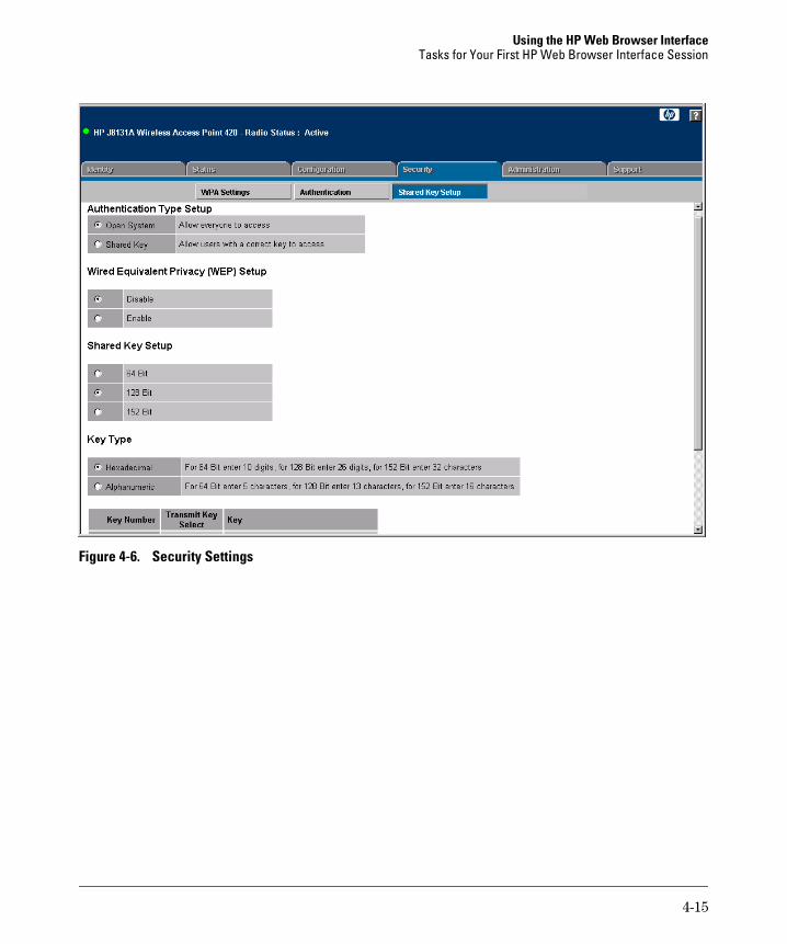
Configuring Security Settings
The access point is configured by default as an “open system,” which broad-casts a beacon signal including the configured SSID. Wireless clients can read the SSID from the beacon, and automatically reset their SSID to allow immediate connection to the nearest access point. For more secure data transmissions, the access point provides client authentication based on shared keys that are distributed to all stations.
Wired Equivalent Privacy (WEP) is implemented to provide a basic level of security, preventing unauthorized access to the network and encrypting data transmitted between wireless clients and the access point.
To implement WEP and set up shared keys, follow these steps:
1. Click the Security tab and then the [Shared Key Setup] button.
4-13
Using the HP Web Browser Interface Tasks for Your First HP Web Browser Interface Session
2. Set the Authentication Type to Shared Key to require authentication based on a shared key that has been distributed to all stations.
3. Enable Wired Equivalency Setup (WEP) to encrypt transmissions passing between wireless clients and the access point.
4. To configure the shared key, select 64-bit, 128-bit, or 152-bit key size, and enter a hexadecimal or ASCII string of the appropriate length.
5. Click the [Apply Changes] button.
N o t e The WEP settings must be the same on each client in your wireless network.
WEP is the security protocol initially specified in the IEEE 802.11 standard for wireless communications. While WEP provides a margin of security for environments with light network traffic, it is not sufficient for enterprise use where highly-sensitive data is transmitted.
For more robust wireless security, you should consider implementing other features supported by the access point. Wi-Fi Protected Access (WPA) and IEEE 802.1x provide improved data encryption and user authentication. See “Configuring Wireless Security” on page 5-45.
4-14
Using the HP Web Browser Interface Tasks for Your First HP Web Browser Interface Session
Figure 4-6. Security Settings
4-15
Using the HP Web Browser Interface Tasks for Your First HP Web Browser Interface Session
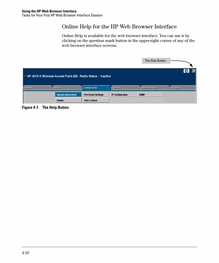
Online Help for the HP Web Browser Interface
Online Help is available for the web browser interface. You can use it by clicking on the question mark button in the upper-right corner of any of the web browser interface screens.
The Help Button
Figure 4-7. The Help Button
4-16
Using the HP Web Browser Interface Status Reporting Features
Status Reporting Features
Browser elements covered in this section include:
■ The AP Status window (below)
■ Station status (page 4-19)
■ Event logs (page 4-20)
■ The Status bar (page 4-21)
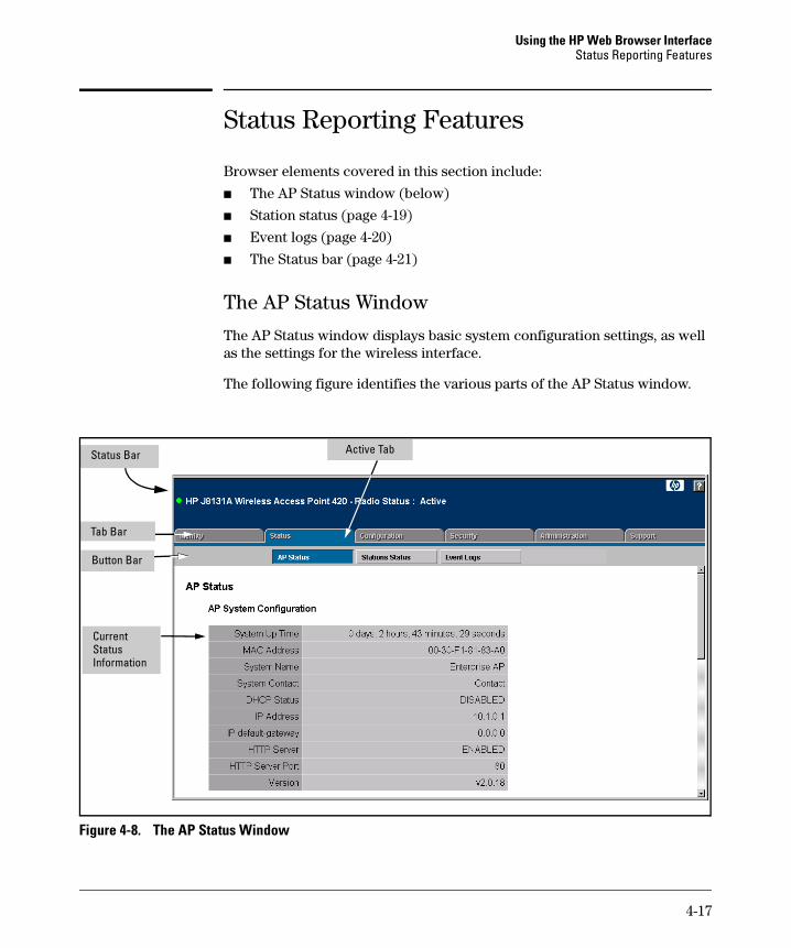
The AP Status Window
The AP Status window displays basic system configuration settings, as well as the settings for the wireless interface.
The following figure identifies the various parts of the AP Status window.
Active Tab
Button Bar
Tab Bar
Status Bar
Current Status Information
Figure 4-8. The AP Status Window
4-17
Using the HP Web Browser Interface Status Reporting Features
AP System Configuration. The AP System Configuration table displays the basic system configuration settings:
■ System Up Time: Length of time the access point has been up.
■ MAC Address: The physical layer address for this device.
■ System Name: Name assigned to this system.
■ System Contact: Administrator responsible for the system.
■ DHCP Status: Shows if IP configuration is via a DHCP server.
■ IP Address: IP address of the management interface for this device.
■ IP Default Gateway: IP address of the gateway router between this device and management stations that exist on other network segments.
■ HTTP Server: Shows if management access via HTTP is enabled.
■ HTTP Server Port: Shows the TCP port used by the HTTP interface.
■ Version: Shows the version number for the runtime code.
AP Wireless Configuration. The AP Wireless Configuration table displays the following wireless interface settings:
■ SSID: The service set identifier that identifies this wireless group.
■ Radio: Indicates if the access point is operating in 802.11b, 802.11g, or mixed (b &g) mode.
■ Radio Status: Indicates if the access point radio is enabled or disabled.
■ Auto Channel Select: Indicates if the access point automatically selects an unoccupied radio channel.
■ Radio Channel: The radio channel through which the access point communicates with wireless clients.
■ Radio Encryption: The key size used for data encryption.
■ Radio Authentication Type: Shows if open system or shared key authentication is used.
■ 802.1x: Shows if IEEE 802.1x access control for wireless clients is enabled.
AP Ethernet Configuration. The AP Ethernet Configuration table displays the following ethernet interface settings:
■ Subnet Mask: The mask that identifies the host address bits used for routing to specific subnets.
■ Primary DNS: The IP address of the primary Domain Name Server on the network.
■ Secondary DNS: The IP address of the secondary Domain Name Server on the network.
4-18
Using the HP Web Browser Interface Status Reporting Features
■ Speed-Duplex: The operating speed and duplex mode of the access point’s RJ-45 Ethernet interface.
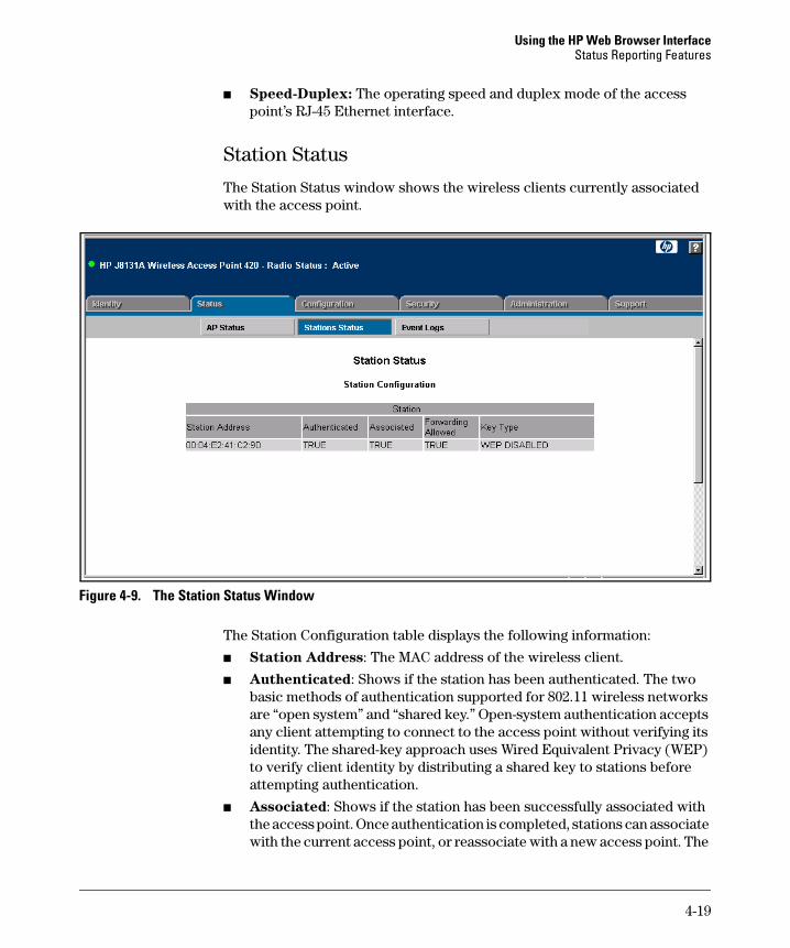
Station Status
The Station Status window shows the wireless clients currently associated with the access point.
Figure 4-9. The Station Status Window
The Station Configuration table displays the following information:
■ Station Address: The MAC address of the wireless client.
■ Authenticated: Shows if the station has been authenticated. The two basic methods of authentication supported for 802.11 wireless networks are “open system” and “shared key.” Open-system authentication accepts any client attempting to connect to the access point without verifying its identity. The shared-key approach uses Wired Equivalent Privacy (WEP) to verify client identity by distributing a shared key to stations before attempting authentication.
■ Associated: Shows if the station has been successfully associated with the access point. Once authentication is completed, stations can associate with the current access point, or reassociate with a new access point. The
4-19
Using the HP Web Browser Interface Status Reporting Features
association procedure allows the wireless system to track the location of each mobile client, and ensures that frames destined for each client are forwarded to the appropriate access point.
■ Forwarding Allowed: If 802.1x is being used shows if the station has passed 802.1x authentication and is now allowed to forward traffic to the access point. If authentication is not required this value is TRUE for all clients.
■ Key Type: Displays one of the following:
• WEP Disabled: The client is not using Wired Equivalent Privacy (WEP) encryption keys.
• Dynamic WEP: The client is using Wi-Fi Protected Access (enterprise or pre-shared key mode) or using 802.1x authentication with dynamic keying.
• Static WEP: The client is using static WEP keys for encryption.
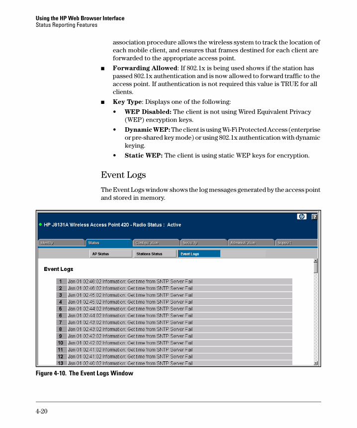
Event Logs
The Event Logs window shows the log messages generated by the access point and stored in memory.
Figure 4-10. The Event Logs Window
4-20
Using the HP Web Browser Interface Status Reporting Features
The Event Logs table displays the following information:
■ Log Time: The time the log message was generated.
■ Event Level: The logging level associated with this message. For a description of the various levels, see “Enabling System Logging” on page 5-17.
■ Event Message: The content of the log message.
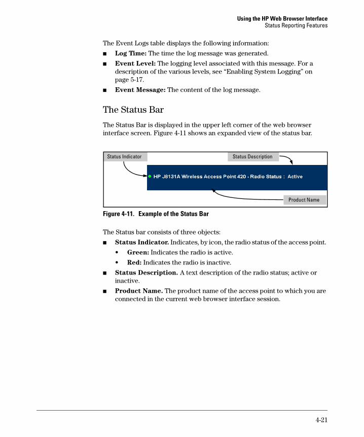
The Status Bar
The Status Bar is displayed in the upper left corner of the web browser interface screen. Figure 4-11 shows an expanded view of the status bar.
Status Indicator Status Description
Product Name
Figure 4-11. Example of the Status Bar
The Status bar consists of three objects:
■ Status Indicator. Indicates, by icon, the radio status of the access point.
• Green: Indicates the radio is active.
• Red: Indicates the radio is inactive.
■ Status Description. A text description of the radio status; active or inactive.
■ Product Name. The product name of the access point to which you are connected in the current web browser interface session.
4-21

Using the HP Web Browser Interface Status Reporting Features
4-22

5
Access Point Configuration
Contents
Overview . . . . . . . . . . . . . . . . . . . . . . . . . . . . . . . . . . . . . . . . . . . . . . . . . . . . . 5-2
Modifying System Management Access . . . . . . . . . . . . . . . . . . . . . . . . . 5-3
Web: Setting User Names and Passwords . . . . . . . . . . . . . . . . . . . . . . . 5-3
CLI: Setting User Names and Passwords . . . . . . . . . . . . . . . . . . . . . . . . 5-4
Modifying System Information . . . . . . . . . . . . . . . . . . . . . . . . . . . . . . . . . 5-5
Web: Setting the System Name and SSID . . . . . . . . . . . . . . . . . . . . . . . . 5-5
CLI: Setting the System Name and SSID . . . . . . . . . . . . . . . . . . . . . . . . 5-6
Configuring IP Settings . . . . . . . . . . . . . . . . . . . . . . . . . . . . . . . . . . . . . . . . 5-9
Web: Configuring IP Settings Statically or via DHCP . . . . . . . . . . . . . . 5-9
CLI: Configuring IP Settings Statically or via DHCP . . . . . . . . . . . . . . 5-11
Configuring SNMP . . . . . . . . . . . . . . . . . . . . . . . . . . . . . . . . . . . . . . . . . . . 5-13
Web: Setting SNMP Parameters . . . . . . . . . . . . . . . . . . . . . . . . . . . . . . 5-13
CLI: Setting SNMP Parameters . . . . . . . . . . . . . . . . . . . . . . . . . . . . . . . 5-15
Enabling System Logging . . . . . . . . . . . . . . . . . . . . . . . . . . . . . . . . . . . . . 5-17
Web: Setting Logging Parameters . . . . . . . . . . . . . . . . . . . . . . . . . . . . . 5-18
CLI: Setting Logging Parameters . . . . . . . . . . . . . . . . . . . . . . . . . . . . . . 5-19
Configuring SNTP . . . . . . . . . . . . . . . . . . . . . . . . . . . . . . . . . . . . . . . . . . . . 5-21
Web: Setting SNTP Parameters . . . . . . . . . . . . . . . . . . . . . . . . . . . . . . . 5-21
CLI: Setting SNTP Parameters . . . . . . . . . . . . . . . . . . . . . . . . . . . . . . . . 5-23
Configuring Ethernet Interface Parameters . . . . . . . . . . . . . . . . . . . 5-25
Web: Setting Ethernet Interface Parameters . . . . . . . . . . . . . . . . . . . . 5-25
CLI: Setting Ethernet Interface Parameters . . . . . . . . . . . . . . . . . . . . . 5-26
Configuring RADIUS Client Authentication . . . . . . . . . . . . . . . . . . . . 5-28
Web: Setting RADIUS Server Parameters . . . . . . . . . . . . . . . . . . . . . . 5-28
CLI: Setting RADIUS Server Parameters . . . . . . . . . . . . . . . . . . . . . . . 5-30
Setting up Filter Control . . . . . . . . . . . . . . . . . . . . . . . . . . . . . . . . . . . . . 5-32
Web: Enabling VLAN Support and Setting Filters . . . . . . . . . . . . . . . . 5-33
CLI: Enabling VLAN Support and Setting Filters . . . . . . . . . . . . . . . . 5-35
5-1
Access Point Configuration Overview
Modifying Radio Settings . . . . . . . . . . . . . . . . . . . . . . . . . . . . . . . . . . . . . 5-37
Web: Modifying the Radio Working Mode and Settings . . . . . . . . . . . 5-37
CLI: Modifying the Radio Working Mode and Settings . . . . . . . . . . . . 5-40
Configuring Wireless Security . . . . . . . . . . . . . . . . . . . . . . . . . . . . . . . . 5-45
Web: Configuring WPA Settings . . . . . . . . . . . . . . . . . . . . . . . . . . . . . . 5-48
CLI: Configuring WPA Settings . . . . . . . . . . . . . . . . . . . . . . . . . . . . . . . 5-51
Web: Configuring MAC Address Authentication . . . . . . . . . . . . . . . . . 5-53
CLI: Configuring MAC Address Authentication . . . . . . . . . . . . . . . . . 5-55
Web: Configuring IEEE 802.1x . . . . . . . . . . . . . . . . . . . . . . . . . . . . . . . 5-57
CLI: Configuring IEEE 802.1x . . . . . . . . . . . . . . . . . . . . . . . . . . . . . . . . 5-59
Web: Setting up WEP Shared-Keys . . . . . . . . . . . . . . . . . . . . . . . . . . . . 5-61
CLI: Setting up WEP Shared-Keys . . . . . . . . . . . . . . . . . . . . . . . . . . . . . 5-63
Overview
This Chapter describes how to:
■ View and modify the configuration for system management access
■ View and modify access point system information
■ Configure IP settings
■ Configure SNMP settings
■ Configure SNTP client and manual clock
■ Set up RADIUS client authentication
■ Set up filter control between wireless clients, between wireless clients and the management interface, or for specified protocol types
■ Modify radio settings
■ Configure wireless security
5-2
Access Point Configuration Modifying System Management Access
Modifying System Management Access
Management access to the access point’s web and CLI interface is controlled through a single user name and password. You can also gain additional in-band access security by using control filters (see “Setting up Filter Control” on page 5-32).
C a u t i o n HP strongly recommends that you configure a new Manager password and
not use the default. If a Manager password is not configured, then the access point is not password-protected, and anyone having in-band or out-of-band access to the access point may be able to compromise access point and network security.
Pressing the Reset button on the back of the access point for more than five seconds removes password protection. For this reason, it is recommended
that you protect the access point from physical access by unauthorized
persons.
Web: Setting User Names and Passwords
The Change Password window enables the access point’s management user name and password to be set.
The web interface enables you to modify these parameters:
■ Username: The name of the user. The default name is “admin.” (Length: 3-16 printable ASCII characters, case sensitive.)
■ New Password: The password for management access. (Length: 3-16 printable ASCII characters, case sensitive) There is no default password.
To Set a User Name and Password:
1. Select the Configuration tab.
2. Click the [Change Password] button.
3. Type a new user name in the Username text field.
4. Type a password in the New Password text field.
5. Type the password again in the Confirm New Password text field.
6. Click the [Apply Changes] button.
5-3
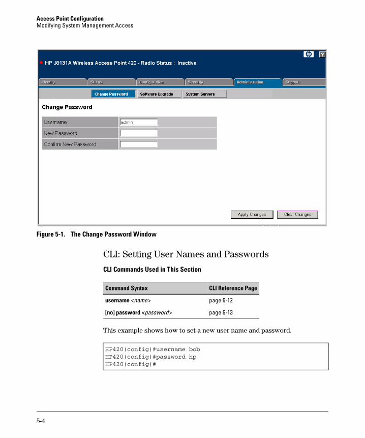
Access Point Configuration Modifying System Management Access
Figure 5-1. The Change Password Window
CLI: Setting User Names and Passwords
CLI Commands Used in This Section
Command Syntax CLI Reference Page
username <name> page 6-12
[no] password <password> page 6-13
This example shows how to set a new user name and password.
HP420(config)#username bobHP420(config)#password hpHP420(config)#
5-4
Access Point Configuration Modifying System Information
Modifying System Information
The access point’s system information parameters can be left at their default settings. However, modifying these parameters can help you to more easily distinguish one device from another in your network.
You should set a Service Set Identification (SSID) to identify the wireless network service provided by the access point. Only clients with the same SSID can associate with the access point.
Web: Setting the System Name and SSID
To modify the access point’s system name and radio Service Set Identification (SSID), use the System Information window on the Configuration tab.
The web interface enables you to modify these parameters:
■ System Name: An alias for the access point only, enabling the device to be uniquely identified on the network. Users can enter a maximum of 32 characters as a System Name.
■ SSID: The name of the basic service set provided by the access point. Clients that want to connect to the network through the access point must set their SSIDs to the same as that of the access point. (Range: 1 - 32 characters)
To Set a System Name and SSID:
1. Select the Configuration tab.
2. Click the [System Information] button.
3. Type a name to identify the access point in the System Name text field.
4. Type an identification string in the SSID text field.
5. Click the [Apply Changes] button.
5-5
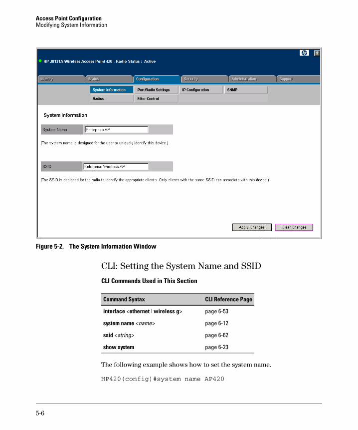
Access Point Configuration Modifying System Information
Figure 5-2. The System Information Window
CLI: Setting the System Name and SSID
CLI Commands Used in This Section
Command Syntax CLI Reference Page
interface <ethernet | wireless g> page 6-53
system name <name> page 6-12
ssid <string> page 6-62
show system page 6-23
The following example shows how to set the system name.
HP420(config)#system name AP420
5-6
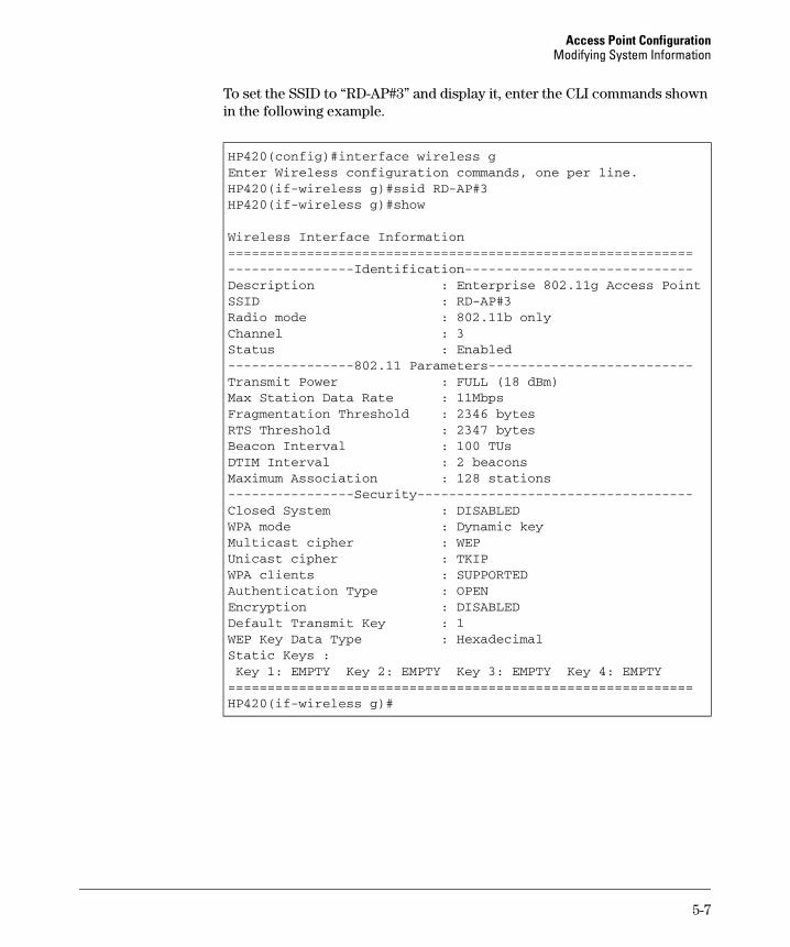
Access Point Configuration Modifying System Information
To set the SSID to “RD-AP#3” and display it, enter the CLI commands shown in the following example.
HP420(config)#interface wireless gEnter Wireless configuration commands, one per line.HP420(if-wireless g)#ssid RD-AP#3HP420(if-wireless g)#show
Wireless Interface Information===========================================================----------------Identification-----------------------------Description : Enterprise 802.11g Access PointSSID : RD-AP#3Radio mode : 802.11b onlyChannel : 3Status : Enabled----------------802.11 Parameters--------------------------Transmit Power : FULL (18 dBm)Max Station Data Rate : 11MbpsFragmentation Threshold : 2346 bytesRTS Threshold : 2347 bytesBeacon Interval : 100 TUsDTIM Interval : 2 beaconsMaximum Association : 128 stations----------------Security-----------------------------------Closed System : DISABLEDWPA mode : Dynamic keyMulticast cipher : WEPUnicast cipher : TKIPWPA clients : SUPPORTEDAuthentication Type : OPENEncryption : DISABLEDDefault Transmit Key : 1WEP Key Data Type : HexadecimalStatic Keys :Key 1: EMPTY Key 2: EMPTY Key 3: EMPTY Key 4: EMPTY
===========================================================HP420(if-wireless g)#
5-7
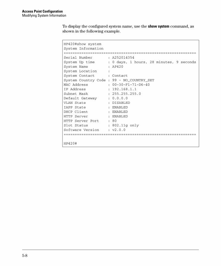
Access Point Configuration Modifying System Information
To display the configured system name, use the show system command, as shown in the following example.
HP420#show systemSystem Information============================================================Serial Number : A252014354System Up time : 0 days, 1 hours, 28 minutes, 9 secondsSystem Name : AP420System Location :System Contact : ContactSystem Country Code : 99 - NO_COUNTRY_SETMAC Address : 00-30-F1-71-D6-40IP Address : 192.168.1.1Subnet Mask : 255.255.255.0Default Gateway : 0.0.0.0VLAN State : DISABLEDIAPP State : ENABLEDDHCP Client : ENABLEDHTTP Server : ENABLEDHTTP Server Port : 80Slot Status : 802.11g onlySoftware Version : v2.0.0============================================================
HP420#
5-8
Access Point Configuration Configuring IP Settings
Configuring IP Settings
Configuring the access point with an IP address expands your ability to manage the access point and use its features. A number of access point features depend on IP addressing to operate.
N o t e You can use the web browser interface to access IP addressing only if the access point already has an IP address that is reachable through your network.
By default, the access point is configured to automatically receive IP addressing on the default VLAN from a Dynamic Host Configuration Protocol (DHCP) server. However, if you are not using a DHCP server to configure IP addressing, use the CLI to manually configure the initial IP values. After you have network access to the access point, you can use the web browser interface to modify the initial IP configuration, if needed.
N o t e If there is no DHCP server on your network, or DHCP fails, the access point will automatically start up with a default IP address of 192.168.1.1.
Web: Configuring IP Settings Statically or via DHCP
The IP Configuration window on the Configuration tab enables the DHCP client to be enabled or the Transmission Control Protocol/Internet Protocol (TCP/ IP) settings to be manually specified.
The web interface enables you to modify these parameters:
■ Obtain the IP Address from the DHCP Server: The DHCP client is enabled. The IP address, subnet mask, default gateway, and Domain Name Server (DNS) address are dynamically assigned to the access point by the network DHCP server.
■ Use the Static IP Address Below: The DHCP client is disabled. The IP address settings are configured manually.
• IP Address: The IP address of the access point. Valid IP addresses consist of four decimal numbers, 0 to 255, separated by periods.
• Subnet Mask: The mask that identifies the host address bits used for routing to specific subnets.
• Default Gateway: The default gateway is the IP address of the nexthop gateway router for the access point, which is used if the requested destination address is not on the local subnet.
5-9

Access Point Configuration Configuring IP Settings
• Primary and Secondary DNS Address: The IP address of Domain Name Servers on the network. A DNS maps numerical IP addresses to domain names and can be used to identify network hosts by familiar names instead of the IP addresses.
To Enable the DHCP Client:
1. Select the Configuration tab.
2. Click the [IP Configuration] button.
3. Select Obtain the IP Address from the DHCP Server.
4. Click the [Apply Changes] button.
To Configure IP Settings Manually:
1. Select the Configuration tab.
2. Click the [IP Configuration] button.
3. Select Use the Static IP Address below.
4. Type the IP address and the subnet mask in the text fields provided.
5. (Optional) If you have management stations, DNS, Radius, or other network servers located on another subnet, type the IP address of the default gateway router in the text field provided. Otherwise, leave the address as all zeros (0.0.0.0).
6. (Optional) If you have one or more DNS servers located on the local network, type the IP addresses in the text fields provided. Otherwise, leave the addresses as all zeros (0.0.0.0).
7. Click the [Apply Changes] button.
5-10
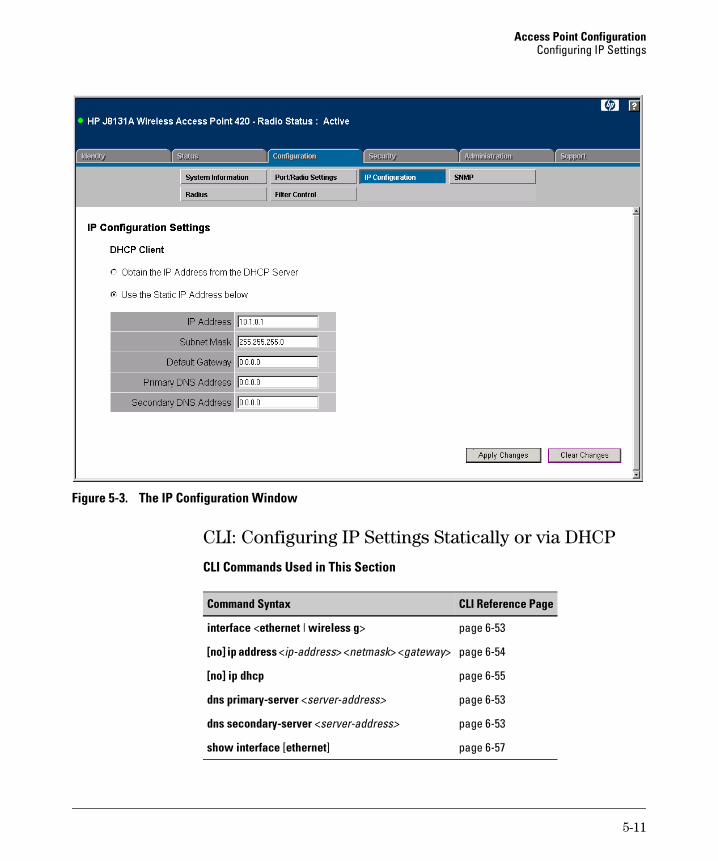
Access Point Configuration Configuring IP Settings
Figure 5-3. The IP Configuration Window
CLI: Configuring IP Settings Statically or via DHCP
CLI Commands Used in This Section
Command Syntax CLI Reference Page
interface <ethernet | wireless g> page 6-53
[no] ip address <ip-address> <netmask> <gateway> page 6-54
[no] ip dhcp page 6-55
dns primary-server <server-address> page 6-53
dns secondary-server <server-address> page 6-53
show interface [ethernet] page 6-57
5-11
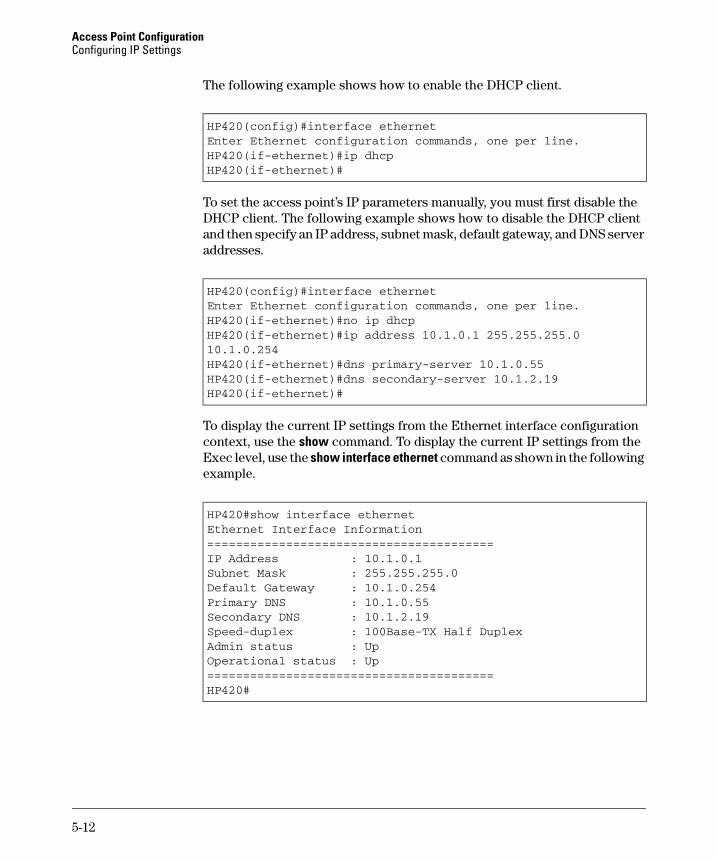
Access Point Configuration Configuring IP Settings
The following example shows how to enable the DHCP client.
HP420(config)#interface ethernetEnter Ethernet configuration commands, one per line.HP420(if-ethernet)#ip dhcpHP420(if-ethernet)#
To set the access point’s IP parameters manually, you must first disable the DHCP client. The following example shows how to disable the DHCP client and then specify an IP address, subnet mask, default gateway, and DNS server addresses.
HP420(config)#interface ethernetEnter Ethernet configuration commands, one per line.HP420(if-ethernet)#no ip dhcpHP420(if-ethernet)#ip address 10.1.0.1 255.255.255.0 10.1.0.254HP420(if-ethernet)#dns primary-server 10.1.0.55HP420(if-ethernet)#dns secondary-server 10.1.2.19HP420(if-ethernet)#
To display the current IP settings from the Ethernet interface configuration context, use the show command. To display the current IP settings from the Exec level, use the show interface ethernet command as shown in the following example.
HP420#show interface ethernetEthernet Interface Information========================================IP Address : 10.1.0.1Subnet Mask : 255.255.255.0Default Gateway : 10.1.0.254Primary DNS : 10.1.0.55Secondary DNS : 10.1.2.19Speed-duplex : 100Base-TX Half DuplexAdmin status : UpOperational status : Up========================================HP420#
5-12
Access Point Configuration Configuring SNMP
Configuring SNMP
You can use a network management application such as HP OpenView to manage the access point via the Simple Network Management Protocol (SNMP) from a network management station. To implement SNMP management, the access point must have an IP address and subnet mask, configured either manually or dynamically. Once an IP address has been configured, appropriate SNMP communities and trap receivers should be configured.
Community names are used to control management access to SNMP stations, as well as to authorize SNMP stations to receive trap messages from the access point. To communicate with the access point, a management station must first submit a valid community name for authentication. You therefore need to assign community names to specified users or user groups and set the access level.
Web: Setting SNMP Parameters
The SNMP window on the Configuration tab controls management access to the access point from management stations using SNMP.
The web interface enables you to modify these parameters:
■ SNMP: Enables or disables SNMP management access and also enables the access point to send SNMP traps (notifications). SNMP management is enabled by default.
■ Location: A text string that describes the system location. (Maximum length: 20 characters)
■ Contact: A text string that describes the system contact. (Maximum length: 255 characters)
■ Community Name (Read/Write): Defines the SNMP community access string that has read/write access. Authorized management stations are able to both retrieve and modify MIB objects. (Maximum length: 23 characters, case sensitive)
■ Community Name (Read Only): Defines the SNMP community access string that has read-only access. Authorized management stations are only able to retrieve MIB objects. (Maximum length: 23 characters, case sensitive)
■ Trap Destination IP Address: Specifies the recipient of SNMP notifications. Enter the IP address or the host name (from 1 to 20 characters).
5-13
Access Point Configuration Configuring SNMP
■ Trap Destination Community Name: The community string sent with the notification operation. (Maximum length: 23 characters)
To Enable SNMP and Set Parameters:
1. Select the Configuration tab.
2. Click the [SNMP] button.
3. Select Enable to enable SNMP management.
4. Type text strings to replace the default community names for read-only and read/write access. (Recommended for security.)
5. (Optional) If you want to send SNMP traps to a management station, type the IP address in the Trap Destination IP Address field and specify one of the configured community names in the Trap Destination Community Name field.
6. (Optional) Type a text string to identify the location of the access point in the Location text field.
7. (Optional) Type a text string or name to identify a system administration contact in the Contact text field.
8. Click the [Apply Changes] button.
5-14
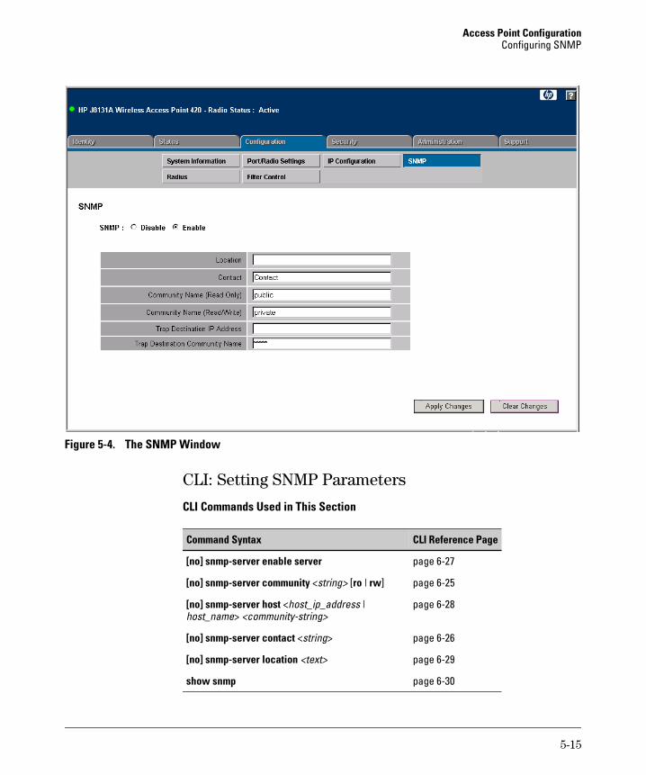
Access Point Configuration Configuring SNMP
Figure 5-4. The SNMP Window
CLI: Setting SNMP Parameters
CLI Commands Used in This Section
Command Syntax CLI Reference Page
[no] snmp-server enable server
[no] snmp-server community <string> [ro | rw]
[no] snmp-server host <host_ip_address | host_name> <community-string>
[no] snmp-server contact <string>
[no] snmp-server location <text>
show snmp
page 6-27
page 6-25
page 6-28
page 6-26
page 6-29
page 6-30
5-15
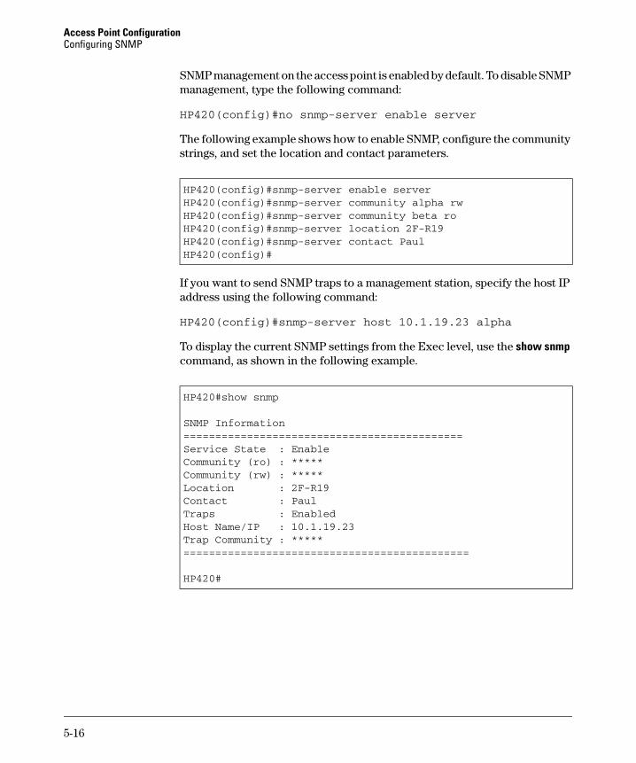
Access Point Configuration Configuring SNMP
SNMP management on the access point is enabled by default. To disable SNMP management, type the following command:
HP420(config)#no snmp-server enable server
The following example shows how to enable SNMP, configure the community strings, and set the location and contact parameters.
HP420(config)#snmp-server enable serverHP420(config)#snmp-server community alpha rwHP420(config)#snmp-server community beta roHP420(config)#snmp-server location 2F-R19HP420(config)#snmp-server contact PaulHP420(config)#
If you want to send SNMP traps to a management station, specify the host IP address using the following command:
HP420(config)#snmp-server host 10.1.19.23 alpha
To display the current SNMP settings from the Exec level, use the show snmp command, as shown in the following example.
HP420#show snmp
SNMP Information============================================Service State : EnableCommunity (ro) : *****Community (rw) : *****Location : 2F-R19Contact : PaulTraps : EnabledHost Name/IP : 10.1.19.23Trap Community : *****=============================================
HP420#
5-16
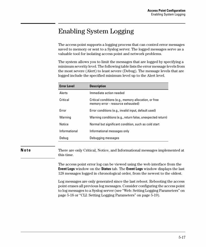
Access Point Configuration Enabling System Logging
Enabling System Logging
The access point supports a logging process that can control error messages saved to memory or sent to a Syslog server. The logged messages serve as a valuable tool for isolating access point and network problems.
The system allows you to limit the messages that are logged by specifying a minimum severity level. The following table lists the error message levels from the most severe (Alert) to least severe (Debug). The message levels that are logged include the specified minimum level up to the Alert level.
Error Level Description
Alerts Immediate action needed
Critical Critical conditions (e.g., memory allocation, or free memory error - resource exhausted)
Error Error conditions (e.g., invalid input, default used)
Warning Warning conditions (e.g., return false, unexpected return)
Notice Normal but significant condition, such as cold start
Informational Informational messages only
Debug Debugging messages
N o t e There are only Critical, Notice, and Informational messages implemented at this time.
The access point error log can be viewed using the web interface from the Event Logs window on the Status tab. The Event Logs window displays the last 128 messages logged in chronological order, from the newest to the oldest.
Log messages are only generated since the last reboot. Rebooting the access point erases all previous log messages. Consider configuring the access point to log messages to a Syslog server (see “Web: Setting Logging Parameters” on page 5-18 or “CLI: Setting Logging Parameters” on page 5-19).
5-17
Access Point Configuration Enabling System Logging
Web: Setting Logging Parameters
The System Servers window on the Administration tab enables system logs and Syslog server details to be configured for the access point.
The web interface enables you to modify these parameters:
■ System Log Setup: Enables the logging of error messages.
■ Logging Host: Enables the sending of log messages to a Syslog server host.
■ Server Name/IP: The IP address or name of a Syslog server.
■ Logging Console: Enables the logging of error messages to the console.
■ Logging Level: Sets the minimum severity level for event logging
To Enable Logging:
1. Select the Administration tab.
2. Click the [System Servers] button.
3. For System Log Setup, select Enable.
4. For Logging Level, select the minimum severity level to be logged.
5. (Optional) If you want to send log messages to a Syslog server, perform these steps:
a. Set Logging Host to Enable.
b. In the Server Name/IP field, type the IP address or name of a Syslog server.
6. (Optional) If you want to send log messages to the console, set Logging Console to Enable.
7. Click the [Apply Changes] button.
5-18
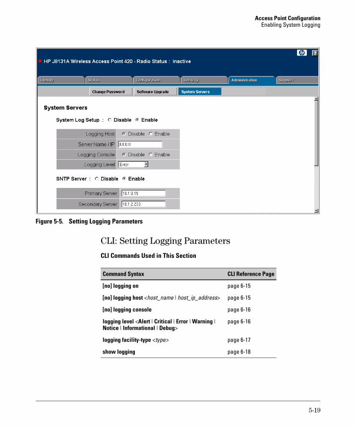
Access Point Configuration Enabling System Logging
Figure 5-5. Setting Logging Parameters
CLI: Setting Logging Parameters
CLI Commands Used in This Section
Command Syntax CLI Reference Page
[no] logging on page 6-15
[no] logging host <host_name | host_ip_address> page 6-15
[no] logging console page 6-16
logging level <Alert | Critical | Error | Warning | page 6-16 Notice | Informational | Debug>
logging facility-type <type> page 6-17
show logging page 6-18
5-19

Access Point Configuration Enabling System Logging
The following example shows how to enable logging, set the minimum severity level of messages to be logged, and send messages to the console.
HP420(config)#logging onHP420(config)#logging level criticalHP420(config)#logging consoleHP420(config)#
The following example shows how to configure the access point to send logging messages to a Syslog server. The CLI also provides a command to specify the facility type tag sent in Syslog messages. (See RFC 3164.) This type has no effect on the kind of messages reported by the access point. However, it may be used by the Syslog server to sort messages or to store messages in the corresponding database.
HP420(config)#logging host 10.1.0.3HP420(config)#logging facility-type 19HP420(config)#
To display the current logging settings from the Exec level, use the show logging command, as shown in the following example.
HP420#show logging
Logging Information============================================Syslog State : EnabledLogging Host State : EnabledLogging Console State : EnabledServer Domain name/IP : 10.1.0.3Logging Level : ErrorLogging Facility Type : 19=============================================
HP420#
5-20
Access Point Configuration Configuring SNTP
Configuring SNTP
Simple Network Time Protocol (SNTP) allows the access point to set its internal clock based on periodic updates from a time server (SNTP or NTP). Maintaining an accurate time on the access point enables the system log to record meaningful dates and times for event entries. If the clock is not set, the access point will only record the time from the factory default set at the last bootup.
The access point acts as an SNTP client in unicast mode, periodically sending time synchronization requests to specific time servers. You can configure up to two time server IP addresses. The access point will attempt to poll each server in the configured sequence.
SNTP is enabled by default. The access point also allows you to disable SNTP and set the system clock manually using the CLI.
Setting the Time Zone. SNTP uses Coordinated Universal Time (or UTC, formerly Greenwich Mean Time, or GMT) based on the time at the Earth’s prime meridian, zero degrees longitude. To display a time corresponding to your local time, you must indicate the number of hours and minutes your time zone is east or west of UTC.
Web: Setting SNTP Parameters
The System Servers window on the Administration tab enables SNTP server and time zone details to be configured for the access point.
The web interface enables you to modify these parameters:
■ SNTP Server: Configures the access point to operate as an SNTP unicast client. When enabled, at least one time server IP address must be specified.
• Primary Server: The IP address of an SNTP or NTP time server that the access point attempts to poll for a time update.
• Secondary Server: The IP address of a secondary SNTP or NTP time server. The access point first attempts to update the time from the primary server, if this fails it attempts an update from the secondary server.
■ Set Time Zone: Selects the time zone that specifies the number of hours before (east) or after (west) UTC.
5-21
Access Point Configuration Configuring SNTP
■ Enable Daylight Saving: The access point provides a way to automatically adjust the system clock for Daylight Saving Time (DST) changes. To use this feature you define the month and date to begin and to end the change from standard time. During this period the system clock is set back by one hour.
To Set SNTP Parameters:
1. Select the Administration tab.
2. Click the [System Servers] button.
3. For SNTP Server, select Enable.
4. For the primary time server, type the IP address in the Primary Server field.
5. For the secondary time server, type the IP address in the Secondary Server field.
6. From the Enter Time Zone drop-down menu, select the time appropriate for your region.
7. (Optional) If your region uses Daylight Saving Time, check the Enable Daylight Saving check box and then select the dates to implement this feature.
8. Click the [Apply Changes] button.
5-22
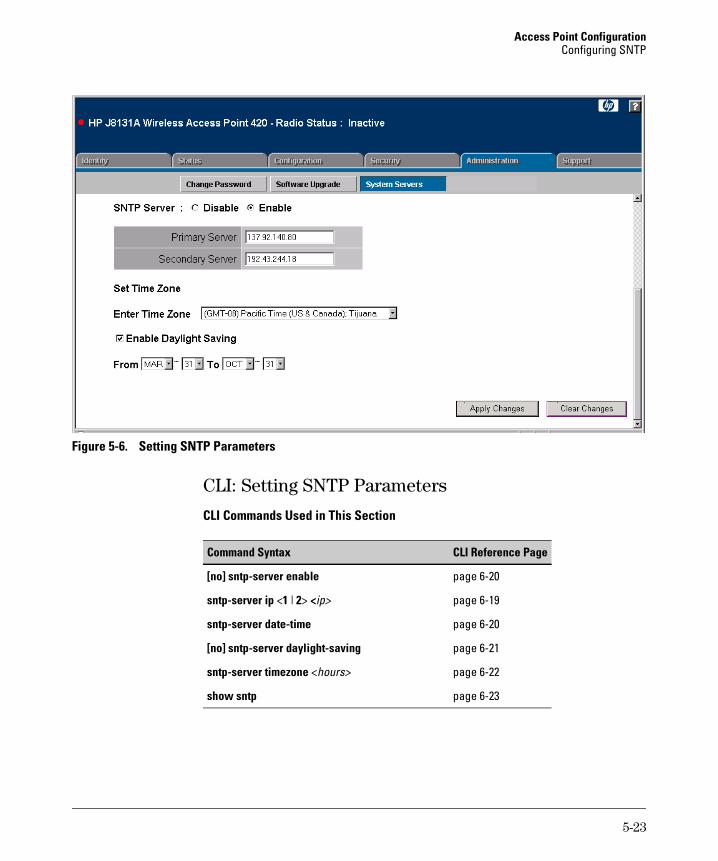
Access Point Configuration Configuring SNTP
Figure 5-6. Setting SNTP Parameters
CLI: Setting SNTP Parameters
CLI Commands Used in This Section
Command Syntax CLI Reference Page
[no] sntp-server enable�
sntp-server ip <1 | 2> <ip>
sntp-server date-time�
[no] sntp-server daylight-saving�
sntp-server timezone <hours>
show sntp�
page 6-20
page 6-19
page 6-20
page 6-21
page 6-22
page 6-23
5-23
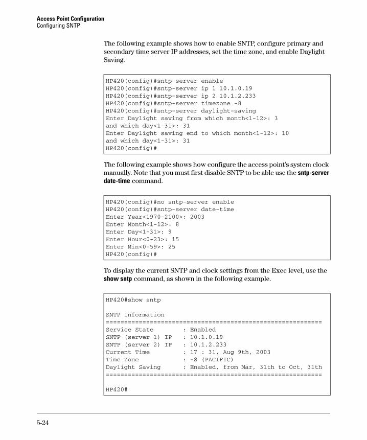
Access Point Configuration Configuring SNTP
The following example shows how to enable SNTP, configure primary and secondary time server IP addresses, set the time zone, and enable Daylight Saving.
HP420(config)#sntp-server enableHP420(config)#sntp-server ip 1 10.1.0.19HP420(config)#sntp-server ip 2 10.1.2.233HP420(config)#sntp-server timezone -8HP420(config)#sntp-server daylight-savingEnter Daylight saving from which month<1-12>: 3and which day<1-31>: 31Enter Daylight saving end to which month<1-12>: 10and which day<1-31>: 31HP420(config)#
The following example shows how configure the access point’s system clock manually. Note that you must first disable SNTP to be able use the sntp-server date-time command.
HP420(config)#no sntp-server enableHP420(config)#sntp-server date-timeEnter Year<1970-2100>: 2003Enter Month<1-12>: 8Enter Day<1-31>: 9Enter Hour<0-23>: 15Enter Min<0-59>: 25HP420(config)#
To display the current SNTP and clock settings from the Exec level, use the show sntp command, as shown in the following example.
HP420#show sntp
SNTP Information===========================================================Service State : EnabledSNTP (server 1) IP : 10.1.0.19SNTP (server 2) IP : 10.1.2.233Current Time : 17 : 31, Aug 9th, 2003Time Zone : -8 (PACIFIC)Daylight Saving : Enabled, from Mar, 31th to Oct, 31th===========================================================
HP420#
5-24
Access Point Configuration Configuring Ethernet Interface Parameters
Configuring Ethernet Interface Parameters
The access point’s Ethernet interface can be configured to use auto-negotiation to set the operating speed and duplex mode. When auto-negotiation is disabled, the operating speed and duplex mode must be manually set to match that of the connected device. Auto-negotiation is enabled by default.
N o t e When using auto-negotiation, be sure that the attached device supports IEEE 802.3u standard auto-negotiation and is not set to a forced speed and duplex mode.
Web: Setting Ethernet Interface Parameters
The Port/Radio Settings window on the Configuration tab enables the access point’s Ethernet interface settings to be configured.
The web interface enables you to modify these parameters:
■ Auto: The Ethernet interface automatically sets the operating speed and duplex mode to match that of the attached device.
■ 100Base-TX Full Duplex: The Ethernet interface is set to operate at 100 Mbps full duplex.
■ 100Base-TX Half Duplex: The Ethernet interface is set to operate at 100 Mbps half duplex.
■ 10Base-T Full Duplex: The Ethernet interface is set to operate at 10 Mbps full duplex.
■ 10Base-T Half Duplex: The Ethernet interface is set to operate at 10 Mbps half duplex.
To Configure Ethernet Interface Settings:
1. Select the Configuration tab.
2. Click the [Port/Radio Settings] button.
3. Under Port Settings, select the setting to match that of the connected device; either Auto or one of the forced speed and duplex mode options.
4. Click the [Apply Changes] button.
To display the current operating status for the Ethernet interface, use the AP Status window on the Status tab. See “The AP Status Window” on page 4-17.
5-25
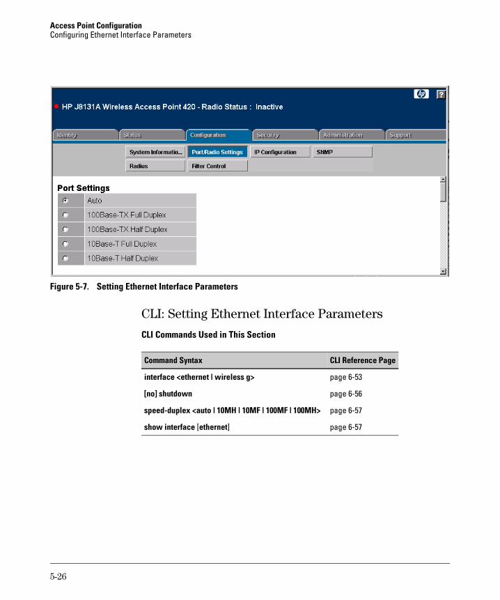
Access Point Configuration Configuring Ethernet Interface Parameters
Figure 5-7. Setting Ethernet Interface Parameters
CLI: Setting Ethernet Interface Parameters
CLI Commands Used in This Section
Command Syntax CLI Reference Page
interface <ethernet | wireless g> page 6-53
[no] shutdown page 6-56
speed-duplex <auto | 10MH | 10MF | 100MF | 100MH> page 6-57
show interface [ethernet] page 6-57
5-26
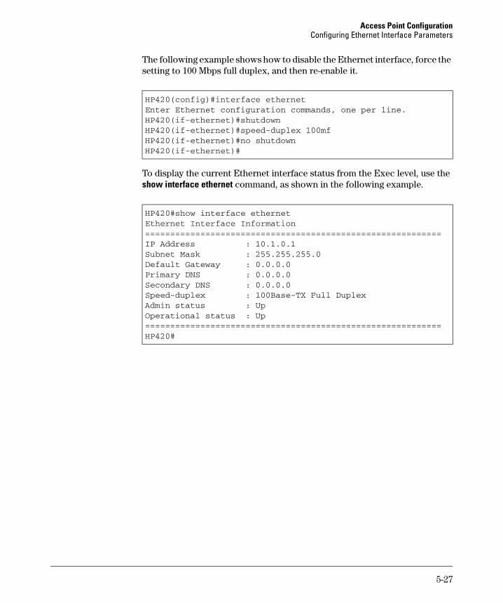
Access Point Configuration Configuring Ethernet Interface Parameters
The following example shows how to disable the Ethernet interface, force the setting to 100 Mbps full duplex, and then re-enable it.
HP420(config)#interface ethernetEnter Ethernet configuration commands, one per line.HP420(if-ethernet)#shutdownHP420(if-ethernet)#speed-duplex 100mfHP420(if-ethernet)#no shutdownHP420(if-ethernet)#
To display the current Ethernet interface status from the Exec level, use the show interface ethernet command, as shown in the following example.
HP420#show interface ethernetEthernet Interface Information===========================================================IP Address : 10.1.0.1Subnet Mask : 255.255.255.0Default Gateway : 0.0.0.0Primary DNS : 0.0.0.0Secondary DNS : 0.0.0.0Speed-duplex : 100Base-TX Full DuplexAdmin status : UpOperational status : Up===========================================================HP420#
5-27
Access Point Configuration Configuring RADIUS Client Authentication
Configuring RADIUS Client Authentication
Remote Authentication Dial-in User Service (RADIUS) is an authentication protocol that uses software running on a central server to control access to RADIUS-aware devices on the network. An authentication server contains a database of user credentials for each user that requires access to the network.
A primary RADIUS server must be specified for the access point to implement IEEE 802.1x network access control and Wi-Fi Protected Access (WPA) wireless security. A secondary RADIUS server may also be specified as a backup should the primary server fail or become inaccessible.
N o t e This configuration guide assumes that you have already configured the RADIUS server(s) to support the access point. The configuration of RADIUS server software is beyond the scope of this guide, refer to the documentation provided with the RADIUS server software.
Web: Setting RADIUS Server Parameters
The Radius window on the Configuration tab provides the primary and secondary RADIUS server setup parameters.
The web interface enables you to modify these parameters to use RADIUS authentication on the access point:
■ Primary Radius Server Setup: Configure the following settings to use RADIUS authentication on the access point.
• IP Address: Specifies the IP address or host name of the RADIUS server.
• Port: The User Datagram Protocol (UDP) port number used by the RADIUS server for authentication messages. (Range: 1024-65535; Default: 1812)
• Secret Key: A shared text string used to encrypt messages between the access point and the RADIUS server. Be sure that the same text string is specified on the RADIUS server. Do not use blank spaces in the string. (Maximum length: 20 characters)
• Timeout: Number of seconds the access point waits for a reply from the RADIUS server before resending a request. The default is 5 seconds. (Range: 1-60 seconds)
5-28

Access Point Configuration Configuring RADIUS Client Authentication
• Retransmit Attempts: The number of times the access point tries to resend a request to the RADIUS server before authentication fails. (Range: 1 - 30)
■ Secondary Radius Server Setup: Configure a secondary RADIUS server to provide a backup in case the primary server fails. The access point uses the secondary server if the primary server fails or becomes inaccessible. Once the access point switches over to the secondary server, it periodically attempts to establish communication again with primary server. If communication with the primary server is re-established, the secondary server reverts to a backup role.
To Set RADIUS Server Parameters:
1. Select the Configuration tab.
2. Click the [Radius] button.
3. For the primary RADIUS server, type the IP address in the IP Address field.
4. In the Port field, specify the UDP port number used by the RADIUS server for authentication. The default and recommended port number is 1812.
5. In the Secret Key field, specify the shared text string that is also used by the RADIUS server.
6. (Optional) For the Timeout and Retransmit Attempts fields, accept the default values unless you experience problems connecting to the RADIUS server over the network.
7. (Optional) If you have a secondary RADIUS server in the network, specify its IP address and other parameters in the appropriate fields. Otherwise, leave the IP address setting as all zeros (0.0.0.0).
8. Click the [Apply Changes] button.
5-29
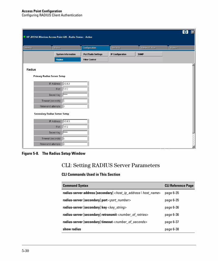
Access Point Configuration Configuring RADIUS Client Authentication
Figure 5-8. The Radius Setup Window
CLI: Setting RADIUS Server Parameters
CLI Commands Used in This Section
Command Syntax CLI Reference Page
radius-server address [secondary] <host_ip_address | host_name> page 6-35
radius-server [secondary] port <port_number> page 6-35
radius-server [secondary] key <key_string> page 6-36
radius-server [secondary] retransmit <number_of_retries> page 6-36
radius-server [secondary] timeout <number_of_seconds> page 6-37
show radius page 6-38
5-30
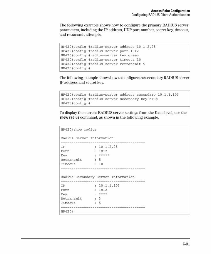
Access Point Configuration Configuring RADIUS Client Authentication
The following example shows how to configure the primary RADIUS server parameters, including the IP address, UDP port number, secret key, timeout, and retransmit attempts.
HP420(config)#radius-server address 10.1.2.25HP420(config)#radius-server port 1812HP420(config)#radius-server key greenHP420(config)#radius-server timeout 10HP420(config)#radius-server retransmit 5HP420(config)#
The following example shows how to configure the secondary RADIUS server IP address and secret key.
HP420(config)#radius-server address secondary 10.1.1.103HP420(config)#radius-server secondary key blueHP420(config)#
To display the current RADIUS server settings from the Exec level, use the show radius command, as shown in the following example.
HP420#show radius
Radius Server Information========================================IP : 10.1.2.25Port : 1812Key : *****Retransmit : 5Timeout : 10========================================
Radius Secondary Server Information========================================IP : 10.1.1.103Port : 1812Key : ****Retransmit : 3Timeout : 5========================================HP420#
5-31
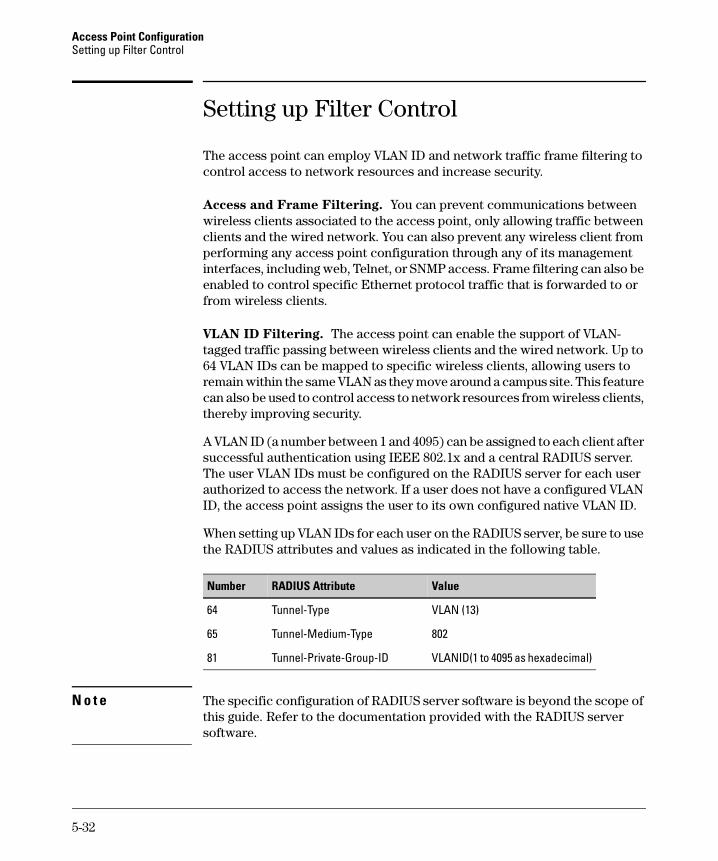
Access Point Configuration Setting up Filter Control
Setting up Filter Control
The access point can employ VLAN ID and network traffic frame filtering to control access to network resources and increase security.
Access and Frame Filtering. You can prevent communications between wireless clients associated to the access point, only allowing traffic between clients and the wired network. You can also prevent any wireless client from performing any access point configuration through any of its management interfaces, including web, Telnet, or SNMP access. Frame filtering can also be enabled to control specific Ethernet protocol traffic that is forwarded to or from wireless clients.
VLAN ID Filtering. The access point can enable the support of VLAN-tagged traffic passing between wireless clients and the wired network. Up to 64 VLAN IDs can be mapped to specific wireless clients, allowing users to remain within the same VLAN as they move around a campus site. This feature can also be used to control access to network resources from wireless clients, thereby improving security.
A VLAN ID (a number between 1 and 4095) can be assigned to each client after successful authentication using IEEE 802.1x and a central RADIUS server. The user VLAN IDs must be configured on the RADIUS server for each user authorized to access the network. If a user does not have a configured VLAN ID, the access point assigns the user to its own configured native VLAN ID.
When setting up VLAN IDs for each user on the RADIUS server, be sure to use the RADIUS attributes and values as indicated in the following table.
Number RADIUS Attribute Value
64 Tunnel-Type VLAN (13)
65 Tunnel-Medium-Type 802
81 Tunnel-Private-Group-ID VLANID(1 to 4095 as hexadecimal)
N o t e The specific configuration of RADIUS server software is beyond the scope of this guide. Refer to the documentation provided with the RADIUS server software.
5-32

Access Point Configuration Setting up Filter Control
When VLAN filtering is enabled, the access point must also have 802.1x authentication enabled (see page 5-57) and a RADIUS server configured (see page 5-28). Wireless clients must also support 802.1x client software to be assigned to a specific VLAN.
With VLANs enabled, the access point’s Ethernet interface drops all received traffic that does not include a VLAN tag. To maintain network connectivity to the access point and wireless clients, be sure that the access point is connected to a device port that supports IEEE 802.1Q VLAN tags.
When VLAN filtering is disabled, the access point ignores the VLAN tags on any received frames.
Web: Enabling VLAN Support and Setting Filters
The Filter Control window on the Configuration tab to configure frame filtering on the access point’s wireless and Ethernet interfaces.
The web interface enables you to modify these parameters:
■ Native VLAN ID: The VLAN ID assigned to wireless client users that are not assigned to a specific VLAN by RADIUS server configuration. The Native VLAN ID is limited to a number between 1 and 64.
■ VLAN: Enables or disables VLAN tagging support on the access point.
■ Local Bridge Filter: Controls wireless-to-wireless communications between clients through the access point. However, it does not affect communications between wireless clients and the wired network.
• Disable: Allows wireless-to-wireless communications between clients through the access point.
• Enable: Blocks wireless-to-wireless communications between clients through the access point.
■ AP Management Filter: Controls management access to the access point from wireless clients. Management interfaces include the web, Telnet, or SNMP.
• Disable: Allows management access from wireless clients.
• Enable: Blocks management access from wireless clients.
■ Ethernet Type Filter: Controls checks on the Ethernet type of all incoming and outgoing Ethernet packets against the protocol filtering table.
• Disable: Access point does not filter Ethernet protocol types.
• Enable: Access point filters Ethernet protocol types based on the configuration of protocol types in the filter table. If a protocol has its status set to “ON,” the protocol is not passed by the access point.
5-33
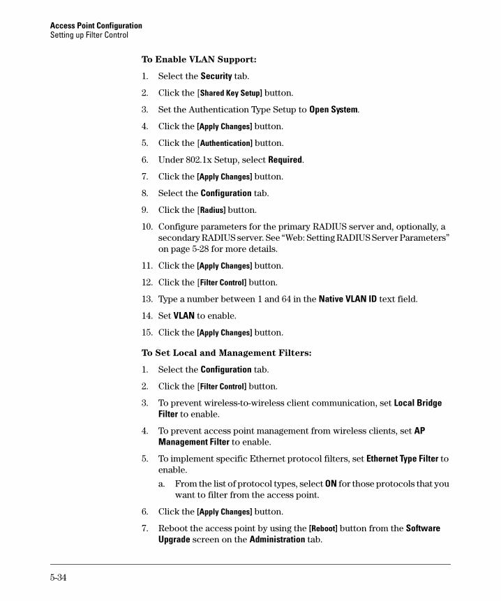
Access Point Configuration Setting up Filter Control
To Enable VLAN Support:
1. Select the Security tab.
2. Click the [Shared Key Setup] button.
3. Set the Authentication Type Setup to Open System.
4. Click the [Apply Changes] button.
5. Click the [Authentication] button.
6. Under 802.1x Setup, select Required.
7. Click the [Apply Changes] button.
8. Select the Configuration tab.
9. Click the [Radius] button.
10. Configure parameters for the primary RADIUS server and, optionally, a secondary RADIUS server. See “Web: Setting RADIUS Server Parameters” on page 5-28 for more details.
11. Click the [Apply Changes] button.
12. Click the [Filter Control] button.
13. Type a number between 1 and 64 in the Native VLAN ID text field.
14. Set VLAN to enable.
15. Click the [Apply Changes] button.
To Set Local and Management Filters:
1. Select the Configuration tab.
2. Click the [Filter Control] button.
3. To prevent wireless-to-wireless client communication, set Local Bridge �Filter to enable.
4. To prevent access point management from wireless clients, set AP�Management Filter to enable.
5. To implement specific Ethernet protocol filters, set Ethernet Type Filter toenable.
a. From the list of protocol types, select ON for those protocols that you want to filter from the access point.
6. Click the [Apply Changes] button.
7. Reboot the access point by using the [Reboot] button from the Software �Upgrade screen on the Administration tab.
5-34
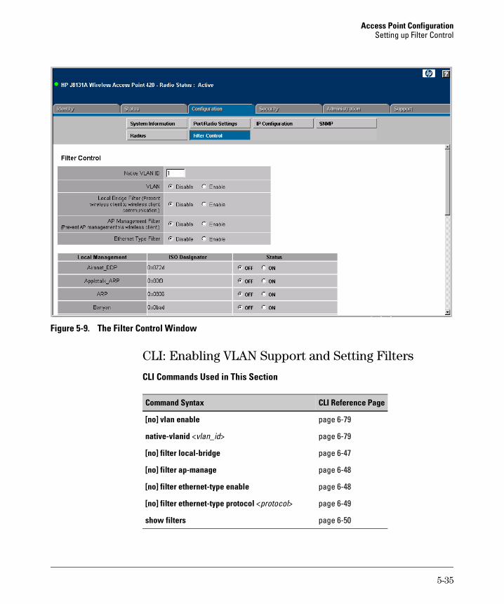
Access Point Configuration Setting up Filter Control
Figure 5-9. The Filter Control Window
CLI: Enabling VLAN Support and Setting Filters
CLI Commands Used in This Section
Command Syntax CLI Reference Page
[no] vlan enable�
native-vlanid <vlan_id>
[no] filter local-bridge�
[no] filter ap-manage�
[no] filter ethernet-type enable�
[no] filter ethernet-type protocol <protocol>
show filters�
page 6-79
page 6-79
page 6-47
page 6-48
page 6-48
page 6-49
page 6-50
5-35
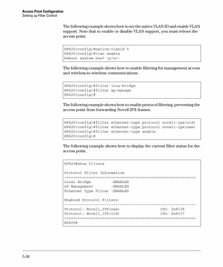
Access Point Configuration Setting up Filter Control
-----------------------------------------------------------
The following example shows how to set the native VLAN ID and enable VLAN support. Note that to enable or disable VLAN support, you must reboot the access point.
HP420(config)#native-vlanid 5HP420(config)#vlan enableReboot system now? <y/n>:
The following example shows how to enable filtering for management access and wireless-to-wireless communications.
HP420(config)#filter loca-bridgeHP420(config)#filter ap-manageHP420(config)#
The following example shows how to enable protocol filtering, preventing the access point from forwarding Novell IPX frames.
HP420(config)#filter ethernet-type protocol novell-ipx(old)HP420(config)#filter ethernet-type protocol novell-ipx(new)HP420(config)#filter ethernet-type enableHP420(config)#
The following example shows how to display the current filter status for the access point.
HP420#show filters
Protocol Filter Information===========================================================Local Bridge :ENABLEDAP Management :ENABLEDEthernet Type Filter :ENABLED
Enabled Protocol Filters
Protocol: Novell_IPX(new) ISO: 0x8138Protocol: Novell_IPX(old) ISO: 0x8137===========================================================HP420#
5-36
Access Point Configuration Modifying Radio Settings
Modifying Radio Settings
The access point can operate in three standard modes, IEEE 802.11b only, 802.11g only, or a mixed 802.11b/802.11g mode.
N o t e Both the IEEE 802.11g and 802.11b standards operate within the 2.4 GHz band. In a wireless LAN environment there can often be interference from other 2.4 GHz devices, such as cordless phones. If you experience poor wireless LAN performance, try to limit any possible sources of radio interference within the service area.
The IEEE 802.11g standard is an extension of the IEEE 802.11b standard and enables client stations with 802.11b wireless network cards to associate to an 802.11g access point. However, the 802.11b standard uses Complementary Code Keying (CCK) modulation technology to achieve a communication rate of up to 11 Mbps, whereas 802.11g uses Orthogonal Frequency Division Multiplexing (OFDM) to reach rates of up to 54 Mbps. (Note that the 802.11g standard is backward-compatible with 802.11b and therefore includes the ability to use OFDM or CCK modulation.) To support both 802.11g and 802.11b clients, the access point has to first communicate with all clients using CCK and only switch to OFDM for data transfers between 802.11g-compatible clients. This mechanism has the effect of reducing the maximum throughput for 802.11g clients in the network.
Working in its mixed “b/g” mode, the access point will experience reduced data throughput, even if there are no 802.11b clients active in the network. To achieve a higher throughput, you can set the access point to operate in 802.11g-only mode, which ignores all 802.11b clients in the service area.
N o t e Both the IEEE 802.11g and 802.11b standards operate within the 2.4 GHz band. If you are operating in “802.11g-only” mode, any 802.11b devices in the service area will contribute to the radio frequency noise and affect network performance.
Web: Modifying the Radio Working Mode and Settings
The Port/Radio Settings window on the Configuration tab provides the basic settings for the access point’s radio operation.
The access point’s radio channel settings are limited by local regulations, which determine the number of channels that are available.
5-37
Access Point Configuration Modifying Radio Settings
N o t e If you are using the worldwide product, J8131A, before you can configure the radio settings the Country Setting must be set using the CLI. See “Using the CLI to Set the Country Code” on page 5-41.
The web interface enables you to modify these parameters:
■ Working Mode: Selects a standard operating mode for the access point.
• b & g mixed mode: Both 802.11b and 802.11g clients can communicate with the access point. This is the default configuration.
• g only mode: Only 802.11g clients can communicate with the access point.
• b only mode: Both 802.11b and 802.11g clients can communicate with the access point, but 802.11g clients can only transfer data at 802.11b standard rates (up to 11 Mbps).
■ Radio: Enables radio communications on the access point.
■ Radio Channel: The radio channel that the access point uses to communicate with wireless clients. When multiple access points are deployed in the same area, be sure to choose a channel separated by at least five channels to avoid having the channels interfere with each other. You can deploy up to three access points in the same area (for example, channels 1, 6, 11).
■ Auto Channel Select: Enables the access point to automatically select an unoccupied radio channel.
■ Transmit Power: Adjusts the power of the radio signals transmitted from the access point. The higher the transmission power, the farther the transmission range.
■ Maximum Station Data Rate: The maximum data rate at which a client can connect to the access point. The maximum transmission distance is affected by the data rate. The lower the data rate, the longer the transmission distance.
■ Beacon Interval: The rate at which beacon signals are transmitted from the access point. The beacon signals allow wireless clients to maintain contact with the access point. They may also carry power-management information.
■ Data Beacon Rate: The rate at which stations in sleep mode must wake up to receive broadcast/multicast transmissions.
Known also as the Delivery Traffic Indication Map (DTIM) interval, it indicates how often the MAC layer forwards broadcast/multicast traffic, which is necessary to wake up stations that are using Power Save mode. The default value of 2 indicates that the access point will save all broad-cast/multicast frames for the Basic Service Set (BSS) and forward them
5-38
Access Point Configuration Modifying Radio Settings
after every second beacon. Using smaller DTIM intervals delivers broad-cast/multicast frames in a more timely manner, causing stations in Power Save mode to wake up more often and drain power faster. Using higher DTIM values reduces the power used by stations in Power Save mode, but delays the transmission of broadcast/multicast frames.
■ RTS Threshold: Sets the packet size threshold at which a Request to Send (RTS) signal must be sent to a receiving station prior to the sending station starting communications. The access point sends RTS frames to a receiving station to negotiate the sending of a data frame. After receiving an RTS frame, the station sends a CTS (clear to send) frame to notify the sending station that it can start sending data.
If the RTS threshold is set to 0, the access point never sends RTS signals. If set to 2347, the access point always sends RTS signals. If set to any other value, and the packet size equals or exceeds the RTS threshold, the RTS/ CTS (Request to Send / Clear to Send) mechanism will be enabled.
To Change the Working Mode:
1. Select the Configuration tab.
2. Click the [Port/Radio Settings] button.
3. Select the working mode you want to use, b & g mixed mode, g only mode, or b only mode.
4. Click the [Radio Mode Change] button.
To Modify Radio Settings:
1. Select the Configuration tab.
2. Click the [Port/Radio Settings] button.
3. To enable the radio, check the Enable check box next to Radio.
4. Select Enable for Auto Channel Select, or select a specific number for the Radio Channel. If you are deploying access points in the same area, be sure to select channel numbers that are at least five apart (for example, channels 1, 6, 11).
5. Modify other radio parameters, if appropriate.
6. Click the [Apply Changes] button.
5-39
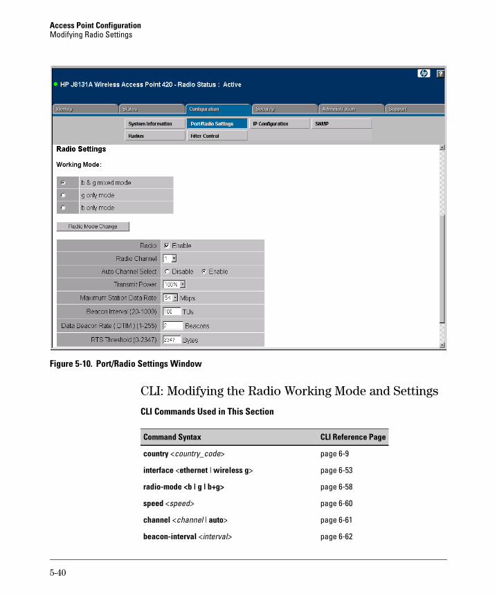
Access Point Configuration Modifying Radio Settings
Figure 5-10. Port/Radio Settings Window
CLI: Modifying the Radio Working Mode and Settings
CLI Commands Used in This Section
Command Syntax CLI Reference Page
country <country_code>
interface <ethernet | wireless g>
radio-mode <b | g | b+g>�
speed <speed>
channel <channel | auto>
beacon-interval <interval>
page 6-9
page 6-53
page 6-58
page 6-60
page 6-61
page 6-62
5-40
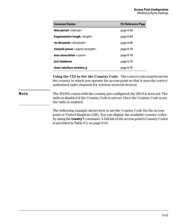
Access Point Configuration Modifying Radio Settings
Command Syntax CLI Reference Page
dtim-period <interval>
fragmentation-length <length>
rts-threshold <threshold>
transmit-power <signal-strength>
max-association <count>
[no] shutdown�
show interface wireless g�
page 6-63
page 6-64
page 6-65
page 6-70
page 6-70
page 6-75
page 6-75
Using the CLI to Set the Country Code. The correct code must be set for the country in which you operate the access point so that it uses the correct authorized radio channels for wireless network devices.
N o t e The J8130A comes with the country pre-configured; the J8131A does not. The radio is disabled if the Country Code is not set. Once the Country Code is set, the radio is enabled.
The following example shows how to set the Country Code for the access point to United Kingdom (GB). You can display the available country codes by using the country ? command. A full list of the access point’s Country Codes is provided in Table 6-1 on page 6-10.
5-41

Access Point Configuration Modifying Radio Settings
HP420#country ?WORD Country code: AL-ALBANIA, DZ-ALGERIA, AR-ARGENTINA, AM-ARMENIA,
AU-AUSTRALIA, AT-AUSTRIA, AZ-AZERBAIJAN, BH-BAHRAIN, BY-BELARUS,BE-BELGIUM, BZ-BELIZE, BO-BOLVIA, BR-BRAZIL, BN-BRUNEI_DARUSSALAM,BG-BULGARIA, CA-CANADA, CL-CHILE, CN-CHINA, CO-COLOMBIA, CR-COSTA_RICA,HR-CROATIA, CY-CYPRUS, CZ-CZECH_REPUBLIC, DK-DENMARK,DO-DOMINICAN_REPUBLIC, EC-ECUADOR, EG-EGYPT, EE-ESTONIA, FI-FINLAND,FR-FRANCE, GE-GEORGIA, DE-GERMANY, GR-GREECE, GT-GUATEMALA,HK-HONG_KONG, HU-HUNGARY, IS-ICELAND, IN-INDIA, ID-INDONESIA, IR-IRAN,IE-IRELAND, IL-ISRAEL, IT-ITALY, JP-JAPAN, JO-JORDAN, KZ-KAZAKHSTAN,KP-NORTH KOREA, KR-KOREA_REPUBLIC, KW-KUWAIT, LV-LATVIA, LB-LEBANON,LI-LIECHTENSTEIN, LT-LITHUANIA, LU-LUXEMBOURG, MO-MACAU, MK-MACEDONIA,MY-MALAYSIA, MX-MEXICO, MC-MONACO, MA-MOROCCO, NA-NORTH_AMERICA,NL-NETHERLANDS, NZ-NEW_ZEALAND, NO-NORWAY, OM-OMAN, PK-PAKISTAN,PA-PANAMA, PE-PERU, PH-PHILIPPINES, PL-POLAND, PT-PORTUGAL,PR-PUERTO_RICO, QA-QATAR, RO-ROMANIA, RU-RUSSIA, SA-SAUDI_ARABIA,SG-SINGAPORE, SK-SLOVAK_REPUBLIC, SI-SLOVENIA, ZA-SOUTH_AFRICA,ES-SPAIN, SE-SWEDEN, CH-SWITZERLAND, SY-SYRIA, TW-TAIWAN, TH-THAILAND,TR-TURKEY, UA-UKRAINE, AE-UNITED_ARAB_EMIRATES, GB-UNITED_KINGDOM,US-UNITED_STATES, UY-URUGUAY, VE-VENEZUELA, VN-VIETNAM
HP420#country gbHP420#
Once the Country Code has been set, the CLI command is no longer available. If you need to change the Country Code, you must reload the access point default configuration by using the reset configuration command, or by pressing the access point’s Reset button for more than five seconds.
Using the CLI to Set the Working Mode. The following example shows how to set the working mode for the access point to 802.11g-only mode.
HP420(config)#interface wireless gEnter Wireless configuration commands, one per line.HP420(if-wireless g)#radio-mode gHP420(if-wireless g)#
N o t e You must set the Country Code and radio mode before configuring other radio settings. These basic settings affect the radio channels and values that are available for other parameters.
5-42
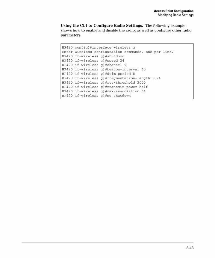
Access Point Configuration Modifying Radio Settings
Using the CLI to Configure Radio Settings. The following example shows how to enable and disable the radio, as well as configure other radio parameters.
HP420(config)#interface wireless gEnter Wireless configuration commands, one per line.HP420(if-wireless g)#shutdownHP420(if-wireless g)#speed 24HP420(if-wireless g)#channel 9HP420(if-wireless g)#beacon-interval 60HP420(if-wireless g)#dtim-period 8HP420(if-wireless g)#fragmentation-length 1024HP420(if-wireless g)#rts-threshold 2000HP420(if-wireless g)#transmit-power halfHP420(if-wireless g)#max-association 64HP420(if-wireless g)#no shutdown
5-43

Access Point Configuration Modifying Radio Settings
To display the current radio settings from the Exec level, use the show interface wireless g command, as shown in the following example.
HP420#show interface wireless g
Wireless Interface Information===========================================================----------------Identification-----------------------------Description : Enterprise 802.11g Access PointSSID : Enterprise Wireless APRadio mode : 802.11b onlyChannel : 9Status : Enabled----------------802.11 Parameters--------------------------Transmit Power : HALF (18 dBm)Max Station Data Rate : 24MbpsFragmentation Threshold : 1024 bytesRTS Threshold : 2000 bytesBeacon Interval : 60 TUsDTIM Interval : 8 beaconsMaximum Association : 64 stations----------------Security-----------------------------------Closed System : DISABLEDWPA mode : Dynamic keyMulticast cipher : WEPUnicast cipher : TKIPWPA clients : SUPPORTEDAuthentication Type : OPENEncryption : DISABLEDDefault Transmit Key : 1WEP Key Data Type : HexadecimalStatic Keys :Key 1: EMPTY Key 2: EMPTY Key 3: EMPTY Key 4: EMPTY
===========================================================HP420#
5-44
Access Point Configuration Configuring Wireless Security
Configuring Wireless Security
The access point is configured by default as an “open system,” which broad-casts a beacon signal including the configured SSID. Wireless clients can read the SSID from the beacon, and automatically reset their SSID to allow immediate connection to the nearest access point.
To improve wireless network security, you have to implement two main functions:
■ Authentication: It must be verified that clients attempting to connect to the network are authorized users.
■ Traffic Encryption: Data passing between the access point and clients must be protected from interception and eves dropping.
For a more secure network, the access point can implement one or a combination of the following security mechanisms:
■ Wired Equivalent Privacy (WEP)
■ IEEE 802.1x
■ Wireless MAC address filtering
■ Wi-Fi Protected Access (WPA)
The security mechanisms that may be employed depend on the level of security required, the network and management resources available, and the software support provided on wireless clients.
Wired Equivalent Privacy (WEP) . WEP provides a basic level of security, preventing unauthorized access to the network and encrypting data transmitted between wireless clients and the access point. WEP uses static shared keys (fixed-length hexadecimal or alphanumeric strings) that are manually distributed to all clients that want to use the network.
WEP is the security protocol initially specified in the IEEE 802.11 standard for wireless communications. Unfortunately, WEP has been found to be seriously flawed and cannot be recommended for a high level of network security. For more robust wireless security, the access point provides Wi-Fi Protected Access (WPA) for improved data encryption and user authentication.
IEEE 802.1x Network Access Control. IEEE 802.1x is a standard frame-work for network access control that uses a central RADIUS server for user authentication. This control feature prevents unauthorized access to the
5-45
Access Point Configuration Configuring Wireless Security
network by requiring an 802.1x client application to submit user credentials for authentication. The 802.1x standard uses the Extensible Authentication Protocol (EAP) to pass user credentials (either digital certificates, usernames and passwords, or other) from the client to the RADIUS server. Client authentication is then verified on the RADIUS server before the access point grants client access to the network.
The 802.1x EAP packets are also used to pass dynamic unicast session keys and static broadcast keys to wireless clients. Session keys are unique to each client and are used to encrypt and correlate traffic passing between a specific client and the access point. You can also enable broadcast key rotation, so the access point provides a dynamic broadcast key and changes it at a specified interval.
MAC Address Filtering. Using MAC address filtering, you can configure the access point with a list of the MAC addresses of wireless clients that are authorized to access the network. This provides a basic level of authentication for wireless clients attempting to gain access to the network. A database of authorized MAC addresses can be stored locally on the access point or remotely on a central RADIUS server.
Wi-Fi Protected Access (WPA). WPA employs a combination of several technologies to provide an enhanced security solution for 802.11 wireless networks. The access point supports the following WPA components and features:
■ IEEE 802.1x (802.1x) and the Extensible Authentication Protocol
(EAP): WPA employs 802.1x as its basic framework for user authentication and dynamic key management. The 802.1x client and RADIUS server should use an appropriate EAP type—such as EAP-TLS (Transport Layer Security), EAP-TTLS (Tunneled TLS), or PEAP (Protected EAP)—for strongest authentication. Working together, these protocols provide “mutual authentication” between a client, the access point, and a RADIUS server that prevents users from accidentally joining a rogue network. Only when a RADIUS server has authenticated a user’s credentials will encryption keys be sent to the access point and client.
N o t e Implementing WPA on wireless clients requires a WPA-enabled network card driver and 802.1x client software that supports the EAP authentication type that you want to use. Windows XP provides native WPA support, other systems require additional software.
■ Temporal Key Integrity Protocol (TKIP): WPA specifies TKIP as the data encryption method to replace WEP. TKIP avoids the problems of WEP static keys by dynamically changing data encryption keys. Basically,
5-46
Access Point Configuration Configuring Wireless Security
TKIP starts with a master (temporal) key for each user session and then mathematically generates other keys to encrypt each data packet. TKIP provides further data encryption enhancements by including a message integrity check for each packet and a re-keying mechanism, which periodically changes the master key.
■ WPA Pre-Shared Key (PSK) Mode: For enterprise deployment, WPA requires a RADIUS authentication server to be configured on the wired network. However, for small office networks that may not have the resources to configure and maintain a RADIUS server, WPA provides a simple operating mode that uses just a pre-shared password for network access. The Pre-Shared Key mode uses a common password for user authentication that is manually entered on the access point and all wireless clients. The PSK mode uses the same TKIP packet encryption and key management as WPA in the enterprise, so it provides a robust and manage-able alternative for small networks.
■ Mixed WPA and WEP Client Support: WPA enables the access point to indicate its supported encryption and authentication mechanisms to clients using its beacon signal. WPA-compatible clients can likewise respond to indicate their WPA support. This enables the access point to determine which clients are using WPA security and which are using legacy WEP. The access point uses TKIP unicast data encryption keys for WPA clients and WEP unicast keys for WEP clients. The global encryption key for multicast and broadcast traffic must be the same for all clients, therefore it restricts encryption to a WEP key.
■ Advanced Encryption Standard (AES) Support: WPA specifies AES encryption as an optional alternative to TKIP and WEP. AES provides very strong encryption using a completely different ciphering algorithm to TKIP and WEP. The developing IEEE 802.11i wireless security standard has specified AES as an eventual replacement for TKIP and WEP. However, because of the difference in ciphering algorithms, AES requires new hardware support in client network cards that is currently not widely available. The access point includes AES support as a future security enhancement.
5-47
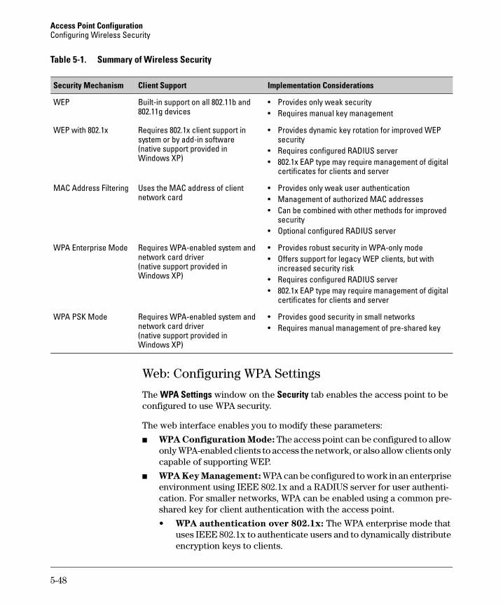
Access Point Configuration Configuring Wireless Security
Table 5-1. Summary of Wireless Security
Security Mechanism Client Support Implementation Considerations
WEP Built-in support on all 802.11b and 802.11g devices
WEP with 802.1x Requires 802.1x client support in system or by add-in software (native support provided in Windows XP)
MAC Address Filtering Uses the MAC address of client network card
WPA Enterprise Mode Requires WPA-enabled system and network card driver (native support provided in Windows XP)
WPA PSK Mode Requires WPA-enabled system and network card driver (native support provided in Windows XP)
• Provides only weak security • Requires manual key management
• Provides dynamic key rotation for improved WEP security
• Requires configured RADIUS server • 802.1x EAP type may require management of digital
certificates for clients and server
• Provides only weak user authentication • Management of authorized MAC addresses • Can be combined with other methods for improved
security • Optional configured RADIUS server
• Provides robust security in WPA-only mode • Offers support for legacy WEP clients, but with
increased security risk • Requires configured RADIUS server • 802.1x EAP type may require management of digital
certificates for clients and server
• Provides good security in small networks • Requires manual management of pre-shared key
Web: Configuring WPA Settings
The WPA Settings window on the Security tab enables the access point to be configured to use WPA security.
The web interface enables you to modify these parameters:
■ WPA Configuration Mode: The access point can be configured to allow only WPA-enabled clients to access the network, or also allow clients only capable of supporting WEP.
■ WPA Key Management: WPA can be configured to work in an enterprise environment using IEEE 802.1x and a RADIUS server for user authentication. For smaller networks, WPA can be enabled using a common pre-shared key for client authentication with the access point.
• WPA authentication over 802.1x: The WPA enterprise mode that uses IEEE 802.1x to authenticate users and to dynamically distribute encryption keys to clients.
5-48
Access Point Configuration Configuring Wireless Security
• WPA Pre-shared Key: The WPA mode for small networks that uses a common password string that is manually distributed. If this mode is selected, be sure to also specify the key string.
■ Multicast Cipher Mode: Selects an encryption method for the global key used for multicast and broadcast traffic, which is supported by all wireless clients.
• WEP: WEP is the first generation security protocol used to encrypt data crossing the wireless medium using a fairly short key. Communicating devices must use the same WEP key to encrypt and decrypt radio signals. WEP has many security flaws, and is not recommended for transmitting highly-sensitive data.
• TKIP: TKIP provides data encryption enhancements including per-packet key hashing (that is, changing the encryption key on each packet), a message integrity check, an extended initialization vector with sequencing rules, and a re-keying mechanism.
• AES: AES has been designated by the National Institute of Standards and Technology as the successor to the Data Encryption Standard (DES) encryption algorithm, and will be used by the U.S. government for encrypting all sensitive, nonclassified information. Because of its strength, and resistance to attack, AES is also being incorporated as part of the 802.11 standard.
■ WPA Pre-Shared Key Type: If the WPA pre-shared-key mode is used, all wireless clients must be configured with the same key to communicate with the access point.
• Hexadecimal: Enter a key as a string of 64 hexadecimal numbers.
• Alphanumeric: Enter a key as an easy-to-remember form of letters and numbers. The string must be from 8 to 63 characters, which can include spaces.
To Configure WPA in Enterprise Mode:
1. Select the Configuration tab.
2. Click the [Radius] button.
3. Configure parameters for the primary RADIUS server and, optionally, a secondary RADIUS server. See “Web: Setting RADIUS Server Parameters” on page 5-28 for more details.
4. Click the [Apply Changes] button.
5. Select the Security tab.
6. Click the [Shared Key Setup] button.
7. Set the Authentication Type Setup to Open System.
5-49
Access Point Configuration Configuring Wireless Security
8. Click the [Apply Changes] button.
9. Click the [Authentication] button.
10. Under 802.1x Setup, select Required.
11. If there are clients in the service area that are not WPA-enabled, enter timeperiods for refreshing the session and broadcast encryption keys, and forre-authenticating the client.
12. Click the [Apply Changes] button.
13. Click the [WPA Settings] button.
14. Under WPA Configuration Mode, check Required if you want only WPA-enabled clients to connect to the network. If you want some clients toconnect that are not WPA-enabled, leave this check box clear.
15. Under Multicast Cipher Mode, select WEP if you are supporting any clients that are not WPA-enabled, otherwise select TKIP. Only select AES if youare sure that all clients support AES encryption.
16. Click the [Apply Changes] button.
To Configure WPA in Pre-shared Key Mode:
1. Select the Security tab.
2. Click the [Shared Key Setup] button.
3. Set the Authentication Type Setup to Open System.
4. Click the [Apply Changes] button.
5. Click the [Authentication] button.
6. Under 802.1x Setup, select Disable.
7. Click the [Apply Changes] button.
8. Click the [WPA Settings] button.
9. Under WPA Configuration Mode, check Required.
10. Under WPA Pre-Shared Key Type, select Hexadecimal or Alphanumeric.
11. For the WPA Pre-Shared Key, enter exactly 64 hexadecimal digits orbetween 8 and 63 alphanumeric characters. (Be sure that all wireless clients use the same pre-shared key.)
12. Click the [Apply Changes] button.
5-50
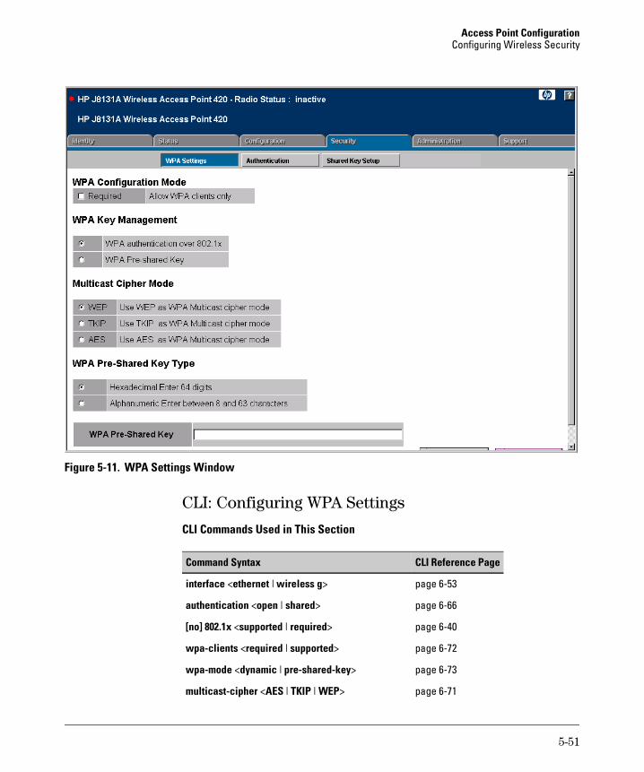
Access Point Configuration Configuring Wireless Security
Figure 5-11. WPA Settings Window
CLI: Configuring WPA Settings
CLI Commands Used in This Section
Command Syntax CLI Reference Page
interface <ethernet | wireless g>
authentication <open | shared>
[no] 802.1x <supported | required>
wpa-clients <required | supported>
wpa-mode <dynamic | pre-shared-key>
multicast-cipher <AES | TKIP | WEP>
page 6-53
page 6-66
page 6-40
page 6-72
page 6-73
page 6-71
5-51
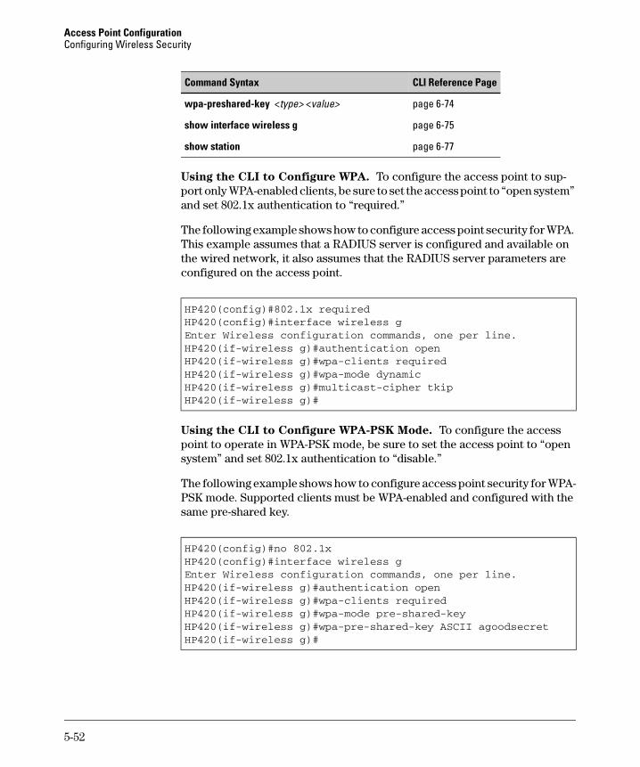
Access Point Configuration Configuring Wireless Security
Command Syntax CLI Reference Page
wpa-preshared-key <type> <value> page 6-74
show interface wireless g page 6-75
show station page 6-77
Using the CLI to Configure WPA. To configure the access point to sup-port only WPA-enabled clients, be sure to set the access point to “open system” and set 802.1x authentication to “required.”
The following example shows how to configure access point security for WPA. This example assumes that a RADIUS server is configured and available on the wired network, it also assumes that the RADIUS server parameters are configured on the access point.
HP420(config)#802.1x requiredHP420(config)#interface wireless gEnter Wireless configuration commands, one per line.HP420(if-wireless g)#authentication openHP420(if-wireless g)#wpa-clients requiredHP420(if-wireless g)#wpa-mode dynamicHP420(if-wireless g)#multicast-cipher tkipHP420(if-wireless g)#
Using the CLI to Configure WPA-PSK Mode. To configure the access point to operate in WPA-PSK mode, be sure to set the access point to “open system” and set 802.1x authentication to “disable.”
The following example shows how to configure access point security for WPAPSK mode. Supported clients must be WPA-enabled and configured with the same pre-shared key.
HP420(config)#no 802.1xHP420(config)#interface wireless gEnter Wireless configuration commands, one per line.HP420(if-wireless g)#authentication openHP420(if-wireless g)#wpa-clients requiredHP420(if-wireless g)#wpa-mode pre-shared-keyHP420(if-wireless g)#wpa-pre-shared-key ASCII agoodsecretHP420(if-wireless g)#
5-52
Access Point Configuration Configuring Wireless Security
Web: Configuring MAC Address Authentication
The access point can be configured to authenticate client MAC addresses against a database stored locally on the access point or remotely on a RADIUS server. Client MAC addresses in the local database can be specified as allowed or denied access the network. This enables the access point to control which devices can associate with the access point.
N o t e If a RADIUS authentication server is used for MAC authentication, the server must first be configured in the RADIUS window.
Client station MAC authentication occurs prior to any IEEE 802.1x authentication configured for the access point. However, a client’s MAC address provides relatively weak user authentication, since MAC addresses can be easily captured and used by another station to break into the network. Using 802.1x provides more robust user authentication using user names and pass-words or digital certificates. So, although you can configure the access point to use MAC address and 802.1x authentication together, it is better to choose one or the other, as appropriate. Consider the following guidelines:
■ Use MAC address authentication for a small network with a limited number of users. MAC addresses can be manually configured on the access point itself without the need to set up a RADIUS server. The access point supports up to 1024 MAC addresses in its filtering table, but managing a large number of MAC addresses across more than one access point quickly becomes very cumbersome.
■ Use IEEE 802.1x authentication for networks with a larger number of users and where security is the most important issue. A RADIUS server is required in the wired network to control the user credentials (digital certificates, smart cards, passwords, or other) of wireless clients. The 802.1x authentication approach provides a standards-based, flexible, and scalable solution that can be centrally managed. However, implementing 802.1x requires more resources and skills to operate and maintain a RADIUS server and manage a large database of user credentials.
The Authentication window on the Security tab enables the access point to be configured to use MAC address authentication.
The web interface enables you to modify these parameters:
■ MAC Authentication: The type of authentication method the system employs when authenticating a wireless client’s MAC address.
5-53
Access Point Configuration Configuring Wireless Security
• Local MAC: The MAC address of the associating station is compared against the local database stored on the access point. The Local MAC Authentication section enables the local database to be set up. The access point supports up to 1024 MAC addresses.
• Radius MAC: The MAC address of the associating station is sent to a configured RADIUS server for authentication.
• Disable: No checks are performed on an associating station’s MAC address.
■ Local MAC Authentication: Configures the local MAC authentication database. The MAC database provides a mechanism to take certain actions based on a wireless client’s MAC address. The MAC list can be configured to allow or deny network access to specific clients.
• System Default: Specifies a default action for all unknown MAC addresses (that is, those not listed in the local MAC database). – Deny: Blocks access for all MAC addresses except those listed
in the local database as “allowed.” – Allow: Permits access for all MAC addresses except those listed
in the local database as “denied.”
■ MAC Authentication Settings: Enters specified MAC addresses and permissions into the local MAC database.
• MAC Address: Physical address of a client. Enter six pairs of hexadecimal digits separated by hyphens, for example, 00-90-D1-12-AB-89.
• Permission: Select Allow to permit access or Deny to block access. If Delete is selected, the specified MAC address entry is removed from the database.
• Update: Enters the specified MAC address and permission setting into the local database.
■ MAC Authentication Table: Displays current entries in the local MAC database.
To Configure MAC Authentication Using a Local Database:
1. Select the Security tab.
2. Click the [Authentication] button.
3. Set MAC Authentication to Local MAC.
4. Under Local MAC authentication, set System Default to Deny. This blocks all unknown MAC addresses from gaining access to the network.
5. Click the [Apply Changes] button.
6. Under MAC Authentication Settings, enter an authorized client MAC address in the MAC address text field.
5-54
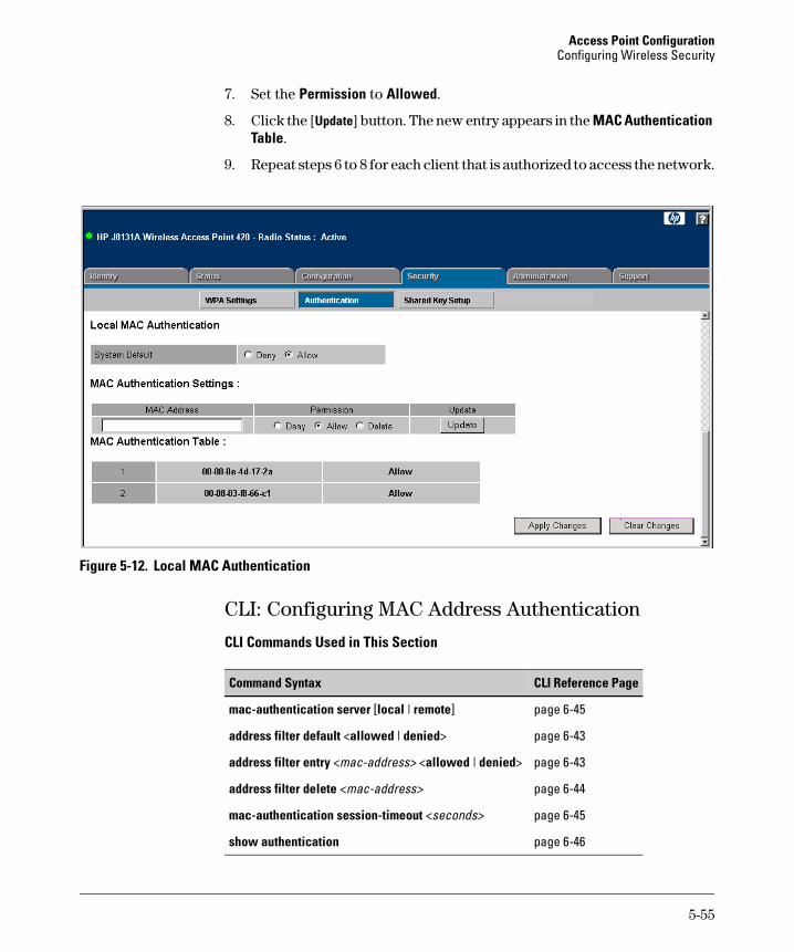
Access Point Configuration Configuring Wireless Security
7. Set the Permission to Allowed.
8. Click the [Update] button. The new entry appears in the MAC Authentication Table.
9. Repeat steps 6 to 8 for each client that is authorized to access the network.
Figure 5-12. Local MAC Authentication
CLI: Configuring MAC Address Authentication
CLI Commands Used in This Section
Command Syntax CLI Reference Page
mac-authentication server [local | remote] page 6-45
address filter default <allowed | denied> page 6-43
address filter entry <mac-address> <allowed | denied> page 6-43
address filter delete <mac-address> page 6-44
mac-authentication session-timeout <seconds> page 6-45
show authentication page 6-46
5-55
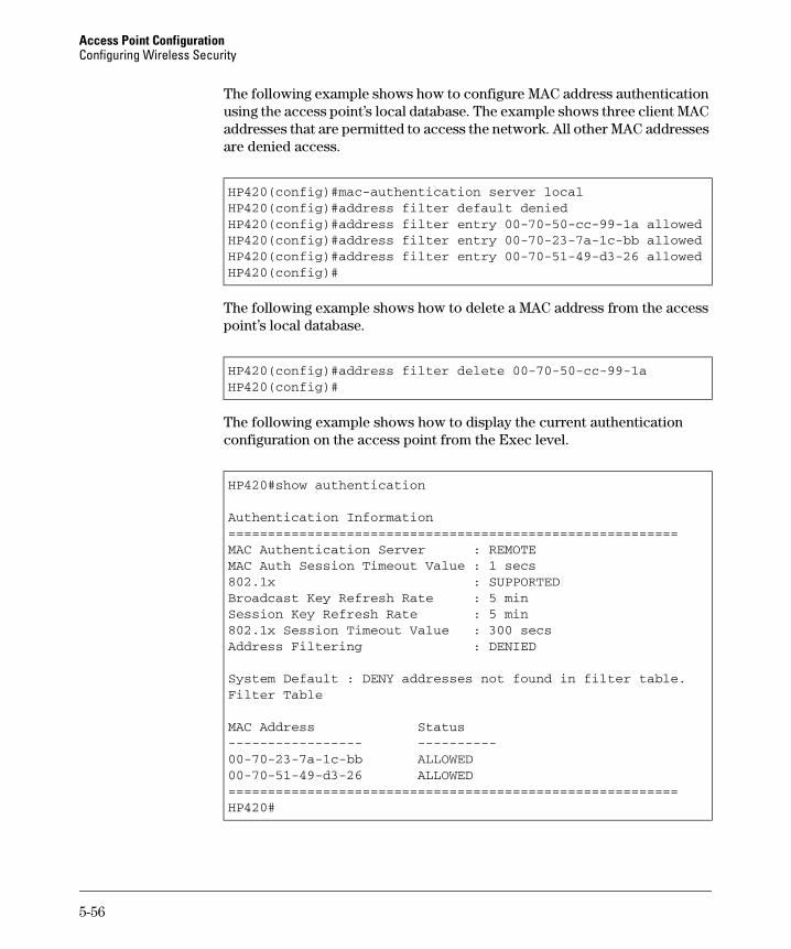
Access Point Configuration Configuring Wireless Security
-----------------
The following example shows how to configure MAC address authentication using the access point’s local database. The example shows three client MAC addresses that are permitted to access the network. All other MAC addresses are denied access.
HP420(config)#mac-authentication server localHP420(config)#address filter default deniedHP420(config)#address filter entry 00-70-50-cc-99-1a allowedHP420(config)#address filter entry 00-70-23-7a-1c-bb allowedHP420(config)#address filter entry 00-70-51-49-d3-26 allowedHP420(config)#
The following example shows how to delete a MAC address from the access point’s local database.
HP420(config)#address filter delete 00-70-50-cc-99-1aHP420(config)#
The following example shows how to display the current authentication configuration on the access point from the Exec level.
HP420#show authentication
Authentication Information=========================================================MAC Authentication Server : REMOTEMAC Auth Session Timeout Value : 1 secs802.1x : SUPPORTEDBroadcast Key Refresh Rate : 5 minSession Key Refresh Rate : 5 min802.1x Session Timeout Value : 300 secsAddress Filtering : DENIED
System Default : DENY addresses not found in filter table.Filter Table
MAC Address Status----------
00-70-23-7a-1c-bb ALLOWED00-70-51-49-d3-26 ALLOWED=========================================================HP420#
5-56
Access Point Configuration Configuring Wireless Security
Web: Configuring IEEE 802.1x
The access point supports IEEE 802.1x (802.1x) access control for wireless clients. This control feature prevents unauthorized access to the network by requiring an 802.1x client application to submit user credentials for authentication. Client authentication is then verified by a RADIUS server using Extensible Authentication Protocol (EAP) before the access point grants a client access to the network.
N o t e The 802.1x access control feature requires a RADIUS authentication server to be configured and available in the wired network. Be sure that the server’s details are configured in the RADIUS window.
The access point also uses the 802.1x Extensible Authentication Protocol Over LANs (EAPOL) packets to pass dynamic unicast session keys and static broadcast keys to wireless clients. Session keys are unique to each client and are used to authenticate a client connection, and correlate traffic passing between a specific client and the access point. You can also enable broadcast key rotation, so the access point provides a dynamic broadcast key and changes it at a specified interval.
The Authentication window on the Security tab enables 802.1x to be configured for the access point.
The web interface enables you to modify these parameters:
802.1x Setup. You can enable 802.1x as optionally supported or as required to enhance the security of the wireless network. When 802.1x is enabled, the broadcast and session key rotation intervals can also be configured.
■ Disable: The access point does not support 802.1x authentication for any wireless client. After successful wireless association with the access point, each client is allowed to access the network.
■ Supported: The access point supports 802.1x authentication only for clients initiating the 802.1x authentication process (the access point does not initiate 802.1x authentication). For clients initiating 802.1x, only those successfully authenticated are allowed to access the network. For those clients not initiating 802.1x, access to the network is allowed after successful wireless association with the access point.
■ Required: The access point enforces 802.1x authentication for all associated wireless clients. If 802.1x authentication is not initiated by a client, the access point will initiate authentication. Only those clients success-fully authenticated with 802.1x are allowed to access the network.
5-57
Access Point Configuration Configuring Wireless Security
■ Broadcast Key Refresh Rate: Sets the interval at which the broadcast keys are refreshed for stations using 802.1x dynamic keying. (Range: 0 -1440 minutes; Default: 0 = disabled)
■ Session Key Refresh Rate: The interval at which the access point refreshes unicast session keys for associated clients. (Range: 0 - 1440 minutes; Default: 0 = disabled)
■ 802.1x Reauthentication Refresh Rate: The time period after which a connected client must be re-authenticated. During the re-authentication process of verifying the client credentials on the RADIUS server, the client remains connected the network. Only if re-authentication fails is network access blocked. (Range: 0-65535 seconds; Default: 0 = Disabled)
To Configure 802.1x Authentication and Key Management:
1. Select the Configuration tab.
2. Click the [Radius] button.
3. Configure parameters for the primary RADIUS server and, optionally, a secondary RADIUS server. See “Web: Setting RADIUS Server Parameters” on page 5-28 for more details.
4. Click the [Apply Changes] button.
5. Select the Security tab.
6. Click the [Shared Key Setup] button.
7. Set the Authentication Type Setup to Open System.
8. Click the [Apply Changes] button.
9. Click the [Authentication] button.
10. Under 802.1x Setup, select Required.
11. For the Broadcast Key Refresh Rate, enter a time period between 0 (disabled) and 1440 minutes.
12. For the Session Key Refresh Rate, enter a time period between 0 (disabled) and 1440 minutes.
13. For the 802.1x Re-Authentication Refresh Rate, enter a time period between 0 (disabled) and 65535 seconds.
14. Click the [Apply Changes] button.
5-58
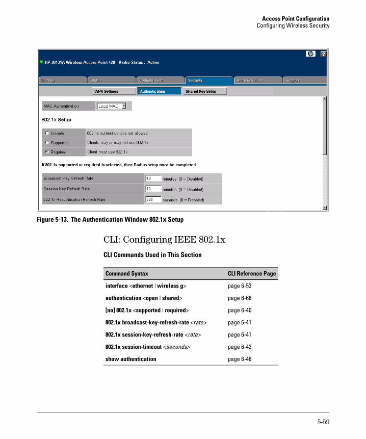
Access Point Configuration Configuring Wireless Security
Figure 5-13. The Authentication Window 802.1x Setup
CLI: Configuring IEEE 802.1x
CLI Commands Used in This Section
Command Syntax CLI Reference Page
interface <ethernet | wireless g>
authentication <open | shared>
[no] 802.1x <supported | required>
802.1x broadcast-key-refresh-rate <rate>
802.1x session-key-refresh-rate <rate>
802.1x session-timeout <seconds>
show authentication�
page 6-53
page 6-66
page 6-40
page 6-41
page 6-41
page 6-42
page 6-46
5-59
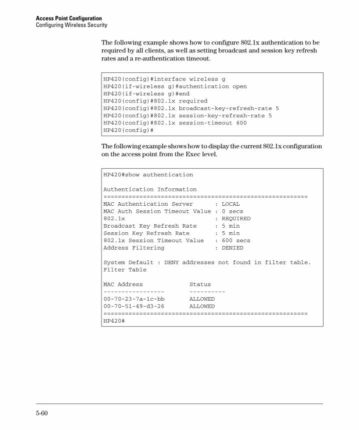
Access Point Configuration Configuring Wireless Security
-----------------
The following example shows how to configure 802.1x authentication to be required by all clients, as well as setting broadcast and session key refresh rates and a re-authentication timeout.
HP420(config)#interface wireless gHP420(if-wireless g)#authentication openHP420(if-wireless g)#endHP420(config)#802.1x requiredHP420(config)#802.1x broadcast-key-refresh-rate 5HP420(config)#802.1x session-key-refresh-rate 5HP420(config)#802.1x session-timeout 600HP420(config)#
The following example shows how to display the current 802.1x configuration on the access point from the Exec level.
HP420#show authentication
Authentication Information=========================================================MAC Authentication Server : LOCALMAC Auth Session Timeout Value : 0 secs802.1x : REQUIREDBroadcast Key Refresh Rate : 5 minSession Key Refresh Rate : 5 min802.1x Session Timeout Value : 600 secsAddress Filtering : DENIED
System Default : DENY addresses not found in filter table.Filter Table
MAC Address Status----------
00-70-23-7a-1c-bb ALLOWED00-70-51-49-d3-26 ALLOWED=========================================================HP420#
5-60
Access Point Configuration Configuring Wireless Security
Web: Setting up WEP Shared-Keys
Setting up shared keys enables the basic IEEE 802.11 Wired Equivalent Privacy (WEP) on the access point to prevent unauthorized access to the network.
If you choose to use WEP shared keys instead of an open system, be sure to define at least one static WEP key for user authentication and data encryption. Also, be sure that the WEP shared keys are the same for each client in the wireless network.
N o t e WEP has been found to be seriously flawed and cannot be recommended for a high level of network security. For more robust wireless security, the access point provides Wi-Fi Protected Access (WPA) for improved data encryption and user authentication.
The Shared Key Setup window on the Security tab enables WEP shared keys to be configured for the access point.
The web interface enables you to modify these parameters:
■ Authentication Type Setup: Sets the access point to communicate with clients using pre-configured static shared keys or as an open system that accepts network access attempts from any client.
• Open System: Select this option if you plan to use WPA or 802.1x as a security mechanism. If you don’t set up any other security mechanism on the access point, the network has no protection and is open to all users.
• Shared Key: Sets the access point to use WEP shared keys. If this option is selected, you must configure at least one key on the access point and all clients.
■ Wired Equivalent Privacy (WEP) Setup: Enable or disable the access point to use WEP shared keys. If this option is selected, you must configure at least one key on the access point and all clients.
■ Shared Key Setup: Select 64 Bit, 128 Bit, or 152 Bit. Note that the same size of encryption key must be supported on all wireless clients.
■ Key Type: Select the preferred method of entering WEP encryption keys on the access point and enter up to four keys:
• Hexadecimal: Enter keys as 10 hexadecimal digits (0 to 9 and A to F) for 64 bit keys, 26 hexadecimal digits for 128 bit keys, or 32 hexadecimal digits for 152 bit keys.
5-61

Access Point Configuration Configuring Wireless Security
• Alphanumeric: Enter keys as 5 alphanumeric characters for 64 bit keys, 13 alphanumeric characters for 128 bit keys, or 16 alphanumeric characters for 152 bit keys.
■ Transmit Key Select: Selects the key number to use for encryption.
To Configure WEP Shared Keys:
1. Select the Security tab.
2. Click the [Shared Key Setup] button.
3. Set the Authentication Type Setup to Shared Key.
4. Set Wired Equivalent Privacy (WEP) Setup to Enabled.
5. Select the size of the encryption key to be used by all clients, 64 bit, 128 bit, or 152 bit.
6. Select the method to enter the keys, Hexadecimal or Alphanumeric.
7. Enter one or more keys in the table conforming the method and size already selected.
8. Select one of the entered keys as the Transmit Key to be used to encrypt data transmitted from the access point. Other keys can be shared with clients and used for decryption.
9. Click the [Apply Changes] button.
5-62
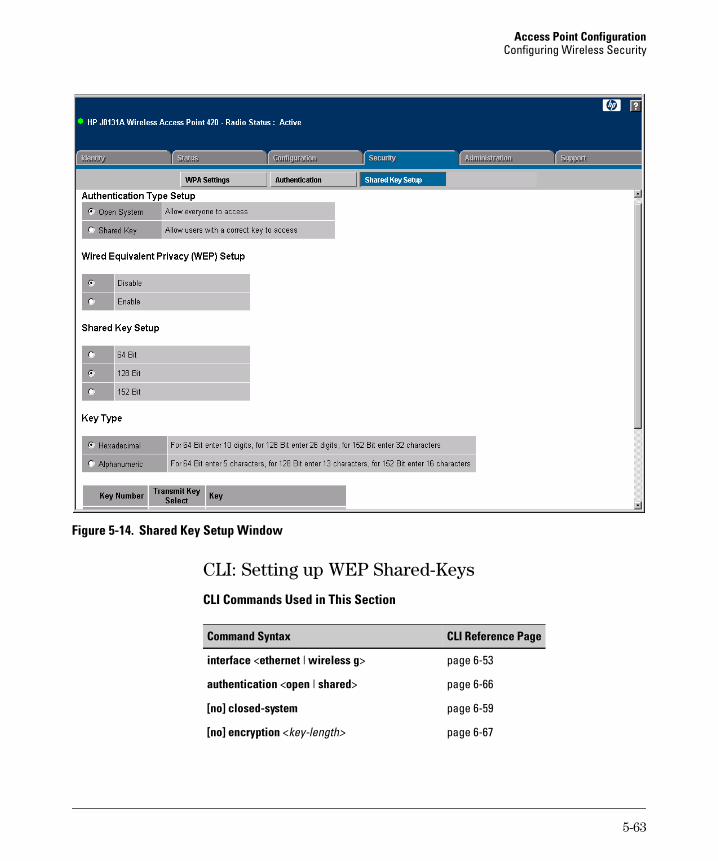
Access Point Configuration Configuring Wireless Security
Figure 5-14. Shared Key Setup Window
CLI: Setting up WEP Shared-Keys
CLI Commands Used in This Section
Command Syntax CLI Reference Page
interface <ethernet | wireless g> page 6-53
authentication <open | shared> page 6-66
[no] closed-system page 6-59
[no] encryption <key-length> page 6-67
5-63
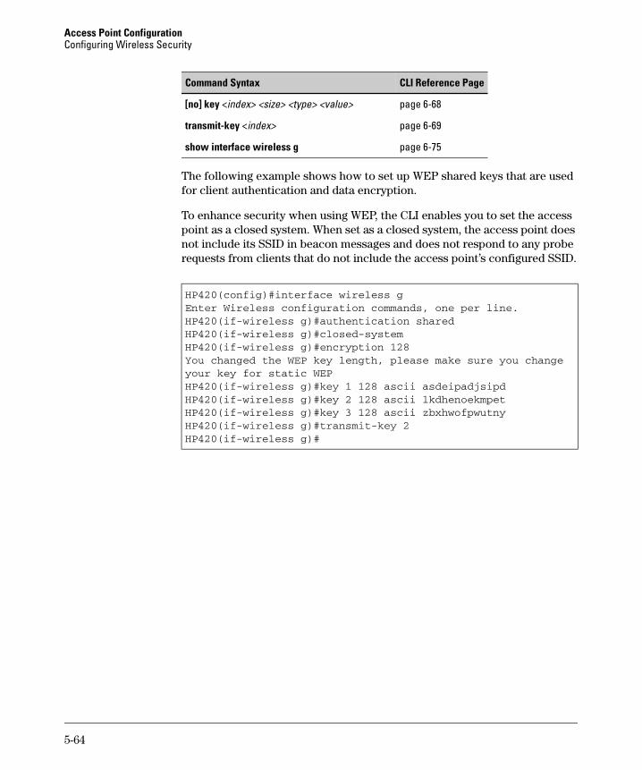
Access Point Configuration Configuring Wireless Security
Command Syntax CLI Reference Page
[no] key <index> <size> <type> <value> page 6-68
transmit-key <index> page 6-69
show interface wireless g page 6-75
The following example shows how to set up WEP shared keys that are used for client authentication and data encryption.
To enhance security when using WEP, the CLI enables you to set the access point as a closed system. When set as a closed system, the access point does not include its SSID in beacon messages and does not respond to any probe requests from clients that do not include the access point’s configured SSID.
HP420(config)#interface wireless gEnter Wireless configuration commands, one per line.HP420(if-wireless g)#authentication sharedHP420(if-wireless g)#closed-systemHP420(if-wireless g)#encryption 128You changed the WEP key length, please make sure you change your key for static WEPHP420(if-wireless g)#key 1 128 ascii asdeipadjsipdHP420(if-wireless g)#key 2 128 ascii lkdhenoekmpetHP420(if-wireless g)#key 3 128 ascii zbxhwofpwutnyHP420(if-wireless g)#transmit-key 2HP420(if-wireless g)#
5-64
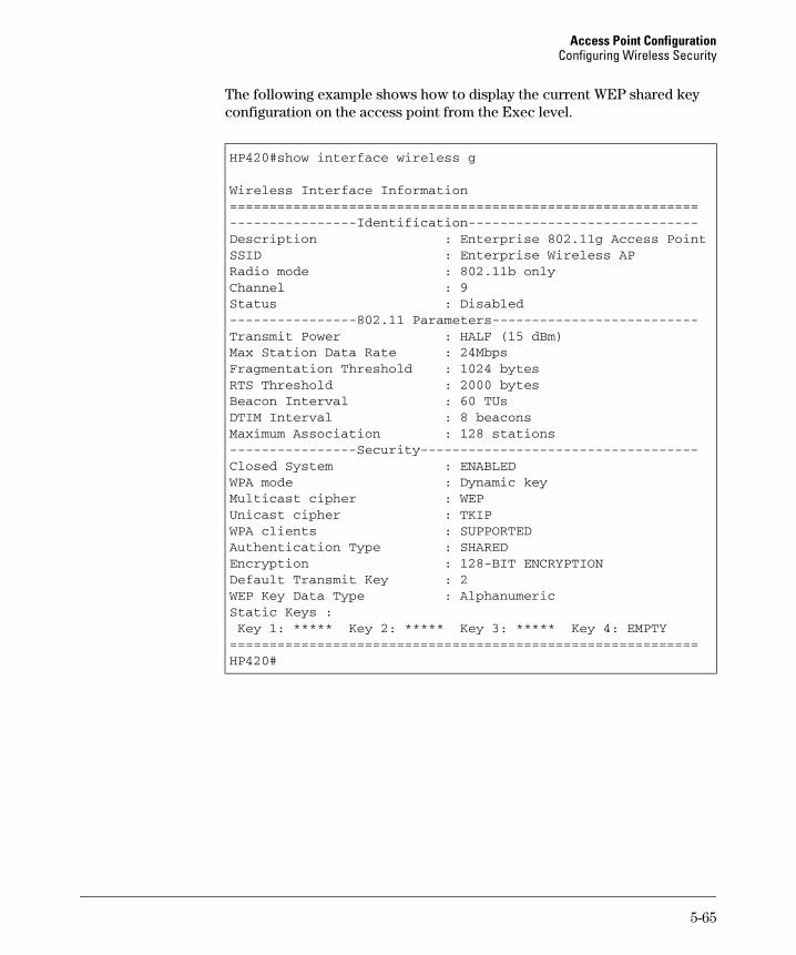
Access Point Configuration Configuring Wireless Security
The following example shows how to display the current WEP shared key configuration on the access point from the Exec level.
HP420#show interface wireless g
Wireless Interface Information===========================================================----------------Identification-----------------------------Description : Enterprise 802.11g Access PointSSID : Enterprise Wireless APRadio mode : 802.11b onlyChannel : 9Status : Disabled----------------802.11 Parameters--------------------------Transmit Power : HALF (15 dBm)Max Station Data Rate : 24MbpsFragmentation Threshold : 1024 bytesRTS Threshold : 2000 bytesBeacon Interval : 60 TUsDTIM Interval : 8 beaconsMaximum Association : 128 stations----------------Security-----------------------------------Closed System : ENABLEDWPA mode : Dynamic keyMulticast cipher : WEPUnicast cipher : TKIPWPA clients : SUPPORTEDAuthentication Type : SHAREDEncryption : 128-BIT ENCRYPTIONDefault Transmit Key : 2WEP Key Data Type : AlphanumericStatic Keys :Key 1: ***** Key 2: ***** Key 3: ***** Key 4: EMPTY
===========================================================HP420#
5-65

Access Point Configuration Configuring Wireless Security
5-66
6
Command Line Reference
Contents
Overview . . . . . . . . . . . . . . . . . . . . . . . . . . . . . . . . . . . . . . . . . . . . . . . . . . . . . 6-2
General Commands . . . . . . . . . . . . . . . . . . . . . . . . . . . . . . . . . . . . . . . . . . . . 6-3
System Management Commands . . . . . . . . . . . . . . . . . . . . . . . . . . . . . . . 6-8
SNMP Commands . . . . . . . . . . . . . . . . . . . . . . . . . . . . . . . . . . . . . . . . . . . . 6-25
Flash/File Commands . . . . . . . . . . . . . . . . . . . . . . . . . . . . . . . . . . . . . . . . . 6-30
RADIUS Client . . . . . . . . . . . . . . . . . . . . . . . . . . . . . . . . . . . . . . . . . . . . . . . 6-34
802.1x Port Authentication . . . . . . . . . . . . . . . . . . . . . . . . . . . . . . . . . . . 6-39
Filtering Commands . . . . . . . . . . . . . . . . . . . . . . . . . . . . . . . . . . . . . . . . . . 6-47
Interface Commands . . . . . . . . . . . . . . . . . . . . . . . . . . . . . . . . . . . . . . . . . 6-51
IAPP Command . . . . . . . . . . . . . . . . . . . . . . . . . . . . . . . . . . . . . . . . . . . . . . 6-77
VLAN Commands . . . . . . . . . . . . . . . . . . . . . . . . . . . . . . . . . . . . . . . . . . . . . 6-78
6-1
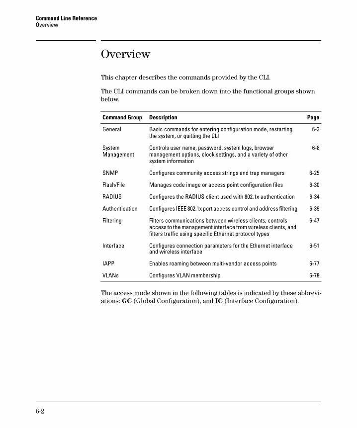
Command Line Reference Overview
Overview
This chapter describes the commands provided by the CLI.
The CLI commands can be broken down into the functional groups shown below.
Command Group Description Page
General Basic commands for entering configuration mode, restarting the system, or quitting the CLI
System Management
Controls user name, password, system logs, browser management options, clock settings, and a variety of other system information
SNMP Configures community access strings and trap managers 6-25
Flash/File Manages code image or access point configuration files 6-30
RADIUS Configures the RADIUS client used with 802.1x authentication 6-34
Authentication Configures IEEE 802.1x port access control and address filtering 6-39
Filtering Filters communications between wireless clients, controls 6-47 access to the management interface from wireless clients, and filters traffic using specific Ethernet protocol types
Interface Configures connection parameters for the Ethernet interface and wireless interface
6-51
IAPP Enables roaming between multi-vendor access points 6-77
VLANs Configures VLAN membership 6-78
The access mode shown in the following tables is indicated by these abbreviations: GC (Global Configuration), and IC (Interface Configuration).
6-3
6-8
6-2
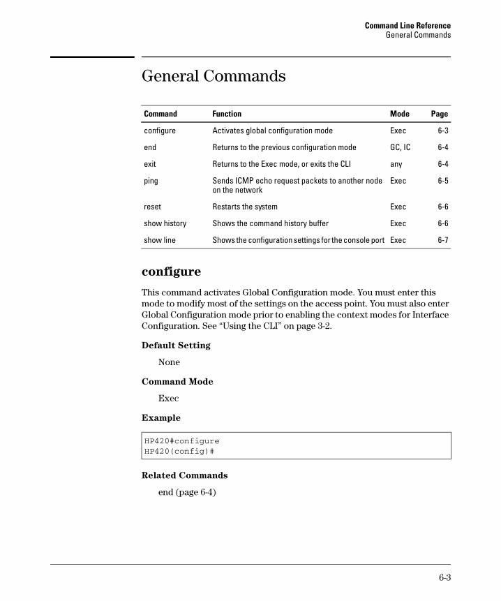
Command Line Reference General Commands
General Commands
Command Function Mode Page
configure Activates global configuration mode Exec 6-3
end Returns to the previous configuration mode GC, IC 6-4
exit Returns to the Exec mode, or exits the CLI any 6-4
ping Sends ICMP echo request packets to another node Exec 6-5 on the network
reset Restarts the system Exec 6-6
show history Shows the command history buffer Exec 6-6
show line Shows the configuration settings for the console port Exec 6-7
configure
This command activates Global Configuration mode. You must enter this mode to modify most of the settings on the access point. You must also enter Global Configuration mode prior to enabling the context modes for Interface Configuration. See “Using the CLI” on page 3-2.
Default Setting
None
Command Mode
Exec
Example
HP420#configureHP420(config)#
Related Commands
end (page 6-4)
6-3
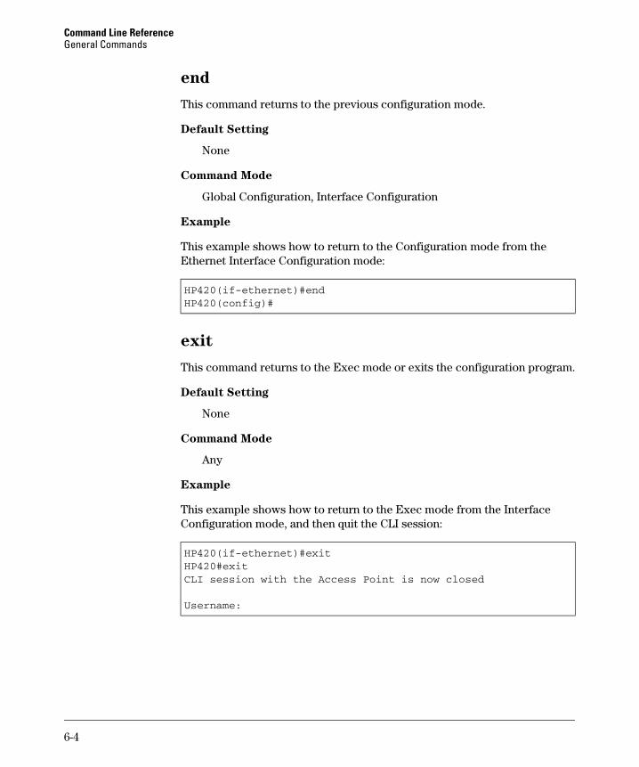
Command Line Reference General Commands
end
This command returns to the previous configuration mode.
Default Setting
None
Command Mode
Global Configuration, Interface Configuration
Example
This example shows how to return to the Configuration mode from the Ethernet Interface Configuration mode:
HP420(if-ethernet)#endHP420(config)#
exit
This command returns to the Exec mode or exits the configuration program.
Default Setting
None
Command Mode
Any
Example
This example shows how to return to the Exec mode from the Interface Configuration mode, and then quit the CLI session:
HP420(if-ethernet)#exitHP420#exitCLI session with the Access Point is now closed
Username:
6-4
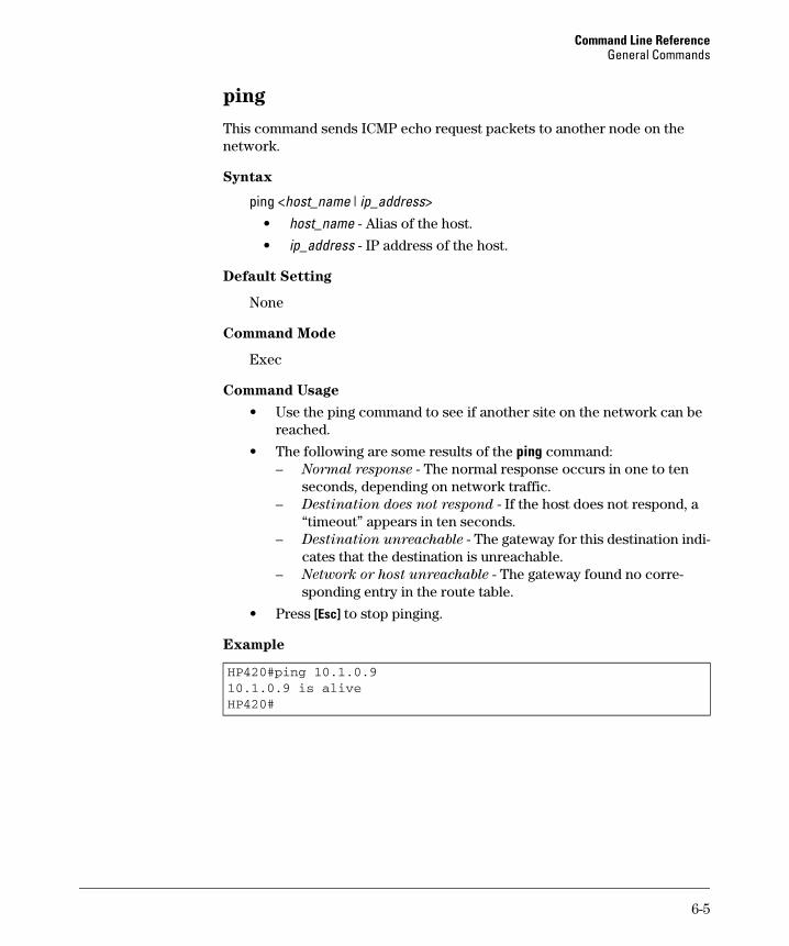
Command Line Reference General Commands
ping
This command sends ICMP echo request packets to another node on the network.
Syntax
ping <host_name | ip_address> • host_name - Alias of the host.
• ip_address - IP address of the host.
Default Setting
None
Command Mode
Exec
Command Usage
• Use the ping command to see if another site on the network can be reached.
• The following are some results of the ping command: – Normal response - The normal response occurs in one to ten
seconds, depending on network traffic. – Destination does not respond - If the host does not respond, a
“timeout” appears in ten seconds. – Destination unreachable - The gateway for this destination indi
cates that the destination is unreachable. – Network or host unreachable - The gateway found no corre
sponding entry in the route table.
• Press [Esc] to stop pinging.
Example
HP420#ping 10.1.0.910.1.0.9 is aliveHP420#
6-5
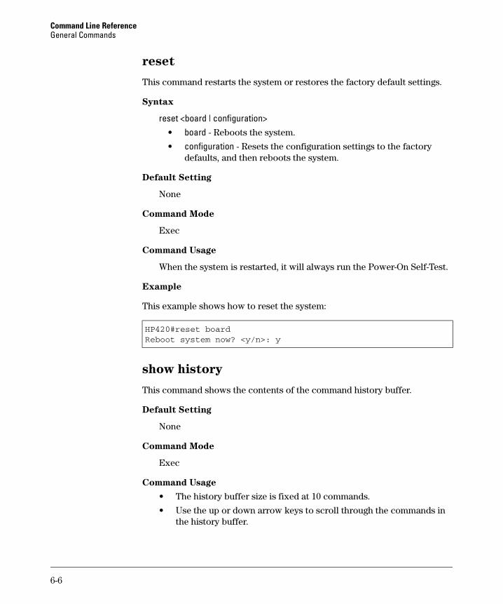
Command Line Reference General Commands
reset
This command restarts the system or restores the factory default settings.
Syntax
reset <board | configuration> • board - Reboots the system.
• configuration - Resets the configuration settings to the factory defaults, and then reboots the system.
Default Setting
None
Command Mode
Exec
Command Usage
When the system is restarted, it will always run the Power-On Self-Test.
Example
This example shows how to reset the system:
HP420#reset boardReboot system now? <y/n>: y
show history
This command shows the contents of the command history buffer.
Default Setting
None
Command Mode
Exec
Command Usage
• The history buffer size is fixed at 10 commands.
• Use the up or down arrow keys to scroll through the commands in the history buffer.
6-6
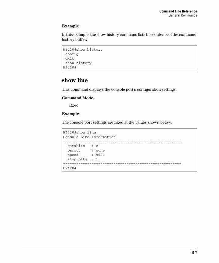
Command Line Reference General Commands
Example
In this example, the show history command lists the contents of the command history buffer:
HP420#show historyconfigexitshow historyHP420#
show line
This command displays the console port’s configuration settings.
Command Mode
Exec
Example
The console port settings are fixed at the values shown below.
HP420#show lineConsole Line Information======================================================databits : 8parity : nonespeed : 9600stop bits : 1
======================================================HP420#
6-7
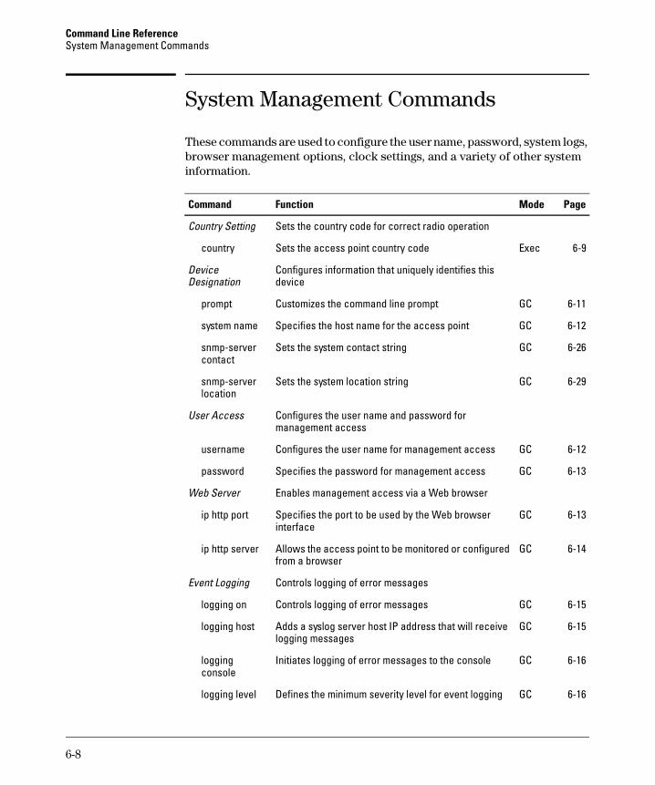
Command Line Reference System Management Commands
System Management Commands
These commands are used to configure the user name, password, system logs, browser management options, clock settings, and a variety of other system information.
Command Function Mode Page
Country Setting
country
Device Designation
prompt
system name
snmp-server contact
snmp-server location
User Access
username
password
Web Server
ip http port
ip http server
Event Logging
logging on
logging host
logging console
Sets the country code for correct radio operation
Sets the access point country code Exec 6-9
Configures information that uniquely identifies this device
Customizes the command line prompt GC 6-11
Specifies the host name for the access point GC 6-12
Sets the system contact string GC 6-26
Sets the system location string GC 6-29
Configures the user name and password for management access
Configures the user name for management access GC 6-12
Specifies the password for management access GC 6-13
Enables management access via a Web browser
Specifies the port to be used by the Web browser GC 6-13 interface
Allows the access point to be monitored or configured GC 6-14 from a browser
Controls logging of error messages
Controls logging of error messages GC 6-15
Adds a syslog server host IP address that will receive GC 6-15 logging messages
Initiates logging of error messages to the console GC 6-16
logging level Defines the minimum severity level for event logging GC 6-16
6-8
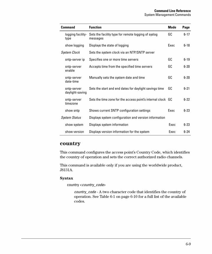
Command Line Reference System Management Commands
Command Function Mode Page
GC 6-17logging facility-type
Sets the facility type for remote logging of syslog messages
show logging Displays the state of logging Exec 6-18
System Clock Sets the system clock via an NTP/SNTP server
sntp-server ip Specifies one or more time servers GC 6-19
sntp-server Accepts time from the specified time servers GC 6-20 enable
sntp-server date-time
Manually sets the system date and time GC 6-20
sntp-server daylight-saving
Sets the start and end dates for daylight savings time GC 6-21
sntp-server timezone
Sets the time zone for the access point’s internal clock GC 6-22
show sntp Shows current SNTP configuration settings Exec 6-23
System Status Displays system configuration and version information
show system Displays system information Exec 6-23
show version Displays version information for the system Exec 6-24
country
This command configures the access point’s Country Code, which identifies the country of operation and sets the correct authorized radio channels.
This command is available only if you are using the worldwide product, J8131A.
Syntax
country <country_code>
country_code - A two character code that identifies the country of operation. See Table 6-1 on page 6-10 for a full list of the available codes.
6-9

Command Line Reference System Management Commands
Table 6-1. Access Point Country Codes
Country Code Country Code Country Code Country Code
Albania AL Dominican Repulic DO Kuwait KW Qatar QA
Algeria DZ Ecuador EC Latvia LV Romania RO
Argentina AR Egypt EG Lebanon LB Russia RU
Armenia AM Estonia EE Liechtenstein LI Saudia Arabia SA
Australia AU Finland FI Lithuania LT Singapore SG
Austria AT France FR Luxembourg LU Slovak Republic SK
Azerbaijan AZ Georgia GE Macau MO Slovenia SI
Bahrain BH Germany DE Macedonia MK South Africa ZA
Belarus BY Greece GR Malaysia MY Spain ES
Belgium BE Guatemala GT Mexico MX Sweden SE
Belize BZ Hong Kong HK Monaco MC Switzerland CH
Bolivia BO Hungary HU Morocco MA Syria SY
Brazil BR Iceland IS North America NA Taiwan TW
Brunei Darussalam BN India IN Netherlands NL Thailand TH
Bulgaria BG Indonesia ID New Zealand NZ Turkey TR
Canada CA Iran IR Norway NO Ukraine UA
Chile CL Ireland IE Oman OM United Arab Emirates AE
China CN Israel IL Pakistan PK United Kingdom GB
Colombia CO Italy IT Panama PA United States US
Costa Rica CR Japan JP Peru PE Uruguay UY
Croatia HR Jordan JO Philippines PH Venezuela VE
Cyprus CY Kazakhstan KZ Poland PL Vietnam VN
Czech Republic CZ North Korea KP Portugal PT
Denmark DK Korea Republic KR Puerto Rico PR
Default Setting
99 (no country set)
6-10
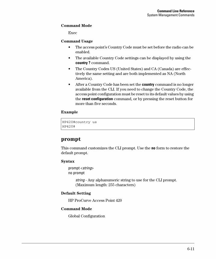
Command Line Reference System Management Commands
Command Mode
Exec
Command Usage
• The access point’s Country Code must be set before the radio can be enabled.
• The available Country Code settings can be displayed by using the country ? command.
• The Country Codes US (United States) and CA (Canada) are effectively the same setting and are both implemented as NA (North America).
• After a Country Code has been set the country command is no longer available from the CLI. If you need to change the Country Code, the access point configuration must be reset to its default values by using the reset configuration command, or by pressing the reset button for more than five seconds.
Example
HP420#country usHP420#
prompt
This command customizes the CLI prompt. Use the no form to restore the default prompt.
Syntax
prompt <string> no prompt
string - Any alphanumeric string to use for the CLI prompt. (Maximum length: 255 characters)
Default Setting
HP ProCurve Access Point 420
Command Mode
Global Configuration
6-11
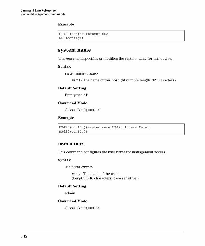
Command Line Reference System Management Commands
Example
HP420(config)#prompt RD2RD2(config)#
system name
This command specifies or modifies the system name for this device.
Syntax
system name <name>
name - The name of this host. (Maximum length: 32 characters)
Default Setting
Enterprise AP
Command Mode
Global Configuration
Example
HP420(config)#system name HP420 Access PointHP420(config)#
username
This command configures the user name for management access.
Syntax
username <name>
name - The name of the user. (Length: 3-16 characters, case sensitive.)
Default Setting
admin
Command Mode
Global Configuration
6-12
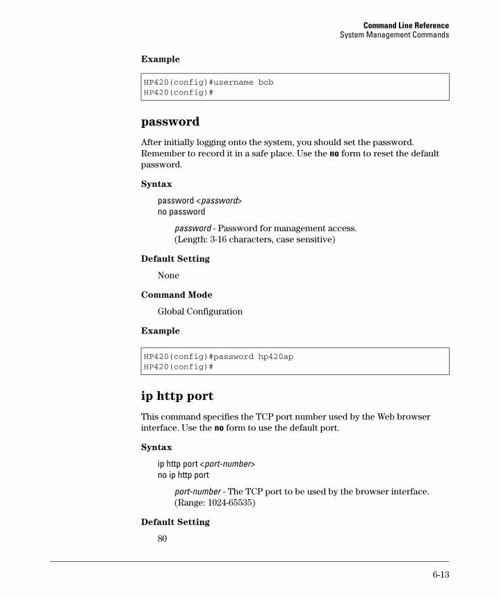
Command Line Reference System Management Commands
Example
HP420(config)#username bobHP420(config)#
password
After initially logging onto the system, you should set the password. Remember to record it in a safe place. Use the no form to reset the default password.
Syntax
password <password> no password
password - Password for management access. (Length: 3-16 characters, case sensitive)
Default Setting
None
Command Mode
Global Configuration
Example
HP420(config)#password hp420apHP420(config)#
ip http port
This command specifies the TCP port number used by the Web browser interface. Use the no form to use the default port.
Syntax
ip http port <port-number> no ip http port
port-number - The TCP port to be used by the browser interface. (Range: 1024-65535)
Default Setting
80
6-13
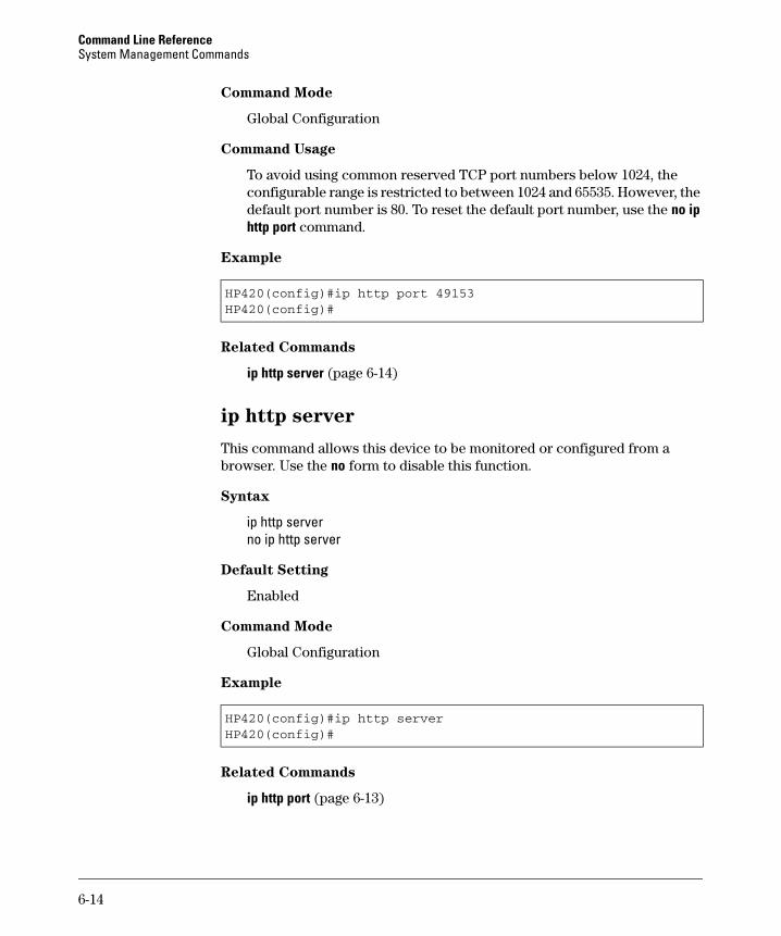
Command Line Reference System Management Commands
Command Mode
Global Configuration
Command Usage
To avoid using common reserved TCP port numbers below 1024, the configurable range is restricted to between 1024 and 65535. However, the default port number is 80. To reset the default port number, use the no ip http port command.
Example
HP420(config)#ip http port 49153HP420(config)#
Related Commands
ip http server (page 6-14)
ip http server
This command allows this device to be monitored or configured from a browser. Use the no form to disable this function.
Syntax
ip http server no ip http server
Default Setting
Enabled
Command Mode
Global Configuration
Example
HP420(config)#ip http serverHP420(config)#
Related Commands
ip http port (page 6-13)
6-14
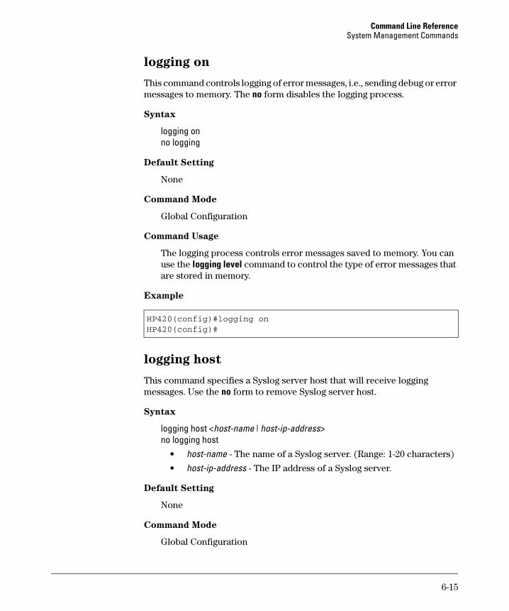
Command Line Reference System Management Commands
logging on
This command controls logging of error messages, i.e., sending debug or error messages to memory. The no form disables the logging process.
Syntax
logging on no logging
Default Setting
None
Command Mode
Global Configuration
Command Usage
The logging process controls error messages saved to memory. You can use the logging level command to control the type of error messages that are stored in memory.
Example
HP420(config)#logging onHP420(config)#
logging host
This command specifies a Syslog server host that will receive logging messages. Use the no form to remove Syslog server host.
Syntax
logging host <host-name | host-ip-address> no logging host
• host-name - The name of a Syslog server. (Range: 1-20 characters)
• host-ip-address - The IP address of a Syslog server.
Default Setting
None
Command Mode
Global Configuration
6-15
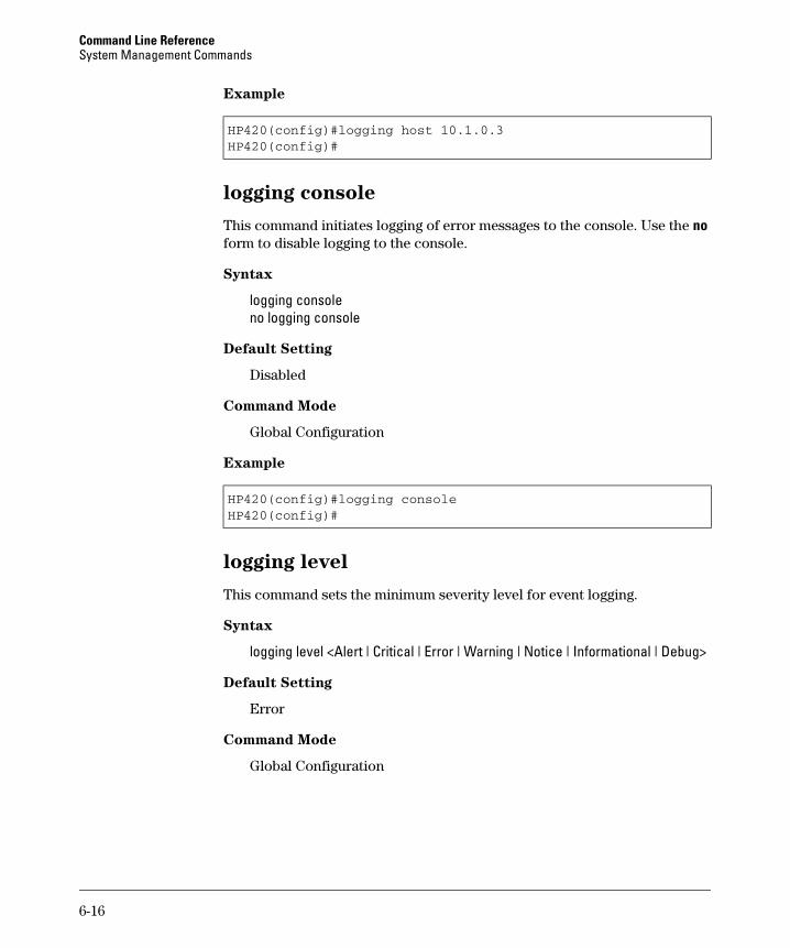
Command Line Reference System Management Commands
Example
HP420(config)#logging host 10.1.0.3HP420(config)#
logging console
This command initiates logging of error messages to the console. Use the no form to disable logging to the console.
Syntax
logging console no logging console
Default Setting
Disabled
Command Mode
Global Configuration
Example
HP420(config)#logging consoleHP420(config)#
logging level
This command sets the minimum severity level for event logging.
Syntax
logging level <Alert | Critical | Error | Warning | Notice | Informational | Debug>
Default Setting
Error
Command Mode
Global Configuration
6-16
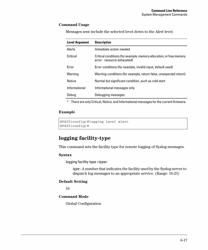
Command Line Reference System Management Commands
Command Usage
Messages sent include the selected level down to the Alert level.
Level Argument Description
Alerts Immediate action needed
Critical Critical conditions (for example, memory allocation, or free memory error - resource exhausted)
Error Error conditions (for example, invalid input, default used)
Warning Warning conditions (for example, return false, unexpected return)
Notice Normal but significant condition, such as cold start
Informational Informational messages only
Debug Debugging messages
* There are only Critical, Notice, and Informational messages for the current firmware.
Example
HP420(config)#logging level alertHP420(config)#
logging facility-type
This command sets the facility type for remote logging of Syslog messages.
Syntax
logging facility-type <type>
type - A number that indicates the facility used by the Syslog server to dispatch log messages to an appropriate service. (Range: 16-23)
Default Setting
16
Command Mode
Global Configuration
6-17

Command Line Reference System Management Commands
Command Usage
The command specifies the facility type tag sent in Syslog messages. (See RFC 3164.) This type has no effect on the kind of messages reported by the access point. However, it may be used by the Syslog server to sort messages or to store messages in the corresponding database.
Example
HP420(config)#logging facility 19HP420(config)#
show logging
This command displays the logging configuration.
Syntax
show logging
Command Mode
Exec
Example
HP420#show logging
Logging Information============================================Syslog State : DisabledLogging Host State : EnabledLogging Console State : DisabledServer Domain name/IP : noneLogging Level : ErrorLogging Facility Type : 16=============================================
HP420#
6-18
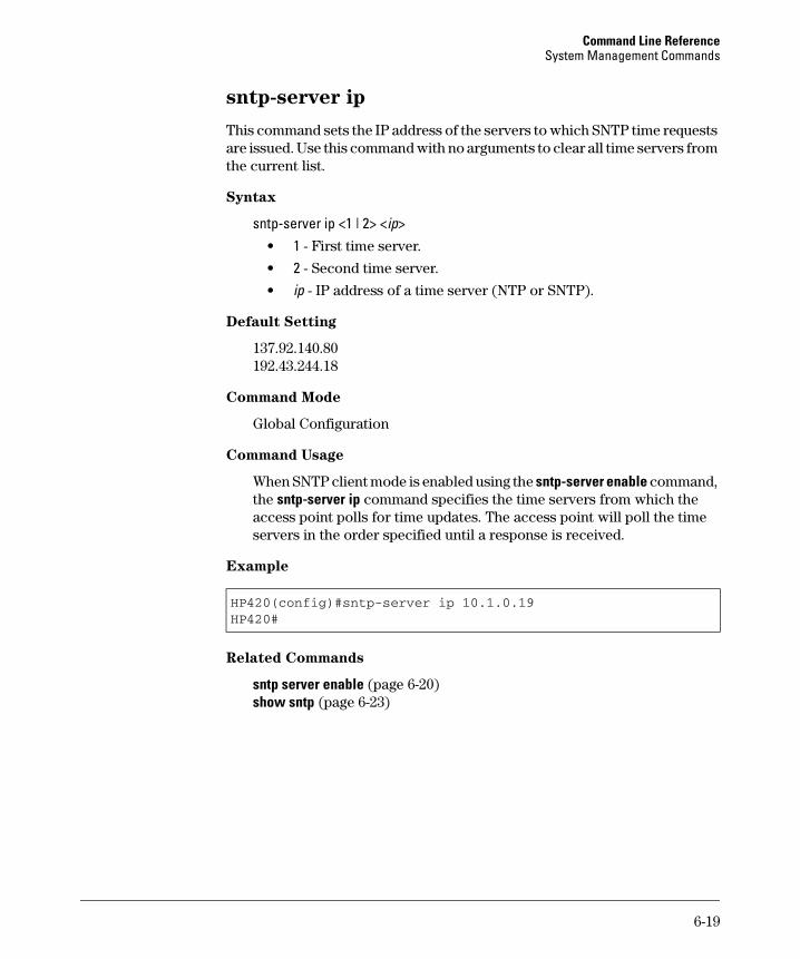
Command Line Reference System Management Commands
sntp-server ip
This command sets the IP address of the servers to which SNTP time requests are issued. Use this command with no arguments to clear all time servers from the current list.
Syntax
sntp-server ip <1 | 2> <ip> • 1 - First time server.
• 2 - Second time server.
• ip - IP address of a time server (NTP or SNTP).
Default Setting
137.92.140.80 192.43.244.18
Command Mode
Global Configuration
Command Usage
When SNTP client mode is enabled using the sntp-server enable command, the sntp-server ip command specifies the time servers from which the access point polls for time updates. The access point will poll the time servers in the order specified until a response is received.
Example
HP420(config)#sntp-server ip 10.1.0.19HP420#
Related Commands
sntp server enable (page 6-20) show sntp (page 6-23)
6-19
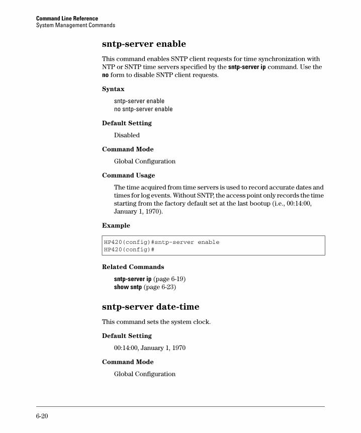
Command Line Reference System Management Commands
sntp-server enable
This command enables SNTP client requests for time synchronization with NTP or SNTP time servers specified by the sntp-server ip command. Use the no form to disable SNTP client requests.
Syntax
sntp-server enable no sntp-server enable
Default Setting
Disabled
Command Mode
Global Configuration
Command Usage
The time acquired from time servers is used to record accurate dates and times for log events. Without SNTP, the access point only records the time starting from the factory default set at the last bootup (i.e., 00:14:00, January 1, 1970).
Example
HP420(config)#sntp-server enableHP420(config)#
Related Commands
sntp-server ip (page 6-19) show sntp (page 6-23)
sntp-server date-time
This command sets the system clock.
Default Setting
00:14:00, January 1, 1970
Command Mode
Global Configuration
6-20

Command Line Reference System Management Commands
Example
This example sets the system clock to 17:37 June 19, 2003.
HP420#sntp-server date-timeEnter Year<1970-2100>: 2003Enter Month<1-12>: 6Enter Day<1-31>: 19Enter Hour<0-23>: 17Enter Min<0-59>: 37HP420#
Related Commands
sntp-server enable (page 6-20)
sntp-server daylight-saving
This command sets the start and end dates for daylight savings time. Use the no form to disable daylight savings time.
Syntax
sntp-server daylight-saving no sntp-server daylight-saving
Default Setting
Disabled
Command Mode
Global Configuration
Command Usage
The command sets the system clock back one hour during the specified-period.
6-21
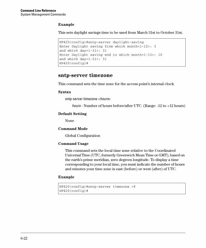
Command Line Reference System Management Commands
Example
This sets daylight savings time to be used from March 31st to October 31st.
HP420(config)#sntp-server daylight-savingEnter Daylight saving from which month<1-12>: 3and which day<1-31>: 31Enter Daylight saving end to which month<1-12>: 10and which day<1-31>: 31HP420(config)#
sntp-server timezone
This command sets the time zone for the access point’s internal clock.
Syntax
sntp-server timezone <hours>
hours - Number of hours before/after UTC. (Range: -12 to +12 hours)
Default Setting
None
Command Mode
Global Configuration
Command Usage
This command sets the local time zone relative to the Coordinated Universal Time (UTC, formerly Greenwich Mean Time or GMT), based on the earth’s prime meridian, zero degrees longitude. To display a time corresponding to your local time, you must indicate the number of hours and minutes your time zone is east (before) or west (after) of UTC.
Example
HP420(config)#sntp-server timezone +8HP420(config)#
6-22
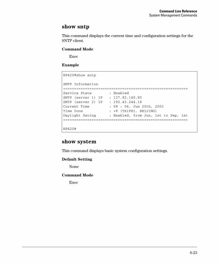
Command Line Reference System Management Commands
show sntp
This command displays the current time and configuration settings for the SNTP client.
Command Mode
Exec
Example
HP420#show sntp
SNTP Information=========================================================Service State : EnabledSNTP (server 1) IP : 137.92.140.80SNTP (server 2) IP : 192.43.244.18Current Time : 08 : 04, Jun 20th, 2003Time Zone : +8 (TAIPEI, BEIJING)Daylight Saving : Enabled, from Jun, 1st to Sep, 1st=========================================================
HP420#
show system
This command displays basic system configuration settings.
Default Setting
None
Command Mode
Exec
6-23
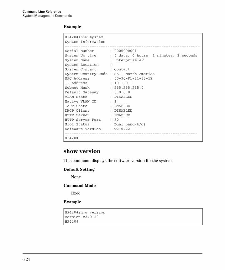
Command Line Reference System Management Commands
Example
HP420#show systemSystem Information============================================================Serial Number : 0000000001System Up time : 0 days, 0 hours, 1 minutes, 3 secondsSystem Name : Enterprise APSystem Location :System Contact : ContactSystem Country Code : NA - North AmericaMAC Address : 00-30-F1-81-83-12IP Address : 10.1.0.1Subnet Mask : 255.255.255.0Default Gateway : 0.0.0.0VLAN State : DISABLEDNative VLAN ID : 1IAPP State : ENABLEDDHCP Client : DISABLEDHTTP Server : ENABLEDHTTP Server Port : 80Slot Status : Dual band(b/g)Software Version : v2.0.22===========================================================HP420#
show version
This command displays the software version for the system.
Default Setting
None
Command Mode
Exec
Example
HP420#show versionVersion v2.0.22HP420#
6-24
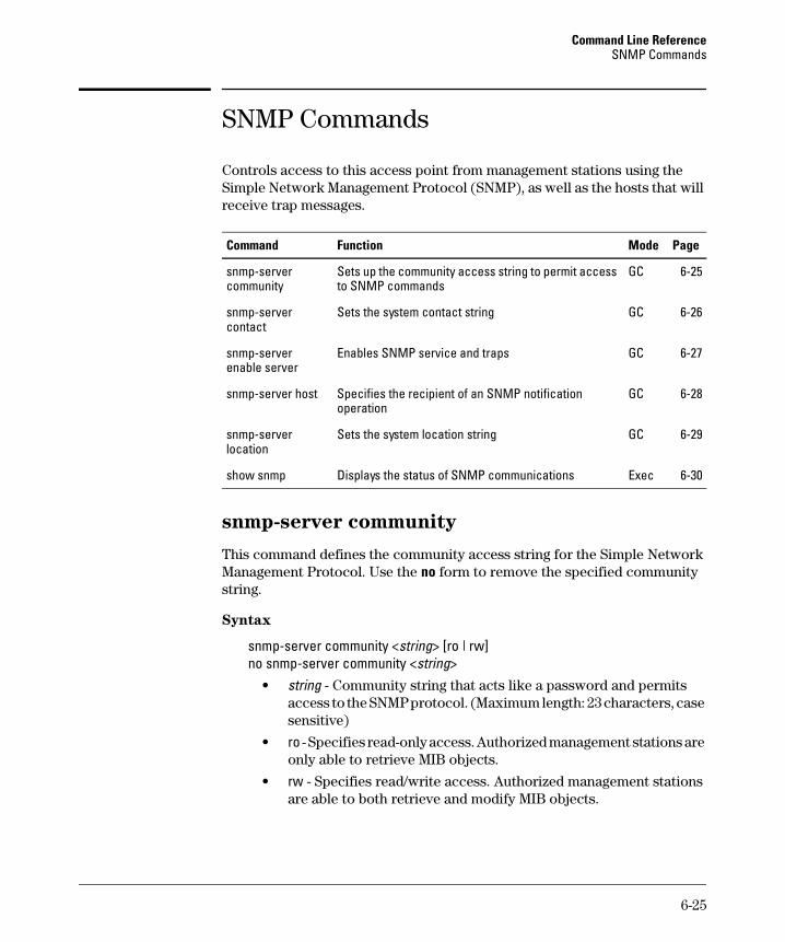
Command Line Reference SNMP Commands
SNMP Commands
Controls access to this access point from management stations using the Simple Network Management Protocol (SNMP), as well as the hosts that will receive trap messages.
Command Function Mode Page
snmp-server community
Sets up the community access string to permit access to SNMP commands
GC 6-25
snmp-server contact
Sets the system contact string GC 6-26
snmp-server enable server
Enables SNMP service and traps GC 6-27
snmp-server host Specifies the recipient of an SNMP notification operation
GC 6-28
snmp-server location
Sets the system location string GC 6-29
show snmp Displays the status of SNMP communications Exec 6-30
snmp-server community
This command defines the community access string for the Simple Network Management Protocol. Use the no form to remove the specified community string.
Syntax
snmp-server community <string> [ro | rw] no snmp-server community <string>
• string - Community string that acts like a password and permits access to the SNMP protocol. (Maximum length: 23 characters, case sensitive)
• ro - Specifies read-only access. Authorized management stations are only able to retrieve MIB objects.
• rw - Specifies read/write access. Authorized management stations are able to both retrieve and modify MIB objects.
6-25
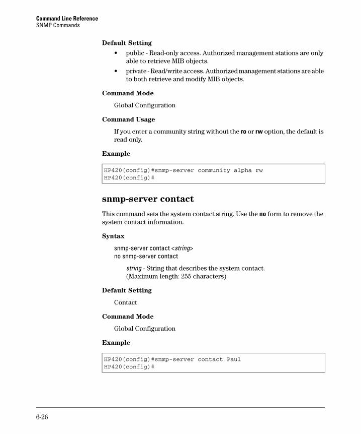
Command Line Reference SNMP Commands
Default Setting
• public - Read-only access. Authorized management stations are only able to retrieve MIB objects.
• private - Read/write access. Authorized management stations are able to both retrieve and modify MIB objects.
Command Mode
Global Configuration
Command Usage
If you enter a community string without the ro or rw option, the default is read only.
Example
HP420(config)#snmp-server community alpha rwHP420(config)#
snmp-server contact
This command sets the system contact string. Use the no form to remove the system contact information.
Syntax
snmp-server contact <string> no snmp-server contact
string - String that describes the system contact. (Maximum length: 255 characters)
Default Setting
Contact
Command Mode
Global Configuration
Example
HP420(config)#snmp-server contact PaulHP420(config)#
6-26
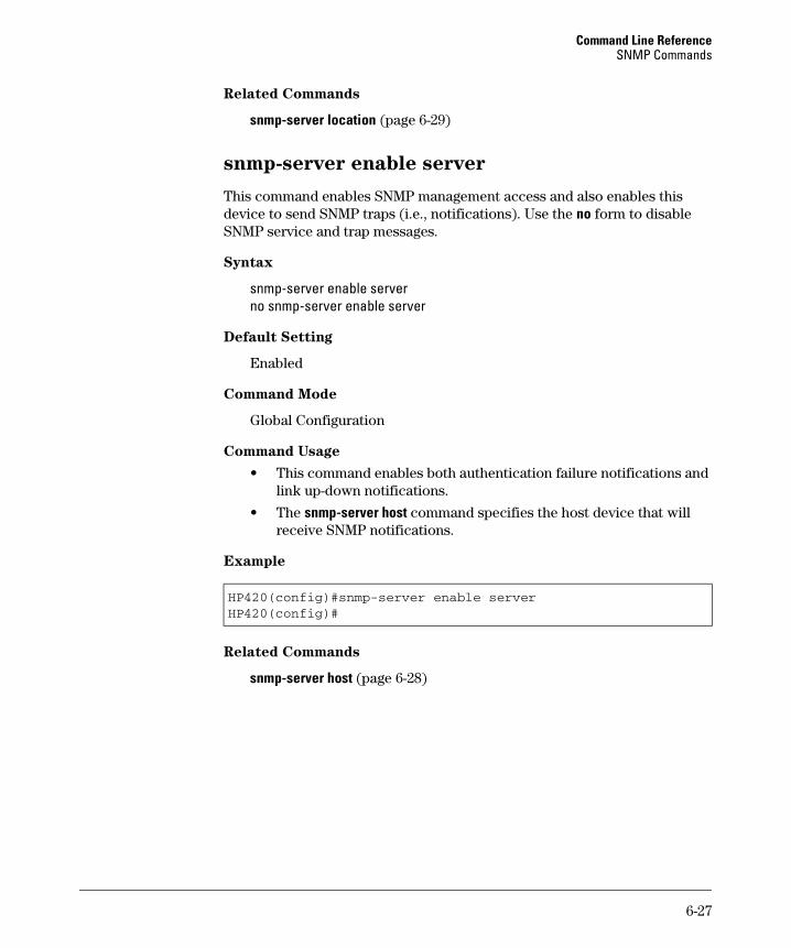
Command Line Reference SNMP Commands
Related Commands
snmp-server location (page 6-29)
snmp-server enable server
This command enables SNMP management access and also enables this device to send SNMP traps (i.e., notifications). Use the no form to disable SNMP service and trap messages.
Syntax
snmp-server enable server no snmp-server enable server
Default Setting
Enabled
Command Mode
Global Configuration
Command Usage
• This command enables both authentication failure notifications and link up-down notifications.
• The snmp-server host command specifies the host device that will receive SNMP notifications.
Example
HP420(config)#snmp-server enable serverHP420(config)#
Related Commands
snmp-server host (page 6-28)
6-27
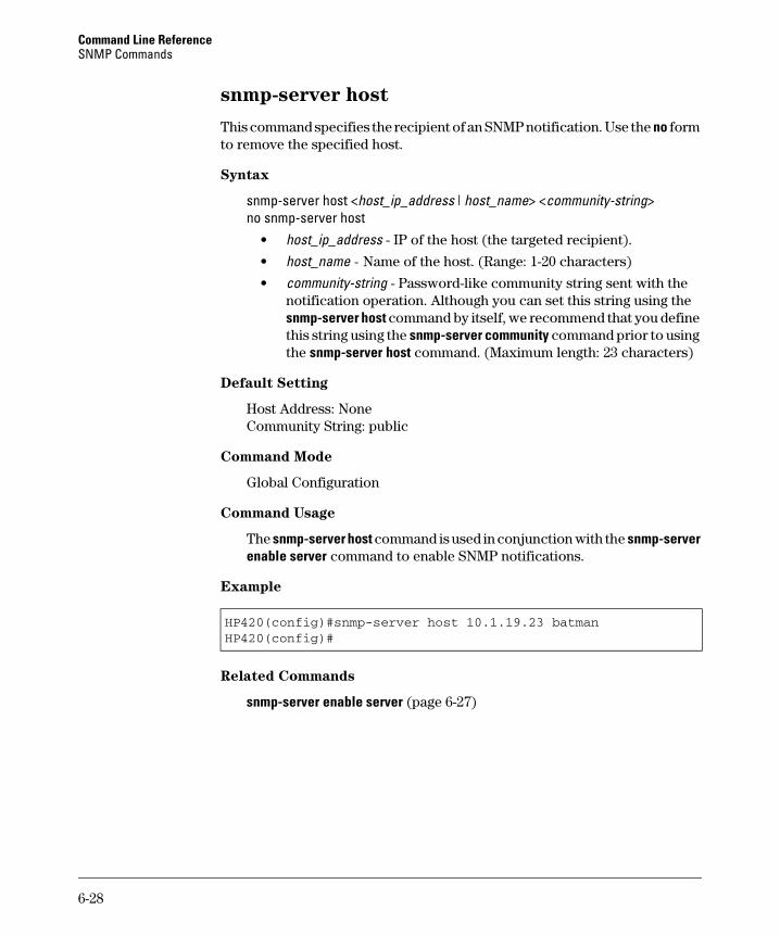
Command Line Reference SNMP Commands
snmp-server host
This command specifies the recipient of an SNMP notification. Use the no form to remove the specified host.
Syntax
snmp-server host <host_ip_address | host_name> <community-string> no snmp-server host
• host_ip_address - IP of the host (the targeted recipient).
• host_name - Name of the host. (Range: 1-20 characters)
• community-string - Password-like community string sent with the notification operation. Although you can set this string using the snmp-server host command by itself, we recommend that you define this string using the snmp-server community command prior to using the snmp-server host command. (Maximum length: 23 characters)
Default Setting
Host Address: None Community String: public
Command Mode
Global Configuration
Command Usage
The snmp-server host command is used in conjunction with the snmp-server enable server command to enable SNMP notifications.
Example
HP420(config)#snmp-server host 10.1.19.23 batmanHP420(config)#
Related Commands
snmp-server enable server (page 6-27)
6-28
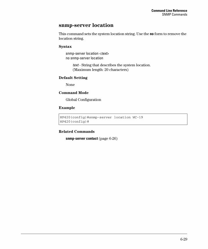
Command Line Reference SNMP Commands
snmp-server location
This command sets the system location string. Use the no form to remove the location string.
Syntax
snmp-server location <text> no snmp-server location
text - String that describes the system location. (Maximum length: 20 characters)
Default Setting
None
Command Mode
Global Configuration
Example
HP420(config)#snmp-server location WC-19HP420(config)#
Related Commands
snmp-server contact (page 6-26)
6-29
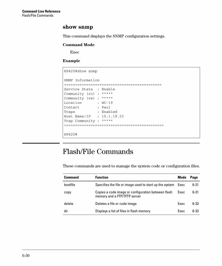
Command Line Reference Flash/File Commands
show snmp
This command displays the SNMP configuration settings.
Command Mode
Exec
Example
HP420#show snmp
SNMP Information============================================Service State : EnableCommunity (ro) : *****Community (rw) : *****Location : WC-19Contact : PaulTraps : EnabledHost Name/IP : 10.1.19.23Trap Community : *****=============================================
HP420#
Flash/File Commands
These commands are used to manage the system code or configuration files.
Command Function Mode Page
bootfile Specifies the file or image used to start up the system Exec 6-31
copy Copies a code image or configuration between flash Exec 6-31 memory and a FTP/TFTP server
delete Deletes a file or code image Exec 6-33
dir Displays a list of files in flash memory Exec 6-33
6-30
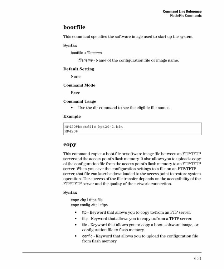
Command Line Reference Flash/File Commands
bootfile
This command specifies the software image used to start up the system.
Syntax
bootfile <filename>
filename - Name of the configuration file or image name.
Default Setting
None
Command Mode
Exec
Command Usage
• Use the dir command to see the eligible file names.
Example
HP420#bootfile hp420-2.binHP420#
copy
This command copies a boot file or software image file between an FTP/TFTP server and the access point’s flash memory. It also allows you to upload a copy of the configuration file from the access point’s flash memory to an FTP/TFTP server. When you save the configuration settings to a file on an FTP/TFTP server, that file can later be downloaded to the access point to restore system operation. The success of the file transfer depends on the accessibility of the FTP/TFTP server and the quality of the network connection.
Syntax
copy <ftp | tftp> file copy config <ftp | tftp>
• ftp - Keyword that allows you to copy to/from an FTP server.
• tftp - Keyword that allows you to copy to/from a TFTP server.
• file - Keyword that allows you to copy a boot, software image, or configuration file to flash memory.
• config - Keyword that allows you to upload the configuration file from flash memory.
6-31
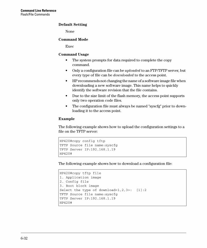
Command Line Reference Flash/File Commands
Default Setting
None
Command Mode
Exec
Command Usage
• The system prompts for data required to complete the copy command.
• Only a configuration file can be uploaded to an FTP/TFTP server, but every type of file can be downloaded to the access point.
• HP recommends not changing the name of a software image file when downloading a new software image. This name helps to quickly identify the software revision that the file contains.
• Due to the size limit of the flash memory, the access point supports only two operation code files.
• The configuration file must always be named "syscfg" prior to down-loading it to the access point.
Example
The following example shows how to upload the configuration settings to a file on the TFTP server:
HP420#copy config tftpTFTP Source file name:syscfgTFTP Server IP:192.168.1.19HP420#
The following example shows how to download a configuration file:
HP420#copy tftp file1. Application image2. Config file3. Boot block imageSelect the type of download<1,2,3>: [1]:2TFTP Source file name:syscfgTFTP Server IP:192.168.1.19HP420#
6-32
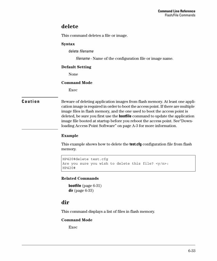
Command Line Reference Flash/File Commands
delete
This command deletes a file or image.
Syntax
delete filename
filename - Name of the configuration file or image name.
Default Setting
None
Command Mode
Exec
C a u t i o n Beware of deleting application images from flash memory. At least one application image is required in order to boot the access point. If there are multiple image files in flash memory, and the one used to boot the access point is deleted, be sure you first use the bootfile command to update the application image file booted at startup before you reboot the access point. See“Down-loading Access Point Software” on page A-3 for more information.
Example
This example shows how to delete the test.cfg configuration file from flash memory.
HP420#delete test.cfgAre you sure you wish to delete this file? <y/n>:HP420#
Related Commands
bootfile (page 6-31) dir (page 6-33)
dir
This command displays a list of files in flash memory.
Command Mode
Exec
6-33
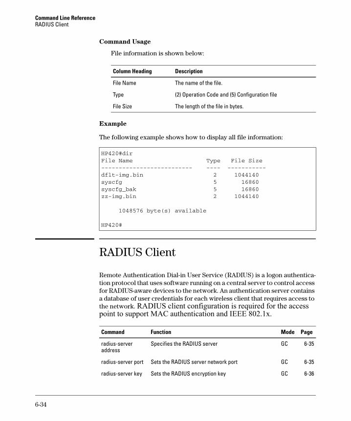
Command Line Reference RADIUS Client
-------------------------- ---------------
Command Usage
File information is shown below:
Column Heading Description
File Name The name of the file.
Type (2) Operation Code and (5) Configuration file
File Size The length of the file in bytes.
Example
The following example shows how to display all file information:
HP420#dirFile Name Type File Size
dflt-img.bin 2 1044140syscfg 5 16860syscfg_bak 5 16860zz-img.bin 2 1044140
1048576 byte(s) available
HP420#
RADIUS Client
Remote Authentication Dial-in User Service (RADIUS) is a logon authentication protocol that uses software running on a central server to control access for RADIUS-aware devices to the network. An authentication server contains a database of user credentials for each wireless client that requires access to the network. RADIUS client configuration is required for the access point to support MAC authentication and IEEE 802.1x.
Command Function Mode Page
radius-server Specifies the RADIUS server GC 6-35 address
radius-server port Sets the RADIUS server network port GC 6-35
radius-server key Sets the RADIUS encryption key GC 6-36
6-34
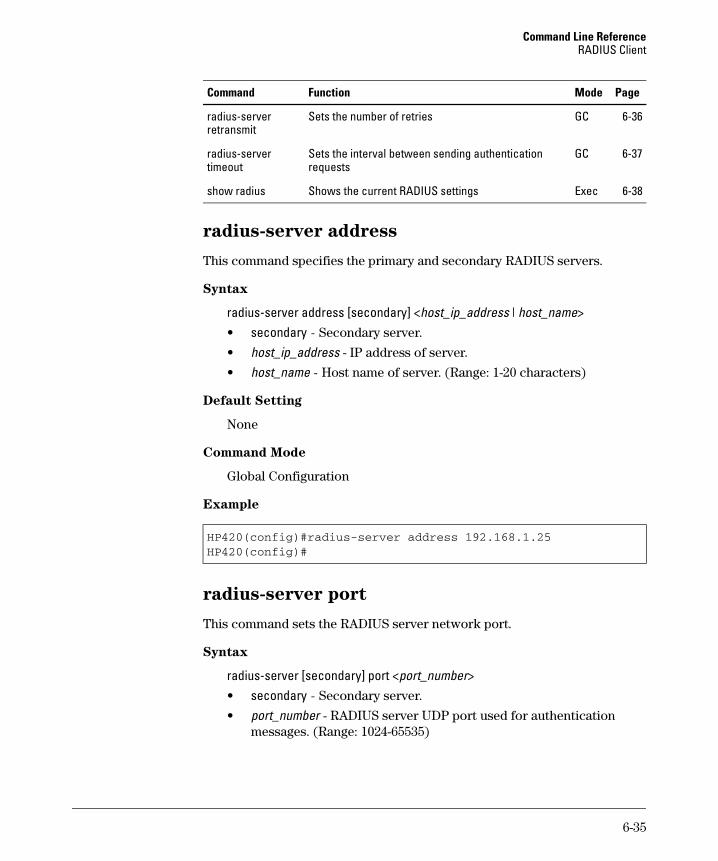
Command Line Reference RADIUS Client
Command Function Mode Page
Sets the number of retries GC 6-36radius-server retransmit
radius-server timeout
Sets the interval between sending authentication requests
GC 6-37
show radius Shows the current RADIUS settings Exec 6-38
radius-server address
This command specifies the primary and secondary RADIUS servers.
Syntax
radius-server address [secondary] <host_ip_address | host_name> • secondary - Secondary server.
• host_ip_address - IP address of server.
• host_name - Host name of server. (Range: 1-20 characters)
Default Setting
None
Command Mode
Global Configuration
Example
HP420(config)#radius-server address 192.168.1.25HP420(config)#
radius-server port
This command sets the RADIUS server network port.
Syntax
radius-server [secondary] port <port_number> • secondary - Secondary server.
• port_number - RADIUS server UDP port used for authentication messages. (Range: 1024-65535)
6-35
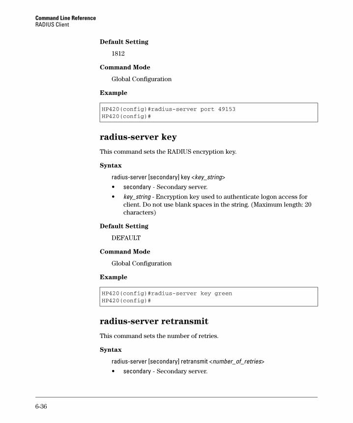
Command Line Reference RADIUS Client
Default Setting
1812
Command Mode
Global Configuration
Example
HP420(config)#radius-server port 49153HP420(config)#
radius-server key
This command sets the RADIUS encryption key.
Syntax
radius-server [secondary] key <key_string> • secondary - Secondary server.
• key_string - Encryption key used to authenticate logon access for client. Do not use blank spaces in the string. (Maximum length: 20 characters)
Default Setting
DEFAULT
Command Mode
Global Configuration
Example
HP420(config)#radius-server key greenHP420(config)#
radius-server retransmit
This command sets the number of retries.
Syntax
radius-server [secondary] retransmit <number_of_retries> • secondary - Secondary server.
6-36
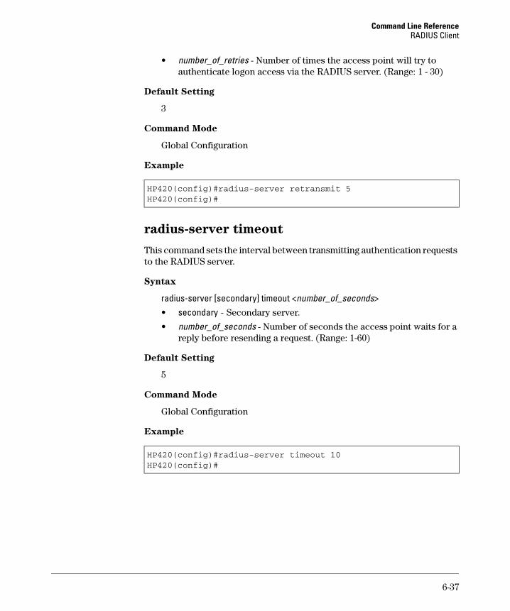
Command Line Reference RADIUS Client
• number_of_retries - Number of times the access point will try to authenticate logon access via the RADIUS server. (Range: 1 - 30)
Default Setting
3
Command Mode
Global Configuration
Example
HP420(config)#radius-server retransmit 5HP420(config)#
radius-server timeout
This command sets the interval between transmitting authentication requests to the RADIUS server.
Syntax
radius-server [secondary] timeout <number_of_seconds> • secondary - Secondary server.
• number_of_seconds - Number of seconds the access point waits for a reply before resending a request. (Range: 1-60)
Default Setting
5
Command Mode
Global Configuration
Example
HP420(config)#radius-server timeout 10HP420(config)#
6-37
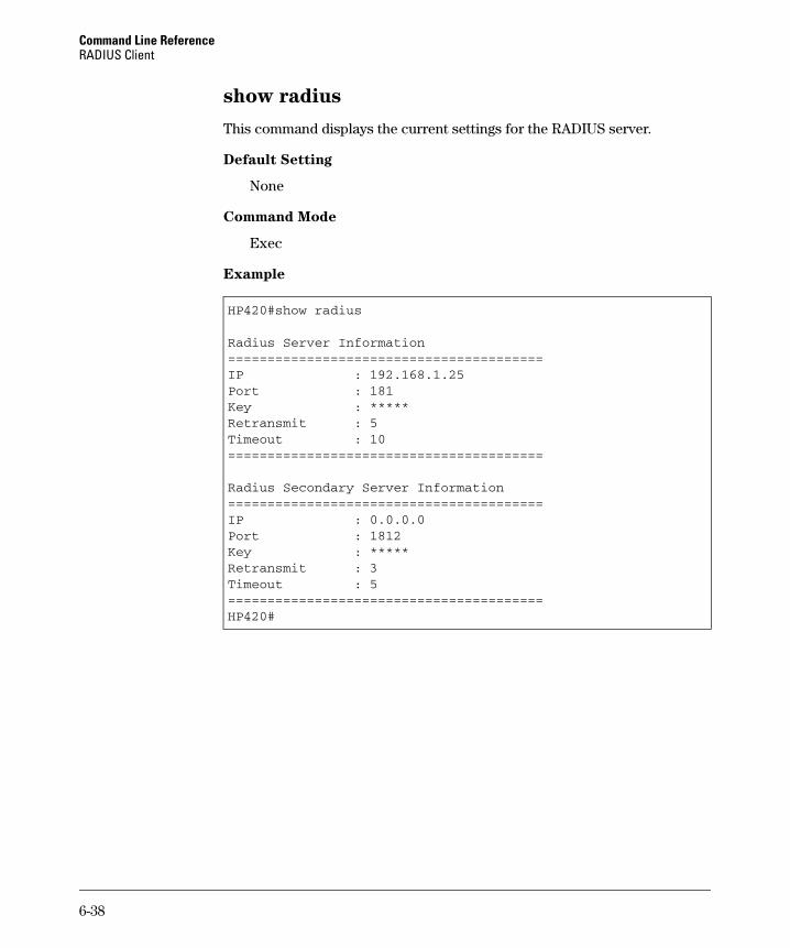
Command Line Reference RADIUS Client
show radius
This command displays the current settings for the RADIUS server.
Default Setting
None
Command Mode
Exec
Example
HP420#show radius
Radius Server Information========================================IP : 192.168.1.25Port : 181Key : *****Retransmit : 5Timeout : 10========================================
Radius Secondary Server Information========================================IP : 0.0.0.0Port : 1812Key : *****Retransmit : 3Timeout : 5========================================HP420#
6-38
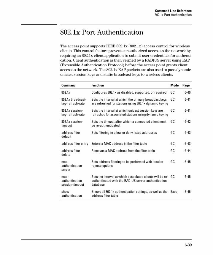
Command Line Reference 802.1x Port Authentication
802.1x Port Authentication
The access point supports IEEE 802.1x (802.1x) access control for wireless clients. This control feature prevents unauthorized access to the network by requiring an 802.1x client application to submit user credentials for authentication. Client authentication is then verified by a RADIUS server using EAP (Extensible Authentication Protocol) before the access point grants client access to the network. The 802.1x EAP packets are also used to pass dynamic unicast session keys and static broadcast keys to wireless clients.
Command Function Mode Page
802.1x Configures 802.1x as disabled, supported, or required GC 6-40
802.1x broadcast- Sets the interval at which the primary broadcast keys GC 6-41 key-refresh-rate are refreshed for stations using 802.1x dynamic keying
802.1x session- Sets the interval at which unicast session keys are GC 6-41 key-refresh-rate refreshed for associated stations using dynamic keying
802.1x session- Sets the timeout after which a connected client must GC 6-42 timeout be re-authenticated
address filter Sets filtering to allow or deny listed addresses GC 6-43 default
address filter entry Enters a MAC address in the filter table GC 6-43
address filter Removes a MAC address from the filter table GC 6-44 delete
mac- Sets address filtering to be performed with local or GC 6-45 authentication remote options server
mac- Sets the interval at which associated clients will be re- GC 6-45 authentication authenticated with the RADIUS server authentication session-timeout database
show Shows all 802.1x authentication settings, as well as the Exec 6-46 authentication address filter table
6-39
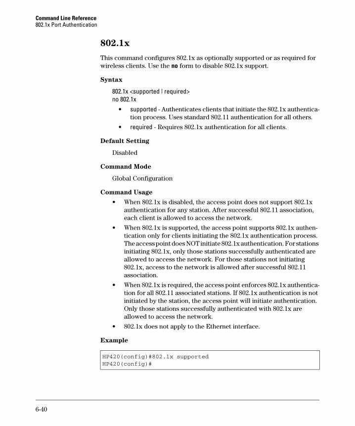
Command Line Reference 802.1x Port Authentication
802.1x
This command configures 802.1x as optionally supported or as required for wireless clients. Use the no form to disable 802.1x support.
Syntax
802.1x <supported | required> no 802.1x
• supported - Authenticates clients that initiate the 802.1x authentication process. Uses standard 802.11 authentication for all others.
• required - Requires 802.1x authentication for all clients.
Default Setting
Disabled
Command Mode
Global Configuration
Command Usage
• When 802.1x is disabled, the access point does not support 802.1x authentication for any station. After successful 802.11 association, each client is allowed to access the network.
• When 802.1x is supported, the access point supports 802.1x authentication only for clients initiating the 802.1x authentication process. The access point does NOT initiate 802.1x authentication. For stations initiating 802.1x, only those stations successfully authenticated are allowed to access the network. For those stations not initiating 802.1x, access to the network is allowed after successful 802.11 association.
• When 802.1x is required, the access point enforces 802.1x authentication for all 802.11 associated stations. If 802.1x authentication is not initiated by the station, the access point will initiate authentication. Only those stations successfully authenticated with 802.1x are allowed to access the network.
• 802.1x does not apply to the Ethernet interface.
Example
HP420(config)#802.1x supportedHP420(config)#
6-40
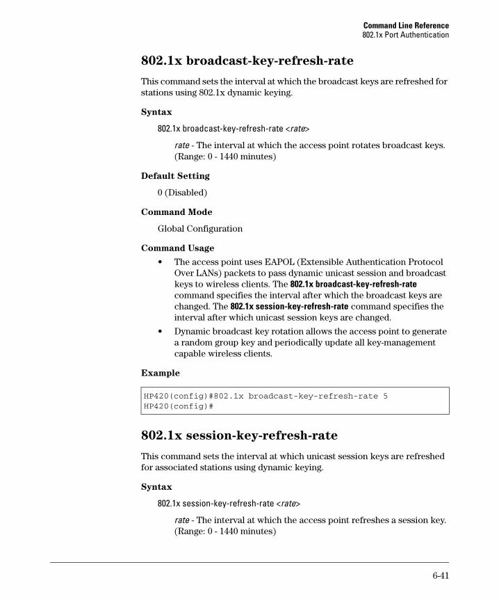
Command Line Reference 802.1x Port Authentication
802.1x broadcast-key-refresh-rate
This command sets the interval at which the broadcast keys are refreshed for stations using 802.1x dynamic keying.
Syntax
802.1x broadcast-key-refresh-rate <rate>
rate - The interval at which the access point rotates broadcast keys. (Range: 0 - 1440 minutes)
Default Setting
0 (Disabled)
Command Mode
Global Configuration
Command Usage
• The access point uses EAPOL (Extensible Authentication Protocol Over LANs) packets to pass dynamic unicast session and broadcast keys to wireless clients. The 802.1x broadcast-key-refresh-rate command specifies the interval after which the broadcast keys are changed. The 802.1x session-key-refresh-rate command specifies the interval after which unicast session keys are changed.
• Dynamic broadcast key rotation allows the access point to generate a random group key and periodically update all key-management capable wireless clients.
Example
HP420(config)#802.1x broadcast-key-refresh-rate 5HP420(config)#
802.1x session-key-refresh-rate
This command sets the interval at which unicast session keys are refreshed for associated stations using dynamic keying.
Syntax
802.1x session-key-refresh-rate <rate>
rate - The interval at which the access point refreshes a session key. (Range: 0 - 1440 minutes)
6-41
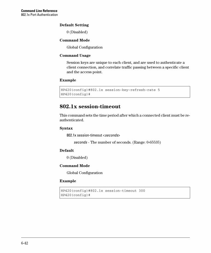
Command Line Reference 802.1x Port Authentication
Default Setting
0 (Disabled)
Command Mode
Global Configuration
Command Usage
Session keys are unique to each client, and are used to authenticate a client connection, and correlate traffic passing between a specific client and the access point.
Example
HP420(config)#802.1x session-key-refresh-rate 5HP420(config)#
802.1x session-timeout
This command sets the time period after which a connected client must be re-authenticated.
Syntax
802.1x session-timeout <seconds>
seconds - The number of seconds. (Range: 0-65535)
Default
0 (Disabled)
Command Mode
Global Configuration
Example
HP420(config)#802.1x session-timeout 300HP420(config)#
6-42
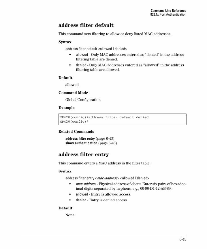
Command Line Reference 802.1x Port Authentication
address filter default
This command sets filtering to allow or deny listed MAC addresses.
Syntax
address filter default <allowed | denied> • allowed - Only MAC addresses entered as “denied” in the address
filtering table are denied.
• denied - Only MAC addresses entered as “allowed” in the address filtering table are allowed.
Default
allowed
Command Mode
Global Configuration
Example
HP420(config)#address filter default deniedHP420(config)#
Related Commands
address filter entry (page 6-43) show authentication (page 6-46)
address filter entry
This command enters a MAC address in the filter table.
Syntax
address filter entry <mac-address> <allowed | denied> • mac-address - Physical address of client. Enter six pairs of hexadec
imal digits separated by hyphens, e.g., 00-90-D1-12-AB-89.
• allowed - Entry is allowed access.
• denied - Entry is denied access.
Default
None
6-43
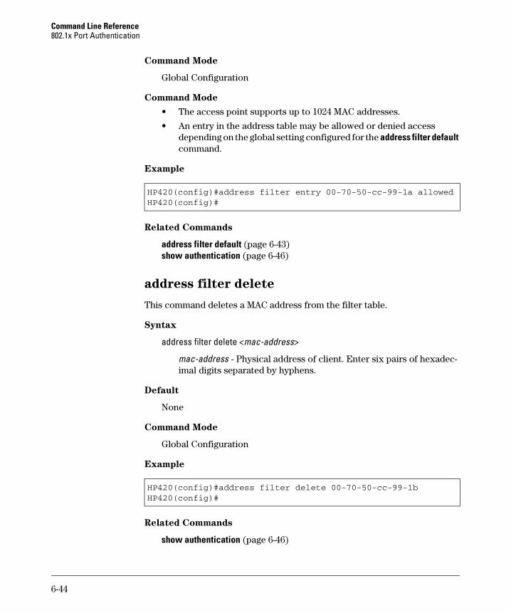
Command Line Reference 802.1x Port Authentication
Command Mode
Global Configuration
Command Mode
• The access point supports up to 1024 MAC addresses.
• An entry in the address table may be allowed or denied access depending on the global setting configured for the address filter default command.
Example
HP420(config)#address filter entry 00-70-50-cc-99-1a allowedHP420(config)#
Related Commands
address filter default (page 6-43) show authentication (page 6-46)
address filter delete
This command deletes a MAC address from the filter table.
Syntax
address filter delete <mac-address>
mac-address - Physical address of client. Enter six pairs of hexadecimal digits separated by hyphens.
Default
None
Command Mode
Global Configuration
Example
HP420(config)#address filter delete 00-70-50-cc-99-1b HP420(config)#
Related Commands
show authentication (page 6-46)
6-44

Command Line Reference 802.1x Port Authentication
mac-authentication server
This command sets address filtering to be performed with local or remote options. Use the no form to disable MAC address authentication.
Syntax
mac-authentication server [local | remote] • local - Authenticate the MAC address of wireless clients with the
local authentication database during 802.11 association.
• remote - Authenticate the MAC address of wireless clients with the RADIUS server.
Default
local
Command Mode
Global Configuration
Example
HP420(config)#mac-authentication server remoteHP420(config)#
Related Commands
address filter entry (page 6-43) radius-server address (page 6-35) show authentication (page 6-46)
mac-authentication session-timeout
This command sets the interval at which associated clients will be re-authenticated with the RADIUS server authentication database. Use the no form to disable reauthentication.
Syntax
mac-authentication session-timeout <seconds>
seconds - Re-authentication interval. (Range: 0-65535)
Default
0 (disabled)
6-45

Command Line Reference 802.1x Port Authentication
-----------------
Command Mode
Global Configuration
Example
HP420(config)#mac-authentication session-timeout 1HP420(config)#
show authentication
This command shows all MAC address and 802.1x authentication settings, as well as the MAC address filter table.
Command Mode
Exec
Example
HP420#show authentication
Authentication Information=========================================================MAC Authentication Server : REMOTEMAC Auth Session Timeout Value : 1 secs802.1x : SUPPORTEDBroadcast Key Refresh Rate : 5 minSession Key Refresh Rate : 5 min802.1x Session Timeout Value : 300 secsAddress Filtering : DENIED
System Default : DENY addresses not found in filter table.Filter Table
MAC Address Status----------
00-70-50-cc-99-1a DENIED00-70-50-cc-99-1b ALLOWED=========================================================HP420(config)#
6-46
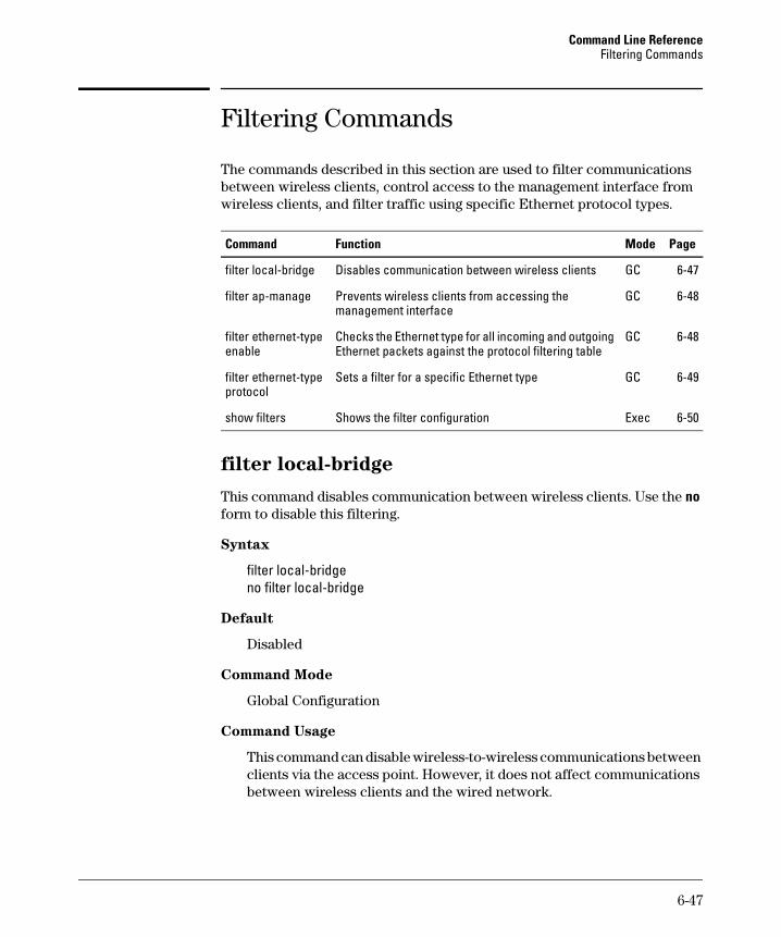
Command Line Reference Filtering Commands
Filtering Commands
The commands described in this section are used to filter communications between wireless clients, control access to the management interface from wireless clients, and filter traffic using specific Ethernet protocol types.
Command Function Mode Page
filter local-bridge
filter ap-manage
filter ethernet-type enable
filter ethernet-type protocol
show filters
Disables communication between wireless clients GC 6-47
Prevents wireless clients from accessing the GC 6-48 management interface
Checks the Ethernet type for all incoming and outgoing GC 6-48 Ethernet packets against the protocol filtering table
Sets a filter for a specific Ethernet type GC 6-49
Shows the filter configuration Exec 6-50
filter local-bridge
This command disables communication between wireless clients. Use the no form to disable this filtering.
Syntax
filter local-bridge no filter local-bridge
Default
Disabled
Command Mode
Global Configuration
Command Usage
This command can disable wireless-to-wireless communications between clients via the access point. However, it does not affect communications between wireless clients and the wired network.
6-47

Command Line Reference Filtering Commands
Example
HP420(config)#filter local-bridgeHP420(config)#
filter ap-manage
This command prevents wireless clients from accessing the management interface on the access point. Use the no form to disable this filtering.
Syntax
filter ap-manage no filter ap-manage
Default
Disabled
Command Mode
Global Configuration
Example
HP420(config)#filter ap-manageHP420(config)#
filter ethernet-type enable
This command checks the Ethernet type on all incoming and outgoing Ethernet packets against the protocol filtering table. Use the no form to disable this feature.
Syntax
filter ethernet-type enable no filter ethernet-type enable
Default
Disabled
Command Mode
Global Configuration
6-48
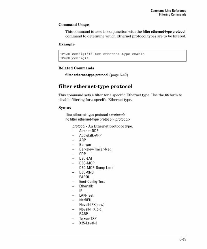
Command Line Reference Filtering Commands
Command Usage
This command is used in conjunction with the filter ethernet-type protocol command to determine which Ethernet protocol types are to be filtered.
Example
HP420(config)#filter ethernet-type enableHP420(config)#
Related Commands
filter ethernet-type protocol (page 6-49)
filter ethernet-type protocol
This command sets a filter for a specific Ethernet type. Use the no form to disable filtering for a specific Ethernet type.
Syntax
filter ethernet-type protocol <protocol> no filter ethernet-type protocol <protocol>
protocol - An Ethernet protocol type. – Aironet-DDP – Appletalk-ARP – ARP – Banyan – Berkeley-Trailer-Neg – CDP – DEC-LAT – DEC-MOP – DEC-MOP-Dump-Load – DEC-XNS – EAPOL – Enet-Config-Test – Ethertalk – IP – LAN-Test – NetBEUI – Novell-IPX(new) – Novell-IPX(old) – RARP – Telxon-TXP – X25-Level-3
6-49
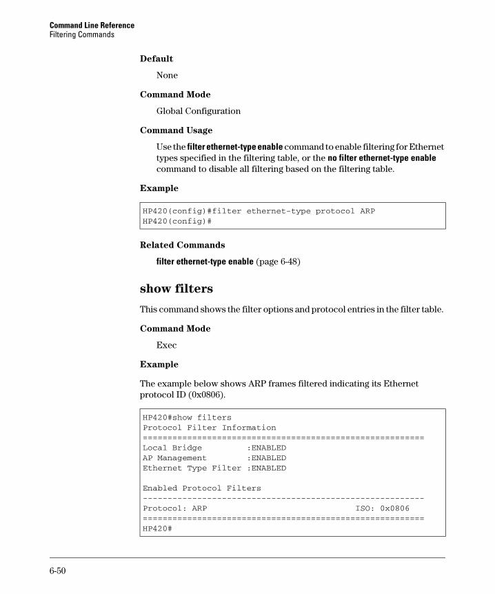
Command Line Reference Filtering Commands
---------------------------------------------------------
Default
None
Command Mode
Global Configuration
Command Usage
Use the filter ethernet-type enable command to enable filtering for Ethernet types specified in the filtering table, or the no filter ethernet-type enable command to disable all filtering based on the filtering table.
Example
HP420(config)#filter ethernet-type protocol ARPHP420(config)#
Related Commands
filter ethernet-type enable (page 6-48)
show filters
This command shows the filter options and protocol entries in the filter table.
Command Mode
Exec
Example
The example below shows ARP frames filtered indicating its Ethernet protocol ID (0x0806).
HP420#show filtersProtocol Filter Information=========================================================Local Bridge :ENABLEDAP Management :ENABLEDEthernet Type Filter :ENABLED
Enabled Protocol Filters
Protocol: ARP ISO: 0x0806=========================================================HP420#
6-50

Command Line Reference Interface Commands
Interface Commands
The commands described in this section configure connection parameters for the Ethernet interface and wireless interface.
Command Function Mode Page
General Interface
interface
Ethernet Interface
dns primary-server
dns secondary-server
ip address
ip dhcp
shutdown
speed-duplex
show interface ethernet
Wireless Interface
radio-mode
description
closed-system
speed
channel
ssid
beacon-interval
dtim-period
fragmentation-length
Enters specified interface configuration mode GC 6-53
Specifies the primary name server IC-E 6-53
Specifies the secondary name server IC-E 6-53
Sets the IP address for the Ethernet interface IC-E 6-54
Submits a DHCP request for an IP address IC-E 6-55
Disables the Ethernet interface IC-E 6-56
Configures speed and duplex operation IC-E 6-57
Shows the status for the Ethernet interface Exec 6-57
Sets the radio working mode IC-W 6-58
Adds a description to the wireless interface IC-W 6-59
Closes access to clients without a pre- IC-W 6-59 configured SSID
Configures the maximum data rate at which a IC-W 6-60 station can connect to the access point
Configures the radio channel IC-W 6-61
Configures the service set identifier IC-W 6-62
Configures the rate at which beacon signals IC-W 6-62 are transmitted from the access point
Configures the rate at which stations in sleep IC-W 6-63mode must wake up to receive broadcast/multicast transmissions
Configures the minimum packet size that can IC-W 6-64 be fragmented
6-51
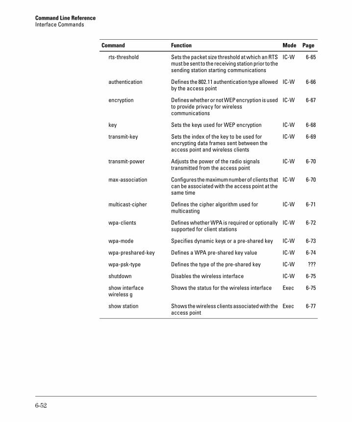
Command Line Reference Interface Commands
Command Function Mode Page
rts-threshold Sets the packet size threshold at which an RTS IC-W 6-65 must be sent to the receiving station prior to the sending station starting communications
authentication Defines the 802.11 authentication type allowed IC-W 6-66 by the access point
encryption Defines whether or not WEP encryption is used IC-W 6-67 to provide privacy for wireless communications
key Sets the keys used for WEP encryption IC-W 6-68
transmit-key Sets the index of the key to be used for IC-W 6-69 encrypting data frames sent between the access point and wireless clients
transmit-power Adjusts the power of the radio signals IC-W 6-70 transmitted from the access point
max-association Configures the maximum number of clients that IC-W 6-70 can be associated with the access point at the same time
multicast-cipher Defines the cipher algorithm used for IC-W 6-71 multicasting
wpa-clients Defines whether WPA is required or optionally IC-W 6-72 supported for client stations
wpa-mode Specifies dynamic keys or a pre-shared key IC-W 6-73
wpa-preshared-key Defines a WPA pre-shared key value IC-W 6-74
wpa-psk-type Defines the type of the pre-shared key IC-W ???
shutdown Disables the wireless interface IC-W 6-75
show interface Shows the status for the wireless interface Exec 6-75 wireless g
show station Shows the wireless clients associated with the Exec 6-77 access point
6-52
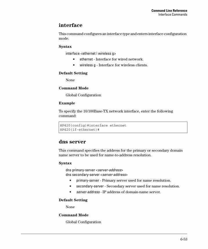
Command Line Reference Interface Commands
interface
This command configures an interface type and enters interface configuration mode.
Syntax
interface <ethernet | wireless g> • ethernet - Interface for wired network.
• wireless g - Interface for wireless clients.
Default Setting
None
Command Mode
Global Configuration
Example
To specify the 10/100Base-TX network interface, enter the following command:
HP420(config)#interface ethernet HP420(if-ethernet)#
dns server
This command specifies the address for the primary or secondary domain name server to be used for name-to-address resolution.
Syntax
dns primary-server <server-address> dns secondary-server <server-address>
• primary-server - Primary server used for name resolution.
• secondary-server - Secondary server used for name resolution.
• server-address - IP address of domain-name server.
Default Setting
None
Command Mode
Global Configuration
6-53

Command Line Reference Interface Commands
Command Usage
The primary and secondary name servers are queried in sequence.
Example
This example specifies two domain-name servers.
HP420(if-ethernet)#dns primary-server 192.168.1.55HP420(if-ethernet)#dns secondary-server 10.1.0.55HP420(if-ethernet)#
Related Commands
show interface ethernet (page 6-57)
ip address
This command sets the IP address for the (10/100Base-TX) Ethernet interface. Use the no form to restore the default IP address.
Syntax
ip address <ip-address> <netmask> <gateway> no ip address
• ip-address - IP address
• netmask - Network mask for the associated IP subnet. This mask identifies the host address bits used for routing to specific subnets.
• gateway - IP address of the default gateway
Default Setting
IP address: 192.168.1.1 Netmask: 255.255.255.0
Command Mode
Interface Configuration (Ethernet)
Command Usage
• DHCP is enabled by default. To manually configure a new IP address, you must first disable the DHCP client with the no ip dhcp command.
• You must assign an IP address to this device to gain management access over the network or to connect to existing IP subnets. You can manually configure a specific IP address using this command, or direct the device to obtain an address from a DHCP server using the
6-54
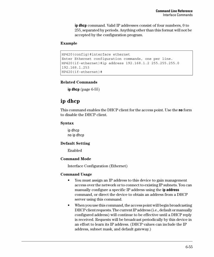
Command Line Reference Interface Commands
ip dhcp command. Valid IP addresses consist of four numbers, 0 to 255, separated by periods. Anything other than this format will not be accepted by the configuration program.
Example
HP420(config)#interface ethernetEnter Ethernet configuration commands, one per line.HP420(if-ethernet)#ip address 192.168.1.2 255.255.255.0192.168.1.253HP420(if-ethernet)#
Related Commands
ip dhcp (page 6-55)
ip dhcp
This command enables the DHCP client for the access point. Use the no form to disable the DHCP client.
Syntax
ip dhcp no ip dhcp
Default Setting
Enabled
Command Mode
Interface Configuration (Ethernet)
Command Usage
• You must assign an IP address to this device to gain management access over the network or to connect to existing IP subnets. You can manually configure a specific IP address using the ip address command, or direct the device to obtain an address from a DHCP server using this command.
• When you use this command, the access point will begin broadcasting DHCP client requests. The current IP address (i.e., default or manually configured address) will continue to be effective until a DHCP reply is received. Requests will be broadcast periodically by this device in an effort to learn its IP address. (DHCP values can include the IP address, subnet mask, and default gateway.)
6-55
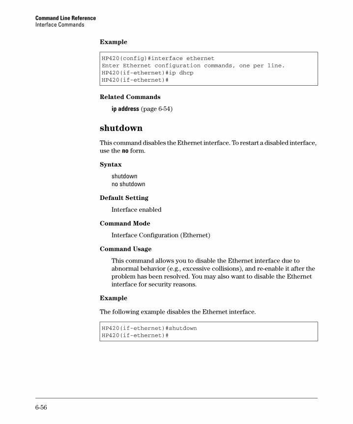
Command Line Reference Interface Commands
Example
HP420(config)#interface ethernetEnter Ethernet configuration commands, one per line.HP420(if-ethernet)#ip dhcpHP420(if-ethernet)#
Related Commands
ip address (page 6-54)
shutdown
This command disables the Ethernet interface. To restart a disabled interface, use the no form.
Syntax
shutdown no shutdown
Default Setting
Interface enabled
Command Mode
Interface Configuration (Ethernet)
Command Usage
This command allows you to disable the Ethernet interface due to abnormal behavior (e.g., excessive collisions), and re-enable it after the problem has been resolved. You may also want to disable the Ethernet interface for security reasons.
Example
The following example disables the Ethernet interface.
HP420(if-ethernet)#shutdownHP420(if-ethernet)#
6-56
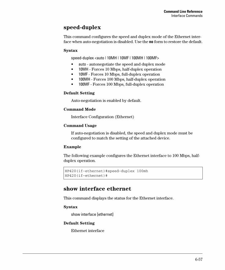
Command Line Reference Interface Commands
speed-duplex
This command configures the speed and duplex mode of the Ethernet inter-face when auto-negotiation is disabled. Use the no form to restore the default.
Syntax
speed-duplex <auto | 10MH | 10MF | 100MH | 100MF> • auto - autonegotiate the speed and duplex mode • 10MH - Forces 10 Mbps, half-duplex operation • 10MF - Forces 10 Mbps, full-duplex operation • 100MH - Forces 100 Mbps, half-duplex operation • 100MF - Forces 100 Mbps, full-duplex operation
Default Setting
Auto-negotiation is enabled by default.
Command Mode
Interface Configuration (Ethernet)
Command Usage
If auto-negotiation is disabled, the speed and duplex mode must be configured to match the setting of the attached device.
Example
The following example configures the Ethernet interface to 100 Mbps, half-duplex operation.
HP420(if-ethernet)#speed-duplex 100mhHP420(if-ethernet)#
show interface ethernet
This command displays the status for the Ethernet interface.
Syntax
show interface [ethernet]
Default Setting
Ethernet interface
6-57
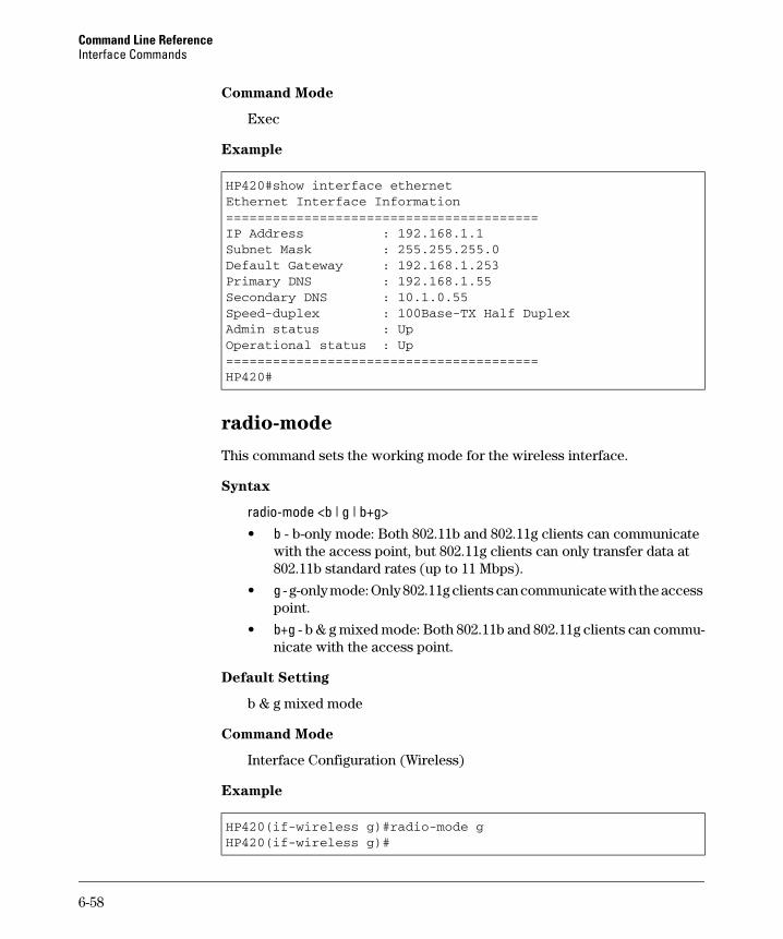
Command Line Reference Interface Commands
Command Mode
Exec
Example
HP420#show interface ethernetEthernet Interface Information========================================IP Address : 192.168.1.1Subnet Mask : 255.255.255.0Default Gateway : 192.168.1.253Primary DNS : 192.168.1.55Secondary DNS : 10.1.0.55Speed-duplex : 100Base-TX Half DuplexAdmin status : UpOperational status : Up========================================HP420#
radio-mode
This command sets the working mode for the wireless interface.
Syntax
radio-mode <b | g | b+g> • b - b-only mode: Both 802.11b and 802.11g clients can communicate
with the access point, but 802.11g clients can only transfer data at 802.11b standard rates (up to 11 Mbps).
• g - g-only mode: Only 802.11g clients can communicate with the access point.
• b+g - b & g mixed mode: Both 802.11b and 802.11g clients can communicate with the access point.
Default Setting
b & g mixed mode
Command Mode
Interface Configuration (Wireless)
Example
HP420(if-wireless g)#radio-mode gHP420(if-wireless g)#
6-58
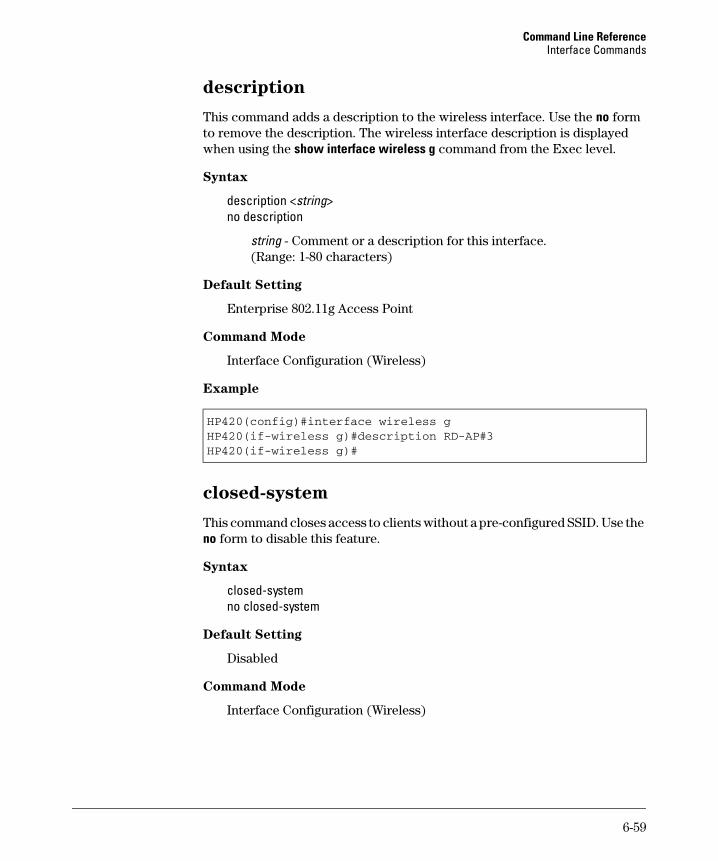
Command Line Reference Interface Commands
description
This command adds a description to the wireless interface. Use the no form to remove the description. The wireless interface description is displayed when using the show interface wireless g command from the Exec level.
Syntax
description <string> no description
string - Comment or a description for this interface. (Range: 1-80 characters)
Default Setting
Enterprise 802.11g Access Point
Command Mode
Interface Configuration (Wireless)
Example
HP420(config)#interface wireless gHP420(if-wireless g)#description RD-AP#3HP420(if-wireless g)#
closed-system
This command closes access to clients without a pre-configured SSID. Use the no form to disable this feature.
Syntax
closed-system no closed-system
Default Setting
Disabled
Command Mode
Interface Configuration (Wireless)
6-59
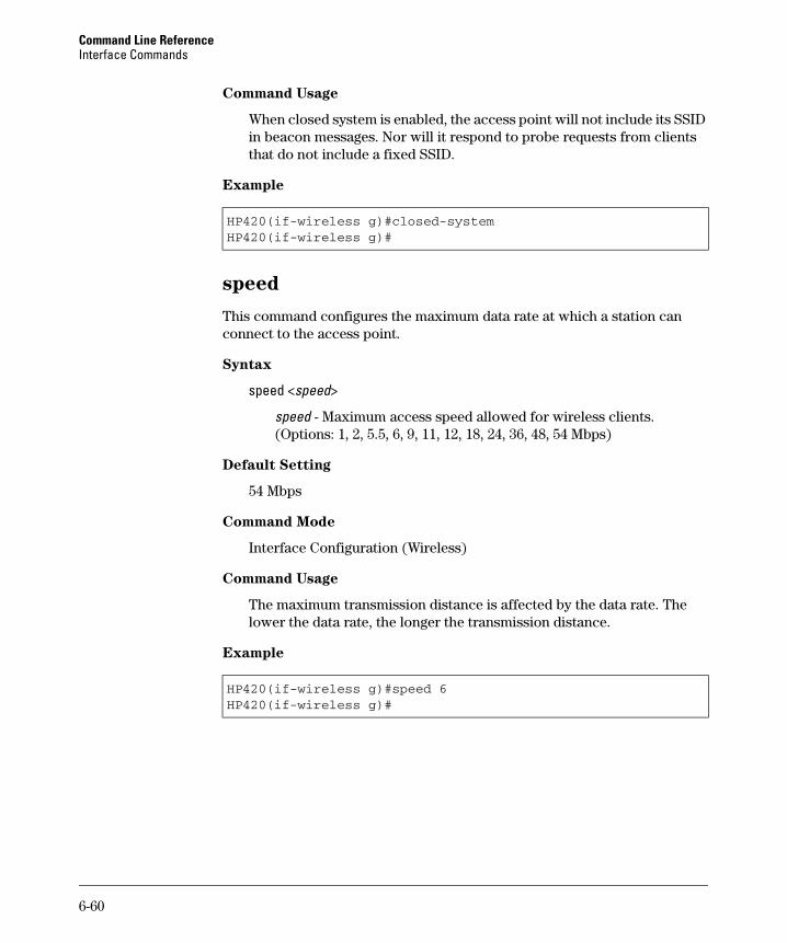
Command Line Reference Interface Commands
Command Usage
When closed system is enabled, the access point will not include its SSID in beacon messages. Nor will it respond to probe requests from clients that do not include a fixed SSID.
Example
HP420(if-wireless g)#closed-systemHP420(if-wireless g)#
speed
This command configures the maximum data rate at which a station can connect to the access point.
Syntax
speed <speed>
speed - Maximum access speed allowed for wireless clients. (Options: 1, 2, 5.5, 6, 9, 11, 12, 18, 24, 36, 48, 54 Mbps)
Default Setting
54 Mbps
Command Mode
Interface Configuration (Wireless)
Command Usage
The maximum transmission distance is affected by the data rate. The lower the data rate, the longer the transmission distance.
Example
HP420(if-wireless g)#speed 6HP420(if-wireless g)#
6-60
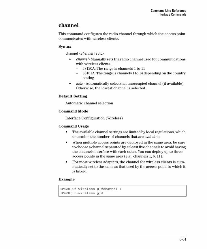
Command Line Reference Interface Commands
channel
This command configures the radio channel through which the access point communicates with wireless clients.
Syntax
channel <channel | auto> • channel - Manually sets the radio channel used for communications
with wireless clients. – J8130A: The range is channels 1 to 11 – J8131A: The range is channels 1 to 14 depending on the country
setting
• auto - Automatically selects an unoccupied channel (if available). Otherwise, the lowest channel is selected.
Default Setting
Automatic channel selection
Command Mode
Interface Configuration (Wireless)
Command Usage
• The available channel settings are limited by local regulations, which determine the number of channels that are available.
• When multiple access points are deployed in the same area, be sure to choose a channel separated by at least five channels to avoid having the channels interfere with each other. You can deploy up to three access points in the same area (e.g., channels 1, 6, 11).
• For most wireless adapters, the channel for wireless clients is automatically set to the same as that used by the access point to which it is linked.
Example
HP420(if-wireless g)#channel 1HP420(if-wireless g)#
6-61
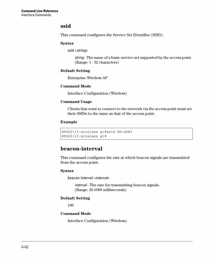
Command Line Reference Interface Commands
ssid
This command configures the Service Set IDentifier (SSID).
Syntax
ssid <string>
string - The name of a basic service set supported by the access point. (Range: 1 - 32 characters)
Default Setting
Enterprise Wireless AP
Command Mode
Interface Configuration (Wireless)
Command Usage
Clients that want to connect to the network via the access point must set their SSIDs to the same as that of the access point.
Example
HP420(if-wireless g)#ssid RD-AP#3HP420(if-wireless g)#
beacon-interval
This command configures the rate at which beacon signals are transmitted from the access point.
Syntax
beacon-interval <interval>
interval - The rate for transmitting beacon signals. (Range: 20-1000 milliseconds)
Default Setting
100
Command Mode
Interface Configuration (Wireless)
6-62
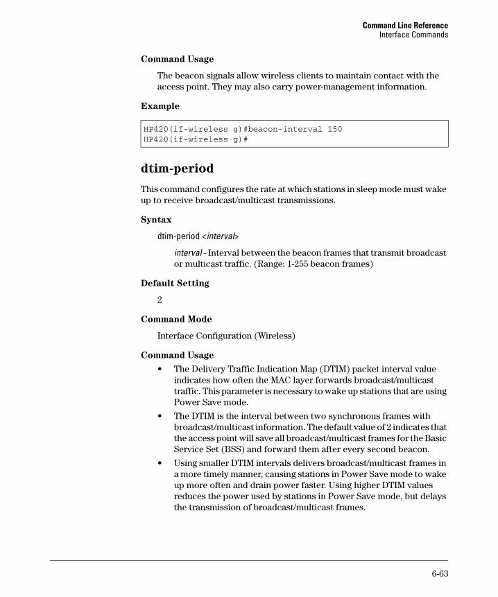
Command Line Reference Interface Commands
Command Usage
The beacon signals allow wireless clients to maintain contact with the access point. They may also carry power-management information.
Example
HP420(if-wireless g)#beacon-interval 150HP420(if-wireless g)#
dtim-period
This command configures the rate at which stations in sleep mode must wake up to receive broadcast/multicast transmissions.
Syntax
dtim-period <interval>
interval - Interval between the beacon frames that transmit broadcast or multicast traffic. (Range: 1-255 beacon frames)
Default Setting
2
Command Mode
Interface Configuration (Wireless)
Command Usage
• The Delivery Traffic Indication Map (DTIM) packet interval value indicates how often the MAC layer forwards broadcast/multicast traffic. This parameter is necessary to wake up stations that are using Power Save mode.
• The DTIM is the interval between two synchronous frames with broadcast/multicast information. The default value of 2 indicates that the access point will save all broadcast/multicast frames for the Basic Service Set (BSS) and forward them after every second beacon.
• Using smaller DTIM intervals delivers broadcast/multicast frames in a more timely manner, causing stations in Power Save mode to wake up more often and drain power faster. Using higher DTIM values reduces the power used by stations in Power Save mode, but delays the transmission of broadcast/multicast frames.
6-63
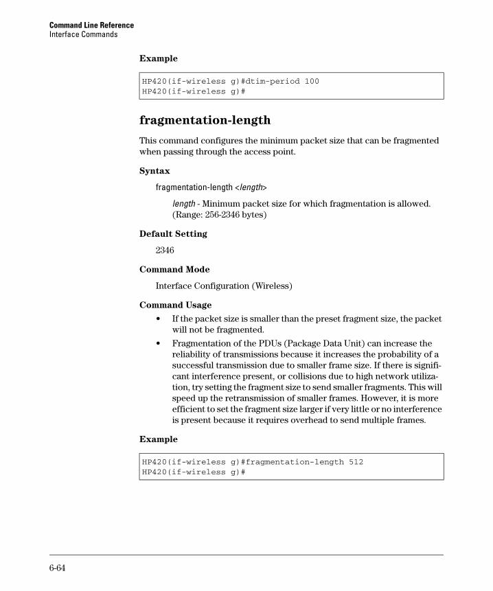
Command Line Reference Interface Commands
Example
HP420(if-wireless g)#dtim-period 100HP420(if-wireless g)#
fragmentation-length
This command configures the minimum packet size that can be fragmented when passing through the access point.
Syntax
fragmentation-length <length>
length - Minimum packet size for which fragmentation is allowed. (Range: 256-2346 bytes)
Default Setting
2346
Command Mode
Interface Configuration (Wireless)
Command Usage
• If the packet size is smaller than the preset fragment size, the packet will not be fragmented.
• Fragmentation of the PDUs (Package Data Unit) can increase the reliability of transmissions because it increases the probability of a successful transmission due to smaller frame size. If there is significant interference present, or collisions due to high network utilization, try setting the fragment size to send smaller fragments. This will speed up the retransmission of smaller frames. However, it is more efficient to set the fragment size larger if very little or no interference is present because it requires overhead to send multiple frames.
Example
HP420(if-wireless g)#fragmentation-length 512HP420(if-wireless g)#
6-64
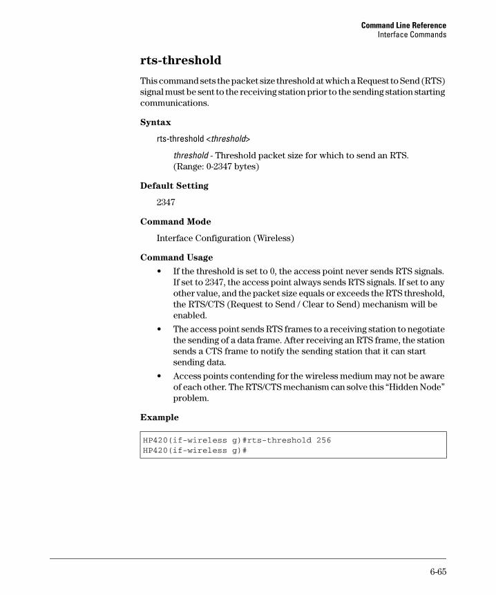
Command Line Reference Interface Commands
rts-threshold
This command sets the packet size threshold at which a Request to Send (RTS) signal must be sent to the receiving station prior to the sending station starting communications.
Syntax
rts-threshold <threshold>
threshold - Threshold packet size for which to send an RTS. (Range: 0-2347 bytes)
Default Setting
2347
Command Mode
Interface Configuration (Wireless)
Command Usage
• If the threshold is set to 0, the access point never sends RTS signals. If set to 2347, the access point always sends RTS signals. If set to any other value, and the packet size equals or exceeds the RTS threshold, the RTS/CTS (Request to Send / Clear to Send) mechanism will be enabled.
• The access point sends RTS frames to a receiving station to negotiate the sending of a data frame. After receiving an RTS frame, the station sends a CTS frame to notify the sending station that it can start sending data.
• Access points contending for the wireless medium may not be aware of each other. The RTS/CTS mechanism can solve this “Hidden Node” problem.
Example
HP420(if-wireless g)#rts-threshold 256HP420(if-wireless g)#
6-65
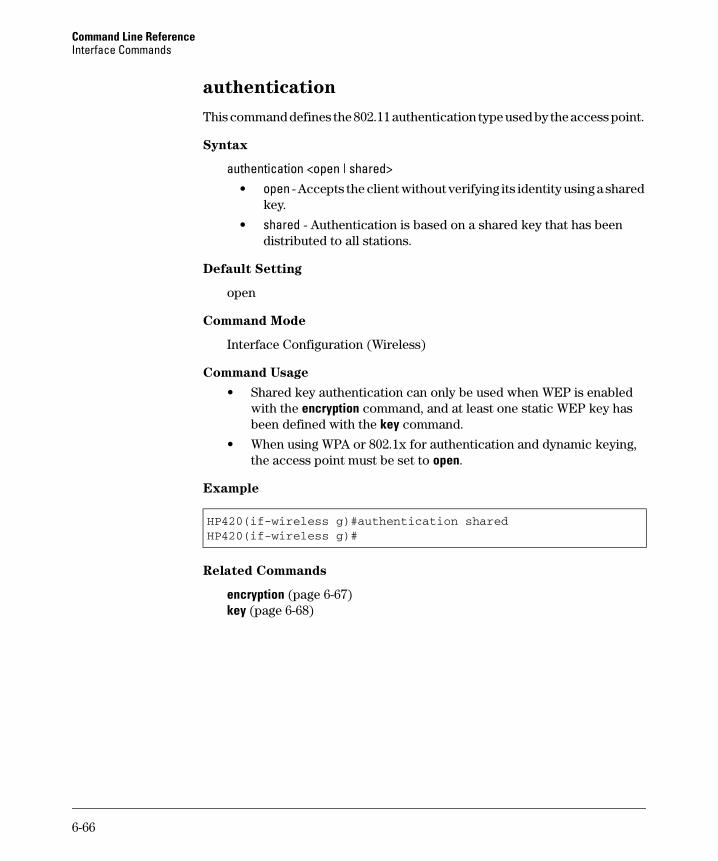
Command Line Reference Interface Commands
authentication
This command defines the 802.11 authentication type used by the access point.
Syntax
authentication <open | shared> • open - Accepts the client without verifying its identity using a shared
key.
• shared - Authentication is based on a shared key that has been distributed to all stations.
Default Setting
open
Command Mode
Interface Configuration (Wireless)
Command Usage
• Shared key authentication can only be used when WEP is enabled with the encryption command, and at least one static WEP key has been defined with the key command.
• When using WPA or 802.1x for authentication and dynamic keying, the access point must be set to open.
Example
HP420(if-wireless g)#authentication sharedHP420(if-wireless g)#
Related Commands
encryption (page 6-67) key (page 6-68)
6-66
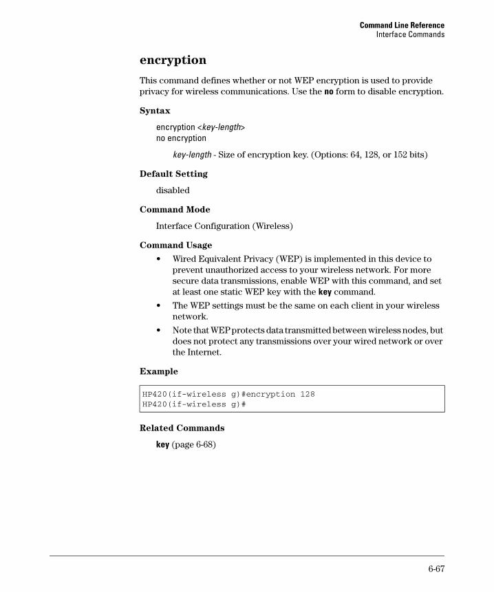
Command Line Reference Interface Commands
encryption
This command defines whether or not WEP encryption is used to provide privacy for wireless communications. Use the no form to disable encryption.
Syntax
encryption <key-length> no encryption
key-length - Size of encryption key. (Options: 64, 128, or 152 bits)
Default Setting
disabled
Command Mode
Interface Configuration (Wireless)
Command Usage
• Wired Equivalent Privacy (WEP) is implemented in this device to prevent unauthorized access to your wireless network. For more secure data transmissions, enable WEP with this command, and set at least one static WEP key with the key command.
• The WEP settings must be the same on each client in your wireless network.
• Note that WEP protects data transmitted between wireless nodes, but does not protect any transmissions over your wired network or over the Internet.
Example
HP420(if-wireless g)#encryption 128HP420(if-wireless g)#
Related Commands
key (page 6-68)
6-67
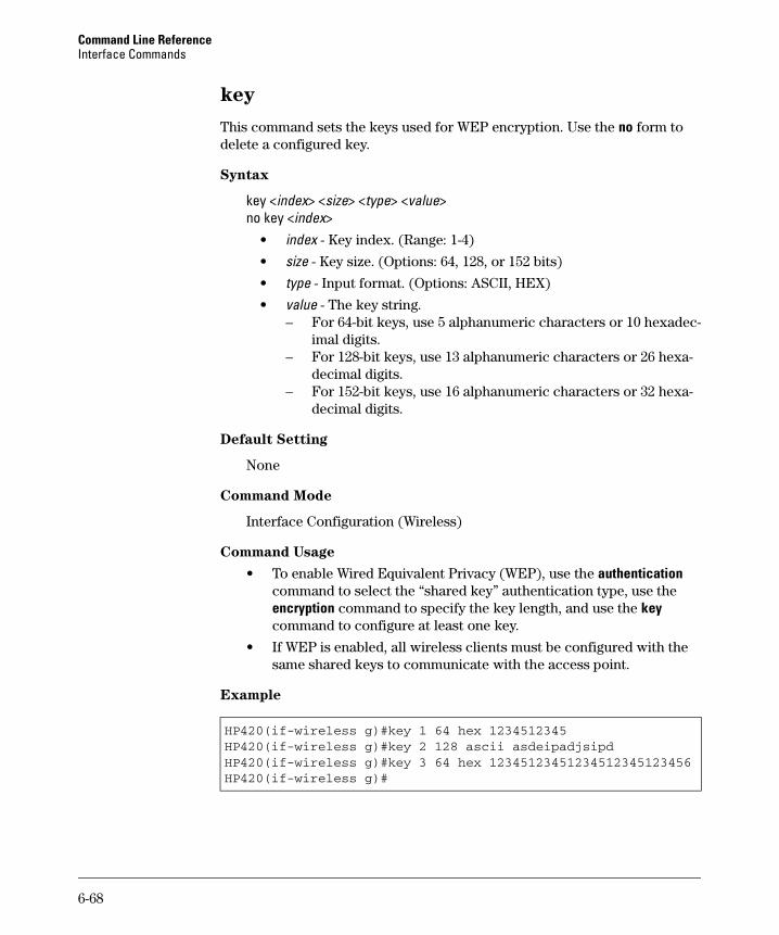
Command Line Reference Interface Commands
key
This command sets the keys used for WEP encryption. Use the no form to delete a configured key.
Syntax
key <index> <size> <type> <value> no key <index>
• index - Key index. (Range: 1-4)
• size - Key size. (Options: 64, 128, or 152 bits)
• type - Input format. (Options: ASCII, HEX)
• value - The key string. – For 64-bit keys, use 5 alphanumeric characters or 10 hexadec
imal digits. – For 128-bit keys, use 13 alphanumeric characters or 26 hexa
decimal digits. – For 152-bit keys, use 16 alphanumeric characters or 32 hexa
decimal digits.
Default Setting
None
Command Mode
Interface Configuration (Wireless)
Command Usage
• To enable Wired Equivalent Privacy (WEP), use the authentication command to select the “shared key” authentication type, use the encryption command to specify the key length, and use the key command to configure at least one key.
• If WEP is enabled, all wireless clients must be configured with the same shared keys to communicate with the access point.
Example
HP420(if-wireless g)#key 1 64 hex 1234512345HP420(if-wireless g)#key 2 128 ascii asdeipadjsipdHP420(if-wireless g)#key 3 64 hex 12345123451234512345123456HP420(if-wireless g)#
6-68
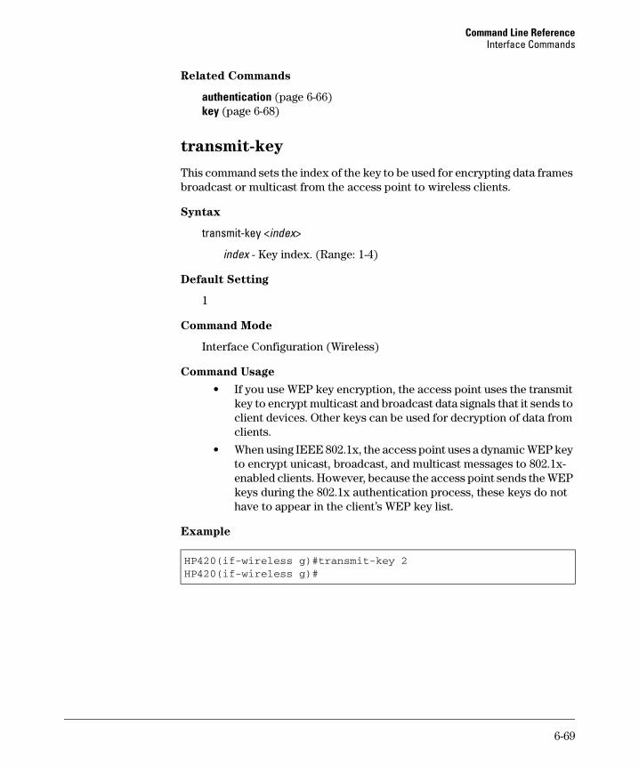
Command Line Reference Interface Commands
Related Commands
authentication (page 6-66) key (page 6-68)
transmit-key
This command sets the index of the key to be used for encrypting data frames broadcast or multicast from the access point to wireless clients.
Syntax
transmit-key <index>
index - Key index. (Range: 1-4)
Default Setting
1
Command Mode
Interface Configuration (Wireless)
Command Usage
• If you use WEP key encryption, the access point uses the transmit key to encrypt multicast and broadcast data signals that it sends to client devices. Other keys can be used for decryption of data from clients.
• When using IEEE 802.1x, the access point uses a dynamic WEP key to encrypt unicast, broadcast, and multicast messages to 802.1x-enabled clients. However, because the access point sends the WEP keys during the 802.1x authentication process, these keys do not have to appear in the client’s WEP key list.
Example
HP420(if-wireless g)#transmit-key 2HP420(if-wireless g)#
6-69
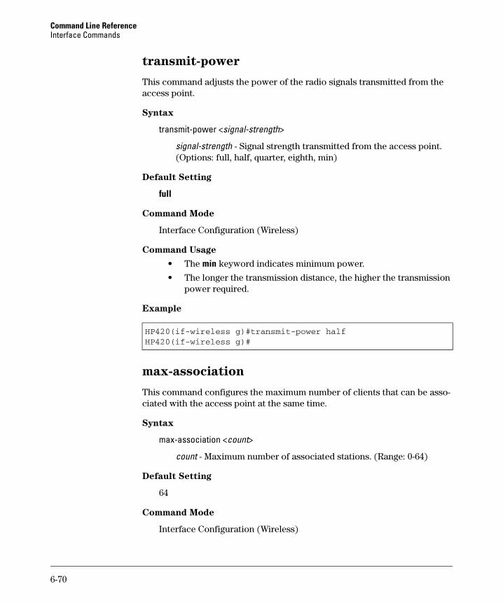
Command Line Reference Interface Commands
transmit-power
This command adjusts the power of the radio signals transmitted from the access point.
Syntax
transmit-power <signal-strength>
signal-strength - Signal strength transmitted from the access point. (Options: full, half, quarter, eighth, min)
Default Setting
full
Command Mode
Interface Configuration (Wireless)
Command Usage
• The min keyword indicates minimum power.
• The longer the transmission distance, the higher the transmission power required.
Example
HP420(if-wireless g)#transmit-power halfHP420(if-wireless g)#
max-association
This command configures the maximum number of clients that can be associated with the access point at the same time.
Syntax
max-association <count>
count - Maximum number of associated stations. (Range: 0-64)
Default Setting
64
Command Mode
Interface Configuration (Wireless)
6-70
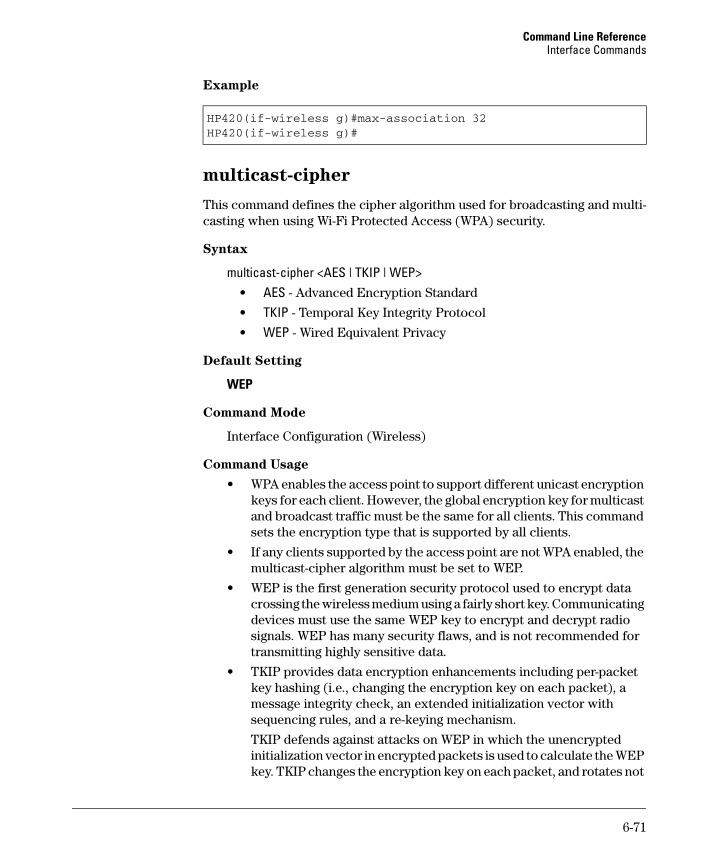
Command Line Reference Interface Commands
Example
HP420(if-wireless g)#max-association 32HP420(if-wireless g)#
multicast-cipher
This command defines the cipher algorithm used for broadcasting and multi-casting when using Wi-Fi Protected Access (WPA) security.
Syntax
multicast-cipher <AES | TKIP | WEP> • AES - Advanced Encryption Standard
• TKIP - Temporal Key Integrity Protocol
• WEP - Wired Equivalent Privacy
Default Setting
WEP
Command Mode
Interface Configuration (Wireless)
Command Usage
• WPA enables the access point to support different unicast encryption keys for each client. However, the global encryption key for multicast and broadcast traffic must be the same for all clients. This command sets the encryption type that is supported by all clients.
• If any clients supported by the access point are not WPA enabled, the multicast-cipher algorithm must be set to WEP.
• WEP is the first generation security protocol used to encrypt data crossing the wireless medium using a fairly short key. Communicating devices must use the same WEP key to encrypt and decrypt radio signals. WEP has many security flaws, and is not recommended for transmitting highly sensitive data.
• TKIP provides data encryption enhancements including per-packet key hashing (i.e., changing the encryption key on each packet), a message integrity check, an extended initialization vector with sequencing rules, and a re-keying mechanism.
TKIP defends against attacks on WEP in which the unencrypted initialization vector in encrypted packets is used to calculate the WEP key. TKIP changes the encryption key on each packet, and rotates not
6-71
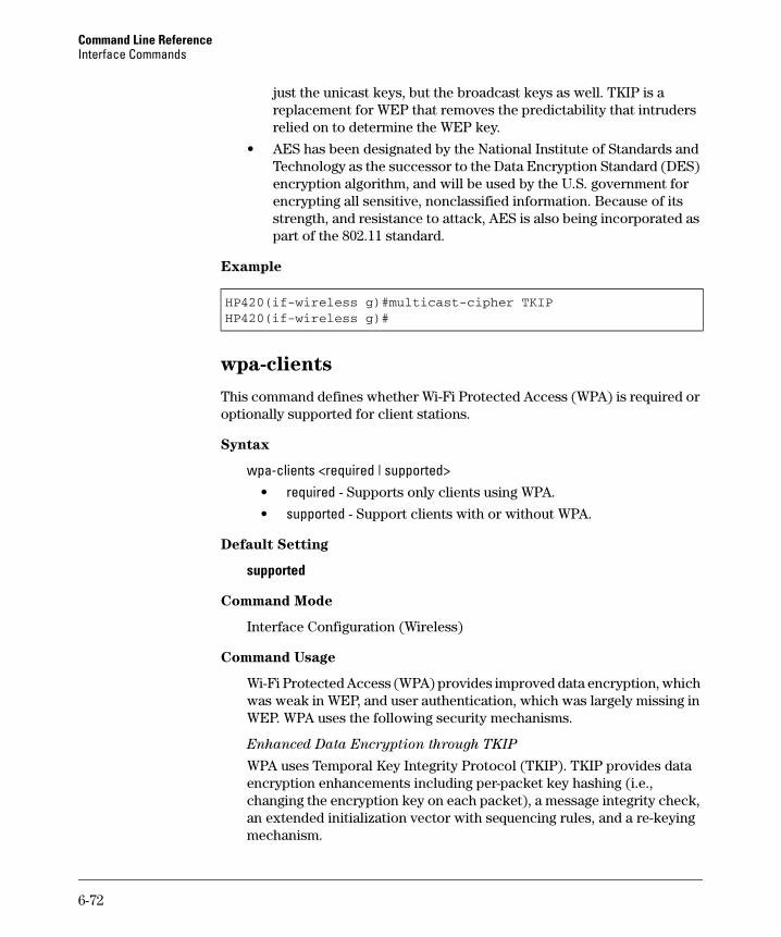
Command Line Reference Interface Commands
just the unicast keys, but the broadcast keys as well. TKIP is a replacement for WEP that removes the predictability that intruders relied on to determine the WEP key.
• AES has been designated by the National Institute of Standards and Technology as the successor to the Data Encryption Standard (DES) encryption algorithm, and will be used by the U.S. government for encrypting all sensitive, nonclassified information. Because of its strength, and resistance to attack, AES is also being incorporated as part of the 802.11 standard.
Example
HP420(if-wireless g)#multicast-cipher TKIPHP420(if-wireless g)#
wpa-clients
This command defines whether Wi-Fi Protected Access (WPA) is required or optionally supported for client stations.
Syntax
wpa-clients <required | supported> • required - Supports only clients using WPA.
• supported - Support clients with or without WPA.
Default Setting
supported
Command Mode
Interface Configuration (Wireless)
Command Usage
Wi-Fi Protected Access (WPA) provides improved data encryption, which was weak in WEP, and user authentication, which was largely missing in WEP. WPA uses the following security mechanisms.
Enhanced Data Encryption through TKIP
WPA uses Temporal Key Integrity Protocol (TKIP). TKIP provides data encryption enhancements including per-packet key hashing (i.e., changing the encryption key on each packet), a message integrity check, an extended initialization vector with sequencing rules, and a re-keying mechanism.
6-72

Command Line Reference Interface Commands
Enterprise-level User Authentication via 802.1x and EAP
To strengthen user authentication, WPA uses 802.1x and the Extensible Authentication Protocol (EAP). Used together, these protocols provide strong user authentication via a central RADIUS authentication server that authenticates each user on the network before they join it. WPA also employs “mutual authentication” to prevent a wireless client from accidentally joining a rogue network.
Example
HP420(if-wireless g)#wpa-client requiredHP420(if-wireless g)#
Related Commands
wpa-mode (page 6-73)
wpa-mode
This command specifies whether Wi-Fi Protected Access (WPA) is to use 802.1x authentication and dynamic keying or a pre-shared key.
Syntax
wpa-mode <dynamic | pre-shared-key> • dynamic - WPA with 802.1x authentication and dynamic keys.
• pre-shared-key - WPA with a pre-shared key.
Default Setting
dynamic
Command Mode
Interface Configuration (Wireless)
Command Usage
• When the WPA mode is set to dynamic, clients are authenticated using 802.1x via a RADIUS server. Each client has to be WPA-enabled or support 802.1x client software. A RADIUS server must also be configured and be available in the wired network.
• In the dynamic mode, keys are generated for each wireless client associating with the access point. These keys are regenerated periodically, and also each time the wireless client is re-authenticated.
6-73
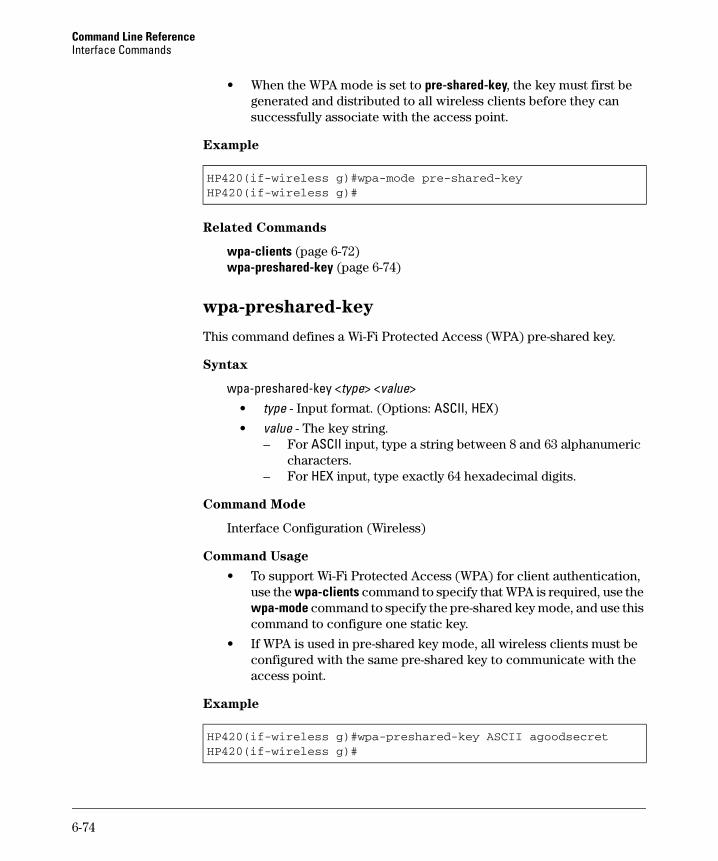
Command Line Reference Interface Commands
• When the WPA mode is set to pre-shared-key, the key must first be generated and distributed to all wireless clients before they can successfully associate with the access point.
Example
HP420(if-wireless g)#wpa-mode pre-shared-keyHP420(if-wireless g)#
Related Commands
wpa-clients (page 6-72) wpa-preshared-key (page 6-74)
wpa-preshared-key
This command defines a Wi-Fi Protected Access (WPA) pre-shared key.
Syntax
wpa-preshared-key <type> <value> • type - Input format. (Options: ASCII, HEX)
• value - The key string. – For ASCII input, type a string between 8 and 63 alphanumeric
characters. – For HEX input, type exactly 64 hexadecimal digits.
Command Mode
Interface Configuration (Wireless)
Command Usage
• To support Wi-Fi Protected Access (WPA) for client authentication, use the wpa-clients command to specify that WPA is required, use the wpa-mode command to specify the pre-shared key mode, and use this command to configure one static key.
• If WPA is used in pre-shared key mode, all wireless clients must be configured with the same pre-shared key to communicate with the access point.
Example
HP420(if-wireless g)#wpa-preshared-key ASCII agoodsecretHP420(if-wireless g)#
6-74
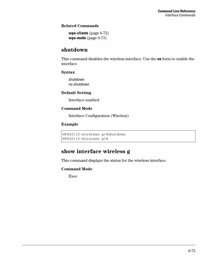
Command Line Reference Interface Commands
Related Commands
wpa-clients (page 6-72) wpa-mode (page 6-73)
shutdown
This command disables the wireless interface. Use the no form to enable the interface.
Syntax
shutdown no shutdown
Default Setting
Interface enabled
Command Mode
Interface Configuration (Wireless)
Example
HP420(if-wireless g)#shutdownHP420(if-wireless g)#
show interface wireless g
This command displays the status for the wireless interface.
Command Mode
Exec
6-75
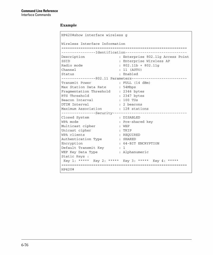
Command Line Reference Interface Commands
Example
HP420#show interface wireless g
Wireless Interface Information===========================================================----------------Identification-----------------------------Description : Enterprise 802.11g Access PointSSID : Enterprise Wireless APRadio mode : 802.11b + 802.11gChannel : 11 (AUTO)Status : Enabled----------------802.11 Parameters--------------------------Transmit Power : FULL (14 dBm)Max Station Data Rate : 54MbpsFragmentation Threshold : 2346 bytesRTS Threshold : 2347 bytesBeacon Interval : 100 TUsDTIM Interval : 2 beaconsMaximum Association : 128 stations----------------Security-----------------------------------Closed System : DISABLEDWPA mode : Pre-shared keyMulticast cipher : WEPUnicast cipher : TKIPWPA clients : REQUIREDAuthentication Type : SHAREDEncryption : 64-BIT ENCRYPTIONDefault Transmit Key : 1WEP Key Data Type : AlphanumericStatic Keys :Key 1: ***** Key 2: ***** Key 3: ***** Key 4: *****
===========================================================HP420#
6-76
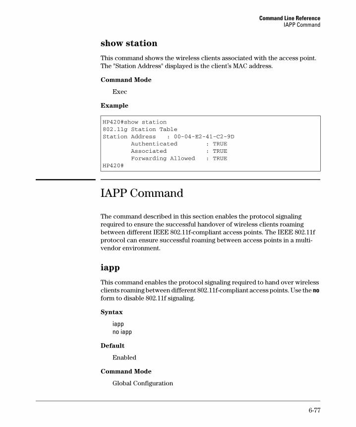
Command Line Reference IAPP Command
show station
This command shows the wireless clients associated with the access point. The "Station Address" displayed is the client’s MAC address.
Command Mode
Exec
Example
HP420#show station802.11g Station TableStation Address : 00-04-E2-41-C2-9D
Authenticated : TRUEAssociated : TRUEForwarding Allowed : TRUE
HP420#
IAPP Command
The command described in this section enables the protocol signaling required to ensure the successful handover of wireless clients roaming between different IEEE 802.11f-compliant access points. The IEEE 802.11f protocol can ensure successful roaming between access points in a multi-vendor environment.
iapp
This command enables the protocol signaling required to hand over wireless clients roaming between different 802.11f-compliant access points. Use the no form to disable 802.11f signaling.
Syntax
iapp no iapp
Default
Enabled
Command Mode
Global Configuration
6-77
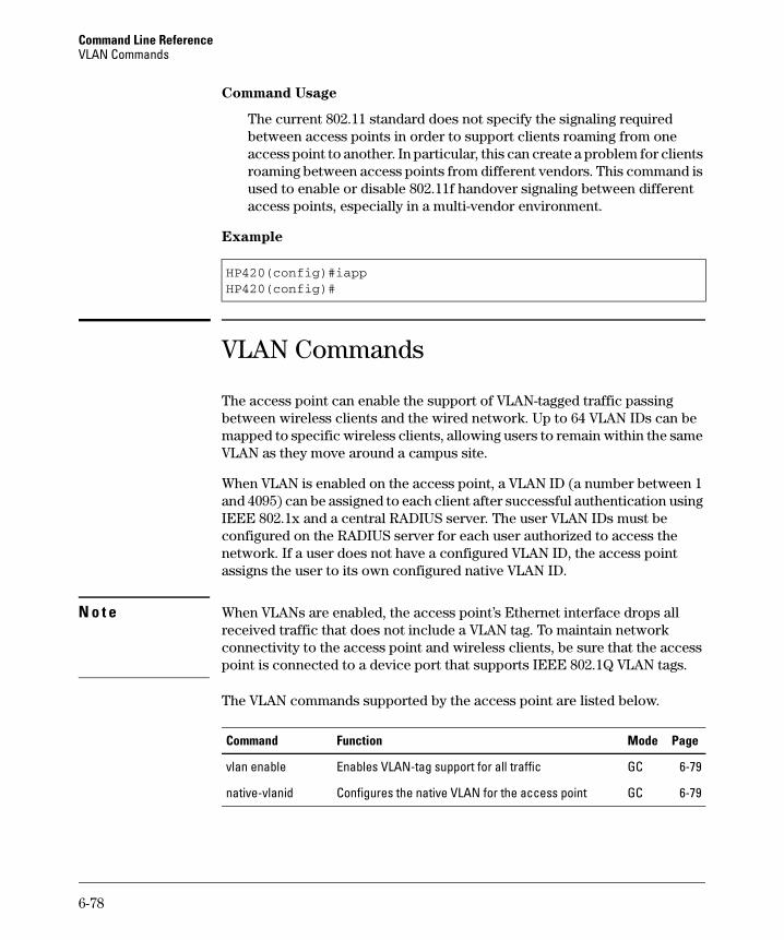
Command Line Reference VLAN Commands
Command Usage
The current 802.11 standard does not specify the signaling required between access points in order to support clients roaming from one access point to another. In particular, this can create a problem for clients roaming between access points from different vendors. This command is used to enable or disable 802.11f handover signaling between different access points, especially in a multi-vendor environment.
Example
HP420(config)#iappHP420(config)#
VLAN Commands
The access point can enable the support of VLAN-tagged traffic passing between wireless clients and the wired network. Up to 64 VLAN IDs can be mapped to specific wireless clients, allowing users to remain within the same VLAN as they move around a campus site.
When VLAN is enabled on the access point, a VLAN ID (a number between 1 and 4095) can be assigned to each client after successful authentication using IEEE 802.1x and a central RADIUS server. The user VLAN IDs must be configured on the RADIUS server for each user authorized to access the network. If a user does not have a configured VLAN ID, the access point assigns the user to its own configured native VLAN ID.
N o t e When VLANs are enabled, the access point’s Ethernet interface drops all received traffic that does not include a VLAN tag. To maintain network connectivity to the access point and wireless clients, be sure that the access point is connected to a device port that supports IEEE 802.1Q VLAN tags.
The VLAN commands supported by the access point are listed below.
Command Function Mode Page
vlan enable Enables VLAN-tag support for all traffic GC 6-79
native-vlanid Configures the native VLAN for the access point GC 6-79
6-78
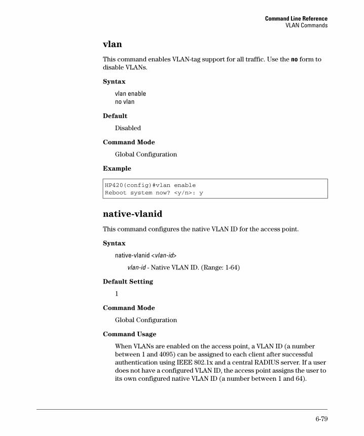
Command Line Reference VLAN Commands
vlan
This command enables VLAN-tag support for all traffic. Use the no form to disable VLANs.
Syntax
vlan enable no vlan
Default
Disabled
Command Mode
Global Configuration
Example
HP420(config)#vlan enableReboot system now? <y/n>: y
native-vlanid
This command configures the native VLAN ID for the access point.
Syntax
native-vlanid <vlan-id>
vlan-id - Native VLAN ID. (Range: 1-64)
Default Setting
1
Command Mode
Global Configuration
Command Usage
When VLANs are enabled on the access point, a VLAN ID (a number between 1 and 4095) can be assigned to each client after successful authentication using IEEE 802.1x and a central RADIUS server. If a user does not have a configured VLAN ID, the access point assigns the user to its own configured native VLAN ID (a number between 1 and 64).
6-79

Command Line Reference VLAN Commands
Example
HP420(config)#native-vlanid 3HP420(config)#
6-80

A
File Transfers
Contents
Overview . . . . . . . . . . . . . . . . . . . . . . . . . . . . . . . . . . . . . . . . . . . . . . . . . . . . A-2
Downloading Access Point Software . . . . . . . . . . . . . . . . . . . . . . . . . . . A-3
General Switch Software Download Rules . . . . . . . . . . . . . . . . . . . . . A-3
Using TFTP or FTP To Download Software from a Server . . . . . . . . A-3Web: TFTP/FTP Software Download to the Access Point . . . . . A-4CLI: TFTP/FTP Software Download to the Access Point . . . . . . A-6
Using the Web Interface To Download Software From the LocalComputer . . . . . . . . . . . . . . . . . . . . . . . . . . . . . . . . . . . . . . . . . . . . . . . . . A-6
Transferring Configuration Files . . . . . . . . . . . . . . . . . . . . . . . . . . . . . . A-8
A-1
File Transfers Overview
Overview You can download new access point software and upload or download con-figuration files. These features are useful for acquiring periodic access point software upgrades and for storing or retrieving a switch configuration.
This appendix includes the following information:
■ Downloading access point software (page A-3)
■ Transferring access point configurations (page A-8)
A-2
File Transfers Downloading Access Point Software
Downloading Access Point Software HP periodically provides access point software updates through the HP ProCurve website (http://www.hp.com/go/hpprocurve). For more information, see the support and warranty booklet shipped with the access point. After you acquire a new access point software file, you can use one of the following methods for downloading the software code to the access point.
General Switch Software Download Rules
After an access point software download, you must reboot the access point to implement the newly downloaded code. Until a reboot occurs, the access point continues to run on the software it was using before the download started.
N o t e Downloading new software does not change the current access point configuration. The access point configuration is contained in separate files that can also be transferred.
The access point stores two software files in its flash memory. One has a file name such as hp420-2022.bin, which is the current version of software the access point runs. The current software file is overwritten when new code is downloaded to the access point. The other software file, called dflt-img.bin, contains a default version of the access point code that is used if the current software file is deleted or fails. The dflt-img.bin file cannot be deleted from the system or overwritten.
Using TFTP or FTP To Download Software from a Server
This procedure assumes that:
■ A software file for the access point has been stored on a TFTP or FTP server accessible to the access point. (The access point software file is typically available from the HP ProCurve website at http://www.hp.com/go/ hpprocurve.)
■ The access point is properly connected to your network and has already been configured with a compatible IP address and subnet mask.
■ The TFTP or FTP server is accessible to the access point through IP.
A-3
File Transfers Downloading Access Point Software
Before you use the procedure, do the following:
■ Obtain the IP address of the TFTP or FTP server on which the access point software file has been stored.
■ If VLANs are configured on the access point, determine the name of the VLAN in which the TFTP or FTP server is operating.
■ Determine the name of the access point software file stored in the TFTP or FTP server for the access point (for example, hp420-2022.bin).
N o t e If your TFTP or FTP server is a Unix workstation, ensure that the case (upper
or lower) that you specify for the filename is the same case as the characters
in the access point software filenames on the server.
Web: TFTP/FTP Software Download to the Access Point
The Software Upgrade window on the Administration tab enables the access point’s system firmware to be upgraded by downloading a new file to the access point’s flash memory. The new code file must be stored remotely on an FTP or TFTP server.
N o t e Due to the size limit of the flash memory, the access point can store only two software code files.
The web interface enables you to modify these parameters:
■ Software Upgrade Remote: Downloads an operation code image file from a specified remote FTP or TFTP server. The success of the file transfer depends on the accessibility of the FTP or TFTP server and the quality of the network connection.
• New software file: Specifies the name of the code file on the server.
The new software file name should not contain slashes (\ or /), the leading letter of the file name should not be a period (.), and the maximum length for file names on the FTP/TFTP server is 255 characters or 32 characters for files on the access point. (Valid characters: A-Z, a-z, 0-9, “.”, “-”, “_”)
• IP Address: The IP address or host name of the FTP or TFTP server.
• Username: The user ID used for login on an FTP server.
• Password: The password used for login on an FTP server.
■ Restore Factory Settings: Click the Restore button to reset the access point’s configuration settings to the factory defaults and reboot the system.
■ Reset Access Point: Click the Reset button to reboot the system.
A-4
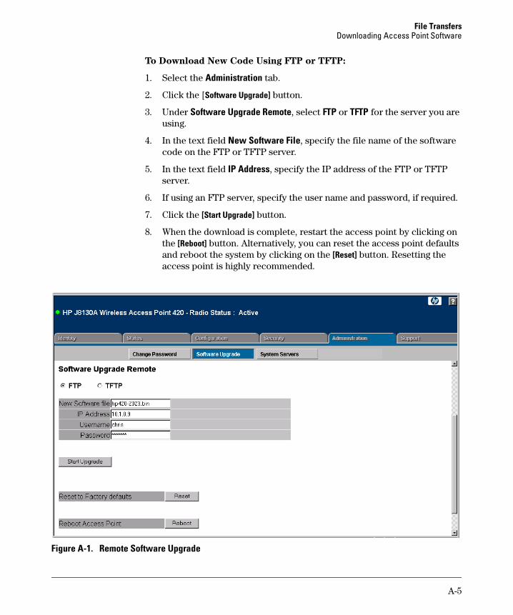
File Transfers Downloading Access Point Software
To Download New Code Using FTP or TFTP:
1. Select the Administration tab.
2. Click the [Software Upgrade] button.
3. Under Software Upgrade Remote, select FTP or TFTP for the server you are using.
4. In the text field New Software File, specify the file name of the software code on the FTP or TFTP server.
5. In the text field IP Address, specify the IP address of the FTP or TFTP server.
6. If using an FTP server, specify the user name and password, if required.
7. Click the [Start Upgrade] button.
8. When the download is complete, restart the access point by clicking on the [Reboot] button. Alternatively, you can reset the access point defaults and reboot the system by clicking on the [Reset] button. Resetting the access point is highly recommended.
Figure A-1. Remote Software Upgrade
A-5
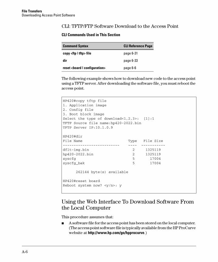
File Transfers Downloading Access Point Software
-------------------------- ---------------
CLI: TFTP/FTP Software Download to the Access Point
CLI Commands Used in This Section
Command Syntax CLI Reference Page
copy <ftp | tftp> file page 6-31
dir page 6-33
reset <board | configuration> page 6-6
The following example shows how to download new code to the access point using a TFTP server. After downloading the software file, you must reboot the access point.
HP420#copy tftp file1. Application image2. Config file3. Boot block imageSelect the type of download<1,2,3>: [1]:1TFTP Source file name:hp420-2022.binTFTP Server IP:10.1.0.9
HP420#dirFile Name Type File Size
dflt-img.bin 2 1325119hp420-2022.bin 2 1325119syscfg 5 17004syscfg_bak 5 17004
262144 byte(s) available
HP420#reset boardReboot system now? <y/n>: y
Using the Web Interface To Download Software From the Local Computer
This procedure assumes that:
■ A software file for the access point has been stored on the local computer. (The access point software file is typically available from the HP ProCurve website at http://www.hp.com/go/hpprocurve.)
A-6
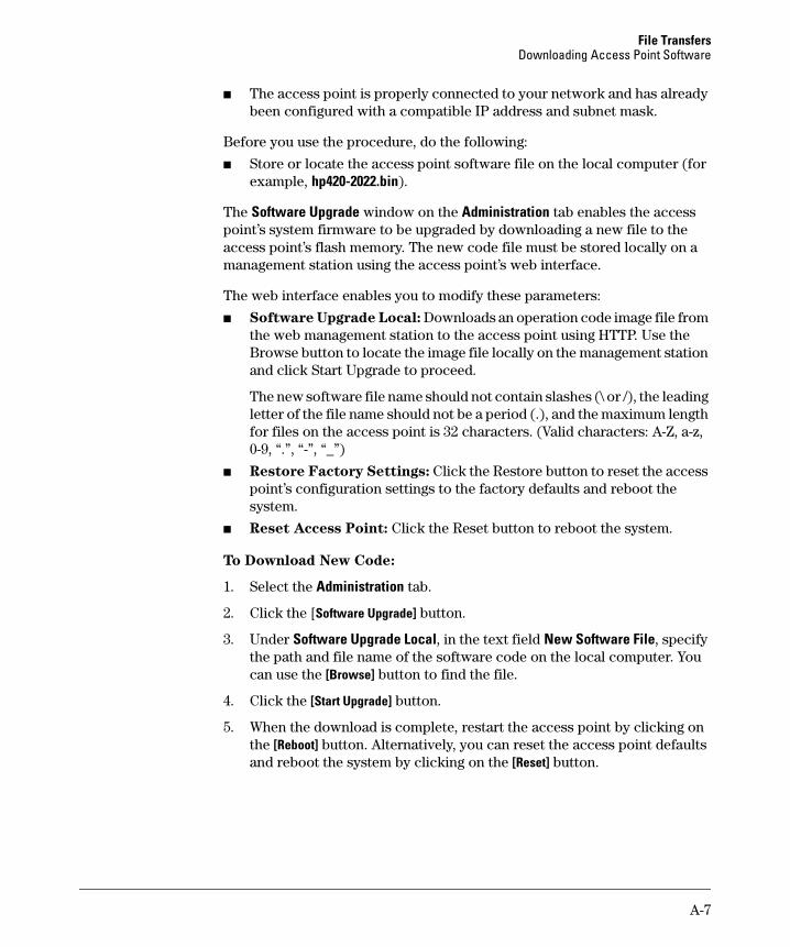
File Transfers Downloading Access Point Software
■ The access point is properly connected to your network and has already been configured with a compatible IP address and subnet mask.
Before you use the procedure, do the following:
■ Store or locate the access point software file on the local computer (for example, hp420-2022.bin).
The Software Upgrade window on the Administration tab enables the access point’s system firmware to be upgraded by downloading a new file to the access point’s flash memory. The new code file must be stored locally on a management station using the access point’s web interface.
The web interface enables you to modify these parameters:
■ Software Upgrade Local: Downloads an operation code image file from the web management station to the access point using HTTP. Use the Browse button to locate the image file locally on the management station and click Start Upgrade to proceed.
The new software file name should not contain slashes (\ or /), the leading letter of the file name should not be a period (.), and the maximum length for files on the access point is 32 characters. (Valid characters: A-Z, a-z, 0-9, “.”, “-”, “_”)
■ Restore Factory Settings: Click the Restore button to reset the access point’s configuration settings to the factory defaults and reboot the system.
■ Reset Access Point: Click the Reset button to reboot the system.
To Download New Code:
1. Select the Administration tab.
2. Click the [Software Upgrade] button.
3. Under Software Upgrade Local, in the text field New Software File, specify the path and file name of the software code on the local computer. You can use the [Browse] button to find the file.
4. Click the [Start Upgrade] button.
5. When the download is complete, restart the access point by clicking on the [Reboot] button. Alternatively, you can reset the access point defaults and reboot the system by clicking on the [Reset] button.
A-7
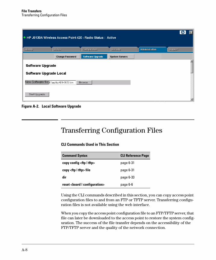
File Transfers Transferring Configuration Files
Figure A-2. Local Software Upgrade
Transferring Configuration Files
CLI Commands Used in This Section
Command Syntax CLI Reference Page
copy config <ftp | tftp> page 6-31
copy <ftp | tftp> file page 6-31
dir page 6-33
reset <board | configuration> page 6-6
Using the CLI commands described in this section, you can copy access point configuration files to and from an FTP or TFTP server. Transferring configuration files is not available using the web interface.
When you copy the access point configuration file to an FTP/TFTP server, that file can later be downloaded to the access point to restore the system configuration. The success of the file transfer depends on the accessibility of the FTP/TFTP server and the quality of the network connection.
A-8
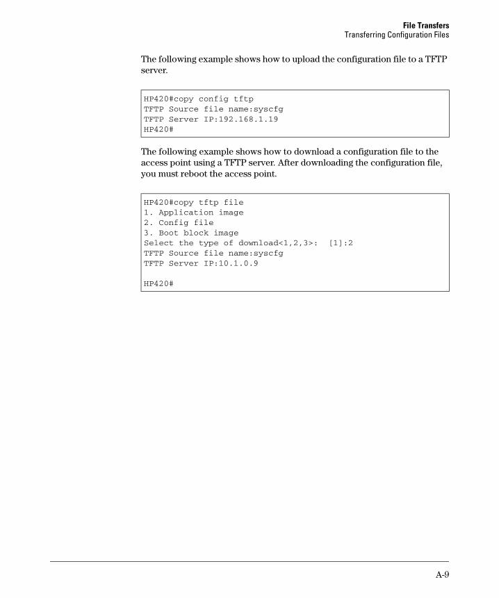
File Transfers Transferring Configuration Files
The following example shows how to upload the configuration file to a TFTP server.
HP420#copy config tftpTFTP Source file name:syscfgTFTP Server IP:192.168.1.19HP420#
The following example shows how to download a configuration file to the access point using a TFTP server. After downloading the configuration file, you must reboot the access point.
HP420#copy tftp file1. Application image2. Config file3. Boot block imageSelect the type of download<1,2,3>: [1]:2TFTP Source file name:syscfgTFTP Server IP:10.1.0.9
HP420#
A-9

File Transfers Transferring Configuration Files
A-10

Index
Numerics
802.1x authentication … 5-45, 6-39
A
address filtering … 5-46Advanced Encryption Standard … 5-47AES … 5-47authentication using MAC addresses … 5-53
B
beacon interval … 5-38
Change Password Window … 4-7cipher algorithms … 6-71closed system … 6-59community string … 6-25Complementary Code Keying … 5-37configuration
download … A-3configuration settings, saving or restoring … 6-31Country Code, setting … 5-41
D
DHCP … 5-11, 6-54, 6-55DNS name … 4-4Domain Name Server … 4-4download, TFTP … A-3downloading software … 6-31DTIM … 5-38
F
firmwaredisplaying version … 6-24upgrading … 6-31
frame filtering … 5-32
H
hardware version, displaying … 6-24HP web browser interface … 2-4
I
IAPP … 6-77IEEE 802.11f … 6-77IEEE 802.1x … 6-39IP
DHCP … 5-9using for web browser interface … 4-4
IP addressDHCP … 6-54, 6-55setting … 6-54, 6-55
L
loggingto syslog servers … 6-15
logon authenticationRADIUS client … 6-34RADIUS server … 6-34
lost password … 4-9
M
management interfaces described … 2-2
management filter … 6-47manager password … 4-8
N
network access control … 5-45
O
Open System … 5-61operator password … 4-8Orthogonal Frequency Division Multiplexing … 5-37OS download
using TFTP … A-3
C
Index – 1

P
password … 4-7, 4-8 administrator setting … 6-12 creating … 4-7 delete … 4-9 if you lose the password … 4-9 lost … 4-9 setting … 4-7
port status … 4-18 utilization … 4-18
port authentication … 6-39 ports
duplex mode … 6-57 speed … 6-57
pre-shared key, WPA … 5-47
Q
quick start … 1-6
R
radio channel selection … 5-38RADIUS server setup … 5-28RADIUS, logon authentication … 6-34Reset button … 4-9restarting the system … 6-6roaming … 6-77RTS threshold … 5-39
S
security 802.1x … 5-45 MAC filtering … 5-46 of access point … 4-9 WEP … 5-45 wireless … 5-45 WPA … 5-46
serial port configuring … 6-8
Service Set Identification … 5-5 setup screen … 1-6 shared keys, WEP … 5-63 Simple Network Time Protocol … 5-21 SNMP
community string … 6-25
enabling traps … 6-27 trap manager … 6-28
SNTP … 5-21 software
displaying version … 6-24 downloading … 6-31
SSID … 5-5 startup files
creating … 6-31 setting … 6-31
status, port … 4-18 switch software
See OS. Syslog logging … 5-17 system software, downloading from server … 6-31
T
TFTP OS download … A-3
time zone, setting … 5-21 TKIP encryption … 5-46 transmit power … 5-38 trap manager … 6-28
U
upgrading software … 6-31user name, using for browser or console
access … 4-7 user password … 6-12, 6-13 utilization, port … 4-18
V
VLAN OS download … A-4
VLAN tag support … 6-78
W
web agent enabled … 4-7 web agent,
advantages … 2-4 web browser interface
access parameters … 4-7 disable access … 4-7 enabling … 4-4
2 – Index

features … 2-4first-time tasks … 4-7main screen … 4-5, 4-17, 4-19, 4-20overview … 4-5, 4-17, 4-19, 4-20Overview window … 4-5, 4-17, 4-19, 4-20password lost … 4-9password, setting … 4-7screen elements … 4-5, 4-17security … 4-7standalone … 4-4status bar … 4-21system requirements … 4-4
WEP … 5-45Wi-Fi Protected Access … 5-46Wired Equivalent Privacy … 5-45working mode, setting … 5-37, 6-58
Index – 3