Embed Size (px)
Citation preview
HP Virtual Connect for the Cisco Network Administrator
“A technical discussion of the HP Virtual Connect 1.2x features and their interoperation with a Cisco network infrastructure”
Table of Contents
Abstract..................................................................................................................................................................3 Disclaimer, Prerequisites, and Versioning.........................................................................................................3 Introduction...........................................................................................................................................................3 Definitions...............................................................................................................................................................4 HP BladeSystem Architecture Overview ..........................................................................................................5
c-Class Cabling Layout ...................................................................................................................................6 c-Class Ethernet Interconnect Options ........................................................................................................8
HP Virtual Connect Technology ........................................................................................................................8 Overview............................................................................................................................................................8 Virtual Connect Components .......................................................................................................................9 Virtual Connect Technical Specifications .................................................................................................10 Virtual Connect Manager User Interfaces.................................................................................................10 Virtual Connect Port Descriptions ...............................................................................................................11 Overview of Virtual Connect Ethernet Connectivity...............................................................................11
VC Uplink Fault Tolerance ........................................................................................................................12 VC Uplink Load Balancing........................................................................................................................14 Port Channeling (802.3ad) Load Balancing Algorithm………………….………………………… …15
VC Uplinks and VLAN Trunking.................................................................................................................17 Unsupported Cisco VLAN Protocols.........................................…………………………………………19
Virtual Connect and NIC Teaming .............................................................................................................19 Virtual Connect and Cisco Terminology Comparison ............................................................................20 Cisco Configuration Guidelines for VC Uplink Ports.................................................................................21 Sample Virtual Connect Ethernet and Cisco Configurations ................................................................22
Sample Configuration 1: VC Uplinks Connected to Cisco Access Ports .........................................22 Sample Configuration 2: VC Uplinks Connected to Cisco VLAN Trunk Ports ..................................23 Sample Configuration 3: VC Uplinks Connected to a Cisco EtherChannel ...................................24 Sample Configuration 4: VC Uplinks Connected to a Cisco EtherChannel VLAN Trunk ..............26
Advanced Virtual Connect Ethernet Designs...........................................................................................27 Advanced VC-Enet Designs: Example Design #1 ...............................................................................28 Advanced VC-Enet Designs: Example Design #2 ...............................................................................28 Advanced VC-Enet Designs: Example Design #3 ...............................................................................29 Advanced VC-Enet Designs: Example Design #4 ...............................................................................30
Comparing VC and VMware Networking Technology...........................................................................32 Virtual Connect’s Loop Prevention Technology.......................................................................................35 Stacking Virtual Connect Ethernet Modules .............................................................................................35
Optimizing Virtual Connect Stacking Links ............................................................................................36 VC Managed MAC Addresses ....................................................................................................................37
Spanning Tree .....................................................................................................................................................38 PortFast.............................................................................................................................................................39 BPDU Guard ....................................................................................................................................................39 Unidirectional Link Detection (UDLD)..........................................................................................................39
Quality of Service ...............................................................................................................................................40 Security.................................................................................................................................................................40
ACLs & VLAN ACLs.........................................................................................................................................40 Port Security.....................................................................................................................................................41 Private VLANs..................................................................................................................................................42
Multicast & IGMP Snooping..............................................................................................................................43 SPAN (Port Monitoring) ......................................................................................................................................43 Logging ................................................................................................................................................................44 Centralized User Access Control (LDAP)........................................................................................................44 Cisco Discovery Protocol (CDP) ......................................................................................................................44 Additional Resources.........................................................................................................................................45 About the Author ...............................................................................................................................................45 Appendixes .........................................................................................................................................................46
Appendix A: Description of VC Network Diagram...................................................................................46 Appendix B: c3000 Port Mapping Diagram ..............................................................................................47 Appendix C: Frequently Asked Questions .................................................................................................48
HP Virtual Connect for Cisco Network Administrators (version 1.2x) page 3
Abstract This whitepaper discusses the networking technology behind Virtual Connect Ethernet as it relates to interoperability with a Cisco network infrastructure. Since Virtual Connect represents a new way of interconnecting HP Blade servers to external networks, many implementers have questions about how Virtual Connect will integrate into their existing Cisco network infrastructure. This whitepaper specifically addresses the core Ethernet networking technologies used by Virtual Connect Ethernet and how they interoperate with a Cisco network infrastructure.
Disclaimer, Prerequisites, and Versioning The purpose of this whitepaper is to provide a technical discussion of the Virtual Connect components, and their operation, with specific attention given to interoperability with Cisco switches and routers. This paper does not provide an exhaustive discussion of all aspects of Virtual Connect operation and configuration and this paper is not a competitive analysis between Virtual Connect and other vendor’s Ethernet solutions. It is assumed that the reader is already familiar with Cisco terminology and device operation and that the reader is familiar with the basics of HP BladeSystem c-Class enclosures, HP BladeSystem c-Class blade servers, and HP BladeSystem Virtual Connect. For additional information on these HP BladeSystem c-Class components, please visit: http://www.hp.com/go/bladesystem & http://h18004.www1.hp.com/products/blades/components/c-class-interconnects.html. Recommended Prerequisite Reading:
• Non-technical Summary of Virtual Connect Technology • White Paper: How to implement Virtual Connect • Virtual Connect User Guide (version 1.2x)
This whitepaper was written based on the features provided in Virtual Connect firmware version 1.2x and earlier. Newer releases of firmware may introduce new features or may introduce changes to the way existing features work. For any discrepancies between the information in this paper and actual operation, it is recommended that the Administrator refer to the Virtual Connect manuals and release notes matching the firmware version being used. Both can be found online at www.hp.com/go/bladesystem/documentation under the “Install Your Solution tab”.
Introduction Virtual Connect is an innovative networking product for HP BladeSystem c-Class customers that has been shipping since February 2007. Virtual Connect was designed and engineered as a direct result of customer requests for a better way to manage blade server network connections. As with any new product that introduces a better way of solving old problems, it is very important for the Administrator to fully understand the impact of the new product and for them to feel comfortable with its introduction into their environment. Virtual Connect’s implementation into a customer environment will not only positively affect the Server Administrators, but also the LAN and SAN Administrators. More specifically, because of this impact on LAN Administrators, a thorough discussion of Virtual Connect and its operation and interoperability with the existing Cisco network infrastructure is very important. While this whitepaper assumes the reader is familiar with the basics of the HP BladeSystem c-Class architecture, it will review some of the important aspects that are key to understanding Virtual Connect technology. It will begin with a list of definitions for terms that will be used extensively within the paper. Next, a brief overview of the core networking components of the HP BladeSystem c-Class architecture will be covered, followed by an in-depth discussion of the Virtual Connect
HP Virtual Connect for Cisco Network Administrators (version 1.2x) page 4
Ethernet components and technology. The subsequent sections will be devoted to covering the details of many networking features where Virtual Connect and the external Cisco infrastructure intersect.
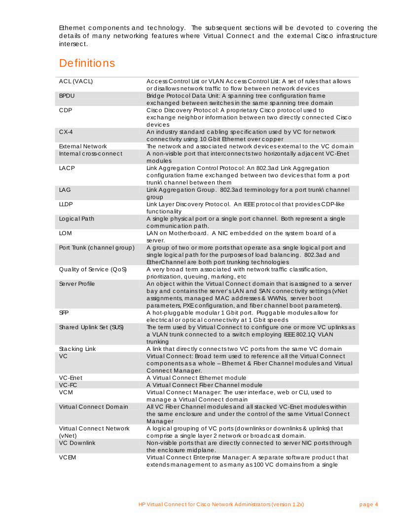
Definitions ACL (VACL) Access Control List or VLAN Access Control List: A set of rules that allows
or disallows network traffic to flow between network devices BPDU Bridge Protocol Data Unit: A spanning tree configuration frame
exchanged between switches in the same spanning tree domain CDP Cisco Discovery Protocol: A proprietary Cisco protocol used to
exchange neighbor information between two directly connected Cisco devices
CX-4 An industry standard cabling specification used by VC for network connectivity using 10 Gbit Ethernet over copper
External Network The network and associated network devices external to the VC domain Internal cross-connect A non-visible port that interconnects two horizontally adjacent VC-Enet
modules LACP Link Aggregation Control Protocol: An 802.3ad Link Aggregation
configuration frame exchanged between two devices that form a port trunk\channel between them
LAG Link Aggregation Group. 802.3ad terminology for a port trunk\channel group
LLDP Link Layer Discovery Protocol. An IEEE protocol that provides CDP-like functionality
Logical Path A single physical port or a single port channel. Both represent a single communication path.
LOM LAN on Motherboard. A NIC embedded on the system board of a server.
Port Trunk (channel group) A group of two or more ports that operate as a single logical port and single logical path for the purposes of load balancing. 802.3ad and EtherChannel are both port trunking technologies
Quality of Service (QoS) A very broad term associated with network traffic classification, prioritization, queuing, marking, etc
Server Profile An object within the Virtual Connect domain that is assigned to a server bay and contains the server’s LAN and SAN connectivity settings (vNet assignments, managed MAC addresses & WWNs, server boot parameters, PXE configuration, and fiber channel boot parameters).
SFP A hot-pluggable modular 1 Gbit port. Pluggable modules allow for electrical or optical connectivity at 1 Gbit speeds
Shared Uplink Set (SUS) The term used by Virtual Connect to configure one or more VC uplinks as a VLAN trunk connected to a switch employing IEEE 802.1Q VLAN trunking
Stacking Link A link that directly connects two VC ports from the same VC domain VC Virtual Connect: Broad term used to reference all the Virtual Connect
components as a whole – Ethernet & Fiber Channel modules and Virtual Connect Manager.
VC-Enet A Virtual Connect Ethernet module VC-FC A Virtual Connect Fiber Channel module VCM Virtual Connect Manager: The user interface, web or CLI, used to
manage a Virtual Connect domain Virtual Connect Domain All VC Fiber Channel modules and all stacked VC-Enet modules within
the same enclosure and under the control of the same Virtual Connect Manager
Virtual Connect Network (vNet)
A logical grouping of VC ports (downlinks or downlinks & uplinks) that comprise a single layer 2 network or broadcast domain.
VC Downlink Non-visible ports that are directly connected to server NIC ports through the enclosure midplane.
VCEM Virtual Connect Enterprise Manager: A separate software product that extends management to as many as 100 VC domains from a single
HP Virtual Connect for Cisco Network Administrators (version 1.2x) page 5
console. VC Uplink Visible ports on the VC-Enet module faceplate that provide external
connectivity for the enclosure. VLAN Trunk A single physical port or a single port channel with VLAN tagging
enabled. Used to provide connectivity to one or more VLANs over the same logical path.
XFP A hot-pluggable modular 10 Gbit port. Pluggable modules allow for electrical or optical connectivity at 10 Gbit speeds
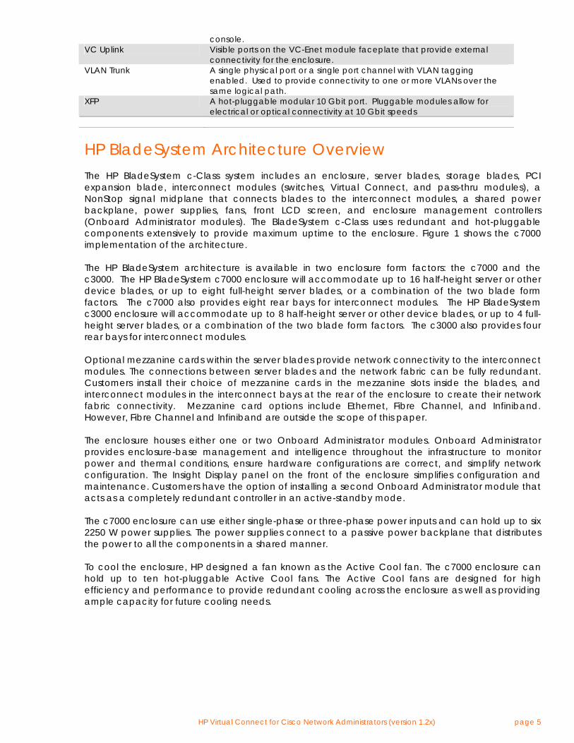
HP BladeSystem Architecture Overview The HP BladeSystem c-Class system includes an enclosure, server blades, storage blades, PCI expansion blade, interconnect modules (switches, Virtual Connect, and pass-thru modules), a NonStop signal midplane that connects blades to the interconnect modules, a shared power backplane, power supplies, fans, front LCD screen, and enclosure management controllers (Onboard Administrator modules). The BladeSystem c-Class uses redundant and hot-pluggable components extensively to provide maximum uptime to the enclosure. Figure 1 shows the c7000 implementation of the architecture. The HP BladeSystem architecture is available in two enclosure form factors: the c7000 and the c3000. The HP BladeSystem c7000 enclosure will accommodate up to 16 half-height server or other device blades, or up to eight full-height server blades, or a combination of the two blade form factors. The c7000 also provides eight rear bays for interconnect modules. The HP BladeSystem c3000 enclosure will accommodate up to 8 half-height server or other device blades, or up to 4 full-height server blades, or a combination of the two blade form factors. The c3000 also provides four rear bays for interconnect modules. Optional mezzanine cards within the server blades provide network connectivity to the interconnect modules. The connections between server blades and the network fabric can be fully redundant. Customers install their choice of mezzanine cards in the mezzanine slots inside the blades, and interconnect modules in the interconnect bays at the rear of the enclosure to create their network fabric connectivity. Mezzanine card options include Ethernet, Fibre Channel, and Infiniband. However, Fibre Channel and Infiniband are outside the scope of this paper. The enclosure houses either one or two Onboard Administrator modules. Onboard Administrator provides enclosure-base management and intelligence throughout the infrastructure to monitor power and thermal conditions, ensure hardware configurations are correct, and simplify network configuration. The Insight Display panel on the front of the enclosure simplifies configuration and maintenance. Customers have the option of installing a second Onboard Administrator module that acts as a completely redundant controller in an active-standby mode. The c7000 enclosure can use either single-phase or three-phase power inputs and can hold up to six 2250 W power supplies. The power supplies connect to a passive power backplane that distributes the power to all the components in a shared manner. To cool the enclosure, HP designed a fan known as the Active Cool fan. The c7000 enclosure can hold up to ten hot-pluggable Active Cool fans. The Active Cool fans are designed for high efficiency and performance to provide redundant cooling across the enclosure as well as providing ample capacity for future cooling needs.
HP Virtual Connect for Cisco Network Administrators (version 1.2x) page 6
Figure 1. Overview of c7000 Enclosure Components
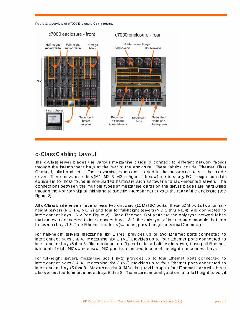
c-Class Cabling Layout The c-Class server blades use various mezzanine cards to connect to different network fabrics through the interconnect bays at the rear of the enclosure. These fabrics include Ethernet, Fiber Channel, Infiniband, etc. The mezzanine cards are inserted in the mezzanine slots in the blade server. These mezzanine slots (M1, M2, & M3 in Figure 2 below) are basically PCI-e expansion slots equivalent to those found in non-bladed hardware such as tower and rack-mounted servers. The connections between the multiple types of mezzanine cards on the server blades are hard-wired through the NonStop signal midplane to specific interconnect bays at the rear of the enclosure (see Figure 2). All c-Class blade servers have at least two onboard (LOM) NIC ports. These LOM ports, two for half-height servers (NIC 1 & NIC 2) and four for full-height servers (NIC 1 thru NIC4), are connected to interconnect bays 1 & 2 (see Figure 2). Since Ethernet LOM ports are the only type network fabric that are ever connected to interconnect bays 1 & 2, the only type of interconnect module that can be used in bays 1 & 2 are Ethernet modules (switches, pass-through, or Virtual Connect). For half-height servers, mezzanine slot 1 (M1) provides up to two Ethernet ports connected to interconnect bays 3 & 4. Mezzanine slot 2 (M2) provides up to four Ethernet ports connected to interconnect bays 5 thru 8. The maximum configuration for a half-height server, if using all Ethernet, is a total of eight NICs where each NIC port is connected to one of the eight interconnect bays. For full-height servers, mezzanine slot 1 (M1) provides up to four Ethernet ports connected to interconnect bays 3 & 4. Mezzanine slot 2 (M2) provides up to four Ethernet ports connected to interconnect bays 5 thru 8. Mezzanine slot 3 (M3) also provides up to four Ethernet ports which are also connected to interconnect bays 5 thru 8. The maximum configuration for a full-height server, if
HP Virtual Connect for Cisco Network Administrators (version 1.2x) page 7
using all Ethernet, is a total of 16 NICs, where two NIC ports are connected to each of the eight interconnect bays. Mezzanine slots may be populated with I/O technologies other than Ethernet (such as Fibre Channel or InfiniBand), but this paper focuses primarily on Ethernet.
Figure 2. Half-height and Full-height Blade Server I/O Mappings to Interconnect Bays for a c7000 Enclosure
Half-Height Server in a c7000 enclosure Server Bays Interconnect Bays
Full-Height Server in a c7000 enclosure Server Bays Interconnect Bays
(See Appendix B for c3000 enclosure port mapping)
Blade 9
Blade 1 1
NIC1 2
3 4
5 6
7 8
M1
M2
M2
1/2
3/4
5/6 7/8
1/2
3/4
5/6
7/8
1234
1234
12
NIC2
NIC1 NIC2
M1 12
1 NIC1
2
3 4
5 6
7 8
M1
M2
M3
1 2 3 4
1 2 3 4
1 2 3 4
NIC2
NIC3 NIC4
1/2
3/4
5/6 7/8
1/2
3/4
V7/8
Blade 1
HP Virtual Connect for Cisco Network Administrators (version 1.2x) page 8
c-Class Ethernet Interconnect Options The BladeSystem c7000 Enclosure offers a variety of interconnect options, including pass-thru modules, Ethernet and Fibre Channel switches, Virtual Connect modules, and high-bandwidth fabrics such as InfiniBand. The HP website (www.hp.com/go/bladesystem/interconnects) contains the most up-to-date information about the available c-Class interconnect modules. Ethernet Switches from Cisco and Blade Network Technologies (BNT) offer customers a traditional approach to administering the network. The primary value in blade switches is cable consolidation through high-speed uplinks and the shared blade power and cooling infrastructure.
Available Blade Switch Options: • Cisco Catalyst Blade Switch 3020 • HP GbE2c Ethernet Blade Switch • HP GbE2c Layer 2/3 Ethernet Blade Switch • HP 1:10Gb Ethernet BL-c Switch • HP 10Gb Ethernet BL-c Switch
Ethernet pass-thru modules are also available when direct one-to-one connections between servers and the LAN is required. HP Ethernet Pass-Thru Modules provide 16-port, transparent, 1:1 port connectivity between the server and an external Ethernet switch. Finally, Virtual Connect is also an option for customers for use in place of c-Class Ethernet switches or Ethernet pass-thru modules.
HP Virtual Connect Technology
Overview Virtual Connect is a set of interconnect modules and embedded software for HP BladeSystem c-Class enclosures that simplifies the setup and administration of server connections. The HP Virtual Connect portfolio includes the HP 1/10Gb Virtual Connect Ethernet Module for c-Class BladeSystem, the HP 1/10Gb-F Virtual Connect Ethernet Module for c-Class BladeSystem, and the HP 4Gb Virtual Connect Fibre Channel Module for c-Class BladeSystem. All modules are managed with the embedded HP Virtual Connect Manager or the optional Virtual Connect Enterprise Manager (VCEM). Virtual Connect implements server edge virtualization so that server administrators can upgrade, replace, or move server blades within their enclosures without changes being visible to the external LAN and SAN environments. The Virtual Connect Manager is embedded on the HP 1/10Gb Virtual Connect Ethernet Module and the HP 1/10Gb-F Virtual Connect Ethernet Module for c- Class BladeSystem and is accessed by Administrators through web links provided by the Onboard Administrator, through direct connection to the embedded Virtual Connect Manager web server, through a serial connection through the OA for CLI access, or through an SSH session for CLI access to the Virtual Connect Manager. A Virtual Connect Domain, configured using the Virtual Connect Manager, includes a single HP c-Class BladeSystem enclosure, all installed Virtual Connect modules and a total of 16 server bays that can be populated with a mixture of server and or storage blades. Within the VC domain, any server blade can be configured to access any LAN or SAN connected to a VC module, and a server blade can be used as a spare for any server blade within the same VC domain. By stacking (cabling) the Ethernet modules within the VC domain, every server blade in the domain can be configured to access any external network connection. Fibre Channel modules (VC-FC) within different I/O bays are each connected directly to individual FC SAN fabrics. With this
HP Virtual Connect for Cisco Network Administrators (version 1.2x) page 9
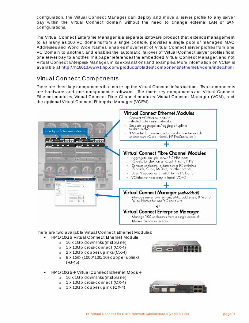
configuration, the Virtual Connect Manager can deploy and move a server profile to any server bay within the Virtual Connect domain without the need to change external LAN or SAN configurations. The Virtual Connect Enterprise Manager is a separate software product that extends management to as many as 100 VC domains from a single console, provides a single pool of managed MAC Addresses and World Wide Names, enables movement of Virtual Connect server profiles from one VC Domain to another, and enables the automatic failover of Virtual Connect server profiles from one server bay to another. This paper references the embedded Virtual Connect Manager, and not Virtual Connect Enterprise Manager, in its explanations and examples. More information on VCEM is available at:http://h18013.www1.hp.com/products/blades/components/ethernet/vcem/index.html Virtual Connect Components There are three key components that make up the Virtual Connect infrastructure. Two components are hardware and one component is software. The three key components are Virtual Connect Ethernet modules, Virtual Connect Fibre Channel modules, Virtual Connect Manager (VCM), and the optional Virtual Connect Enterprise Manager (VCEM).
There are two available Virtual Connect Ethernet Modules:
• HP 1/10Gb Virtual Connect Ethernet Module o 16 x 1Gb downlinks (midplane) o 1 x 10Gb cross-connect (CX-4) o 2 x 10Gb copper uplinks (CX-4) o 8 x 1Gb (1000/100/10) copper uplinks
(RJ-45)
• HP 1/10Gb-F Virtual Connect Ethernet Module o 16 x 1Gb downlinks (midplane) o 1 x 10Gb cross-connect (CX-4) o 1 x 10Gb copper uplink (CX-4)
HP Virtual Connect for Cisco Network Administrators (version 1.2x) page 10
o 2 x 10Gb SR or LR fiber uplinks (XFP) o 2 x 1Gb fiber uplinks (SFP) o 4 x 1Gb (1000/100/10)copper uplinks (RJ-45)
The purpose of the Virtual Connect Manager (VCM) is to function as the single point of administration for the Virtual Connect Domain. This means that all aspects of configuring, managing, and monitoring the Virtual Connect Domain and all VC Ethernet and Fiber Channel modules is provided by VCM. VCM runs embedded on either the HP 1/10Gb or the HP 1/10Gb-F Ethernet modules when installed in interconnect bay 1 or 2. VCM utilizes its own CPU, memory, and flash resources onboard the VC Ethernet modules. VCM runs in High Availability mode when Virtual Connect Ethernet modules are installed in both interconnect bays 1 and 2. By default, the Virtual Connect Ethernet module in interconnect bay 1 will be the active VCM and the Virtual Connect Ethernet module in interconnect bay 2 will be the standby VCM. The Virtual Connect Domain configuration is check pointed from the active VCM to the standby whenever configuration changes are made. In this way, if the Virtual Connect Ethernet module functioning as the active VCM fails, the standby Ethernet module can assume the role of active VCM without loss of Virtual Connect Domain configuration settings. Note: Even though VCM is only active on a single Virtual Connect Ethernet module at one time, this has nothing to do with the Ethernet connectivity functionality provided by the Virtual Connect Ethernet modules. All Virtual Connect modules in the domain are functionally active at all times and every port on every Virtual Connect module can be configured to actively carry network traffic at the same time. Virtual Connect Technical Specifications
• 128-Gbps bridging fabric • 2 Mb of dynamic memory (bridging buffer) with head-of-line blocking prevention • Line rate forwarding for all packet sizes and all conditions • Capacity of 16384 MAC addresses • Capacity of 1024 IGMP groups and bridging entries • Maximum transmission units up to 9216 bytes (jumbo frames) • Average single-module latency 3.8us at 64-byte frames • Average single-module latency 3.8us at 1518-byte frames
Virtual Connect Manager User Interfaces Virtual Connect Manager (VCM) provides three user interfaces for managing and monitoring the Virtual Connect Domain – Web, SSH CLI, and SNMP. The Web and SSH CLI interfaces provide nearly an identical set of features used to manage the Virtual Connect Domain. For more information on the specifics of these interfaces, please consult the Virtual Connect Users Guide (www.hp.com/go/bladesystem/documentation). VC’s SNMP implementation allows the administrator to monitor the Virtual Connect domain and associated modules. The SNMP configuration is controlled by the Virtual Connect Manager and applies to all modules in the VC domain. The SNMP agent software module residing on a primary module provides access to managed information using SNMP protocol. The managed information is presented as a hierarchical database called a MIB. Each element of the managed information is
HP Virtual Connect for Cisco Network Administrators (version 1.2x) page 11
identified by a unique identifier called Object ID. Basic SNMP support is provided for VC-Enet modules. The VC-Enet modules support the applicable groups of the following SNMP MIBs: • Compaq Host MIB • Compaq System Info MIB • RFC 3418 SNMPv2-MIB • RFC 2863 IF-MIB • RFC 4188 BRIDGE-MIB The VC-Enet modules support the following SNMP traps: • cpqHoSWRunningStatusChangeTrap from CPQ-HOST MIB • coldStart trapfrom SNMPv2-MIB Virtual Connect Port Descriptions The three types of ports are VC downlinks, VC uplinks, and internal cross-connects:
• VC Downlinks o Non-visible ports that are directly connected to server NIC ports through the
enclosure midplane. o Only role is to provide connectivity to directly connected blade server NICs
• VC Uplinks o Visible ports on the VC-Enet module faceplate that provide external connectivity for
the VC domain. o Roles include stacking link, network analyzer port (see Port Monitoring), normal mode
(providing external connectivity for one or more vNets or Shared Uplink Sets) • Internal cross-connects
o A non-visible port that interconnects two horizontally adjacent VC-Enet modules o Only role is to function as a stacking link
Overview of Virtual Connect Ethernet Connectivity While Virtual Connect provides many features, its primary purpose is to provide internal and external network connectivity for blade servers in a c-Class enclosure. For Ethernet, Virtual Connect accomplishes this purpose by bridging together, at layer 2, VC downlink ports (server NICs) with other VC downlink ports and with VC uplink ports connected to an external switched network. Virtual Connect provides the administrator with control over which uplinks and which downlinks are assigned to the same layer 2 network through the use of Virtual Connect Networks (vNets or Shared Uplink Sets). A VC Administrator defines vNets and, optionally, assigns VC uplinks to the vNets to provide external network connectivity. Once the vNets are defined, they are available for the Server Administrator to assign to server NIC ports. When a Server Admin moves a server profile from one server bay to another, the vNet assignments and, if used, managed MAC addresses (see section entitled “VC Managed MAC Addresses) are moved with the profile. This allows the server administrator to easily move the “Ethernet connectivity profile” for a server from one bay to another without requiring the assistance of the Network Administrator. A vNet can be used to bridge together multiple VC downlinks for an internal-to-the-enclosure-only network or a vNet can be used to bridge together one or more VC downlinks with one or more VC uplinks to provide external network connectivity for the blade servers in the enclosure. A vNet cannot be used to bridge together multiple VC uplinks to provide connectivity between two
HP Virtual Connect for Cisco Network Administrators (version 1.2x) page 12
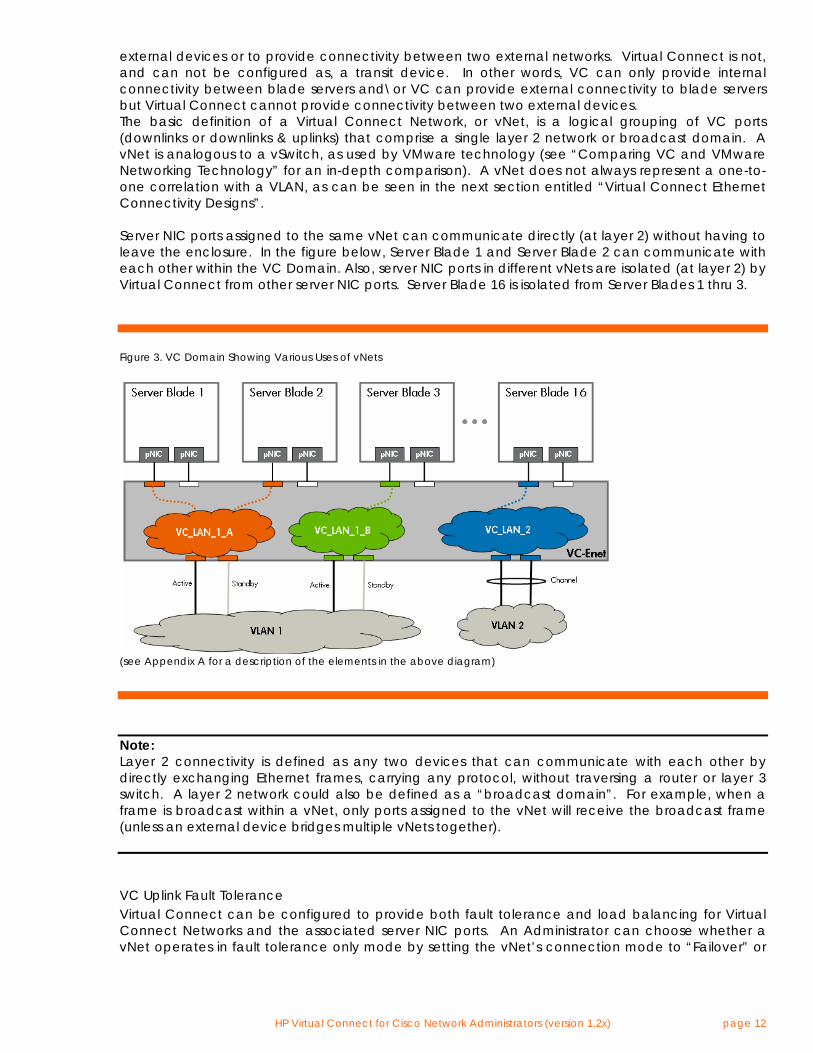
external devices or to provide connectivity between two external networks. Virtual Connect is not, and can not be configured as, a transit device. In other words, VC can only provide internal connectivity between blade servers and\or VC can provide external connectivity to blade servers but Virtual Connect cannot provide connectivity between two external devices. The basic definition of a Virtual Connect Network, or vNet, is a logical grouping of VC ports (downlinks or downlinks & uplinks) that comprise a single layer 2 network or broadcast domain. A vNet is analogous to a vSwitch, as used by VMware technology (see “Comparing VC and VMware Networking Technology” for an in-depth comparison). A vNet does not always represent a one-to-one correlation with a VLAN, as can be seen in the next section entitled “Virtual Connect Ethernet Connectivity Designs”. Server NIC ports assigned to the same vNet can communicate directly (at layer 2) without having to leave the enclosure. In the figure below, Server Blade 1 and Server Blade 2 can communicate with each other within the VC Domain. Also, server NIC ports in different vNets are isolated (at layer 2) by Virtual Connect from other server NIC ports. Server Blade 16 is isolated from Server Blades 1 thru 3.
Figure 3. VC Domain Showing Various Uses of vNets
(see Appendix A for a description of the elements in the above diagram)
Note: Layer 2 connectivity is defined as any two devices that can communicate with each other by directly exchanging Ethernet frames, carrying any protocol, without traversing a router or layer 3 switch. A layer 2 network could also be defined as a “broadcast domain”. For example, when a frame is broadcast within a vNet, only ports assigned to the vNet will receive the broadcast frame (unless an external device bridges multiple vNets together). VC Uplink Fault Tolerance Virtual Connect can be configured to provide both fault tolerance and load balancing for Virtual Connect Networks and the associated server NIC ports. An Administrator can choose whether a vNet operates in fault tolerance only mode by setting the vNet’s connection mode to “Failover” or
HP Virtual Connect for Cisco Network Administrators (version 1.2x) page 13
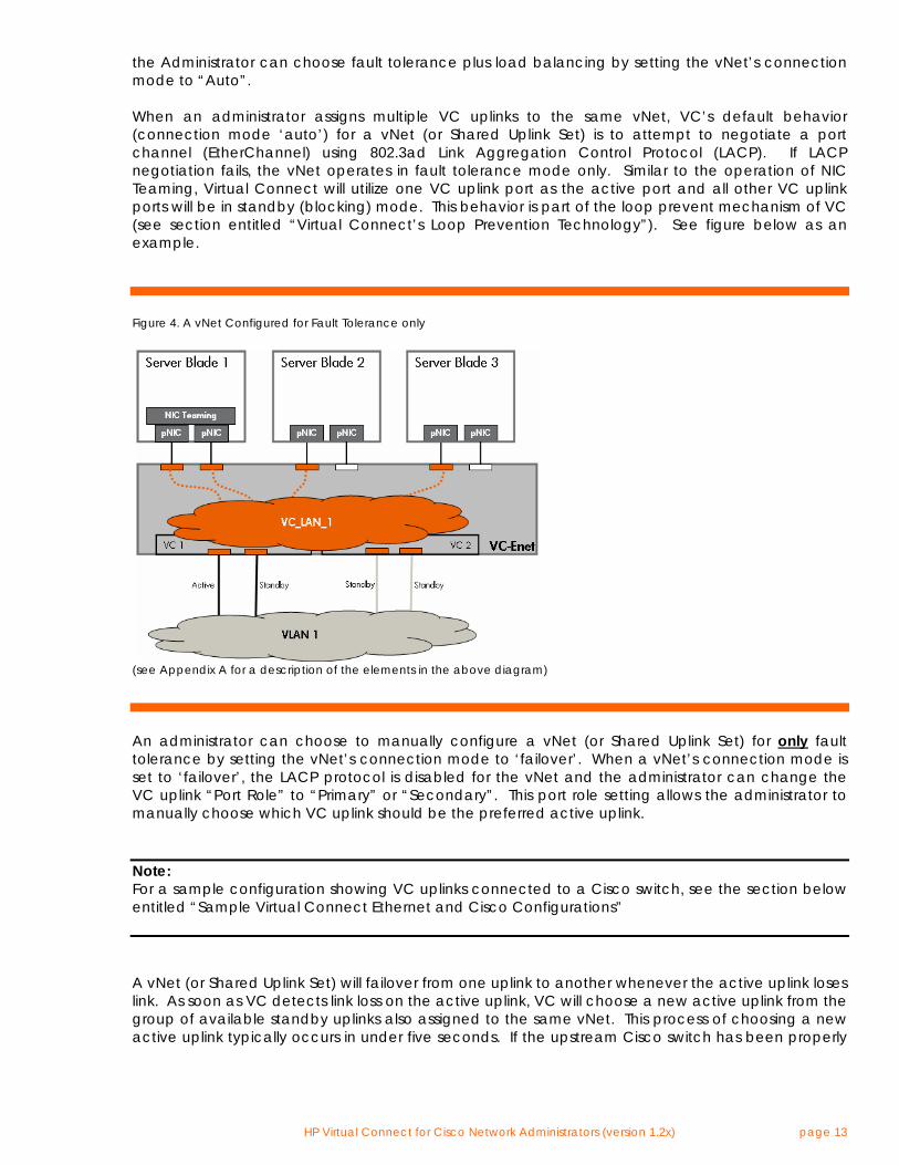
the Administrator can choose fault tolerance plus load balancing by setting the vNet’s connection mode to “Auto”. When an administrator assigns multiple VC uplinks to the same vNet, VC’s default behavior (connection mode ‘auto’) for a vNet (or Shared Uplink Set) is to attempt to negotiate a port channel (EtherChannel) using 802.3ad Link Aggregation Control Protocol (LACP). If LACP negotiation fails, the vNet operates in fault tolerance mode only. Similar to the operation of NIC Teaming, Virtual Connect will utilize one VC uplink port as the active port and all other VC uplink ports will be in standby (blocking) mode. This behavior is part of the loop prevent mechanism of VC (see section entitled “Virtual Connect’s Loop Prevention Technology”). See figure below as an example.
Figure 4. A vNet Configured for Fault Tolerance only
(see Appendix A for a description of the elements in the above diagram)
An administrator can choose to manually configure a vNet (or Shared Uplink Set) for only fault tolerance by setting the vNet’s connection mode to ‘failover’. When a vNet’s connection mode is set to ‘failover’, the LACP protocol is disabled for the vNet and the administrator can change the VC uplink “Port Role” to “Primary” or “Secondary”. This port role setting allows the administrator to manually choose which VC uplink should be the preferred active uplink. Note: For a sample configuration showing VC uplinks connected to a Cisco switch, see the section below entitled “Sample Virtual Connect Ethernet and Cisco Configurations” A vNet (or Shared Uplink Set) will failover from one uplink to another whenever the active uplink loses link. As soon as VC detects link loss on the active uplink, VC will choose a new active uplink from the group of available standby uplinks also assigned to the same vNet. This process of choosing a new active uplink typically occurs in under five seconds. If the upstream Cisco switch has been properly
HP Virtual Connect for Cisco Network Administrators (version 1.2x) page 14
configured on all the uplinks associated with the vNet, the server connectivity should be restored in under five seconds. If the previous active uplink has it’s link restored, VC will automatically failback to it. As long as the external Cisco switch port has been properly configured by enabling PortFast, connectivity to servers should be restored in under five seconds. Virtual Connect uses a mechanism called “Fast MAC Cache Failover” to proactively update the CAM tables on the upstream Cisco switch ports. Whenever a vNet fails over or fails back from one uplink to another, this mechanism will transmit a single frame on the new active uplink for every server MAC address that is active within the VC domain. Fast MAC Cache Failover enables VC to immediately update the external Cisco infrastructure with the new location of the active VC uplink for a particular vNet. Fast MAC Cache Failover is very similar to the CAM table update process used by Link-State Tracking on Cisco switches. VC Uplink Load Balancing Virtual Connect provides load balancing (and fault tolerance) across multiple VC uplinks on the same physical VC-Enet module by means of IEEE 802.3ad port trunking or port channeling (EtherChannel) using the Link Aggregation Control Protocol (LACP). The vNet (or Shared Uplink Set) must have its “connection mode” set to “auto” (default) and not in mode “failover”. If the external switch is a Cisco switch, the ports in the EtherChannel must be set to either “mode active” or “mode passive”. Both of these modes on the Cisco switch enable the use of 802.3ad LACP (the only port channeling protocol VC supports). VC does not support port channeling with Cisco switch ports when set to “mode on”, “mode desirable” or “mode auto”. Note: An EtherChannel can only be formed between VC and a Cisco switch if the VC vNet is set to connection mode “Auto” and the Cisco switch’s channel-group is set to either “mode active” or “mode passive”. There are four types of scenarios for port trunking\channeling with Virtual Connect Uplink Ports:
• Same VC Module, Same External Switch, Same Port Channel Group When VC uplinks from the same physical VC-Enet module are assigned to the same vNet (or Shared Uplink Set) and are connected to ports on the same external Cisco switch that are assigned to the same port channel group and have the LACP protocol enabled, then VC will automatically form a single port channel.
• Same VC Module, Same External Switch, Different Port Channel Groups When VC uplinks from the same physical VC-Enet module are assigned to the same vNet (or Shared Uplink Set) and are connected to ports on the same external Cisco switch that are assigned to different port channel groups and have the LACP protocol enabled, then VC may automatically form more than one port channel.
• Same VC Module, Different External Switches When VC uplinks from the same physical VC-Enet module are assigned to the same vNet (or Shared Uplink Set) and are connected to ports on different external Cisco switches that are assigned to port channel groups and have the LACP protocol enabled, then VC may automatically form more than one port channel.
• Different VC Module, Same or Different External Switches When VC uplinks from different physical VC-Enet modules are assigned to the same vNet (or Shared Uplink Set) and are connected to ports on the same (or different) external Cisco switch that are assigned to a port channel group and have the LACP protocol enabled, then VC may automatically form more than one port channel.
As described above, VC’s default behavior (connection mode ‘auto’) for a vNet is to attempt to negotiate a port channel (EtherChannel) using 802.3ad Link Aggregation Control Protocol (LACP). If LACP negotiation is successful for one or more sets of VC uplink ports, a port channel is formed
HP Virtual Connect for Cisco Network Administrators (version 1.2x) page 15
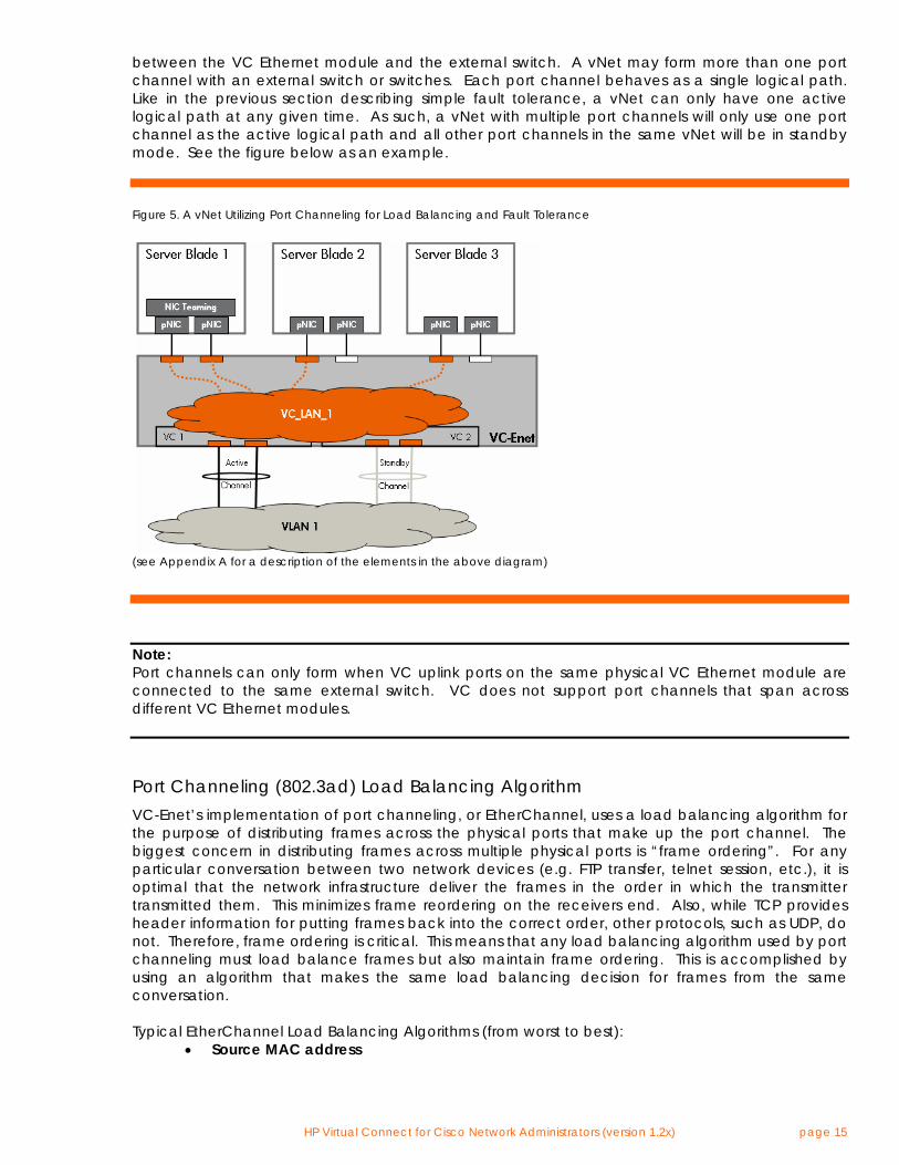
between the VC Ethernet module and the external switch. A vNet may form more than one port channel with an external switch or switches. Each port channel behaves as a single logical path. Like in the previous section describing simple fault tolerance, a vNet can only have one active logical path at any given time. As such, a vNet with multiple port channels will only use one port channel as the active logical path and all other port channels in the same vNet will be in standby mode. See the figure below as an example.
Figure 5. A vNet Utilizing Port Channeling for Load Balancing and Fault Tolerance
(see Appendix A for a description of the elements in the above diagram)
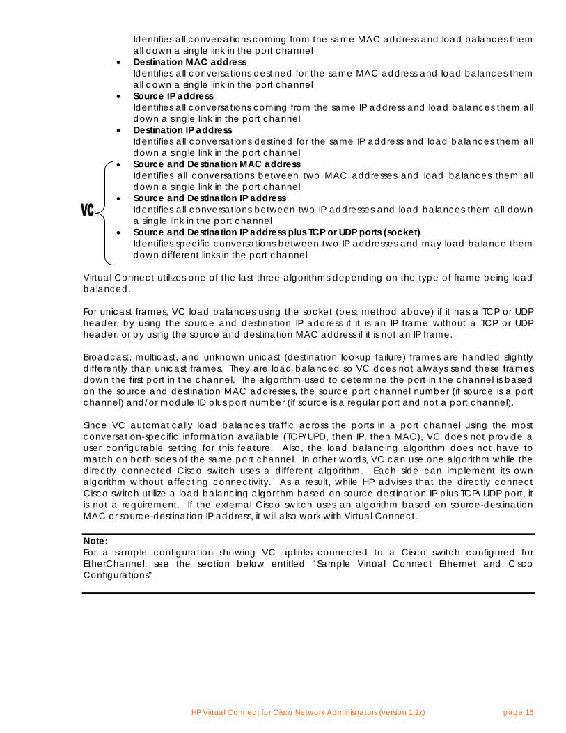
Note: Port channels can only form when VC uplink ports on the same physical VC Ethernet module are connected to the same external switch. VC does not support port channels that span across different VC Ethernet modules. Port Channeling (802.3ad) Load Balancing Algorithm VC-Enet’s implementation of port channeling, or EtherChannel, uses a load balancing algorithm for the purpose of distributing frames across the physical ports that make up the port channel. The biggest concern in distributing frames across multiple physical ports is “frame ordering”. For any particular conversation between two network devices (e.g. FTP transfer, telnet session, etc.), it is optimal that the network infrastructure deliver the frames in the order in which the transmitter transmitted them. This minimizes frame reordering on the receivers end. Also, while TCP provides header information for putting frames back into the correct order, other protocols, such as UDP, do not. Therefore, frame ordering is critical. This means that any load balancing algorithm used by port channeling must load balance frames but also maintain frame ordering. This is accomplished by using an algorithm that makes the same load balancing decision for frames from the same conversation. Typical EtherChannel Load Balancing Algorithms (from worst to best):
• Source MAC address
HP Virtual Connect for Cisco Network Administrators (version 1.2x) page 16
Identifies all conversations coming from the same MAC address and load balances them all down a single link in the port channel
• Destination MAC address Identifies all conversations destined for the same MAC address and load balances them all down a single link in the port channel
• Source IP address Identifies all conversations coming from the same IP address and load balances them all down a single link in the port channel
• Destination IP address Identifies all conversations destined for the same IP address and load balances them all down a single link in the port channel
• Source and Destination MAC address Identifies all conversations between two MAC addresses and load balances them all down a single link in the port channel
• Source and Destination IP address Identifies all conversations between two IP addresses and load balances them all down a single link in the port channel
• Source and Destination IP address plus TCP or UDP ports (socket) Identifies specific conversations between two IP addresses and may load balance them down different links in the port channel
Virtual Connect utilizes one of the last three algorithms depending on the type of frame being load balanced. For unicast frames, VC load balances using the socket (best method above) if it has a TCP or UDP header, by using the source and destination IP address if it is an IP frame without a TCP or UDP header, or by using the source and destination MAC address if it is not an IP frame. Broadcast, multicast, and unknown unicast (destination lookup failure) frames are handled slightly differently than unicast frames. They are load balanced so VC does not always send these frames down the first port in the channel. The algorithm used to determine the port in the channel is based on the source and destination MAC addresses, the source port channel number (if source is a port channel) and/or module ID plus port number (if source is a regular port and not a port channel). Since VC automatically load balances traffic across the ports in a port channel using the most conversation-specific information available (TCP/UPD, then IP, then MAC), VC does not provide a user configurable setting for this feature. Also, the load balancing algorithm does not have to match on both sides of the same port channel. In other words, VC can use one algorithm while the directly connected Cisco switch uses a different algorithm. Each side can implement its own algorithm without affecting connectivity. As a result, while HP advises that the directly connect Cisco switch utilize a load balancing algorithm based on source-destination IP plus TCP\UDP port, it is not a requirement. If the external Cisco switch uses an algorithm based on source-destination MAC or source-destination IP address, it will also work with Virtual Connect. Note: For a sample configuration showing VC uplinks connected to a Cisco switch configured for EtherChannel, see the section below entitled “Sample Virtual Connect Ethernet and Cisco Configurations”
HP Virtual Connect for Cisco Network Administrators (version 1.2x) page 17
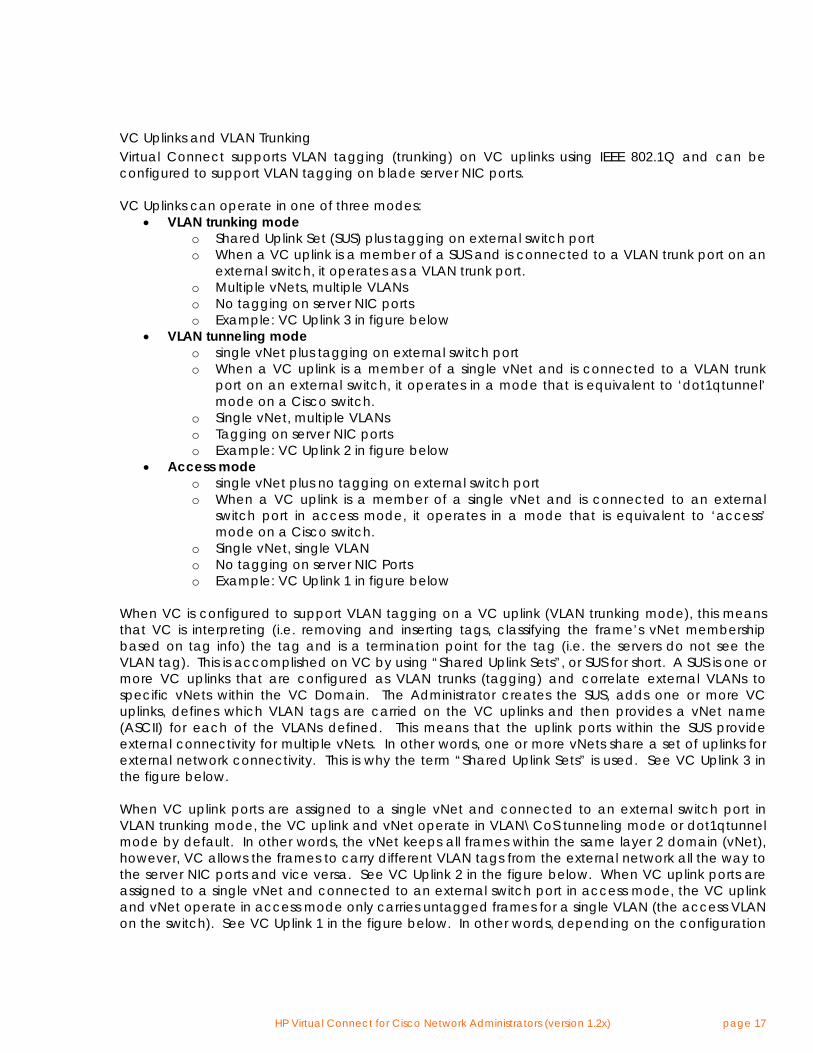
VC Uplinks and VLAN Trunking Virtual Connect supports VLAN tagging (trunking) on VC uplinks using IEEE 802.1Q and can be configured to support VLAN tagging on blade server NIC ports. VC Uplinks can operate in one of three modes:
• VLAN trunking mode o Shared Uplink Set (SUS) plus tagging on external switch port o When a VC uplink is a member of a SUS and is connected to a VLAN trunk port on an
external switch, it operates as a VLAN trunk port. o Multiple vNets, multiple VLANs o No tagging on server NIC ports o Example: VC Uplink 3 in figure below
• VLAN tunneling mode o single vNet plus tagging on external switch port o When a VC uplink is a member of a single vNet and is connected to a VLAN trunk
port on an external switch, it operates in a mode that is equivalent to ‘dot1qtunnel’ mode on a Cisco switch.
o Single vNet, multiple VLANs o Tagging on server NIC ports o Example: VC Uplink 2 in figure below
• Access mode o single vNet plus no tagging on external switch port o When a VC uplink is a member of a single vNet and is connected to an external
switch port in access mode, it operates in a mode that is equivalent to ‘access’ mode on a Cisco switch.
o Single vNet, single VLAN o No tagging on server NIC Ports o Example: VC Uplink 1 in figure below
When VC is configured to support VLAN tagging on a VC uplink (VLAN trunking mode), this means that VC is interpreting (i.e. removing and inserting tags, classifying the frame’s vNet membership based on tag info) the tag and is a termination point for the tag (i.e. the servers do not see the VLAN tag). This is accomplished on VC by using “Shared Uplink Sets”, or SUS for short. A SUS is one or more VC uplinks that are configured as VLAN trunks (tagging) and correlate external VLANs to specific vNets within the VC Domain. The Administrator creates the SUS, adds one or more VC uplinks, defines which VLAN tags are carried on the VC uplinks and then provides a vNet name (ASCII) for each of the VLANs defined. This means that the uplink ports within the SUS provide external connectivity for multiple vNets. In other words, one or more vNets share a set of uplinks for external network connectivity. This is why the term “Shared Uplink Sets” is used. See VC Uplink 3 in the figure below. When VC uplink ports are assigned to a single vNet and connected to an external switch port in VLAN trunking mode, the VC uplink and vNet operate in VLAN\CoS tunneling mode or dot1qtunnel mode by default. In other words, the vNet keeps all frames within the same layer 2 domain (vNet), however, VC allows the frames to carry different VLAN tags from the external network all the way to the server NIC ports and vice versa. See VC Uplink 2 in the figure below. When VC uplink ports are assigned to a single vNet and connected to an external switch port in access mode, the VC uplink and vNet operate in access mode only carries untagged frames for a single VLAN (the access VLAN on the switch). See VC Uplink 1 in the figure below. In other words, depending on the configuration
HP Virtual Connect for Cisco Network Administrators (version 1.2x) page 18
of the external switch port, a single vNet could represent a single VLAN or a single vNet could represent multiple VLANs.
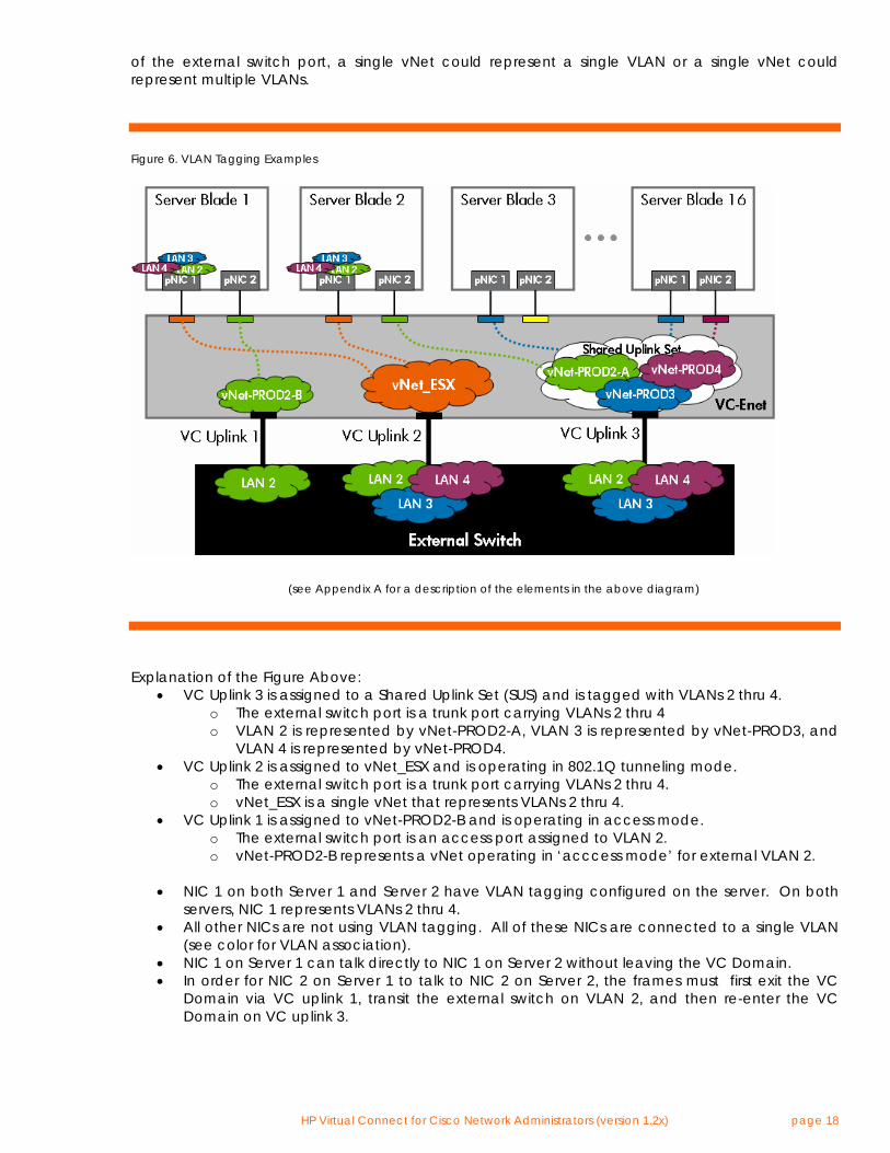
Figure 6. VLAN Tagging Examples
(see Appendix A for a description of the elements in the above diagram)
Explanation of the Figure Above:
• VC Uplink 3 is assigned to a Shared Uplink Set (SUS) and is tagged with VLANs 2 thru 4. o The external switch port is a trunk port carrying VLANs 2 thru 4 o VLAN 2 is represented by vNet-PROD2-A, VLAN 3 is represented by vNet-PROD3, and
VLAN 4 is represented by vNet-PROD4. • VC Uplink 2 is assigned to vNet_ESX and is operating in 802.1Q tunneling mode.
o The external switch port is a trunk port carrying VLANs 2 thru 4. o vNet_ESX is a single vNet that represents VLANs 2 thru 4.
• VC Uplink 1 is assigned to vNet-PROD2-B and is operating in access mode. o The external switch port is an access port assigned to VLAN 2. o vNet-PROD2-B represents a vNet operating in ‘acccess mode’ for external VLAN 2.
• NIC 1 on both Server 1 and Server 2 have VLAN tagging configured on the server. On both servers, NIC 1 represents VLANs 2 thru 4.
• All other NICs are not using VLAN tagging. All of these NICs are connected to a single VLAN (see color for VLAN association).
• NIC 1 on Server 1 can talk directly to NIC 1 on Server 2 without leaving the VC Domain. • In order for NIC 2 on Server 1 to talk to NIC 2 on Server 2, the frames must first exit the VC
Domain via VC uplink 1, transit the external switch on VLAN 2, and then re-enter the VC Domain on VC uplink 3.
HP Virtual Connect for Cisco Network Administrators (version 1.2x) page 19
Shared Uplink Sets manage uplink redundancy the same as individual vNets do. In other words, when multiple uplinks are assigned to a Shared Uplink Set, the uplinks can operate in failover-only mode or they can operate in port channeling (EtherChannel) mode. Also, all VLANs and associated vNets within a single Shared Uplink Set use the same active uplink or same active port channel. Note: For a sample configuration showing VC uplinks connected to a Cisco switch configured for VLAN trunking, see the section below entitled “Sample Virtual Connect Ethernet and Cisco Configurations”. The Cisco switch commands are the same for VC in VLAN Trunking mode or VC in VLAN Tunneling mode. Unsupported Cisco VLAN Protocols There are two proprietary Cisco VLAN protocols that Virtual Connect does not support – VTP and DTP. VTP, or VLAN Trunking Protocol, is a Cisco proprietary protocol used to manage a single VLAN database across multiple switches within the same domain. Since VC is not a Cisco device, VC does not support VTP. As such, there is no possibility that an improperly configured VC Domain can cause harm to the VTP Domain. Since VC does not support VTP, an administrator is required to add every VLAN that needs to be trunked on a VC uplink port. DTP, or Dynamic Trunking Protocol, is a Cisco proprietary protocol used for automating the VLAN trunking configuration between a pair of directly connected Cisco ports. With DTP enabled, one Cisco switch port can be configured for VLAN trunking and the partner switch port can automatically configure its VLAN trunking configuration to match. Since VC is not a Cisco device, VC does not support DTP. HP recommends that the Administrator disable DTP on the directly connected Cisco switch ports using the command “switchport nonegotiate”. Virtual Connect and NIC Teaming Virtual Connect supports NIC Teaming (or NIC bonding) on server NIC ports. For Windows on x86, VC supports Network Fault Tolerance (NFT) and Transmit Load Balancing (TLB) but does not support Switch-assisted Load Balancing (SLB). For Windows on Integrity, VC supports Network Fault Tolerance (NFT), Transmit Load Balancing (TLB), and static Dual Channel with only two NIC ports in the team, but does not support Switch-assisted Load Balancing (SLB). For Linux, VC supports any NIC bonding type that does not require 802.3ad (static or dynamic using LACP) on the server NIC ports. Virtual Connect also supports a feature called “SmartLink” that is enabled on vNets used by servers with NIC Teaming\bonding enabled. The SmartLink feature will disable the VC downlinks (server NIC ports) whenever all the VC uplinks for the associated vNet are unplugged. Basically, the SmartLink feature propagates a link-down event of a vNet’s uplinks to the server NICs in the team. This allows the NIC Teaming software to failover from one vNet (with all failed uplinks) to another vNet with functional uplinks. SmartLink is only used in NIC Teaming configurations when the NIC ports in the Team are connected to different vNets (see “Figure 12. VC Domain Showing Advanced Usage of
HP Virtual Connect for Cisco Network Administrators (version 1.2x) page 20
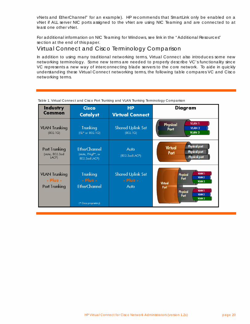
vNets and EtherChannel” for an example). HP recommends that SmartLink only be enabled on a vNet if ALL server NIC ports assigned to the vNet are using NIC Teaming and are connected to at least one other vNet. For additional information on NIC Teaming for Windows, see link in the “Additional Resources” section at the end of this paper. Virtual Connect and Cisco Terminology Comparison In addition to using many traditional networking terms, Virtual Connect also introduces some new networking terminology. Some new terms are needed to properly describe VC’s functionality since VC represents a new way of interconnecting blade servers to the core network. To aide in quickly understanding these Virtual Connect networking terms, the following table compares VC and Cisco networking terms.
Table 1. Virtual Connect and Cisco Port Trunking and VLAN Trunking Terminology Comparison
HP Virtual Connect for Cisco Network Administrators (version 1.2x) page 21
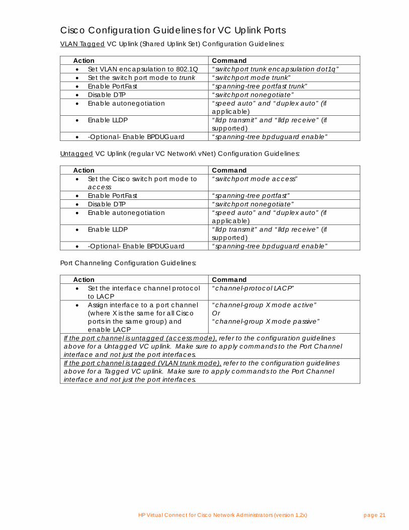
Cisco Configuration Guidelines for VC Uplink Ports VLAN Tagged VC Uplink (Shared Uplink Set) Configuration Guidelines: Action Command
• Set VLAN encapsulation to 802.1Q “switchport trunk encapsulation dot1q” • Set the switch port mode to trunk “switchport mode trunk” • Enable PortFast “spanning-tree portfast trunk” • Disable DTP “switchport nonegotiate” • Enable autonegotiation “speed auto” and “duplex auto” (if
applicable) • Enable LLDP “lldp transmit” and “lldp receive” (if
supported) • -Optional- Enable BPDUGuard “spanning-tree bpduguard enable”
Untagged VC Uplink (regular VC Network\vNet) Configuration Guidelines: Action Command
• Set the Cisco switch port mode to access
“switchport mode access”
• Enable PortFast “spanning-tree portfast” • Disable DTP “switchport nonegotiate” • Enable autonegotiation “speed auto” and “duplex auto” (if
applicable) • Enable LLDP “lldp transmit” and “lldp receive” (if
supported) • -Optional- Enable BPDUGuard “spanning-tree bpduguard enable”
Port Channeling Configuration Guidelines: Action Command
• Set the interface channel protocol to LACP
“channel-protocol LACP”
• Assign interface to a port channel (where X is the same for all Cisco ports in the same group) and enable LACP
“channel-group X mode active” Or “channel-group X mode passive”
If the port channel is untagged (access mode), refer to the configuration guidelines above for a Untagged VC uplink. Make sure to apply commands to the Port Channel interface and not just the port interfaces. If the port channel is tagged (VLAN trunk mode), refer to the configuration guidelines above for a Tagged VC uplink. Make sure to apply commands to the Port Channel interface and not just the port interfaces.
HP Virtual Connect for Cisco Network Administrators (version 1.2x) page 22
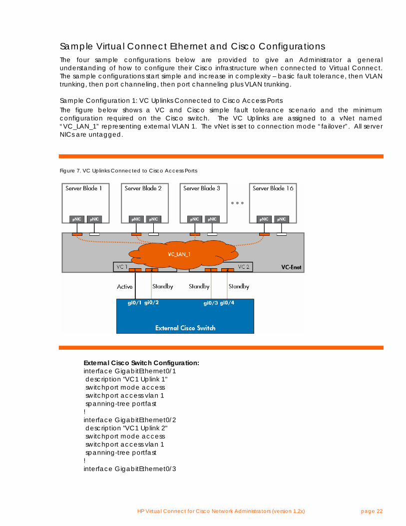
Sample Virtual Connect Ethernet and Cisco Configurations The four sample configurations below are provided to give an Administrator a general understanding of how to configure their Cisco infrastructure when connected to Virtual Connect. The sample configurations start simple and increase in complexity – basic fault tolerance, then VLAN trunking, then port channeling, then port channeling plus VLAN trunking. Sample Configuration 1: VC Uplinks Connected to Cisco Access Ports The figure below shows a VC and Cisco simple fault tolerance scenario and the minimum configuration required on the Cisco switch. The VC Uplinks are assigned to a vNet named “VC_LAN_1” representing external VLAN 1. The vNet is set to connection mode “failover”. All server NICs are untagged.
Figure 7. VC Uplinks Connected to Cisco Access Ports
External Cisco Switch Configuration: interface GigabitEthernet0/1 description "VC1 Uplink 1" switchport mode access switchport access vlan 1 spanning-tree portfast ! interface GigabitEthernet0/2 description "VC1 Uplink 2" switchport mode access switchport access vlan 1 spanning-tree portfast ! interface GigabitEthernet0/3
HP Virtual Connect for Cisco Network Administrators (version 1.2x) page 23
description "VC2 Uplink 1" switchport mode access switchport access vlan 1 spanning-tree portfast ! interface GigabitEthernet0/4 description "VC2 Uplink 2" switchport mode access switchport access vlan 1 spanning-tree portfast
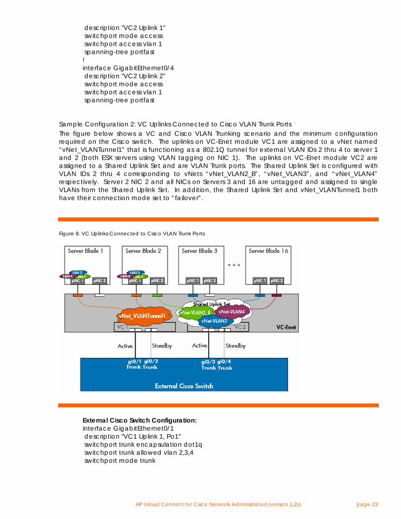
Sample Configuration 2: VC Uplinks Connected to Cisco VLAN Trunk Ports The figure below shows a VC and Cisco VLAN Trunking scenario and the minimum configuration required on the Cisco switch. The uplinks on VC-Enet module VC1 are assigned to a vNet named “vNet_VLANTunnel1” that is functioning as a 802.1Q tunnel for external VLAN IDs 2 thru 4 to server 1 and 2 (both ESX servers using VLAN tagging on NIC 1). The uplinks on VC-Enet module VC2 are assigned to a Shared Uplink Set and are VLAN Trunk ports. The Shared Uplink Set is configured with VLAN IDs 2 thru 4 corresponding to vNets “vNet_VLAN2_B”, “vNet_VLAN3”, and “vNet_VLAN4” respectively. Server 2 NIC 2 and all NICs on Servers 3 and 16 are untagged and assigned to single VLANs from the Shared Uplink Set. In addition, the Shared Uplink Set and vNet_VLANTunnel1 both have their connection mode set to “failover”.
Figure 8. VC Uplinks Connected to Cisco VLAN Trunk Ports
External Cisco Switch Configuration: interface GigabitEthernet0/1 description "VC1 Uplink 1, Po1" switchport trunk encapsulation dot1q switchport trunk allowed vlan 2,3,4 switchport mode trunk
HP Virtual Connect for Cisco Network Administrators (version 1.2x) page 24
spanning-tree portfast trunk ! interface GigabitEthernet0/2 description "VC1 Uplink 2, Po1" switchport trunk encapsulation dot1q switchport trunk allowed vlan 2,3,4 switchport mode trunk spanning-tree portfast trunk ! interface GigabitEthernet0/3 description "VC2 Uplink 1, Po2" switchport trunk encapsulation dot1q switchport trunk allowed vlan 2,3,4 switchport mode trunk spanning-tree portfast trunk ! interface GigabitEthernet0/4 description "VC2 Uplink 2, Po2" switchport trunk encapsulation dot1q switchport trunk allowed vlan 2,3,4 switchport mode trunk spanning-tree portfast trunk
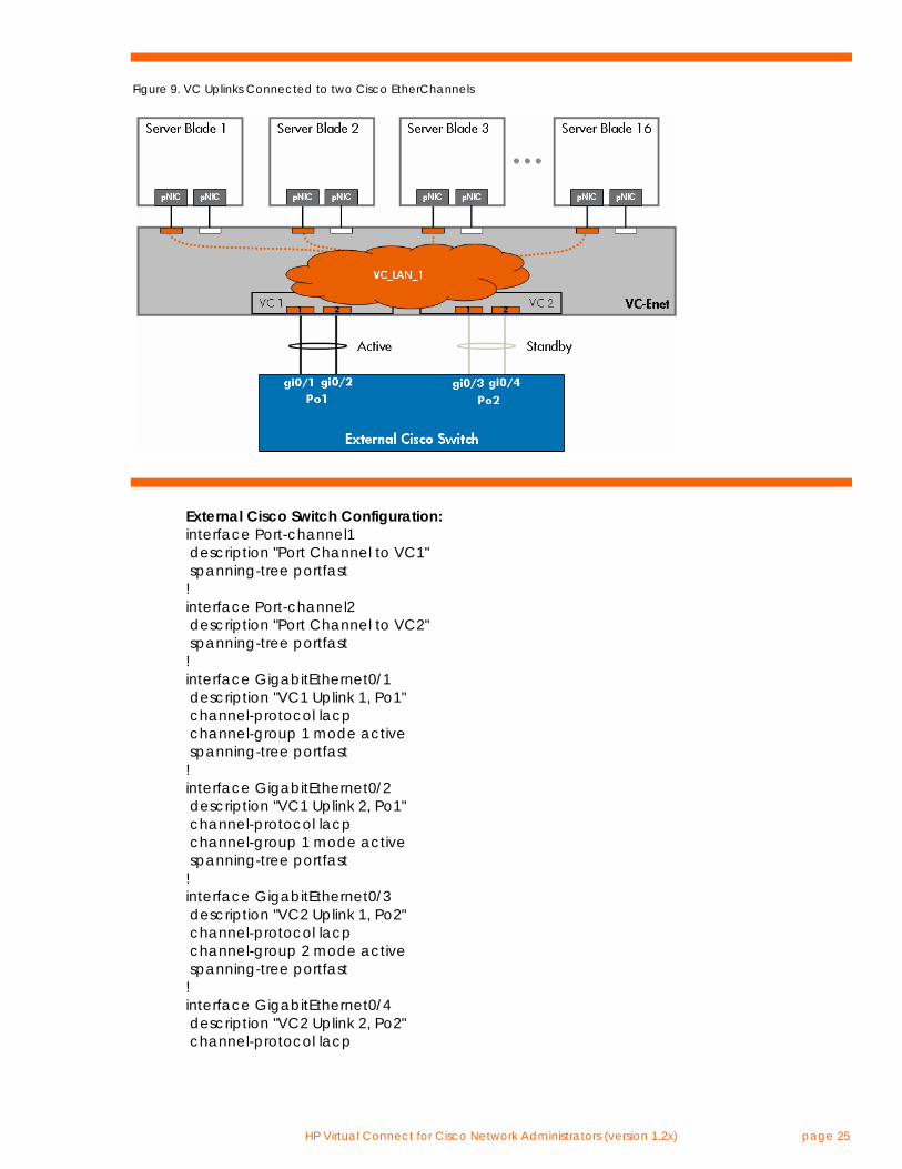
Sample Configuration 3: VC Uplinks Connected to a Cisco EtherChannel The figure below shows a VC and Cisco port channeling scenario and the minimum configuration required on the Cisco switch. The VC Uplinks are assigned to a vNet named “VC_LAN_1” representing external VLAN 1. The vNet is set to connection mode “auto”. All server NICs are untagged.
HP Virtual Connect for Cisco Network Administrators (version 1.2x) page 25
Figure 9. VC Uplinks Connected to two Cisco EtherChannels
External Cisco Switch Configuration: interface Port-channel1 description "Port Channel to VC1" spanning-tree portfast ! interface Port-channel2 description "Port Channel to VC2" spanning-tree portfast ! interface GigabitEthernet0/1 description "VC1 Uplink 1, Po1" channel-protocol lacp channel-group 1 mode active spanning-tree portfast ! interface GigabitEthernet0/2 description "VC1 Uplink 2, Po1" channel-protocol lacp channel-group 1 mode active spanning-tree portfast ! interface GigabitEthernet0/3 description "VC2 Uplink 1, Po2" channel-protocol lacp channel-group 2 mode active spanning-tree portfast ! interface GigabitEthernet0/4 description "VC2 Uplink 2, Po2" channel-protocol lacp
HP Virtual Connect for Cisco Network Administrators (version 1.2x) page 26
channel-group 2 mode active spanning-tree portfast
Note: The PortFast command in this scenario is only required under the Port Channel interfaces and is not required on the physical interfaces. However, best practice is to include the PortFast command under the physical interface just in case the port channel is dissolved and the uplinks resort to simple failover mode.
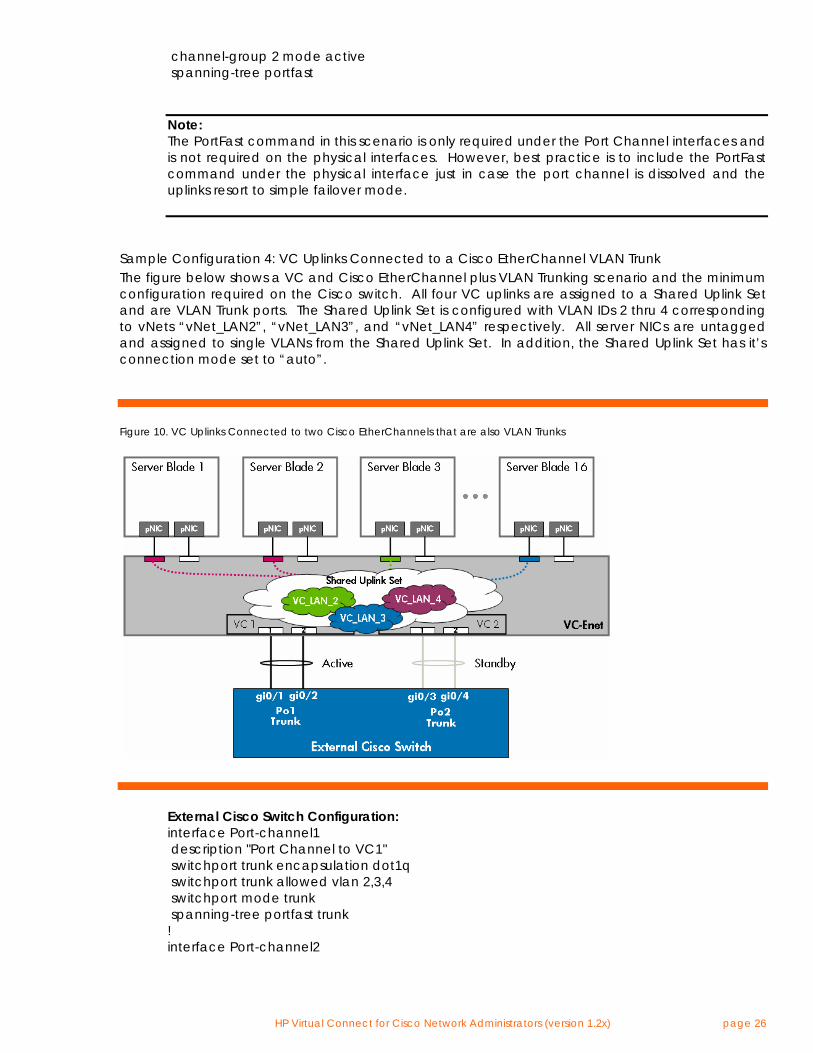
Sample Configuration 4: VC Uplinks Connected to a Cisco EtherChannel VLAN Trunk The figure below shows a VC and Cisco EtherChannel plus VLAN Trunking scenario and the minimum configuration required on the Cisco switch. All four VC uplinks are assigned to a Shared Uplink Set and are VLAN Trunk ports. The Shared Uplink Set is configured with VLAN IDs 2 thru 4 corresponding to vNets “vNet_LAN2”, “vNet_LAN3”, and “vNet_LAN4” respectively. All server NICs are untagged and assigned to single VLANs from the Shared Uplink Set. In addition, the Shared Uplink Set has it’s connection mode set to “auto”.
Figure 10. VC Uplinks Connected to two Cisco EtherChannels that are also VLAN Trunks
External Cisco Switch Configuration: interface Port-channel1 description "Port Channel to VC1" switchport trunk encapsulation dot1q switchport trunk allowed vlan 2,3,4 switchport mode trunk spanning-tree portfast trunk ! interface Port-channel2
HP Virtual Connect for Cisco Network Administrators (version 1.2x) page 27
description "Port Channel to VC2" switchport trunk encapsulation dot1q switchport trunk allowed vlan 2,3,4 switchport mode trunk spanning-tree portfast trunk ! interface GigabitEthernet0/1 description "VC1 Uplink 1, Po1" switchport trunk encapsulation dot1q switchport trunk allowed vlan 2,3,4 switchport mode trunk channel-protocol lacp channel-group 1 mode active spanning-tree portfast trunk ! interface GigabitEthernet0/2 description "VC1 Uplink 2, Po1" switchport trunk encapsulation dot1q switchport trunk allowed vlan 2,3,4 switchport mode trunk channel-protocol lacp channel-group 1 mode active spanning-tree portfast trunk ! interface GigabitEthernet0/3 description "VC2 Uplink 1, Po2" switchport trunk encapsulation dot1q switchport trunk allowed vlan 2,3,4 switchport mode trunk channel-protocol lacp channel-group 2 mode active spanning-tree portfast trunk ! interface GigabitEthernet0/4 description "VC2 Uplink 2, Po2" switchport trunk encapsulation dot1q switchport trunk allowed vlan 2,3,4 switchport mode trunk channel-protocol lacp channel-group 2 mode active spanning-tree portfast trunk Note: The “PortFast Trunk” command and the trunking commands in this scenario are only required under the Port Channel interfaces and are not required on the physical interfaces. However, best practice is to configure the physical interface the same as the port channel interface just in case the port channel is dissolved and the uplinks resort to simple failover mode.
Advanced Virtual Connect Ethernet Designs Virtual Connect’s implementation of vNets allows for administrators to implement creative solutions to address many different complex networking designs. Typically, a vNet represents a single VLAN. However, a single VLAN can be represented within a Virtual Connect Domain by multiple vNets. By
HP Virtual Connect for Cisco Network Administrators (version 1.2x) page 28
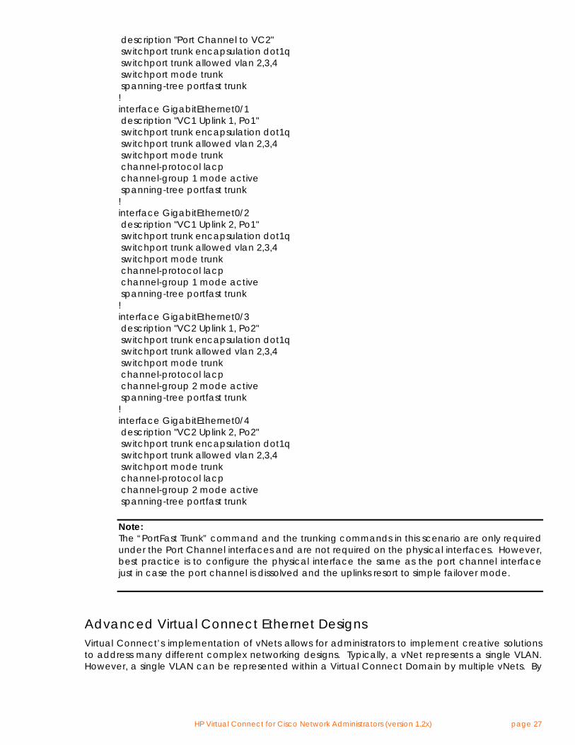
using different vNets for the same VLAN, an administrator can control traffic flow on a per server NIC basis. Below are some examples. Advanced VC-Enet Designs: Example Design #1 Referring to Figure 12, an administrator could use one vNet (VC_LAN_1_A) to couple a NIC on Server 1 and a NIC on Server 2 with a VC uplink that is connected to an external switch port assigned to VLAN 1. In this case, VC_LAN_1_A represents VLAN 1 within the VC Domain. Both Server 1 and Server 2 can talk directly with each other within VC_LAN_1_A, without leaving the VC Domain, and both servers can talk to devices on VLAN 1 via the active VC uplink port. In addition, an administrator could create another vNet (VC_LAN_1_B) and assign Server 3 to it. Virtual Connect does not allow Server 3’s NIC port to directly communicate with any other NIC port within this VC Domain since there are no other NIC ports assigned to VC_LAN_1_B. VC_LAN_1_B also represents VLAN 1 within the VC Domain. Server 3 effectively has its own dedicated VC uplinks to reach VLAN 1. If the external switched network permits it, Server 3 can communicate with Server 1 and 2 by exiting the VC Domain via the active uplink for VC_LAN_1_B, transiting the external Cisco switch, and reentering the VC Domain on the active uplink for VC_LAN_1_A.
Figure 11. VC Domain Showing Various Uses of vNets
(see Appendix A for a description of the elements in the above diagram)
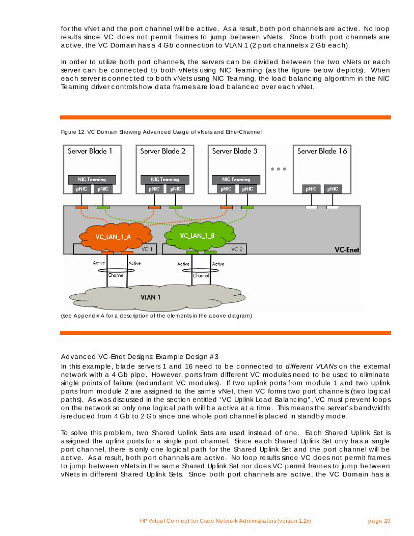
Advanced VC-Enet Designs: Example Design #2 Another example of an advanced configuration using vNets is depicted in the figure below. In diagram below, blade servers 1 thru 3 need to be connected to the external network with a 4 Gb pipe. However, ports from different VC modules need to be used to eliminate single points of failure (redundant VC modules). If two uplink ports from module 1 and two uplink ports from module 2 are assigned to the same vNet, then VC forms two port channels (two logical paths). As was discussed in the section entitled ‘VC Uplink Load Balancing”, VC must prevent loops on the network so only one logical path will be active at a time. This means the server’s bandwidth is reduced from 4 Gb to 2 Gb since one whole channel is placed in standby mode. To solve this problem, two vNets are used instead of one. Each vNet is assigned the uplink ports for a single port channel. Since each vNet only has a single port channel, there is only one logical path
HP Virtual Connect for Cisco Network Administrators (version 1.2x) page 29
for the vNet and the port channel will be active. As a result, both port channels are active. No loop results since VC does not permit frames to jump between vNets. Since both port channels are active, the VC Domain has a 4 Gb connection to VLAN 1 (2 port channels x 2 Gb each). In order to utilize both port channels, the servers can be divided between the two vNets or each server can be connected to both vNets using NIC Teaming (as the figure below depicts). When each server is connected to both vNets using NIC Teaming, the load balancing algorithm in the NIC Teaming driver controls how data frames are load balanced over each vNet.
Figure 12. VC Domain Showing Advanced Usage of vNets and EtherChannel
(see Appendix A for a description of the elements in the above diagram)
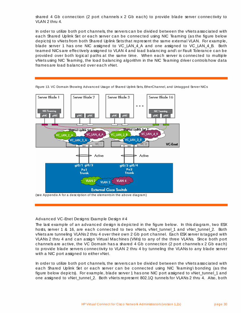
Advanced VC-Enet Designs: Example Design #3 In this example, blade servers 1 and 16 need to be connected to different VLANs on the external network with a 4 Gb pipe. However, ports from different VC modules need to be used to eliminate single points of failure (redundant VC modules). If two uplink ports from module 1 and two uplink ports from module 2 are assigned to the same vNet, then VC forms two port channels (two logical paths). As was discussed in the section entitled ‘VC Uplink Load Balancing”, VC must prevent loops on the network so only one logical path will be active at a time. This means the server’s bandwidth is reduced from 4 Gb to 2 Gb since one whole port channel is placed in standby mode. To solve this problem, two Shared Uplink Sets are used instead of one. Each Shared Uplink Set is assigned the uplink ports for a single port channel. Since each Shared Uplink Set only has a single port channel, there is only one logical path for the Shared Uplink Set and the port channel will be active. As a result, both port channels are active. No loop results since VC does not permit frames to jump between vNets in the same Shared Uplink Set nor does VC permit frames to jump between vNets in different Shared Uplink Sets. Since both port channels are active, the VC Domain has a
HP Virtual Connect for Cisco Network Administrators (version 1.2x) page 30
shared 4 Gb connection (2 port channels x 2 Gb each) to provide blade server connectivity to VLAN 2 thru 4. In order to utilize both port channels, the servers can be divided between the vNets associated with each Shared Uplink Set or each server can be connected using NIC Teaming (as the figure below depicts) to vNets from both Shared Uplink Sets that represent the same external VLAN. For example, blade server 1 has one NIC assigned to VC_LAN_4_A and one assigned to VC_LAN_4_B. Both teamed NICs are effectively assigned to VLAN 4 and load balancing and\or Fault Tolerance can be provided over both logical paths at the same time. When each server is connected to multiple vNets using NIC Teaming, the load balancing algorithm in the NIC Teaming driver controls how data frames are load balanced over each vNet.
Figure 13. VC Domain Showing Advanced Usage of Shared Uplink Sets, EtherChannel, and Untagged Server NICs
(see Appendix A for a description of the elements in the above diagram)
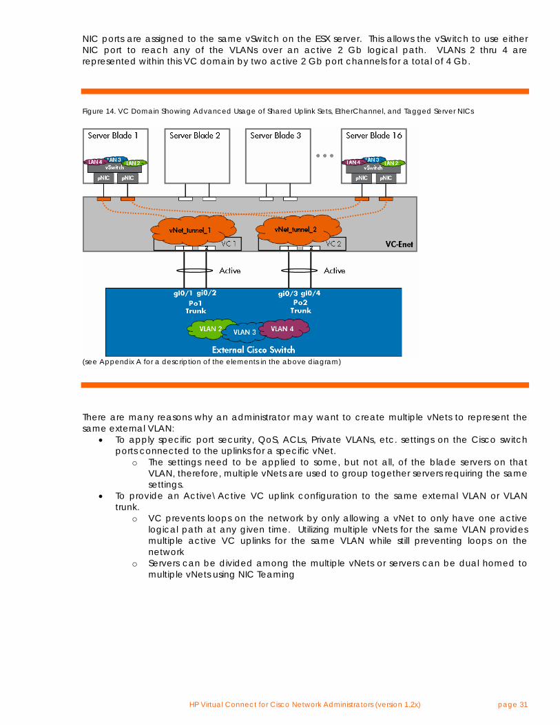
Advanced VC-Enet Designs: Example Design #4 The last example of an advanced design is depicted in the figure below. In this diagram, two ESX hosts, server 1 & 16, are each connected to two vNets, vNet_tunnel_1 and vNet_tunnel_2. Both vNets are tunneling VLANs 2 thru 4 over their own 2 Gb port channel. Each ESX server is tagged with VLANs 2 thru 4 and can assign Virtual Machines (VMs) to any of the three VLANs. Since both port channels are active, the VC Domain has a shared 4 Gb connection (2 port channels x 2 Gb each) to provide blade servers connectivity to VLAN 2 thru 4 by tunneling the VLANs to any blade server with a NIC port assigned to either vNet. In order to utilize both port channels, the servers can be divided between the vNets associated with each Shared Uplink Set or each server can be connected using NIC Teaming\bonding (as the figure below depicts). For example, blade server 1 has one NIC port assigned to vNet_tunnel_1 and one assigned to vNet_tunnel_2. Both vNets represent 802.1Q tunnels for VLANs 2 thru 4. Also, both
HP Virtual Connect for Cisco Network Administrators (version 1.2x) page 31
NIC ports are assigned to the same vSwitch on the ESX server. This allows the vSwitch to use either NIC port to reach any of the VLANs over an active 2 Gb logical path. VLANs 2 thru 4 are represented within this VC domain by two active 2 Gb port channels for a total of 4 Gb.
Figure 14. VC Domain Showing Advanced Usage of Shared Uplink Sets, EtherChannel, and Tagged Server NICs
(see Appendix A for a description of the elements in the above diagram)
There are many reasons why an administrator may want to create multiple vNets to represent the same external VLAN:
• To apply specific port security, QoS, ACLs, Private VLANs, etc. settings on the Cisco switch ports connected to the uplinks for a specific vNet.
o The settings need to be applied to some, but not all, of the blade servers on that VLAN, therefore, multiple vNets are used to group together servers requiring the same settings.
• To provide an Active\Active VC uplink configuration to the same external VLAN or VLAN trunk.
o VC prevents loops on the network by only allowing a vNet to only have one active logical path at any given time. Utilizing multiple vNets for the same VLAN provides multiple active VC uplinks for the same VLAN while still preventing loops on the network
o Servers can be divided among the multiple vNets or servers can be dual homed to multiple vNets using NIC Teaming
HP Virtual Connect for Cisco Network Administrators (version 1.2x) page 32
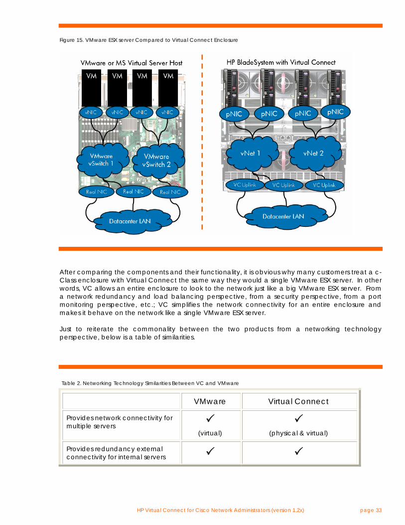
Comparing VC and VMware Networking Technology One method of understanding how Virtual Connect operates on the LAN is to compare the Virtual Connect networking components and their functionality to the networking components of a VMware ESX server. Since the networking technology used in a VMware ESX server is commonly understood and accepted by many customers, understanding the many similarities between VC and a VMware ESX server will help an implementer have a better understanding of how Virtual Connect looks to, and behaves on, the external network. Just to be clear, Virtual Connect and a VMware ESX server are fundamentally different products and address completely different needs within the datacenter. This comparison is strictly about understanding the similarities between the two products in regards to networking technology in order to better understand Virtual Connect. A Description of the VMware Components: Referencing the figure below, the VMware ESX server (left) is a single physical server running server virtualization software (VMware) that allows the physical server to host one or more instances of a virtual server, called a Virtual Machine (VM). In addition, the VMware ESX server provides external network connectivity to the internal servers (VMs) using a virtual (software) implementation of a layer 2 bridge, called a vSwitch. The VM virtual NICs (vNics) are assigned to one of the vSwitches and the vSwitches are then associated with real physical NICs residing in I/O slots on the VMware ESX server. The vSwitches can have one or more physical NICs (uplinks) assigned to them to provide external network connectivity. If more than one physical NIC is assigned to the same vSwitch, network redundancy and/or load balancing is provided for the internal servers (VMs) assigned to that vSwitch. The physical NICs then present one or more MAC addresses to the external network, depending on the number of VMs communicating to the external network through each physical NIC. A Comparative Description of the VC Components: Referencing the figure below, the c-Class enclosure (right) is a single physical enclosure that hosts one or more real physical servers, called a blade server. In addition, the c-Class enclosure provides external network connectivity to the internal servers (blade servers) using a hardware implementation of a layer 2 bridge, called a Virtual Connect Ethernet network (vNet). The blade server physical NICs (pNics) are assigned to one of the vNets and the vNets are then associated with real physical VC uplink ports from VC-Enet modules residing in the I/O bays on the c-Class enclosure. The vNets can have one or more VC uplinks assigned to them to provide external network connectivity. If more than one VC uplink is assigned to the same vNet, network redundancy and/or load balancing is provided for the internal servers (blade servers) assigned to that vNet. The VC uplinks then present one or more MAC addresses to the external network, depending on the number of blade servers communicating to the external network through each VC uplink.
HP Virtual Connect for Cisco Network Administrators (version 1.2x) page 33
Figure 15. VMware ESX server Compared to Virtual Connect Enclosure
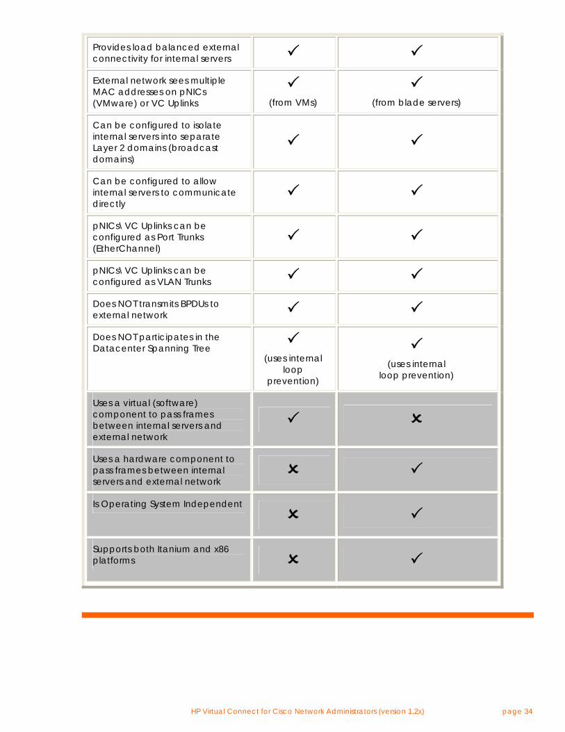
After comparing the components and their functionality, it is obvious why many customers treat a c-Class enclosure with Virtual Connect the same way they would a single VMware ESX server. In other words, VC allows an entire enclosure to look to the network just like a big VMware ESX server. From a network redundancy and load balancing perspective, from a security perspective, from a port monitoring perspective, etc.; VC simplifies the network connectivity for an entire enclosure and makes it behave on the network like a single VMware ESX server. Just to reiterate the commonality between the two products from a networking technology perspective, below is a table of similarities.
Table 2. Networking Technology Similarities Between VC and VMware
VMware Virtual Connect
Provides network connectivity for multiple servers
(virtual)
(physical & virtual)
Provides redundancy external connectivity for internal servers
HP Virtual Connect for Cisco Network Administrators (version 1.2x) page 34
Provides load balanced external connectivity for internal servers
External network sees multiple MAC addresses on pNICs (VMware) or VC Uplinks
(from VMs)
(from blade servers)
Can be configured to isolate internal servers into separate Layer 2 domains (broadcast domains)
Can be configured to allow internal servers to communicate directly
pNICs\VC Uplinks can be configured as Port Trunks (EtherChannel)
pNICs\VC Uplinks can be configured as VLAN Trunks
Does NOT transmits BPDUs to external network Does NOT participates in the Datacenter Spanning Tree
(uses internal
loop prevention)
(uses internal
loop prevention)
Uses a virtual (software) component to pass frames between internal servers and external network
Uses a hardware component to pass frames between internal servers and external network
Is Operating System Independent Supports both Itanium and x86 platforms
HP Virtual Connect for Cisco Network Administrators (version 1.2x) page 35
Virtual Connect’s Loop Prevention Technology Virtual Connect’s loop prevention technology is best described by building on what was discussed in the section above, “Comparing VC and VMware Networking Technology”. VC’s loop prevention technology is very similar to the NIC Teaming\bonding technology used by ProLiant servers. Referring back to the figure above comparing VMware and VC, it can be seen that the ESX server is using NIC bonding technology to provide load balancing and\or fault tolerance for vSwitch 1 and for the associated VMs. Even though vSwitch 1 is redundantly connected to the Data Center LAN, no loops are formed. In addition, Spanning Tree is not needed between the ESX server and the Data Center LAN to prevent the loop. Instead, the NIC bonding technology on the ESX host prevents loops on the network by only allowing one logical path (single NIC port or single channel group\port trunk) to be active at one time. In comparison, VC uplinks prevent loops in the same manner. In other words, on a per Virtual Connect network (vNet) basis, each vNet prevents loops on the Data Center LAN by only allowing one active logical path at a time. The behavior of the VC uplink ports associated with a vNet can be compared to the NIC ports associated with a vSwitch. In both cases, Spanning Tree is not needed to prevent loops on the Data Center LAN. Instead, in both cases “port bonding” technology is used to only allow a single active logical path at any given time. Stacking Virtual Connect Ethernet Modules Virtual Connect can be configured by an Administrator to allow any VC uplink on any VC Ethernet module to provide external connectivity for any server downlink. VC can also be configured to allow connectivity between any set of server downlinks on any VC Ethernet module. Virtual Connect provides this flexible connectivity through the use of ‘stacking links’ between VC Ethernet modules. Stacking links allow all VC Ethernet modules in the VC Domain to be configured as, and operate as, a single device (except for port channeling). Stacking links are to a group of VC Ethernet modules what the PCI bus is for a team of server NICs – a common communication path allowing all devices to work together as one. When any two Virtual Connect Ethernet modules from the same VC domain are directly connected together using 1 Gb or 10 Gb ports, the two modules automatically negotiate, using LLDP, the link as a stacking link. No manual configuration is required to make an uplink a stacking link. Simply connecting two VC uplinks together is all that is required. In the figure below, the green horizontal lines represent the internal stacking links that exist between horizontally-adjacent VC modules by default. The orange vertical lines represent the external stacking links that HP recommends customer install using 10 Gb or 1 Gb ports. The minimum recommendations below provide stacking link redundancy for each VC Ethernet module. Note: Stacking links are required for all Virtual Connect Ethernet modules in the same Virtual Connect Domain.
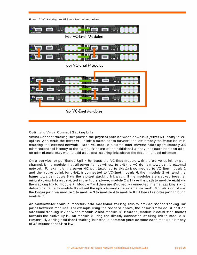
HP Virtual Connect for Cisco Network Administrators (version 1.2x) page 36
Figure 16. VC Stacking Link Minimum Recommendations
Optimizing Virtual Connect Stacking Links Virtual Connect stacking links provide the physical path between downlinks (server NIC ports) to VC uplinks. As a result, the fewer VC uplinks a frame has to traverse, the less latency the frame incurs in reaching the external network. Each VC module a frame must traverse adds approximately 3.8 microseconds of latency to the frame. Because of the additional latency that each hop can add, an administrator may wish to add additional stacking links above the recommended minimum. On a per-vNet or per-Shared Uplink Set basis, the VC-Enet module with the active uplink, or port channel, is the module that all server frames will use to exit the VC domain towards the external network. For example, if a server NIC port (assigned to vNet1) is connected to VC-Enet module 2 and the active uplink for vNet1 is connected to VC-Enet module 6, then module 2 will send the frame towards module 8 via the shortest stacking link path. If the modules are stacked together using stacking links as depicted in the figure above, module 2 will take the path to module eight via the stacking link to module 7. Module 7 will then use it’s directly connected internal stacking link to deliver the frame to module 8 and out the uplink towards the external network. Module 2 could use the longer path via module 1 to module 3 to module 4 to module 8 if it loses its shorter path through module 7. An administrator could purposefully add additional stacking links to provide shorter stacking link paths between modules. For example using the scenario above, the administrator could add an additional stacking link between module 2 and module 8. If added, module 2 could send frames towards the active uplink on module 8 using the directly connected stacking link to module 8. Purposefully adding additional stacking links is not a common practice since each module’s latency of 3.8 microseconds is so low.
HP Virtual Connect for Cisco Network Administrators (version 1.2x) page 37
VC Managed MAC Addresses One of the many features provided by Virtual Connect is the ability to “manage” the blade server MAC addresses. Specifically, Virtual Connect ‘manages’ the blade server MAC addresses. Virtual Connect does not ‘virtualize’ the blade server MAC addresses. Many VC implementers don’t appreciate the difference between ‘virtualized’ MAC addresses and ‘managed’ MAC addresses. A ‘virtualized’ MAC address is a MAC address that is not really owned and used by a physical NIC. Often, a virtualized MAC address is a MAC address that replaces the real MAC address of a physical NIC without the server’s knowledge. In other words, the server thinks it is communicating on the network with MAC address X, however, some device is replacing real MAC address X with a virtual MAC address Y. Many of the benefits of MAC address management are lost in this type of implementation. A ‘managed’ MAC address is a MAC address that really is owned and used by a physical NIC. The server has simply been assigned, by the administrator, to use a specific MAC address on a specific physical NIC port. This managed MAC address, for all intents and purposes, appears to the server as the MAC address that was burned into the physical NIC at the factory. The benefits of VC Managed MAC addresses are:
• WYSIWYG - What You See (on the server) Is What You Get (on the network) There is no discrepancy between what the server thinks its MAC address is and what the external network sees as the server’s MAC address. This dramatically reduces the complexity of troubleshooting network related issues.
• Server application licensing is maintained after hardware changes
Many server application licensing mechanisms can key off the server’s MAC addresses. If the server’s MAC address changes (replacing a failed NIC, booting server image on a different physical server, etc.), then the application licensing may require re-licensing using the new MAC address. Virtualized MAC addresses do not prevent this problem. However, VC’s use of managed MAC addresses does prevent this problem since the server image will always see the VC managed MAC address regardless of which physical server it is running on.
• No Performance impact on network devices
Virtualized MAC addresses can require that a network device (e.g. switch) manipulate every frame a server transmits to replace the server’s MAC address with the virtualized MAC address. Also, when the source MAC address is edited by the network device, the frames checksum (CRC) has to be recomputed by the network device. The more frames a server transmits, the more work the network device has to do, which can have an impact on the performance of the network device. Alternatively, VC’s use of managed MAC addresses means the server transmits with the managed MAC address. No device on the network (VC or switch) is required to manipulate the server’s frames. This results in absolutely no performance impact on the network.
When a blade server with VC managed MAC addresses is removed from the enclosure (or when a VC Server Profile is unassigned from a server blade while still in the enclosure) the blade server automatically reverts back to the actual MAC addresses burned into the physical NICs at the factory. This prevents any issues with duplicate MAC addresses on the network caused by moving blade servers around within the data center. Virtual Connect Manager (VCM) provides three domain-wide choices for managing the blade server MAC addresses:
HP Virtual Connect for Cisco Network Administrators (version 1.2x) page 38
• Static, factory-default MAC addresses As the name suggests, this setting tells Virtual Connect to not manage the server MAC addresses. The server will only use the original factory burned-in MAC address.
• User-defined This setting allows the Administrator to define a Locally Administered MAC address range that Virtual Connect will use to assign to blade servers.
• HP Pre-defined (recommended) This setting tells Virtual Connect to assign server MAC addresses from the pool of MAC addresses that HP has reserved. This option allows the Administrator to choose from one of 64 ranges of 1024 MAC addresses.
In addition, when using either the User-defined or HP Pre-defined settings as the domain-wide default setting, each individual VC Server Profile can optionally override the domain-wide setting by selecting to use the factory-default MAC address instead. Important points about VC managed MAC addresses:
• VC only manages the MAC address of physical NIC ports on a blade server. VC does not manage the MAC address used by virtual servers that may run on a physical server.
• A server reverts to the factory-default MAC address when removed from the enclosure or when no VC Server Profile is applied to it.
• VC generates 2 MAC addresses per NIC port in order to support multi-function adapters that may require more than one MAC address per port.
• Customers requiring a centralized database for managing the VC managed MAC address pools should consider implementing Virtual Connect Enterprise Manager. See www.hp.com/go/vcem for more details.
Spanning Tree Since Virtual Connect does not present itself to the external Cisco network as another “Ethernet switch”, the subject of “spanning tree interoperability” is not an applicable topic when discussing the two products. In other words, in the same way that a server (with multiple NICs) does not need to be configured for spanning tree, Virtual Connect (with multiple uplinks that look like NICs to the external Cisco network) does not need to be configured for spanning tree either. This means that the network administrator does not have to worry about STP interoperability issues between VC and Cisco since VC uplink ports do not transmit or receive STP BPDUs (Spanning Tree configuration frames) and cannot interfere with the external switched infrastructure’s implementation of STP any more than a multihomed server can. This also means that all questions about PVST+ support, Rapid Spanning Tree, MST, etc. are not applicable for Virtual Connect deployment discussions. Since VC uplink ports simply look to the network like “regular old server ports” with multiple MAC addresses, HP recommends that Cisco downlink ports connected to the VC uplink ports be configured as if they are connected directly to server NIC ports. In other words, configure the Cisco downlink ports as “access” or “trunk” ports with PortFast enabled. Enabling BPDUGuard is also an acceptable option for customers that regularly enable it for other Cisco switch ports connected directly to server ports. In summary, since Virtual Connect allows the c-Class enclosure to connect to the external network in much the same way as a VMware ESX server connects to the external network, it is easy to understand why Virtual Connect, just like a VMware ESX server, does not participate in the external network’s spanning tree domain.
HP Virtual Connect for Cisco Network Administrators (version 1.2x) page 39
PortFast The Spanning Tree PortFast feature was designed for Cisco switch ports connected to edge devices, like server NIC ports. This feature allows a Cisco switch port to bypass the ‘listening’ and ‘learning’ stages of spanning tree and quickly transition to the ‘forwarding’ stage. By enabling this feature, edge devices are allowed to immediately begin communication on the network instead of having to wait on Spanning Tree to determine if it needs to block the port to prevent a loop – a process that can take 30+ seconds with default Spanning Tree timers. Since edge devices do not present a loop on the network, Spanning Tree is not needed to prevent loops and can be effectively bypassed by using the PortFast feature. The benefit of this feature is that server NIC ports can immediately communicate on the network when plugged in rather than timing out for 30 or more seconds. This is especially useful for time sensitive protocols such as PXE and DHCP. Since VC uplinks operate on the network as an edge device (like teamed server NICs), Spanning Tree is not needed on the directly connected Cisco switch ports. This means that PortFast can be enabled on the Cisco switch ports directly connected to VC uplinks. Note: The interface command to enable PortFast on a Cisco access port is “spanning-tree portfast”. The interface command to enable PortFast on a Cisco trunk port is “spanning-tree portfast trunk”. BPDU Guard BPDU Guard is a safety feature for Cisco switch ports that have PortFast enabled. Enabling BPDU Guard allows the switch to monitor for the reception of BPDU frames (spanning tree configuration frames) on the port configured for PortFast. When a BPDU is received on a switch port with PortFast and BPDU Guard enabled, BPDU Guard will cause the switch port to err-disable (shutdown). Since ports with PortFast enabled should never be connected to another switch (which transmits BPDUs), BPDU Guard protects against PortFast-enabled ports from being connected to other switches. This prevents loops caused by bypassing Spanning Tree on that port and this prevents any device connected to that port from becoming the root bridge. Since VC behaves as an edge device on the network and since VC does not participate in the data center spanning tree (i.e. doesn’t transmit BPDUs on VC uplinks), BPDU Guard can be used, if desired, on Cisco switch ports connected to VC uplinks. Note: The interface command to enable BPDU Guard on a Cisco port is “spanning-tree bpduguard enable”. Unidirectional Link Detection (UDLD) UDLD is a Cisco proprietary feature that only operates between two directly connected Cisco devices. The purpose of UDLD is to detect unidirectional links (UniDirectional Link Detection) in situations where spanning tree is being used to detect and prevent loops. If a unidirectional link goes undetected, spanning tree won’t properly detect the loop and won’t block the port to prevent a loop on the network. Since spanning tree is not used between VC uplinks and external Cisco switches, a spanning tree loop caused by a unidirectional link is not possible. Therefore, UDLD is not required nor supported on Virtual Connect uplinks.
HP Virtual Connect for Cisco Network Administrators (version 1.2x) page 40
Quality of Service In the current version of firmware, Virtual Connect does not support any user-configurable settings for traffic classification, marking, or prioritization. In addition, VC does not utilize layer 2 quality of service markings (802.1p Class of Service) nor layer 3 quality of service markings (TOS, DSCP) for frame prioritization. However, just like with any server-to-Cisco-switch deployment, QoS settings can be applied to the Cisco switch port connected to VC uplinks. If an Administrator needs the blade server NIC ports to receive layer 2 QoS markings (Class of Service), then the server NIC ports will need to be assigned to a vNet operating in 802.1Q\p tunneling mode. See the section above entitled “VC Uplinks and VLAN Trunking” for more information.
Security
ACLs & VLAN ACLs In the current version of firmware, Virtual Connect does not support user-configurable port or VLAN ACLs. However, an Administrator can specifically design the deployment of vNets to make use of ACLs or VACLs configured on the upstream Cisco switch. In the figure below as an example, all four blade servers are on VLAN 1 even though they are split between two different vNets. Since the uplink ports for both vNets are connected to Cisco switch ports assigned to VLAN 1, both vNets represent VLAN 1 within the VC Domain. While server 1 can communicate directly with Server 2 without leaving the VC Domain, Server 1 cannot talk to Servers 3 or 4 without transiting the external Cisco switch. Server 1’s traffic will exit the VC domain via vNet VC_LAN1_A connected to interface gi0/1, be switched by the Cisco switch over to interface gi0/3, and reach Server 3 via the vNet VC_LAN1_B. Since Server 1’s traffic must transit the external Cisco switch to reach either Server 3 or Server 4, Server 1’s traffic will be subject to any port ACLs or VLAN ACLs configured on the external Cisco switch. In this case, the Administrator could apply a VACL on VLAN 1 of the external Cisco switch to prevent Server 1 from communicating with Server 3 while still allowing Server 1 to communicate with Server 4. The scenario above is just one example of the many ways an Administrator can creatively use vNets to accommodate complex network configurations.
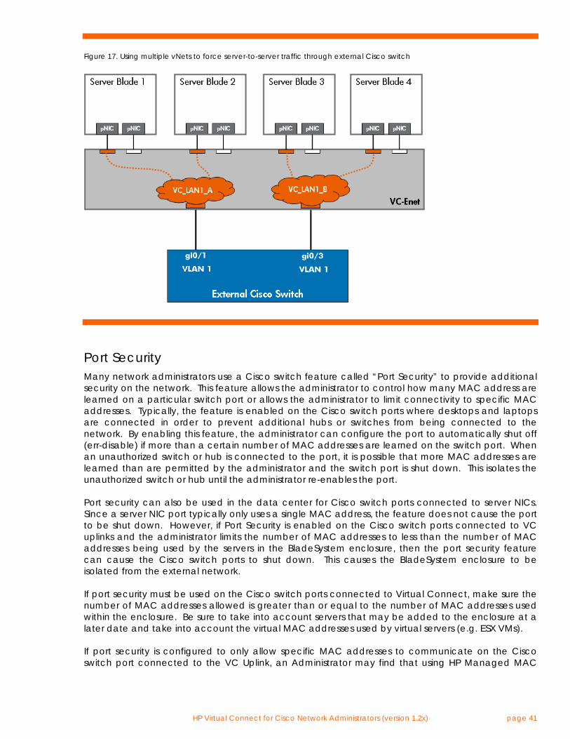
HP Virtual Connect for Cisco Network Administrators (version 1.2x) page 41
Figure 17. Using multiple vNets to force server-to-server traffic through external Cisco switch
Port Security Many network administrators use a Cisco switch feature called “Port Security” to provide additional security on the network. This feature allows the administrator to control how many MAC address are learned on a particular switch port or allows the administrator to limit connectivity to specific MAC addresses. Typically, the feature is enabled on the Cisco switch ports where desktops and laptops are connected in order to prevent additional hubs or switches from being connected to the network. By enabling this feature, the administrator can configure the port to automatically shut off (err-disable) if more than a certain number of MAC addresses are learned on the switch port. When an unauthorized switch or hub is connected to the port, it is possible that more MAC addresses are learned than are permitted by the administrator and the switch port is shut down. This isolates the unauthorized switch or hub until the administrator re-enables the port. Port security can also be used in the data center for Cisco switch ports connected to server NICs. Since a server NIC port typically only uses a single MAC address, the feature does not cause the port to be shut down. However, if Port Security is enabled on the Cisco switch ports connected to VC uplinks and the administrator limits the number of MAC addresses to less than the number of MAC addresses being used by the servers in the BladeSystem enclosure, then the port security feature can cause the Cisco switch ports to shut down. This causes the BladeSystem enclosure to be isolated from the external network. If port security must be used on the Cisco switch ports connected to Virtual Connect, make sure the number of MAC addresses allowed is greater than or equal to the number of MAC addresses used within the enclosure. Be sure to take into account servers that may be added to the enclosure at a later date and take into account the virtual MAC addresses used by virtual servers (e.g. ESX VMs). If port security is configured to only allow specific MAC addresses to communicate on the Cisco switch port connected to the VC Uplink, an Administrator may find that using HP Managed MAC
HP Virtual Connect for Cisco Network Administrators (version 1.2x) page 42
addresses with a user-defined range will simply the task. Simply configure port security to allow the same range of MAC addresses that are manually configured for the user-defined range. Whether an administrator is configuring port security to allow a certain number of MAC address or to allow specific MAC addresses, they must configure all Cisco ports assigned to the same vNet (or Shared Uplink Set) with the same port security settings in order to eliminate communication problems after a VC uplink failover. Private VLANs Private VLANs, or PVLANs, is a Cisco feature that allows switch ports assigned to the same VLAN to be configured for layer 2 isolation from other switch ports in the same VLAN. The benefit of this type of feature is enhanced security. For example, an Administrator can assign several servers to the same VLAN, utilizing the same IP subnet, and only allow the servers to directly communicate with the default gateway but not with each other. In the current release of VC firmware, Virtual Connect does not implement support for Private VLANs within a single vNet. However, an Administrator can achieve complete Layer 2 separation between server ports by assigning the server ports to separate vNets. Each vNet is a self-contained Layer 2 network\broadcast domain. Virtual Connect does not internally permit frames to pass between vNets. This means that a customer can use multiple vNets to isolate servers from each other within VC. An Administrator can use multiple vNets to extend the function of PVLANs configured on the upstream Cisco switch. In the example below, two VC vNets and a Cisco Private VLAN have been used to create two “community” groups and one promiscuous port. All four servers are on the same VLAN (VLAN 1), however, they are segregated at Layer 2 within VC because they are assigned to two different vNets (VC_LAN1_A & VC_LAN1_B). These two vNets are uplinked into a Cisco switch where VLAN 1 has been configured as a Private VLAN. Interface gi0/1 connected to VC_LAN1_A is an “isolated” port, so it only permits VC_LAN1_A to communicate with the router port (promiscuous). Also, VC_LAN1_B is connected to interface gi0/3 configured as “isolated” for VLAN 1, so it can also only talk to the router. Server 1 and Server 2 can directly communicate with each other within the VC Domain, however, they both would have to transit the external Cisco switch in order to communicate with Server 3 and Server 4. As a result, all communication from Server 1 or 2 to Server 3 or 4 is subject to the PVLAN configuration on the external switch. If gi0/1 and gi0/3 are isolated ports and gi0/5 is a promiscuous port, then Server 1 and Server 2 can communicate with each other and with the router, but they cannot communicate with Server 3 or 4. The same is true for Server 3 and 4 – they can communicate with each other and the router, but not Servers 1 and 2. Both VC_LAN1_A and VC_LAN1_B function as Community VLANs with the PVLAN. Note: all servers are on the same VLAN (VLAN 1) and can be assigned IP addresses from the same subnet.
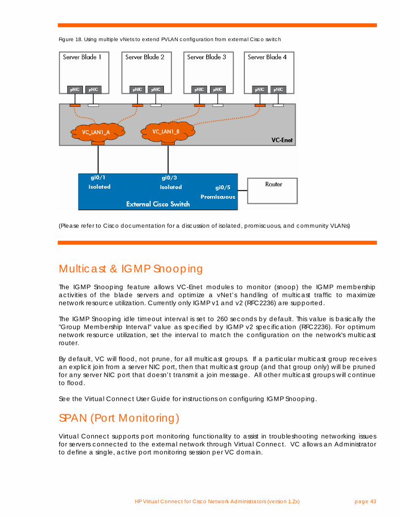
HP Virtual Connect for Cisco Network Administrators (version 1.2x) page 43
Figure 18. Using multiple vNets to extend PVLAN configuration from external Cisco switch
(Please refer to Cisco documentation for a discussion of isolated, promiscuous, and community VLANs)
Multicast & IGMP Snooping The IGMP Snooping feature allows VC-Enet modules to monitor (snoop) the IGMP membership activities of the blade servers and optimize a vNet’s handling of multicast traffic to maximize network resource utilization. Currently only IGMP v1 and v2 (RFC2236) are supported. The IGMP Snooping idle timeout interval is set to 260 seconds by default. This value is basically the "Group Membership Interval" value as specified by IGMP v2 specification (RFC2236). For optimum network resource utilization, set the interval to match the configuration on the network's multicast router. By default, VC will flood, not prune, for all multicast groups. If a particular multicast group receives an explicit join from a server NIC port, then that multicast group (and that group only) will be pruned for any server NIC port that doesn’t transmit a join message. All other multicast groups will continue to flood. See the Virtual Connect User Guide for instructions on configuring IGMP Snooping.
SPAN (Port Monitoring) Virtual Connect supports port monitoring functionality to assist in troubleshooting networking issues for servers connected to the external network through Virtual Connect. VC allows an Administrator to define a single, active port monitoring session per VC domain.
HP Virtual Connect for Cisco Network Administrators (version 1.2x) page 44
The monitor session must be configured with at least one ‘monitored port’ and a single ‘analyzer port’. The ‘monitor port’ list is the list of server downlinks whose traffic will be mirrored. The ‘analyzer port’ is the VC uplink port that the network analyzer is connected to. VC will mirror the traffic from the monitored ports to the analyzer port. A Port Monitoring session can mirror the traffic for up to 16 server downlinks to the analyzer port. Any VC uplink can be defined as the analyzer port and any server downlinks can be selected as the monitored port. There is no VC Ethernet module dependency. Lastly, the Administrator can choose the direction of the traffic to mirror – to the server, from the server, or both.
Logging Virtual Connect provides a local system log that records VC domain events and timestamps. The local system log is not editable and does not permit manual clearing (for security purposes). The log is circular and once the buffer is full, older entries are removed.
Centralized User Access Control (LDAP) In the current version of VC firmware, TACACS+ and RADIUS are not supported for centralized user access control. VC currently only supports Lightweight Directory Access Protocol (LDAP). Please consult the Virtual Connect User Guide for LDAP implementation details.
Cisco Discovery Protocol (CDP) Cisco Discovery Protocol (CDP) is a Cisco proprietary protocol used to exchange device identity and capability information between two directly connected Cisco devices. CDP allows each Cisco device to display, for the administrator, a table showing the identity and capability of other directly connected Cisco devices. One of the primary uses of this information is for troubleshooting purposes. Virtual Connect does not support CDP. VC does support the industry standard protocol called Link Layer Discovery Protocol (LLDP) by default. LLDP is functionally equivalent to CDP, although the two protocols are not compatible. Many Cisco switches support LLDP. The global configuration command “lldp run” and the interface commands “lldp transmit” and “lldp receive” are used to enable LLDP on a Cisco switch that supports the protocol. The exec command “show lldp neighbors” displays LLDP neighbor information to the Cisco switch console. Virtual Connect provides the LLDP neighbor information for each VC uplink at the bottom of the statistics page for each port.
HP Virtual Connect for Cisco Network Administrators (version 1.2x) page 45
Additional Resources HP Services: www.hp.com/go/bladesystem/services BladeSystem Solutions: www.hp.com/go/bladesystem/solutions Virtual Connect Cookbook: www.hp.com/go/bladeconnect (see the Virtual Connect Interest Group) Virtual Connect Documentation: www.hp.com/go/bladesystem/documentation Virtual Connect Firmware: www.hp.com/go/bladesystemupdates HP NIC Teaming for Windows Whitepaper: ftp://ftp.compaq.com/pub/products/servers/networking/TeamingWP.pdf
About the Author M. Sean McGee, CCIE #18040, is the senior network architect for the HP BladeSystem Engineering division. Sean began his career at HP 10 years ago when he joined the Networking Products Division supporting switching and routing products in the 3rd Level support group. Over time, he focused his expertise on data center networking technologies and has spent the last several years in HP engineering groups responsible for HP ProLiant NICs, HP NIC Teaming, HP BladeSystem Ethernet switch architecture, and HP BladeSystem Virtual Connect development. As a member of the HP BladeSystem Engineering division, Sean works with various engineering groups as an internal networking technology consultant for new products, as a technical trainer to customers, partners, and HP Field Engineers, and as a network design consultant to many HP customers deploying HP BladeSystem products.
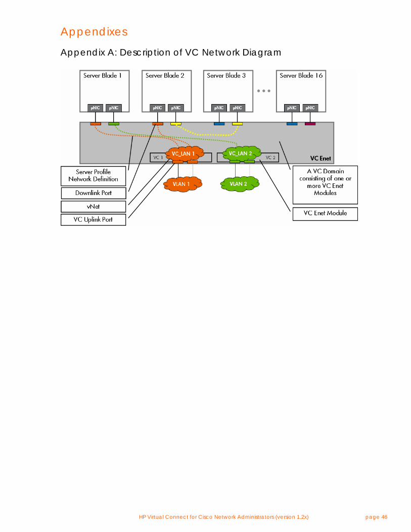
HP Virtual Connect for Cisco Network Administrators (version 1.2x) page 46
Appendixes
Appendix A: Description of VC Network Diagram
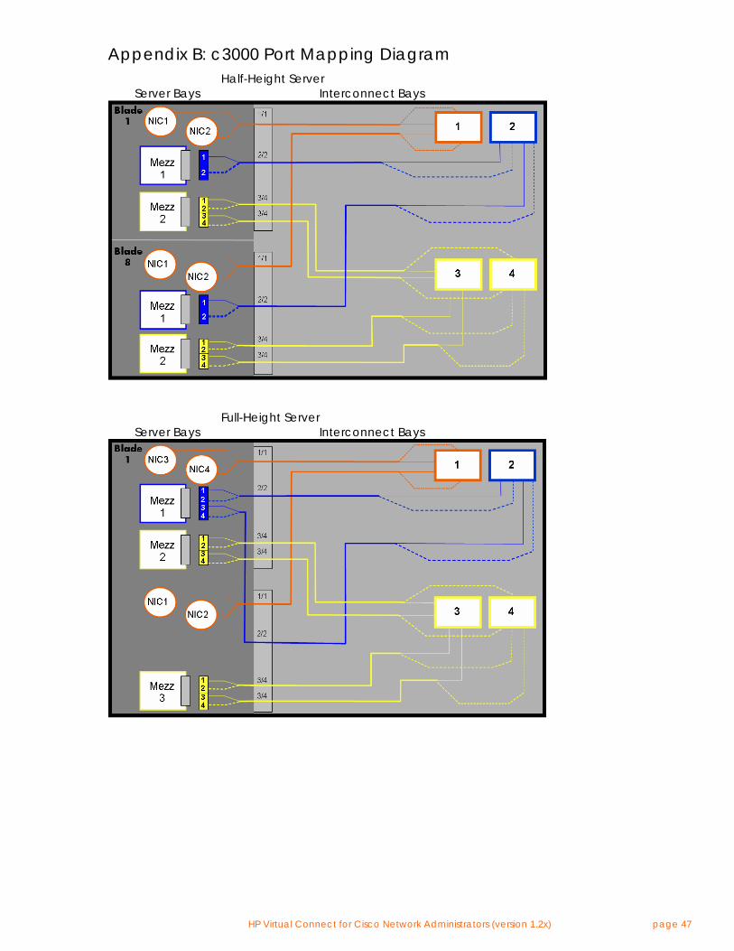
HP Virtual Connect for Cisco Network Administrators (version 1.2x) page 47
Appendix B: c3000 Port Mapping Diagram Half-Height Server Server Bays Interconnect Bays
Full-Height Server Server Bays Interconnect Bays
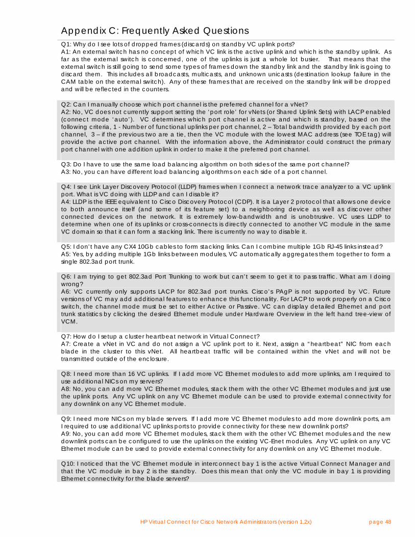
HP Virtual Connect for Cisco Network Administrators (version 1.2x) page 48
Appendix C: Frequently Asked Questions Q1: Why do I see lots of dropped frames (discards) on standby VC uplink ports? A1: An external switch has no concept of which VC link is the active uplink and which is the standby uplink. As far as the external switch is concerned, one of the uplinks is just a whole lot busier. That means that the external switch is still going to send some types of frames down the standby link and the standby link is going to discard them. This includes all broadcasts, multicasts, and unknown unicasts (destination lookup failure in the CAM table on the external switch). Any of these frames that are received on the standby link will be dropped and will be reflected in the counters. Q2: Can I manually choose which port channel is the preferred channel for a vNet? A2: No, VC does not currently support setting the ‘port role’ for vNets (or Shared Uplink Sets) with LACP enabled (connect mode ‘auto’). VC determines which port channel is active and which is standby, based on the following criteria, 1 - Number of functional uplinks per port channel, 2 – Total bandwidth provided by each port channel, 3 – if the previous two are a tie, then the VC module with the lowest MAC address (see TOE tag) will provide the active port channel. With the information above, the Administrator could construct the primary port channel with one addition uplink in order to make it the preferred port channel. Q3: Do I have to use the same load balancing algorithm on both sides of the same port channel? A3: No, you can have different load balancing algorithms on each side of a port channel. Q4: I see Link Layer Discovery Protocol (LLDP) frames when I connect a network trace analyzer to a VC uplink port. What is VC doing with LLDP and can I disable it? A4: LLDP is the IEEE equivalent to Cisco Discovery Protocol (CDP). It is a Layer 2 protocol that allows one device to both announce itself (and some of its feature set) to a neighboring device as well as discover other connected devices on the network. It is extremely low-bandwidth and is unobtrusive. VC uses LLDP to determine when one of its uplinks or cross-connects is directly connected to another VC module in the same VC domain so that it can form a stacking link. There is currently no way to disable it. Q5: I don’t have any CX4 10Gb cables to form stacking links. Can I combine multiple 1Gb RJ-45 links instead? A5: Yes, by adding multiple 1Gb links between modules, VC automatically aggregates them together to form a single 802.3ad port trunk. Q6: I am trying to get 802.3ad Port Trunking to work but can’t seem to get it to pass traffic. What am I doing wrong? A6: VC currently only supports LACP for 802.3ad port trunks. Cisco’s PAgP is not supported by VC. Future versions of VC may add additional features to enhance this functionality. For LACP to work properly on a Cisco switch, the channel mode must be set to either Active or Passive. VC can display detailed Ethernet and port trunk statistics by clicking the desired Ethernet module under Hardware Overview in the left hand tree-view of VCM. Q7: How do I setup a cluster heartbeat network in Virtual Connect? A7: Create a vNet in VC and do not assign a VC uplink port to it. Next, assign a “heartbeat” NIC from each blade in the cluster to this vNet. All heartbeat traffic will be contained within the vNet and will not be transmitted outside of the enclosure. Q8: I need more than 16 VC uplinks. If I add more VC Ethernet modules to add more uplinks, am I required to use additional NICs on my servers? A8: No, you can add more VC Ethernet modules, stack them with the other VC Ethernet modules and just use the uplink ports. Any VC uplink on any VC Ethernet module can be used to provide external connectivity for any downlink on any VC Ethernet module. Q9: I need more NICs on my blade servers. If I add more VC Ethernet modules to add more downlink ports, am I required to use additional VC uplinks ports to provide connectivity for these new downlink ports? A9: No, you can add more VC Ethernet modules, stack them with the other VC Ethernet modules and the new downlink ports can be configured to use the uplinks on the existing VC-Enet modules. Any VC uplink on any VC Ethernet module can be used to provide external connectivity for any downlink on any VC Ethernet module. Q10: I noticed that the VC Ethernet module in interconnect bay 1 is the active Virtual Connect Manager and that the VC module in bay 2 is the standby. Does this mean that only the VC module in bay 1 is providing Ethernet connectivity for the blade servers?
HP Virtual Connect for Cisco Network Administrators (version 1.2x) page 49
A10: No. Regardless of which VC module is running the active Virtual Connect Manager, all VC modules can be used simultaneously to provide network connectivity. Q11: Does VC support iSCSI? A11: Yes VC is compatible with iSCSI. Since VC is a layer 2 device and iSCSI is an upper layer protocol, above TCP/IP, VC does not implement any features specific to iSCSI. However, VC can provide network connectivity for a server running iSCSI just like any other protocol. Q12: Why are failovers taking longer than expected to restore connectivity for the blade servers (taking 20 seconds or longer)? A12: Make sure the upstream Cisco switch ports connected to the VC uplink ports are configured with PortFast enabled (“spanning-tree portfast” or “spanning-tree portfast trunk”) Q13: Does VC interact with STP on my network? A13: No. VC uplink ports look just like server NIC ports (ex. Physical NIC ports on an ESX server) and VC does not support STP on the VC uplink ports. Q14: Should I expect BPDUs to be sent from the VC uplink ports to my external Cisco switch ports? A14: No. VC uplink ports do not transmit BPDUs. Q15: Can I extend any of my L3 routing protocols through the VC domain? A15: Since VC is a layer 2 device, it does not support any routing protocols. However, layer 3 routing protocols such as OSPF, RIP, RIP2, etc. can be used on the servers and operate transparently through VC. Q16: Can I configure transmit and receive load balancing NIC teaming with full redundancy throughout the VC domain? A16: Yes, only if you are using our Integrity blades with INP for Windows/Linux, APA for HP-UX, or Smart Load Balancing in Linux on x86. There are currently no solutions for Windows on x86. Q17: Can I mix VC 1/10 Gb-F and VC 1/10Gb in the same enclosure? A17: yep. great way to increase bandwidth while further minimizing cable and port usage Q18: Does VC support VMware and other OSs that support host-based VLAN tagging? A18: Yes. See appropriate sections above. Q19: Can I use third party branded SFPs and XFPs in a VC 1/10 Gb-F module? A19: No, only HP branded SFP and XFP modules are supported. Q20: Will upgrading the VC firmware require an outage? A20: In general, HP recommends upgrading VC firmware during a scheduled maintenance window. However, VC is able to perform a rolling, non-intrusive upgrade of all modules so long as redundancy is configured throughout the solution. Q21: How fast should I expect a failed VC uplink port to failover to a standby VC uplink port? A21: 5 seconds or less for an optimized configuration Q22: How fast should I expect a port channel (LAG) to failover? A22: 5 seconds or less for an optimized configuration. Q23: How fast should I expect my teamed NICs to failover when a vNet fails over between uplinks? A23: 5 seconds or less for an optimized configuration. Q24: Can I connect VC-Enet’s XFP ports to XENPACK or X2 ports on a Cisco switch? A24: Cisco states that XENPACK, X2, and XFP modules are compatible if using the same port type. Since VC only supports 10GB-LR and 10GB-SR, Virtual Connect should be compatible with XENPACK, X2, and XFP modules from Cisco as long as they are using 10GBASE-LR or 10GBASE-SR modules. Since Cisco supports several port types, several transceiver types, and many different interface modules for their switches, HP does not test every combination. http://www.cisco.com/en/US/prod/collateral/modules/ps5455/prod_brochure0900aecd8034bba6.pdf Q25: Is Virtual Connect compatible with layer 3 protocols other than IP? For instance, does VC support IPv6,
HP Virtual Connect for Cisco Network Administrators (version 1.2x) page 50
IPX, AppleTalk, etc.? A25: Virtual Connect only supports IP (IPv4) on its management interfaces (Web, SSH CLI, or SNMP). In reference to Virtual Connect’s bridging functionality, VC supports any layer 3 or higher protocol in use on blade servers. Since Virtual Connect is a layer 2 device, it is layer 3 protocol agnostic. Meaning, the blade servers can communicate through VC using any upper layer protocol (e.g. IPv4, IPv6, IPX, AppleTalk, etc.) that’s carried within an Ethernet frame. Q26: Does Virtual Connect support jumbo frames? A26: Yes, VC-Enet supports Ethernet frames sizes up to 9216 bytes. Q27: Does Virtual Connect support EtherChannel\802.3ad\SLB on the downlinks to the server NICs? Can I use LACP port trunking on the server NICs connected to Virtual Connect? A27: No, Virtual Connect does not support EtherChannel\802.3ad on the downlinks to server NIC ports.
© 2008 Hewlett-Packard Development Company, L.P. The information contained herein is subject to change without notice. The only warranties for HP products and services are set forth in the express warranty statements accompanying such products and services. Nothing herein should be construed as constituting an additional warranty. HP shall not be liable for technical or editorial errors or omissions contained herein.
VMware and VMware ESX server is a trademark or registered trademark of VMware, INC. or its subsidiaries in the United States and other countries.
Cisco and EtherChannel are trademarks or registered trademarks of Cisco Systems, Inc. or its subsidiaries in the United States and other countries.
486216-001, February 2008