Embed Size (px)
Citation preview
a
HPUSB, USB, and HPPCI Emulators User’s Guide
Revision 3.2, July 2012
Part Number 82-000760-01
Analog Devices, Inc.One Technology WayNorwood, Mass. 02062-9106

Copyright Information© 2012 Analog Devices, Inc., ALL RIGHTS RESERVED. This docu-ment may not be reproduced in any form without prior, express written consent from Analog Devices, Inc.
Printed in the USA.
DisclaimerAnalog Devices, Inc. reserves the right to make changes to or to discon-tinue any product or service identified in this publication without notice.
Analog Devices assumes no liability for Analog Devices applications assis-tance, customer product design, customer software performance, or infringement of patents or services described herein. In addition, Analog Devices shall not be held liable for special, collateral, incidental or conse-quential damages in connection with or arising out of the furnishing, performance, or use of this product.
Analog Devices products are not intended for use in life-support applica-tions, devices, or systems. Use of an Analog Devices product in such applications without the written consent of the appropriate Analog Devices officer is prohibited.
Users are restricted from copying, modifying, distributing, reverse engi-neering and reverse assembling or reverse compiling the Analog Devices emulator operational software (one copy may be made for back-up purposes only).
Trademark and Service Mark NoticeThe Analog Devices logo, Blackfin, CrossCore, EngineerZone, EZ-Board, EZ-KIT Lite, SHARC, and VisualDSP++ are registered trademarks of Analog Devices, Inc.
All other brand and product names are trademarks or service marks of their respective owners.
Regulatory Compliance The USB- and PCI-based emulators are designed to be used solely in a laboratory environment. The emulators are not intended for use as a con-sumer end product or as a portion of a consumer end product. The emulator board is an open system design which does not include a shielded enclosure and therefore may cause interference to other electrical devices in close proximity. This board should not be used in or near any medical equipment or RF devices.
The USB- and PCI-based emulators have been certified to comply with the essential requirements of the European EMC directive 2004/108/EC and therefore carries the “CE” mark.
The USB- and PCI-based emulators have been appended to Analog Devices, Inc. EMC Technical File (EMC TF) referenced DSPTOOLS1, issue 2, dated June 4, 2008 and were declared CE compliant by an appointed Notified Body (No.0673) as listed below.
Notified Body Statement of Compliance: Z600ANA1.015 and Z600ANA1.014 dated September 30, 2003.
Issued by: Technology International (Europe) Limited 56 Shrivenham Hundred Business Park Shrivenham, Swindon, SN6 8TY, UK
The USB- and PCI-based emulators contain ESD (electrostatic discharge) sensitive devices. Electrostatic charges readily accumulate on the human body and equipment and can discharge without detection. Permanent damage may occur on devices subjected to high-energy discharges. Proper ESD precautions are recommended to avoid performance degradation or loss of functionality. Store unused emulators in the protective shipping package.
HPUSB, USB, and HPPCI Emulators User’s Guide v
CONTENTS
PREFACE
Purpose of This Manual ................................................................ ix
Intended Audience ........................................................................ ix
Manual Contents .......................................................................... ix
Technical Support .......................................................................... x
Product Information ..................................................................... xi
Analog Devices Web Site ......................................................... xi
EngineerZone ......................................................................... xii
Notation Conventions .................................................................. xii
GETTING STARTED
Contents of Emulator Package ....................................................... 1-2
PC Configuration ......................................................................... 1-2
USB- and PCI-based Emulator Installation Tasks ........................... 1-3
Installing a USB-Based Emulator ............................................. 1-3
Installing a PCI-Based Emulator .............................................. 1-4
Verifying Driver Installation and Attaching to an Emulation Target ................................................................................... 1-5
Applying Power to the Emulator .............................................. 1-6
Configurator Software ................................................................... 1-7
Contents
vi HPUSB, USB, and HPPCI Emulators User’s Guide
JTAG Frequency Selection ............................................................ 1-8
HPPCI JTAG I/O Voltage Detection .......................................... 1-11
HPUSB/USB Legacy Mode ................................................... 1-11
HPPCI-ICE Legacy/Auto Detection Mode ............................ 1-12
Legacy Mode (Factory Default Setting) .................................. 1-13
Auto Detection Mode ........................................................... 1-14
Troubleshooting and Warranty .................................................... 1-16
HARDWARE DESCRIPTION
LEDs ........................................................................................... 2-1
HPUSB-ICE/USB-ICE LEDs ................................................. 2-1
HPPCI-ICE LEDs .................................................................. 2-2
Pod LEDs ............................................................................... 2-2
Board LEDs ............................................................................ 2-4
Custom Processor Boards .............................................................. 2-5
HPPCI-ICE ................................................................................. 2-5
SUPPORT
Technical Support ......................................................................... 3-1
Quality Assurance ......................................................................... 3-2
REFERENCES
INDEX
HPUSB, USB, and HPPCI Emulators User’s Guide vii
PREFACE
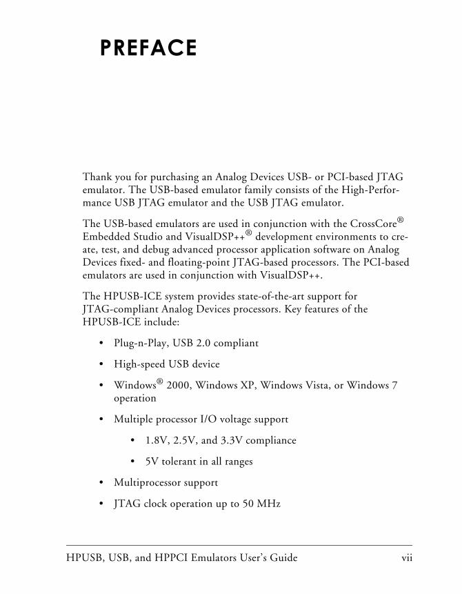
Thank you for purchasing an Analog Devices USB- or PCI-based JTAG emulator. The USB-based emulator family consists of the High-Perfor-mance USB JTAG emulator and the USB JTAG emulator.
The USB-based emulators are used in conjunction with the CrossCore® Embedded Studio and VisualDSP++® development environments to cre-ate, test, and debug advanced processor application software on Analog Devices fixed- and floating-point JTAG-based processors. The PCI-based emulators are used in conjunction with VisualDSP++.
The HPUSB-ICE system provides state-of-the-art support for JTAG-compliant Analog Devices processors. Key features of the HPUSB-ICE include:
• Plug-n-Play, USB 2.0 compliant
• High-speed USB device
• Windows® 2000, Windows XP, Windows Vista, or Windows 7 operation
• Multiple processor I/O voltage support
• 1.8V, 2.5V, and 3.3V compliance
• 5V tolerant in all ranges
• Multiprocessor support
• JTAG clock operation up to 50 MHz
viii HPUSB, USB, and HPPCI Emulators User’s Guide
The HPPCI-ICE system provides state-of-the-art support for JTAG-compliant Analog Devices processors. Key features of the HPPCI-ICE include:
• Plug-n-Play, PCI 2.2 compliant
• Windows 2000, Windows XP, Windows Vista, or Windows 7 operation
• Multiple processor I/O voltage support:
• 1.8V, 2.5V, and 3.3V compliance
• 5V tolerant in all ranges
• Multiprocessor support
• JTAG clock operation up to 50 MHz
The JTAG clock frequency is dependent on the delay characteris-tics of the JTAG interface and processor on the target board.
The USB-ICE system provides state-of-the-art support for selected processors. Key features of the USB-ICE include:
• Plug-n-Play, USB 2.0 compliant
• High-speed USB device
• Windows 2000, Windows XP, Windows Vista, or Windows 7 operation
• Multiple processor I/O voltage support:
• 1.8V, 2.5V, and 3.3V compliance
• 5V tolerant in all ranges
• Multiprocessor support
• JTAG clock operation up to 50 MHz
HPUSB, USB, and HPPCI Emulators User’s Guide ix
Preface
Analog Devices carries a wide range of in-circuit emulation products. To learn more about Analog Devices emulators, go to: http://www.analog.com/en/processors-dsp/software-and-refer-
ence-designs/content/tools_product_overview/fca.html.
Purpose of This ManualThe HPUSB, USB, and HPPCI Emulators User’s Guide provides directions for installing the high-performance USB-ICE, USB ICE, and high-perfor-mance HPPCI-ICE hardware and software on your PC. The manual also describes how to configure and use the components of the USB- and PCI-based emulators.
Intended AudienceThis manual is intended to help the customer understand the features and operation of the HPUSB-ICE, HPPCI-ICE, and USB-ICE so they start using CrossCore Embedded Studio or VisualDSP++.
Manual ContentsThe manual consists of:
• Chapter 1, “Getting Started” on page 1-1Provides software and hardware installation procedures, PC system requirements, and basic board information.
• Chapter 2, “Hardware Description” on page 2-1Provides information on hardware aspects of the USB-based emulators.

Technical Support
x HPUSB, USB, and HPPCI Emulators User’s Guide
• Chapter 3, “Support” on page 3-1Provides technical support contact information.
• Chapter 4, “References” on page 4-1Provides information about different resources available for devel-oping an application based on an Analog Devices processor.
Technical SupportYou can reach Analog Devices processors and DSP technical support in the following ways:
• Post your questions in the processors and DSP support community at EngineerZone®:http://ez.analog.com/community/dsp
• Submit your questions to technical support directly at:http://www.analog.com/support
• E-mail your questions about processors, DSPs, and tools develop-ment software from CrossCore Embedded Studio or VisualDSP++®:
Choose Help > Email Support. This creates an e-mail [email protected] and automatically attaches your CrossCore Embedded Studio or VisualDSP++ version infor-mation and license.dat file.
• E-mail your questions about processors and processor applications to: [email protected] [email protected] (Greater China support)
• In the USA only, call 1-800-ANALOGD (1-800-262-5643)
HPUSB, USB, and HPPCI Emulators User’s Guide xi
Preface
• Contact your Analog Devices sales office or authorized distributor. Locate one at:www.analog.com/adi-sales
• Send questions by mail to:Processors and DSP Technical SupportAnalog Devices, Inc.Three Technology WayP.O. Box 9106Norwood, MA 02062-9106USA
Product InformationProduct information can be obtained from the Analog Devices Web site and the CCES online help.
Analog Devices Web SiteThe Analog Devices Web site, www.analog.com, provides information about a broad range of products—analog integrated circuits, amplifiers, converters, and digital signal processors.
To access a complete technical library for each processor family, go to http://www.analog.com/processors/technical_library. The manuals selection opens a list of current manuals related to the product as well as a link to the previous revisions of the manuals. When locating your manual title, note a possible errata check mark next to the title that leads to the current correction report against the manual.
Also note, myAnalog is a free feature of the Analog Devices Web site that allows customization of a Web page to display only the latest information about products you are interested in. You can choose to receive weekly e-mail notifications containing updates to the Web pages that meet your
Notation Conventions
xii HPUSB, USB, and HPPCI Emulators User’s Guide
interests, including documentation errata against all manuals. myAnalog provides access to books, application notes, data sheets, code examples, and more.
Visit myAnalog to sign up. If you are a registered user, just log on. Your user name is your e-mail address.
EngineerZoneEngineerZone is a technical support forum from Analog Devices. It allows you direct access to ADI technical support engineers. You can search FAQs and technical information to get quick answers to your embedded processing and DSP design questions.
Use EngineerZone to connect with other DSP developers who face similar design challenges. You can also use this open forum to share knowledge and collaborate with the ADI support team and your peers. Visit http://ez.analog.com to sign up.
Notation ConventionsText conventions used in this manual are identified and described as follows.
Example Description
Close command (File menu)
Titles in in bold style reference sections indicate the location of an item within the CrossCore Embedded Studio’s menu system (for example, the Close command appears on the File menu).
{this | that} Alternative required items in syntax descriptions appear within curly brackets and separated by vertical bars; read the example as this or that. One or the other is required.
[this | that] Optional items in syntax descriptions appear within brackets and sepa-rated by vertical bars; read the example as an optional this or that.
HPUSB, USB, and HPPCI Emulators User’s Guide xiii
Preface
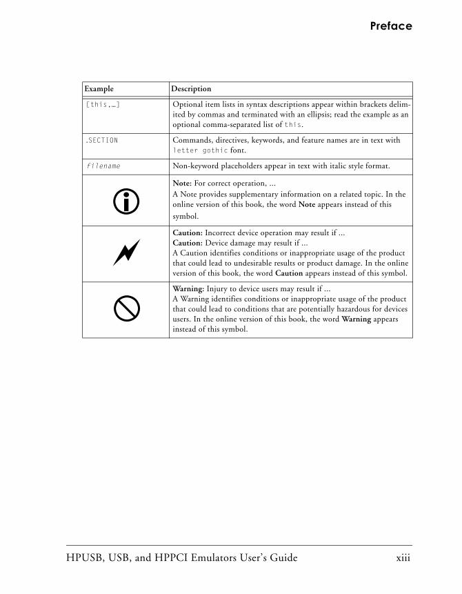
[this,…] Optional item lists in syntax descriptions appear within brackets delim-ited by commas and terminated with an ellipsis; read the example as an optional comma-separated list of this.
.SECTION Commands, directives, keywords, and feature names are in text with letter gothic font.
filename Non-keyword placeholders appear in text with italic style format.
Note: For correct operation, ...A Note provides supplementary information on a related topic. In the online version of this book, the word Note appears instead of this
symbol.
Caution: Incorrect device operation may result if ...Caution: Device damage may result if ... A Caution identifies conditions or inappropriate usage of the product that could lead to undesirable results or product damage. In the online version of this book, the word Caution appears instead of this symbol.
Warning: Injury to device users may result if ... A Warning identifies conditions or inappropriate usage of the product that could lead to conditions that are potentially hazardous for devices users. In the online version of this book, the word Warning appears instead of this symbol.
Example Description
Notation Conventions
xiv HPUSB, USB, and HPPCI Emulators User’s Guide
HPUSB, USB, and HPPCI Emulators User’s Guide 1-1
1 GETTING STARTED
This chapter provides the information needed to begin using Analog Devices USB- and PCI-based emulators.
Analog Devices emulators are not intended to be used in a production environment.
This chapter includes the following sections.
• “Contents of Emulator Package” on page 1-2Provides a list of components shipped with USB- and PCI-based emulators.
• “PC Configuration” on page 1-2Describes the minimal PC requirements.
• “USB- and PCI-based Emulator Installation Tasks” on page 1-3Provides a step-by-step procedure for setting up the emulator hard-ware and software.
• “Configurator Software” on page 1-7Describes the target configurator utility.
• “JTAG Frequency Selection” on page 1-8Provides information on JTAG frequency limitations.
Contents of Emulator Package
1-2 HPUSB, USB, and HPPCI Emulators User’s Guide
• “HPPCI JTAG I/O Voltage Detection” on page 1-11Describes the JTAG I/O voltage detection feature of HPPCI emulators.
• “Troubleshooting and Warranty” on page 1-16Points to an Engineer-to-Engineer Note for troubleshooting advice and warranty information.
Contents of Emulator PackageYour USB-based emulator package contains the following items.
• HPUSB-ICE or USB-ICE assembly
• 5-volt power supply
• 3-meter USB type-A to mini-B cable
Your High-Performance PCI emulator package contains the following items.
• HPPCI-ICE or JTAG daughter card
• HPPCI-ICE pod assembly
PC ConfigurationFor correct operation of a USB- or PCI-based emulator, your PC must meet the minimum requirements.
HPUSB, USB, and HPPCI Emulators User’s Guide 1-3
Getting Started
USB- and PCI-based Emulator Installation Tasks
Perform the following tasks to install your USB- or PCI-based emulator safely. Follow the instructions in presented order to ensure correct opera-tion of your software and hardware.
1. Installing a USB-Based Emulator or Installing a PCI-Based Emulator
2. Verifying Driver Installation and Attaching to an Emulation Target
3. Applying Power to the Emulator
Installing a USB-Based Emulator1. Install CCES or VisualDSP++ on your computer. The installation
includes a USB driver required for your USB-based emulator. If CCES or VisualDSP++ is installed already, you do not need to install it again.
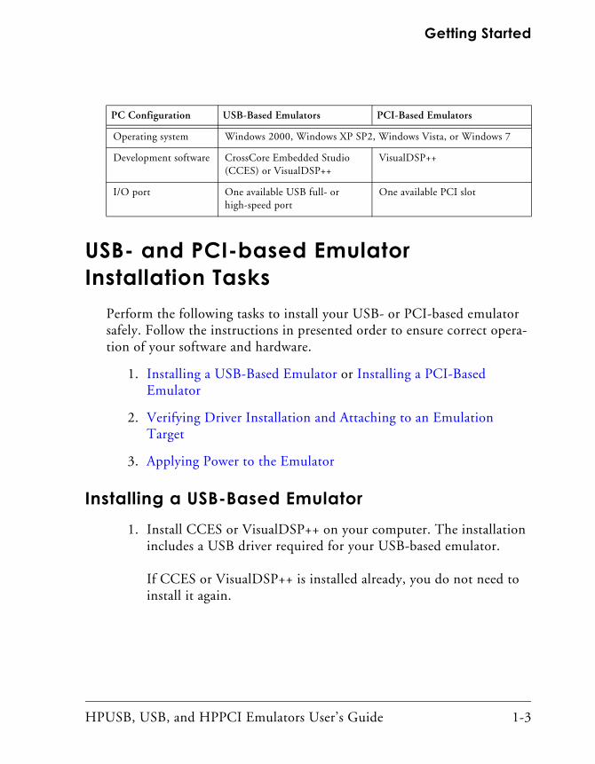
PC Configuration USB-Based Emulators PCI-Based Emulators
Operating system Windows 2000, Windows XP SP2, Windows Vista, or Windows 7
Development software CrossCore Embedded Studio (CCES) or VisualDSP++
VisualDSP++
I/O port One available USB full- or high-speed port
One available PCI slot
USB- and PCI-based Emulator Installation Tasks
1-4 HPUSB, USB, and HPPCI Emulators User’s Guide
Note: If you connect the emulator first (before installing CCES or VisualDSP++) to the PC, the Windows driver wizard will not find the drivers for the emulator.
2. Connect one side of the provided USB cable to the USB assembly of the emulator and the other side to an open USB port of your computer.
Verifying Driver Installation and Attaching to an Emulation Target is next.
Installing a PCI-Based Emulator
The driver must be installed before you start the HPPCI-ICE for the first time.
1. Install the HPPCI-ICE hardware. For instructions on installing a PCI card into your computer, consult documentation provided by the computer manufacturer.
2. Install VisualDSP++. VisualDSP++ includes the HPPCI driver needed for your PCI emulation hardware. Refer to the Visu-alDSP++ Installation Quick Reference Card for details.
Verifying Driver Installation and Attaching to an Emulation Target is next.
HPUSB, USB, and HPPCI Emulators User’s Guide 1-5
Getting Started
Verifying Driver Installation and Attaching to an Emulation Target
Before using your USB- or PCI-based emulator, verify that the driver software is installed properly.
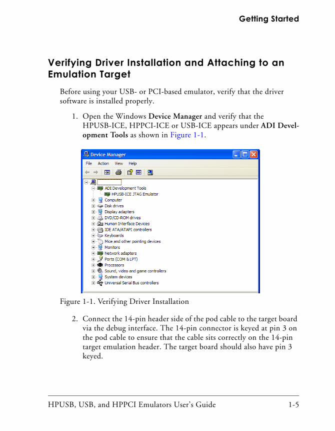
1. Open the Windows Device Manager and verify that the HPUSB-ICE, HPPCI-ICE or USB-ICE appears under ADI Devel-opment Tools as shown in Figure 1-1.
2. Connect the 14-pin header side of the pod cable to the target board via the debug interface. The 14-pin connector is keyed at pin 3 on the pod cable to ensure that the cable sits correctly on the 14-pin target emulation header. The target board should also have pin 3 keyed.
Figure 1-1. Verifying Driver Installation
USB- and PCI-based Emulator Installation Tasks
1-6 HPUSB, USB, and HPPCI Emulators User’s Guide
Do not connect or disconnect a USB emulator JTAG header, whether powered up or not, to/from a powered target.
Applying Power to the Emulator is next.
Applying Power to the EmulatorThe final step is to power up the emulator.
The following procedures apply to HP-USB and USB emulators only.
Powering up a USB-based emulator:
1. Apply power to target board.
2. Apply power to the emulator
3. If the emulator is not connected to the PC, connect the devices with the USB cable as described in Verifying Driver Installation and Attaching to an Emulation Target.
4. Invoke CrossCore Embedded Studio or VisualDSP++.
Powering down a USB-based emulator:
1. Shut down (exit) CrossCore Embedded Studio or VisualDSP++.
2. Disconnect the USB cable from the emulator and PC.
3. Power down the emulator.
4. Power down the target board.
If the emulator has an “Enable/Power” LED, the power LED lights green when power is applied. The power LED lights amber when connected to a session or when the ICE Test utility is used.If the emulator has an “Enable” LED only, the LED lights amber
HPUSB, USB, and HPPCI Emulators User’s Guide 1-7
Getting Started
when connected to a session or when the ICE Test utility is used.At all other times, the LED should be off.
For custom processor boards still in design, refer to the Engineer-to-Engi-neer Note, Analog Devices JTAG Emulation Technical Reference (EE-68), available from the Analog Devices Web site. This document is a technical reference for implementing the JTAG interface on your target.
Now the emulator hardware is ready to be used in conjunction with CCES or VisualDSP++ to debug a processor target system. See “Configurator Software”.
Configurator SoftwareCrossCore Embedded Studio and VisualDSP++ development software require a description of your platform (JTAG chain). The platform defini-tion is necessary for the software to communicate with the hardware through the emulator.
The VisualDSP++ and CCES include the target configurator utility to configure and test your emulator hardware. The target configurator pro-vides emulator detection, JTAG I/O voltage selection, and JTAG frequency selection. Use the ICE Test (part of the target configurator) to test the target. If any errors are encountered, the errors are reported imme-diately and the test ends. Each error message recommends a solution to the problem.
Refer to the online help for information about “target configurator”, “JTAG frequency”, and “ICE test”.
JTAG Frequency Selection
1-8 HPUSB, USB, and HPPCI Emulators User’s Guide
JTAG Frequency SelectionUSB-ICE emulators, high-performance PCI-ICE, and high-performance USB-ICE emulators support a JTAG clock operation up to 50 MHz.
Not all frequencies listed above are supported for all processor fam-ilies. The displayed frequencies depend upon the processor family.
There is a relationship between the JTAG frequency and core clock fre-quency of the processor. Typically, the core clock runs at a frequency that is more than 2x the JTAG clock’s frequency. On newer Analog Devices processors, the core clock is a variable that sometimes is set by switches or software.
If the core/JTAG clock relation is not followed, scan failures can prevent the emulator from connecting to the processor.
Use the JTAG Frequency Selection dialog box to test and change the rate at which the JTAG Test Clock signal (TCK) runs. To access the dialog box:
• CrossCore Embedded Studio users choose Target > Settings > JTAG Frequency Selection after launching a debug configuration.
• VisualDSP++ users choose Settings > JTAG Frequency Selection after creating a debug session.
HPUSB, USB, and HPPCI Emulators User’s Guide 1-9
Getting Started
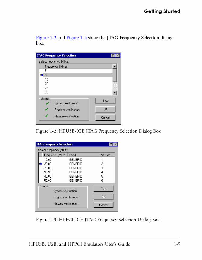
Figure 1-2 and Figure 1-3 show the JTAG Frequency Selection dialog box.
Figure 1-2. HPUSB-ICE JTAG Frequency Selection Dialog Box
Figure 1-3. HPPCI-ICE JTAG Frequency Selection Dialog Box
JTAG Frequency Selection
1-10 HPUSB, USB, and HPPCI Emulators User’s Guide
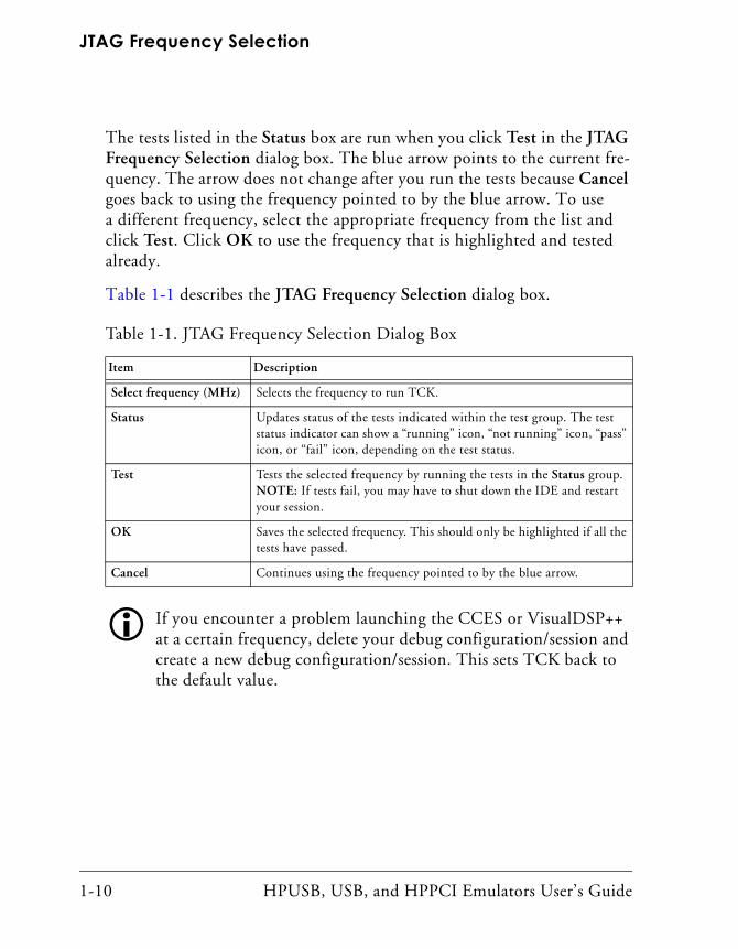
The tests listed in the Status box are run when you click Test in the JTAG Frequency Selection dialog box. The blue arrow points to the current fre-quency. The arrow does not change after you run the tests because Cancel goes back to using the frequency pointed to by the blue arrow. To use a different frequency, select the appropriate frequency from the list and click Test. Click OK to use the frequency that is highlighted and tested already.
Table 1-1 describes the JTAG Frequency Selection dialog box.
If you encounter a problem launching the CCES or VisualDSP++ at a certain frequency, delete your debug configuration/session and create a new debug configuration/session. This sets TCK back to the default value.
Table 1-1. JTAG Frequency Selection Dialog Box
Item Description
Select frequency (MHz) Selects the frequency to run TCK.
Status Updates status of the tests indicated within the test group. The test status indicator can show a “running” icon, “not running” icon, “pass” icon, or “fail” icon, depending on the test status.
Test Tests the selected frequency by running the tests in the Status group. NOTE: If tests fail, you may have to shut down the IDE and restart your session.
OK Saves the selected frequency. This should only be highlighted if all the tests have passed.
Cancel Continues using the frequency pointed to by the blue arrow.
HPUSB, USB, and HPPCI Emulators User’s Guide 1-11
Getting Started
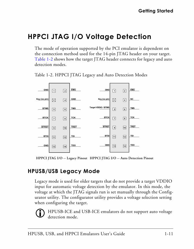
HPPCI JTAG I/O Voltage DetectionThe mode of operation supported by the PCI emulator is dependent on the connection method used for the 14-pin JTAG header on your target. Table 1-2 shows how the target JTAG header connects for legacy and auto detection modes.
HPUSB/USB Legacy ModeLegacy mode is used for older targets that do not provide a target VDDIO input for automatic voltage detection by the emulator. In this mode, the voltage at which the JTAG signals run is set manually through the Config-urator utility. The configurator utility provides a voltage selection setting when configuring the target.
HPUSB-ICE and USB-ICE emulators do not support auto voltage detection mode.
Table 1-2. HPPCI JTAG Legacy and Auto Detection Modes
HPPCI JTAG I/O -- Legacy Pinout HPPCI JTAG I/O -- Auto Detection Pinout
1 2
4
5 6
7 8
9 10
11 12
13 14
GND
Key (no pin)
EMU
GND
TMS
TCK
TRST
TDI
TDOGND
BTMS
BTCK
BTRST
BTDI
1 2
4
5 6
7 8
9 10
11 12
13 14
GND
Key (no pin)
EMU
NC
TMS
TCK
TRST
TDI
TDOGND
Target VDDIO / BTMS
BTCK
BTRST
BTDI
HPPCI JTAG I/O Voltage Detection
1-12 HPUSB, USB, and HPPCI Emulators User’s Guide
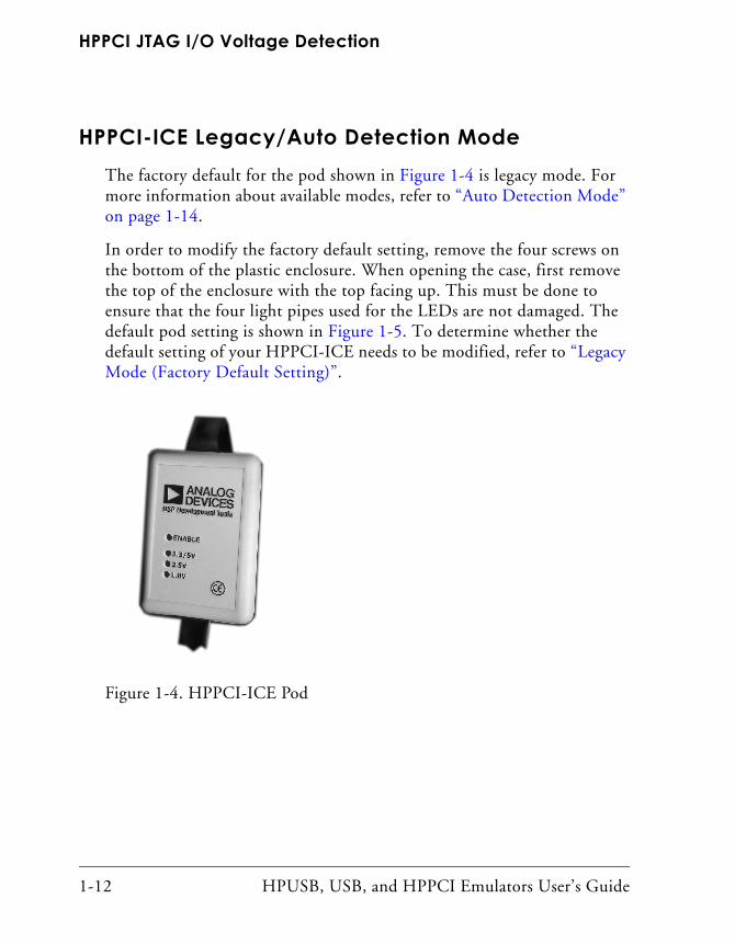
HPPCI-ICE Legacy/Auto Detection ModeThe factory default for the pod shown in Figure 1-4 is legacy mode. For more information about available modes, refer to “Auto Detection Mode” on page 1-14.
In order to modify the factory default setting, remove the four screws on the bottom of the plastic enclosure. When opening the case, first remove the top of the enclosure with the top facing up. This must be done to ensure that the four light pipes used for the LEDs are not damaged. The default pod setting is shown in Figure 1-5. To determine whether the default setting of your HPPCI-ICE needs to be modified, refer to “Legacy Mode (Factory Default Setting)”.
Figure 1-4. HPPCI-ICE Pod
HPUSB, USB, and HPPCI Emulators User’s Guide 1-13
Getting Started
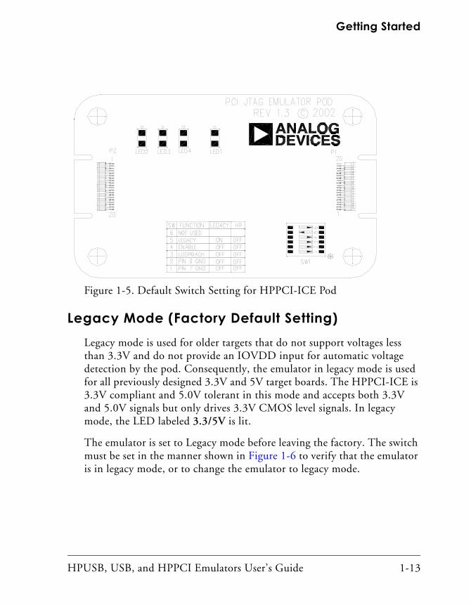
Legacy Mode (Factory Default Setting)Legacy mode is used for older targets that do not support voltages less than 3.3V and do not provide an IOVDD input for automatic voltage detection by the pod. Consequently, the emulator in legacy mode is used for all previously designed 3.3V and 5V target boards. The HPPCI-ICE is 3.3V compliant and 5.0V tolerant in this mode and accepts both 3.3V and 5.0V signals but only drives 3.3V CMOS level signals. In legacy mode, the LED labeled 3.3/5V is lit.
The emulator is set to Legacy mode before leaving the factory. The switch must be set in the manner shown in Figure 1-6 to verify that the emulator is in legacy mode, or to change the emulator to legacy mode.
Figure 1-5. Default Switch Setting for HPPCI-ICE Pod
HPPCI JTAG I/O Voltage Detection
1-14 HPUSB, USB, and HPPCI Emulators User’s Guide
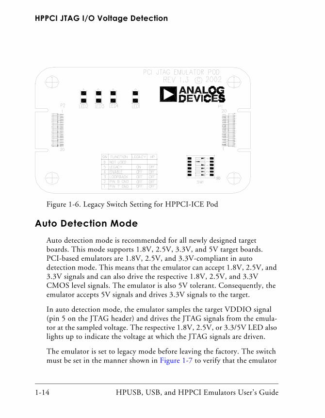
Auto Detection ModeAuto detection mode is recommended for all newly designed target boards. This mode supports 1.8V, 2.5V, 3.3V, and 5V target boards. PCI-based emulators are 1.8V, 2.5V, and 3.3V-compliant in auto detection mode. This means that the emulator can accept 1.8V, 2.5V, and 3.3V signals and can also drive the respective 1.8V, 2.5V, and 3.3V CMOS level signals. The emulator is also 5V tolerant. Consequently, the emulator accepts 5V signals and drives 3.3V signals to the target.
In auto detection mode, the emulator samples the target VDDIO signal (pin 5 on the JTAG header) and drives the JTAG signals from the emula-tor at the sampled voltage. The respective 1.8V, 2.5V, or 3.3/5V LED also lights up to indicate the voltage at which the JTAG signals are driven.
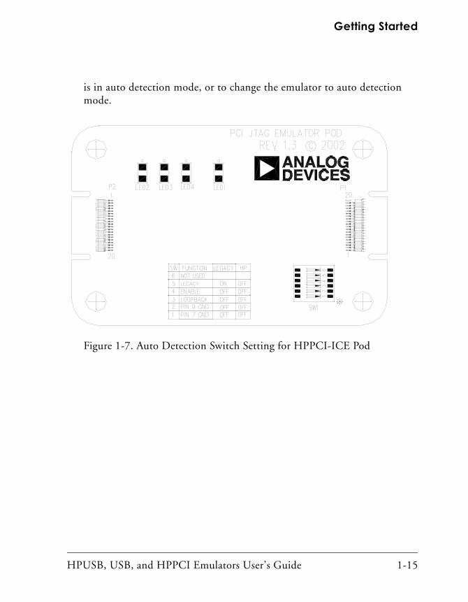
The emulator is set to legacy mode before leaving the factory. The switch must be set in the manner shown in Figure 1-7 to verify that the emulator
Figure 1-6. Legacy Switch Setting for HPPCI-ICE Pod
HPUSB, USB, and HPPCI Emulators User’s Guide 1-15
Getting Started
is in auto detection mode, or to change the emulator to auto detection mode.
Figure 1-7. Auto Detection Switch Setting for HPPCI-ICE Pod

Troubleshooting and Warranty
1-16 HPUSB, USB, and HPPCI Emulators User’s Guide
Troubleshooting and WarrantyTo provide comprehensive troubleshooting advice and warranty information for all emulator and EZ-KIT Lite products, Analog Devices maintains an Engineer-to-Engineer Note. Emulator and EZ-KIT Lite Eval-uation System Troubleshooting Guide (EE-175) is available online at: http://www.analog.com.
This EE-Note can be used to resolve most installation, connection, and software issues affecting the use of Analog Devices in-circuit emulators (ICEs) and EZ-KIT Lite evaluation systems, avoiding the need to return the suspected faulty emulator or EZ-KIT Lite board. Please carry out all troubleshooting steps outlined in this document before contacting Analog Devices Processor Tools Support.
Also included in the EE-Note, complete warranty and return material authorization (RMA) information for emulators and EZ-KIT Lite prod-ucts. In general, emulators less than one year old are within warranty, and repairs within that period are free of charge, but there are some limitations to this warranty coverage. For details, see the note.
HPUSB, USB, and HPPCI Emulators User’s Guide 2-1
2 HARDWARE DESCRIPTION
This chapter describes the hardware design of the USB- and PCI-based emulators.
LEDsThis section describes the following LEDs:
• “HPUSB-ICE/USB-ICE LEDs”
• “HPPCI-ICE LEDs” on page 2-2
• “Pod LEDs” on page 2-2
• “Board LEDs” on page 2-4
HPUSB-ICE/USB-ICE LEDsFour LEDs are located on the enclosure:
• 1.8V LED – Signifies that the ICE drives all signals at 1.8V compliant levels.
• 2.5V LED – Signifies that the ICE drives all signals at 2.5V compliant levels.
LEDs
2-2 HPUSB, USB, and HPPCI Emulators User’s Guide
• 3.3/5V LED – Signifies that the ICE drives all signals at 3.3V compliant levels.
• ENABLE – This LED is amber when the debugger is enabled. This means that the emulator is driving the JTAG signals, and the con-nector must not remove or plug onto a target when the light is amber. When the LED is green, the JTAG signals are not being driven, and it is safe to connect to a target. The green LED indi-cates that the board is powered up but not in emulation mode.
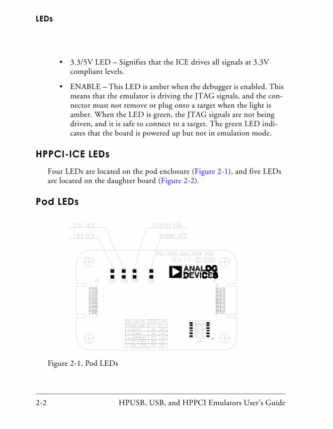
HPPCI-ICE LEDsFour LEDs are located on the pod enclosure (Figure 2-1), and five LEDs are located on the daughter board (Figure 2-2).
Pod LEDs
Figure 2-1. Pod LEDs
HPUSB, USB, and HPPCI Emulators User’s Guide 2-3
Hardware Description
• 1.8V LED – In auto detection mode, this LED signifies that a target VDDIO of 1.8V has been detected on the JTAG header (pin 5) on the processor target board, and the HPPCI-ICE drives all signals at 1.8V compliant levels.
• 2.5V LED – In auto detection mode, this LED signifies that a target VDDIO of 2.5V has been detected on the JTAG header (pin 5) on the processor target board, and the HPPCI-ICE drives all signals at 2.5V compliant levels.
• 3.3/5V LED – In auto detection mode, this LED signifies that a target VDDIO of 3.3V or 5V has been detected on the JTAG header (pin 5) on the processor target board, and the HPPCI-ICE drives all signals at 3.3V compliant levels. In legacy mode, this LED is powered automatically, and pin 5 of the JTAG header on the target board is not used to detect the target VDDIO voltage.
• ENABLE – This LED is turned on when a CrossCore Embedded Studio (CCES) or VisualDSP++ debug session is running. This LED shuts off every time the session is closed. When this LED is off, it signifies all outputs of the pod logic connected to the target have been three-stated. Three-stating the outputs of the pod when the IDE is inactive prevents the target processor from entering an unknown state during the target power up sequencing.
LEDs
2-4 HPUSB, USB, and HPPCI Emulators User’s Guide
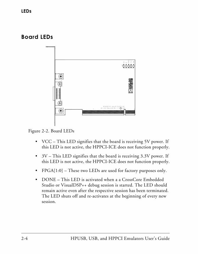
Board LEDs
• VCC – This LED signifies that the board is receiving 5V power. If this LED is not active, the HPPCI-ICE does not function properly.
• 3V – This LED signifies that the board is receiving 3.3V power. If this LED is not active, the HPPCI-ICE does not function properly.
• FPGA[1:0] – These two LEDs are used for factory purposes only.
• DONE – This LED is activated when a a CrossCore Embedded Studio or VisualDSP++ debug session is started. The LED should remain active even after the respective session has been terminated. The LED shuts off and re-activates at the beginning of every new session.
Figure 2-2. Board LEDs
HPUSB, USB, and HPPCI Emulators User’s Guide 2-5
Hardware Description
Custom Processor BoardsWhen designing a custom processor board using Analog Devices processors and DSPs, special care must be taken to ensure that the JTAG interface is designed and laid out correctly. If the board is not designed correctly, communication via the JTAG port may not work. Another side effect may be that the interface works, but you are not able to run at the highest possible JTAG clock frequency. The JTAG clock frequency is dependant on the particular Analog Devices processor, as well as the delay characteristics of the custom processor board.
To ensure that the custom board’s JTAG interface is designed and laid out correctly, refer to Engineer-to-Engineer Note, Analog Devices JTAG Emu-lation Technical Reference (EE-68), available from the Analog Devices Web site. This document is a technical reference for implementing the JTAG interface on your target.
HPPCI-ICEThe HPPCI-ICE consists of a daughter board and a pod cable. The system is compliant with revision 2.2 of the PCI specification and plugs into 5V-only motherboards. It uses only the 5 volts from the PC’s PCI slot. The pod cable consists of a small PCB that has a multi-conductor cable soldered at each end. The multi-conductor cable is constructed with indi-vidual coaxial cables that are encapsulated by shield ground. The PCB in the pod is fully enclosed in a copper-sprayed plastic enclosure. The multi-conductor cables and copper spray reduce system noise and electro-magnetic interference.
HPPCI-ICE
2-6 HPUSB, USB, and HPPCI Emulators User’s Guide
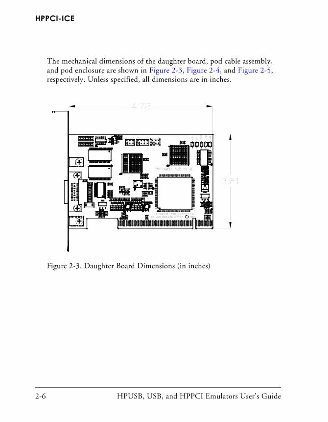
The mechanical dimensions of the daughter board, pod cable assembly, and pod enclosure are shown in Figure 2-3, Figure 2-4, and Figure 2-5, respectively. Unless specified, all dimensions are in inches.
Figure 2-3. Daughter Board Dimensions (in inches)
HPUSB, USB, and HPPCI Emulators User’s Guide 2-7
Hardware Description
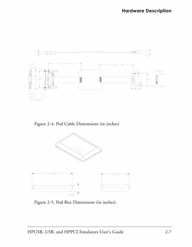
Figure 2-4. Pod Cable Dimensions (in inches)
Figure 2-5. Pod Box Dimensions (in inches)

HPPCI-ICE
2-8 HPUSB, USB, and HPPCI Emulators User’s Guide
HPUSB, USB, and HPPCI Emulators User’s Guide 3-1
3 SUPPORT
Analog Devices provides free technical support.
Technical SupportFor technical support, visit the Analog Devices Worldwide Technical Sup-port page at: http://www.analog.com/support.
From there you can:
• Access the EngineerZone DSP Support Forum where Analog Devices support team members and other designers exchange ideas and answer questions
• Search our vast Knowledge Base containing application notes, data sheets, code examples, manuals, and more
• Contact our Technical Support team directly by filling out the support form
Alternately, you can contact Technical Support directly as follows:
• For tools issues, send a description of the problem by e-mail to [email protected]
• For processor issues, send a description of the problem by e-mail to the Application Engineering group at [email protected]
Quality Assurance
3-2 HPUSB, USB, and HPPCI Emulators User’s Guide
Quality AssuranceAnalog Devices is committed to providing quality products and services. To continually provide this quality, please contact our Quality Assurance Department directly if you have any concerns at (603) 883-2430, Monday through Friday during normal business hours, or via e-mail at [email protected]. Our Quality Assurance manager will listen to your concerns and provide a timely and effective solution.
HPUSB, USB, and HPPCI Emulators User’s Guide 4-1
4 REFERENCES
This section describes documentation resources helpful in your applica-tion development.
• For information on designing the interface between an Analog Devices SHARC processor and the emulation header on your custom processor target board, refer to Engineer-to-Engineer Note, Analog Devices JTAG Emulation Technical Reference (EE-68), available from the Analog Devices Web site.
• For information on the architecture and system interface of the Analog Devices processor, refer to the appropriate Analog Devices processor’s hardware reference manual.
• For processor timing specification and other hardware design information, refer to the appropriate processor’s data sheet.
• For complete information on software development tools (assembler, compiler, linker, and so on), refer to documentation included with CrossCore Embedded Studio or VisualDSP++. This information also is available in the online help and PDF format in the Docs folder.
4-2 HPUSB, USB, and HPPCI Emulators User’s Guide
• For information about your development platform, refer to your operating system manuals and hardware system manuals.
• For information about digital signal processing theory and applications, consult:
• Higgins. Digital Signal Processing In VLSI. Prentice-Hall, 1990.
• Oppenheim and Schafer. Digital Signal Processing. Prentice-Hall, 1975.
HPUSB, USB, and HPPCI Emulators User’s Guide I-1
I INDEX
Numerics1.8V LED, 2-1, 2-32.5V LED, 2-1, 2-33.3/5V LED, 2-2, 2-3
Aassembly, 1-2auto detection mode, 1-14
Bboard LEDs, 2-4
Ccables, 1-2CMOS signals, 1-14Configurator utility, 1-11connecting USB cable, 1-4contents, emulator package, 1-2custom processor boards, 2-5
Ddata sheets, 4-1default setting, 1-12designing custom boards, 2-5Device Manager window, 1-5digital signal processing theory, 4-2documentation resources, 4-1drivers, 1-5
EEE-175, 1-2, 1-16EE-68, 1-7, 2-5, 4-1emulator troubleshooting, 1-2, 1-16enable LED, 2-2, 2-3
Ffactory default setting, 1-12, 1-13frequency, 2-5full/high speed USB port, -viii, 1-3
Hhardware
description, 2-1references, 4-1
high-speed USB device, viiHPPCI-ICE
installation, 1-4JTAG I/O voltage detection, 1-11LEDs, 2-2legacy mode, 1-12mechanical specifications, 2-5voltage support, viii
Iinstallation tasks, 1-3IOVDD input, 1-13I/O voltage, vii, viii
Index
I-2 HPUSB, USB, and HPPCI Emulators User’s Guide
JJTAG
clock frequency, viii, 2-5See also TCK
daughter card, 1-2frequency selection, 1-8header, 1-11, 1-14, 2-5port, 2-5signals, 1-11, 1-14voltage I/O detection, 1-11
JTAG Frequency Selection dialog box, 1-7, 1-10
LLEDs
1.8V LED, 2-1, 2-32.5V LED, 2-1, 2-33.3/5V LED, 2-2, 2-3enable LED, 2-2HPPCI-ICE, 2-2HPUSB/USB ICE, 2-1
legacy mode, 1-13
Mmultiprocessor support, vii, viii
Ooperating systems, 1-3
PPC configuration, 1-2PCI based emulators, See HPPCI-ICEPCI slot, 1-3plug-n-play, vii, viii
podassembly, 1-2cable, 1-5LEDs, 2-2
Qquality assurance, 3-2
Ssaving selected frequency, 1-10session restarting, 1-10status, 1-10
Ttechnical support, x, 3-1Test Clock signal (TCK), 1-8, 1-10testing JTAG frequency, 1-10
UUSB based emulators
installing, 1-3LEDs, 2-1legacy mode, 1-11USB port, 1-3voltage support, viii
USB port, 1-4
VVDDIO signal, 1-11, 1-14verifying driver installation, 1-5voltage
compliance, 1-14compliance levels, viii, 1-14