Embed Size (px)
Citation preview

1
HALO USER GUIDE
Contents 1 Introduction 3
1.1 What is Halo? 3
1.2 Introducing Nebula 4
1.3 Installation 5
1.4 Front panel indications 6
1.5 Quick start guide to controlling Halo 7 Master Halo frames only: 7 Slave Halo frames only: 7
1.6 Halo configuration switches 8 1.6.1 Halo 8 and Halo 16 configurations 8 1.6.2 Halo 32 configurations 9 1.6.3 Selecting the Ethernet port 10
1.7 Signal connections 11
1.8 Connector pinouts 12 1.8.1 ‘Config’ connector 12 1.8.2 ‘EXPANSION’ connector 13 1.8.3 ‘CTRL 1 and 2’ connectors 13 1.8.4 ‘ALARM’ pinout 14
1.9 Using the video reference 14
2 The Halo database 16
2.1 Database configuration 16
2 Issue 8
HALO User Guide
3 Using the Ethernet port 19
3.1 Introduction 19
3.2 Connecting Halo to a network 19
3.3 Using the configuration tool 20
3.4 Installing the Windows Trap Service 24 3.4.1 Windows NT 24 3.4.2 Windows 2000/XP 25
3.5 Controlling the router 26
3.6 Configuration tool router control screens – SNMP responses to the level switch settings 27
3.7 SNMP terminology 29
4 Trouble shooting 31
5 Specification 34
5.1 General 34 5.1.1 Control 34 5.1.2 Reference 34 5.1.3 External Power Supplies 34 5.1.4 General 34 5.1.5 Temperature range 34
5.2 Standard Digital Video 35
5.3 High Definition Television video 36
HU-HALO 3
HALO User Guide
1 Introduction
1.1 What is Halo?
Halo is a self-contained digital video router, available in three builds, 32x32, 16x16 and 8x8
for either SDV or HDTV signal formats. The product is designed as a cost effective, ‘out of
the box’ router, to which control panels may be directly connected, or for immediate
inclusion into an existing Snell routing system. The unit is contained in a 3U ‘sealed’ box,
where all user connections and configuration options are available on the rear panel. The
router is available in Master and Slave configurations, the Master version has a built-in
Nebula control system, as used by the Freeway, Axis and Sirius router products, and
therefore may control any of these systems. Consequently, the Slave version may be
connected to any Master Freeway, Axis, Sirius or Halo system. Also, common to Freeway
and Sirius, the user may configure their own system database if the provided configuration
does not match their requirements.
Several features have been designed into Halo to add flexibility and competitiveness. An
Ethernet port is available for both control and status monitoring purposes, this is achieved
by supporting Snell’s General Switcher protocol over SNMP. Two serial control ports are
pre-configured for connecting to Snell router control panels and a router control system,
such as Aurora. The router control port is disabled if the Ethernet port option is selected. To
add a degree of flexibility, the 32x32 version of the router may be logically split into two
16x16 levels, using a rear panel switch setting, which allows the two routers to be allocated
as any level numbers in a multi-level matrix. Finally, the 32x32 version Halo may also be
configured as a 32x16 dual output router, again, with a configurable level number.
Halo is a single standard system, only one video reference signal may be connected to the
router, which is auto-detected and provides frame or field synchronous switching for the
entire system. All versions of Halo have non-reclocked outputs, which means the SDV
router is also suitable for ASI signals.
4 Issue 8
HALO User Guide
1.2 Introducing Nebula
With the Introduction of Halo, Snell now make four ‘self contained’ router products:
Freeway, Axis, Sirius and Halo. The key to these routers is that they all include a control
system, meaning that control panels and under-monitor-displays may be directly connected
to the router frames without the need for an external control system. Snell’s other router
products, like Eclipse and HD, due their large scale capability, do not include a control
system, and must be controlled by an external system, such as Aurora. Aurora is a
powerful, expandable, highly flexible control system with a range of features and options to
solve most routing requirements, and therefore would not be a cost-effective method of
controlling a single, small router. Aurora can, of course, control the small router types as
well, and include them as part of a maximum system size of 20 matrices, each with up to 16
levels. This structure is further enhanced by the ability of the small routers to use their own
control systems in parallel with Aurora, thereby offering flexibility and redundancy.
To simplify the marketing and documentation process, the control system included in a
master Freeway, Axis, Sirius or Halo router has now been given the name Nebula. Nebula
is not available as a standalone router controller, but is always an integral part of a master
Freeway, Axis, Sirius or Halo. Therefore all these routers have similar control features and
options, and any Nebula system may have its control database edited by the user to match
their own requirements. Consequently, a single Nebula user guide will be provided to users
of these systems, and database details will not be included in future versions of the router
user guides.
The Nebula control system is contained on a control module, and it is this module that is at
the heart of a master Freeway, Axis, Sirius or Halo router. The term ‘master’ refers to the
router frame that contains the Nebula control card, if other frames are required to for
additional levels of routing, these need only be ‘slave’ frames, and require no control
module. Nebula will control up to 8 levels of routing, using any router types from the
Freeway/Axis/Sirius/Halo range. Slave frames connect to master frames with a 37way
control cable, which effectively extends the control bus of the Nebula Control module.
HU-HALO 5
HALO User Guide
1.3 Installation
Al Halo routers are contained in a 3U chassis and have a depth of about 6cm, all
connections are made on the rear panel. Halo is cooled by convection and radiation, forced
air cooling is not necessary, which not only makes the unit silent in operation, but means
other equipment may be installed directly adjacent to it. The unit requires at least one
external power supply, a backup power supply is optional. Each power supply is a sealed
unit, with an IEC mains input and a 5.5 V DC output provided on a coaxial type connector at
the end of a 1 metre flexible cable. The coaxial connector plugs into either power socket on
the rear of the unit, and the presence of a voltage is indicated by an LED on the front of the
unit.
Note: The maximum length of the Earth screw is 6mm. Using a longer screw will damage the Halo router.
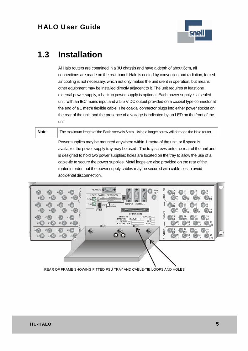
Power supplies may be mounted anywhere within 1 metre of the unit, or if space is
available, the power supply tray may be used . The tray screws onto the rear of the unit and
is designed to hold two power supplies; holes are located on the tray to allow the use of a
cable-tie to secure the power supplies. Metal loops are also provided on the rear of the
router in order that the power supply cables may be secured with cable-ties to avoid
accidental disconnection.
ALARMS
LEVEL SWITCH SETTINGS
1-16
17-32
0-78-F
SAME
DIFFERENT
SINGLE O/P 32X32
2 LEVELS OF 16X16
DUAL O/P 32X16
E’NET CTRL2(RS485)
E’NET
CONFIG 2 CTRL 1
ALG.REF
EXPANSION HALO 32 SDV/ASIMASTER SLAVE HD SERIAL No AESBATCH CODE A-VID
PSU A+5.5 ----- 6A PSU B
+5.5 ----- 6A
1 2 3 4
8765
1 2 3 4
8765
9 10 11 12
16151413
9 10 11 12
16151413
17[1]
18[2]
19[3]
20[4]
OU
TP
UT
SO
UT
PU
TS
INP
UT
S
OU
TP
UT
SO
UT
PU
TS
INP
UT
S
17[1]
18[2]
19[3]
20[4]
25[9]
26[10]
27[11]
28[12]
29[13]
30[14]
31[15]
32[16]
21[5]
22[6]
23[7]
24[8]
21[5]
22[6]
23[7]
24[8]
25[9]
26[10]
27[11]
28[12]
29[13]
30[14]
31[15]
32[16]
REAR OF FRAME SHOWING FITTED PSU TRAY AND CABLE-TIE LOOPS AND HOLES
6 Issue 8
HALO User Guide
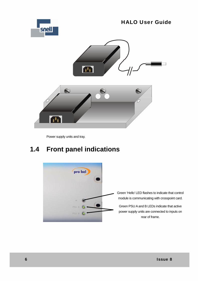
Power supply units and tray.
1.4 Front panel indications
Green ‘Hello’ LED flashes to indicate that control
module is communicating with crosspoint card.
Green PSU A and B LEDs indicate that active
power supply units are connected to inputs on
rear of frame.
HU-HALO 7
HALO User Guide
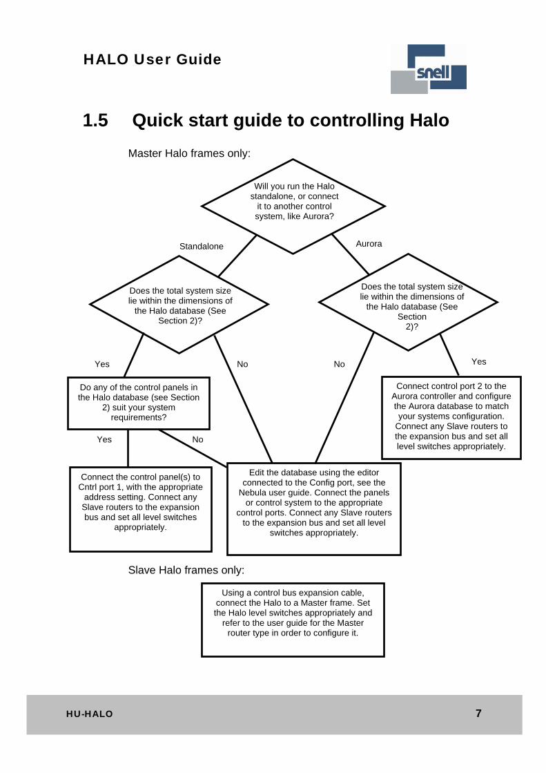
1.5 Quick start guide to controlling Halo
Master Halo frames only:
Slave Halo frames only:
Will you run the Halo standalone, or connect
it to another control system, like Aurora?
Does the total system size lie within the dimensions of
the Halo database (See Section 2)?
Edit the database using the editor connected to the Config port, see the
Nebula user guide. Connect the panels or control system to the appropriate
control ports. Connect any Slave routers to the expansion bus and set all level
switches appropriately.
Connect control port 2 to the Aurora controller and configure the Aurora database to match your systems configuration.
Connect any Slave routers to the expansion bus and set all level switches appropriately.
Standalone Aurora
Do any of the control panels in the Halo database (see Section
2) suit your system requirements?
Yes Yes No No
Using a control bus expansion cable, connect the Halo to a Master frame. Set the Halo level switches appropriately and
refer to the user guide for the Master router type in order to configure it.
No Yes
Connect the control panel(s) to Cntrl port 1, with the appropriate
address setting. Connect any Slave routers to the expansion bus and set all level switches
appropriately.
Does the total system size lie within the dimensions of
the Halo database (See Section
2)?
8 Issue 8
HALO User Guide
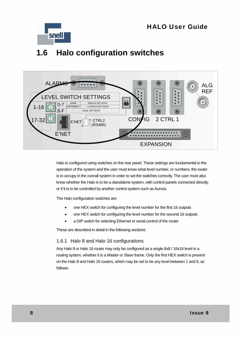
1.6 Halo configuration switches
Halo is configured using switches on the rear panel. These settings are fundamental to the
operation of the system and the user must know what level number, or numbers, the router
is to occupy in the overall system in order to set the switches correctly. The user must also
know whether the Halo is to be a standalone system, with control panels connected directly,
or if it is to be controlled by another control system such as Aurora.
The Halo configuration switches are:
one HEX switch for configuring the level number for the first 16 outputs
one HEX switch for configuring the level number for the second 16 outputs
a DIP switch for selecting Ethernet or serial control of the router
These are described in detail in the following sections:
1.6.1 Halo 8 and Halo 16 configurations
Any Halo 8 or Halo 16 router may only be configured as a single 8x8 / 16x16 level in a
routing system, whether it is a Master or Slave frame. Only the first HEX switch is present
on the Halo 8 and Halo 16 routers, which may be set to be any level between 1 and 8, as
follows:
ALARMS
LEVEL SWITCH SETTINGS
1-16
17-32
0-78-F
SAME
DIFFERENT
SINGLE O/P 32X32
2 LEVELS OF 16X16
DUAL O/P 32X16
E’NET CTRL2(RS485)
E’NET
CONFIG 2 CTRL 1
ALG.REF
EXPANSION
HU-HALO 9
HALO User Guide
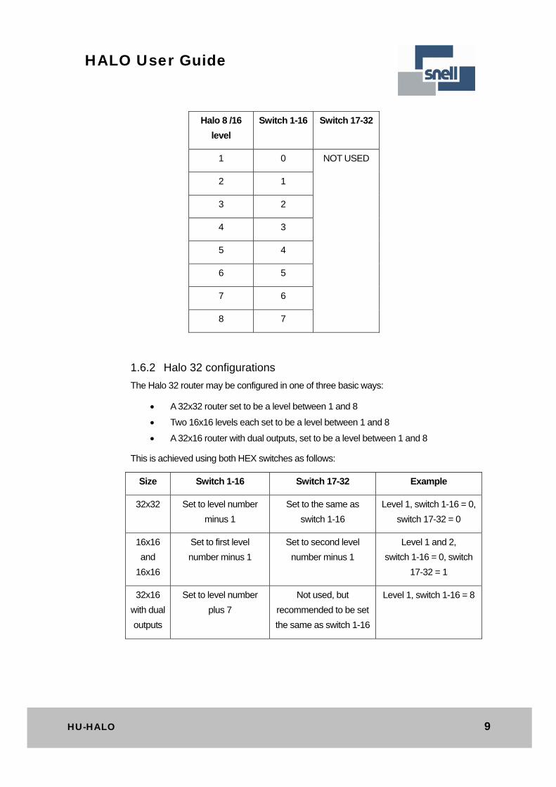
Halo 8 /16
level
Switch 1-16 Switch 17-32
1 0 NOT USED
2 1
3 2
4 3
5 4
6 5
7 6
8 7
1.6.2 Halo 32 configurations
The Halo 32 router may be configured in one of three basic ways:
A 32x32 router set to be a level between 1 and 8
Two 16x16 levels each set to be a level between 1 and 8
A 32x16 router with dual outputs, set to be a level between 1 and 8
This is achieved using both HEX switches as follows:
Size Switch 1-16 Switch 17-32 Example
32x32 Set to level number
minus 1
Set to the same as
switch 1-16
Level 1, switch 1-16 = 0,
switch 17-32 = 0
16x16
and
16x16
Set to first level
number minus 1
Set to second level
number minus 1
Level 1 and 2,
switch 1-16 = 0, switch
17-32 = 1
32x16
with dual
outputs
Set to level number
plus 7
Not used, but
recommended to be set
the same as switch 1-16
Level 1, switch 1-16 = 8
10 Issue 8
HALO User Guide
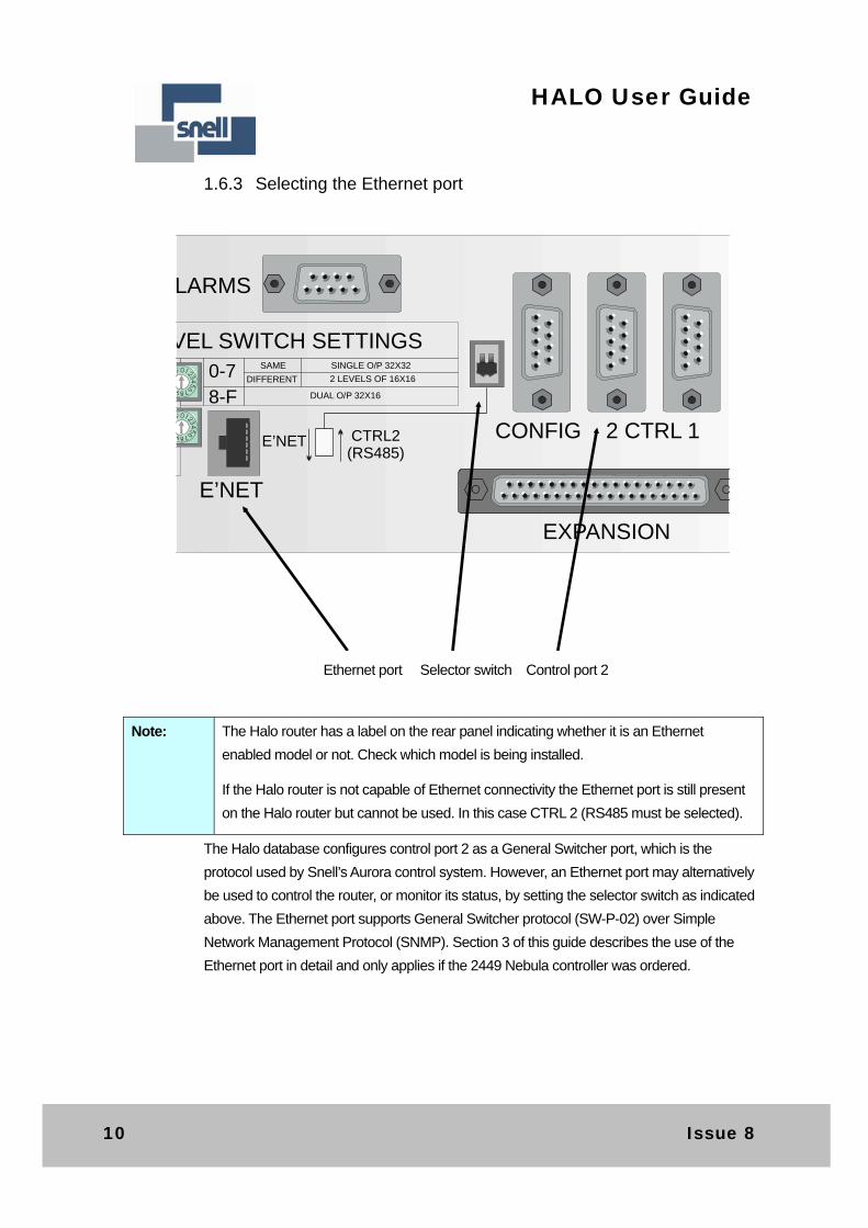
1.6.3 Selecting the Ethernet port
Note: The Halo router has a label on the rear panel indicating whether it is an Ethernet
enabled model or not. Check which model is being installed.
If the Halo router is not capable of Ethernet connectivity the Ethernet port is still present
on the Halo router but cannot be used. In this case CTRL 2 (RS485 must be selected).
The Halo database configures control port 2 as a General Switcher port, which is the
protocol used by Snell’s Aurora control system. However, an Ethernet port may alternatively
be used to control the router, or monitor its status, by setting the selector switch as indicated
above. The Ethernet port supports General Switcher protocol (SW-P-02) over Simple
Network Management Protocol (SNMP). Section 3 of this guide describes the use of the
Ethernet port in detail and only applies if the 2449 Nebula controller was ordered.
LARMS
VEL SWITCH SETTINGS0-78-F
SAME
DIFFERENT
SINGLE O/P 32X32
2 LEVELS OF 16X16
DUAL O/P 32X16
E’NET CTRL2(RS485)
E’NET
CONFIG 2 CTRL 1
EXPANSION
Ethernet port Selector switch Control port 2

HU-HALO 11
HALO User Guide
1.7 Signal connections
All video signals are connected to the rear panel, as follows:
ALARMS
LEVEL SWITCH SETTINGS
1-16
17-32
0-78-F
SAME
DIFFERENT
SINGLE O/P 32X32
2 LEVELS OF 16X16
DUAL O/P 32X16
E’NET CTRL2(RS485)
E’NET
CONFIG 2 CTRL 1
ALG.REF
EXPANSION
HALO 32 SDV/ASIMASTER SLAVE HD SERIAL No AESBATCH CODE A-VID
PSU A+5.5 ----- 6A
PSU B+5.5 ----- 6A
1 2 3 4
8765
1 2 3 4
8765
9 10 11 12
16151413
9 10 11 12
16151413
17[1]
18[2]
19[3]
20[4]
OU
TP
UT
SO
UT
PU
TS
INP
UT
S
OU
TP
UT
SO
UT
PU
TS
INP
UT
S
17[1]
18[2]
19[3]
20[4]
25[9]
26[10]
27[11]
28[12]
29[13]
30[14]
31[15]
32[16]
21[5]
22[6]
23[7]
24[8]
21[5]
22[6]
23[7]
24[8]
25[9]
26[10]
27[11]
28[12]
29[13]
30[14]
31[15]
32[16]
Halo32 and Halo 16 configurations have the first 16 inputs and outputs on the left side of the panel, as follows:
Halo 8 has only inputs and outputs 1-8
The Halo 32 uses signal connections on the right side of the panel, and the connector numbering reflects the three possible configurations, as follows:
32x32 uses standard numbering
two levels of 16x16, second level numbering in [brackets]
1 2 3 4
8765
1 2 3 4
8765
9 10 11 12
16151413
9 10 11 12
16151413
OU
TP
UT
SO
UT
PU
TS
INP
UT
S
12 Issue 8
HALO User Guide
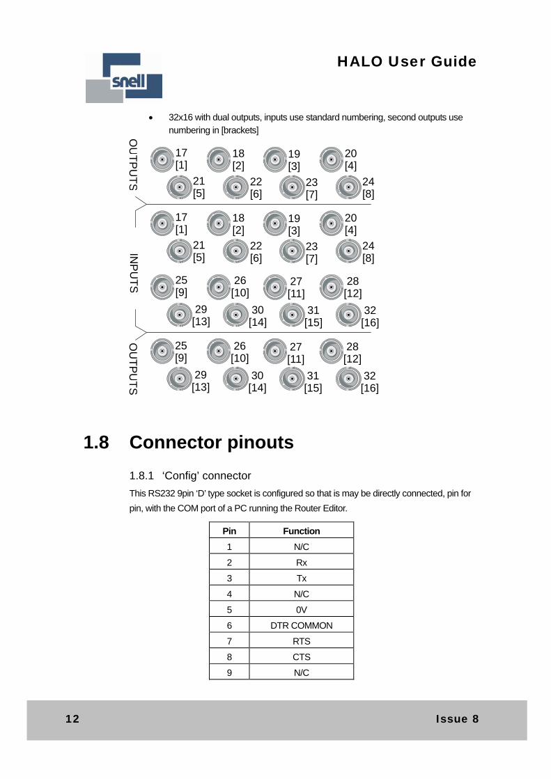
32x16 with dual outputs, inputs use standard numbering, second outputs use
numbering in [brackets]
17[1]
18[2]
19[3]
20[4]
OU
TP
UT
SO
UT
PU
TS
INP
UT
S
17[1]
18[2]
19[3]
20[4]
25[9]
26[10]
27[11]
28[12]
29[13]
30[14]
31[15]
32[16]
21[5]
22[6]
23[7]
24[8]
21[5]
22[6]
23[7]
24[8]
25[9]
26[10]
27[11]
28[12]
29[13]
30[14]
31[15]
32[16]
1.8 Connector pinouts
1.8.1 ‘Config’ connector
This RS232 9pin ‘D’ type socket is configured so that is may be directly connected, pin for
pin, with the COM port of a PC running the Router Editor.
Pin Function
1 N/C
2 Rx
3 Tx
4 N/C
5 0V
6 DTR COMMON
7 RTS
8 CTS
9 N/C
HU-HALO 13
HALO User Guide
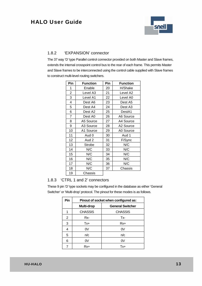
1.8.2 ‘EXPANSION’ connector
The 37 way ‘D’ type Parallel control connector provided on both Master and Slave frames,
extends the internal crosspoint control bus to the rear of each frame. This permits Master
and Slave frames to be interconnected using the control cable supplied with Slave frames
to construct multi-level routing switchers.
Pin Function Pin Function 1 Enable 20 H/Shake 2 Level A3 21 Level A2 3 Level A1 22 Level A0 4 Dest A6 23 Dest A5 5 Dest A4 24 Dest A3 6 Dest A2 25 DestA1 7 Dest A0 26 A6 Source 8 A5 Source 27 A4 Source 9 A3 Source 28 A2 Source 10 A1 Source 29 A0 Source 11 Aud 0 30 Aud 1 12 Aud 2 31 F/Sync 13 Strobe 32 N/C 14 N/C 33 N/C 15 N/C 34 N/C 16 N/C 35 N/C 17 N/C 36 N/C 18 N/C 37 Chassis 19 Chassis
1.8.3 ‘CTRL 1 and 2’ connectors
These 9 pin ‘D’ type sockets may be configured in the database as either ‘General
Switcher’ or ‘Multi-drop’ protocol. The pinout for these modes is as follows.
Pin Pinout of socket when configured as:
Multi-drop General Switcher
1 CHASSIS CHASSIS
2 Rx- Tx-
3 Tx+ Rx+
4 0V 0V
5 n/c n/c
6 0V 0V
7 Rx+ Tx+
14 Issue 8
HALO User Guide
8 Tx- Rx-
9 CHASSIS CHASSIS
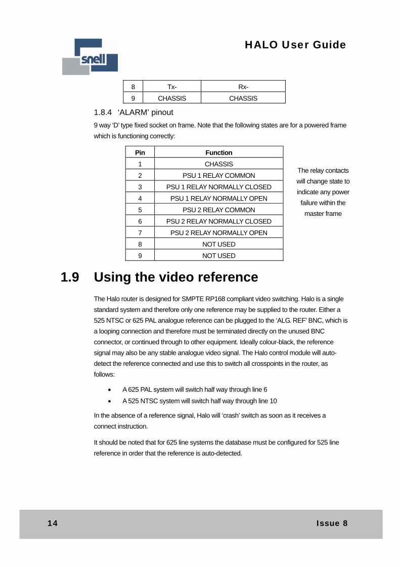
1.8.4 ‘ALARM’ pinout
9 way ‘D’ type fixed socket on frame. Note that the following states are for a powered frame
which is functioning correctly:
Pin Function
1 CHASSIS
2 PSU 1 RELAY COMMON
3 PSU 1 RELAY NORMALLY CLOSED
4 PSU 1 RELAY NORMALLY OPEN
5 PSU 2 RELAY COMMON
6 PSU 2 RELAY NORMALLY CLOSED
7 PSU 2 RELAY NORMALLY OPEN
8 NOT USED
9 NOT USED
1.9 Using the video reference
The Halo router is designed for SMPTE RP168 compliant video switching. Halo is a single
standard system and therefore only one reference may be supplied to the router. Either a
525 NTSC or 625 PAL analogue reference can be plugged to the ‘ALG. REF’ BNC, which is
a looping connection and therefore must be terminated directly on the unused BNC
connector, or continued through to other equipment. Ideally colour-black, the reference
signal may also be any stable analogue video signal. The Halo control module will auto-
detect the reference connected and use this to switch all crosspoints in the router, as
follows:
A 625 PAL system will switch half way through line 6
A 525 NTSC system will switch half way through line 10
In the absence of a reference signal, Halo will ‘crash’ switch as soon as it receives a
connect instruction.
It should be noted that for 625 line systems the database must be configured for 525 line
reference in order that the reference is auto-detected.
The relay contacts
will change state to
indicate any power
failure within the
master frame
HU-HALO 15
HALO User Guide
As Halo has a single 525/625 reference, to allow SMPTE RP168 compliant switching of HD
signals, the SD reference applied to the Halo must be offset relative to the HD signals
entering the Halo, to produce a switching pulse at the correct point.
The offsets required on an SD reference to switch at the correct point in a HD signal are
listed below:
50Hz Systems (using 625/50 reference): 1080i/50 119us/1 line 55us early 720p/50 177us/2 lines 49us early 59.94Hz systems (using 525/59.94 reference): 1080i/59.94 218us/3 lines 27us early 720p/59.94 267us/4 lines 12us early
Note: these figures are approximate as there are timing tolerance windows on all
standards, and some variation on the Halo itself. Therefore, minor adjustments may be
required around these values, specific to each system.

16 Issue 8
HALO User Guide
2 The Halo database
Every Master Halo is supplied with a pre-configured database, which is held in non-volatile
memory on the control module, inside the unit. Halo uses the Nebula control system, just
like the Freeway, Axis and Sirius router products, and in common with these systems, this
database may be edited to suit the users exact requirements. However, unlike these
systems, the user does not have to choose between a ‘fixed’ and ‘editable’ database,
because in Halo only one database is accessible, which is pre-configured, but may also be
directly edited. The used must refer to the Nebula user guide for instructions on editing the
database.
2.1 Database configuration
The pre-configured Halo database has the following parameters:
Parameter Setting
Level Types 4 levels of 32x32 each
level 1 and 2 Sirius/Freeway 128 Normal SDV
level 3 and 4 Sirius/Freeway 128 Normal Audio mix
8 Character Source Names ‘SRC 1’ - ‘SRC 32’
8 Character Dest Asc. Names ‘DEST 1’ - ‘DEST 32’
Route Inhibits None
Salvos None
Source Associations 1 to 32 are 1 to 1, 33 to 192 not configured
Destination Associations 1 to 32 are 1 to 1, 33 to 192 not configured
Trigger Method per source Set to 525 in order to auto-detect video reference
Source Audio Parameters All set for normal stereo
Destination Audio parameters All set to normal stereo
Control port 1 is configured as a multi-drop port with control panels configured as follows:

HU-HALO 17
HALO User Guide
Control Port 1 – Multi-drop
Panel
address
Panel
Name
Panel
type
Destinations Sources Overrides Levels/
Brightness
1 PNL 1-1 6276-XY All All None All/6
2 PNL 1-2 6276-XY All All None All/6
3 PNL 1-3 6276-XY ALL All None All/6
4 PNL 1-4 6277-8 1-8 All None All/6
5 PNL 1-5 6277-8 9-16 All None All/6
6 PNL 1-6 6277-8 17-24 All None All/6
7 PNL 1-7 6277-8 25-32 All None All/6
8 PNL 1-8 6705 1 1-32 1 to 8 All
9 PNL 1-9 6705 2 1-32 1 to 8 All
10 PNL 1-10 6705 3 1-32 1 to 8 All
11 PNL 1-11 6705 4 1-32 1 to 8 All
12 PNL 1-12 6705 5 1-32 1 to 8 All
13 PNL 1-13 6705 6 1-32 1 to 8 All
14 PNL 1-14 6705 7 1-32 1 to 8 All
15 PNL 1-15 6705 8 1-32 1 to 8 All
16 PNL 1-16 6705 1-16 1-16 None All
18 Issue 8
HALO User Guide
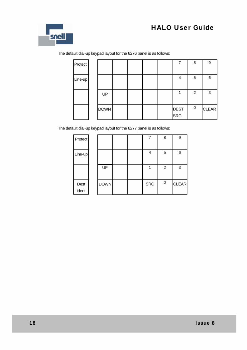
The default dial-up keypad layout for the 6276 panel is as follows:
The default dial-up keypad layout for the 6277 panel is as follows:
Protect
Line-up
7 8 9
4 5 6
UP 1 2 3
DOWN DEST
SRC
0 CLEAR
Protect
Line-up
Dest
ident
7 8 9
4 5 6
UP
1 2 3
DOWN SRC 0 CLEAR
HU-HALO 19
HALO User Guide
3 Using the Ethernet port
Important
Note:
This section only is only applicable if the Halo router is an Ethernet enabled model. See
the label on the rear panel of the Halo router for details.
If the Halo router is not Ethernet enabled then the Ethernet port is still present on the
rear panel but cannot be used and so this section does not apply.
3.1 Introduction
The Halo rear panel has one RJ45 type Ethernet connectors fitted. The following must be
configured to activate the Ethernet port:
The rear panel selector switch must be set to ‘E’NET’
RS485 port 2 protocol must be set to General Switcher protocol in database
The port is configured for connecting to a 10 Base T Ethernet Hub, and when configured
correctly, will allow the router to be controlled, and for status information to be requested,
using Snell’s General Switcher protocol over SNMP.
Ethernet support for Halo is provided using a ‘SC12’ chip, which is a 80186 processor
system complete with RAM, NVRAM, serial and Ethernet ports all in one package. The chip
has system software and configuration files which may all be loaded and edited using a
software tool supplied with the system. This tool may also be used to test the Ethernet
connection, control the router and view the status.
This chapter describes the software configuration of the SC12 chip using the supplied
configuration tool.
3.2 Connecting Halo to a network
A standard CAT5 patch cord may be used to connect the Halo active Ethernet port to a 10
Base T hub or switch. By default, the SC12 chip is configured for DHCP, meaning that a
DHCP Server must be present on the same network segment in order an IP address to be
assigned. Without this, the Snell configuration tool must be used to manually assign an
address. The SC12 chip includes TELNET and FTP servers in order to support the
configuration tool.
20 Issue 8
HALO User Guide
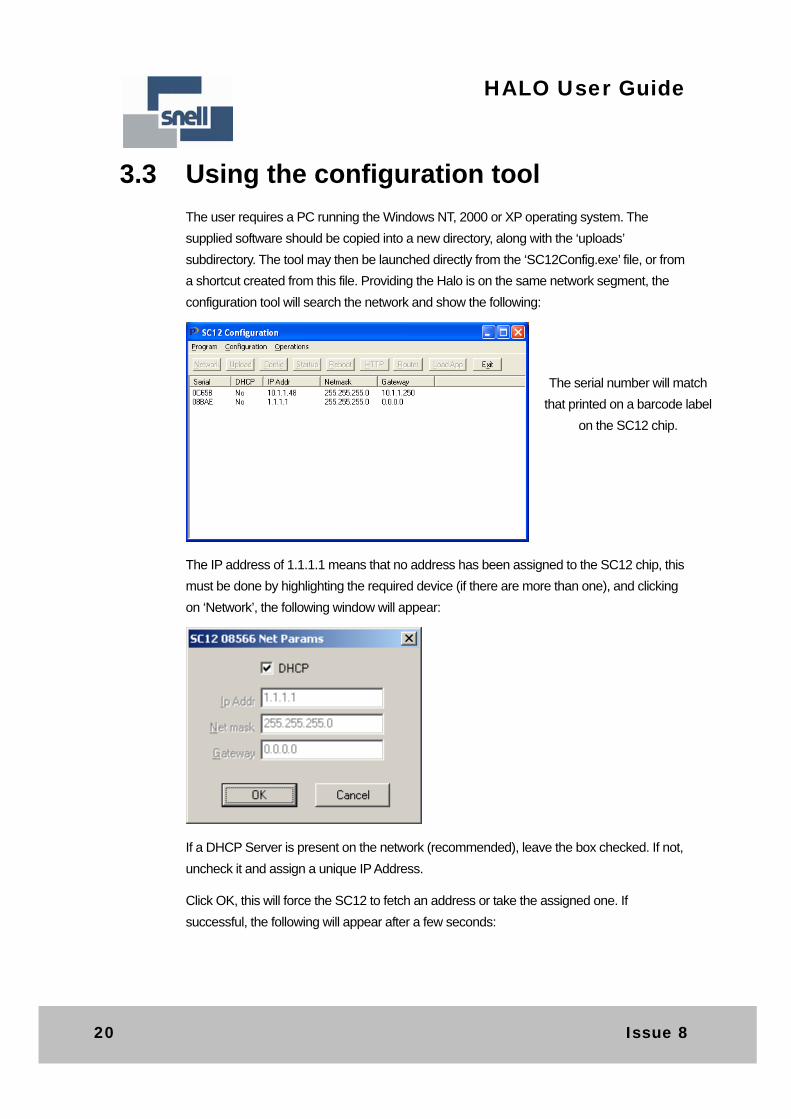
3.3 Using the configuration tool
The user requires a PC running the Windows NT, 2000 or XP operating system. The
supplied software should be copied into a new directory, along with the ‘uploads’
subdirectory. The tool may then be launched directly from the ‘SC12Config.exe’ file, or from
a shortcut created from this file. Providing the Halo is on the same network segment, the
configuration tool will search the network and show the following:
The IP address of 1.1.1.1 means that no address has been assigned to the SC12 chip, this
must be done by highlighting the required device (if there are more than one), and clicking
on ‘Network’, the following window will appear:
If a DHCP Server is present on the network (recommended), leave the box checked. If not,
uncheck it and assign a unique IP Address.
Click OK, this will force the SC12 to fetch an address or take the assigned one. If
successful, the following will appear after a few seconds:
The serial number will match
that printed on a barcode label
on the SC12 chip.
HU-HALO 21
HALO User Guide
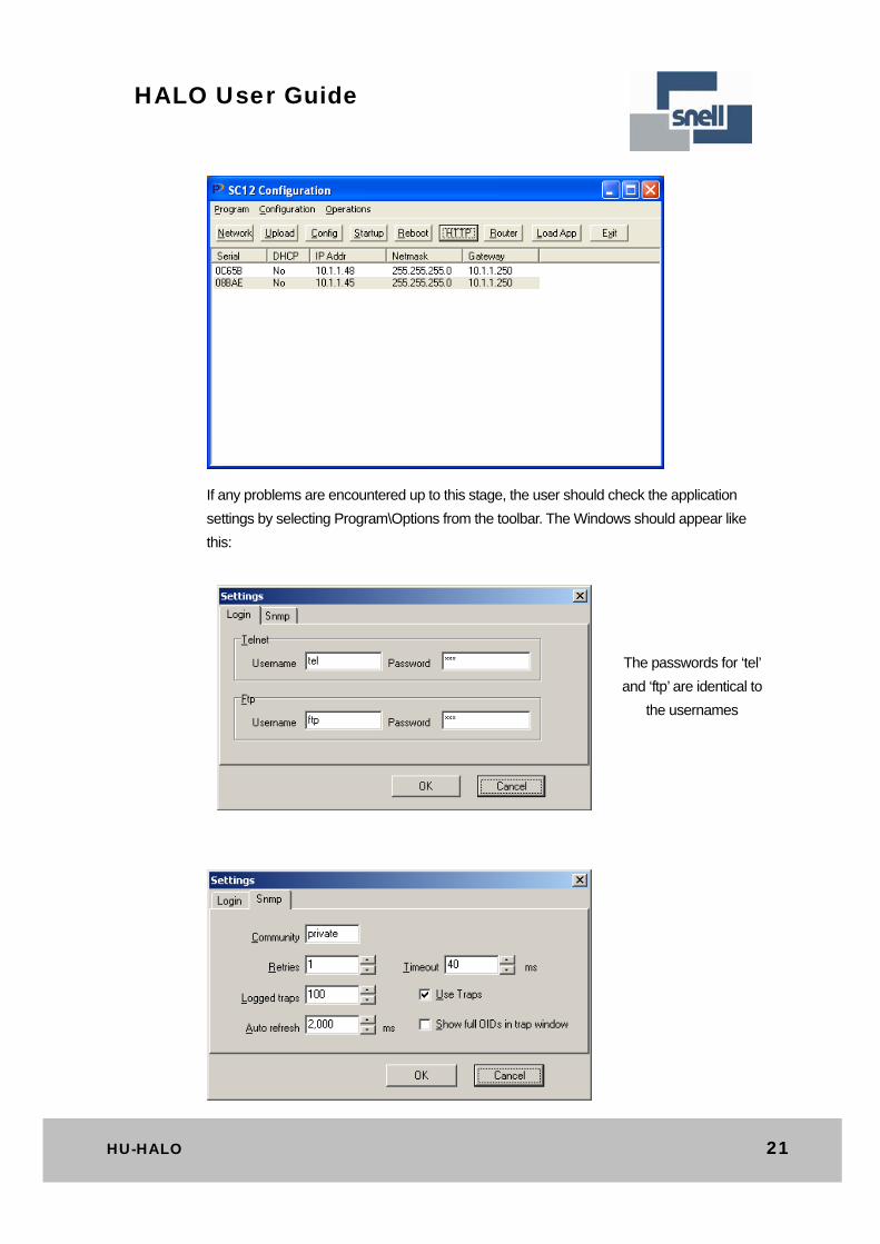
If any problems are encountered up to this stage, the user should check the application
settings by selecting Program\Options from the toolbar. The Windows should appear like
this:
The passwords for ‘tel’
and ‘ftp’ are identical to
the usernames
22 Issue 8
HALO User Guide
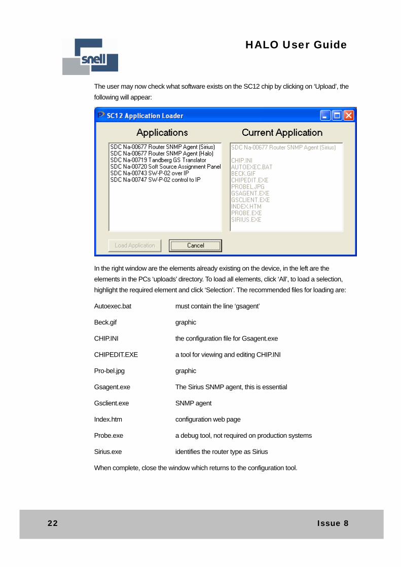
The user may now check what software exists on the SC12 chip by clicking on ‘Upload’, the
following will appear:
In the right window are the elements already existing on the device, in the left are the
elements in the PCs ‘uploads’ directory. To load all elements, click ‘All’, to load a selection,
highlight the required element and click ‘Selection’. The recommended files for loading are:
Autoexec.bat must contain the line ‘gsagent’
Beck.gif graphic
CHIP.INI the configuration file for Gsagent.exe
CHIPEDIT.EXE a tool for viewing and editing CHIP.INI
Pro-bel.jpg graphic
Gsagent.exe The Sirius SNMP agent, this is essential
Gsclient.exe SNMP agent
Index.htm configuration web page
Probe.exe a debug tool, not required on production systems
Sirius.exe identifies the router type as Sirius
When complete, close the window which returns to the configuration tool.
HU-HALO 23
HALO User Guide
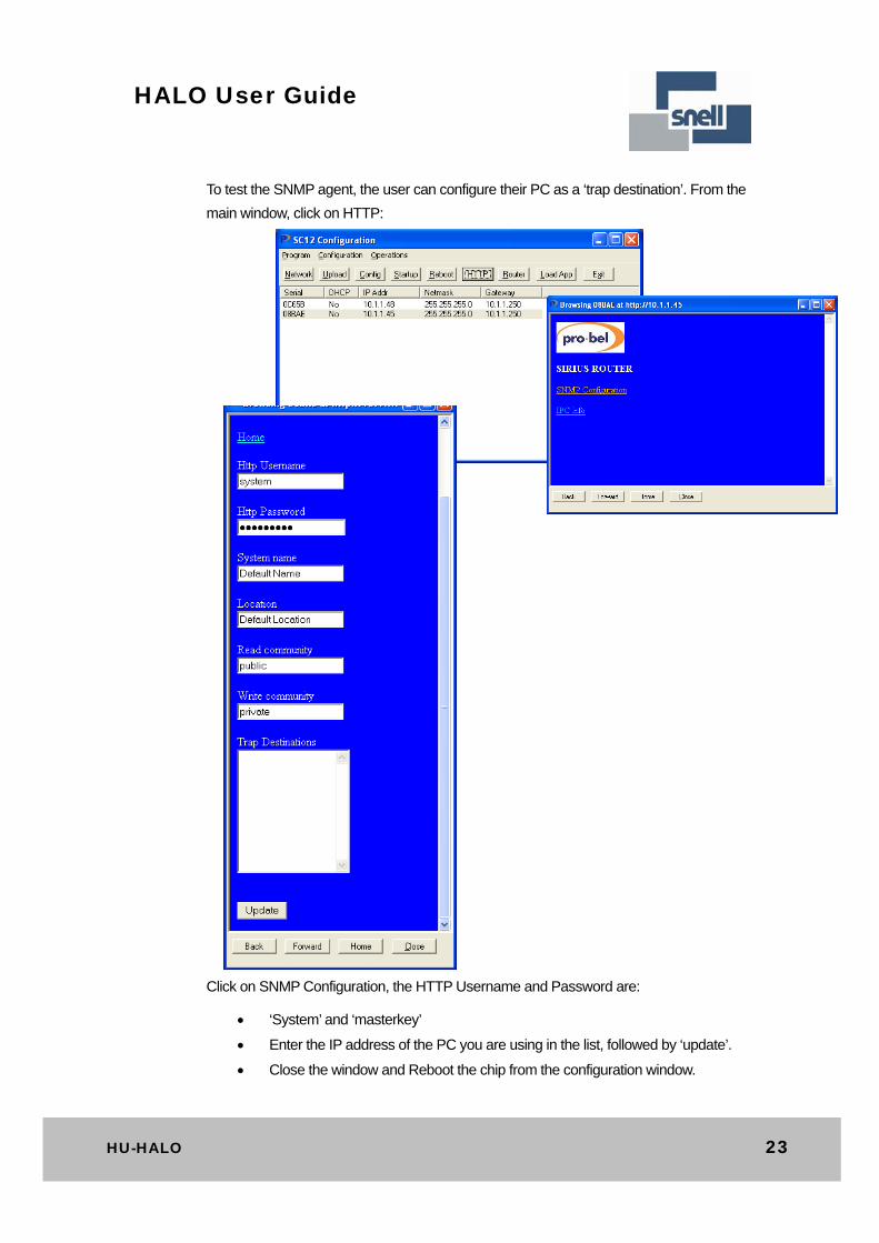
To test the SNMP agent, the user can configure their PC as a ‘trap destination’. From the
main window, click on HTTP:
Click on SNMP Configuration, the HTTP Username and Password are:
‘System’ and ‘masterkey’
Enter the IP address of the PC you are using in the list, followed by ‘update’.
Close the window and Reboot the chip from the configuration window.
24 Issue 8
HALO User Guide
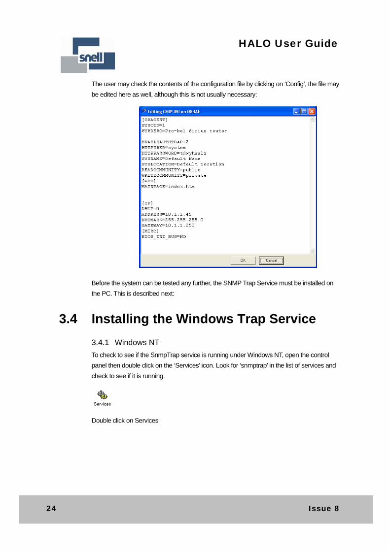
The user may check the contents of the configuration file by clicking on ‘Config’, the file may
be edited here as well, although this is not usually necessary:
Before the system can be tested any further, the SNMP Trap Service must be installed on
the PC. This is described next:
3.4 Installing the Windows Trap Service
3.4.1 Windows NT
To check to see if the SnmpTrap service is running under Windows NT, open the control
panel then double click on the ‘Services’ icon. Look for ‘snmptrap’ in the list of services and
check to see if it is running.
Double click on Services
HU-HALO 25
HALO User Guide
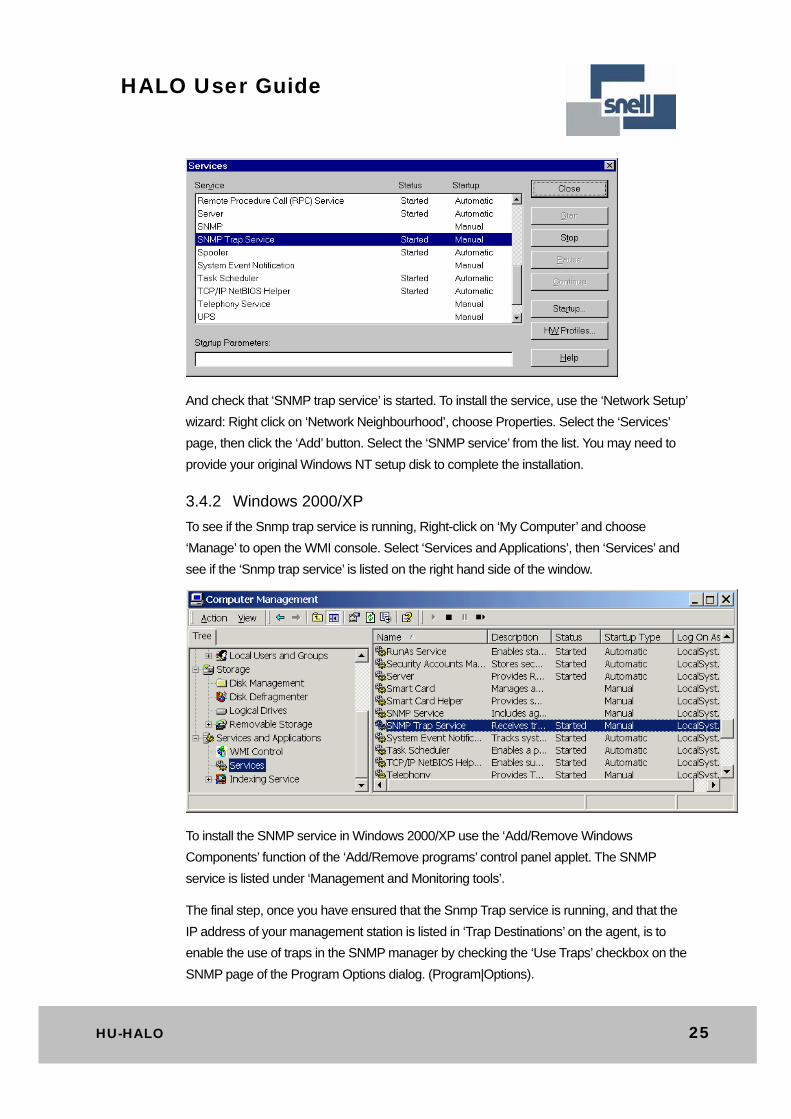
And check that ‘SNMP trap service’ is started. To install the service, use the ‘Network Setup’
wizard: Right click on ‘Network Neighbourhood’, choose Properties. Select the ‘Services’
page, then click the ‘Add’ button. Select the ‘SNMP service’ from the list. You may need to
provide your original Windows NT setup disk to complete the installation.
3.4.2 Windows 2000/XP
To see if the Snmp trap service is running, Right-click on ‘My Computer’ and choose
‘Manage’ to open the WMI console. Select ‘Services and Applications’, then ‘Services’ and
see if the ‘Snmp trap service’ is listed on the right hand side of the window.
To install the SNMP service in Windows 2000/XP use the ‘Add/Remove Windows
Components’ function of the ‘Add/Remove programs’ control panel applet. The SNMP
service is listed under ‘Management and Monitoring tools’.
The final step, once you have ensured that the Snmp Trap service is running, and that the
IP address of your management station is listed in ‘Trap Destinations’ on the agent, is to
enable the use of traps in the SNMP manager by checking the ‘Use Traps’ checkbox on the
SNMP page of the Program Options dialog. (Program|Options).
26 Issue 8
HALO User Guide
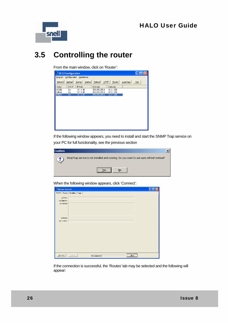
3.5 Controlling the router
From the main window, click on ‘Router’:
If the following window appears, you need to install and start the SNMP Trap service on
your PC for full functionality, see the previous section
When the following window appears, click ‘Connect’:
If the connection is successful, the ‘Routes’ tab may be selected and the following will appear:
HU-HALO 27
HALO User Guide
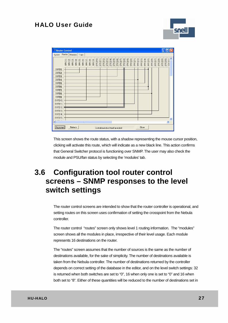
This screen shows the route status, with a shadow representing the mouse cursor position,
clicking will activate this route, which will indicate as a new black line. This action confirms
that General Switcher protocol is functioning over SNMP. The user may also check the
module and PSU/fan status by selecting the ‘modules’ tab.
3.6 Configuration tool router control screens – SNMP responses to the level switch settings
The router control screens are intended to show that the router controller is operational, and
setting routes on this screen uses confirmation of setting the crosspoint from the Nebula
controller.
The router control “routes” screen only shows level 1 routing information. The “modules”
screen shows all the modules in place, irrespective of their level usage. Each module
represents 16 destinations on the router.
The “routes” screen assumes that the number of sources is the same as the number of
destinations available, for the sake of simplicity. The number of destinations available is
taken from the Nebula controller. The number of destinations returned by the controller
depends on correct setting of the database in the editor, and on the level switch settings: 32
is returned when both switches are set to “0”, 16 when only one is set to “0” and 16 when
both set to “8”. Either of these quantities will be reduced to the number of destinations set in
28 Issue 8
HALO User Guide
the database, if that figure is lower. Other switch settings realise zero destinations as none
exist at level 1.
Although the square router assumption is made by the configuration tool’s display, the
Nebula controller will have also informed the Ethernet controller of the number of sources
as set by the configured database. This limit determines the SNMP response to a particular
destination-source routing request:
16x16 router: The user should reduce the number of sources from 32 to 16, in
the Nebula editor, otherwise source values 17-32 will be affirmed by the SNMP
trap incorrectly.
32x16 router: The user should set the number of sources to 32 in the Nebula
editor. The source values 17-32 cannot be entered from the configuration tool,
but they can be set from other SNMP interface tools, and an affirmative SNMP
trap will be sent.
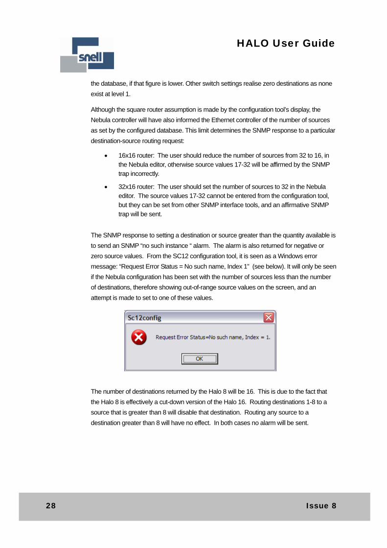
The SNMP response to setting a destination or source greater than the quantity available is
to send an SNMP “no such instance “ alarm. The alarm is also returned for negative or
zero source values. From the SC12 configuration tool, it is seen as a Windows error
message: “Request Error Status = No such name, Index 1” (see below). It will only be seen
if the Nebula configuration has been set with the number of sources less than the number
of destinations, therefore showing out-of-range source values on the screen, and an
attempt is made to set to one of these values.
The number of destinations returned by the Halo 8 will be 16. This is due to the fact that
the Halo 8 is effectively a cut-down version of the Halo 16. Routing destinations 1-8 to a
source that is greater than 8 will disable that destination. Routing any source to a
destination greater than 8 will have no effect. In both cases no alarm will be sent.
HU-HALO 29
HALO User Guide
3.7 SNMP terminology
SNMP is a complex subject and cannot be fully described within this manual. The following
is a summary of terms that may be encountered:
Manager and Agent
The terms ‘client’ and ‘server’ tend not to be used when discussing SNMP. Instead, the
terms ‘Manager’ and ‘Agent’ are used. The agent is the device being managed, normally
some sort of network infrastructure such as a router or hub. The manager is the software
that is using SNMP to communicate with agents. The reason that the terms ‘client’ and
‘server’ are not appropriate is that these terms imply a central server supplying services to a
number of clients. With SNMP normally one manager is used to manage a number of
agents, although it is perfectly possible for an agent to be connected to more than one
manager at once.
MIB
SNMP is a ‘variable-based’ protocol. An agent provides an interface comprising a number
of variables, these can be scalar variables (a single value, for example ‘SysLocation’ a
string describing the physical location of the device) or tables, which are lists of structured
records, like database tables. Each device will want to provide data that is structured in
accordance with the type of the device. The structure of the information provided via SNMP
for a particular device is called a “management information base2” or MIB. In the case of
SNMP the MIB is stored in a file – wherein the structure is of the information is described
using a language called ASN.1.
MIB2
Although a specific type of device will have a MIB that is particular to its function there are
some variables that are deemed to be common to all devices managed by SNMP. These
variables are stored in the ‘MIB2’ branch of the overall MIB tree. All SNMP managed
devices are supposed to support these variables.
OID
Variables within a MIB are identified with an OID, or ‘OBJECT_IDENTIFER’. This is a long
sequence of numbers, separated by dots. These numbers are globally unique and are
managed by the IANA on behalf of the IETF. In practice the IANA does not approve every
OID, but assigns an OID to an organisation, which then becomes a ‘branch’ of the global
namespace. Pro-bel’s OID is 1.3.6.1.4.1.6419.1 . The OID for the Halo router is
1.3.6.1.4.1.6419.1.1.2.
30 Issue 8
HALO User Guide
PDU
PDU stands for ‘Protocol Data Unit’ and is a UDP packet conforming to SNMP format
specifications sent between manager and agent. There are three four basic PDU types:
GET, GETNEXT, SET and TRAP. For example, to retrieve a variable from an agent, a
manager sends a GET PDU then waits for a GET response from the agent. Similarly with
GETNEXT (which retrieves the ‘next’ variable in the MIB from the one asked for) and SET.
TRAP
A manager initiates GET, GETNEXT and SET transactions, by sending an appropriate
PDU. A TRAP, on the other hand, is send unsolicited by the Agent. The manager does not
have to respond to a TRAP. TRAPs are intended to allow an agent to inform a manager
that something requires attention. It is then up to the manager to decide what action to take.
A TRAP can include variable bindings, but it doesn’t normally include a lot of data –
normally it is sufficient to indicate to the manager what has changed, so the manager can
then use a GET to retrieve the information.
HU-HALO 31
HALO User Guide
4 Trouble shooting
The following information is intended as a brief guide for diagnosing faults associated with a
Halo router.
It should be noted that Halo frames are sealed units and contain no user serviceable parts,
therefore should this product require servicing, you should refer to Snell or your local
distributor.
All the following assume that at least one power supply is powered and functioning in each
frame in the system.
Check the front panel LEDs: At least one power supply LED must be on
A Halo must have a flashing ‘hello’ LED to indicate communication with the
Master controller
The PC Editor will not connect ‘on-line’ Check that the cable is connected to the Halo ‘CONFIG’ port
Check that the router is a Master frame
Check the Editor is configured for the correct PC COM port
Check the baud rate setting in the editor for 38400
Check cable continuity
The Network connection doesn’t work Check the label on the rear panel to make sure the Halo router is an Ethernet
enabled model.
If a non Ethernet enabled Halo router was ordered/supplied Ethernet is not
supported.
The control panels connected to Halo do not function Check that the panels are connected to a Master frame
If using the pre-configured database, check the panels are connected to Control
port 1
If the database has been edited, check the database configuration with an editor
Check the HEX address of the control panels matches the database setting
Check the control panel DIP switch settings in the Nebula user guide
Check cable continuity

32 Issue 8
HALO User Guide
The external control system does not control Halo Check that the control system is connected to a Master router
Check the Halo level configuration HEX switches are correct
If using the pre-configured database, check that the external control system is
connected to Control port 2
If the database has been edited, check that the database configuration has a
General Switcher port configured with an editor
Check cable interconnections
Check electrical characteristics and protocol of controlling device are compatible
with that configured into the database
The panel is communicating but there are no (or incorrect) responses to button presses - panels not in self-test
Check cable interconnections
Check that the panel has been configured in the database as the correct type
Ensure that each panel on the multidrop chain has a unique serial address
Check that the panel configuration switches are set correctly, see the Nebula
user guide
Check all level switches on routers are set correctly
Video routes do not switch ‘cleanly’ The Halo router is designed for SMPTE RP168 compliant video switching
Check that a suitable video reference is plugged to the rear connection
Check that the analogue video reference is correctly terminated
Check settings in database for 525 reference, which configures auto-detect
The panel controls the wrong destination Check that the panel is assigned correctly in database
Check the panel is set to the correct address
The panel cannot select a crosspoint? If the database has been edited, check for:
panel assignment
level active
route not inhibited
no override active
level controllable
Check router level HEX switch setting
HU-HALO 33
HALO User Guide
The Master unit is switching but Slave levels are not following Ensure that the SLAVE bus cable is fitted correctly
Check that the Master and Slave routers have the appropriate level mappings set
Check the database is set up for a multi-level system
34 Issue 8
HALO User Guide
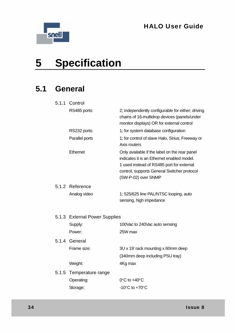
5 Specification
5.1 General
5.1.1 Control
RS485 ports: 2; independently configurable for either; driving
chains of 16-multidrop devices (panels/under
monitor displays) OR for external control
RS232 ports: 1; for system database configuration
Parallel ports 1; for control of slave Halo, Sirius, Freeway or
Axis routers
Ethernet Only available if the label on the rear panel
indicates it is an Ethernet enabled model.
1 used instead of RS485 port for external
control, supports General Switcher protocol
(SW-P-02) over SNMP
5.1.2 Reference
Analog video 1; 525/625 line PAL/NTSC looping, auto
sensing, high impedance
5.1.3 External Power Supplies
Supply: 100Vac to 240Vac auto sensing
Power: 25W max
5.1.4 General
Frame size: 3U x 19’ rack mounting x 60mm deep
(340mm deep including PSU tray)
Weight: 4Kg max
5.1.5 Temperature range
Operating: 0C to +40C
Storage: -10C to +70C
HU-HALO 35
HALO User Guide
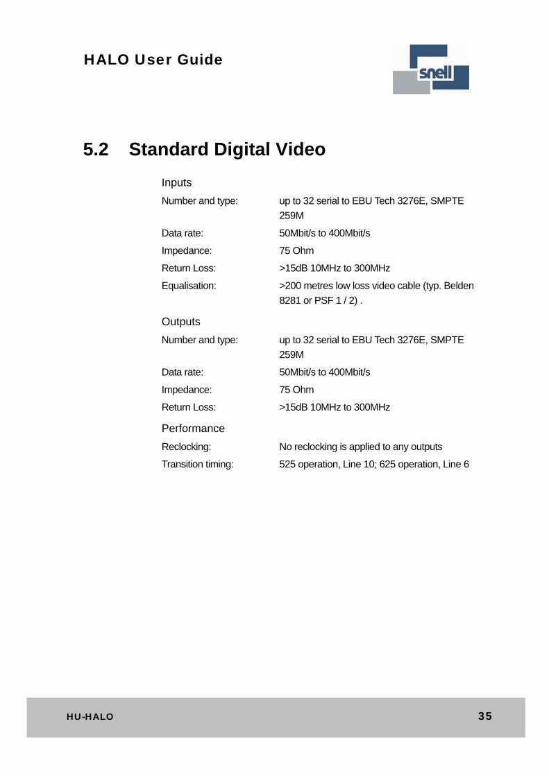
5.2 Standard Digital Video
Inputs
Number and type: up to 32 serial to EBU Tech 3276E, SMPTE
259M
Data rate: 50Mbit/s to 400Mbit/s
Impedance: 75 Ohm
Return Loss: >15dB 10MHz to 300MHz
Equalisation: >200 metres low loss video cable (typ. Belden
8281 or PSF 1 / 2) .
Outputs
Number and type: up to 32 serial to EBU Tech 3276E, SMPTE
259M
Data rate: 50Mbit/s to 400Mbit/s
Impedance: 75 Ohm
Return Loss: >15dB 10MHz to 300MHz
Performance
Reclocking: No reclocking is applied to any outputs
Transition timing: 525 operation, Line 10; 625 operation, Line 6

36 Issue 8
HALO User Guide
5.3 High Definition Television video
Inputs
Number and type: up to 32 to SMPTE 292M Unbalanced serial
digital interface for high definition television
systems
Impedance: 75 Ohm
Data rate: 10 Mbit/s to 1.485 Gbit/s
Return loss: >15dB 5MHz to 1.485GHz
Amplitude: 800mV p-p nominal
Equalisation: Up to 100m of Belden 1694A
Outputs
Number and type: up to 32 to SMPTE 292M Unbalanced serial
digital interface for high definition television
systems
Impedance: 75 Ohm
Data rate: 10 Mbit/s to 1.485 Gbit/s
Return loss: >15dB 5MHz to 1.485GHz
Amplitude: 800mV p-p +/-10%
Equalisation: Up to 100m of Belden 1694A


![[Superpartituras.com.Br] Halo (19)](https://img.pdfslide.net/doc/110x75/577c7c341a28abe05499b6c9/superpartiturascombr-halo-19.jpg)