Embed Size (px)
Citation preview
Ta b l e o f Co n t e n t s
HUB CITY MOTORIZED WORM GEAR REDUCERS
C-1CALL: (605) 225-0360 FAX: (605) 225-0567
Introductory Information . . . . . . . . . . . . . . . . . . . . . . . . . . . . . . . . . . . . . . .C-2 Thru C-3
Recess Action Worm Gearing . . . . . . . . . . . . . . . . . . . . . . . . . . . . . . . . . . . . . . . .C-4
Engineering Parameters . . . . . . . . . . . . . . . . . . . . . . . . . . . . . . . . . . . . . . . . . . .C-5
Rating Parameters . . . . . . . . . . . . . . . . . . . . . . . . . . . . . . . . . . . . . . . . . . . . . . . .C-6
Pre-Selection Information . . . . . . . . . . . . . . . . . . . . . . . . . . . . . . . . . . . . . . . . . .C-7
How To Select and Order Standard Models . . . . . . . . . . . . . . . . . . . . . . . . . . . . .C-8
Single Reduction Selection . . . . . . . . . . . . . . . . . . . . . . . . . . . . . . . . . . . . . .C-9 Thru C-13
Single Reduction Features . . . . . . . . . . . . . . . . . . . . . . . . . . . . . . . . . . . . . . . . . .C-14
Single Reduction General Specifications . . . . . . . . . . . . . . . . . . . . . . . . . . . . . . .C-15
Single Reduction Output Shaft Models . . . . . . . . . . . . . . . . . . . . . . . . . .C-16 Thru C-17
Single Reduction Hollow Bore Models . . . . . . . . . . . . . . . . . . . . . . . . . .C-18 Thru C-19
Single Reduction Bore Charts . . . . . . . . . . . . . . . . . . . . . . . . . . . . . . . . . . . . . . .C-20
Double Reduction Selection Worm\Worm . . . . . . . . . . . . . . . . . . . . . . . . . . .C-21 Thru C-27
Double Reduction Features Worm\Worm . . . . . . . . . . . . . . . . . . . . . . . . . . . . . . .C-28
Double Reduction General Specifications . . . . . . . . . . . . . . . . . . . . . . . . . . . . . .C-29
Double Reduction Output Shaft Models Worm\Worm . . . . . . . . . . . . . . . .C-30 Thru C-31
Double Reduction Hollow Bore Models Worm\Worm . . . . . . . . . . . . . . . .C-32 Thru C-33
Double Reduction Bore Charts . . . . . . . . . . . . . . . . . . . . . . . . . . . . . . . . . . . . . .C-34
Double Reduction Selection Helical\Worm . . . . . . . . . . . . . . . . . . . . . . . . . .C-36 Thru C-43
Double Reduction Features Helical\Worm . . . . . . . . . . . . . . . . . . . . . . . . . . . . . . .C-44
Double Reduction General Specifications Helical\Worm . . . . . . . . . . . . . . . . . . . .C-45
Double Reduction Output Shaft Models Helical\Worm . . . . . . . . . . . . . . . .C-46 Thru C-47
Double Reduction Hollow Bore Models Helical\Worm . . . . . . . . . . . . . . . .C-48 Thru C-49
Double Reduction Bore Charts . . . . . . . . . . . . . . . . . . . . . . . . . . . . . . . . . . . . . .C-50
Electric Motors . . . . . . . . . . . . . . . . . . . . . . . . . . . . . . . . . . . . . . . . . . . . . .C-51 Thru C-53
Fan Kits, Lubrication, Installation, Maintenance . . . . . . . . . . . . . . . . . . . .C-54 Thru C-59
Warning Information . . . . . . . . . . . . . . . . . . . . . . . . . . . . . . . . . . . . . . . . . . . . .C-60
Terms and Conditions of Sale . . . . . . . . . . . . . . . . . . . . . . . . . . . . . . . . . . .C-61 Thru C-62
General Engineering Information . . . . . . . . . . . . . . . . . . . . . . . . . . . . . . . .O-1 Thru O-10
CALL: (605) 225-0360 FAX: (605) 225-0567C-2
HUB CITY MOTORIZED WORM GEAR REDUCERS
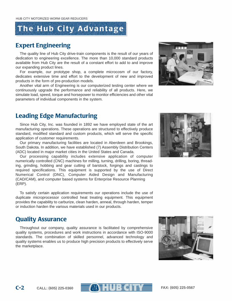
Since Hub City, Inc. was founded in 1892 we have employed state of the artmanufacturing operations. These operations are structured to effectively producestandard, modified standard and custom products, which will serve the specificapplication of customer requirements.
Our primary manufacturing facilities are located in Aberdeen and Brookings,South Dakota. In addition, we have established (7) Assembly Distribution Centers(ADC) located in major market cities in the United States and Canada.
Our processing capability includes extensive application of computernumerically controlled (CNC) machines for milling, turning, drilling, boring, thread-ing, grinding, hobbing and gear cutting of barstock, forgings and castings torequired specifications. This equipment is supported by the use of DirectNumerical Control (DNC), Computer Aided Design and Manufacturing(CAD/CAM), and computer based systems for Enterprise Resource Planning(ERP).
To satisfy certain application requirements our operations include the use ofduplicate microprocessor controlled heat treating equipment. This equipmentprovides the capability to carburize, clean harden, anneal, through harden, temperor induction harden the various materials used in our products.
Th e H u b C i t y Ad va n t a g e
The quality line of Hub City drive-train components is the result of our years ofdedication to engineering excellence. The more than 10,000 standard productsavailable from Hub City are the result of a constant effort to add to and improveour expanding product lines.
For example, our prototype shop, a complete microcosm of our factory, dedicates extensive time and effort to the development of new and improved products in the form of pre-production models.
Another vital arm of Engineering is our computerized testing center where wecontinuously upgrade the performance and reliability of all products. Here, we simulate load, speed, torque and horsepower to monitor efficiencies and other vitalparameters of individual components in the system.
Expert Engineering
Leading Edge Manufacturing
Quality AssuranceThroughout our company, quality assurance is facilitated by comprehensive
quality systems, procedures and work instructions in accordance with ISO-9000standards. The combination of skilled personnel, advanced technology andquality systems enables us to produce high precision products to effectively servethe marketplace.
HUB CITY MOTORIZED WORM GEAR REDUCERS
C-3CALL: (605) 225-0360 FAX: (605) 225-0567
Your direct access to the Hub CIty product lines is through a Hub City Customer Service Representative. Incomingphone lines are fully dedicated to Customer Service where trained personnel have up-to-the-minute information on allproducts listed on computer terminal CRTs.
Customer Service offers rapid order processing in-house, daily availability updates plus instant price and deliveryquotes on all standard products.
Fully qualified engineering personnel are also available for design and application counsel through Customer Service.
C u s t o m e r S e r v i c e
Wa r ra n t y
H ow To O rd e r
Hub City Inc. warrants product to be free from defect in material and workmanship for one year from date ofshipment. The company will repair or replace, F.O.B. shipping point, any item found to be defective upon inspection atHub City’s factory in Aberdeen, South Dakota within one year from date of shipment. See Terms and Conditions of Saleon pages C-61 and C-62 for complete warranty and limitation of liability statement.
When ordering a Motorized Worm Gear Reducer it is necessary to select a reducer size (series), model, gear ratio,assembly style, and motor description. If accessories are required, they must be ordered separately and in addition tothe reducer.
Orders may be placed by mail, telephone, fax or e-mail.
Hub City Inc.2914 Industrial A venue
P.O. Box 1089Aber deen, SD 57402-1089
Telephone: 605/225-0360 Fax: 605/225-0567E-Mail: [email protected] Website: www.hubcityinc.com
The following models are also readily available as motorized reducers.Refer to Worm Gear Drives Catalog for reducer dimensions.
Hollow Bore Side Mount: 186, 216, 266, 326, 386, 456, 526, 1806, 2106,2606, 3206, 3806, 4506, 5206.
Drop Bearing Flange: 328, 388, 458, 528, 3208, 3808, 4508, 5208.
Vertical Mounting: 180V, 210V, 260V, 320V, 380V, 450V, 520V, 1810, 2110,2610, 3210, 3810, 4510, 5210.
R e c e s s Ac t i o n Wo r m G e a r i n g
HUB CITY MOTORIZED WORM GEAR REDUCERS
CALL: (605) 225-0360 FAX: (605) 225-0567C-4
With the introduction of High Efficiency motors and the rising cost ofenergy machine designers and equipment builders are demandingequipment and components that operate at higher efficiency levels.HUB CITY has designed their own worm gear speed reducersaround a system of gearing that substantially increases theefficiency. This system is called “RECESS ACTION WORMGEARING”. Recess action worm gearing is a venerable and wellproven gear system. The greatest enemy of worm gearing is heat,heat generated by friction resulting from the rubbing action betweenthe worm and worm gear. By reducing friction an entire series ofbenefits are gained, such as a substantial increase in efficiency,
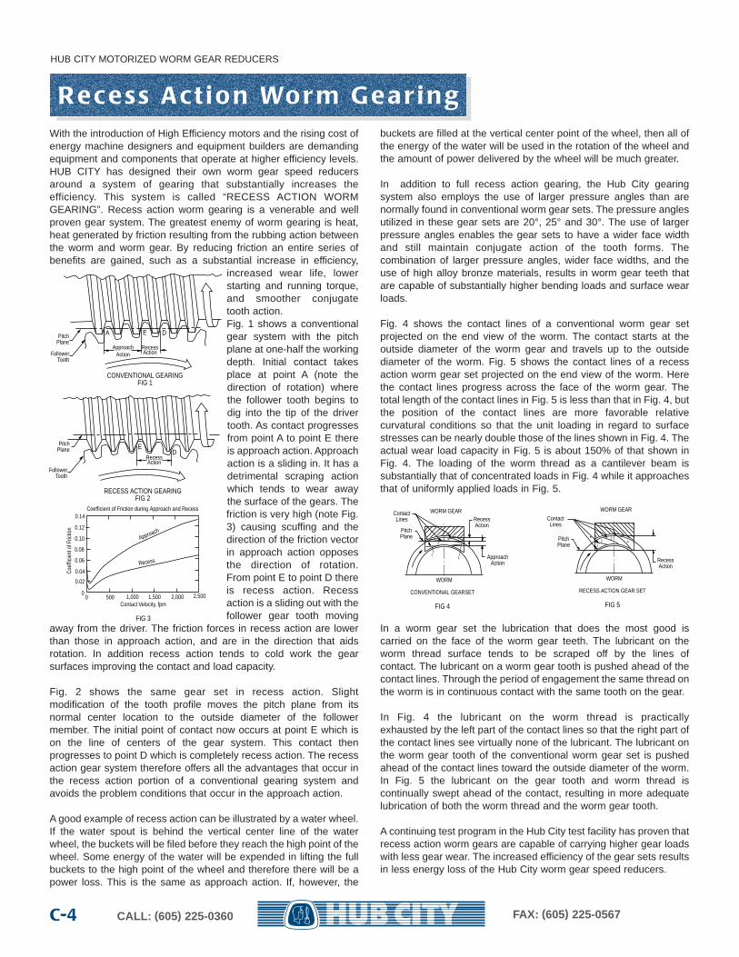
increased wear life, lowerstarting and running torque,and smoother conjugatetooth action.Fig. 1 shows a conventionalgear system with the pitchplane at one-half the workingdepth. Initial contact takesplace at point A (note thedirection of rotation) wherethe follower tooth begins todig into the tip of the drivertooth. As contact progressesfrom point A to point E thereis approach action. Approachaction is a sliding in. It has adetrimental scraping actionwhich tends to wear awaythe surface of the gears. Thefriction is very high (note Fig.3) causing scuffing and thedirection of the friction vectorin approach action opposesthe direction of rotation.From point E to point D thereis recess action. Recessaction is a sliding out with thefollower gear tooth moving
away from the driver. The friction forces in recess action are lowerthan those in approach action, and are in the direction that aidsrotation. In addition recess action tends to cold work the gearsurfaces improving the contact and load capacity.
Fig. 2 shows the same gear set in recess action. Slightmodification of the tooth profile moves the pitch plane from itsnormal center location to the outside diameter of the followermember. The initial point of contact now occurs at point E which ison the line of centers of the gear system. This contact thenprogresses to point D which is completely recess action. The recessaction gear system therefore offers all the advantages that occur inthe recess action portion of a conventional gearing system andavoids the problem conditions that occur in the approach action.
A good example of recess action can be illustrated by a water wheel.If the water spout is behind the vertical center line of the waterwheel, the buckets will be filed before they reach the high point of thewheel. Some energy of the water will be expended in lifting the fullbuckets to the high point of the wheel and therefore there will be apower loss. This is the same as approach action. If, however, the
buckets are filled at the vertical center point of the wheel, then all ofthe energy of the water will be used in the rotation of the wheel andthe amount of power delivered by the wheel will be much greater.
In addition to full recess action gearing, the Hub City gearingsystem also employs the use of larger pressure angles than arenormally found in conventional worm gear sets. The pressure anglesutilized in these gear sets are 20°, 25° and 30°. The use of largerpressure angles enables the gear sets to have a wider face widthand still maintain conjugate action of the tooth forms. Thecombination of larger pressure angles, wider face widths, and theuse of high alloy bronze materials, results in worm gear teeth thatare capable of substantially higher bending loads and surface wearloads.
Fig. 4 shows the contact lines of a conventional worm gear setprojected on the end view of the worm. The contact starts at theoutside diameter of the worm gear and travels up to the outsidediameter of the worm. Fig. 5 shows the contact lines of a recessaction worm gear set projected on the end view of the worm. Herethe contact lines progress across the face of the worm gear. Thetotal length of the contact lines in Fig. 5 is less than that in Fig. 4, butthe position of the contact lines are more favorable relativecurvatural conditions so that the unit loading in regard to surfacestresses can be nearly double those of the lines shown in Fig. 4. Theactual wear load capacity in Fig. 5 is about 150% of that shown inFig. 4. The loading of the worm thread as a cantilever beam issubstantially that of concentrated loads in Fig. 4 while it approachesthat of uniformly applied loads in Fig. 5.
In a worm gear set the lubrication that does the most good iscarried on the face of the worm gear teeth. The lubricant on theworm thread surface tends to be scraped off by the lines ofcontact. The lubricant on a worm gear tooth is pushed ahead of thecontact lines. Through the period of engagement the same thread onthe worm is in continuous contact with the same tooth on the gear.
In Fig. 4 the lubricant on the worm thread is practicallyexhausted by the left part of the contact lines so that the right part ofthe contact lines see virtually none of the lubricant. The lubricant onthe worm gear tooth of the conventional worm gear set is pushedahead of the contact lines toward the outside diameter of the worm.In Fig. 5 the lubricant on the gear tooth and worm thread iscontinually swept ahead of the contact, resulting in more adequatelubrication of both the worm thread and the worm gear tooth.
A continuing test program in the Hub City test facility has proven thatrecess action worm gears are capable of carrying higher gear loadswith less gear wear. The increased efficiency of the gear sets resultsin less energy loss of the Hub City worm gear speed reducers.
A E DPitchPlane
FollowerTooth
ApproachAction
RecessAction
CONVENTIONAL GEARINGFIG 1
ED
PitchPlane
FollowerTooth
RecessAction
RECESS ACTION GEARINGFIG 2
Coe
ffici
ent o
f Fric
tion
Contact Velocity, fpm
FIG 3
Coefficient of Friction during Approach and Recess0.14
0.12
0.10
0.08
0.06
0.04
0.02
00 500 1,000 1,500 2,000 2,500
Approach
Recess
CONVENTIONAL GEARSET
FIG 4
ContactLines
PitchPlane
RecessAction
ApproachAction
WORM GEAR
WORM
11
23
RECESS ACTION GEAR SET
FIG 5
ContactLines
PitchPlane
RecessAction
WORM GEAR
WORM
142
3
E n g i n e e r i n g a n d Ap p l i c a t i o n D a t a
HUB CITY MOTORIZED WORM GEAR REDUCERS
C-5FAX: (605) 225-0567CALL: (605) 225-0360
Before selecting the proper Hub City speed reducer for yourapplication, a review of the basic engineering principles will behelpful.
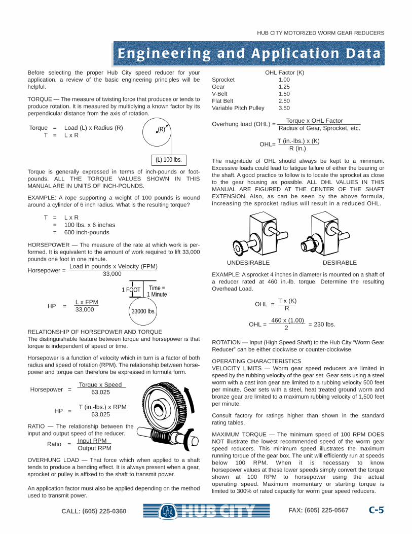
TORQUE — The measure of twisting force that produces or tends toproduce rotation. It is measured by multiplying a known factor by itsperpendicular distance from the axis of rotation.
Torque = Load (L) x Radius (R)T = L x R
Torque is generally expressed in terms of inch-pounds or foot-pounds. ALL THE TORQUE VALUES SHOWN IN THISMANUAL ARE IN UNITS OF INCH-POUNDS.
EXAMPLE: A rope supporting a weight of 100 pounds is woundaround a cylinder of 6 inch radius. What is the resulting torque?
T = L x R= 100 lbs. x 6 inches= 600 inch-pounds
HORSEPOWER — The measure of the rate at which work is per-formed. It is equivalent to the amount of work required to lift 33,000pounds one foot in one minute.
Horsepower =Load in pounds x Velocity (FPM)
33,000
HP =L x FPM33,000
RELATIONSHIP OF HORSEPOWER AND TORQUEThe distinguishable feature between torque and horsepower is thattorque is independent of speed or time.
Horsepower is a function of velocity which in turn is a factor of bothradius and speed of rotation (RPM). The relationship between horse-power and torque can therefore be expressed in formula form.
Torque x SpeedHorsepower = 63,025
T (in.-lbs.) x RPMHP = 63,025
RATIO — The relationship between theinput and output speed of the reducer.
Ratio = Input RPMOutput RPM
OVERHUNG LOAD — That force which when applied to a shafttends to produce a bending effect. It is always present when a gear,sprocket or pulley is affixed to the shaft to transmit power.
An application factor must also be applied depending on the methodused to transmit power.
OHL Factor (K)Sprocket 1.00Gear 1.25V-Belt 1.50Flat Belt 2.50Variable Pitch Pulley 3.50
Overhung load (OHL) = Torque x OHL FactorRadius of Gear, Sprocket, etc.
OHL= T (in.-lbs.) x (K)R (in.)
The magnitude of OHL should always be kept to a minimum.Excessive loads could lead to fatigue failure of either the bearing orthe shaft. A good practice to follow is to locate the sprocket as closeto the gear housing as possible. ALL OHL VALUES IN THISMANUAL ARE FIGURED AT THE CENTER OF THE SHAFTEXTENSION. Also, as can be seen by the above formula,increasing the sprocket radius will result in a reduced OHL.
UNDESIRABLE DESIRABLE
EXAMPLE: A sprocket 4 inches in diameter is mounted on a shaft ofa reducer rated at 460 in.-lb. torque. Determine the resultingOverhead Load.
OHL = T x (K)R
460 x (1.00)OHL = 2 = 230 lbs.
ROTATION — Input (High Speed Shaft) to the Hub City “Worm GearReducer” can be either clockwise or counter-clockwise.
OPERATING CHARACTERISTICSVELOCITY LIMITS — Worm gear speed reducers are limited inspeed by the rubbing velocity of the gear set. Gear sets using a steelworm with a cast iron gear are limited to a rubbing velocity 500 feetper minute. Gear sets with a steel, heat treated ground worm andbronze gear are limited to a maximum rubbing velocity of 1,500 feetper minute.
Consult factory for ratings higher than shown in the standardrating tables.
MAXIMUM TORQUE — The minimum speed of 100 RPM DOESNOT illustrate the lowest recommended speed of the worm gearspeed reducers. This minimum speed illustrates the maximumrunning torque of the gear box. The unit will efficiently run at speedsbelow 100 RPM. When it is necessary to knowhorsepower values at these lower speeds simply convert the torqueshown at 100 RPM to horsepower using the actualoperating speed. Maximum momentary or starting torque islimited to 300% of rated capacity for worm gear speed reducers.
(L) 100 lbs.
(R)
1 FOOT Time =1 Minute
33000 lbs.
R a t i n g Pa ra m e t e r s
HUB CITY MOTORIZED WORM GEAR REDUCERS
CALL: (605) 225-0360 FAX: (605) 225-0567C-6
Mechanical RatingsThe mechanical capacity of a motorized worm gear reducer is generally based on the surface endurance limit of theworm gear material. In some cases the shear strength of the worm gear material may be the limiting factor such as inlow speed, high torque applications. Maximum mechanical ratings are calculated to be used with a service factor of 1.0.This is for continuous service free from shock loading and a total duration of up to 10 hours per day. Applications out-side of these conditions require further modification of the unit mechanical ratings. The selection tables provided showthe required unit size based on mechanical capacity, for service factors from 1.00 to 2.00. Table 1 defines the servicefactor for various applications.
Thermal RatingsThe thermal capacity of a HUB CITY reducer is the actual horsepower (without service factor) which it will transmitcontinuously for 2 or more hours without the temperature exceeding 200° F.
Thermal ratings may be ignored when the continuous operating period does not exceed 2 hours and the shutdownperiod equals or exceeds the operating period. However, when the operating period exceeds 2 hours or the operatingperiod exceeds the shutdown period, thermal ratings must be considered. If the thermal capacity of the unit isexceeded, a larger unit must be chosen or provision made for additional cooling. Design options listed will provideincreased thermal capacity. The selection tables provided show the required unit size based on thermal capacity.
Worm gear units should have a run-in period of about 50 hours. Abnormal heating may occur during this run-in periodand does not necessarily indicate that the unit is beyond thermal capacity unless heating is excessive or continuousbeyond the run-in period.
Thermal Design OptionsAs a result of continuing research and development programs HUB CITY can now offer several design options which willincrease the thermal capacity of our standard line of worm gear reducers. The addition of these options providesadditional options in selecting and applying worm gear reducers.
The design options available are:
1.THE USE OF HUB CITY SYNTHETIC LUBRICANT. HUB CITY lubricant is available in quart containers and isnormally stocked by our authorized distributors. It is recommended that HUB CITY synthetic lubricant be used in allworm gear applications because of its ability to increase the operating efficiency of the drive. The use of HUB CITYsynthetic lubricant can increase thermal capacity from 10% to 15% depending on unit size.
2.FAN COOLING. Cooling fans are available as a factory assembled option for all units from Series 260 through Series520. Series 260 through Series 520 fans are also available as a field installed option. The use of cooling fans willincrease thermal capacity from 10% to 50% depending on unit size and speed.
The design options may be used in combination and will provide compound effects on the thermal capacity of a drive.The selection tables provided clearly illustrate this.
REFER TO PAGES C-54 THRU C-60 FOR IMPORTANT WARNING INFORMATION,LUBRICATION AND MAINTENANCE INSTRUCTIONS.
Pre - S e l e c t i o n I n fo r m a t i o n
HUB CITY MOTORIZED WORM GEAR REDUCERS
C-7CALL: (605) 225-0360 FAX: (605) 225-0567
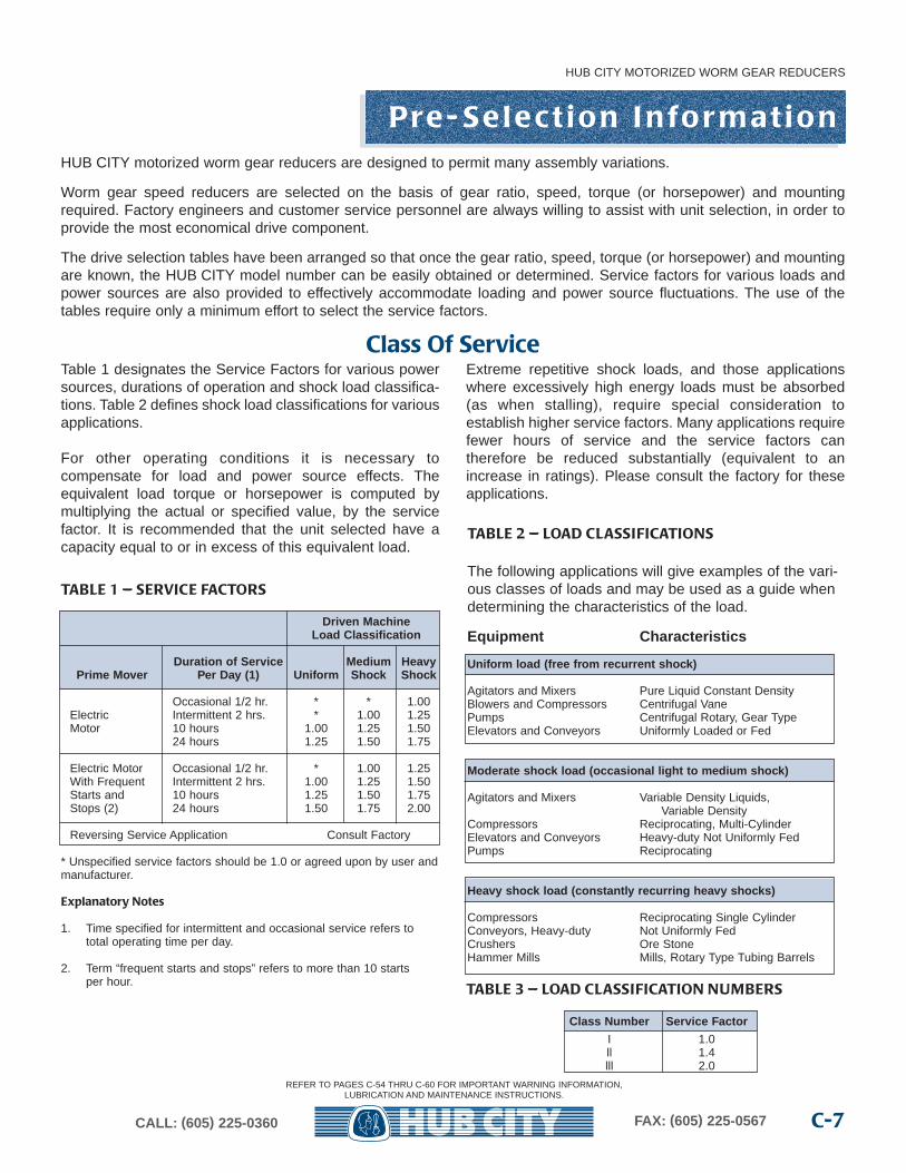
Table 1 designates the Service Factors for various powersources, durations of operation and shock load classifica-tions. Table 2 defines shock load classifications for variousapplications.
For other operating conditions it is necessary tocompensate for load and power source effects. Theequivalent load torque or horsepower is computed bymultiplying the actual or specified value, by the servicefactor. It is recommended that the unit selected have acapacity equal to or in excess of this equivalent load.
Extreme repetitive shock loads, and those applicationswhere excessively high energy loads must be absorbed(as when stalling), require special consideration toestablish higher service factors. Many applications requirefewer hours of service and the service factors can therefore be reduced substantially (equivalent to anincrease in ratings). Please consult the factory for theseapplications.
TABLE 2 — LOAD CLASSIFICATIONS
Class Of Service
HUB CITY motorized worm gear reducers are designed to permit many assembly variations.
Worm gear speed reducers are selected on the basis of gear ratio, speed, torque (or horsepower) and mountingrequired. Factory engineers and customer service personnel are always willing to assist with unit selection, in order toprovide the most economical drive component.
The drive selection tables have been arranged so that once the gear ratio, speed, torque (or horsepower) and mountingare known, the HUB CITY model number can be easily obtained or determined. Service factors for various loads andpower sources are also provided to effectively accommodate loading and power source fluctuations. The use of thetables require only a minimum effort to select the service factors.
REFER TO PAGES C-54 THRU C-60 FOR IMPORTANT WARNING INFORMATION,LUBRICATION AND MAINTENANCE INSTRUCTIONS.
TABLE 1 — SERVICE FACTORS
Driven Mac hineLoad Classification
Duration of Ser vice Medium HeavyPrime Mo ver Per Day (1) Unif orm Shoc k Shoc k
Occasional 1/2 hr. * * 1.00Electric Intermittent 2 hrs. * 1.00 1.25Motor 10 hours 1.00 1.25 1.50
24 hours 1.25 1.50 1.75
Electric Motor Occasional 1/2 hr. * 1.00 1.25With Frequent Intermittent 2 hrs. 1.00 1.25 1.50Starts and 10 hours 1.25 1.50 1.75Stops (2) 24 hours 1.50 1.75 2.00
Reversing Service Application Consult Factory
* Unspecified service factors should be 1.0 or agreed upon by user andmanufacturer.
Explanatory Notes
1. Time specified for intermittent and occasional service refers tototal operating time per day.
2. Term “frequent starts and stops” refers to more than 10 startsper hour.
The following applications will give examples of the vari-ous classes of loads and may be used as a guide whendetermining the characteristics of the load.
Equipment Characteristics
Unif orm load (free fr om recurrent shoc k)
Agitators and Mixers Pure Liquid Constant DensityBlowers and Compressors Centrifugal VanePumps Centrifugal Rotary, Gear TypeElevators and Conveyors Uniformly Loaded or Fed
Moderate shoc k load (occasional light to medium shoc k)
Agitators and Mixers Variable Density Liquids,Variable Density
Compressors Reciprocating, Multi-CylinderElevators and Conveyors Heavy-duty Not Uniformly FedPumps Reciprocating
Heavy shoc k load (constantl y recurring hea vy shoc ks)
Compressors Reciprocating Single CylinderConveyors, Heavy-duty Not Uniformly FedCrushers Ore StoneHammer Mills Mills, Rotary Type Tubing Barrels
TABLE 3 — LOAD CLASSIFICATION NUMBERS
Class Number Service F actor
I 1.0ll 1.4lll 2.0
H ow To S e l e c t An d O rd e r S t a n d a rd M o d e l s
HUB CITY MOTORIZED WORM GEAR REDUCERS
CALL: (605) 225-0360 FAX: (605) 225-0567C-8
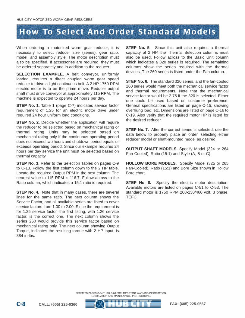
When ordering a motorized worm gear reducer, it isnecessary to select reducer size (series), gear ratio,model, and assembly style. The motor description mustalso be specified. If accessories are required, they mustbe ordered separately and in addition to the reducer.
SELECTION EXAMPLE. A belt conveyor, uniformlyloaded, requires a direct coupled worm gear speedreducer to drive a light continuous belt. A 2 HP 1750 RPMelectric motor is to be the prime move. Reducer outputshaft must drive conveyor at approximately 115 RPM. Themachine is expected to operate 24 hours per day.
STEP No. 1. Table 1 (page C-7) indicates service factorrequirement of 1.25 for an electric motor drive underrequired 24 hour uniform load conditions.
STEP No. 2. Decide whether the application will requirethe reducer to be selected based on mechanical rating orthermal rating. Units may be selected based onmechanical rating only if the continuous operating perioddoes not exceed two hours and shutdown period equals orexceeds operating period. Since our example requires 24hours per day service the unit must be selected based onthermal capacity.
STEP No. 3. Refer to the Selection Tables on pages C-9to C-13. Follow the first column down to the 2 HP table.Locate the required Output RPM in the next column. Thenearest value to 115 RPM is 116.7. Follow across to theRatio column, which indicates a 15:1 ratio is required.
STEP No. 4. Note that in many cases, there are severallines for the same ratio. The next column shows theService Factor, and all available series are listed to coverservice factors from 1.00 to 2.00. Since the requirement isfor 1.25 service factor, the first listing, with 1.26 servicefactor, is the correct one. The next column shows theseries 260 would provide this service factor based onmechanical rating only. The next column showing OutputTorque, indicates the resulting torque with 2 HP input, is884 in-lbs.
STEP No. 5. Since this unit also requires a thermalcapacity of 2 HP, the Thermal Selection columns mustalso be used. Follow across to the Basic Unit columnwhich indicates a 320 series is required. The remainingcolumns show the series required with the thermaldevices. The 260 series is listed under the Fan column.
STEP No. 6. The standard 320 series, and the fan-cooled260 series would meet both the mechanical service factorand thermal requirements. Note that the mechanicalservice factor would be 2.75 if the 320 is selected. Eitherone could be used based on customer preference.General specifications are listed on page C-15, showingoverhung load, etc. Dimensions are listed on page C-16 toC-19. Also verify that the required motor HP is listed forthe desired reducer.
STEP No. 7. After the correct series is selected, use thedata below to properly place an order, selecting eitherreducer model or shaft-mounted model as desired.
OUTPUT SHAFT MODELS. Specify Model (324 or 264Fan-Cooled), Ratio (15:1) and Style (A, B or C).
HOLLOW BORE MODELS. Specify Model (325 or 265Fan-Cooled), Ratio (15:1) and Bore Size shown in HollowBore chart.
STEP No. 8. Specify the electric motor description.Available motors are listed on pages C-51 to C-53. Thestandard motor is 1750 RPM 208-230/460 volt, 3 phase,TEFC.
REFER TO PAGES C-54 THRU C-60 FOR IMPORTANT WARNING INFORMATION,LUBRICATION AND MAINTENANCE INSTRUCTIONS.
HUB CITY MOTORIZED WORM GEAR REDUCERS
C-9CALL: (605) 225-0360 FAX: (605) 225-0567
S i n g l e R e d u c t i o n S e l e c t i o n
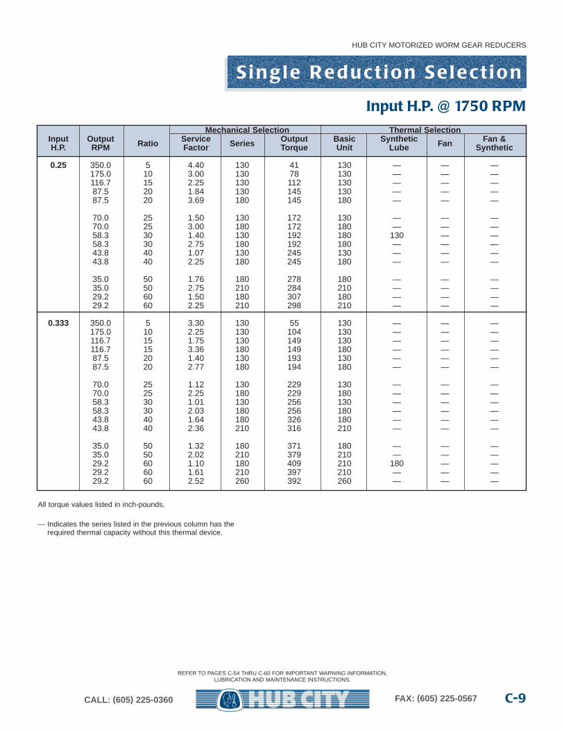
Mechanical Selection Thermal SelectionInput Output Ratio Service Series Output Basic Synthetic Fan Fan &H.P. RPM Factor Torque Unit Lube Synthetic
0.25 350.0 5 4.40 130 41 130 — — —175.0 10 3.00 130 78 130 — — —116.7 15 2.25 130 112 130 — — —87.5 20 1.84 130 145 130 — — —87.5 20 3.69 180 145 180 — — —
70.0 25 1.50 130 172 130 — — —70.0 25 3.00 180 172 180 — — —58.3 30 1.40 130 192 180 130 — —58.3 30 2.75 180 192 180 — — —43.8 40 1.07 130 245 130 — — —43.8 40 2.25 180 245 180 — — —
35.0 50 1.76 180 278 180 — — —35.0 50 2.75 210 284 210 — — —29.2 60 1.50 180 307 180 — — —29.2 60 2.25 210 298 210 — — —
0.333 350.0 5 3.30 130 55 130 — — —175.0 10 2.25 130 104 130 — — —116.7 15 1.75 130 149 130 — — —116.7 15 3.36 180 149 180 — — —87.5 20 1.40 130 193 130 — — —87.5 20 2.77 180 194 180 — — —
70.0 25 1.12 130 229 130 — — —70.0 25 2.25 180 229 180 — — —58.3 30 1.01 130 256 130 — — —58.3 30 2.03 180 256 180 — — —43.8 40 1.64 180 326 180 — — —43.8 40 2.36 210 316 210 — — —
35.0 50 1.32 180 371 180 — — —35.0 50 2.02 210 379 210 — — —29.2 60 1.10 180 409 210 180 — —29.2 60 1.61 210 397 210 — — —29.2 60 2.52 260 392 260 — — —
All torque values listed in inch-pounds.
— Indicates the series listed in the previous column has the required thermal capacity without this thermal device.
Input H.P. @ 1750 RPM
REFER TO PAGES C-54 THRU C-60 FOR IMPORTANT WARNING INFORMATION,LUBRICATION AND MAINTENANCE INSTRUCTIONS.
S i n g l e R e d u c t i o n S e l e c t i o n
HUB CITY MOTORIZED WORM GEAR REDUCERS
CALL: (605) 225-0360 FAX: (605) 225-0567C-10
All torque values listed in inch-pounds.
— Indicates the series listed in the previous column has the required thermal capacity without this thermal device.
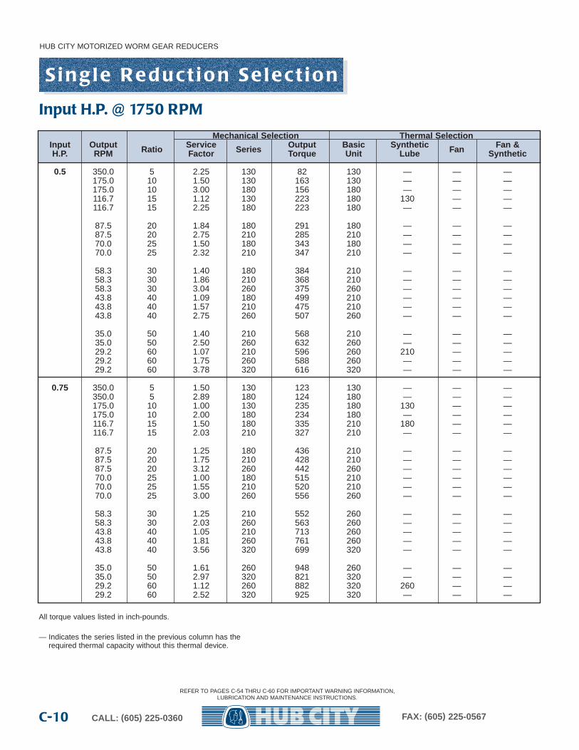
Mechanical Selection Thermal SelectionInput Output Ratio Service Series Output Basic Synthetic Fan Fan &H.P. RPM Factor Torque Unit Lube Synthetic
0.5 350.0 5 2.25 130 82 130 — — —175.0 10 1.50 130 163 130 — — —175.0 10 3.00 180 156 180 — — —116.7 15 1.12 130 223 180 130 — —116.7 15 2.25 180 223 180 — — —
87.5 20 1.84 180 291 180 — — —87.5 20 2.75 210 285 210 — — —70.0 25 1.50 180 343 180 — — —70.0 25 2.32 210 347 210 — — —
58.3 30 1.40 180 384 210 — — —58.3 30 1.86 210 368 210 — — —58.3 30 3.04 260 375 260 — — —43.8 40 1.09 180 499 210 — — —43.8 40 1.57 210 475 210 — — —43.8 40 2.75 260 507 260 — — —
35.0 50 1.40 210 568 210 — — —35.0 50 2.50 260 632 260 — — —29.2 60 1.07 210 596 260 210 — —29.2 60 1.75 260 588 260 — — —29.2 60 3.78 320 616 320 — — —
0.75 350.0 5 1.50 130 123 130 — — —350.0 5 2.89 180 124 180 — — —175.0 10 1.00 130 235 180 130 — —175.0 10 2.00 180 234 180 — — —116.7 15 1.50 180 335 210 180 — —116.7 15 2.03 210 327 210 — — —
87.5 20 1.25 180 436 210 — — —87.5 20 1.75 210 428 210 — — —87.5 20 3.12 260 442 260 — — —70.0 25 1.00 180 515 210 — — —70.0 25 1.55 210 520 210 — — —70.0 25 3.00 260 556 260 — — —
58.3 30 1.25 210 552 260 — — —58.3 30 2.03 260 563 260 — — —43.8 40 1.05 210 713 260 — — —43.8 40 1.81 260 761 260 — — —43.8 40 3.56 320 699 320 — — —
35.0 50 1.61 260 948 260 — — —35.0 50 2.97 320 821 320 — — —29.2 60 1.12 260 882 320 260 — —29.2 60 2.52 320 925 320 — — —
Input H.P. @ 1750 RPM
REFER TO PAGES C-54 THRU C-60 FOR IMPORTANT WARNING INFORMATION,LUBRICATION AND MAINTENANCE INSTRUCTIONS.
S i n g l e R e d u c t i o n S e l e c t i o n
HUB CITY MOTORIZED WORM GEAR REDUCERS
C-11CALL: (605) 225-0360 FAX: (605) 225-0567
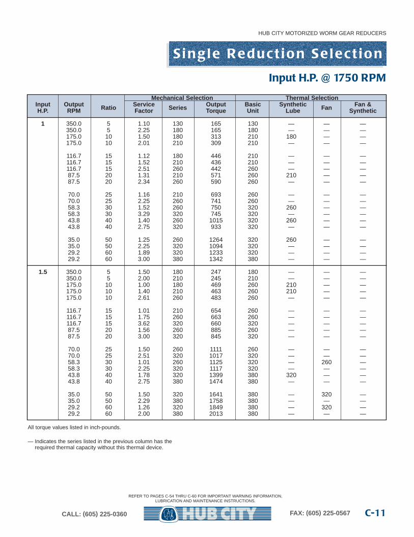
All torque values listed in inch-pounds.
— Indicates the series listed in the previous column has the required thermal capacity without this thermal device.
Mechanical Selection Thermal SelectionInput Output Ratio Service Series Output Basic Synthetic Fan Fan &H.P. RPM Factor Torque Unit Lube Synthetic
1 350.0 5 1.10 130 165 130 — — —350.0 5 2.25 180 165 180 — — —175.0 10 1.50 180 313 210 180 — —175.0 10 2.01 210 309 210 — — —
116.7 15 1.12 180 446 210 — — —116.7 15 1.52 210 436 210 — — —116.7 15 2.51 260 442 260 — — —87.5 20 1.31 210 571 260 210 — —87.5 20 2.34 260 590 260 — — —
70.0 25 1.16 210 693 260 — — —70.0 25 2.25 260 741 260 — — —58.3 30 1.52 260 750 320 260 — —58.3 30 3.29 320 745 320 — — —43.8 40 1.40 260 1015 320 260 — —43.8 40 2.75 320 933 320 — — —
35.0 50 1.25 260 1264 320 260 — —35.0 50 2.25 320 1094 320 — — —29.2 60 1.89 320 1233 320 — — —29.2 60 3.00 380 1342 380 — — —
1.5 350.0 5 1.50 180 247 180 — — —350.0 5 2.00 210 245 210 — — —175.0 10 1.00 180 469 260 210 — —175.0 10 1.40 210 463 260 210 — —175.0 10 2.61 260 483 260 — — —
116.7 15 1.01 210 654 260 — — —116.7 15 1.75 260 663 260 — — —116.7 15 3.62 320 660 320 — — —87.5 20 1.56 260 885 260 — — —87.5 20 3.00 320 845 320 — — —
70.0 25 1.50 260 1111 260 — — —70.0 25 2.51 320 1017 320 — — —58.3 30 1.01 260 1125 320 — 260 —58.3 30 2.25 320 1117 320 — — —43.8 40 1.78 320 1399 380 320 — —43.8 40 2.75 380 1474 380 — — —
35.0 50 1.50 320 1641 380 — 320 —35.0 50 2.29 380 1758 380 — — —29.2 60 1.26 320 1849 380 — 320 —29.2 60 2.00 380 2013 380 — — —
Input H.P. @ 1750 RPM
REFER TO PAGES C-54 THRU C-60 FOR IMPORTANT WARNING INFORMATION,LUBRICATION AND MAINTENANCE INSTRUCTIONS.
S i n g l e R e d u c t i o n S e l e c t i o n
HUB CITY MOTORIZED WORM GEAR REDUCERS
CALL: (605) 225-0360 FAX: (605) 225-0567C-12
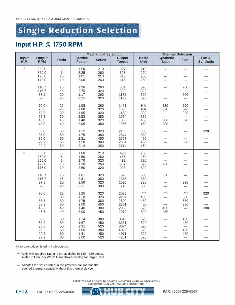
All torque values listed in inch-pounds.
*** Unit with required rating is not available in 130 - 520 series.Refer to Hub City Worm Gear Drives catalog for larger units.
— Indicates the series listed in the previous column has the required thermal capacity without this thermal device.
Mechanical Selection Thermal SelectionInput Output Ratio Service Series Output Basic Synthetic Fan Fan &H.P. RPM Factor Torque Unit Lube Synthetic
2 350.0 5 1.50 210 327 210 — — —350.0 5 2.25 260 323 260 — — —175.0 10 1.01 210 618 260 — — —175.0 10 2.00 260 645 260 — — —
116.7 15 1.26 260 884 320 — 260 —116.7 15 2.75 320 880 320 — — —87.5 20 1.17 260 1179 320 — 260 —87.5 20 2.25 320 1127 320 — — —
70.0 25 1.08 260 1481 NA 320 260 —70.0 25 1.88 320 1356 NA 320 — —58.3 30 1.65 320 1489 380 — 320 —58.3 30 2.53 380 1534 380 — — —43.8 40 1.40 320 1865 450 380 320 —43.8 40 2.05 380 1966 450 380 — —
35.0 50 1.12 320 2188 380 — — 32035.0 50 1.75 380 2344 380 — — —35.0 50 2.51 450 2367 450 — — —29.2 60 1.50 380 2684 450 — 380 —29.2 60 2.12 450 2714 450 — — —
3 350.0 5 1.00 210 490 260 — — —350.0 5 1.50 260 485 260 — — —350.0 5 3.70 320 492 320 — — —175.0 10 1.30 260 967 320 260 — —175.0 10 2.50 320 928 320 — — —
116.7 15 1.81 320 1320 380 320 — —116.7 15 2.81 380 1335 380 — — —87.5 20 1.50 320 1690 380 — 320 —87.5 20 2.31 380 1745 380 — — —
70.0 25 1.25 320 2035 *** *** *** 32058.3 30 1.10 320 2234 450 — 380 —58.3 30 1.75 380 2300 450 — 380 —58.3 30 2.50 450 2301 450 — 380 —43.8 40 1.40 380 2963 520 450 — 38043.8 40 2.00 450 2970 520 450 — —
35.0 50 1.14 380 3516 520 — 450 —35.0 50 1.67 450 3551 520 — 450 —35.0 50 2.31 520 3674 520 — — —29.2 60 1.00 380 4026 520 — 450 —29.2 60 1.41 450 4071 520 — 450 —29.2 60 2.00 520 4251 520 — — —
Input H.P. @ 1750 RPM
REFER TO PAGES C-54 THRU C-60 FOR IMPORTANT WARNING INFORMATION,LUBRICATION AND MAINTENANCE INSTRUCTIONS.
S i n g l e R e d u c t i o n S e l e c t i o n
HUB CITY MOTORIZED WORM GEAR REDUCERS
C-13CALL: (605) 225-0360 FAX: (605) 225-0567
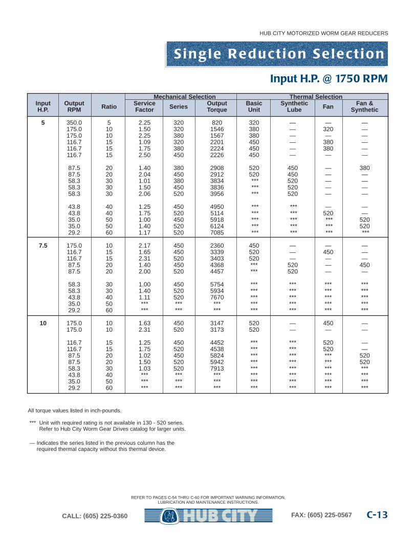
All torque values listed in inch-pounds.
*** Unit with required rating is not available in 130 - 520 series.Refer to Hub City Worm Gear Drives catalog for larger units.
— Indicates the series listed in the previous column has the required thermal capacity without this thermal device.
Mechanical Selection Thermal SelectionInput Output Ratio Service Series Output Basic Synthetic Fan Fan &H.P. RPM Factor Torque Unit Lube Synthetic
5 350.0 5 2.25 320 820 320 — — —175.0 10 1.50 320 1546 380 — 320 —175.0 10 2.25 380 1567 380 — — —116.7 15 1.09 320 2201 450 — 380 —116.7 15 1.75 380 2224 450 — 380 —116.7 15 2.50 450 2226 450 — — —
87.5 20 1.40 380 2908 520 450 — 38087.5 20 2.04 450 2912 520 450 — —58.3 30 1.01 380 3834 *** 520 — —58.3 30 1.50 450 3836 *** 520 — —58.3 30 2.06 520 3956 *** 520 — —
43.8 40 1.25 450 4950 *** *** — —43.8 40 1.75 520 5114 *** *** 520 —35.0 50 1.00 450 5918 *** *** *** 52035.0 50 1.40 520 6124 *** *** *** 52029.2 60 1.17 520 7085 *** *** *** ***
7.5 175.0 10 2.17 450 2360 450 — — —116.7 15 1.65 450 3339 520 — 450 —116.7 15 2.31 520 3403 520 — — —87.5 20 1.40 450 4368 *** 520 — 45087.5 20 2.00 520 4457 *** 520 — —
58.3 30 1.00 450 5754 *** *** *** ***58.3 30 1.40 520 5934 *** *** *** ***43.8 40 1.11 520 7670 *** *** *** ***35.0 50 *** *** *** *** *** *** ***29.2 60 *** *** *** *** *** *** ***
10 175.0 10 1.63 450 3147 520 — 450 —175.0 10 2.31 520 3173 520 — — —
116.7 15 1.25 450 4452 *** *** 520 —116.7 15 1.75 520 4538 *** *** 520 —87.5 20 1.02 450 5824 *** *** *** 52087.5 20 1.50 520 5942 *** *** *** 52058.3 30 1.03 520 7913 *** *** *** ***43.8 40 *** *** *** *** *** *** ***35.0 50 *** *** *** *** *** *** ***29.2 60 *** *** *** *** *** *** ***
Input H.P. @ 1750 RPM
REFER TO PAGES C-54 THRU C-60 FOR IMPORTANT WARNING INFORMATION,LUBRICATION AND MAINTENANCE INSTRUCTIONS.
HUB CITY MOTORIZED WORM GEAR REDUCERS
CALL: (605) 225-0360 FAX: (605) 225-0567C-14
S i n g l e R e d u c t i o n
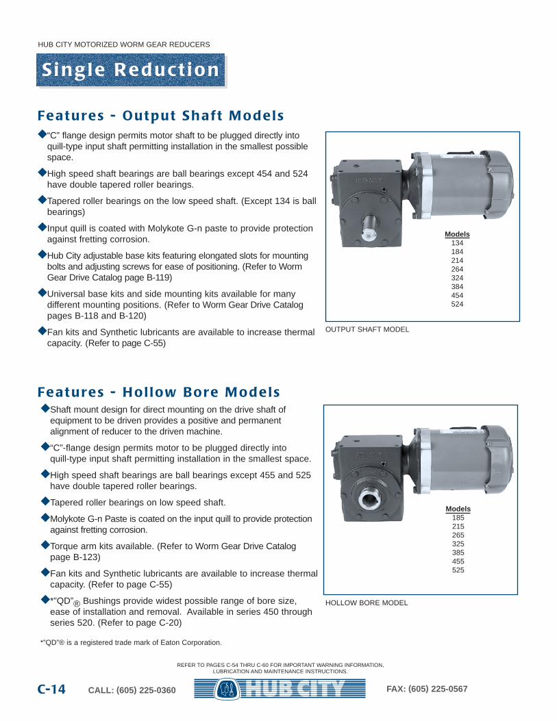
Fe a t u re s - O u t p u t S h a f t M o d e l s
OUTPUT SHAFT MODEL
Fe a t u re s - H o l l ow B o re M o d e l s
HOLLOW BORE MODEL
Models134184214264324384454524
◆ “C” flange design permits motor shaft to be plugged directly intoquill-type input shaft permitting installation in the smallest possiblespace.
◆ High speed shaft bearings are ball bearings except 454 and 524have double tapered roller bearings.
◆ Tapered roller bearings on the low speed shaft. (Except 134 is ballbearings)
◆ Input quill is coated with Molykote G-n paste to provide protectionagainst fretting corrosion.
◆ Hub City adjustable base kits featuring elongated slots for mountingbolts and adjusting screws for ease of positioning. (Refer to WormGear Drive Catalog page B-119)
◆ Universal base kits and side mounting kits available for many different mounting positions. (Refer to Worm Gear Drive Catalogpages B-118 and B-120)
◆ Fan kits and Synthetic lubricants are available to increase thermalcapacity. (Refer to page C-55)
◆ Shaft mount design for direct mounting on the drive shaft ofequipment to be driven provides a positive and permanent alignment of reducer to the driven machine.
◆ “C”-flange design permits motor to be plugged directly intoquill-type input shaft permitting installation in the smallest space.
◆ High speed shaft bearings are ball bearings except 455 and 525have double tapered roller bearings.
◆ Tapered roller bearings on low speed shaft.
◆ Molykote G-n Paste is coated on the input quill to provide protectionagainst fretting corrosion.
◆ Torque arm kits available. (Refer to Worm Gear Drive Catalog page B-123)
◆ Fan kits and Synthetic lubricants are available to increase thermalcapacity. (Refer to page C-55)
◆ *”QD”® Bushings provide widest possible range of bore size,ease of installation and removal. Available in series 450 throughseries 520. (Refer to page C-20)
*”QD”® is a registered trade mark of Eaton Corporation.
Models185215265325385455525
REFER TO PAGES C-54 THRU C-60 FOR IMPORTANT WARNING INFORMATION,LUBRICATION AND MAINTENANCE INSTRUCTIONS.
S i n g l e R e d u c t i o n G e n e ra l S p e c i f i c a t i o n s
HUB CITY MOTORIZED WORM GEAR REDUCERS
C-15CALL: (605) 225-0360 FAX: (605) 225-0567
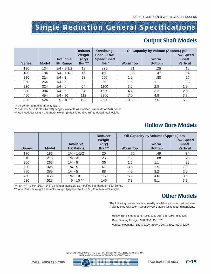
Reducer Overhung Oil Capacity b y Volume (Appr ox.) ptsWeight Load - Lo w Low Speed
Availab le (dry) Speed Shaft Worm ShaftSeries Model HP Range lbs *** lbs * Worm Top Bottom Vertical
130 134 1/4 - 1-1/2 13 225 .31 .25 .16180 184 1/4 - 1-1/2 16 400 .56 .47 .34210 214 1/4 - 3 23 550 1.2 .88 .75260 264 1/4 - 5 33 850 1.6 1.1 .88320 324 1/4 - 5 64 1100 3.5 2.5 1.9380 384 1/4 - 5 84 1600 4.2 3.2 2.6450 454 1/4 - 10 112 2200 7.0 4.8 3.8520 524 5 - 10 ** 138 2600 10.6 7.5 5.5
* At center point of shaft extension.** 1/4 HP - 3 HP (56C - 145TC) flanges available as modified standards on 520 Series.
*** Add Reducer weight and motor weight (pages C-52 to C-53) to obtain total weight.
Output Shaft Models
Reducer Oil Capacity b y Volume (Appr ox.) ptsWeight Low Speed
Availab le (dry) Worm ShaftSeries Model HP Range lbs *** Worm Top Bottom Vertical
180 185 1/4 - 1-1/2 20 .56 .49 .34210 215 1/4 - 3 25 1.2 .88 .75260 265 1/4 - 5 36 1.6 1.1 .88320 325 1/4 - 5 67 3.5 2.5 1.9380 385 1/4 - 5 88 4.2 3.2 2.6450 455 1/4 - 10 117 5.2 4.0 3.0520 525 5 - 10 ** 145 7.3 5.1 3.8
** 1/4 HP - 3 HP (56C - 145TC) flanges available as modified standards on 520 Series.*** Add Reducer weight and motor weight (pages C-52 to C-53) to obtain total weight.
Hollow Bore Models
The following models are also readily available as motorized reducers.Refer to Hub City Worm Gear Drives Catalog for reducer dimensions.
Hollow Bore Side Mount: 186, 216, 266, 326, 386, 456, 526.
Drop Bearing Flange: 328, 388, 458, 528.
Vertical Mounting: 180V, 210V, 260V, 320V, 380V, 450V, 520V.
Other Models
REFER TO PAGES C-54 THRU C-60 FOR IMPORTANT WARNING INFORMATION,LUBRICATION AND MAINTENANCE INSTRUCTIONS.
HUB CITY MOTORIZED WORM GEAR REDUCERS
CALL: (605) 225-0360 FAX: (605) 225-0567C-16
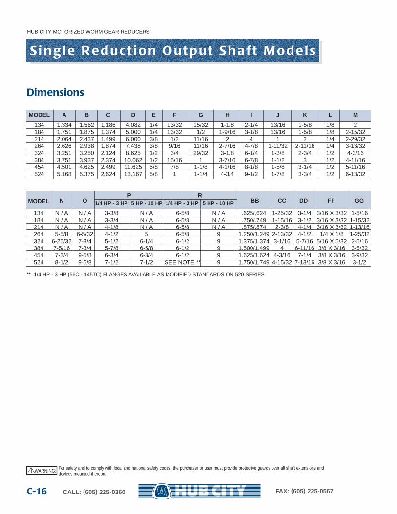
S i n g l e R e d u c t i o n O u t p u t S h a f t M o d e l s
MODEL A B C D E F G H I J K L M
134 1.334 1.562 1.186 4.082 1/4 13/32 15/32 1-1/8 2-1/4 13/16 1-5/8 1/8 2184 1.751 1.875 1.374 5.000 1/4 13/32 1/2 1-9/16 3-1/8 13/16 1-5/8 1/8 2-15/32214 2.064 2.437 1.499 6.000 3/8 1/2 11/16 2 4 1 2 1/4 2-29/32264 2.626 2.938 1.874 7.438 3/8 9/16 11/16 2-7/16 4-7/8 1-11/32 2-11/16 1/4 3-13/32324 3.251 3.250 2.124 8.625 1/2 3/4 29/32 3-1/8 6-1/4 1-3/8 2-3/4 1/2 4-3/16384 3.751 3.937 2.374 10.062 1/2 15/16 1 3-7/16 6-7/8 1-1/2 3 1/2 4-11/16454 4.501 4.625 2.499 11.625 5/8 7/8 1-1/8 4-1/16 8-1/8 1-5/8 3-1/4 1/2 5-11/16524 5.168 5.375 2.624 13.167 5/8 1 1-1/4 4-3/4 9-1/2 1-7/8 3-3/4 1/2 6-13/32
N OP R
BB CC DD FF GGMODEL 1/4 HP - 3 HP 5 HP - 10 HP 1/4 HP - 3 HP 5 HP - 10 HP
134 N / A N / A 3-3/8 N / A 6-5/8 N / A .625/.624 1-25/32 3-1/4 3/16 X 3/32 1-5/16184 N / A N / A 3-3/4 N / A 6-5/8 N / A .750/.749 1-15/16 3-1/2 3/16 X 3/32 1-15/32214 N / A N / A 4-1/8 N / A 6-5/8 N / A .875/.874 2-3/8 4-1/4 3/16 X 3/32 1-13/16264 5-5/8 6-5/32 4-1/2 5 6-5/8 9 1.250/1.249 2-13/32 4-1/2 1/4 X 1/8 1-25/32324 6-25/32 7-3/4 5-1/2 6-1/4 6-1/2 9 1.375/1.374 3-1/16 5-7/16 5/16 X 5/32 2-5/16384 7-5/16 7-3/4 5-7/8 6-5/8 6-1/2 9 1.500/1.499 4 6-11/16 3/8 X 3/16 3-5/32454 7-3/4 9-5/8 6-3/4 6-3/4 6-1/2 9 1.625/1.624 4-3/16 7-1/4 3/8 X 3/16 3-9/32524 8-1/2 9-5/8 7-1/2 7-1/2 SEE NOTE ** 9 1.750/1.749 4-15/32 7-13/16 3/8 X 3/16 3-1/2
** 1/4 HP - 3 HP (56C - 145TC) FLANGES AVAILABLE AS MODIFIED STANDARDS ON 520 SERIES.
Dimensions
WARNING: For safety and to comply with local and national safety codes, the purchaser or user must provide protective guards over all shaft extensions anddevices mounted thereon.
!
HUB CITY MOTORIZED WORM GEAR REDUCERS
C-17CALL: (605) 225-0360 FAX: (605) 225-0567
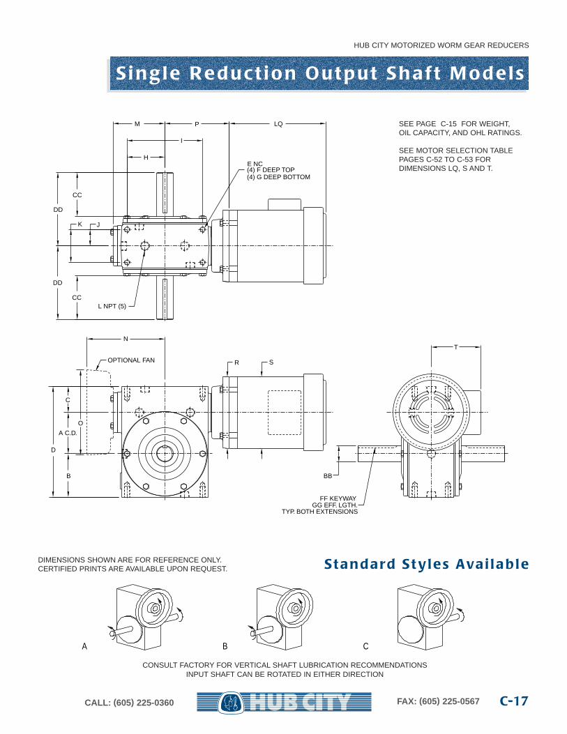
S i n g l e R e d u c t i o n O u t p u t S h a f t M o d e l s
DIMENSIONS SHOWN ARE FOR REFERENCE ONLY.CERTIFIED PRINTS ARE AVAILABLE UPON REQUEST.
A B C
S t a n d a rd S t y l e s Ava i l a b l e
CONSULT FACTORY FOR VERTICAL SHAFT LUBRICATION RECOMMENDATIONSINPUT SHAFT CAN BE ROTATED IN EITHER DIRECTION
H
I
P
JK
CC
DD
FF KEYWAYGG EFF. LGTH.
TYP. BOTH EXTENSIONS
BB
M
E NC(4) F DEEP TOP(4) G DEEP BOTTOM
C
A C.D.
B
D
L NPT (5)
LQ
T
S
N
O
OPTIONAL FAN
DD
CC
R
SEE PAGE C-15 FOR WEIGHT,OIL CAPACITY, AND OHL RATINGS.
SEE MOTOR SELECTION TABLEPAGES C-52 TO C-53 FOR DIMENSIONS LQ, S AND T.
S i n g l e R e d u c t i o n H o l l ow B o re M o d e l s
HUB CITY MOTORIZED WORM GEAR REDUCERS
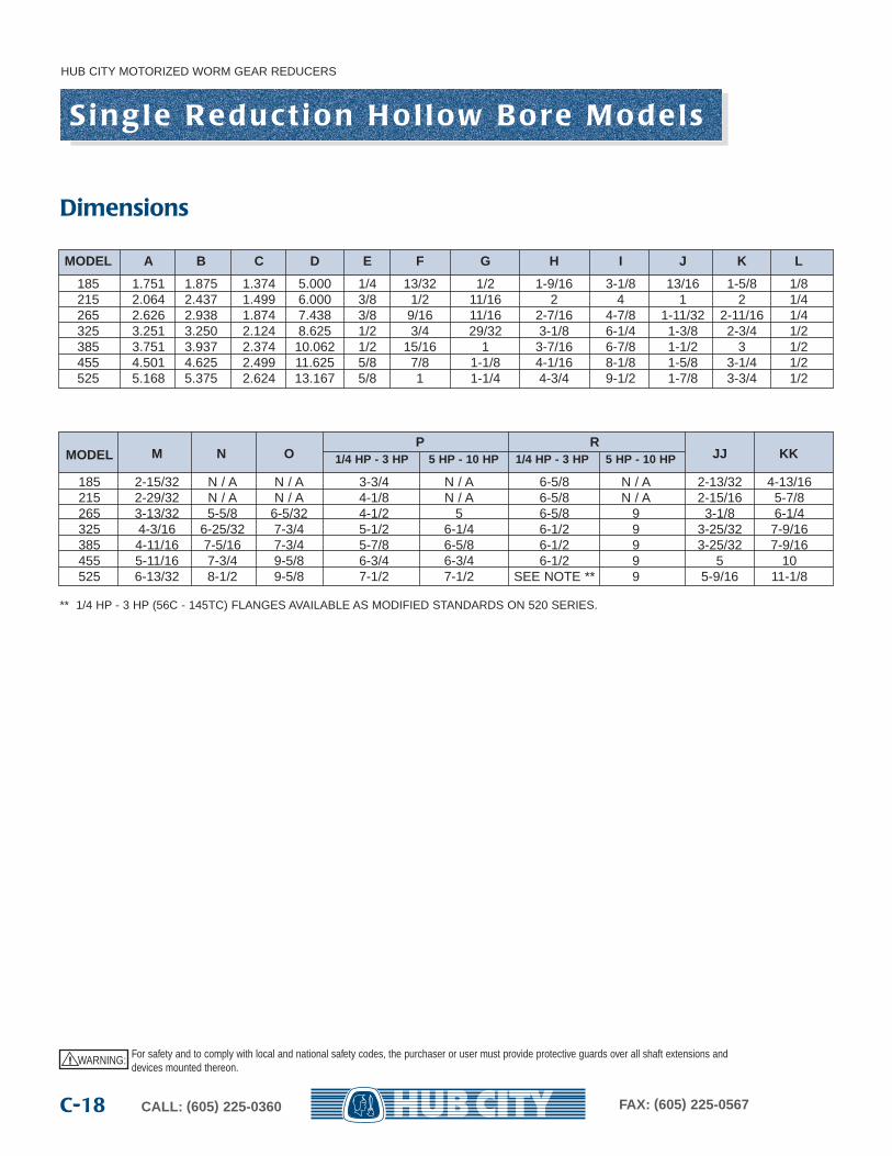
CALL: (605) 225-0360 FAX: (605) 225-0567C-18
MODEL A B C D E F G H I J K L
185 1.751 1.875 1.374 5.000 1/4 13/32 1/2 1-9/16 3-1/8 13/16 1-5/8 1/8215 2.064 2.437 1.499 6.000 3/8 1/2 11/16 2 4 1 2 1/4265 2.626 2.938 1.874 7.438 3/8 9/16 11/16 2-7/16 4-7/8 1-11/32 2-11/16 1/4325 3.251 3.250 2.124 8.625 1/2 3/4 29/32 3-1/8 6-1/4 1-3/8 2-3/4 1/2385 3.751 3.937 2.374 10.062 1/2 15/16 1 3-7/16 6-7/8 1-1/2 3 1/2455 4.501 4.625 2.499 11.625 5/8 7/8 1-1/8 4-1/16 8-1/8 1-5/8 3-1/4 1/2525 5.168 5.375 2.624 13.167 5/8 1 1-1/4 4-3/4 9-1/2 1-7/8 3-3/4 1/2
M N OP R
JJ KKMODEL 1/4 HP - 3 HP 5 HP - 10 HP 1/4 HP - 3 HP 5 HP - 10 HP
185 2-15/32 N / A N / A 3-3/4 N / A 6-5/8 N / A 2-13/32 4-13/16215 2-29/32 N / A N / A 4-1/8 N / A 6-5/8 N / A 2-15/16 5-7/8265 3-13/32 5-5/8 6-5/32 4-1/2 5 6-5/8 9 3-1/8 6-1/4325 4-3/16 6-25/32 7-3/4 5-1/2 6-1/4 6-1/2 9 3-25/32 7-9/16385 4-11/16 7-5/16 7-3/4 5-7/8 6-5/8 6-1/2 9 3-25/32 7-9/16455 5-11/16 7-3/4 9-5/8 6-3/4 6-3/4 6-1/2 9 5 10525 6-13/32 8-1/2 9-5/8 7-1/2 7-1/2 SEE NOTE ** 9 5-9/16 11-1/8
** 1/4 HP - 3 HP (56C - 145TC) FLANGES AVAILABLE AS MODIFIED STANDARDS ON 520 SERIES.
Dimensions
WARNING: For safety and to comply with local and national safety codes, the purchaser or user must provide protective guards over all shaft extensions anddevices mounted thereon.
!
S i n g l e R e d u c t i o n H o l l ow B o re M o d e l s
HUB CITY MOTORIZED WORM GEAR REDUCERS
C-19CALL: (605) 225-0360 FAX: (605) 225-0567
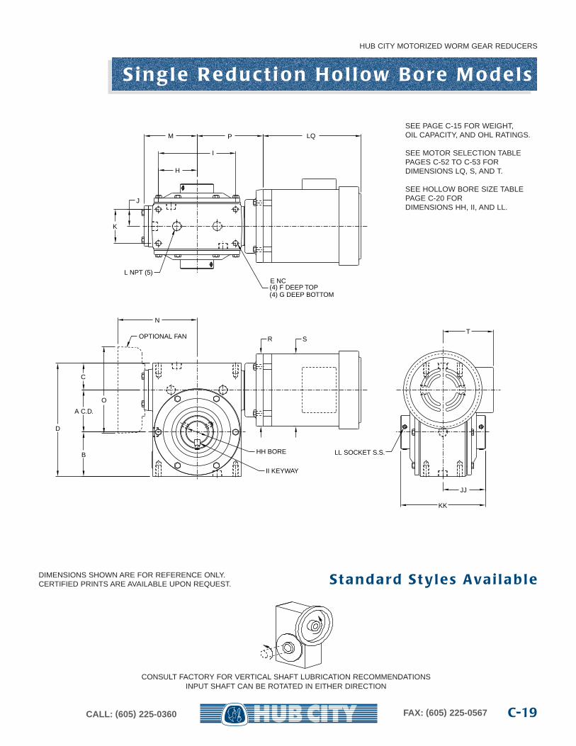
DIMENSIONS SHOWN ARE FOR REFERENCE ONLY.CERTIFIED PRINTS ARE AVAILABLE UPON REQUEST. S t a n d a rd S t y l e s Ava i l a b l e
CONSULT FACTORY FOR VERTICAL SHAFT LUBRICATION RECOMMENDATIONSINPUT SHAFT CAN BE ROTATED IN EITHER DIRECTION
H
I
M P
J
K
JJ
KK
HH BORE
II KEYWAY
LL SOCKET S.S.
L NPT (5)E NC(4) F DEEP TOP(4) G DEEP BOTTOM
LQ
ST
OPTIONAL FAN
N
O
D
A C.D.
B
C
R
SEE PAGE C-15 FOR WEIGHT,OIL CAPACITY, AND OHL RATINGS.
SEE MOTOR SELECTION TABLEPAGES C-52 TO C-53 FOR DIMENSIONS LQ, S, AND T.
SEE HOLLOW BORE SIZE TABLEPAGE C-20 FOR DIMENSIONS HH, II, AND LL.
HUB CITY MOTORIZED WORM GEAR REDUCERS
CALL: (605) 225-0360 FAX: (605) 225-0567C-20
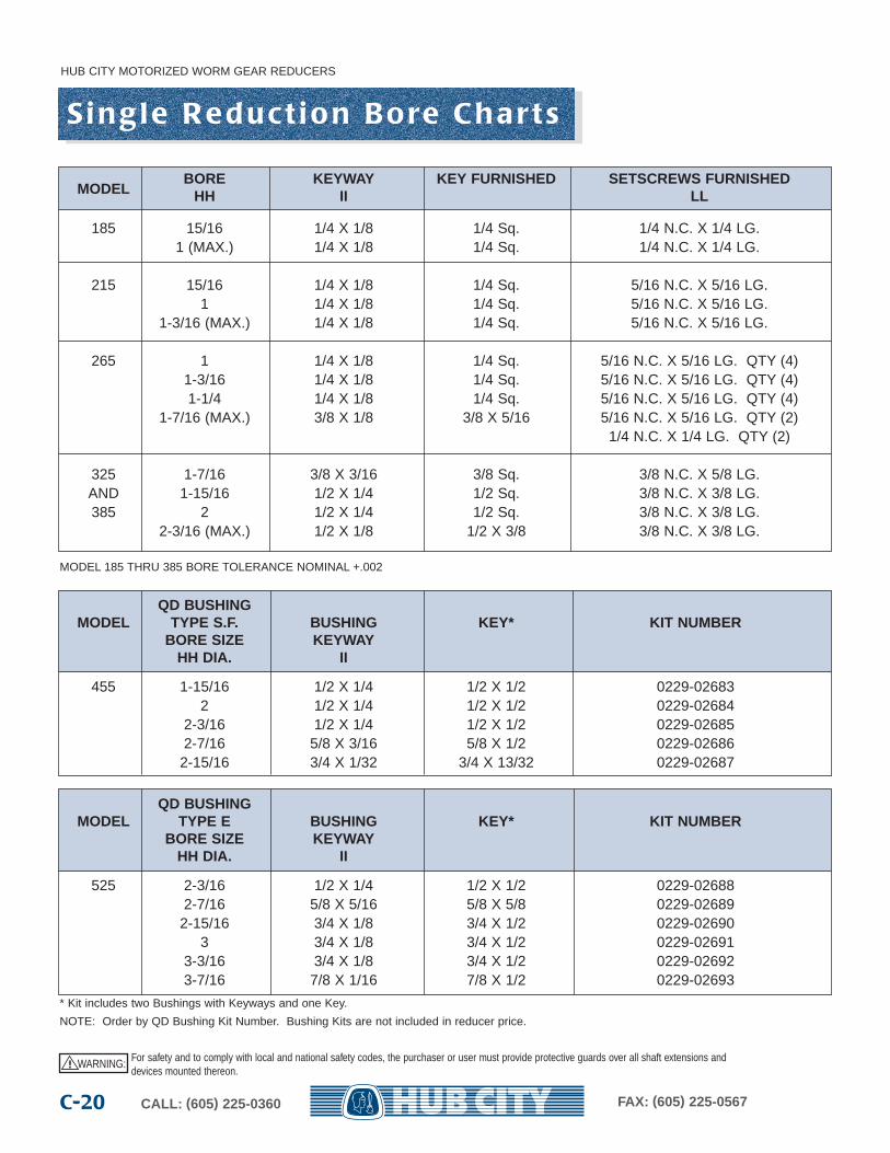
S i n g l e R e d u c t i o n B o re C h a r t s
MODELBORE KEYWAY KEY FURNISHED SETSCREWS FURNISHED
HH II LL
185 15/16 1/4 X 1/8 1/4 Sq. 1/4 N.C. X 1/4 LG.1 (MAX.) 1/4 X 1/8 1/4 Sq. 1/4 N.C. X 1/4 LG.
215 15/16 1/4 X 1/8 1/4 Sq. 5/16 N.C. X 5/16 LG.1 1/4 X 1/8 1/4 Sq. 5/16 N.C. X 5/16 LG.
1-3/16 (MAX.) 1/4 X 1/8 1/4 Sq. 5/16 N.C. X 5/16 LG.
265 1 1/4 X 1/8 1/4 Sq. 5/16 N.C. X 5/16 LG. QTY (4)1-3/16 1/4 X 1/8 1/4 Sq. 5/16 N.C. X 5/16 LG. QTY (4)1-1/4 1/4 X 1/8 1/4 Sq. 5/16 N.C. X 5/16 LG. QTY (4)
1-7/16 (MAX.) 3/8 X 1/8 3/8 X 5/16 5/16 N.C. X 5/16 LG. QTY (2) 1/4 N.C. X 1/4 LG. QTY (2)
325 1-7/16 3/8 X 3/16 3/8 Sq. 3/8 N.C. X 5/8 LG.AND 1-15/16 1/2 X 1/4 1/2 Sq. 3/8 N.C. X 3/8 LG.385 2 1/2 X 1/4 1/2 Sq. 3/8 N.C. X 3/8 LG.
2-3/16 (MAX.) 1/2 X 1/8 1/2 X 3/8 3/8 N.C. X 3/8 LG.
QD BUSHINGMODEL TYPE S.F. BUSHING KEY* KIT NUMBER
BORE SIZE KEYWAYHH DIA. II
455 1-15/16 1/2 X 1/4 1/2 X 1/2 0229-026832 1/2 X 1/4 1/2 X 1/2 0229-02684
2-3/16 1/2 X 1/4 1/2 X 1/2 0229-026852-7/16 5/8 X 3/16 5/8 X 1/2 0229-02686
2-15/16 3/4 X 1/32 3/4 X 13/32 0229-02687
QD BUSHINGMODEL TYPE E BUSHING KEY* KIT NUMBER
BORE SIZE KEYWAYHH DIA. II
525 2-3/16 1/2 X 1/4 1/2 X 1/2 0229-026882-7/16 5/8 X 5/16 5/8 X 5/8 0229-02689
2-15/16 3/4 X 1/8 3/4 X 1/2 0229-026903 3/4 X 1/8 3/4 X 1/2 0229-02691
3-3/16 3/4 X 1/8 3/4 X 1/2 0229-026923-7/16 7/8 X 1/16 7/8 X 1/2 0229-02693
MODEL 185 THRU 385 BORE TOLERANCE NOMINAL +.002
* Kit includes two Bushings with Keyways and one Key.
NOTE: Order by QD Bushing Kit Number. Bushing Kits are not included in reducer price.
WARNING: For safety and to comply with local and national safety codes, the purchaser or user must provide protective guards over all shaft extensions anddevices mounted thereon.
!
D o u b l e R e d u c t i o n S e l e c t i o n
HUB CITY MOTORIZED WORM GEAR REDUCERS
C-21CALL: (605) 225-0360 FAX: (605) 225-0567
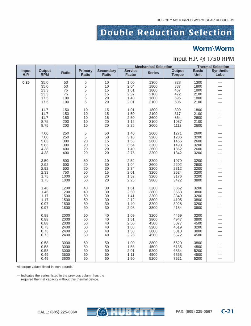
All torque values listed in inch-pounds.
— Indicates the series listed in the previous column has the required thermal capacity without this thermal device.
Mechanical Selection Thermal SelectionInput Output Ratio Primar y Secondar y Service Series Output Basic SyntheticH.P. RPM Ratio Ratio Factor Torque Unit Lube
0.25 35.0 50 5 10 1.00 1300 328 1300 —35.0 50 5 10 2.04 1800 337 1800 —23.3 75 5 15 1.61 1800 467 1800 —23.3 75 5 15 2.37 2100 472 2100 —17.5 100 5 20 1.40 1800 595 1800 —17.5 100 5 20 2.01 2100 606 2100 —
11.7 150 10 15 1.01 1800 809 1800 —11.7 150 10 15 1.50 2100 817 2100 —11.7 150 10 15 2.50 2600 864 2600 —8.75 200 10 20 1.15 2100 1037 2100 —8.75 200 10 20 2.25 2600 1112 2600 —
7.00 250 5 50 1.40 2600 1271 2600 —7.00 250 5 50 3.10 3200 1206 3200 —5.83 300 20 15 1.53 2600 1456 2600 —5.83 300 20 15 3.54 3200 1493 3200 —4.38 400 20 20 1.40 2600 1862 2600 —4.38 400 20 20 2.75 3200 1842 3200 —
3.50 500 50 10 2.52 3200 1979 3200 —2.92 600 20 30 1.04 2600 2202 2600 —2.92 600 20 30 2.34 3200 2312 3200 —2.33 750 50 15 2.01 3200 2624 3200 —1.75 1000 50 20 1.52 3200 3176 3200 —1.75 1000 50 20 2.25 3800 3422 3800 —
1.46 1200 40 30 1.61 3200 3362 3200 —1.46 1200 40 30 2.50 3800 3568 3800 —1.17 1500 50 30 1.41 3200 3849 3200 —1.17 1500 50 30 2.12 3800 4105 3800 —0.97 1800 60 30 1.40 3200 3928 3200 —0.97 1800 60 30 2.08 3800 4184 3800 —
0.88 2000 50 40 1.09 3200 4469 3200 —0.88 2000 50 40 1.51 3800 4947 3800 —0.88 2000 50 40 2.50 4500 5077 4500 —0.73 2400 60 40 1.08 3200 4519 3200 —0.73 2400 60 40 1.50 3800 5013 3800 —0.73 2400 60 40 2.26 4500 5572 4500 —
0.58 3000 60 50 1.00 3800 5620 3800 —0.58 3000 60 50 1.56 4500 6135 4500 —0.58 3000 60 50 2.01 5200 6834 5200 —0.49 3600 60 60 1.11 4500 6868 4500 —0.49 3600 60 60 1.50 5200 7521 5200 —
Worm\Worm
Input H.P. @ 1750 RPM
D o u b l e R e d u c t i o n S e l e c t i o n
HUB CITY MOTORIZED WORM GEAR REDUCERS
CALL: (605) 225-0360 FAX: (605) 225-0567C-22
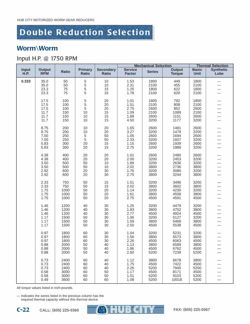
All torque values listed in inch-pounds.
— Indicates the series listed in the previous column has the required thermal capacity without this thermal device.
Mechanical Selection Thermal SelectionInput Output Ratio Primar y Secondar y Service Series Output Basic SyntheticH.P. RPM Ratio Ratio Factor Torque Unit Lube
0.333 35.0 50 5 10 1.53 1800 449 1800 —35.0 50 5 10 2.31 2100 455 2100 —23.3 75 5 15 1.25 1800 622 1800 —23.3 75 5 15 1.78 2100 629 2100 —
17.5 100 5 20 1.01 1800 792 1800 —17.5 100 5 20 1.51 2100 808 2100 —17.5 100 5 20 2.75 2600 852 2600 —11.7 150 10 15 1.09 2100 1089 2100 —11.7 150 10 15 1.88 2600 1151 2600 —11.7 150 10 15 4.50 3200 1177 3200 —
8.75 200 10 20 1.65 2600 1481 2600 —8.75 200 10 20 3.27 3200 1479 3200 —7.00 250 5 50 1.05 2600 1694 2600 —7.00 250 5 50 2.33 3200 1607 3200 —5.83 300 20 15 1.15 2600 1939 2600 —5.83 300 20 15 2.75 3200 1989 3200 —
4.38 400 20 20 1.01 2600 2480 2600 —4.38 400 20 20 2.00 3200 2453 3200 —3.50 500 50 10 1.89 3200 2636 3200 —3.50 500 50 10 2.02 3800 2736 3800 —2.92 600 20 30 1.76 3200 3080 3200 —2.92 600 20 30 2.75 3800 3244 3800 —
2.33 750 50 15 1.51 3200 3496 3200 —2.33 750 50 15 2.02 3800 3602 3800 —1.75 1000 50 20 1.14 3200 4230 3200 —1.75 1000 50 20 1.61 3800 4558 3800 —1.75 1000 50 20 2.75 4500 4591 4500 —
1.46 1200 40 30 1.25 3200 4479 3200 —1.46 1200 40 30 1.83 3800 4752 3800 —1.46 1200 40 30 2.77 4500 4924 4500 —1.17 1500 50 30 1.06 3200 5127 3200 —1.17 1500 50 30 1.59 3800 5468 3800 —1.17 1500 50 30 2.50 4500 5538 4500 —
0.97 1800 60 30 1.04 3200 5231 3200 —0.97 1800 60 30 1.56 3800 5573 3800 —0.97 1800 60 30 2.26 4500 6063 4500 —0.88 2000 50 40 1.13 3800 6589 3800 —0.88 2000 50 40 1.86 4500 6762 4500 —0.88 2000 50 40 2.50 5200 7239 5200 —
0.73 2400 60 40 1.12 3800 6678 3800 —0.73 2400 60 40 1.75 4500 7422 4500 —0.73 2400 60 40 2.26 5200 7945 5200 —0.58 3000 60 50 1.17 4500 8171 4500 —0.58 3000 60 50 1.51 5200 9103 5200 —0.49 3600 60 60 1.08 5200 10018 5200 —
Worm\Worm
Input H.P. @ 1750 RPM
D o u b l e R e d u c t i o n S e l e c t i o n
HUB CITY MOTORIZED WORM GEAR REDUCERS
C-23CALL: (605) 225-0360 FAX: (605) 225-0567
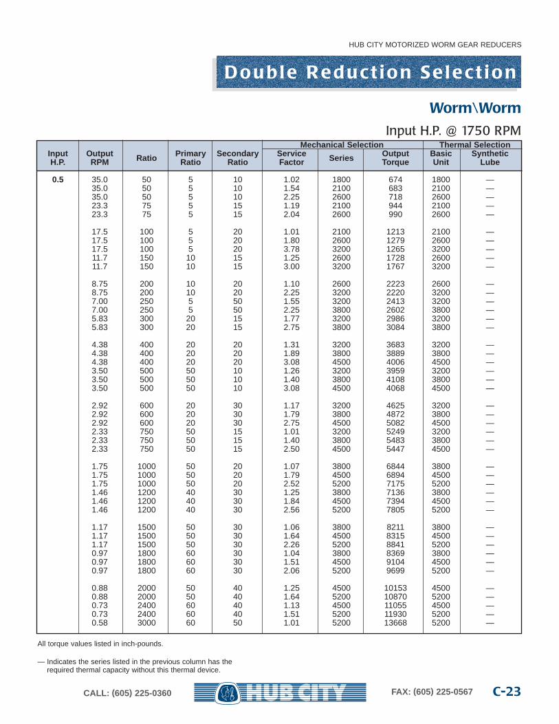
All torque values listed in inch-pounds.
— Indicates the series listed in the previous column has the required thermal capacity without this thermal device.
Mechanical Selection Thermal SelectionInput Output Ratio Primar y Secondar y Service Series Output Basic SyntheticH.P. RPM Ratio Ratio Factor Torque Unit Lube
0.5 35.0 50 5 10 1.02 1800 674 1800 —35.0 50 5 10 1.54 2100 683 2100 —35.0 50 5 10 2.25 2600 718 2600 —23.3 75 5 15 1.19 2100 944 2100 —23.3 75 5 15 2.04 2600 990 2600 —
17.5 100 5 20 1.01 2100 1213 2100 —17.5 100 5 20 1.80 2600 1279 2600 —17.5 100 5 20 3.78 3200 1265 3200 —11.7 150 10 15 1.25 2600 1728 2600 —11.7 150 10 15 3.00 3200 1767 3200 —
8.75 200 10 20 1.10 2600 2223 2600 —8.75 200 10 20 2.25 3200 2220 3200 —7.00 250 5 50 1.55 3200 2413 3200 —7.00 250 5 50 2.25 3800 2602 3800 —5.83 300 20 15 1.77 3200 2986 3200 —5.83 300 20 15 2.75 3800 3084 3800 —
4.38 400 20 20 1.31 3200 3683 3200 —4.38 400 20 20 1.89 3800 3889 3800 —4.38 400 20 20 3.08 4500 4006 4500 —3.50 500 50 10 1.26 3200 3959 3200 —3.50 500 50 10 1.40 3800 4108 3800 —3.50 500 50 10 3.08 4500 4068 4500 —
2.92 600 20 30 1.17 3200 4625 3200 —2.92 600 20 30 1.79 3800 4872 3800 —2.92 600 20 30 2.75 4500 5082 4500 —2.33 750 50 15 1.01 3200 5249 3200 —2.33 750 50 15 1.40 3800 5483 3800 —2.33 750 50 15 2.50 4500 5447 4500 —
1.75 1000 50 20 1.07 3800 6844 3800 —1.75 1000 50 20 1.79 4500 6894 4500 —1.75 1000 50 20 2.52 5200 7175 5200 —1.46 1200 40 30 1.25 3800 7136 3800 —1.46 1200 40 30 1.84 4500 7394 4500 —1.46 1200 40 30 2.56 5200 7805 5200 —
1.17 1500 50 30 1.06 3800 8211 3800 —1.17 1500 50 30 1.64 4500 8315 4500 —1.17 1500 50 30 2.26 5200 8841 5200 —0.97 1800 60 30 1.04 3800 8369 3800 —0.97 1800 60 30 1.51 4500 9104 4500 —0.97 1800 60 30 2.06 5200 9699 5200 —
0.88 2000 50 40 1.25 4500 10153 4500 —0.88 2000 50 40 1.64 5200 10870 5200 —0.73 2400 60 40 1.13 4500 11055 4500 —0.73 2400 60 40 1.51 5200 11930 5200 —0.58 3000 60 50 1.01 5200 13668 5200 —
Worm\Worm
Input H.P. @ 1750 RPM
All torque values listed in inch-pounds.
— Indicates the series listed in the previous column has the required thermal capacity without this thermal device.
D o u b l e R e d u c t i o n S e l e c t i o n
HUB CITY MOTORIZED WORM GEAR REDUCERS
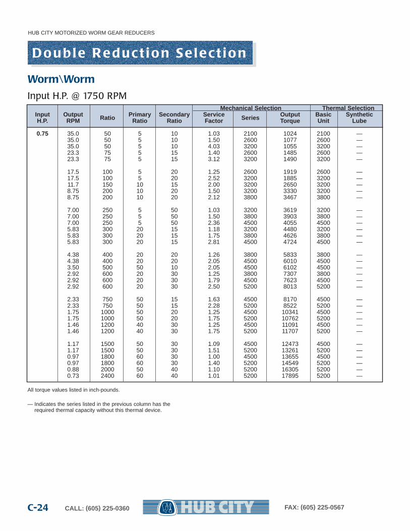
CALL: (605) 225-0360 FAX: (605) 225-0567C-24
Mechanical Selection Thermal SelectionInput Output Ratio Primar y Secondar y Service Series Output Basic SyntheticH.P. RPM Ratio Ratio Factor Torque Unit Lube
0.75 35.0 50 5 10 1.03 2100 1024 2100 —35.0 50 5 10 1.50 2600 1077 2600 —35.0 50 5 10 4.03 3200 1055 3200 —23.3 75 5 15 1.40 2600 1485 2600 —23.3 75 5 15 3.12 3200 1490 3200 —
17.5 100 5 20 1.25 2600 1919 2600 —17.5 100 5 20 2.52 3200 1885 3200 —11.7 150 10 15 2.00 3200 2650 3200 —8.75 200 10 20 1.50 3200 3330 3200 —8.75 200 10 20 2.12 3800 3467 3800 —
7.00 250 5 50 1.03 3200 3619 3200 —7.00 250 5 50 1.50 3800 3903 3800 —7.00 250 5 50 2.36 4500 4055 4500 —5.83 300 20 15 1.18 3200 4480 3200 —5.83 300 20 15 1.75 3800 4626 3800 —5.83 300 20 15 2.81 4500 4724 4500 —
4.38 400 20 20 1.26 3800 5833 3800 —4.38 400 20 20 2.05 4500 6010 4500 —3.50 500 50 10 2.05 4500 6102 4500 —2.92 600 20 30 1.25 3800 7307 3800 —2.92 600 20 30 1.79 4500 7623 4500 —2.92 600 20 30 2.50 5200 8013 5200 —
2.33 750 50 15 1.63 4500 8170 4500 —2.33 750 50 15 2.28 5200 8522 5200 —1.75 1000 50 20 1.25 4500 10341 4500 —1.75 1000 50 20 1.75 5200 10762 5200 —1.46 1200 40 30 1.25 4500 11091 4500 —1.46 1200 40 30 1.75 5200 11707 5200 —
1.17 1500 50 30 1.09 4500 12473 4500 —1.17 1500 50 30 1.51 5200 13261 5200 —0.97 1800 60 30 1.00 4500 13655 4500 —0.97 1800 60 30 1.40 5200 14549 5200 —0.88 2000 50 40 1.10 5200 16305 5200 —0.73 2400 60 40 1.01 5200 17895 5200 —
Worm\Worm
Input H.P. @ 1750 RPM
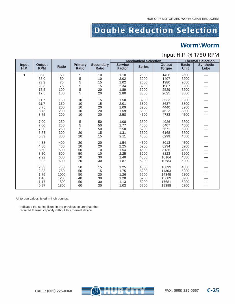
All torque values listed in inch-pounds.
— Indicates the series listed in the previous column has the required thermal capacity without this thermal device.
D o u b l e R e d u c t i o n S e l e c t i o n
HUB CITY MOTORIZED WORM GEAR REDUCERS
C-25CALL: (605) 225-0360 FAX: (605) 225-0567
Mechanical Selection Thermal SelectionInput Output Ratio Primar y Secondar y Service Series Output Basic SyntheticH.P. RPM Ratio Ratio Factor Torque Unit Lube
1 35.0 50 5 10 1.10 2600 1436 2600 —35.0 50 5 10 3.02 3200 1407 3200 —23.3 75 5 15 1.02 2600 1980 2600 —23.3 75 5 15 2.34 3200 1987 3200 —17.5 100 5 20 1.89 3200 2529 3200 —17.5 100 5 20 2.80 3800 2625 3800 —
11.7 150 10 15 1.50 3200 3533 3200 —11.7 150 10 15 2.01 3800 3637 3800 —8.75 200 10 20 1.09 3200 4440 3200 —8.75 200 10 20 1.59 3800 4623 3800 —8.75 200 10 20 2.58 4500 4783 4500 —
7.00 250 5 50 1.08 3800 4926 3800 —7.00 250 5 50 1.77 4500 5407 4500 —7.00 250 5 50 2.50 5200 5671 5200 —5.83 300 20 15 1.31 3800 6168 3800 —5.83 300 20 15 2.11 4500 6299 4500 —
4.38 400 20 20 1.54 4500 8013 4500 —4.38 400 20 20 2.25 5200 8294 5200 —3.50 500 50 10 1.54 4500 8136 4500 —3.50 500 50 10 2.25 5200 8323 5200 —2.92 600 20 30 1.40 4500 10164 4500 —2.92 600 20 30 1.87 5200 10684 5200 —
2.33 750 50 15 1.25 4500 10893 4500 —2.33 750 50 15 1.75 5200 11363 5200 —1.75 1000 50 20 1.26 5200 14349 5200 —1.46 1200 40 30 1.28 5200 15609 5200 —1.17 1500 50 30 1.13 5200 17681 5200 —0.97 1800 60 30 1.03 5200 19398 5200 —
Worm\Worm
Input H.P. @ 1750 RPM
HUB CITY MOTORIZED WORM GEAR REDUCERS
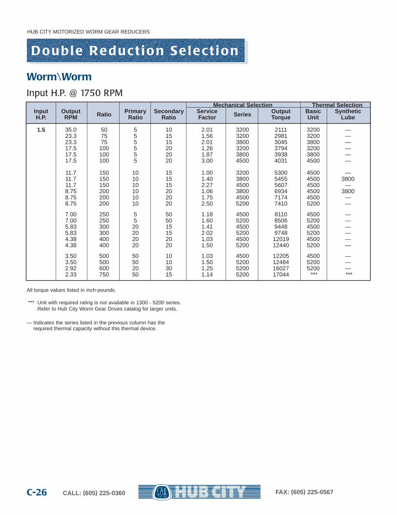
CALL: (605) 225-0360 FAX: (605) 225-0567C-26
D o u b l e R e d u c t i o n S e l e c t i o n
Mechanical Selection Thermal SelectionInput Output Ratio Primar y Secondar y Service Series Output Basic SyntheticH.P. RPM Ratio Ratio Factor Torque Unit Lube
1.5 35.0 50 5 10 2.01 3200 2111 3200 —23.3 75 5 15 1.56 3200 2981 3200 —23.3 75 5 15 2.01 3800 3045 3800 —17.5 100 5 20 1.26 3200 3794 3200 —17.5 100 5 20 1.87 3800 3938 3800 —17.5 100 5 20 3.00 4500 4031 4500 —
11.7 150 10 15 1.00 3200 5300 4500 —11.7 150 10 15 1.40 3800 5455 4500 380011.7 150 10 15 2.27 4500 5607 4500 —8.75 200 10 20 1.06 3800 6934 4500 38008.75 200 10 20 1.75 4500 7174 4500 —8.75 200 10 20 2.50 5200 7410 5200 —
7.00 250 5 50 1.18 4500 8110 4500 —7.00 250 5 50 1.60 5200 8506 5200 —5.83 300 20 15 1.41 4500 9448 4500 —5.83 300 20 15 2.02 5200 9748 5200 —4.38 400 20 20 1.03 4500 12019 4500 —4.38 400 20 20 1.50 5200 12440 5200 —
3.50 500 50 10 1.03 4500 12205 4500 —3.50 500 50 10 1.50 5200 12484 5200 —2.92 600 20 30 1.25 5200 16027 5200 —2.33 750 50 15 1.14 5200 17044 *** ***
All torque values listed in inch-pounds.
*** Unit with required rating is not available in 1300 - 5200 series.Refer to Hub City Worm Gear Drives catalog for larger units.
— Indicates the series listed in the previous column has the required thermal capacity without this thermal device.
Worm\Worm
Input H.P. @ 1750 RPM
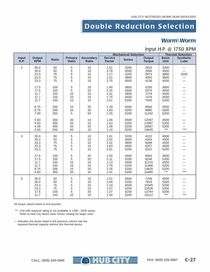
HUB CITY MOTORIZED WORM GEAR REDUCERS
C-27CALL: (605) 225-0360 FAX: (605) 225-0567
Mechanical Selection Thermal SelectionInput Output Ratio Primar y Secondar y Service Series Output Basic SyntheticH.P. RPM Ratio Ratio Factor Torque Unit Lube
2 35.0 50 5 10 1.51 3200 2815 3200 —35.0 50 5 10 3.78 4500 2895 4500 —23.3 75 5 15 1.17 3200 3974 3800 320023.3 75 5 15 1.51 3800 4060 3800 —23.3 75 5 15 2.75 4500 4138 4500 —
17.5 100 5 20 1.40 3800 5250 3800 —17.5 100 5 20 2.25 4500 5375 4500 —11.7 150 10 15 1.01 3800 7274 4500 —11.7 150 10 15 1.75 4500 7476 4500 —11.7 150 10 15 2.51 5200 7645 5200 —
8.75 200 10 20 1.29 4500 9566 4500 —8.75 200 10 20 1.83 5200 9880 5200 —7.00 250 5 50 1.25 5200 11342 5200 —
5.83 300 20 15 1.06 4500 12597 4500 —5.83 300 20 15 1.52 5200 12997 5200 —4.38 400 20 20 1.09 5200 16587 5200 —3.50 500 50 10 1.10 5200 16645 *** ***
3 35.0 50 5 10 1.01 3200 4222 4500 —35.0 50 5 10 2.52 4500 4343 4500 —23.3 75 5 15 1.01 3800 6089 4500 —23.3 75 5 15 1.83 4500 6207 4500 —23.3 75 5 15 2.61 5200 6322 5200 —
17.5 100 5 20 1.50 4500 8063 4500 —17.5 100 5 20 2.11 5200 8246 5200 —11.7 150 10 15 1.13 4500 11215 4500 —11.7 150 10 15 1.75 5200 11468 5200 —8.75 200 10 20 1.25 5200 14820 5200 —5.83 300 20 15 1.01 5200 19495 *** ***
5 35.0 50 5 10 1.51 4500 7238 4500 —35.0 50 5 10 2.04 5200 7819 5200 —23.3 75 5 15 1.10 4500 10345 5200 —23.3 75 5 15 1.57 5200 10536 5200 —17.5 100 5 20 1.27 5200 13744 5200 —11.7 150 10 15 1.00 5200 19114 *** ***
All torque values listed in inch-pounds.
*** Unit with required rating is not available in 1300 - 5200 series.Refer to Hub City Worm Gear Drives catalog for larger units.
— Indicates the series listed in the previous column has the required thermal capacity without this thermal device.
D o u b l e R e d u c t i o n S e l e c t i o n
Worm\Worm
Input H.P. @ 1750 RPM
HUB CITY MOTORIZED WORM GEAR REDUCERS
CALL: (605) 225-0360 FAX: (605) 225-0567C-28
D o u b l e R e d u c t i o n
OUTPUT SHAFT MODEL
HOLLOW BORE MODEL
Models13041804210426043204380445045204
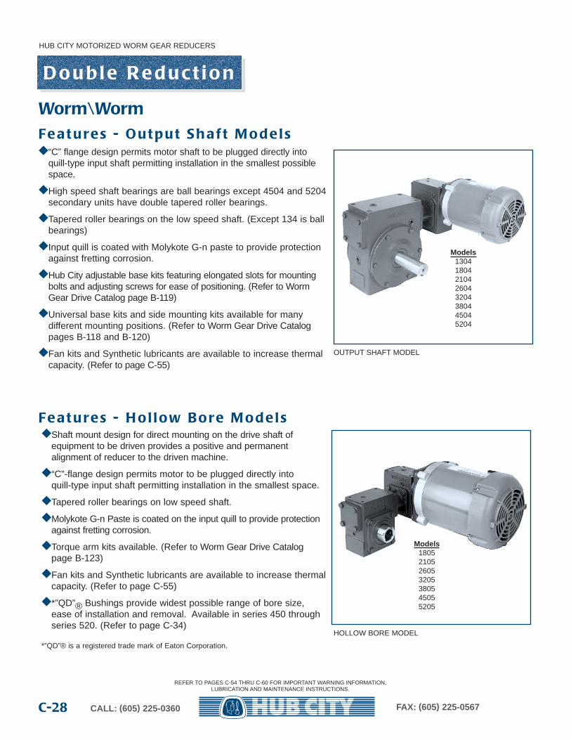
◆ Shaft mount design for direct mounting on the drive shaft ofequipment to be driven provides a positive and permanent alignment of reducer to the driven machine.
◆ “C”-flange design permits motor to be plugged directly intoquill-type input shaft permitting installation in the smallest space.
◆ Tapered roller bearings on low speed shaft.
◆ Molykote G-n Paste is coated on the input quill to provide protectionagainst fretting corrosion.
◆ Torque arm kits available. (Refer to Worm Gear Drive Catalog page B-123)
◆ Fan kits and Synthetic lubricants are available to increase thermalcapacity. (Refer to page C-55)
◆ *”QD”® Bushings provide widest possible range of bore size,ease of installation and removal. Available in series 450 throughseries 520. (Refer to page C-34)
*”QD”® is a registered trade mark of Eaton Corporation.
Models1805210526053205380545055205
Worm\WormFe a t u re s - O u t p u t S h a f t M o d e l s
Fe a t u re s - H o l l ow B o re M o d e l s
◆ “C” flange design permits motor shaft to be plugged directly intoquill-type input shaft permitting installation in the smallest possiblespace.
◆ High speed shaft bearings are ball bearings except 4504 and 5204secondary units have double tapered roller bearings.
◆ Tapered roller bearings on the low speed shaft. (Except 134 is ballbearings)
◆ Input quill is coated with Molykote G-n paste to provide protectionagainst fretting corrosion.
◆ Hub City adjustable base kits featuring elongated slots for mountingbolts and adjusting screws for ease of positioning. (Refer to WormGear Drive Catalog page B-119)
◆ Universal base kits and side mounting kits available for many different mounting positions. (Refer to Worm Gear Drive Catalogpages B-118 and B-120)
◆ Fan kits and Synthetic lubricants are available to increase thermalcapacity. (Refer to page C-55)
REFER TO PAGES C-54 THRU C-60 FOR IMPORTANT WARNING INFORMATION,LUBRICATION AND MAINTENANCE INSTRUCTIONS.
HUB CITY MOTORIZED WORM GEAR REDUCERS
C-29CALL: (605) 225-0360 FAX: (605) 225-0567
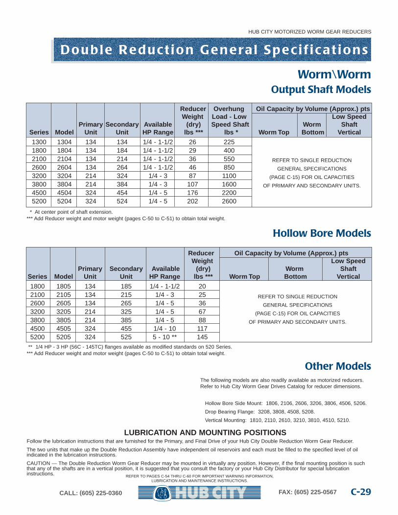
LUBRICATION AND MOUNTING POSITIONSFollow the lubrication instructions that are furnished for the Primary, and Final Drive of your Hub City Double Reduction Worm Gear Reducer.
The two units that make up the Double Reduction Assembly have independent oil reservoirs and each must be filled to the specified level of oilindicated in the lubrication instructions.
CAUTION — The Double Reduction Worm Gear Reducer may be mounted in virtually any position. However, if the final mounting position is suchthat any of the shafts are in a vertical position, it is suggested that you consult the factory or your Hub City Distributor for special lubricationinstructions.
Reducer Overhung Oil Capacity b y Volume (Appr ox.) ptsWeight Load - Lo w Low Speed
Primar y Secondar y Availab le (dry) Speed Shaft Worm ShaftSeries Model Unit Unit HP Range lbs *** lbs * Worm Top Bottom Vertical
1300 1304 134 134 1/4 - 1-1/2 26 2251800 1804 134 184 1/4 - 1-1/2 29 4002100 2104 134 214 1/4 - 1-1/2 36 5502600 2604 134 264 1/4 - 1-1/2 46 8503200 3204 214 324 1/4 - 3 87 11003800 3804 214 384 1/4 - 3 107 16004500 4504 324 454 1/4 - 5 176 22005200 5204 324 524 1/4 - 5 202 2600
* At center point of shaft extension.*** Add Reducer weight and motor weight (pages C-50 to C-51) to obtain total weight.
Output Shaft Models
Reducer Oil Capacity b y Volume (Appr ox.) ptsWeight Low Speed
Primar y Secondar y Availab le (dry) Worm ShaftSeries Model Unit Unit HP Range lbs *** Worm Top Bottom Vertical
1800 1805 134 185 1/4 - 1-1/2 202100 2105 134 215 1/4 - 3 252600 2605 134 265 1/4 - 5 363200 3205 214 325 1/4 - 5 673800 3805 214 385 1/4 - 5 884500 4505 324 455 1/4 - 10 1175200 5205 324 525 5 - 10 ** 145
** 1/4 HP - 3 HP (56C - 145TC) flanges available as modified standards on 520 Series.*** Add Reducer weight and motor weight (pages C-50 to C-51) to obtain total weight.
Hollow Bore Models
The following models are also readily available as motorized reducers.Refer to Hub City Worm Gear Drives Catalog for reducer dimensions.
Hollow Bore Side Mount: 1806, 2106, 2606, 3206, 3806, 4506, 5206.
Drop Bearing Flange: 3208, 3808, 4508, 5208.
Vertical Mounting: 1810, 2110, 2610, 3210, 3810, 4510, 5210.
Other Models
REFER TO SINGLE REDUCTION
GENERAL SPECIFICATIONS
(PAGE C-15) FOR OIL CAPACITIES
OF PRIMARY AND SECONDARY UNITS.
REFER TO SINGLE REDUCTION
GENERAL SPECIFICATIONS
(PAGE C-15) FOR OIL CAPACITIES
OF PRIMARY AND SECONDARY UNITS.
D o u b l e R e d u c t i o n G e n e ra l S p e c i f i c a t i o n s
Worm\Worm
REFER TO PAGES C-54 THRU C-60 FOR IMPORTANT WARNING INFORMATION,LUBRICATION AND MAINTENANCE INSTRUCTIONS.
HUB CITY MOTORIZED WORM GEAR REDUCERS
CALL: (605) 225-0360 FAX: (605) 225-0567C-30
D o u b l e R e d u c t i o n O u t p u t S h a f t M o d e l s
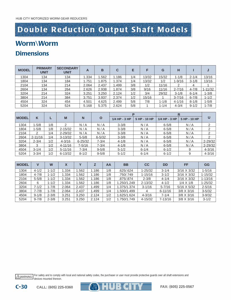
MODEL PRIMARY SECONDARY A B C E F G H I JUNIT UNIT
1304 134 134 1.334 1.562 1.186 1/4 13/32 15/32 1-1/8 2-1/4 13/161804 134 184 1.751 1.875 1.374 1/4 13/32 1/2 1-9/16 3-1/8 13/162104 134 214 2.064 2.437 1.499 3/8 1/2 11/16 2 4 12604 134 264 2.626 2.938 1.874 3/8 9/16 11/16 2-7/16 4-7/8 1-11/323204 214 324 3.251 3.250 2.124 1/2 3/4 29/32 3-1/8 6-1/4 1-3/83804 214 384 3.751 3.937 2.374 1/2 15/16 1 3-7/16 6-7/8 1-1/24504 324 454 4.501 4.625 2.499 5/8 7/8 1-1/8 4-1/16 8-1/8 1-5/85204 324 524 5.168 5.375 2.624 5/8 1 1-1/4 4-3/4 9-1/2 1-7/8
P RUMODEL K L M N O 1/4 HP - 3 HP 5 HP - 10 HP 1/4 HP - 3 HP 5 HP - 10 HP
1304 1-5/8 1/8 2 N / A N / A 3-3/8 N / A 6-5/8 N / A 21804 1-5/8 1/8 2-15/32 N / A N / A 3-3/8 N / A 6-5/8 N / A 22104 2 1/4 2-29/32 N / A N / A 3-3/8 N / A 6-5/8 N / A 22604 2-11/16 1/4 3-13/32 5-5/8 6-5/32 3-3/8 N / A 6-5/8 N / A 23204 2-3/4 1/2 4-3/16 6-25/32 7-3/4 4-1/8 N / A 6-5/8 N / A 2-29/323804 3 1/2 4-11/16 7-5/16 7-3/4 4-1/8 N / A 6-5/8 N / A 2-29/324504 3-1/4 1/2 5-11/16 7-3/4 9-5/8 5-1/2 6-1/4 6-1/2 9 4-3/165204 3-3/4 1/2 6-13/32 8-1/2 9-5/8 5-1/2 6-1/4 6-1/2 9 4-3/16
MODEL V W X Y Z AA BB CC DD FF GG
1304 4-1/2 1-1/2 1.334 1.562 1.186 1/8 .625/.624 1-25/32 3-1/4 3/16 X 3/32 1-5/161804 4-7/8 1-1/2 1.334 1.562 1.186 1/8 .750/.749 1-15/16 3-1/2 3/16 X 3/32 1-15/322104 5-5/8 1-1/2 1.334 1.562 1.186 1/8 .875/.874 2-3/8 4-1/4 3/16 X 3/32 1-13/162604 6 1-1/2 1.334 1.562 1.186 1/8 1.250/1.249 2-13/32 4-1/2 1/4 X 1/8 1-25/323204 7-1/2 1-7/8 2.064 2.437 1.499 1/4 1.375/1.374 3-1/16 5-7/16 5/16 X 5/32 2-5/163804 7-7/8 1-7/8 2.064 2.437 1.499 1/4 1.500/1.499 4 6-11/16 3/8 X 3/16 3-5/324504 9-1/8 2-3/8 3.251 3.250 2.124 1/2 1.625/1.624 4-3/16 7-1/4 3/8 X 3/16 3-9/325204 9-7/8 2-3/8 3.251 3.250 2.124 1/2 1.750/1.749 4-15/32 7-13/16 3/8 X 3/16 3-1/2
Dimensions
WARNING: For safety and to comply with local and national safety codes, the purchaser or user must provide protective guards over all shaft extensions anddevices mounted thereon.
!
Worm\Worm
RA NOTAVAILABLE
LB
STYLE UR-LR
RBLAUL UR L LR RNOTAVAILABLE
HUB CITY MOTORIZED WORM GEAR REDUCERS
C-31CALL: (605) 225-0360 FAX: (605) 225-0567
M V W
P U
DD DD
Z
X C.D.
Y
BB
E NC(4) F DEEP TOP(4) G DEEP BOTTOM
CC
I
K
L NPT (5)
C
A C.D.
B
FF KEYWAYGG EFF. LGTH.
TYP. BOTH EXTENSIONS
H
J
S
T
N
O
OPTIONAL FAN
AA NPT (5)
LQ
CC
R
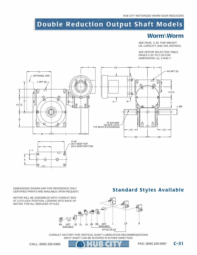
D o u b l e R e d u c t i o n O u t p u t S h a f t M o d e l s
DIMENSIONS SHOWN ARE FOR REFERENCE ONLY.CERTIFIED PRINTS ARE AVAILABLE UPON REQUEST. S t a n d a rd S t y l e s Ava i l a b l e
CONSULT FACTORY FOR VERTICAL SHAFT LUBRICATION RECOMMENDATIONSINPUT SHAFT CAN BE ROTATED IN EITHER DIRECTION
SEE PAGE C-29 FOR WEIGHT,OIL CAPACITY, AND OHL RATINGS.
SEE MOTOR SELECTION TABLEPAGES C-52 TO C-53 FORDIMENSIONS LQ, S AND T.
Worm\Worm
MOTOR WILL BE ASSEMBLED WITH CONDUIT BOXAT 3 O’CLOCK POSITION, LOOKING INTO BACK OFMOTOR, FOR ALL REDUCER STYLES
HUB CITY MOTORIZED WORM GEAR REDUCERS
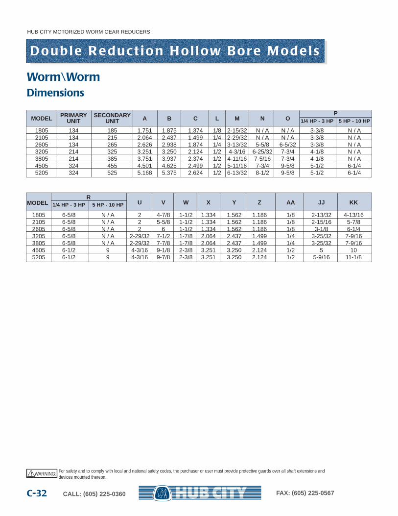
CALL: (605) 225-0360 FAX: (605) 225-0567C-32
D o u b l e R e d u c t i o n H o l l ow B o re M o d e l s
RU V W X Y Z AA JJ KKMODEL 1/4 HP - 3 HP 5 HP - 10 HP
1805 6-5/8 N / A 2 4-7/8 1-1/2 1.334 1.562 1.186 1/8 2-13/32 4-13/162105 6-5/8 N / A 2 5-5/8 1-1/2 1.334 1.562 1.186 1/8 2-15/16 5-7/82605 6-5/8 N / A 2 6 1-1/2 1.334 1.562 1.186 1/8 3-1/8 6-1/43205 6-5/8 N / A 2-29/32 7-1/2 1-7/8 2.064 2.437 1.499 1/4 3-25/32 7-9/163805 6-5/8 N / A 2-29/32 7-7/8 1-7/8 2.064 2.437 1.499 1/4 3-25/32 7-9/164505 6-1/2 9 4-3/16 9-1/8 2-3/8 3.251 3.250 2.124 1/2 5 105205 6-1/2 9 4-3/16 9-7/8 2-3/8 3.251 3.250 2.124 1/2 5-9/16 11-1/8
MODEL PRIMARY SECONDARY A B C L M N OP
UNIT UNIT 1/4 HP - 3 HP 5 HP - 10 HP
1805 134 185 1.751 1.875 1.374 1/8 2-15/32 N / A N / A 3-3/8 N / A2105 134 215 2.064 2.437 1.499 1/4 2-29/32 N / A N / A 3-3/8 N / A2605 134 265 2.626 2.938 1.874 1/4 3-13/32 5-5/8 6-5/32 3-3/8 N / A3205 214 325 3.251 3.250 2.124 1/2 4-3/16 6-25/32 7-3/4 4-1/8 N / A3805 214 385 3.751 3.937 2.374 1/2 4-11/16 7-5/16 7-3/4 4-1/8 N / A4505 324 455 4.501 4.625 2.499 1/2 5-11/16 7-3/4 9-5/8 5-1/2 6-1/45205 324 525 5.168 5.375 2.624 1/2 6-13/32 8-1/2 9-5/8 5-1/2 6-1/4
Dimensions
WARNING: For safety and to comply with local and national safety codes, the purchaser or user must provide protective guards over all shaft extensions anddevices mounted thereon.
!
Worm\Worm
LBNOTAVAILABLE
RA RBLAUL UR NOTAVAILABLE
STYLE UR
ONLY ONE SECONDARY STYLE AVAILABLE. ORDER BY PRIMARY STYLE ONLY.
HUB CITY MOTORIZED WORM GEAR REDUCERS
C-33CALL: (605) 225-0360 FAX: (605) 225-0567
JJ
KK
HH BORE
II KEYWAY
M V W
P U
Z
X C.D.
Y
L NPT (5)
C
A C.D.
B
S
T
N
O
OPTIONAL FAN
AA NPT (5)
LQ
LL SOCKET S.S.
R
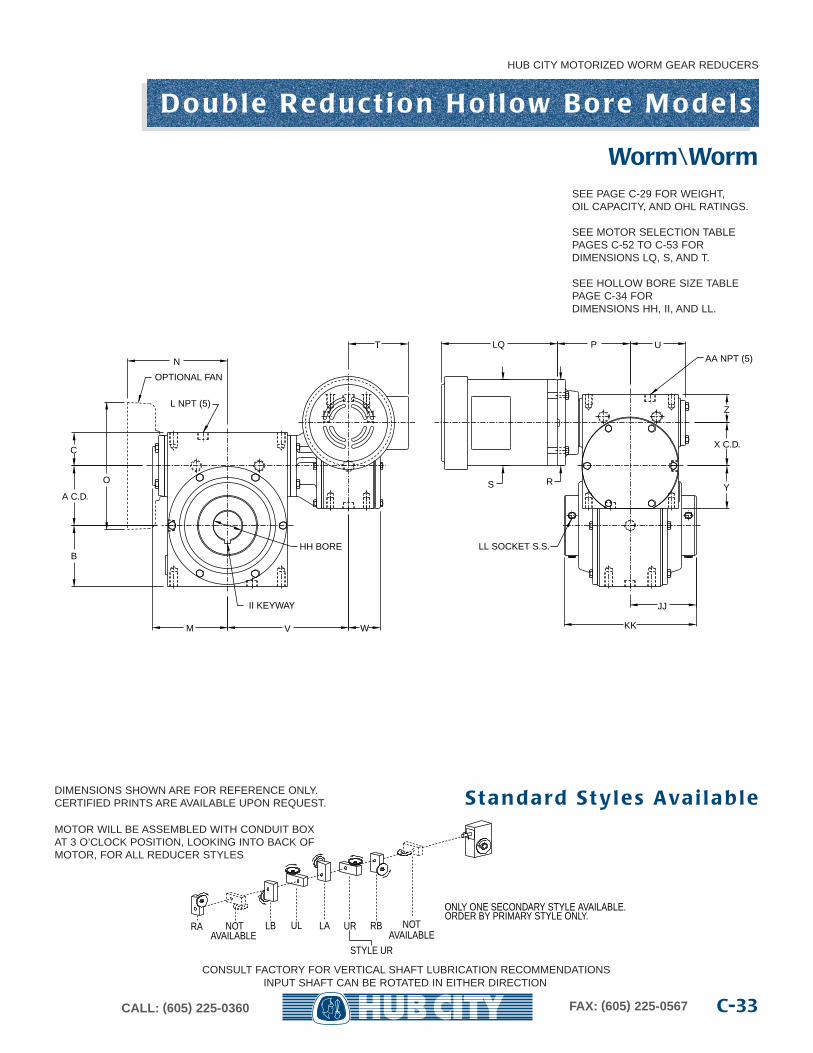
D o u b l e R e d u c t i o n H o l l ow B o re M o d e l s
DIMENSIONS SHOWN ARE FOR REFERENCE ONLY.CERTIFIED PRINTS ARE AVAILABLE UPON REQUEST. S t a n d a rd S t y l e s Ava i l a b l e
CONSULT FACTORY FOR VERTICAL SHAFT LUBRICATION RECOMMENDATIONSINPUT SHAFT CAN BE ROTATED IN EITHER DIRECTION
SEE PAGE C-29 FOR WEIGHT,OIL CAPACITY, AND OHL RATINGS.
SEE MOTOR SELECTION TABLEPAGES C-52 TO C-53 FOR DIMENSIONS LQ, S, AND T.
SEE HOLLOW BORE SIZE TABLEPAGE C-34 FOR DIMENSIONS HH, II, AND LL.
Worm\Worm
MOTOR WILL BE ASSEMBLED WITH CONDUIT BOXAT 3 O’CLOCK POSITION, LOOKING INTO BACK OFMOTOR, FOR ALL REDUCER STYLES

HUB CITY MOTORIZED WORM GEAR REDUCERS
CALL: (605) 225-0360 FAX: (605) 225-0567C-34
D o u b l e R e d u c t i o n B o re C h a r t s
MODELBORE KEYWAY KEY FURNISHED SETSCREWS FURNISHED
HH II LL
1805 15/16 1/4 X 1/8 1/4 Sq. 1/4 N.C. X 1/4 LG.1 (MAX.) 1/4 X 1/8 1/4 Sq. 1/4 N.C. X 1/4 LG.
2105 15/16 1/4 X 1/8 1/4 Sq. 5/16 N.C. X 5/16 LG.1 1/4 X 1/8 1/4 Sq. 5/16 N.C. X 5/16 LG.
1-3/16 (MAX.) 1/4 X 1/8 1/4 Sq. 5/16 N.C. X 5/16 LG.
2605 1 1/4 X 1/8 1/4 Sq. 5/16 N.C. X 5/16 LG. QTY (4)1-3/16 1/4 X 1/8 1/4 Sq. 5/16 N.C. X 5/16 LG. QTY (4)1-1/4 1/4 X 1/8 1/4 Sq. 5/16 N.C. X 5/16 LG. QTY (4)
1-7/16 (MAX.) 3/8 X 1/8 3/8 X 5/16 5/16 N.C. X 5/16 LG. QTY (2) 1/4 N.C. X 1/4 LG. QTY (2)
3205 1-7/16 3/8 X 3/16 3/8 Sq. 3/8 N.C. X 5/8 LG.AND 1-15/16 1/2 X 1/4 1/2 Sq. 3/8 N.C. X 3/8 LG.3805 2 1/2 X 1/4 1/2 Sq. 3/8 N.C. X 3/8 LG.
2-3/16 (MAX.) 1/2 X 1/8 1/2 X 3/8 3/8 N.C. X 3/8 LG.
QD BUSHINGMODEL TYPE S.F. BUSHING KEY* KIT NUMBER
BORE SIZE KEYWAYHH DIA. II
4505 1-15/16 1/2 X 1/4 1/2 X 1/2 0229-026832 1/2 X 1/4 1/2 X 1/2 0229-02684
2-3/16 1/2 X 1/4 1/2 X 1/2 0229-026852-7/16 5/8 X 3/16 5/8 X 1/2 0229-02686
2-15/16 3/4 X 1/32 3/4 X 13/32 0229-02687
QD BUSHINGMODEL TYPE E BUSHING KEY* KIT NUMBER
BORE SIZE KEYWAYHH DIA. II
5205 2-3/16 1/2 X 1/4 1/2 X 1/2 0229-026882-7/16 5/8 X 5/16 5/8 X 5/8 0229-02689
2-15/16 3/4 X 1/8 3/4 X 1/2 0229-026903 3/4 X 1/8 3/4 X 1/2 0229-02691
3-3/16 3/4 X 1/8 3/4 X 1/2 0229-026923-7/16 7/8 X 1/16 7/8 X 1/2 0229-02693
MODEL 1805 THRU 3805 BORE TOLERANCE NOMINAL +.002
* Kit includes two Bushings with Keyways and one Key.
NOTE: Order by QD Bushing Kit Number. Bushing Kits are not included in reducer price.
WARNING: For safety and to comply with local and national safety codes, the purchaser or user must provide protective guards over all shaft extensions anddevices mounted thereon.
!
Worm\Worm
N o t e s
HUB CITY MOTORIZED WORM GEAR REDUCERS
C-35CALL: (605) 225-0360 FAX: (605) 225-0567
HUB CITY MOTORIZED WORM GEAR REDUCERS
CALL: (605) 225-0360 FAX: (605) 225-0567C-36
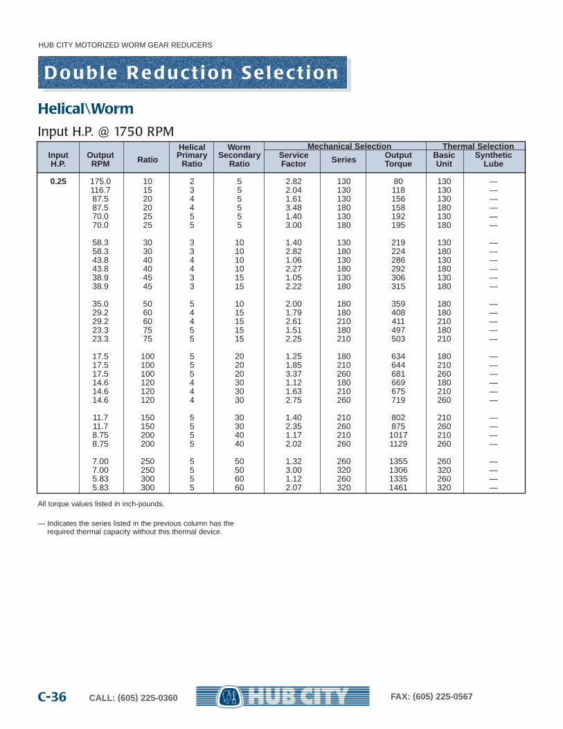
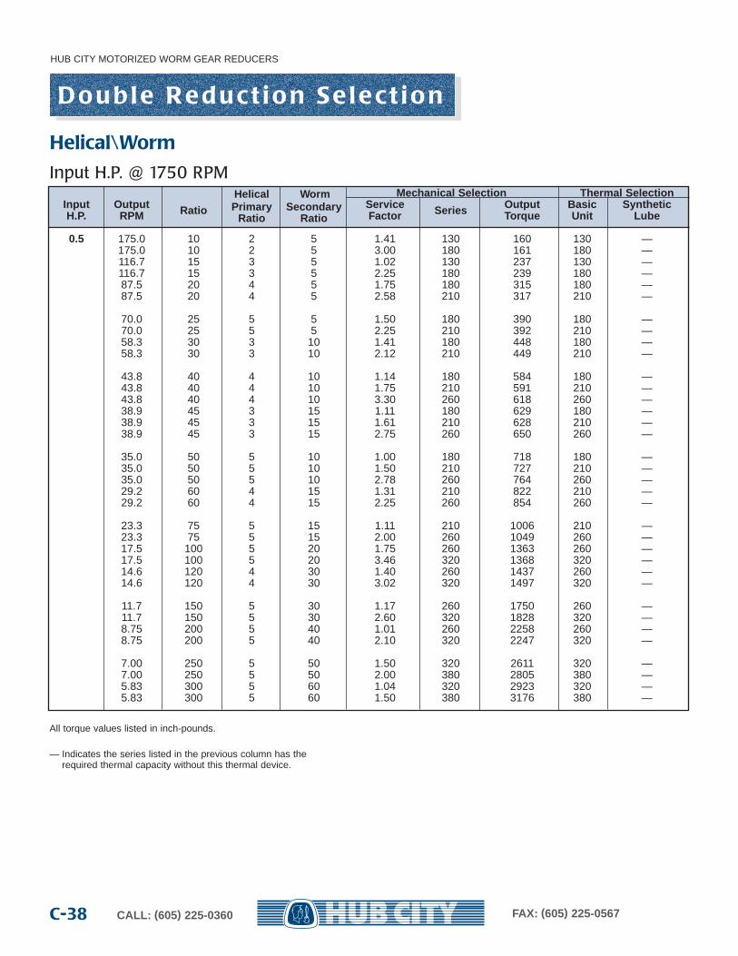
All torque values listed in inch-pounds.
— Indicates the series listed in the previous column has the required thermal capacity without this thermal device.
Helical Worm Mechanical Selection Thermal SelectionInput Output Ratio Primar y Secondar y Service Series Output Basic SyntheticH.P. RPM Ratio Ratio Factor Torque Unit Lube
0.25 175.0 10 2 5 2.82 130 80 130 —116.7 15 3 5 2.04 130 118 130 —87.5 20 4 5 1.61 130 156 130 —87.5 20 4 5 3.48 180 158 180 —70.0 25 5 5 1.40 130 192 130 —70.0 25 5 5 3.00 180 195 180 —
58.3 30 3 10 1.40 130 219 130 —58.3 30 3 10 2.82 180 224 180 —43.8 40 4 10 1.06 130 286 130 —43.8 40 4 10 2.27 180 292 180 —38.9 45 3 15 1.05 130 306 130 —38.9 45 3 15 2.22 180 315 180 —
35.0 50 5 10 2.00 180 359 180 —29.2 60 4 15 1.79 180 408 180 —29.2 60 4 15 2.61 210 411 210 —23.3 75 5 15 1.51 180 497 180 —23.3 75 5 15 2.25 210 503 210 —
17.5 100 5 20 1.25 180 634 180 —17.5 100 5 20 1.85 210 644 210 —17.5 100 5 20 3.37 260 681 260 —14.6 120 4 30 1.12 180 669 180 —14.6 120 4 30 1.63 210 675 210 —14.6 120 4 30 2.75 260 719 260 —
11.7 150 5 30 1.40 210 802 210 —11.7 150 5 30 2.35 260 875 260 —8.75 200 5 40 1.17 210 1017 210 —8.75 200 5 40 2.02 260 1129 260 —
7.00 250 5 50 1.32 260 1355 260 —7.00 250 5 50 3.00 320 1306 320 —5.83 300 5 60 1.12 260 1335 260 —5.83 300 5 60 2.07 320 1461 320 —
D o u b l e R e d u c t i o n S e l e c t i o n
Helical\Worm
Input H.P. @ 1750 RPM

HUB CITY MOTORIZED WORM GEAR REDUCERS
C-37CALL: (605) 225-0360 FAX: (605) 225-0567
All torque values listed in inch-pounds.
— Indicates the series listed in the previous column has the required thermal capacity without this thermal device.
Helical Worm Mechanical Selection Thermal SelectionInput Output Ratio Primar y Secondar y Service Series Output Basic SyntheticH.P. RPM Ratio Ratio Factor Torque Unit Lube
0.333 175.0 10 2 5 2.12 130 107 130 —116.7 15 3 5 1.53 130 158 130 —116.7 15 3 5 3.24 180 159 180 —87.5 20 4 5 1.25 130 207 130 —87.5 20 4 5 2.61 180 210 180 —
70.0 25 5 5 1.01 130 255 130 —70.0 25 5 5 2.25 180 259 180 —58.3 30 3 10 1.00 130 292 130 —58.3 30 3 10 2.12 180 298 180 —43.8 40 4 10 1.75 180 389 180 —43.8 40 4 10 2.57 210 393 210 —
38.9 45 3 15 1.66 180 419 180 —38.9 45 3 15 2.50 210 418 210 —35.0 50 5 10 1.50 180 478 180 —35.0 50 5 10 2.25 210 484 210 —29.2 60 4 15 1.40 180 544 180 —29.2 60 4 15 2.00 210 548 210 —
23.3 75 5 15 1.13 180 662 180 —23.3 75 5 15 1.66 210 670 210 —23.3 75 5 15 3.00 260 699 260 —17.5 100 5 20 1.40 210 858 210 —17.5 100 5 20 2.53 260 908 260 —
14.6 120 4 30 1.25 210 899 210 —14.6 120 4 30 2.05 260 957 260 —11.7 150 5 30 1.05 210 1069 210 —11.7 150 5 30 1.76 260 1166 260 —11.7 150 5 30 3.90 320 1218 320 —
8.75 200 5 40 1.52 260 1504 260 —8.75 200 5 40 3.15 320 1497 320 —7.00 250 5 50 1.00 260 1805 260 —7.00 250 5 50 2.25 320 1739 320 —5.83 300 5 60 1.56 320 1947 320 —5.83 300 5 60 2.25 380 2116 380 —
D o u b l e R e d u c t i o n S e l e c t i o n
Helical\Worm
Input H.P. @ 1750 RPM
HUB CITY MOTORIZED WORM GEAR REDUCERS
CALL: (605) 225-0360 FAX: (605) 225-0567C-38
All torque values listed in inch-pounds.
— Indicates the series listed in the previous column has the required thermal capacity without this thermal device.
Helical Worm Mechanical Selection Thermal SelectionInput Output Ratio Primar y Secondar y Service Series Output Basic SyntheticH.P. RPM Ratio Ratio Factor Torque Unit Lube
0.5 175.0 10 2 5 1.41 130 160 130 —175.0 10 2 5 3.00 180 161 180 —116.7 15 3 5 1.02 130 237 130 —116.7 15 3 5 2.25 180 239 180 —87.5 20 4 5 1.75 180 315 180 —87.5 20 4 5 2.58 210 317 210 —
70.0 25 5 5 1.50 180 390 180 —70.0 25 5 5 2.25 210 392 210 —58.3 30 3 10 1.41 180 448 180 —58.3 30 3 10 2.12 210 449 210 —
43.8 40 4 10 1.14 180 584 180 —43.8 40 4 10 1.75 210 591 210 —43.8 40 4 10 3.30 260 618 260 —38.9 45 3 15 1.11 180 629 180 —38.9 45 3 15 1.61 210 628 210 —38.9 45 3 15 2.75 260 650 260 —
35.0 50 5 10 1.00 180 718 180 —35.0 50 5 10 1.50 210 727 210 —35.0 50 5 10 2.78 260 764 260 —29.2 60 4 15 1.31 210 822 210 —29.2 60 4 15 2.25 260 854 260 —
23.3 75 5 15 1.11 210 1006 210 —23.3 75 5 15 2.00 260 1049 260 —17.5 100 5 20 1.75 260 1363 260 —17.5 100 5 20 3.46 320 1368 320 —14.6 120 4 30 1.40 260 1437 260 —14.6 120 4 30 3.02 320 1497 320 —
11.7 150 5 30 1.17 260 1750 260 —11.7 150 5 30 2.60 320 1828 320 —8.75 200 5 40 1.01 260 2258 260 —8.75 200 5 40 2.10 320 2247 320 —
7.00 250 5 50 1.50 320 2611 320 —7.00 250 5 50 2.00 380 2805 380 —5.83 300 5 60 1.04 320 2923 320 —5.83 300 5 60 1.50 380 3176 380 —
D o u b l e R e d u c t i o n S e l e c t i o n
Helical\Worm
Input H.P. @ 1750 RPM
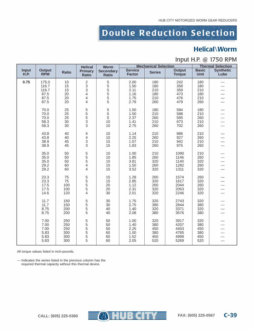
HUB CITY MOTORIZED WORM GEAR REDUCERS
C-39CALL: (605) 225-0360 FAX: (605) 225-0567
All torque values listed in inch-pounds.
— Indicates the series listed in the previous column has the required thermal capacity without this thermal device.
Helical Worm Mechanical Selection Thermal SelectionInput Output Ratio Primar y Secondar y Service Series Output Basic SyntheticH.P. RPM Ratio Ratio Factor Torque Unit Lube
0.75 175.0 10 2 5 2.00 180 242 180 —116.7 15 3 5 1.50 180 358 180 —116.7 15 3 5 2.11 210 359 210 —87.5 20 4 5 1.16 180 473 180 —87.5 20 4 5 1.75 210 476 210 —87.5 20 4 5 2.79 260 479 260 —
70.0 25 5 5 1.00 180 584 180 —70.0 25 5 5 1.50 210 588 210 —70.0 25 5 5 2.37 260 595 260 —58.3 30 3 10 1.41 210 673 210 —58.3 30 3 10 2.75 260 702 260 —
43.8 40 4 10 1.14 210 886 210 —43.8 40 4 10 2.25 260 927 260 —38.9 45 3 15 1.07 210 942 210 —38.9 45 3 15 1.83 260 975 260 —
35.0 50 5 10 1.00 210 1090 210 —35.0 50 5 10 1.85 260 1146 260 —35.0 50 5 10 3.81 320 1140 320 —29.2 60 4 15 1.50 260 1282 260 —29.2 60 4 15 3.52 320 1311 320 —
23.3 75 5 15 1.28 260 1574 260 —23.3 75 5 15 2.85 320 1617 320 —17.5 100 5 20 1.12 260 2044 260 —17.5 100 5 20 2.31 320 2053 320 —14.6 120 4 30 2.01 320 2246 320 —
11.7 150 5 30 1.75 320 2743 320 —11.7 150 5 30 2.75 380 2844 380 —8.75 200 5 40 1.40 320 3371 320 —8.75 200 5 40 2.08 380 3576 380 —
7.00 250 5 50 1.00 320 3917 320 —7.00 250 5 50 1.40 380 4207 380 —7.00 250 5 50 2.25 450 4403 450 —5.83 300 5 60 1.00 380 4765 380 —5.83 300 5 60 1.52 450 4999 450 —5.83 300 5 60 2.05 520 5269 520 —
D o u b l e R e d u c t i o n S e l e c t i o n
Helical\Worm
Input H.P. @ 1750 RPM

HUB CITY MOTORIZED WORM GEAR REDUCERS
CALL: (605) 225-0360 FAX: (605) 225-0567C-40
All torque values listed in inch-pounds.
— Indicates the series listed in the previous column has the required thermal capacity without this thermal device.
Helical Worm Mechanical Selection Thermal SelectionInput Output Ratio Primar y Secondar y Service Series Output Basic SyntheticH.P. RPM Ratio Ratio Factor Torque Unit Lube
1 175.0 10 2 5 1.50 180 323 180 —175.0 10 2 5 2.09 210 322 210 —116.7 15 3 5 1.08 180 478 180 —116.7 15 3 5 1.58 210 478 210 —116.7 15 3 5 2.54 260 482 260 —
87.5 20 4 5 1.29 210 634 210 —87.5 20 4 5 2.09 260 639 260 —70.0 25 5 5 1.08 210 784 210 —70.0 25 5 5 1.78 260 793 260 —70.0 25 5 5 4.50 320 807 320 —
58.3 30 3 10 1.06 210 897 210 —58.3 30 3 10 2.05 260 497 260 —43.8 40 4 10 1.65 260 1236 260 —43.8 40 4 10 3.36 320 1229 320 —38.9 45 3 15 1.40 260 1300 260 —38.9 45 3 15 3.04 320 1324 320 —
35.0 50 5 10 1.40 260 1527 260 —35.0 50 5 10 3.00 320 1520 320 —29.2 60 4 15 1.12 260 1709 260 —29.2 60 4 15 2.75 320 1748 320 —23.3 75 5 15 1.00 260 2098 260 —23.3 75 5 15 2.14 320 2156 320 —
17.5 100 5 20 1.75 320 2737 320 —17.5 100 5 20 2.59 380 2841 380 —14.6 120 4 30 1.51 320 2995 320 —14.6 120 4 30 2.33 380 3090 380 —
11.7 150 5 30 1.30 320 3657 320 —11.7 150 5 30 2.00 380 3793 380 —8.75 200 5 40 1.05 320 4494 380 3208.75 200 5 40 1.56 380 4768 380 —8.75 200 5 40 2.50 450 4950 450 —
7.00 250 5 50 1.00 380 5609 380 —7.00 250 5 50 1.63 450 5871 450 —7.00 250 5 50 2.25 520 6122 520 —5.83 300 5 60 1.14 450 6666 450 —5.83 300 5 60 1.54 520 7026 520 —
D o u b l e R e d u c t i o n S e l e c t i o n
Helical\Worm
Input H.P. @ 1750 RPM
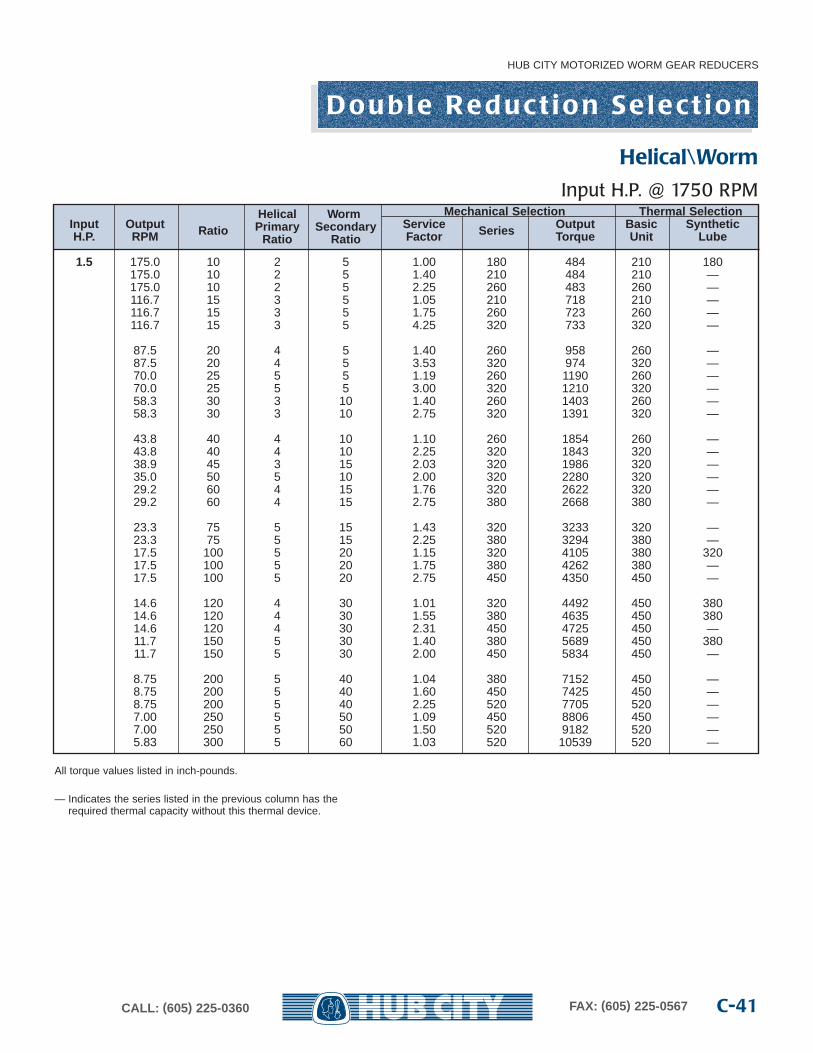
HUB CITY MOTORIZED WORM GEAR REDUCERS
C-41CALL: (605) 225-0360 FAX: (605) 225-0567
All torque values listed in inch-pounds.
— Indicates the series listed in the previous column has the required thermal capacity without this thermal device.
Helical Worm Mechanical Selection Thermal SelectionInput Output Ratio Primar y Secondar y Service Series Output Basic SyntheticH.P. RPM Ratio Ratio Factor Torque Unit Lube
1.5 175.0 10 2 5 1.00 180 484 210 180175.0 10 2 5 1.40 210 484 210 —175.0 10 2 5 2.25 260 483 260 —116.7 15 3 5 1.05 210 718 210 —116.7 15 3 5 1.75 260 723 260 —116.7 15 3 5 4.25 320 733 320 —
87.5 20 4 5 1.40 260 958 260 —87.5 20 4 5 3.53 320 974 320 —70.0 25 5 5 1.19 260 1190 260 —70.0 25 5 5 3.00 320 1210 320 —58.3 30 3 10 1.40 260 1403 260 —58.3 30 3 10 2.75 320 1391 320 —
43.8 40 4 10 1.10 260 1854 260 —43.8 40 4 10 2.25 320 1843 320 —38.9 45 3 15 2.03 320 1986 320 —35.0 50 5 10 2.00 320 2280 320 —29.2 60 4 15 1.76 320 2622 320 —29.2 60 4 15 2.75 380 2668 380 —
23.3 75 5 15 1.43 320 3233 320 —23.3 75 5 15 2.25 380 3294 380 —17.5 100 5 20 1.15 320 4105 380 32017.5 100 5 20 1.75 380 4262 380 —17.5 100 5 20 2.75 450 4350 450 —
14.6 120 4 30 1.01 320 4492 450 38014.6 120 4 30 1.55 380 4635 450 38014.6 120 4 30 2.31 450 4725 450 —11.7 150 5 30 1.40 380 5689 450 38011.7 150 5 30 2.00 450 5834 450 —
8.75 200 5 40 1.04 380 7152 450 —8.75 200 5 40 1.60 450 7425 450 —8.75 200 5 40 2.25 520 7705 520 —7.00 250 5 50 1.09 450 8806 450 —7.00 250 5 50 1.50 520 9182 520 —5.83 300 5 60 1.03 520 10539 520 —
D o u b l e R e d u c t i o n S e l e c t i o n
Helical\Worm
Input H.P. @ 1750 RPM
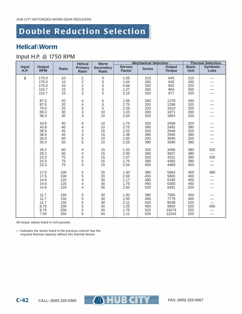
HUB CITY MOTORIZED WORM GEAR REDUCERS
CALL: (605) 225-0360 FAX: (605) 225-0567C-42
All torque values listed in inch-pounds.
— Indicates the series listed in the previous column has the required thermal capacity without this thermal device.
Helical Worm Mechanical Selection Thermal SelectionInput Output Ratio Primar y Secondar y Service Series Output Basic SyntheticH.P. RPM Ratio Ratio Factor Torque Unit Lube
2 175.0 10 2 5 1.05 210 645 210 —175.0 10 2 5 1.64 260 645 260 —175.0 10 2 5 4.06 320 652 320 —116.7 15 3 5 1.27 260 964 260 —116.7 15 3 5 3.19 320 977 320 —
87.5 20 4 5 1.05 260 1278 260 —87.5 20 4 5 2.75 320 1298 320 —70.0 25 5 5 2.25 320 1613 320 —58.3 30 3 10 1.03 260 1871 260 —58.3 30 3 10 2.04 320 1854 320 —
43.8 40 4 10 1.75 320 2458 320 —43.8 40 4 10 2.75 380 2492 380 —38.9 45 3 15 1.52 320 2648 320 —38.9 45 3 15 2.38 380 2690 380 —35.0 50 5 10 1.50 320 3040 320 —35.0 50 5 10 2.25 380 3090 380 —
29.2 60 4 15 1.32 320 3496 380 32029.2 60 4 15 2.00 380 3557 380 —23.3 75 5 15 1.07 320 4311 380 32023.3 75 5 15 1.75 380 4392 380 —23.3 75 5 15 2.54 450 4469 450 —
17.5 100 5 20 1.30 380 5683 450 38017.5 100 5 20 2.06 450 5800 450 —14.6 120 4 30 1.17 380 6180 450 —14.6 120 4 30 1.75 450 6300 450 —14.6 120 4 30 2.50 520 6491 520 —
11.7 150 5 30 1.00 380 7585 450 —11.7 150 5 30 1.50 450 7779 450 —11.7 150 5 30 2.11 520 8038 520 —8.75 200 5 40 1.25 450 9900 520 4508.75 200 5 40 1.75 520 10274 520 —7.00 250 5 50 1.11 520 12243 520 —
D o u b l e R e d u c t i o n S e l e c t i o n
Helical\Worm
Input H.P. @ 1750 RPM
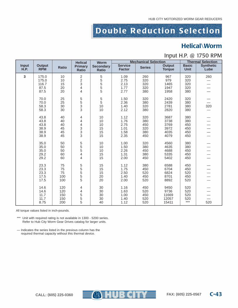
HUB CITY MOTORIZED WORM GEAR REDUCERS
C-43CALL: (605) 225-0360 FAX: (605) 225-0567
Helical Worm Mechanical Selection Thermal SelectionInput Output Ratio Primar y Secondar y Service Series Output Basic SyntheticH.P. RPM Ratio Ratio Factor Torque Unit Lube
3 175.0 10 2 5 1.09 260 967 320 260175.0 10 2 5 2.75 320 979 320 —116.7 15 3 5 2.13 320 1465 320 —87.5 20 4 5 1.77 320 1947 320 —87.5 20 4 5 2.77 380 1958 380 —
70.0 25 5 5 1.50 320 2420 320 —70.0 25 5 5 2.36 380 2439 380 —58.3 30 3 10 1.40 320 2781 380 32058.3 30 3 10 2.12 380 2820 380 —
43.8 40 4 10 1.12 320 3687 380 —43.8 40 4 10 1.76 380 3738 380 —43.8 40 4 10 2.75 450 3769 450 —38.9 45 3 15 1.01 320 3972 450 —38.9 45 3 15 1.58 380 4035 450 —38.9 45 3 15 2.35 450 4079 450 —
35.0 50 5 10 1.00 320 4560 380 —35.0 50 5 10 1.50 380 4635 380 —35.0 50 5 10 2.26 450 4688 450 —29.2 60 4 15 1.31 380 5335 450 —29.2 60 4 15 2.00 450 5402 450 —
23.3 75 5 15 1.12 380 6588 450 —23.3 75 5 15 1.75 450 6704 450 —23.3 75 5 15 2.50 520 6824 520 —17.5 100 5 20 1.40 450 8701 450 —17.5 100 5 20 2.00 520 8892 520 —
14.6 120 4 30 1.16 450 9450 520 —14.6 120 4 30 1.63 520 9736 520 —11.7 150 5 30 1.00 450 11669 520 —11.7 150 5 30 1.40 520 12057 520 —8.75 200 5 40 1.12 520 15411 *** 520
D o u b l e R e d u c t i o n S e l e c t i o n
Helical\Worm
Input H.P. @ 1750 RPM
All torque values listed in inch-pounds.
*** Unit with required rating is not available in 1300 - 5200 series.Refer to Hub City Worm Gear Drives catalog for larger units.
— Indicates the series listed in the previous column has the required thermal capacity without this thermal device.
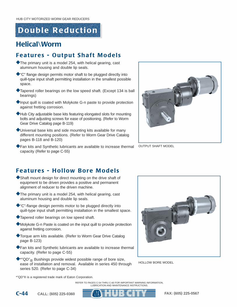
HUB CITY MOTORIZED WORM GEAR REDUCERS
CALL: (605) 225-0360 FAX: (605) 225-0567C-44
OUTPUT SHAFT MODEL
HOLLOW BORE MODEL
Helical\Worm
◆ Shaft mount design for direct mounting on the drive shaft ofequipment to be driven provides a positive and permanent alignment of reducer to the driven machine.
◆ The primary unit is a model 254, with helical gearing, cast aluminum housing and double lip seals.
◆ “C”-flange design permits motor to be plugged directly intoquill-type input shaft permitting installation in the smallest space.
◆ Tapered roller bearings on low speed shaft.
◆ Molykote G-n Paste is coated on the input quill to provide protectionagainst fretting corrosion.
◆ Torque arm kits available. (Refer to Worm Gear Drive Catalog page B-123)
◆ Fan kits and Synthetic lubricants are available to increase thermalcapacity. (Refer to page C-55)
◆ *”QD”® Bushings provide widest possible range of bore size,ease of installation and removal. Available in series 450 throughseries 520. (Refer to page C-34)
*”QD”® is a registered trade mark of Eaton Corporation.
◆ The primary unit is a model 254, with helical gearing, cast aluminum housing and double lip seals.
◆ “C” flange design permits motor shaft to be plugged directly intoquill-type input shaft permitting installation in the smallest possiblespace.
◆ Tapered roller bearings on the low speed shaft. (Except 134 is ballbearings)
◆ Input quill is coated with Molykote G-n paste to provide protectionagainst fretting corrosion.
◆ Hub City adjustable base kits featuring elongated slots for mountingbolts and adjusting screws for ease of positioning. (Refer to WormGear Drive Catalog page B-119)
◆ Universal base kits and side mounting kits available for many different mounting positions. (Refer to Worm Gear Drive Catalogpages B-118 and B-120)
◆ Fan kits and Synthetic lubricants are available to increase thermalcapacity (Refer to page C-55)
Fe a t u re s - O u t p u t S h a f t M o d e l s
Fe a t u re s - H o l l ow B o re M o d e l s
D o u b l e R e d u c t i o n
REFER TO PAGES C-54 THRU C-60 FOR IMPORTANT WARNING INFORMATION,LUBRICATION AND MAINTENANCE INSTRUCTIONS.
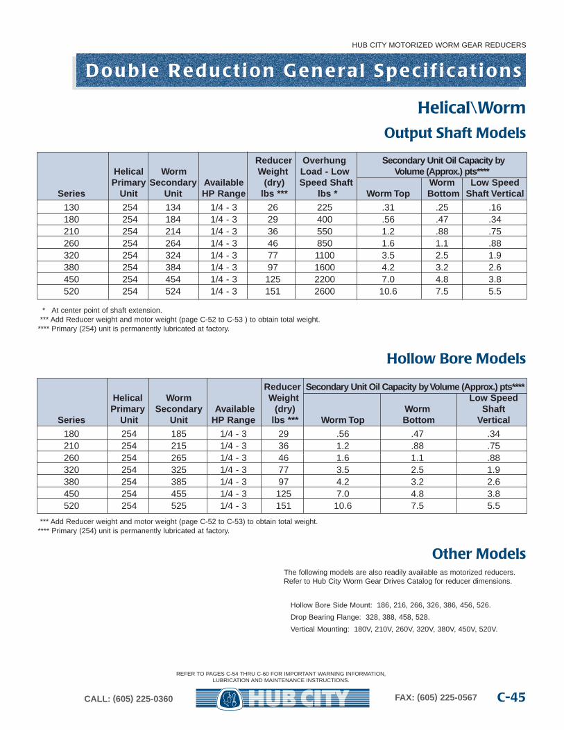
*** Add Reducer weight and motor weight (page C-52 to C-53) to obtain total weight.**** Primary (254) unit is permanently lubricated at factory.
HUB CITY MOTORIZED WORM GEAR REDUCERS
C-45CALL: (605) 225-0360 FAX: (605) 225-0567
Reducer Overhung Secondar y Unit Oil Capacity b y Helical Worm Weight Load - Lo w Volume (Appr ox.) pts****Primar y Secondar y Availab le (dry) Speed Shaft Worm Low Speed
Series Unit Unit HP Range lbs *** lbs * Worm Top Bottom Shaft Vertical
130 254 134 1/4 - 3 26 225 .31 .25 .16180 254 184 1/4 - 3 29 400 .56 .47 .34210 254 214 1/4 - 3 36 550 1.2 .88 .75260 254 264 1/4 - 3 46 850 1.6 1.1 .88320 254 324 1/4 - 3 77 1100 3.5 2.5 1.9380 254 384 1/4 - 3 97 1600 4.2 3.2 2.6450 254 454 1/4 - 3 125 2200 7.0 4.8 3.8520 254 524 1/4 - 3 151 2600 10.6 7.5 5.5
* At center point of shaft extension.*** Add Reducer weight and motor weight (page C-52 to C-53 ) to obtain total weight.
**** Primary (254) unit is permanently lubricated at factory.
Output Shaft Models
Reducer Secondar y Unit Oil Capacity b y Volume (Appr ox.) pts****Helical Worm Weight Low SpeedPrimar y Secondar y Availab le (dry) Worm Shaft
Series Unit Unit HP Range lbs *** Worm Top Bottom Vertical
180 254 185 1/4 - 3 29 .56 .47 .34210 254 215 1/4 - 3 36 1.2 .88 .75260 254 265 1/4 - 3 46 1.6 1.1 .88320 254 325 1/4 - 3 77 3.5 2.5 1.9380 254 385 1/4 - 3 97 4.2 3.2 2.6450 254 455 1/4 - 3 125 7.0 4.8 3.8520 254 525 1/4 - 3 151 10.6 7.5 5.5
Hollow Bore Models
Other ModelsThe following models are also readily available as motorized reducers.Refer to Hub City Worm Gear Drives Catalog for reducer dimensions.
Hollow Bore Side Mount: 186, 216, 266, 326, 386, 456, 526.
Drop Bearing Flange: 328, 388, 458, 528.
Vertical Mounting: 180V, 210V, 260V, 320V, 380V, 450V, 520V.
Helical\Worm
D o u b l e R e d u c t i o n G e n e ra l S p e c i f i c a t i o n s
REFER TO PAGES C-54 THRU C-60 FOR IMPORTANT WARNING INFORMATION,LUBRICATION AND MAINTENANCE INSTRUCTIONS.
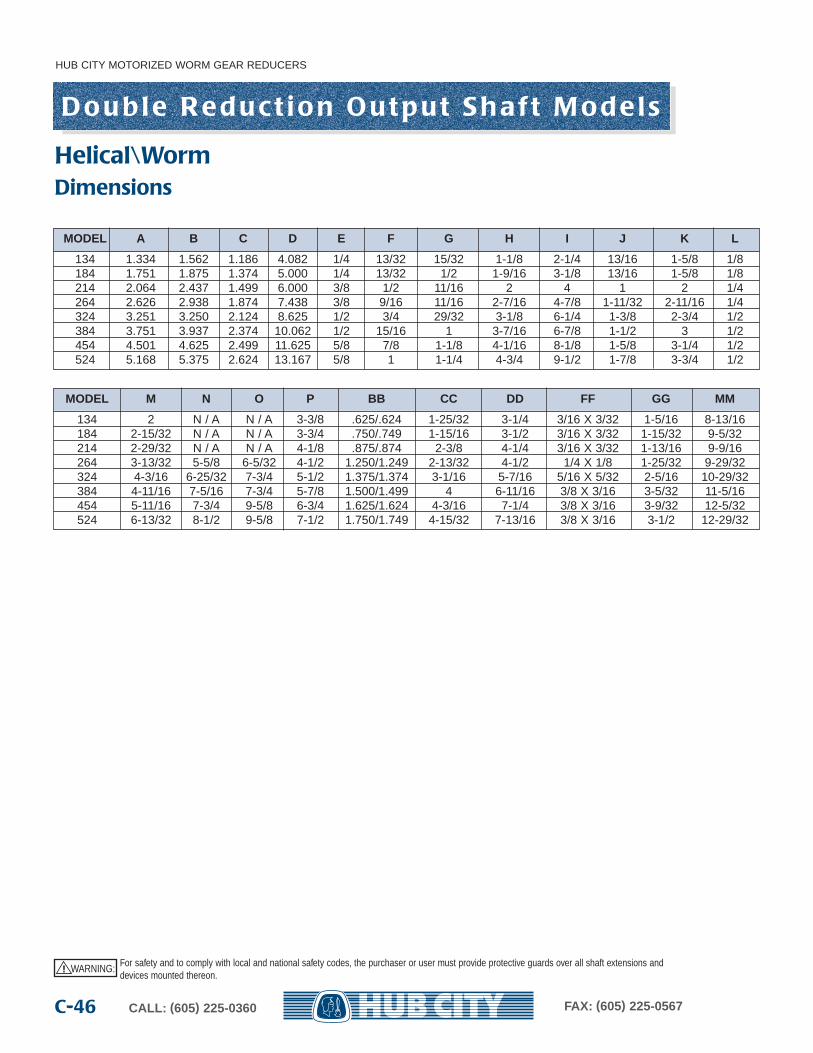
HUB CITY MOTORIZED WORM GEAR REDUCERS
CALL: (605) 225-0360 FAX: (605) 225-0567C-46
MODEL A B C D E F G H I J K L
134 1.334 1.562 1.186 4.082 1/4 13/32 15/32 1-1/8 2-1/4 13/16 1-5/8 1/8184 1.751 1.875 1.374 5.000 1/4 13/32 1/2 1-9/16 3-1/8 13/16 1-5/8 1/8214 2.064 2.437 1.499 6.000 3/8 1/2 11/16 2 4 1 2 1/4264 2.626 2.938 1.874 7.438 3/8 9/16 11/16 2-7/16 4-7/8 1-11/32 2-11/16 1/4324 3.251 3.250 2.124 8.625 1/2 3/4 29/32 3-1/8 6-1/4 1-3/8 2-3/4 1/2384 3.751 3.937 2.374 10.062 1/2 15/16 1 3-7/16 6-7/8 1-1/2 3 1/2454 4.501 4.625 2.499 11.625 5/8 7/8 1-1/8 4-1/16 8-1/8 1-5/8 3-1/4 1/2524 5.168 5.375 2.624 13.167 5/8 1 1-1/4 4-3/4 9-1/2 1-7/8 3-3/4 1/2
MODEL M N O P BB CC DD FF GG MM
134 2 N / A N / A 3-3/8 .625/.624 1-25/32 3-1/4 3/16 X 3/32 1-5/16 8-13/16184 2-15/32 N / A N / A 3-3/4 .750/.749 1-15/16 3-1/2 3/16 X 3/32 1-15/32 9-5/32214 2-29/32 N / A N / A 4-1/8 .875/.874 2-3/8 4-1/4 3/16 X 3/32 1-13/16 9-9/16264 3-13/32 5-5/8 6-5/32 4-1/2 1.250/1.249 2-13/32 4-1/2 1/4 X 1/8 1-25/32 9-29/32324 4-3/16 6-25/32 7-3/4 5-1/2 1.375/1.374 3-1/16 5-7/16 5/16 X 5/32 2-5/16 10-29/32384 4-11/16 7-5/16 7-3/4 5-7/8 1.500/1.499 4 6-11/16 3/8 X 3/16 3-5/32 11-5/16454 5-11/16 7-3/4 9-5/8 6-3/4 1.625/1.624 4-3/16 7-1/4 3/8 X 3/16 3-9/32 12-5/32524 6-13/32 8-1/2 9-5/8 7-1/2 1.750/1.749 4-15/32 7-13/16 3/8 X 3/16 3-1/2 12-29/32
Dimensions
WARNING: For safety and to comply with local and national safety codes, the purchaser or user must provide protective guards over all shaft extensions anddevices mounted thereon.
!
D o u b l e R e d u c t i o n O u t p u t S h a f t M o d e l s
Helical\Worm
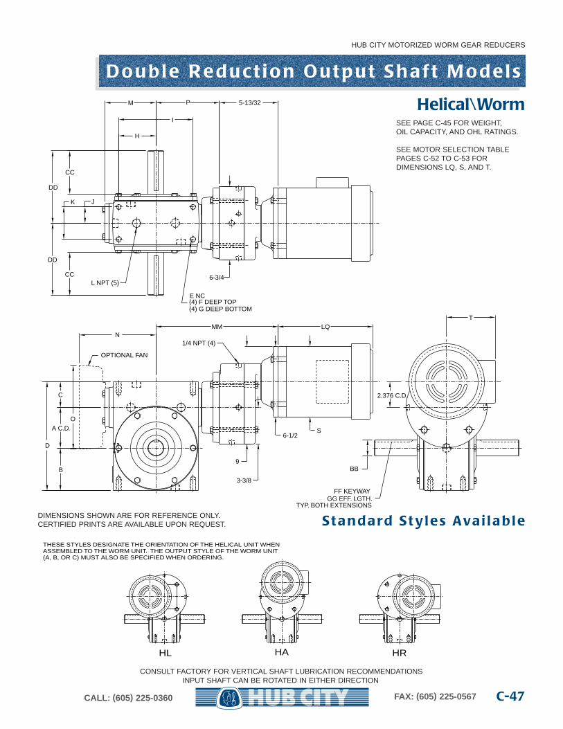
HUB CITY MOTORIZED WORM GEAR REDUCERS
C-47CALL: (605) 225-0360 FAX: (605) 225-0567
H
I
P
JK
CC
DD
FF KEYWAYGG EFF. LGTH.
TYP. BOTH EXTENSIONS
BB
M
E NC(4) F DEEP TOP(4) G DEEP BOTTOM
C
A C.D.
B
D
L NPT (5)
LQN
O
OPTIONAL FAN
2.376 C.D.
9
S6-1/2
TMM
3-3/8
6-3/4
1/4 NPT (4)
5-13/32
CC
DD
CONSULT FACTORY FOR VERTICAL SHAFT LUBRICATION RECOMMENDATIONSINPUT SHAFT CAN BE ROTATED IN EITHER DIRECTION
HAHL HR
THESE STYLES DESIGNATE THE ORIENTATION OF THE HELICAL UNIT WHENASSEMBLED TO THE WORM UNIT. THE OUTPUT STYLE OF THE WORM UNIT (A, B, OR C) MUST ALSO BE SPECIFIED WHEN ORDERING.
DIMENSIONS SHOWN ARE FOR REFERENCE ONLY.CERTIFIED PRINTS ARE AVAILABLE UPON REQUEST. S t a n d a rd S t y l e s Ava i l a b l e
SEE PAGE C-45 FOR WEIGHT,OIL CAPACITY, AND OHL RATINGS.
SEE MOTOR SELECTION TABLEPAGES C-52 TO C-53 FOR DIMENSIONS LQ, S, AND T.
D o u b l e R e d u c t i o n O u t p u t S h a f t M o d e l s
Helical\Worm
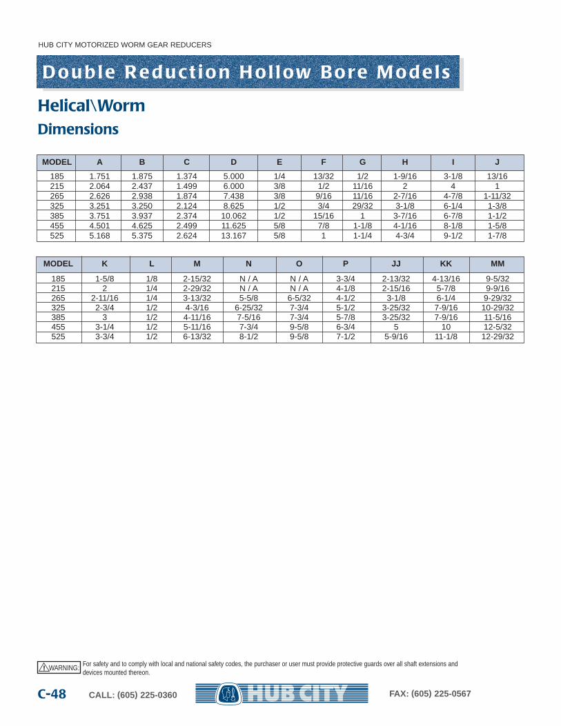
HUB CITY MOTORIZED WORM GEAR REDUCERS
CALL: (605) 225-0360 FAX: (605) 225-0567C-48
MODEL A B C D E F G H I J
185 1.751 1.875 1.374 5.000 1/4 13/32 1/2 1-9/16 3-1/8 13/16215 2.064 2.437 1.499 6.000 3/8 1/2 11/16 2 4 1265 2.626 2.938 1.874 7.438 3/8 9/16 11/16 2-7/16 4-7/8 1-11/32325 3.251 3.250 2.124 8.625 1/2 3/4 29/32 3-1/8 6-1/4 1-3/8385 3.751 3.937 2.374 10.062 1/2 15/16 1 3-7/16 6-7/8 1-1/2455 4.501 4.625 2.499 11.625 5/8 7/8 1-1/8 4-1/16 8-1/8 1-5/8525 5.168 5.375 2.624 13.167 5/8 1 1-1/4 4-3/4 9-1/2 1-7/8
MODEL K L M N O P JJ KK MM
185 1-5/8 1/8 2-15/32 N / A N / A 3-3/4 2-13/32 4-13/16 9-5/32215 2 1/4 2-29/32 N / A N / A 4-1/8 2-15/16 5-7/8 9-9/16265 2-11/16 1/4 3-13/32 5-5/8 6-5/32 4-1/2 3-1/8 6-1/4 9-29/32325 2-3/4 1/2 4-3/16 6-25/32 7-3/4 5-1/2 3-25/32 7-9/16 10-29/32385 3 1/2 4-11/16 7-5/16 7-3/4 5-7/8 3-25/32 7-9/16 11-5/16455 3-1/4 1/2 5-11/16 7-3/4 9-5/8 6-3/4 5 10 12-5/32525 3-3/4 1/2 6-13/32 8-1/2 9-5/8 7-1/2 5-9/16 11-1/8 12-29/32
Dimensions
WARNING: For safety and to comply with local and national safety codes, the purchaser or user must provide protective guards over all shaft extensions anddevices mounted thereon.
!
D o u b l e R e d u c t i o n H o l l ow B o re M o d e l s
Helical\Worm
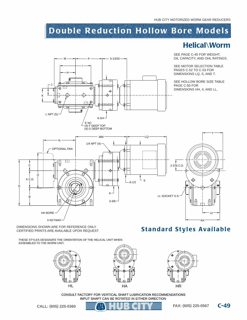
HUB CITY MOTORIZED WORM GEAR REDUCERS
C-49CALL: (605) 225-0360 FAX: (605) 225-0567
H
I
M P
J
K
JJ
KK
HH BORE
LL SOCKET S.S.
L NPT (5)
OPTIONAL FAN
N
O
D
A C.D.
B
C
E NC(4) F DEEP TOP(4) G DEEP BOTTOM
LQ
2.376 C.D.
9
S6-1/2
TMM
3-3/8
6-3/4
1/4 NPT (4)
5-13/32
II KEYWAY
CONSULT FACTORY FOR VERTICAL SHAFT LUBRICATION RECOMMENDATIONSINPUT SHAFT CAN BE ROTATED IN EITHER DIRECTION
HAHL HR
THESE STYLES DESIGNATE THE ORIENTATION OF THE HELICAL UNIT WHENASSEMBLED TO THE WORM UNIT.
DIMENSIONS SHOWN ARE FOR REFERENCE ONLY.CERTIFIED PRINTS ARE AVAILABLE UPON REQUEST. S t a n d a rd S t y l e s Ava i l a b l e
CONSULT FACTORY FOR VERTICAL SHAFT LUBRICATION RECOMMENDATIONSINPUT SHAFT CAN BE ROTATED IN EITHER DIRECTION
SEE PAGE C-45 FOR WEIGHT,OIL CAPACITY, AND OHL RATINGS.
SEE MOTOR SELECTION TABLEPAGES C-52 TO C-53 FOR DIMENSIONS LQ, S, AND T.
SEE HOLLOW BORE SIZE TABLEPAGE C-50 FOR DIMENSIONS HH, II, AND LL.
D o u b l e R e d u c t i o n H o l l ow B o re M o d e l s
Helical\Worm
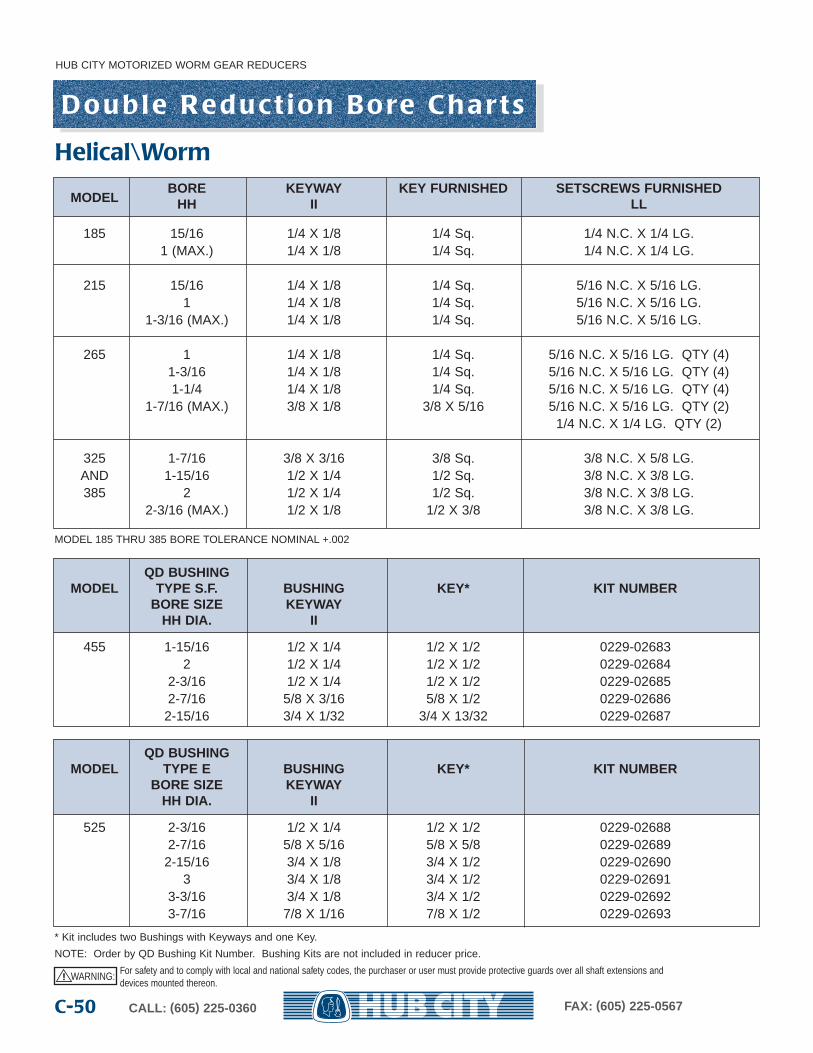
HUB CITY MOTORIZED WORM GEAR REDUCERS
CALL: (605) 225-0360 FAX: (605) 225-0567C-50
D o u b l e R e d u c t i o n B o re C h a r t s
MODELBORE KEYWAY KEY FURNISHED SETSCREWS FURNISHED
HH II LL
185 15/16 1/4 X 1/8 1/4 Sq. 1/4 N.C. X 1/4 LG.1 (MAX.) 1/4 X 1/8 1/4 Sq. 1/4 N.C. X 1/4 LG.
215 15/16 1/4 X 1/8 1/4 Sq. 5/16 N.C. X 5/16 LG.1 1/4 X 1/8 1/4 Sq. 5/16 N.C. X 5/16 LG.
1-3/16 (MAX.) 1/4 X 1/8 1/4 Sq. 5/16 N.C. X 5/16 LG.
265 1 1/4 X 1/8 1/4 Sq. 5/16 N.C. X 5/16 LG. QTY (4)1-3/16 1/4 X 1/8 1/4 Sq. 5/16 N.C. X 5/16 LG. QTY (4)1-1/4 1/4 X 1/8 1/4 Sq. 5/16 N.C. X 5/16 LG. QTY (4)
1-7/16 (MAX.) 3/8 X 1/8 3/8 X 5/16 5/16 N.C. X 5/16 LG. QTY (2) 1/4 N.C. X 1/4 LG. QTY (2)
325 1-7/16 3/8 X 3/16 3/8 Sq. 3/8 N.C. X 5/8 LG.AND 1-15/16 1/2 X 1/4 1/2 Sq. 3/8 N.C. X 3/8 LG.385 2 1/2 X 1/4 1/2 Sq. 3/8 N.C. X 3/8 LG.
2-3/16 (MAX.) 1/2 X 1/8 1/2 X 3/8 3/8 N.C. X 3/8 LG.
QD BUSHINGMODEL TYPE S.F. BUSHING KEY* KIT NUMBER
BORE SIZE KEYWAYHH DIA. II
455 1-15/16 1/2 X 1/4 1/2 X 1/2 0229-026832 1/2 X 1/4 1/2 X 1/2 0229-02684
2-3/16 1/2 X 1/4 1/2 X 1/2 0229-026852-7/16 5/8 X 3/16 5/8 X 1/2 0229-02686
2-15/16 3/4 X 1/32 3/4 X 13/32 0229-02687
QD BUSHINGMODEL TYPE E BUSHING KEY* KIT NUMBER
BORE SIZE KEYWAYHH DIA. II
525 2-3/16 1/2 X 1/4 1/2 X 1/2 0229-026882-7/16 5/8 X 5/16 5/8 X 5/8 0229-02689
2-15/16 3/4 X 1/8 3/4 X 1/2 0229-026903 3/4 X 1/8 3/4 X 1/2 0229-02691
3-3/16 3/4 X 1/8 3/4 X 1/2 0229-026923-7/16 7/8 X 1/16 7/8 X 1/2 0229-02693
MODEL 185 THRU 385 BORE TOLERANCE NOMINAL +.002
* Kit includes two Bushings with Keyways and one Key.
NOTE: Order by QD Bushing Kit Number. Bushing Kits are not included in reducer price.
WARNING: For safety and to comply with local and national safety codes, the purchaser or user must provide protective guards over all shaft extensions anddevices mounted thereon.
!
Helical\Worm
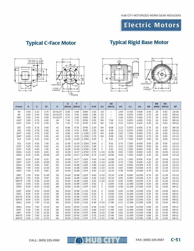
O P AB BB BDFrame D E 2F H (MAX) (MAX) U N-W AA (MAX) AH AJ AK BA (MIN) (MAX) BF
48 3.00 2.12 2.75 .34 SLOT 5.83 5.66 .5000 1.50 1/2 – 1.69 3.750 3.000 2.50 .16 5.62 1/4-2056 3.50 2.44 3.00 .34 SLOT 6.32 5.66 .6250 1.88 1/2 – 2.06 5.875 4.500 2.75 .16 6.50 3/8-16
56H 3.50 2.44 5.00 .34 SLOT 6.74 6.48 .6250 1.88 1/2 – 2.06 5.875 4.500 2.75 .16 6.50 3/8-16143T 3.50 2.75 4.00 .34 7.45 7.75 .8750 2.25 3/4 7.04 2.12 5.875 4.500 2.25 .16 6.50 3/8-16145T 3.50 2.75 5.00 .34 7.45 7.75 .8750 2.25 3/4 7.04 2.12 5.875 4.500 2.25 .16 6.50 3/8-16
182 4.50 3.75 4.50 .41 9.38 9.76 .8750 2.25 3/4 8.08 2.12 5.875 4.500 2.75 .16 6.50 3/8-16184 4.50 3.75 5.50 .41 9.38 9.76 .8750 2.25 3/4 8.08 2.12 5.875 4.500 2.75 .16 6.50 3/8-16
182T 4.50 3.75 4.50 .41 9.38 9.76 1.1250 2.75 3/4 8.08 2.62 7.250 8.500 2.75 .25 9.00 1/2-13184T 4.50 3.75 5.50 .41 9.38 9.76 1.1250 2.75 3/4 8.08 2.62 7.250 8.500 2.75 .25 9.00 1/2-13213 5.25 4.25 5.50 .41 11.00 11.50 1.1250 3.00 1 9.31 2.75 7.250 8.500 3.50 .25 9.00 1/2-13
215 5.25 4.25 7.00 .41 11.00 11.50 1.1250 3.00 1 9.31 2.75 7.250 8.500 3.50 .25 9.00 1/2-13213T 5.25 4.25 5.50 .41 11.00 11.50 1.3750 3.38 1 9.31 3.12 7.250 8.500 3.50 .25 9.00 1/2-13215T 5.25 4.25 7.00 .41 11.00 11.50 1.3750 3.38 1 9.31 3.12 7.250 8.500 3.50 .25 9.00 1/2-13254U 6.25 5.00 8.25 .53 14.09 14.27 1.3750 3.75 1-1/4 10.96 3.50 7.250 8.500 4.25 .25 10.00 1/2-13256U 6.25 5.00 10.00 .53 14.09 14.27 1.3750 3.75 1-1/4 10.96 3.50 7.250 8.500 4.25 .25 10.00 1/2-13
254T 6.25 5.00 8.25 .53 14.09 14.27 1.625 4.00 1-1/4 10.96 3.75 7.250 8.500 4.25 .25 10.00 1/2-13256T 6.25 5.00 10.00 .53 14.09 14.27 1.625 4.00 1-1/4 10.96 3.75 7.250 8.500 4.25 .25 10.00 1/2-13284U 7.00 5.50 9.50 .53 14.94 15.88 1.625 4.88 1-1/2 13.19 4.62 9.000 10.500 4.75 .25 11.25 1/2-13286U 7.00 5.50 11.00 .53 14.94 15.88 1.625 4.88 1-1/2 13.19 4.62 9.000 10.500 4.75 .25 11.25 1/2-13284T 7.00 5.50 9.50 .53 14.94 15.88 1.875 4.62 1-1/2 13.19 4.38 9.000 10.500 4.75 .25 11.25 1/2-13
286T 7.00 5.50 11.00 .53 14.94 15.88 1.875 4.62 1-1/2 13.19 4.38 9.000 10.500 4.75 .25 11.25 1/2-13284TS 7.00 5.50 9.50 .53 14.94 15.88 1.625 3.25 1-1/2 13.19 3.00 9.000 10.500 4.75 .25 11.25 1/2-13286TS 7.00 5.50 11.00 .53 14.94 15.88 1.625 3.25 1-1/2 13.19 3.00 9.000 10.500 4.75 .25 11.25 1/2-13324U 8.00 6.25 10.50 .66 15.93 15.88 1.875 5.62 2 13.69 5.38 11.000 12.500 5.25 .25 14.00 5/8-11326U 8.00 6.25 12.00 .66 15.93 15.88 1.875 5.62 2 13.69 5.38 11.000 12.500 5.25 .25 14.00 5/8-11
324T 8.00 6.25 10.50 .66 15.93 15.88 2.125 5.25 2 13.69 5.00 11.000 12.500 5.25 .25 14.00 5/8-11326T 8.00 6.25 12.00 .66 15.93 15.88 2.125 5.25 2 13.69 5.00 11.000 12.500 5.25 .25 14.00 5/8-11
324TS 8.00 6.25 10.50 .66 15.93 15.88 1.875 3.75 2 13.69 3.50 11.000 12.500 5.25 .25 14.00 5/8-11326TS 8.00 6.25 12.00 .66 15.93 15.88 1.875 3.75 2 13.69 3.50 11.000 12.500 5.25 .25 14.00 5/8-11364U 9.00 7.00 11.25 .66 19.00 20.00 2.125 6.38 2-1/2 17.88 6.12 11.000 12.500 5.88 .25 14.00 5/8-11
365U 9.00 7.00 12.25 .66 19.00 20.00 2.125 6.38 2-1/2 17.88 6.12 11.000 12.500 5.88 .25 14.00 5/8-11364T 9.00 7.00 11.25 .66 19.00 20.00 2.375 5.88 2-1/2 17.88 5.62 11.000 12.500 5.88 .25 14.00 5/8-11365T 9.00 7.00 12.25 .66 19.00 20.00 2.375 5.88 2-1/2 17.88 5.62 11.000 12.500 5.88 .25 14.00 5/8-11
364TS 9.00 7.00 11.25 .66 19.00 20.00 1.875 3.75 2-1/2 17.88 3.50 11.000 12.500 5.88 .25 14.00 5/8-11365TS 9.00 7.00 12.25 .66 19.00 20.00 1.875 3.75 2-1/2 17.88 3.50 11.000 12.500 5.88 .25 14.00 5/8-11
AK BD
BS2F
BA
BB
C
U
B
AHAH
(56-184)(213-449)
'H' DIA4 HOLES
AALEAD HOLE
AB
E
D+.00-.06
O
P
E
BF4 HOLES
45°45°
AJ
A
C
(B)
BS
2F
BA
U
N-W AB
E'H' DIA.4 HOLES
D+.00-.06
E
A
AALEAD HOLE
P
O
Typical C-Face Motor Typical Rigid Base Motor
E l e c t r i c M o t o r s
HUB CITY MOTORIZED WORM GEAR REDUCERS
C-51CALL: (605) 225-0360 FAX: (605) 225-0567
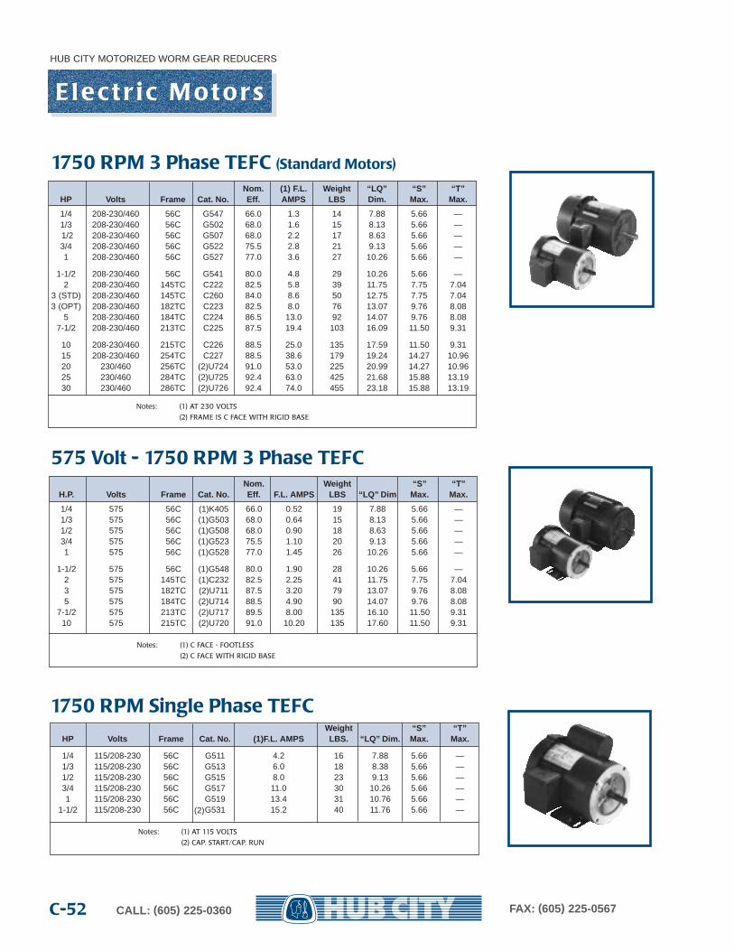
HUB CITY MOTORIZED WORM GEAR REDUCERS
CALL: (605) 225-0360 FAX: (605) 225-0567C-52
E l e c t r i c M o t o r s
Nom. Weight “S” “T”H.P. Volts Frame Cat. No. Eff . F.L. AMPS LBS “LQ” Dim Max. Max.
1/4 575 56C (1)K405 66.0 0.52 19 7.88 5.66 —1/3 575 56C (1)G503 68.0 0.64 15 8.13 5.66 —1/2 575 56C (1)G508 68.0 0.90 18 8.63 5.66 —3/4 575 56C (1)G523 75.5 1.10 20 9.13 5.66 —1 575 56C (1)G528 77.0 1.45 26 10.26 5.66 —
1-1/2 575 56C (1)G548 80.0 1.90 28 10.26 5.66 —2 575 145TC (1)C232 82.5 2.25 41 11.75 7.75 7.043 575 182TC (2)U711 87.5 3.20 79 13.07 9.76 8.085 575 184TC (2)U714 88.5 4.90 90 14.07 9.76 8.08
7-1/2 575 213TC (2)U717 89.5 8.00 135 16.10 11.50 9.3110 575 215TC (2)U720 91.0 10.20 135 17.60 11.50 9.31
Notes: (1) C FACE - FOOTLESS
(2) C FACE WITH RIGID BASE
Weight “S” “T”HP Volts Frame Cat. No. (1)F.L. AMPS LBS. “LQ” Dim. Max. Max.
1/4 115/208-230 56C G511 4.2 16 7.88 5.66 —1/3 115/208-230 56C G513 6.0 18 8.38 5.66 —1/2 115/208-230 56C G515 8.0 23 9.13 5.66 —3/4 115/208-230 56C G517 11.0 30 10.26 5.66 —1 115/208-230 56C G519 13.4 31 10.76 5.66 —
1-1/2 115/208-230 56C G531 15.2 40 11.76 5.66 —
Notes: (1) AT 115 VOLTS
(2) CAP. START/CAP. RUN
Nom. (1) F.L. Weight “LQ” “S” “T”HP Volts Frame Cat. No. Eff . AMPS LBS Dim. Max. Max.
1/4 208-230/460 56C G547 66.0 1.3 14 7.88 5.66 —1/3 208-230/460 56C G502 68.0 1.6 15 8.13 5.66 —1/2 208-230/460 56C G507 68.0 2.2 17 8.63 5.66 —3/4 208-230/460 56C G522 75.5 2.8 21 9.13 5.66 —1 208-230/460 56C G527 77.0 3.6 27 10.26 5.66 —
1-1/2 208-230/460 56C G541 80.0 4.8 29 10.26 5.66 —2 208-230/460 145TC C222 82.5 5.8 39 11.75 7.75 7.04
3 (STD) 208-230/460 145TC C260 84.0 8.6 50 12.75 7.75 7.043 (OPT) 208-230/460 182TC C223 82.5 8.0 76 13.07 9.76 8.08
5 208-230/460 184TC C224 86.5 13.0 92 14.07 9.76 8.087-1/2 208-230/460 213TC C225 87.5 19.4 103 16.09 11.50 9.31
10 208-230/460 215TC C226 88.5 25.0 135 17.59 11.50 9.3115 208-230/460 254TC C227 88.5 38.6 179 19.24 14.27 10.9620 230/460 256TC (2)U724 91.0 53.0 225 20.99 14.27 10.9625 230/460 284TC (2)U725 92.4 63.0 425 21.68 15.88 13.1930 230/460 286TC (2)U726 92.4 74.0 455 23.18 15.88 13.19
Notes: (1) AT 230 VOLTS
(2) FRAME IS C FACE WITH RIGID BASE
1750 RPM 3 Phase TEFC (Standard Motors)
575 Volt - 1750 RPM 3 Phase TEFC
1750 RPM Single Phase TEFC
(2)
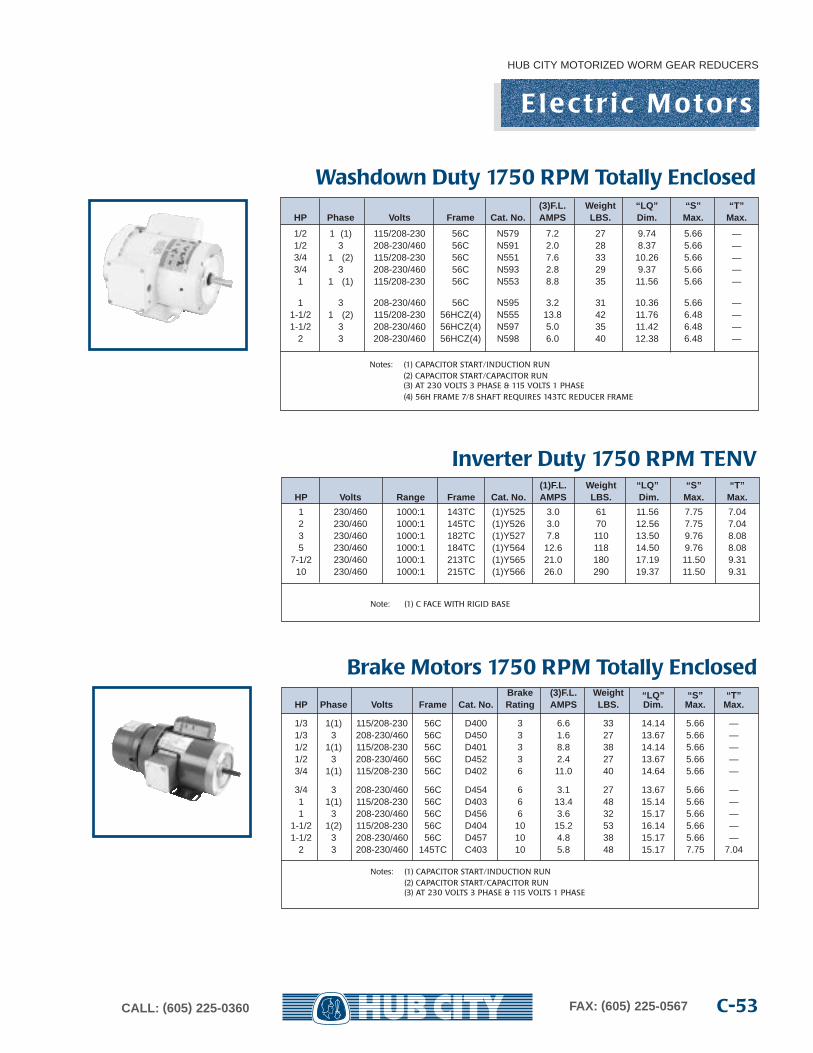
HUB CITY MOTORIZED WORM GEAR REDUCERS
C-53CALL: (605) 225-0360 FAX: (605) 225-0567
(1)F.L. Weight “LQ” “S” “T”HP Volts Range Frame Cat. No. AMPS LBS. Dim. Max. Max.
1 230/460 1000:1 143TC (1)Y525 3.0 61 11.56 7.75 7.042 230/460 1000:1 145TC (1)Y526 3.0 70 12.56 7.75 7.043 230/460 1000:1 182TC (1)Y527 7.8 110 13.50 9.76 8.085 230/460 1000:1 184TC (1)Y564 12.6 118 14.50 9.76 8.08
7-1/2 230/460 1000:1 213TC (1)Y565 21.0 180 17.19 11.50 9.3110 230/460 1000:1 215TC (1)Y566 26.0 290 19.37 11.50 9.31
Note: (1) C FACE WITH RIGID BASE
E l e c t r i c M o t o r s
(3)F.L. Weight “LQ” “S” “T”HP Phase Volts Frame Cat. No. AMPS LBS. Dim. Max. Max.
1/2 1 (1) 115/208-230 56C N579 7.2 27 9.74 5.66 —1/2 3 208-230/460 56C N591 2.0 28 8.37 5.66 —3/4 1 (2) 115/208-230 56C N551 7.6 33 10.26 5.66 —3/4 3 208-230/460 56C N593 2.8 29 9.37 5.66 —1 1 (1) 115/208-230 56C N553 8.8 35 11.56 5.66 —
1 3 208-230/460 56C N595 3.2 31 10.36 5.66 —1-1/2 1 (2) 115/208-230 56HCZ(4) N555 13.8 42 11.76 6.48 —1-1/2 3 208-230/460 56HCZ(4) N597 5.0 35 11.42 6.48 —
2 3 208-230/460 56HCZ(4) N598 6.0 40 12.38 6.48 —
Notes: (1) CAPACITOR START/INDUCTION RUN(2) CAPACITOR START/CAPACITOR RUN(3) AT 230 VOLTS 3 PHASE & 115 VOLTS 1 PHASE(4) 56H FRAME 7/8 SHAFT REQUIRES 143TC REDUCER FRAME
Brake (3)F.L. Weight “LQ” “S” “T”HP Phase Volts Frame Cat. No. Rating AMPS LBS. Dim. Max. Max.
1/3 1(1) 115/208-230 56C D400 3 6.6 33 14.14 5.66 —1/3 3 208-230/460 56C D450 3 1.6 27 13.67 5.66 —1/2 1(1) 115/208-230 56C D401 3 8.8 38 14.14 5.66 —1/2 3 208-230/460 56C D452 3 2.4 27 13.67 5.66 —3/4 1(1) 115/208-230 56C D402 6 11.0 40 14.64 5.66 —
3/4 3 208-230/460 56C D454 6 3.1 27 13.67 5.66 —1 1(1) 115/208-230 56C D403 6 13.4 48 15.14 5.66 —1 3 208-230/460 56C D456 6 3.6 32 15.17 5.66 —
1-1/2 1(2) 115/208-230 56C D404 10 15.2 53 16.14 5.66 —1-1/2 3 208-230/460 56C D457 10 4.8 38 15.17 5.66 —
2 3 208-230/460 145TC C403 10 5.8 48 15.17 7.75 7.04
Notes: (1) CAPACITOR START/INDUCTION RUN(2) CAPACITOR START/CAPACITOR RUN(3) AT 230 VOLTS 3 PHASE & 115 VOLTS 1 PHASE
Washdown Duty 1750 RPM Totally Enclosed
Inverter Duty 1750 RPM TENV
Brake Motors 1750 RPM Totally Enclosed
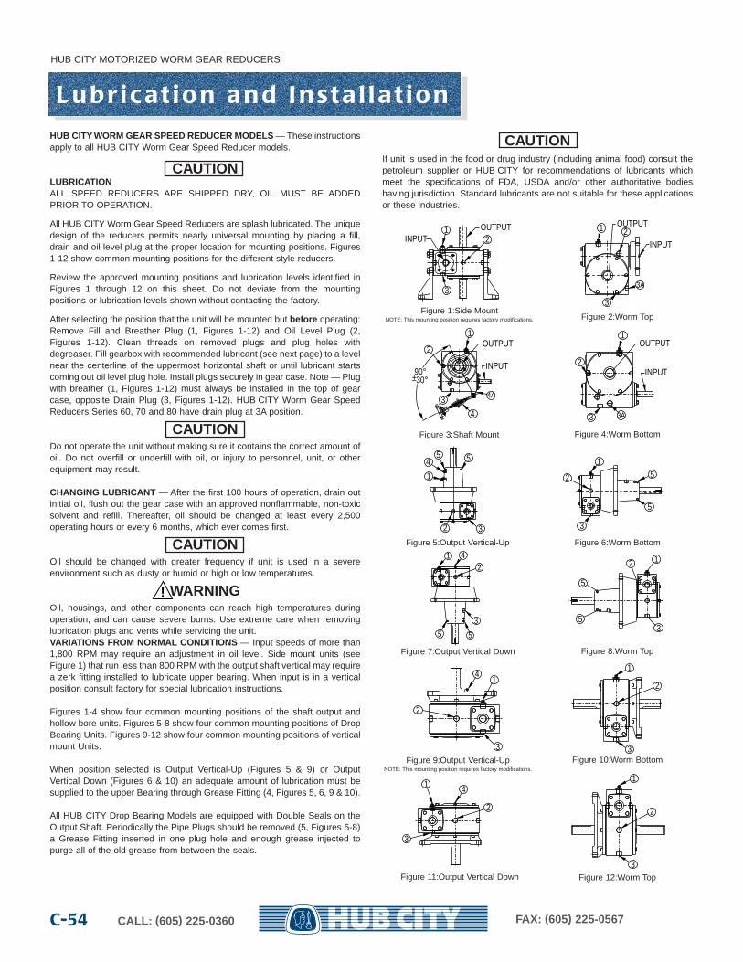
HUB CITY MOTORIZED WORM GEAR REDUCERS
CALL: (605) 225-0360 FAX: (605) 225-0567C-54
L u b r i c a t i o n a n d I n s t a l l a t i o nHUB CITY WORM GEAR SPEED REDUCER MODELS — These instructionsapply to all HUB CITY Worm Gear Speed Reducer models.
CAUTIONLUBRICATIONALL SPEED REDUCERS ARE SHIPPED DRY, OIL MUST BE ADDEDPRIOR TO OPERATION.
All HUB CITY Worm Gear Speed Reducers are splash lubricated. The uniquedesign of the reducers permits nearly universal mounting by placing a fill,drain and oil level plug at the proper location for mounting positions. Figures1-12 show common mounting positions for the different style reducers.
Review the approved mounting positions and lubrication levels identified inFigures 1 through 12 on this sheet. Do not deviate from the mountingpositions or lubrication levels shown without contacting the factory.
After selecting the position that the unit will be mounted but before operating:Remove Fill and Breather Plug (1, Figures 1-12) and Oil Level Plug (2,Figures 1-12). Clean threads on removed plugs and plug holes withdegreaser. Fill gearbox with recommended lubricant (see next page) to a levelnear the centerline of the uppermost horizontal shaft or until lubricant startscoming out oil level plug hole. Install plugs securely in gear case. Note — Plugwith breather (1, Figures 1-12) must always be installed in the top of gearcase, opposite Drain Plug (3, Figures 1-12). HUB CITY Worm Gear SpeedReducers Series 60, 70 and 80 have drain plug at 3A position.
CAUTIONDo not operate the unit without making sure it contains the correct amount ofoil. Do not overfill or underfill with oil, or injury to personnel, unit, or otherequipment may result.
CHANGING LUBRICANT — After the first 100 hours of operation, drain outinitial oil, flush out the gear case with an approved nonflammable, non-toxicsolvent and refill. Thereafter, oil should be changed at least every 2,500operating hours or every 6 months, which ever comes first.
CAUTIONOil should be changed with greater frequency if unit is used in a severeenvironment such as dusty or humid or high or low temperatures.
WARNINGOil, housings, and other components can reach high temperatures duringoperation, and can cause severe burns. Use extreme care when removinglubrication plugs and vents while servicing the unit.VARIATIONS FROM NORMAL CONDITIONS — Input speeds of more than1,800 RPM may require an adjustment in oil level. Side mount units (seeFigure 1) that run less than 800 RPM with the output shaft vertical may requirea zerk fitting installed to lubricate upper bearing. When input is in a verticalposition consult factory for special lubrication instructions.
Figures 1-4 show four common mounting positions of the shaft output andhollow bore units. Figures 5-8 show four common mounting positions of DropBearing Units. Figures 9-12 show four common mounting positions of verticalmount Units.
When position selected is Output Vertical-Up (Figures 5 & 9) or OutputVertical Down (Figures 6 & 10) an adequate amount of lubrication must besupplied to the upper Bearing through Grease Fitting (4, Figures 5, 6, 9 & 10).
All HUB CITY Drop Bearing Models are equipped with Double Seals on theOutput Shaft. Periodically the Pipe Plugs should be removed (5, Figures 5-8)a Grease Fitting inserted in one plug hole and enough grease injected topurge all of the old grease from between the seals.
CAUTIONIf unit is used in the food or drug industry (including animal food) consult thepetroleum supplier or HUB CITY for recommendations of lubricants whichmeet the specifications of FDA, USDA and/or other authoritative bodieshaving jurisdiction. Standard lubricants are not suitable for these applicationsor these industries.
!
OUTPUTINPUT
12
3
2
3A
3
INPUT
OUTPUT1
3
INPUT
OUTPUT1
2
4
4A
90°–30°+
3A3
INPUT
OUTPUT1
2
Figure 1:Side MountNOTE: This mounting position requires factory modifications. Figure 2:Worm Top
Figure 3:Shaft Mount Figure 4:Worm Bottom
1
45 5
2 3
Figure 5:Output Vertical-Up Figure 6:Worm Bottom
Figure 7:Output Vertical Down Figure 8:Worm Top
Figure 9:Output Vertical-UpNOTE: This mounting position requires factory modifications.
Figure 10:Worm Bottom
Figure 11:Output Vertical Down Figure 12:Worm Top
15
5
2
3
1
55
2
3
4 1
5
5
2
3
14
2
3
1
3
2
1 4
2
3
1
3
2
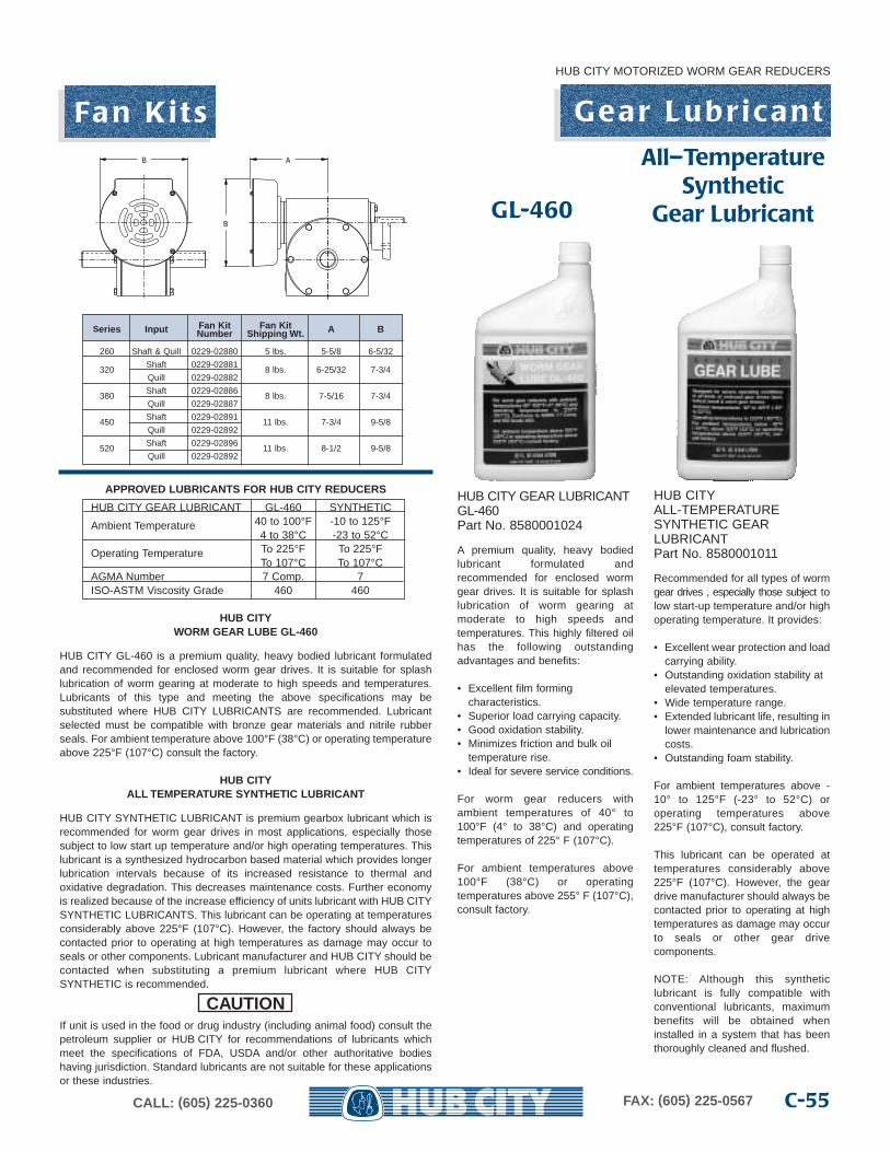
APPROVED LUBRICANTS FOR HUB CITY REDUCERS
HUB CITY GEAR LUBRICANT GL-460 SYNTHETIC
Ambient Temperature 40 to 100°F -10 to 125°F4 to 38°C -23 to 52°C
Operating Temperature To 225°F To 225°FTo 107°C To 107°C
AGMA Number 7 Comp. 7ISO-ASTM Viscosity Grade 460 460
HUB CITYWORM GEAR LUBE GL-460
HUB CITY GL-460 is a premium quality, heavy bodied lubricant formulatedand recommended for enclosed worm gear drives. It is suitable for splashlubrication of worm gearing at moderate to high speeds and temperatures.Lubricants of this type and meeting the above specifications may besubstituted where HUB CITY LUBRICANTS are recommended. Lubricantselected must be compatible with bronze gear materials and nitrile rubberseals. For ambient temperature above 100°F (38°C) or operating temperatureabove 225°F (107°C) consult the factory.
HUB CITYALL TEMPERATURE SYNTHETIC LUBRICANT
HUB CITY SYNTHETIC LUBRICANT is premium gearbox lubricant which isrecommended for worm gear drives in most applications, especially thosesubject to low start up temperature and/or high operating temperatures. Thislubricant is a synthesized hydrocarbon based material which provides longerlubrication intervals because of its increased resistance to thermal andoxidative degradation. This decreases maintenance costs. Further economyis realized because of the increase efficiency of units lubricant with HUB CITYSYNTHETIC LUBRICANTS. This lubricant can be operating at temperaturesconsiderably above 225°F (107°C). However, the factory should always becontacted prior to operating at high temperatures as damage may occur toseals or other components. Lubricant manufacturer and HUB CITY should becontacted when substituting a premium lubricant where HUB CITYSYNTHETIC is recommended.
CAUTIONIf unit is used in the food or drug industry (including animal food) consult thepetroleum supplier or HUB CITY for recommendations of lubricants whichmeet the specifications of FDA, USDA and/or other authoritative bodieshaving jurisdiction. Standard lubricants are not suitable for these applicationsor these industries.
GL-460
All–TemperatureSynthetic
Gear Lubricant
HUB CITY GEAR LUBRICANTGL-460Part No. 8580001024
A premium quality, heavy bodiedlubricant formulated andrecommended for enclosed wormgear drives. It is suitable for splashlubrication of worm gearing atmoderate to high speeds andtemperatures. This highly filtered oilhas the following outstandingadvantages and benefits:
• Excellent film formingcharacteristics.
• Superior load carrying capacity.• Good oxidation stability.• Minimizes friction and bulk oil
temperature rise.• Ideal for severe service conditions.
For worm gear reducers withambient temperatures of 40° to100°F (4° to 38°C) and operatingtemperatures of 225° F (107°C).
For ambient temperatures above100°F (38°C) or operatingtemperatures above 255° F (107°C),consult factory.
HUB CITYALL-TEMPERATURESYNTHETIC GEARLUBRICANTPart No. 8580001011
Recommended for all types of wormgear drives , especially those subject tolow start-up temperature and/or highoperating temperature. It provides:
• Excellent wear protection and loadcarrying ability.
• Outstanding oxidation stability atelevated temperatures.
• Wide temperature range.• Extended lubricant life, resulting in
lower maintenance and lubricationcosts.
• Outstanding foam stability.
For ambient temperatures above -10° to 125°F (-23° to 52°C) oroperating temperatures above225°F (107°C), consult factory.
This lubricant can be operated attemperatures considerably above225°F (107°C). However, the geardrive manufacturer should always becontacted prior to operating at hightemperatures as damage may occurto seals or other gear drive components.
NOTE: Although this synthetic lubricant is fully compatible withconventional lubricants, maximumbenefits will be obtained wheninstalled in a system that has beenthoroughly cleaned and flushed.
HUB CITY MOTORIZED WORM GEAR REDUCERS
C-55CALL: (605) 225-0360 FAX: (605) 225-0567
G e a r L u b r i c a n tA
B
B
Series Input Fan Kit Fan Kit A BNumber Shipping Wt.
260 Shaft & Quill 0229-02880 5 lbs. 5-5/8 6-5/32
320Shaft 0229-02881
8 lbs. 6-25/32 7-3/4Quill 0229-02882
380Shaft 0229-02886
8 lbs. 7-5/16 7-3/4Quill 0229-02887
450Shaft 0229-02891
11 lbs. 7-3/4 9-5/8Quill 0229-02892
520Shaft 0229-02896
11 lbs. 8-1/2 9-5/8Quill 0229-02892
Fa n K i t s
HUB CITY MOTORIZED WORM GEAR REDUCERS
CALL: (605) 225-0360 FAX: (605) 225-0567C-56
I n s t a l l a t i o n I n s t r u c t i o n sWARNING
SHIELD ALL R OTATING PARTSFor safety, purchaser or user must provide protective guards over all shaftextensions and any moving apparatus mounted on the unit. The uses isresponsible for checking and complying with all applicable safety codes in his areaand providing suitable shields.
WARNINGWear protective clothing and eye shields when installing or maintaining unit andmachine
WARNINGA unit cannot be used as an integral part of a machine superstructure which wouldimpose additional loads on the unit other than those imposed by the torque beingtransmitted, or by any shaft mounted power transmitting device such as sprockets,pulleys, or couplings.
WARNINGUnits ARE NOT to be considered fail safe or self locking devices. If these featuresare required, a properly sized, independent holding device must be utilized.
WARNINGAny brakes that are used in conjunction with a unit must be sized or positioned insuch a way so as to not subject the unit to loads beyond the capacities publishedin this catalog.
WARNINGMake certain that all tools and other items are clear from rotating parts beforestarting machine. Stand clear, and start machine slowly to be suer all componentsare secure and operating properly.
WARNINGMake certain that the power supply is disconnected before attempting to service orinstall the unit, or remove or install any components. Lock out the power supply,and tag it to prevent unexpected application of power.
OPERATING POSITIONS — Normal Speed Reducer positions are shown inFigures 1-12. For special applications, mounting position may be inclined.However, if position varies more than 15°, it may be necessary to make someadaptations to maintain a sufficient oil level. Contact your local distributor or HUBCITY for recommendations. Input rotation of Speed Reducers can be eitherclockwise or counterclockwise.
WARNINGFor safe operation and to continue the unit warranty, when installing,reinstalling, or replacing a factory installed fastener for servicing purpose, or toaccommodate the mounting of guards, shields or other light load imposing devices,or for mounting the unit, it becomes the responsibility of the purchaser or user toproperly determine the quality, grade of fastener, thread engagement, load carryingcapacity, tightening torque, and the means of torque retention.
COUPLINGS — Flexible couplings to input and output shafts are recommendedbecause they minimize bearing and gear wear caused by slight misalignment.Follow coupling manufacturer’s recommendations for installation and shielding.
SHEAVES AND SPROCKETS — When mounting sheaves or sprockets, thecenter of the load should be located as close to the reducer as possible. Excessiveoverhung loading could result in early failures of bearing or shaft. Refer to thegeneral catalog or contact your local distributor for overhung load ratings. Followmanufacturer’s recommendations for installation and shielding.
CAUTIONThe exterior threaded holes on this drive are for mounting the drive or drive acces-sories (couplings, sprockets, etc.). They are not to be used for lifting the drive orany driver/driven equipment.
CAUTIONInspect shafts and components for paint, burrs, or other imperfections beforeinstalling components. Do not use excessive force or pounding to installcomponents onto unit shafts, as this may cause damage to shafts, bearings, orgears.
SHAFT MOUNT UNITS — The Torque Arm Pad Ref. 4A (Figure 3) can be attachedto any of the four available mounting surface locations of the unit.
Install and position Torque Arm Ref. 4 at 90° to the place (a line drawn) betweenthe center of the output hollow bore and the bolt that attached the Torque Arm 4 tothe Torque Arm Pad 4A of the unit, Ref. (Figure 3). The Torque Arm should bepositioned to be in tension, NOT compression, based on output rotation of the geardrive.
CAUTIONExcessive setscrew torque may cause damage to the output sleeves inhollow bore units. Please refer to the following table for recommendedtightening torque.
Shaft Mount Reducers equipped with QD bushings utilize a bushing on both sidesto provide shaft support. However the keyways on QD bushings are not timed tothe mounting holes, therefore it is not possible to install keys in both bushings. Onekey is sufficient to carry the transmitted torque.
CAUTIONWhen installing Q/D Bushing Kits, follow the Q/D Bushing manufacturerrecommendations for bolt tightening torque and installation methods. Failure to doso could result in damage to the bushings and unit.
CAUTIONTest run unit to verify operation. If the unit being tested is a prototype, that unit mustbe of current production configuration.
RUN-IN PERIOD — A new unit will not operate at maximum efficiency during therun-in period. Increased current draw or heat rise may be seen during this time.
PREVENTATIVE MAINTENANCE — Keep shafts and vent plug clean to preventforeign particles from entering seals or gear case. Inspect periodically for oil leaks.
CAUTIONMounting bolts, coupling fasteners, and other power transmitting devices should beroutinely checked to ensure that all parts of the unit are firmly anchored to provideproper operation (loose fasteners can cause alignment problems and excessivewear). Check end play in shafts. Noticeable movement might indicate service orparts replacement is necessary.
CAUTIONIf the unit cannot be located in a clear and dry area with access to an adequatecooling air supply, then precautions must be taken to avoid ingestion of contami-nants such as water, and to avoid a reduction of cooling ability due to exterior con-taminants.
HUB CITY has Sales Offices and a network of Industrial Power TransmissionDistributors that can serve your needs world wide. Check the Yellow Pages for onenear you or contact the factory sales office.
IMPORTANT INFORMATIONIn the event of the resale of this Worm Gear Speed Reducer (unit), in whateverform, resellers/buyers will include the following language in a conspicuous placeand in a conspicuous manner in a written agreement covering such sale:
The manufacturer makes no warranty or representations, expressed or implied, byoperation of law or otherwise, as to the merchantability or fitness for a particularpurpose of the goods sold hereunder. Buyer acknowledges that it alone hasdetermined that the goods purchased hereunder will suitability meet therequirements of their intended use. In no event will manufacturer be liable forconsequential, incidental, or other damages.
Resellers/buyers agree to include this entire document, including the warnings andcautions listed herein, in a conspicuous place and in a conspicuous manner toinstruct users on the safe usage of the product.
!
!
!
!
!
!
!
!
Size Recommended Torque
1/4 NC 87 LB.–IN
5/16 NC 165 LB.–IN
3/8 NC 290 LB.–IN
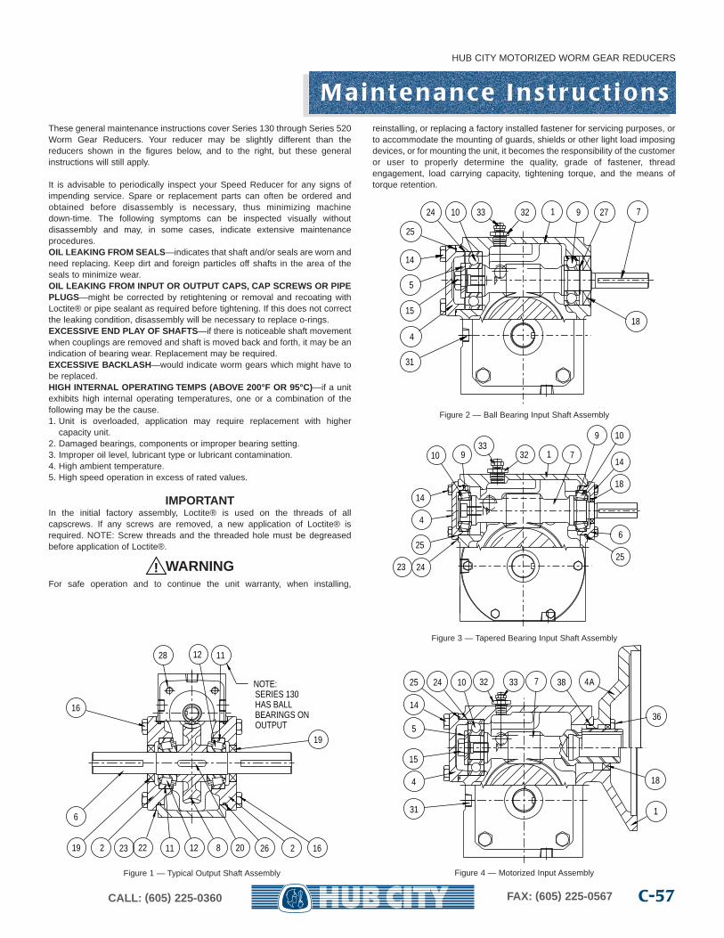
These general maintenance instructions cover Series 130 through Series 520Worm Gear Reducers. Your reducer may be slightly different than thereducers shown in the figures below, and to the right, but these generalinstructions will still apply.
It is advisable to periodically inspect your Speed Reducer for any signs ofimpending service. Spare or replacement parts can often be ordered andobtained before disassembly is necessary, thus minimizing machinedown-time. The following symptoms can be inspected visually withoutdisassembly and may, in some cases, indicate extensive maintenanceprocedures.OIL LEAKING FR OM SEALS—indicates that shaft and/or seals are worn andneed replacing. Keep dirt and foreign particles off shafts in the area of theseals to minimize wear.OIL LEAKING FR OM INPUT OR OUTPUT CAPS, CAP SCREWS OR PIPEPLUGS—might be corrected by retightening or removal and recoating withLoctite® or pipe sealant as required before tightening. If this does not correctthe leaking condition, disassembly will be necessary to replace o-rings.EXCESSIVE END PLAY OF SHAFTS—if there is noticeable shaft movementwhen couplings are removed and shaft is moved back and forth, it may be anindication of bearing wear. Replacement may be required.EXCESSIVE BACKLASH —would indicate worm gears which might have tobe replaced.HIGH INTERNAL OPERATING TEMPS (ABOVE 200°F OR 95°C)—if a unitexhibits high internal operating temperatures, one or a combination of thefollowing may be the cause.1. Unit is overloaded, application may require replacement with higher
capacity unit.2. Damaged bearings, components or improper bearing setting.3. Improper oil level, lubricant type or lubricant contamination.4. High ambient temperature.5. High speed operation in excess of rated values.
IMPORTANTIn the initial factory assembly, Loctite® is used on the threads of allcapscrews. If any screws are removed, a new application of Loctite® isrequired. NOTE: Screw threads and the threaded hole must be degreasedbefore application of Loctite®.
WARNINGFor safe operation and to continue the unit warranty, when installing,
reinstalling, or replacing a factory installed fastener for servicing purposes, orto accommodate the mounting of guards, shields or other light load imposingdevices, or for mounting the unit, it becomes the responsibility of the customeror user to properly determine the quality, grade of fastener, threadengagement, load carrying capacity, tightening torque, and the means oftorque retention.
!
NOTE: SERIES 130 HAS BALL BEARINGS ON OUTPUT
2223 11 12 8 20 26 2219
19
16
6
16
12 1128
3233 1 9 27
18
71024
25
14
5
15
4
31
25
4
24
14
23
3310 9 32 1
25
6
10
147
18
9
4A
36
18
387
1
3332102425
14
5
15
4
31
Figure 1 — Typical Output Shaft Assembly
Figure 2 — Ball Bearing Input Shaft Assembly
Figure 3 — Tapered Bearing Input Shaft Assembly
Figure 4 — Motorized Input Assembly
HUB CITY MOTORIZED WORM GEAR REDUCERS
C-57CALL: (605) 225-0360 FAX: (605) 225-0567
M a i n t e n a n c e I n s t r u c t i o n s
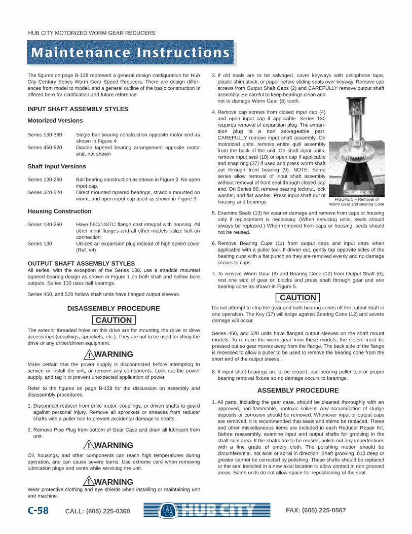
HUB CITY MOTORIZED WORM GEAR REDUCERS
CALL: (605) 225-0360 FAX: (605) 225-0567C-58
M a i n t e n a n c e I n s t r u c t i o n sThe figures on page B-128 represent a general design configuration for HubCity Century Series Worm Gear Speed Reducers. There are design differ-ences from model to model, and a general outline of the basic construction isoffered here for clarification and future reference:
INPUT SHAFT ASSEMBLY STYLES
Motoriz ed Versions
Series 130-380 Single ball bearing construction opposite motor end asshown in Figure 4.
Series 450-520 Double tapered bearing arrangement opposite motorend, not shown
Shaft Input Versions
Series 130-260 Ball bearing construction as shown in Figure 2. No openinput cap.
Series 320-520 Direct mounted tapered bearings, straddle mounted onworm, and open input cap used as shown in Figure 3.
Housing Construction
Series 130-260 Have 56C/143TC flange cast integral with housing. Allother input flanges and all other models utilize bolt-onconnection.
Series 130 Utilizes an expansion plug instead of high speed cover(Ref. #4)
OUTPUT SHAFT ASSEMBLY STYLESAll series, with the exception of the Series 130, use a straddle mountedtapered bearing design as shown in Figure 1 on both shaft and hollow boreoutputs. Series 130 uses ball bearings.
Series 450, and 520 hollow shaft units have flanged output sleeves.
DISASSEMBLY PROCEDURE
CAUTIONThe exterior threaded holes on this drive are for mounting the drive or driveaccessories (couplings, sprockets, etc.). They are not to be used for lifting thedrive or any driver/driven equipment.
WARNINGMake certain that the power supply is disconnected before attempting toservice or install the unit, or remove any components. Lock out the powersupply, and tag it to prevent unexpected application of power.
Refer to the figures on page B-128 for the discussion on assembly anddisassembly procedures.
1. Disconnect reducer from drive motor, couplings, or driven shafts to guardagainst personal injury. Remove all sprockets or sheaves from reducershafts with a puller tool to prevent accidental damage to shafts.
2. Remove Pipe Plug from bottom of Gear Case and drain all lubricant fromunit.
WARNINGOil, housings, and other components can reach high temperatures duringoperation, and can cause severe burns. Use extreme care when removinglubrication plugs and vents while servicing the unit.
WARNINGWear protective clothing and eye shields when installing or maintaining unitand machine.
3. If old seals are to be salvaged, cover keyways with cellophane tape,plastic shim stock, or paper before sliding seals over keyway. Remove capscrews from Output Shaft Caps (2) and CAREFULLY remove output shaftassembly. Be careful to keep bearings clean andnot to damage Worm Gear (8) teeth.
4. Remove cap screws from closed input cap (4)and open input cap if applicable. Series 130requires removal of expansion plug. The expan-sion plug is a non salvageable part. CAREFULLY remove input shaft assembly. Onmotorized units, remove entire quill assemblyfrom the back of the unit. On shaft input units,remove input seal (18) or open cap if applicableand snap ring (27) if used and press worm shaftout through front bearing (9). NOTE: Someseries allow removal of input shaft assemblywithout removal of front seal through closed capend. On Series 80, remove bearing locknut, lockwasher, and flat washer. Press input shaft out ofhousing and bearings.
5. Examine Seals (13) for wear or damage and remove from caps or housingonly if replacement is necessary. (When servicing units, seals shouldalways be replaced.) When removed from caps or housing, seals shouldnot be reused.
6. Remove Bearing Cups (11) from output caps and input caps whenapplicable with a puller tool. If driven out, gently tap opposite sides of thebearing cups with a flat punch so they are removed evenly and no damageoccurs to caps.
7. To remove Worm Gear (8) and Bearing Cone (12) from Output Shaft (6),rest one side of gear on blocks and press shaft through gear and onebearing cone as shown in Figure 5.
CAUTIONDo not attempt to strip the gear and both bearing cones off the output shaft inone operation. The Key (17) will lodge against Bearing Cone (12) and severedamage will occur.
Series 450, and 520 units have flanged output sleeves on the shaft mountmodels. To remove the worm gear from these models, the sleeve must bepressed out so gear moves away from the flange. The back side of the flangeis recessed to allow a puller to be used to remove the bearing cone from theshort end of the output sleeve.
8. If input shaft bearings are to be reused, use bearing puller tool or properbearing removal fixture so no damage occurs to bearings.
ASSEMBLY PROCEDURE
1. All parts, including the gear case, should be cleaned thoroughly with anapproved, non-flammable, nontoxic solvent. Any accumulation of sludgedeposits or corrosion should be removed. Whenever input or output capsare removed, it is recommended that seals and shims be replaced. Theseand other miscellaneous items are included in each Reducer Repair Kit.Before reassembly, examine input and output shafts for grooving in theshaft seal area. If the shafts are to be reused, polish out any imperfectionswith a fine grade of emery cloth. The polishing motion should becircumferential, not axial or spiral in direction. Shaft grooving .010 deep orgreater cannot be corrected by polishing. These shafts should be replacedor the seal installed in a new axial location to allow contact in non groovedareas. Some units do not allow space for repositioning of the seal.
!
!
!
FIGURE 5 – Removal ofWorm Gear and Bearing Cone
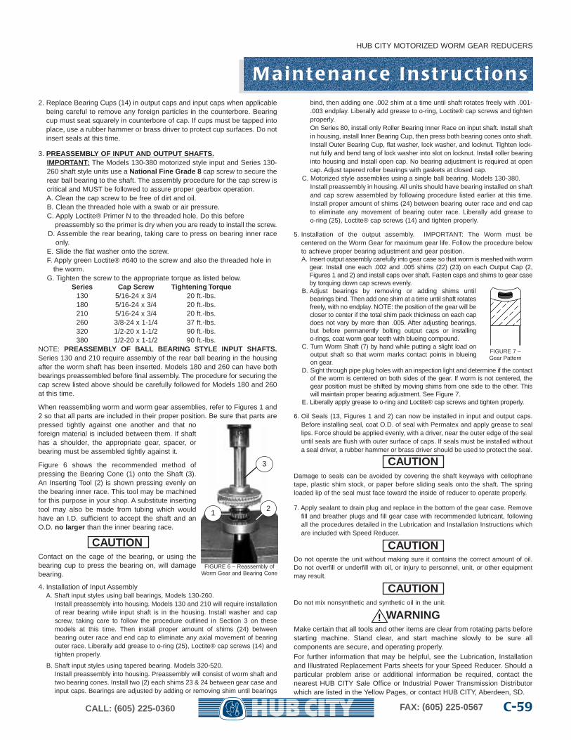
M a i n t e n a n c e I n s t r u c t i o n s
HUB CITY MOTORIZED WORM GEAR REDUCERS
C-59CALL: (605) 225-0360 FAX: (605) 225-0567
2. Replace Bearing Cups (14) in output caps and input caps when applicablebeing careful to remove any foreign particles in the counterbore. Bearingcup must seat squarely in counterbore of cap. If cups must be tapped intoplace, use a rubber hammer or brass driver to protect cup surfaces. Do notinsert seals at this time.
3. PREASSEMBLY OF INPUT AND OUTPUT SHAFTS.IMPORTANT: The Models 130-380 motorized style input and Series 130-260 shaft style units use a National Fine Grade 8 cap screw to secure therear ball bearing to the shaft. The assembly procedure for the cap screw iscritical and MUST be followed to assure proper gearbox operation.A. Clean the cap screw to be free of dirt and oil.B. Clean the threaded hole with a swab or air pressure.C. Apply Loctite® Primer N to the threaded hole. Do this before
preassembly so the primer is dry when you are ready to install the screw.D. Assemble the rear bearing, taking care to press on bearing inner race
only.E. Slide the flat washer onto the screw.F. Apply green Loctite® #640 to the screw and also the threaded hole in
the worm.G. Tighten the screw to the appropriate torque as listed below.
Series Cap Scre w Tightening Torque130 5/16-24 x 3/4 20 ft.-lbs.180 5/16-24 x 3/4 20 ft.-lbs.210 5/16-24 x 3/4 20 ft.-lbs.260 3/8-24 x 1-1/4 37 ft.-lbs.320 1/2-20 x 1-1/2 90 ft.-lbs.380 1/2-20 x 1-1/2 90 ft.-lbs.
NOTE: PREASSEMBLY OF BALL BEARING STYLE INPUT SHAFTS.Series 130 and 210 require assembly of the rear ball bearing in the housingafter the worm shaft has been inserted. Models 180 and 260 can have bothbearings preassembled before final assembly. The procedure for securing thecap screw listed above should be carefully followed for Models 180 and 260at this time.
When reassembling worm and worm gear assemblies, refer to Figures 1 and2 so that all parts are included in their proper position. Be sure that parts arepressed tightly against one another and that noforeign material is included between them. If shafthas a shoulder, the appropriate gear, spacer, orbearing must be assembled tightly against it.
Figure 6 shows the recommended method ofpressing the Bearing Cone (1) onto the Shaft (3).An Inserting Tool (2) is shown pressing evenly onthe bearing inner race. This tool may be machinedfor this purpose in your shop. A substitute insertingtool may also be made from tubing which wouldhave an I.D. sufficient to accept the shaft and anO.D. no lar ger than the inner bearing race.
CAUTIONContact on the cage of the bearing, or using thebearing cup to press the bearing on, will damagebearing.
4. Installation of Input AssemblyA. Shaft input styles using ball bearings, Models 130-260.
Install preassembly into housing. Models 130 and 210 will require installationof rear bearing while input shaft is in the housing. Install washer and capscrew, taking care to follow the procedure outlined in Section 3 on these models at this time. Then install proper amount of shims (24) between bearing outer race and end cap to eliminate any axial movement of bearingouter race. Liberally add grease to o-ring (25), Loctite® cap screws (14) andtighten properly.
B. Shaft input styles using tapered bearing. Models 320-520.Install preassembly into housing. Preassembly will consist of worm shaft andtwo bearing cones. Install two (2) each shims 23 & 24 between gear case andinput caps. Bearings are adjusted by adding or removing shim until bearings
bind, then adding one .002 shim at a time until shaft rotates freely with .001-.003 endplay. Liberally add grease to o-ring, Loctite® cap screws and tightenproperly.On Series 80, install only Roller Bearing Inner Race on input shaft. Install shaftin housing, install Inner Bearing Cup, then press both bearing cones onto shaft.Install Outer Bearing Cup, flat washer, lock washer, and locknut. Tighten lock-nut fully and bend tang of lock washer into slot on locknut. Install roller bearinginto housing and install open cap. No bearing adjustment is required at opencap. Adjust tapered roller bearings with gaskets at closed cap.
C. Motorized style assemblies using a single ball bearing. Models 130-380.Install preassembly in housing. All units should have bearing installed on shaftand cap screw assembled by following procedure listed earlier at this time.Install proper amount of shims (24) between bearing outer race and end capto eliminate any movement of bearing outer race. Liberally add grease to o-ring (25), Loctite® cap screws (14) and tighten properly.
5. Installation of the output assembly. IMPORTANT: The Worm must becentered on the Worm Gear for maximum gear life. Follow the procedure belowto achieve proper bearing adjustment and gear position.A. Insert output assembly carefully into gear case so that worm is meshed with worm
gear. Install one each .002 and .005 shims (22) (23) on each Output Cap (2,Figures 1 and 2) and install caps over shaft. Fasten caps and shims to gear caseby torquing down cap screws evenly.
B. Adjust bearings by removing or adding shims untilbearings bind. Then add one shim at a time until shaft rotatesfreely, with no endplay. NOTE: the position of the gear will becloser to center if the total shim pack thickness on each capdoes not vary by more than .005. After adjusting bearings,but before permanently bolting output caps or installingo-rings, coat worm gear teeth with blueing compound.
C. Turn Worm Shaft (7) by hand while putting a slight load onoutput shaft so that worm marks contact points in blueingon gear.
D. Sight through pipe plug holes with an inspection light and determine if the contactof the worm is centered on both sides of the gear. If worm is not centered, thegear position must be shifted by moving shims from one side to the other. Thiswill maintain proper bearing adjustment. See Figure 7.
E. Liberally apply grease to o-ring and Loctite® cap screws and tighten properly.
6. Oil Seals (13, Figures 1 and 2) can now be installed in input and output caps.Before installing seal, coat O.D. of seal with Permatex and apply grease to seallips. Force should be applied evenly, with a driver, near the outer edge of the sealuntil seals are flush with outer surface of caps. If seals must be installed withouta seal driver, a rubber hammer or brass driver should be used to protect the seal.
CAUTIONDamage to seals can be avoided by covering the shaft keyways with cellophanetape, plastic shim stock, or paper before sliding seals onto the shaft. The springloaded lip of the seal must face toward the inside of reducer to operate properly.
7. Apply sealant to drain plug and replace in the bottom of the gear case. Removefill and breather plugs and fill gear case with recommended lubricant, followingall the procedures detailed in the Lubrication and Installation Instructions whichare included with Speed Reducer.
CAUTIONDo not operate the unit without making sure it contains the correct amount of oil.Do not overfill or underfill with oil, or injury to personnel, unit, or other equipmentmay result.
CAUTIONDo not mix nonsynthetic and synthetic oil in the unit.
WARNINGMake certain that all tools and other items are clear from rotating parts beforestarting machine. Stand clear, and start machine slowly to be sure allcomponents are secure, and operating properly.For further information that may be helpful, see the Lubrication, Installationand Illustrated Replacement Parts sheets for your Speed Reducer. Should aparticular problem arise or additional information be required, contact thenearest HUB CITY Sale Office or Industrial Power Transmission Distributorwhich are listed in the Yellow Pages, or contact HUB CITY, Aberdeen, SD.
FIGURE 6 – Reassembly ofWorm Gear and Bearing Cone
12
3
FIGURE 7 – Gear Pattern
!
The follo wing and inf ormation is supplied to y ou f or y our pr otection and to pr ovideyou with man y years of tr oub le free and saf e operation of y our Hub City pr oduct.
Read ALL instructions prior to operating reducer. Injury to personnel or reducer failure may be caused by improper installation, maintenance or operation.
• Written authorization from Hub City is required to operate or use reducers in man lift or people moving devices.
• Check to make certain application does not exceed the allowable load capacities published in the current catalog.
• Buyer shall be solely responsible for determining the adequacy of the product for any and all usesto which Buyer shall apply the product. The application by Buyer shall not be subject to any impliedwarranty of fitness for a particular purpose.
• For safety, Buyer or User should provide protective guards over all shaft extensions and any moving apparatus mounted thereon. The User is responsible for checking all applicable safetycodes in his area and providing suitable guards. Failure to do so may result in bodily injury and/ordamage to equipment.
• Hot oil or reducers can cause severe burns. Use extreme care when removing lubrication plugsand vents.
• Make certain that the power supply is disconnected before attempting to service or remove any components. Lock out the power supply and tag it to prevent unexpected application of power.
• Reducers are not to be considered fail safe or self-locking devices. If these features are required,a properly sized, independent holding device should be utilized. Reducers should not be used asa brake.
• Any brakes that are used in conjunction with a reducer must be sized or positioned in such a wayso as to not subject the reducer to loads beyond the catalog rating.
• Lifting supports including eyebolts are to be used for vertically lifting the gearbox only and no otherassociated attachments or motors.
• Use of an oil with an EP additive on units with backstops may prevent proper operation of the back-stop. Injury to personnel, reducer or other equipment may result.
• Test run unit to verify operation. If the unit tested is a prototype, that unit must be of current production.
• If the speed reducer cannot be located in a clear and dry area with access to adequate cooling air supply, then precautions must be taken to avoid the ingestion of contaminants such as water andthe reduction in cooling ability due to exterior contaminants.
• Mounting bolts should be routinely checked to ensure that the unit is firmly anchored for proper operation.
In the event of the resale of any of the goods, in whatever form, Resellers/Buyers will include the following language in aconspicuous place and in a conspicuous manner in a written agreement covering such sale:
The manufacturer makes no warranty or representations, express or implied, by operation of law or otherwise, as to the merchantability or fitness for a particular purpose of the goods sold hereunder. Buyeracknowledges that it alone has determined that the goods purchased hereunder will suitably meet therequirements of their intended use. In no event will the manufacturer be liable for consequential, incidental or other damages.
Reseller/Buyers agree to also include this entire document including the warnings above in a conspicuous place and in aconspicuous manner in writing to instruct users on the safe usage of the product.
This information should be read together with all other printed information supplied by Hub City.
IMPORTANT INFORMATIONPlease Read Carefull yWARNING
WARNING
WARNING
CAUTION
CAUTION
CALL: (605) 225-0360 FAX: (605) 225-0567C-60
CAUTION
HUB CITY MOTORIZED WORM GEAR REDUCERS
C-61CALL: (605) 225-0360 FAX: (605) 225-0567
Te r m s & Co n d i t i o n s o f S a l e s
1. AGREEMENT AND MODIFICATION OF SALES TERMS. The agreementbetween Seller and Buyer (“Sales Contract”) is with respect to the sale of goodsdescribed on the other side hereof (the “goods”). Any Terms and Conditionscontained in any purchase order or other form of communication from Seller'scustomers which are additional to or different from these Terms and Conditionsshall be deemed rejected by Seller unless expressly accepted in writing by Seller. 2. ACCEPTANCE OF ORDERS. Acceptance by Seller of Buyer’s purchase order(s)is expressly conditioned upon Buyer’s assent to these Terms and Conditions.Buyer will be deemed to have assented to such Terms and Conditions unlessSeller receives written notice of any objections within 10 days after Buyer's receiptof this form or in all events prior to any delivery or other performance by Seller ofBuyer's order if less than 10 days.3. QUOTATIONS. Quotations by Seller shall be deemed to be offers by Seller tosell the goods described therein subject to these Terms and Conditions, andacceptance of such offers is expressly limited to acceptance by Buyer of all ofthese Terms and Conditions within 30 days from the date of the quotation or asspecified. Purchase orders submitted by Buyer for the goods quoted by Sellershall be subject to and will be deemed to constitute acceptance of these Termsand Conditions. All purchase orders will be subject to approval by Seller.4. TERMINATION OR MODIFICATION. The Sales Contract may be modified orterminated only upon Seller’s express written consent, which consent will at alltimes be conditioned on Buyer’s agreement to pay Seller’s modification ortermination charge including, but not limited to expenses and costs plus areasonable profit, except that any goods completed on or before Seller’sacceptance of termination shall be accepted and paid in full by Buyer.5. PRICES AND TERMS. Fulfillment of Buyer’s order is contingent upon theavailability of materials. The price of the goods sold pursuant to the Sales Contractshall be based upon Seller's prices in effect at the time of shipment and anyacceptance of the order will be on the basis of the freight rates now in effect. Inthe event of an increase or decrease in the applicable freight charges before thematerial is shipped, such changes in freight charges will be for the account ofBuyer. Price advances, discounts, extras and terms and conditions are subject tochanges without notice. Unless otherwise provided on the front side hereof, priceis F.O.B. Seller’s point of shipment, and terms of payment shall be net 30 daysfrom date of invoice. Seller may assess a delinquency charge of 1-1/2 percent permonth on invoices not paid within stated payment terms. Seller may require fullor partial payment or payment guarantees in advance of shipment whenever, inits opinion, the financial condition of Buyer so warrants. In addition, Seller may,at any time, suspend performance of any order or require payment in cash, security or other adequate assurance satisfactory to Seller when, in Seller’sopinion, the financial condition of Buyer warrants such action.6. TAXES. Prices do not include sales, use or other similar federal, state or localtaxes. Buyer shall pay to Seller, in addition to the price of the goods, allapplicable taxes which may be invoiced separately at a later date.7. DESIGN; EXTRA WORK; BUYER'S MATERIAL.(a) If any order accepted by Seller contemplates the preparation of specialdesigns by Seller, Buyer issuing such order will have a responsiblerepresentative specifically approve all designs prepared by Seller.(b) If Buyer requests extra work not included in the quotation ororiginal order, Buyer will pay for the extra work at reasonable rates as determinedby Seller. (c) In the event spoilage/damage occurs on orders where Buyerfurnishes the material, Seller shall not be liable for replacement of or damage tosuch material.8. RISK OF LOSS, TITLE, SECURITY INTEREST. Delivery shall occur, and risk ofloss shall pass to Buyer, upon delivery of the material to acarrier at the F.O.B. point of shipment. Transportation shall be at Buyer's sole riskand expense, and any claims for losses or damage in transit shall be against thecarrier only. However, Seller retains title to all products until paid for in full in cashand Buyer agrees to perform all acts necessary to provide a fully perfectedsecurity interest in the goods in favor of Seller. Seller may, at Seller’s option,repossess the same, upon Buyer's default in payment hereunder, and chargeBuyer with any deficiency. 9. DELIVERIES AND QUANTITIES.(a) Delivery dates are not guaranteed but are estimated on the basis ofimmediate receipt by Seller of all information to be furnished by Buyer and theabsence of delay, direct or indirect, resulting from or contributed to bycircumstances beyond Seller's reasonable control. If the goods arenon-catalog goods, Seller may ship overages or underages to the extent of 10
percent of quantity ordered, and Buyer shall pay for such quantity based upon theunit price of the goods. Seller shall not be required to maintain closer control ofquantity, unless specifically agreed to by Seller in writing. Quantities of all itemsmay be determined by weight. Any claims for shortage must be within 10 daysfrom the date of receipt of the goods by Buyer, and in every case the weightsfound in any particular shipment, including tare, must be given and Seller advisedas to the method used by Buyer in computing the count of part parts.(b) In the event that Buyer is unable to accept delivery of the goods at time ofshipment, Seller shall invoice Buyer for the full purchase price as if shipment hadbeen made and: (i) if Seller is able to store such goods in its own facilities, Buyerwill pay Seller the reasonable handling and storage charges for the period of suchstorage, and (ii) if Seller is unable to store such goods at its own facility, Sellerreserves the right to arrange handling and storage in a suitable bondedwarehouse for the Buyer at Buyer's expense. In cases where handling andstorage become necessary, it shall be Buyer's responsibility to notify Seller whenshipment is to be made. Seller will make for shipment at Buyer’s expense.necessary arrangements for shipment at Buyer’s expense.10. RETURNED GOODS. Goods may not be returned. However, if Seller consentsin writing or upon verbal authorization to the return of goods for any reason,transportation charges must be prepaid by Buyer, who also shall assume all riskof loss of such returned goods until actual receipt by Seller. 11. INSPECTION, ACCEPTANCE. Buyer shall inspect the goods immediately uponthe receipt thereof. All claims by Buyer (including claims for shortages), exceptonly those provided for under the WARRANTY AND LIMITATIONS OF LIABILITY andPATENTS clauses below, must be asserted in writing by Buyer within a 10 dayperiod or they are waived. If this contract involves partial performances, all suchclaims must be asserted within a 10 day period for each partial performance.Rejection may be only for defects substantially impairing the value of products orwork. Buyer’s remedy for lesser defects shall be those provided for under theWarranty and Liability clauses. THERE SHALL BE NO REVOCATION OFACCEPTANCE. If Buyer wrongfully rejects, revokes or delays acceptance of itemsor work tendered under this contract, or fails to make a payment due on or beforedelivery, or repudiates this contract, Seller shall, at its option, have a right to recover as damages, either the price as stated herein (upon recovery of the price,the items involved shall become the property of the Buyer) or the profit(including reasonable overhead) which the Seller would make from performancetogether with incidental damages and reasonable cost.12. WARRANTIES AND LIMITATIONS OF LIABILITY.(a) Seller warrants to Buyer that the goods will conform to the followingwarranty: The goods will be commercially free from defects in material andworkmanship under normal use for a period of 1 year from the date of shipmentof the goods by Seller and will conform at the date of shipment to applicable specifications, drawings and blueprints, except for departures therefrom withwritten approval of Buyer; provided that work performed by Seller upon blanksand other materials furnished by Buyer is excluded from this warranty. Seller shallhave no liability to Buyer for cost of blanks furnished by Buyer which are damagedor spoiled during heat treat or machining operations; (b) In the case of drives, gears and reducers manufactured by Seller, Sellerwarrants only that such products, when shipped, shall be capable of delivering theservice rating as indicated in Seller’s written documents, including quotations andcatalogs or as noted on such products, providing such equipment is properlyinstalled and maintained, correctly lubricated, operating under normal conditionswith competent supervision, and within the load limits for which it was sold, andprovided further that the equipment is free from critical speed, tortional or othertype vibration, no matter how induced; (c) If any model or sample was provided to the Buyer, it was used merely toillustrate the general type and quality of goods and not to warrant that goodsshipped would be of that type or quality; (d) UNLESS AUTHORIZED IN WRITING BY A CORPORATE OFFICER OR VICEPRESIDENT, NO AGENT, EMPLOYEE OR REPRESENTATIVE OF SELLER HAS ANYAUTHORITY TO BIND SELLER TO ANY AFFIRMATION, REPRESENTATION ORWARRANTY CONCERNING THE GOODS SOLD UNDER THE SALES CONTRACT ANDANY SUCH AFFIRMATION, REPRESENTATION OR WARRANTY HAS NOT FORMED APART OF THE BASIS OF THE BARGAIN AND SHALL BE UNENFORCEABLE; (e) Seller’s sole obligation under the foregoing warranties is limited to either, atSeller’s option, replacing or repairing defective goods (or defective parts thereof).This warranty does not cover the cost of installation of the new or repaired goodsor parts. Replacement goods or parts are warranted for the remainder of the warranty period applicable to the goods originally supplied by Seller. All claims
QUOTATIONS ARE MADE AND ORDERS ARE ACCEPTED BY SELLER SUBJECT ONLY TO THESE TERMS AND CONDITIONS:
HUB CITY MOTORIZED WORM GEAR REDUCERS
CALL: (605) 225-0360 FAX: (605) 225-0567C-62
Te r m s & Co n d i t i o n s o f S a l e s
for allegedly defective goods must be made within 10 days after Buyer learns ofsuch alleged defects. All claims not made in writing and received by Seller withinsuch 10 day period shall be deemed waived. Buyer shall return a sample of thealleged defective part for Seller's inspection, and no other goods shall be returnedto Seller without Seller’s written consent. This warranty shall not extend to goodssubjected to misuse, abuse, neglect, accident or improper installation ormaintenance, incorrect lubrication, or goods which have been altered or repairedby anyone other than Seller or its authorized representative; (f) THE FOREGOING WARRANTIES ARE EXCLUSIVE AND IN LIEU OF ALL OTHERWARRANTIES OF MERCHANTABILITY, FITNESS FOR A PARTICULAR PURPOSEAND/OR ANY OTHER TYPE, WHETHER EXPRESS OR IMPLIED; (g) Products manufactured and work not performed by Seller are warranted onlyto the extent and in the manner that the same are warranted to Seller by Seller'svendors, and then only to the extent that Seller is reasonably able to enforce suchwarranty. In enforcing such warranty, it is understood Seller shall have noobligation to initiate litigation unless Buyer undertakes to pay all costs andexpenses therefor, including but not limited to Attorney’s fees, and indemnifiesSeller against any liability to Seller's vendors arising out of such litigation; (h) THE FOREGOING IS SELLER’S ONLY OBLIGATION AND BUYER’S EXCLUSIVEREMEDY FOR BREACH OF WARRANTY. BUYER’S FAILURE TO SUBMIT A CLAIM ASPROVIDED ABOVE SHALL SPECIFICALLY WAIVE ALL CLAIMS FOR DAMAGES OROTHER RELIEF INCLUDING BUT NOT LIMITED TO CLAIMS BASED ON LATENTDEFECTS. IN NO EVENT SHALL BUYER BE ENTITLED TO INCIDENTAL,CONSEQUENTIAL, OR SPECIAL DAMAGES, NOR SHALL SELLER’S LIABILITY EXCEEDTHE PURCHASE PRICE OF THE GOODS. ANY ACTION ARISING HEREUNDER ORRELATED HERETO MUST BE COMMENCED WITHIN ONE (1) YEAR AFTER THECAUSE OF ACTION OCCURS OR IT SHALL BE BARRED, NOTWITHSTANDING ANYSTATUTORY PERIOD OF LIMITATIONS TO THE CONTRARY; and (i) In the event of theresale of any of the goods, in whatever form, Buyer will include the following language in a conspicuous place and in a conspicuous manner in awritten agreement covering such resale: “THE MANUFACTURER MAKES NOWARRANTIES OR REPRESENTATIONS, EXPRESS OR IMPLIED, BY OPERATION OFLAW OR OTHERWISE, AS TO THE MERCHANTABILITY OR FITNESS FOR APARTICULAR PURPOSE OF THE GOODS SOLD HEREUNDER. BUYERACKNOWLEDGES THAT IT ALONE HAS DETERMINED THAT THE GOODSPURCHASED HEREUNDER WILL SUITABLY MEET THE REQUIREMENTS OF THEIRINTENDED USE. IN NO EVENT WILL MANUFACTURER BE LIABLE FOR CONSEQUENTIAL, INCIDENTAL OR OTHER DAMAGES.”13. REMEDIES AND LIMITATIONS OF LIABILITY. In the event Buyer claims Sellerhas breached any of its obligations under the Sales Contract, whether of warranty or otherwise, Seller may request the return of goods and tender to Buyer,at Seller's option, a replacement shipment of goods. If Seller so requests the returnof the goods, the goods will be redelivered to Seller in accordance with Seller’sinstructions and at Buyer’s expense. Except as herein provided, Seller shall have nofurther obligation under the Sales Contract. The remedies contained in thisparagraph and paragraph 12 hereof shall constitute the sole recourse of Buyeragainst Seller for breach of any of Seller’s obligations under the Sales Contract,whether warranty or otherwise.14. TECHNICAL ADVICE. Any technical advice furnished or recommendationmade by Seller or any representative of Seller concerning any use or application ofany of the goods is believed to be reliable, but SELLER MAKES NO WARRANTY,EXPRESSED OR IMPLIED, ON RESULTS TO BE OBTAINED. BUYER ASSUMES ALLRESPONSIBILITY FOR LOSS OR DAMAGE RESULTING FROM THE HANDLING ORUSE OF ANY OF THE GOODS.15. FORCE MAJEURE. Seller shall not be liable for failure to perform itsobligations under the Sales Contract in whole or in part caused by the occurrence
of any contingencies beyond the reasonable control either of Seller or of suppliersof Seller. If any such contingency occurs, Seller may allocate goods and deliveriesamong Seller's customers.16. ASSIGNMENT AND DELEGATION. No right or interest in the Sales Contractshall be assigned by Buyer without Seller’s prior written consent, and nodelegation of any obligation owed, or to the performance of any obligation byBuyer shall be made without Seller’s prior written consent. Any attempt atassignment or delegation shall be wholly void and totally ineffective for all purposes unless made in conformity with this paragraph.17. PATTERNS AND TOOLING. Unless otherwise agreed to in writing with Buyer,Seller shall retain title to and possession of all special tooling, patterns and dieswhether paid for by Buyer or not, but such special tooling, patterns and dies thatare specifically paid for by Buyer will be held by Seller exclusively for the manufacture of Buyer's goods for not more than 2 years after the date of Buyer'slast order requiring their use. Seller will exercise reasonable care in handling and storing any tooling, patterns or dies specifically paid for by Buyer, but Seller shall notbe liable for damage or loss thereof.18. PATENTS. SELLER MAKES NO REPRESENTATION OR WARRANTY WITHRESPECT TO THE PATENTABILITY OF THE GOODS OR THAT ANY OF THE GOODSWILL BE FREE FROM CLAIMS OF INFRINGEMENT. Buyer agrees to indemnify anddefend Seller in any such suit, action or proceeding for any claim resulting fromactual or alleged infringement of any domestic or foreign letters patent for (i) anyfeature, construction or design incorporated at Buyer’s request in any goods or toadapt such goods to the particular use of Buyer or Buyer's customers or (ii) anyadditions, changes or adaptations made by Buyer or Buyer's customers afterdelivery of the goods.19. CONFIDENTIAL INFORMATION. All drawings, diagrams, specifications,technical data and other materials furnished by Seller and identified by Seller asconfidential are and shall remain the exclusive property of Seller and shall bereturned to Seller upon request. Buyer agrees to treat such information andmaterial as confidential and not to reproduce or disclose such information ormaterials without Seller’s prior written consent. This paragraph does not apply toany information already known to and readily accessible in the trade or which maybecome so through no fault of Buyer.20. CHANGES. Seller may, at any time, without notice, make changes (whether indesign, material, improvements or otherwise) in any catalog goods, and may discontinue the manufacture of any catalog goods, all in its sole discretion,without incurring any obligations of any kind as a result thereof, whether forfailure to fill an order of Buyer or otherwise.21. INSTALLATION. Installation of the goods shall be by Buyer unless otherwisespecifically stated in the Sales Contract.22. SEVERABILITY. If any term or provision contained in the Sales Contract isdeclared or held invalid by a court of competent jurisdiction, such declaration orholding shall not affect the validity of any other term, clause or provision contained herein.23. GOVERNING LAW AND LIMITATION. (a) The formation and performance of theSales Contract shall be deemed to have been made and governed by the UniformCommercial Code as adopted in the state of Seller's principal place of business; (b) Buyer hereby agrees to the jurisdiction of any state or federal court located inthe county of Seller's principal place of business. Buyer waives any objection basedon forum non conveniens and any objection to venue of any action institutedhereunder, and consents to the granting of such legal or equitable relief as isdeemed appropriate by a court of competent jurisdiction; and (c) Seller represents that the goods will be produced in compliance with the FairLabor Standards Act of 1938, as amended.