Embed Size (px)
Citation preview
HX3 Blaster Plus User Guide
Doc. No. 001-90185 Rev. *B
Cypress Semiconductor
198 Champion Court
San Jose, CA 95134-1709
Phone (USA): +1.800.858.1810
Phone (Intnl): +1.408.943.2600
http://www.cypress.com
Copyrights
HX3 Blaster Plus User Guide, Doc. No. 001-90185 Rev. *B 2
Copyrights
© Cypress Semiconductor Corporation, 2014. The information contained herein is subject to change without notice. Cypress Semiconductor Corporation assumes no responsibility for the use of any circuitry other than circuitry embodied in a Cypress product. Nor does it convey or imply any license under patent or other rights. Cypress products are not warranted nor intended to be used for medical, life support, life saving, critical control or safety applications, unless pursuant to an express written agreement with Cypress. Furthermore, Cypress does not authorize its products for use as critical components in life-support systems where a malfunction or failure may reasonably be expected to result in significant injury to the user. The inclusion of Cypress products in life-support systems application implies that the manufacturer assumes all risk of such use and in doing so indemnifies Cypress against all charges.
Source Code
Any Source Code (software and/or firmware) is owned by Cypress Semiconductor Corporation (Cypress) and is protected by and subject to worldwide patent protection (United States and foreign), United States copyright laws and international treaty provisions. Cypress hereby grants to licensee a personal, non-exclusive, non-transferable license to copy, use, modify, create derivative works of, and compile the Cypress Source Code and derivative works for the sole purpose of creating custom software and or firmware in support of licensee product to be used only in conjunction with a Cypress integrated circuit as specified in the applicable agreement. Any reproduction, modification, translation, compilation, or representation of this Source Code except as specified above is prohibited without the express written permission of Cypress.
Disclaimer
CYPRESS MAKES NO WARRANTY OF ANY KIND, EXPRESS OR IMPLIED, WITH REGARD TO THIS MATERIAL, INCLUDING, BUT NOT LIMITED TO, THE IMPLIED WARRANTIES OF MERCHANTABILITY AND FITNESS FOR A PARTICULAR PURPOSE. Cypress reserves the right to make changes without further notice to the materials described herein. Cypress does not assume any liability arising out of the application or use of any product or circuit described herein. Cypress does not authorize its products for use as critical components in life-support systems where a malfunction or failure may reasonably be expected to result in significant injury to the user. The inclusion of Cypress’ product in a life-support systems application implies that the manufacturer assumes all risk of such use and in doing so indemnifies Cypress against all charges.
Use may be limited by and subject to the applicable Cypress software license agreement.
Trademarks
Purchase of I2C components from Cypress or one of its sublicensed Associated Companies conveys a license under the Philips I2C Patent Rights to use these components in an I2C system, provided that the system conforms to the I2C Standard Specification as defined by Philips. As from October 1st, 2006 Philips Semiconductors has a new trade name - NXP Semiconductors. All trademarks or registered trademarks referenced herein are property of the respective corporations.
Flash Code Protection
Cypress products meet the specifications contained in their particular Cypress Datasheets. Cypress believes that its family of products is one of the most secure families of its kind on the market today, regardless of how they are used. There may be methods, unknown to Cypress, that can breach the code protection features. Any of these methods, to our knowledge, would be dishonest and possibly illegal. Neither Cypress nor any other semiconductor manufacturer can guarantee the security of their code. Code protection does not mean that we are guaranteeing the product as "unbreakable." Cypress is willing to work with the customer who is concerned about the integrity of their code. Code protection is constantly evolving. We at Cypress are committed to continuously improving the code protection features of our products.
HX3 Blaster Plus User Guide, Doc. No. 001-90185 Rev. *B 3
Contents
1. Introduction .................................................................................................................................................................... 4 1.1 Getting Started ...................................................................................................................................................... 4 1.2 Additional Learning Resources .............................................................................................................................. 4 1.3 Technical Support .................................................................................................................................................. 4 1.4 Document Conventions ......................................................................................................................................... 4 1.5 Abbreviations ......................................................................................................................................................... 5
2. Software Installation ..................................................................................................................................................... 6 2.1 HX3 Blaster Plus Software .................................................................................................................................... 6 2.2 Install Hardware ..................................................................................................................................................... 7 2.3 Uninstall Software .................................................................................................................................................. 7
3. HX3 Blaster Plus Tool ................................................................................................................................................... 8 3.1 Overview ............................................................................................................................................................... 8 3.2 Setup ..................................................................................................................................................................... 8 3.3 Procedure to Run HX3 Blaster Plus ...................................................................................................................... 9
3.3.1 Connect HX3-Based Hardware to a PC .................................................................................................... 9 3.3.2 Install CYUSBHX3 Vendor Driver on a PC ............................................................................................... 9 3.3.3 Perform Configuration Using the HX3 Blaster Plus Tool ......................................................................... 15 3.3.4 Generating I2C slave mode file to configure a HX3 hardware in I2C slave mode .................................. 22 3.3.5 Uninstall CYUSBHX3 Vendor Driver ....................................................................................................... 23
4. Troubleshooting .......................................................................................................................................................... 24 4.1 Troubleshooting Guide ........................................................................................................................................ 24
HX3 Blaster Plus User Guide, Doc. No. 001-90185 Rev. *B 4
1. Introduction
Thank you for your interest in the HX3 Blaster Plus tool. This is a Windows-based tool that enables configuring HX3 features on hardware with an I2C EEPROM attached to HX3.
1.1 Getting Started This user guide describes the features of the HX3 Blaster Plus tool and how to use it. The HX3 Blaster Plus Tool section explains the procedure to use the tool. The Troubleshooting section lists the troubleshooting procedure.
1.2 Additional Learning Resources Visit the HX3 web page at www.cypress.com/hx3 for additional learning resources including datasheets and application notes.
1.3 Technical Support For assistance, go to www.cypress.com/go/support or contact our live customer support at +1 (800) 858-1810 (in the U.S.) or +1 (408) 943-2600 (international) and follow the voice prompt.
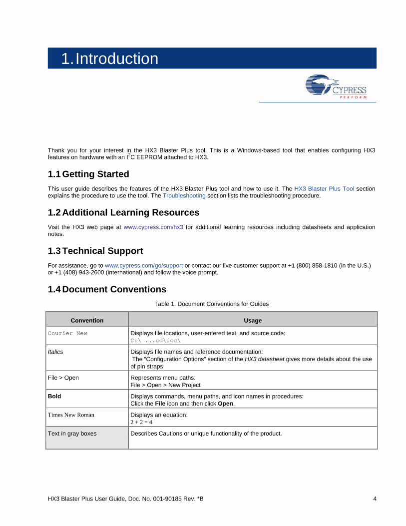
1.4 Document Conventions Table 1. Document Conventions for Guides
Convention Usage
Courier New Displays file locations, user-entered text, and source code: C:\ ...cd\icc\
Italics Displays file names and reference documentation: The “Configuration Options” section of the HX3 datasheet gives more details about the use of pin straps
File > Open Represents menu paths: File > Open > New Project
Bold Displays commands, menu paths, and icon names in procedures: Click the File icon and then click Open.
Times New Roman Displays an equation: 2 + 2 = 4
Text in gray boxes Describes Cautions or unique functionality of the product.
0BIntroduction
HX3 Blaster Plus User Guide, Doc. No. 001-90185 Rev. *B 5
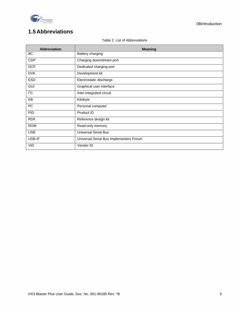
1.5 Abbreviations Table 2. List of Abbreviations
Abbreviation Meaning BC Battery charging
CDP Charging downstream port
DCP Dedicated charging port
DVK Development kit
ESD Electrostatic discharge
GUI Graphical user interface
I2C Inter-integrated circuit
KB Kilobyte
PC Personal computer
PID Product ID
RDK Reference design kit
ROM Read-only memory
USB Universal Serial Bus
USB-IF Universal Serial Bus Implementers Forum
VID Vendor ID
HX3 Blaster Plus User Guide, Doc. No. 001-90185 Rev. *B 6
2. Software Installation
2.1 HX3 Blaster Plus Software Follow these steps to install the Hx3 Blaster Plus tool on a Windows PC:
1. Download the tool package from www.cypress.com/go/hx3blasterplus and start the installation. The tool package is available in the following installer formats for download:
HX3 Blaster Plus Setup (HX3BlasterPlusSetup.exe): This installation package contains the files related to the tool. It does not include the Windows installer and Microsoft .NET Framework packages. If these packages are not installed on your computer, the installer automatically redirects to the Internet to download the packages. Run the .exe file after downloading to start the installation.
HX3 Blaster Plus ISO (HX3BlasterPlus.iso): This file is a complete package stored in a CD-ROM image format that you can use to create a CD or extract the file using an ISO extraction program such as WinZip or WinRAR, so that you can run cyautorun.exe to start the installation. This file includes the HX3 Blaster Plus tool, HX3 Blaster Plus User Guide, and Release Notes.
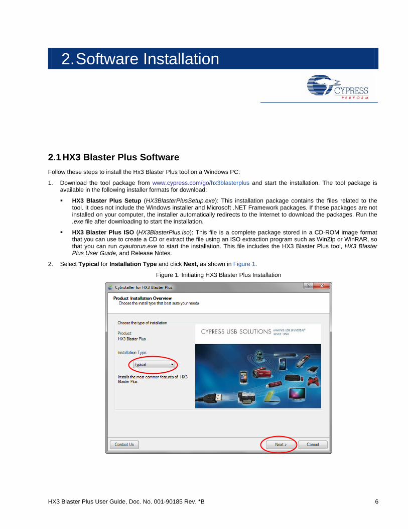
2. Select Typical for Installation Type and click Next, as shown in Figure 1.
Figure 1. Initiating HX3 Blaster Plus Installation
Software Installation
HX3 Blaster Plus User Guide, Doc. No. 001-90185 Rev. *B 7
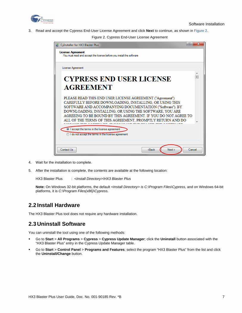
3. Read and accept the Cypress End-User License Agreement and click Next to continue, as shown in Figure 2.
Figure 2. Cypress End-User License Agreement
4. Wait for the installation to complete.
5. After the installation is complete, the contents are available at the following location: HX3 Blaster Plus : <Install Directory>\HX3 Blaster Plus Note: On Windows 32-bit platforms, the default <Install Directory> is C:\Program Files\Cypress, and on Windows 64-bit platforms, it is C:\Program Files(x86)\Cypress.
2.2 Install Hardware The HX3 Blaster Plus tool does not require any hardware installation.
2.3 Uninstall Software You can uninstall the tool using one of the following methods:
Go to Start > All Programs > Cypress > Cypress Update Manager; click the Uninstall button associated with the “HX3 Blaster Plus” entry in the Cypress Update Manager table.
Go to Start > Control Panel > Programs and Features; select the program “HX3 Blaster Plus” from the list and click the Uninstall/Change button.
HX3 Blaster Plus User Guide, Doc. No. 001-90185 Rev. *B 8
3. HX3 Blaster Plus Tool
This section describes the capabilities of the HX3 Blaster Plus tool and the procedure to run the tool with an HX3-based hardware or kit. It uses CY4609, CY4603, and CY4613 hardware as a reference; however, the same procedure can be used on any HX3-based hardware.
3.1 Overview HX3 Blaster Plus is a GUI-based tool to configure the HX3 hub controller. It can be used to configure any HX3-based hardware with a compatible EEPROM connected to HX3 over I2C. This tool allows you to do the following:
Read configuration data from the EEPROM and display the values.
Download custom firmware from a PC via HX3 and store it on the EEPROM.
Download custom firmware and configuration data together and store it on the EEPROM.
Configure HX3 and download only the configuration data to the EEPROM.
Erase the firmware and configuration data from the EEPROM.
Generate HX3 configuration data to be sent over the I2C bus when HX3 is configured as an I2C slave.
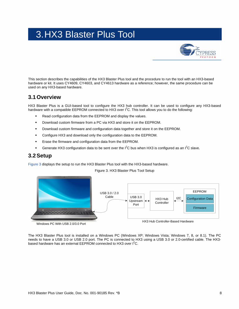
3.2 Setup Figure 3 displays the setup to run the HX3 Blaster Plus tool with the HX3-based hardware.
Figure 3. HX3 Blaster Plus Tool Setup
HX3 Hub Controller
EEPROM
I2CUSB 3.0 Upstream
Port
Configuration Data
Firmware
Windows PC With USB 2.0/3.0 Port HX3 Hub Controller-Based Hardware
USB 3.0 / 2.0 Cable
The HX3 Blaster Plus tool is installed on a Windows PC (Windows XP; Windows Vista; Windows 7, 8, or 8.1). The PC needs to have a USB 3.0 or USB 2.0 port. The PC is connected to HX3 using a USB 3.0 or 2.0-certified cable. The HX3-based hardware has an external EEPROM connected to HX3 over I2C.
HX3 Blaster Plus Tool
HX3 Blaster Plus User Guide, Doc. No. 001-90185 Rev. *B 9
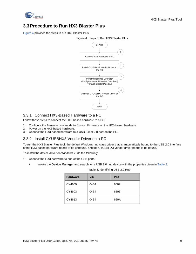
3.3 Procedure to Run HX3 Blaster Plus Figure 4 provides the steps to run HX3 Blaster Plus.
Figure 4. Steps to Run HX3 Blaster Plus
START
END
Install CYUSBHX3 Vendor Driver on the PC
Perform Required Operation (Configuration or Firmware Download)
Through Blaster Plus GUI
Connect HX3 Hardware to PC
Uninstall CYUSBHX3 Vendor Driver on the PC
1
2
3
4
3.3.1 Connect HX3-Based Hardware to a PC Follow these steps to connect the HX3-based hardware to a PC:
1. Configure the firmware boot mode to Custom Firmware on the HX3-based hardware. 2. Power on the HX3-based hardware. 3. Connect the HX3-based hardware to a USB 3.0 or 2.0 port on the PC.
3.3.2 Install CYUSBHX3 Vendor Driver on a PC To run the HX3 Blaster Plus tool, the default Windows hub class driver that is automatically bound to the USB 2.0 interface of the HX3-based hardware needs to be unbound, and the CYUSBHX3 vendor driver needs to be bound.
To install the device driver on Windows 7, do the following:
1. Connect the HX3 hardware to one of the USB ports.
Invoke the Device Manager and search for a USB 2.0 hub device with the properties given in Table 3.
Table 3. Identifying USB 2.0 Hub
Hardware VID PID
CY4609 04B4 6502
CY4603 04B4 6506
CY4613 04B4 650A
HX3 Blaster Plus Tool
HX3 Blaster Plus User Guide, Doc. No. 001-90185 Rev. *B 10
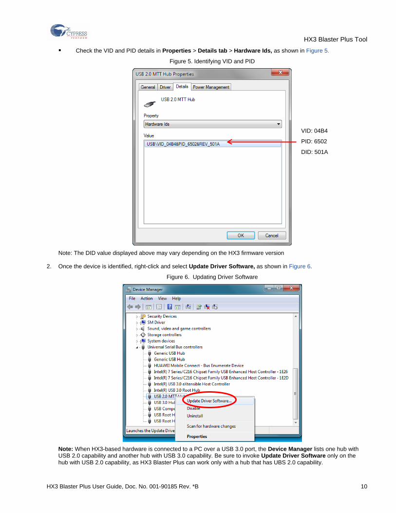
Check the VID and PID details in Properties > Details tab > Hardware Ids, as shown in Figure 5.
Figure 5. Identifying VID and PID
Note: The DID value displayed above may vary depending on the HX3 firmware version
2. Once the device is identified, right-click and select Update Driver Software, as shown in Figure 6.
Figure 6. Updating Driver Software
Note: When HX3-based hardware is connected to a PC over a USB 3.0 port, the Device Manager lists one hub with USB 2.0 capability and another hub with USB 3.0 capability. Be sure to invoke Update Driver Software only on the hub with USB 2.0 capability, as HX3 Blaster Plus can work only with a hub that has UBS 2.0 capability.
VID: 04B4
PID: 6502
DID: 501A
HX3 Blaster Plus Tool
HX3 Blaster Plus User Guide, Doc. No. 001-90185 Rev. *B 11
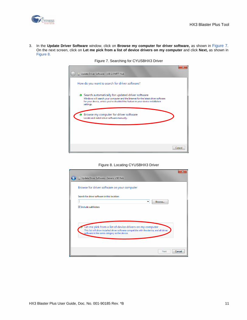
3. In the Update Driver Software window, click on Browse my computer for driver software, as shown in Figure 7. On the next screen, click on Let me pick from a list of device drivers on my computer and click Next, as shown in Figure 8.
Figure 7. Searching for CYUSBHX3 Driver
Figure 8. Locating CYUSBHX3 Driver
HX3 Blaster Plus Tool
HX3 Blaster Plus User Guide, Doc. No. 001-90185 Rev. *B 12
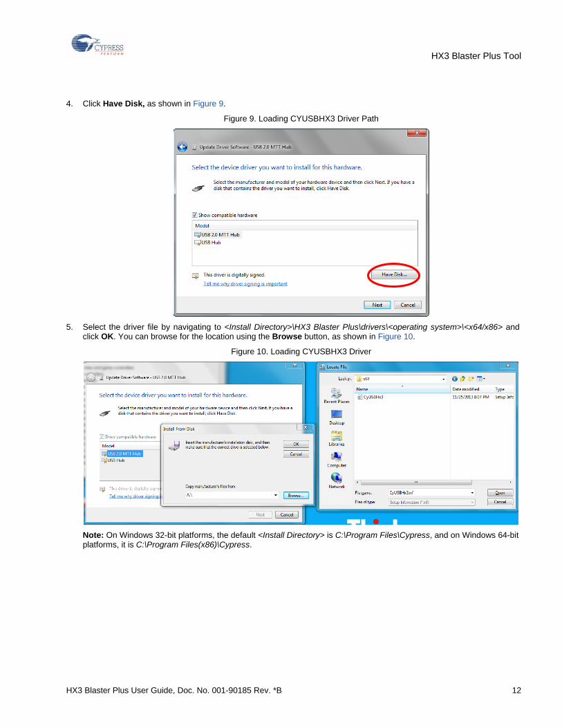
4. Click Have Disk, as shown in Figure 9.
Figure 9. Loading CYUSBHX3 Driver Path
5. Select the driver file by navigating to <Install Directory>\HX3 Blaster Plus\drivers\<operating system>\<x64/x86> and
click OK. You can browse for the location using the Browse button, as shown in Figure 10.
Figure 10. Loading CYUSBHX3 Driver
Note: On Windows 32-bit platforms, the default <Install Directory> is C:\Program Files\Cypress, and on Windows 64-bit platforms, it is C:\Program Files(x86)\Cypress.
HX3 Blaster Plus Tool
HX3 Blaster Plus User Guide, Doc. No. 001-90185 Rev. *B 13
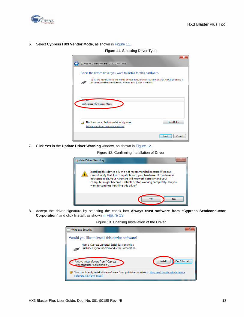
6. Select Cypress HX3 Vendor Mode, as shown in Figure 11.
Figure 11. Selecting Driver Type
7. Click Yes in the Update Driver Warning window, as shown in Figure 12.
Figure 12. Confirming Installation of Driver
8. Accept the driver signature by selecting the check box Always trust software from “Cypress Semiconductor
Corporation” and click Install, as shown in Figure 13.
Figure 13. Enabling Installation of the Driver
HX3 Blaster Plus Tool
HX3 Blaster Plus User Guide, Doc. No. 001-90185 Rev. *B 14
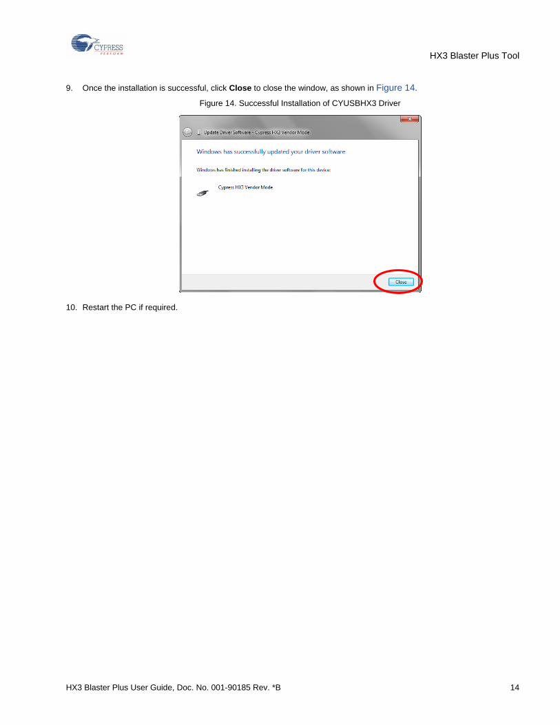
9. Once the installation is successful, click Close to close the window, as shown in Figure 14.
Figure 14. Successful Installation of CYUSBHX3 Driver
10. Restart the PC if required.
HX3 Blaster Plus Tool
HX3 Blaster Plus User Guide, Doc. No. 001-90185 Rev. *B 15
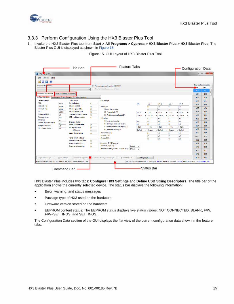
3.3.3 Perform Configuration Using the HX3 Blaster Plus Tool 1. Invoke the HX3 Blaster Plus tool from Start > All Programs > Cypress > HX3 Blaster Plus > HX3 Blaster Plus. The
Blaster Plus GUI is displayed as shown in Figure 15.
Figure 15. GUI Layout of HX3 Blaster Plus Tool
HX3 Blaster Plus includes two tabs: Configure HX3 Settings and Define USB String Descriptors. The title bar of the application shows the currently selected device. The status bar displays the following information:
Error, warning, and status messages
Package type of HX3 used on the hardware
Firmware version stored on the hardware
EEPROM content status: The EEPROM status displays five status values: NOT CONNECTED, BLANK, F/W, F/W+SETTINGS, and SETTINGS.
The Configuration Data section of the GUI displays the flat view of the current configuration data shown in the feature tabs.
Status Bar
Configuration Data Title Bar Feature Tabs
Command Bar
HX3 Blaster Plus Tool
HX3 Blaster Plus User Guide, Doc. No. 001-90185 Rev. *B 16
Table 4 provides an overview of the seven groups of configuration settings supported by the HX3 Blaster Plus tool.
Table 4. Configuration Setting Groups
Configuration Setting Group
Description
General Settings This group of parameters is related to hub descriptor fields that are sent to the host. These controls are per the USB-IF hub specification and change the enumeration details of HX3.
GPIO Control This group controls the default behavior of GPIO pins and Port Status Indicator LED pins. The HX3 Blaster Plus tool gives you an option to drop the Port Status Indicator LEDs to free up the GPIOs.
Charging Control This group consists of configurable parameters related to USB Battery Charging, proprietary charging, and Ghost Charging™.
Power Switch Settings This group consists of configurable parameters related to HX3 power management controls such as Power Enable polarity, overcurrent polarity, and ganged power switching.
Port Settings This group consists of configurable parameters related to port-specific features such as Shared Link™, dedicated charging port (DCP), charging downstream port (CDP), and port polarity swapping. Also the Physical Layer (PHY) parameters for each port can be tuned per the hardware design.
Common HS PHY Settings This group consists of configurable parameters related to advanced, high-speed PHY settings common to all the downstream and upstream ports.
USB String Descriptors This group consists of three configurable string descriptors, including manufacturer string descriptor, product string descriptor, and serial number string descriptor.
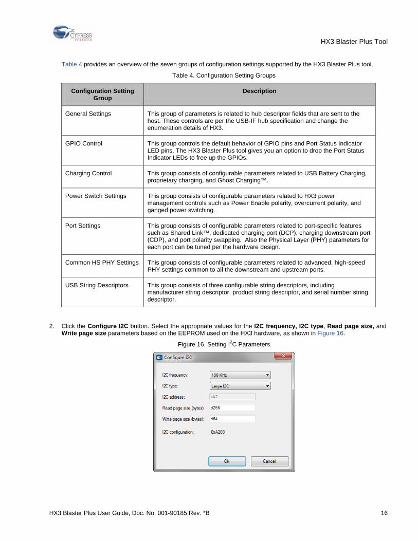
2. Click the Configure I2C button. Select the appropriate values for the I2C frequency, I2C type, Read page size, and Write page size parameters based on the EEPROM used on the HX3 hardware, as shown in Figure 16.
Figure 16. Setting I2C Parameters
HX3 Blaster Plus Tool
HX3 Blaster Plus User Guide, Doc. No. 001-90185 Rev. *B 17
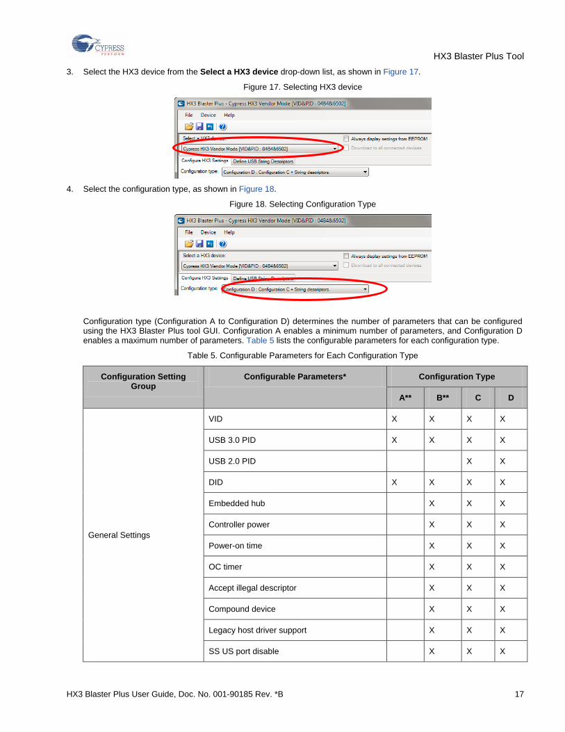
3. Select the HX3 device from the Select a HX3 device drop-down list, as shown in Figure 17.
Figure 17. Selecting HX3 device
4. Select the configuration type, as shown in Figure 18.
Figure 18. Selecting Configuration Type
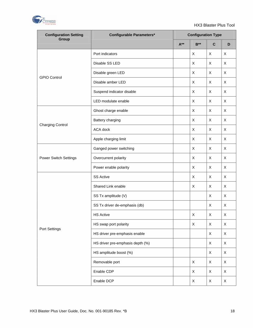
Configuration type (Configuration A to Configuration D) determines the number of parameters that can be configured using the HX3 Blaster Plus tool GUI. Configuration A enables a minimum number of parameters, and Configuration D enables a maximum number of parameters. Table 5 lists the configurable parameters for each configuration type.
Table 5. Configurable Parameters for Each Configuration Type
Configuration Setting Group
Configurable Parameters* Configuration Type
A** B** C D
General Settings
VID X X X X
USB 3.0 PID X X X X
USB 2.0 PID X X
DID X X X X
Embedded hub X X X
Controller power X X X
Power-on time X X X
OC timer X X X
Accept illegal descriptor X X X
Compound device X X X
Legacy host driver support X X X
SS US port disable X X X
HX3 Blaster Plus Tool
HX3 Blaster Plus User Guide, Doc. No. 001-90185 Rev. *B 18
Configuration Setting Group
Configurable Parameters* Configuration Type
A** B** C D
GPIO Control
Port indicators X X X
Disable SS LED X X X
Disable green LED X X X
Disable amber LED X X X
Suspend indicator disable X X X
LED modulate enable X X X
Charging Control
Ghost charge enable X X X
Battery charging X X X
ACA dock X X X
Apple charging limit X X X
Power Switch Settings
Ganged power switching X X X
Overcurrent polarity X X X
Power enable polarity X X X
Port Settings
SS Active X X X
Shared Link enable X X X
SS Tx amplitude (V) X X
SS Tx driver de-emphasis (db) X X
HS Active X X X
HS swap port polarity X X X
HS driver pre-emphasis enable X X
HS driver pre-emphasis depth (%) X X
HS amplitude boost (%) X X
Removable port X X X
Enable CDP X X X
Enable DCP X X X
HX3 Blaster Plus Tool
HX3 Blaster Plus User Guide, Doc. No. 001-90185 Rev. *B 19
Configuration Setting Group
Configurable Parameters* Configuration Type
A** B** C D
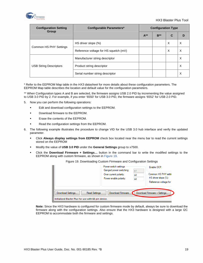
Common HS PHY Settings HS driver slope (%) X X
Reference voltage for HS squelch (mV) X X
USB String Descriptors
Manufacturer string descriptor X
Product string descriptor X
Serial number string descriptor X
* Refer to the EEPROM Map table in the HX3 datasheet for more details about these configuration parameters. The EEPROM Map table describes the location and default value for the configuration parameters.
** When Configuration types A and B are selected, the firmware assigns USB 2.0 PID by incrementing the value assigned to USB 3.0 PID by 2. For example, if you enter ‘6550’ for USB 3.0 PID, the firmware assigns ‘6552’ for USB 2.0 PID.
5. Now you can perform the following operations:
Edit and download configuration settings to the EEPROM.
Download firmware to the EEPROM.
Erase the contents of the EEPROM.
Read the configuration settings from the EEPROM.
6. The following example illustrates the procedure to change VID for the USB 3.0 hub interface and verify the updated parameter.
Click Always display settings from EEPROM check box located near the menu bar to read the current settings stored on the EEPROM
Modify the value of USB 3.0 PID under the General Settings group to x7500.
Click the Download Firmware + Settings… button in the command bar to write the modified settings to the EEPROM along with custom firmware, as shown in Figure 19.
Figure 19. Downloading Custom Firmware and Configuration Settings
Note: Since the HX3 hardware is configured for custom firmware mode by default, always be sure to download the firmware along with the configuration settings. Also ensure that the HX3 hardware is designed with a large I2C EEPROM to accommodate both the firmware and settings.
HX3 Blaster Plus Tool
HX3 Blaster Plus User Guide, Doc. No. 001-90185 Rev. *B 20
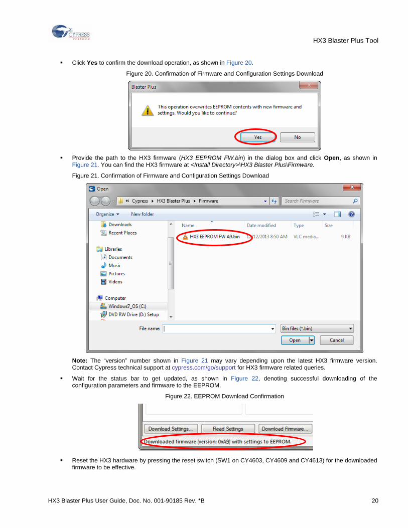
Click Yes to confirm the download operation, as shown in Figure 20.
Figure 20. Confirmation of Firmware and Configuration Settings Download
Provide the path to the HX3 firmware (HX3 EEPROM FW.bin) in the dialog box and click Open, as shown in
Figure 21. You can find the HX3 firmware at <Install Directory>\HX3 Blaster Plus\Firmware.
Figure 21. Confirmation of Firmware and Configuration Settings Download
Note: The “version” number shown in Figure 21 may vary depending upon the latest HX3 firmware version. Contact Cypress technical support at cypress.com/go/support for HX3 firmware related queries.
Wait for the status bar to get updated, as shown in Figure 22, denoting successful downloading of the configuration parameters and firmware to the EEPROM.
Figure 22. EEPROM Download Confirmation
Reset the HX3 hardware by pressing the reset switch (SW1 on CY4603, CY4609 and CY4613) for the downloaded
firmware to be effective.
HX3 Blaster Plus Tool
HX3 Blaster Plus User Guide, Doc. No. 001-90185 Rev. *B 21
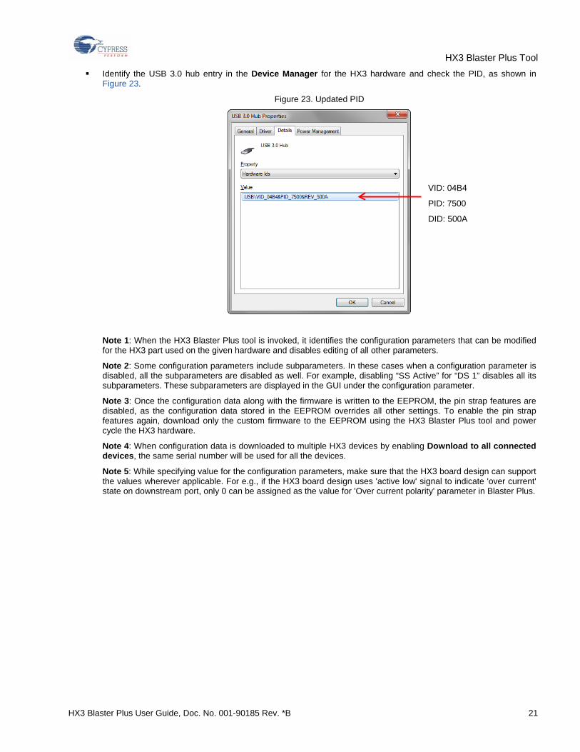
Identify the USB 3.0 hub entry in the Device Manager for the HX3 hardware and check the PID, as shown in Figure 23.
Figure 23. Updated PID
Note 1: When the HX3 Blaster Plus tool is invoked, it identifies the configuration parameters that can be modified for the HX3 part used on the given hardware and disables editing of all other parameters.
Note 2: Some configuration parameters include subparameters. In these cases when a configuration parameter is disabled, all the subparameters are disabled as well. For example, disabling “SS Active” for “DS 1” disables all its subparameters. These subparameters are displayed in the GUI under the configuration parameter.
Note 3: Once the configuration data along with the firmware is written to the EEPROM, the pin strap features are disabled, as the configuration data stored in the EEPROM overrides all other settings. To enable the pin strap features again, download only the custom firmware to the EEPROM using the HX3 Blaster Plus tool and power cycle the HX3 hardware.
Note 4: When configuration data is downloaded to multiple HX3 devices by enabling Download to all connected devices, the same serial number will be used for all the devices.
Note 5: While specifying value for the configuration parameters, make sure that the HX3 board design can support the values wherever applicable. For e.g., if the HX3 board design uses 'active low' signal to indicate 'over current' state on downstream port, only 0 can be assigned as the value for 'Over current polarity' parameter in Blaster Plus.
VID: 04B4
PID: 7500
DID: 500A
HX3 Blaster Plus Tool
HX3 Blaster Plus User Guide, Doc. No. 001-90185 Rev. *B 22
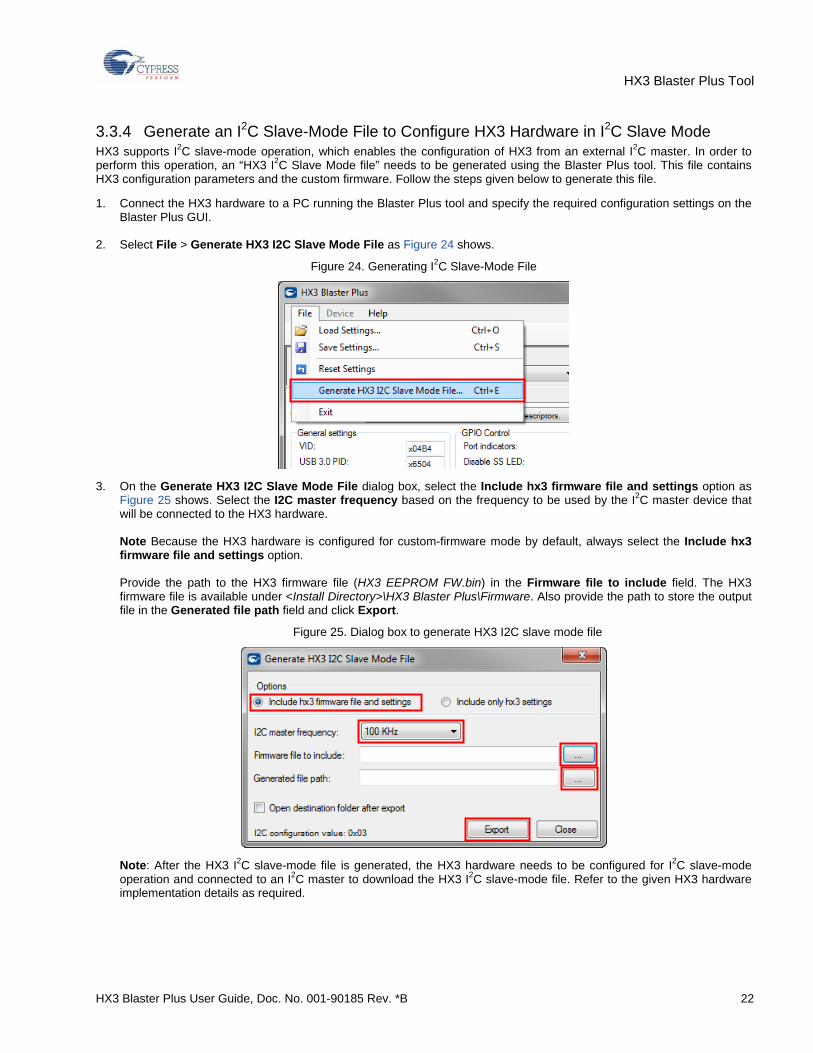
3.3.4 Generate an I2C Slave-Mode File to Configure HX3 Hardware in I2C Slave Mode HX3 supports I2C slave-mode operation, which enables the configuration of HX3 from an external I2C master. In order to perform this operation, an “HX3 I2C Slave Mode file” needs to be generated using the Blaster Plus tool. This file contains HX3 configuration parameters and the custom firmware. Follow the steps given below to generate this file.
1. Connect the HX3 hardware to a PC running the Blaster Plus tool and specify the required configuration settings on the Blaster Plus GUI.
2. Select File > Generate HX3 I2C Slave Mode File as Figure 24 shows.
Figure 24. Generating I2C Slave-Mode File
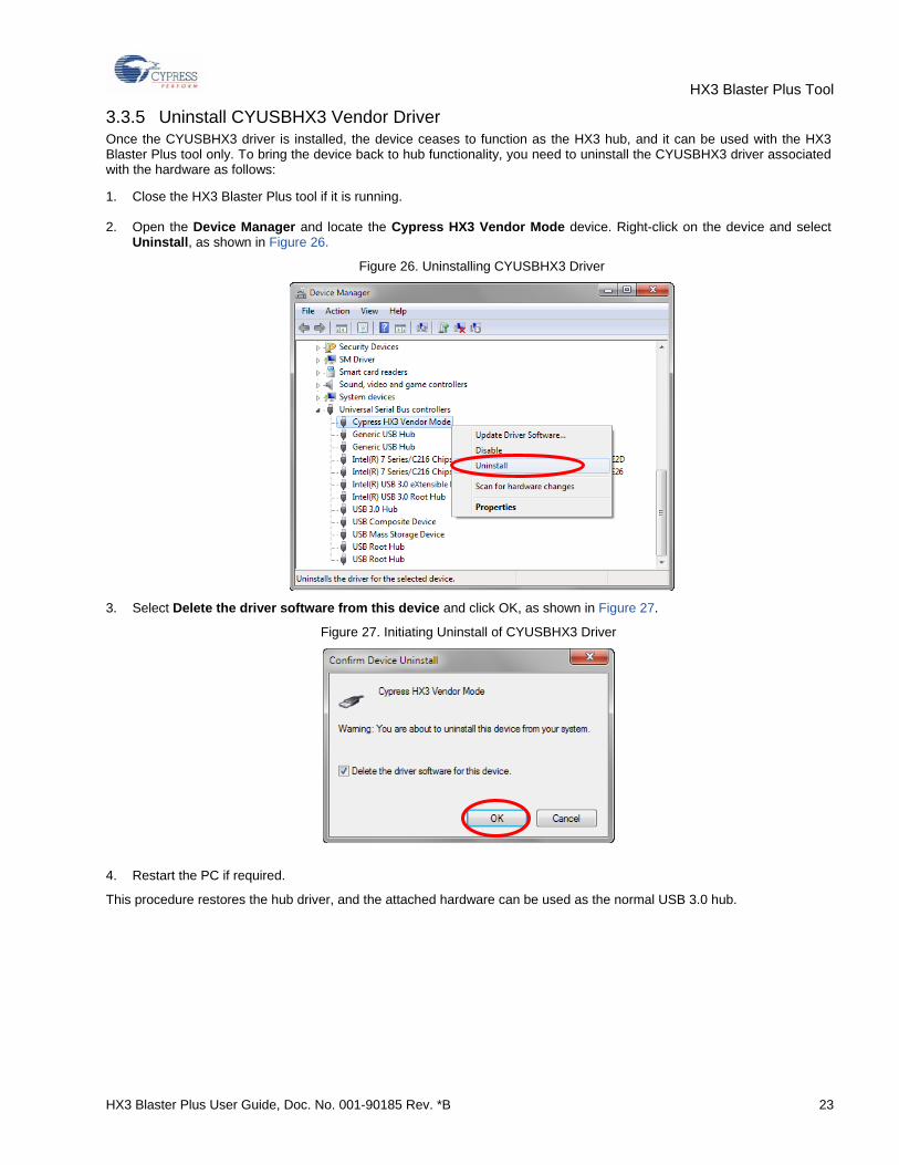
3. On the Generate HX3 I2C Slave Mode File dialog box, select the Include hx3 firmware file and settings option as Figure 25 shows. Select the I2C master frequency based on the frequency to be used by the I2C master device that will be connected to the HX3 hardware. Note Because the HX3 hardware is configured for custom-firmware mode by default, always select the Include hx3 firmware file and settings option. Provide the path to the HX3 firmware file (HX3 EEPROM FW.bin) in the Firmware file to include field. The HX3 firmware file is available under <Install Directory>\HX3 Blaster Plus\Firmware. Also provide the path to store the output file in the Generated file path field and click Export.
Figure 25. Dialog box to generate HX3 I2C slave mode file
Note: After the HX3 I2C slave-mode file is generated, the HX3 hardware needs to be configured for I2C slave-mode operation and connected to an I2C master to download the HX3 I2C slave-mode file. Refer to the given HX3 hardware implementation details as required.
HX3 Blaster Plus Tool
HX3 Blaster Plus User Guide, Doc. No. 001-90185 Rev. *B 23
3.3.5 Uninstall CYUSBHX3 Vendor Driver Once the CYUSBHX3 driver is installed, the device ceases to function as the HX3 hub, and it can be used with the HX3 Blaster Plus tool only. To bring the device back to hub functionality, you need to uninstall the CYUSBHX3 driver associated with the hardware as follows:
1. Close the HX3 Blaster Plus tool if it is running.
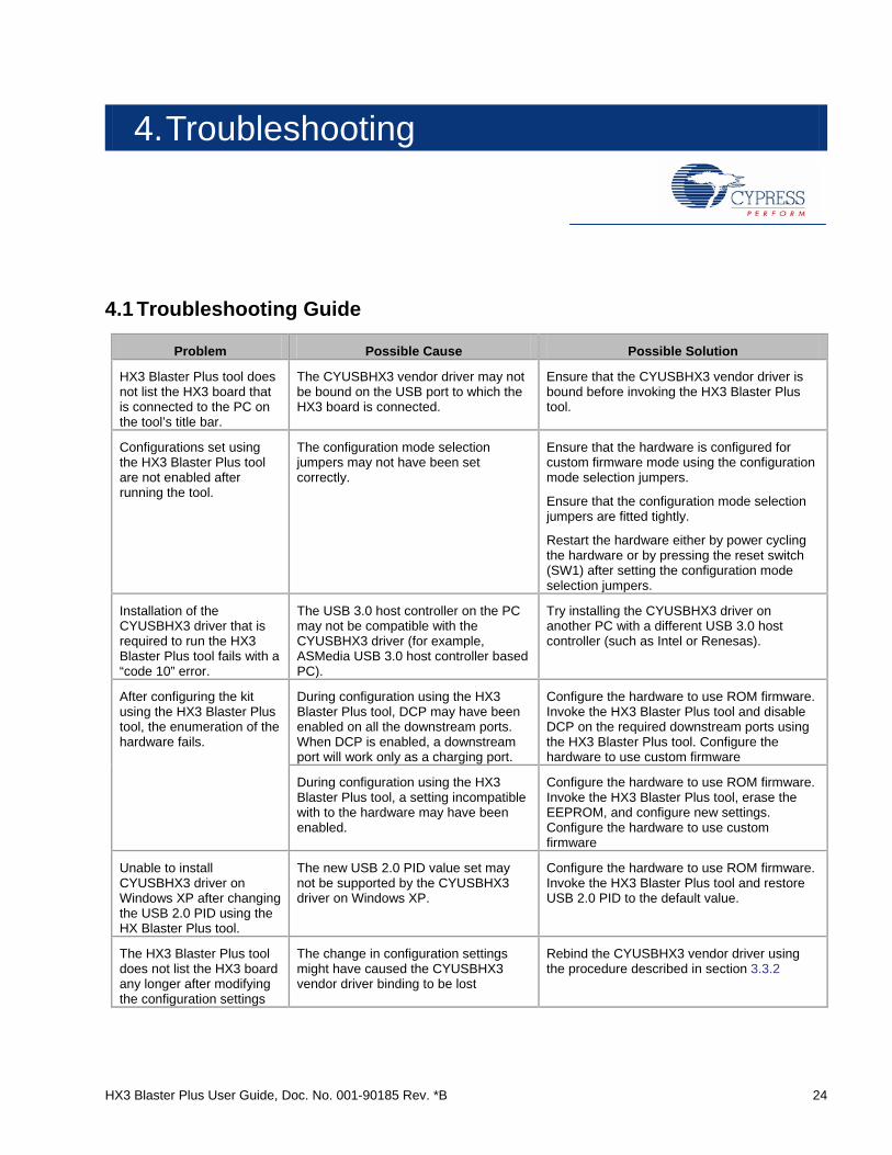
2. Open the Device Manager and locate the Cypress HX3 Vendor Mode device. Right-click on the device and select Uninstall, as shown in Figure 26.
Figure 26. Uninstalling CYUSBHX3 Driver
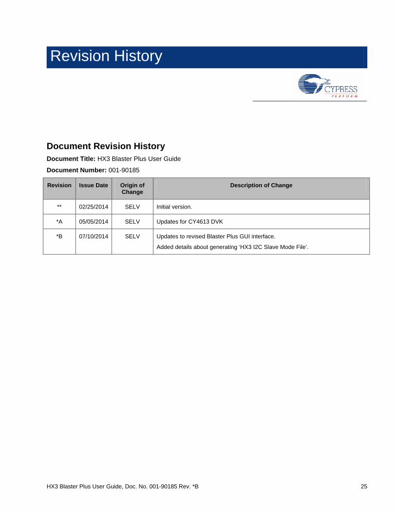
3. Select Delete the driver software from this device and click OK, as shown in Figure 27.
Figure 27. Initiating Uninstall of CYUSBHX3 Driver
4. Restart the PC if required.
This procedure restores the hub driver, and the attached hardware can be used as the normal USB 3.0 hub.
HX3 Blaster Plus User Guide, Doc. No. 001-90185 Rev. *B 24
4. Troubleshooting
4.1 Troubleshooting Guide
Problem Possible Cause Possible Solution
HX3 Blaster Plus tool does not list the HX3 board that is connected to the PC on the tool’s title bar.
The CYUSBHX3 vendor driver may not be bound on the USB port to which the HX3 board is connected.
Ensure that the CYUSBHX3 vendor driver is bound before invoking the HX3 Blaster Plus tool.
Configurations set using the HX3 Blaster Plus tool are not enabled after running the tool.
The configuration mode selection jumpers may not have been set correctly.
Ensure that the hardware is configured for custom firmware mode using the configuration mode selection jumpers.
Ensure that the configuration mode selection jumpers are fitted tightly.
Restart the hardware either by power cycling the hardware or by pressing the reset switch (SW1) after setting the configuration mode selection jumpers.
Installation of the CYUSBHX3 driver that is required to run the HX3 Blaster Plus tool fails with a “code 10” error.
The USB 3.0 host controller on the PC may not be compatible with the CYUSBHX3 driver (for example, ASMedia USB 3.0 host controller based PC).
Try installing the CYUSBHX3 driver on another PC with a different USB 3.0 host controller (such as Intel or Renesas).
After configuring the kit using the HX3 Blaster Plus tool, the enumeration of the hardware fails.
During configuration using the HX3 Blaster Plus tool, DCP may have been enabled on all the downstream ports. When DCP is enabled, a downstream port will work only as a charging port.
Configure the hardware to use ROM firmware. Invoke the HX3 Blaster Plus tool and disable DCP on the required downstream ports using the HX3 Blaster Plus tool. Configure the hardware to use custom firmware
During configuration using the HX3 Blaster Plus tool, a setting incompatible with to the hardware may have been enabled.
Configure the hardware to use ROM firmware. Invoke the HX3 Blaster Plus tool, erase the EEPROM, and configure new settings. Configure the hardware to use custom firmware
Unable to install CYUSBHX3 driver on Windows XP after changing the USB 2.0 PID using the HX Blaster Plus tool.
The new USB 2.0 PID value set may not be supported by the CYUSBHX3 driver on Windows XP.
Configure the hardware to use ROM firmware. Invoke the HX3 Blaster Plus tool and restore USB 2.0 PID to the default value.
The HX3 Blaster Plus tool does not list the HX3 board any longer after modifying the configuration settings
The change in configuration settings might have caused the CYUSBHX3 vendor driver binding to be lost
Rebind the CYUSBHX3 vendor driver using the procedure described in section 3.3.2
HX3 Blaster Plus User Guide, Doc. No. 001-90185 Rev. *B 25
Revision History
Document Revision History Document Title: HX3 Blaster Plus User Guide
Document Number: 001-90185
Revision Issue Date Origin of Change
Description of Change
** 02/25/2014 SELV Initial version.
*A 05/05/2014 SELV Updates for CY4613 DVK
*B 07/10/2014 SELV Updates to revised Blaster Plus GUI interface.
Added details about generating ‘HX3 I2C Slave Mode File’.