Embed Size (px)
Citation preview
SERBIAN JOURNAL OF ELECTRICAL ENGINEERING Vol. 5, No. 1, May 2008, 121-138
121
Hybrid Posicast Controller for a DC-DC Buck Converter
Kaithamalai Udhayakumar1, Ponnusamy Lakshmi2, Kandasamy Boobal2
Abstract: A new Posicast compensated hybrid controller for the DC-DC Buck converter is investigated. Posicast is a feedforward compensator, which eliminates the overshoot in the step response of a lightly damped system. However, the traditional method is sensitive to variations in natural frequency. The new method described here reduces this undesirable sensitivity by using Posicast within the feedback loop. Design of the Posicast function is independent of computational delay. The new controller results in a lower noise in the control signal, when compared to a conventional PID controller.
Keywords: DC-DC Buck converter, Posicast, PID controller.
1 Introduction One of the challenges in controlling the DC-DC converter is compensation
for the converter’s nonlinear damped dynamics which are a function of load parameters [1]. Advances in signal processing technology have spurred research in new control techniques to improve converter control [3]. In this work, a new control technique based on the Posicast principle is employed. Classical Posicast is a feed forward control method for lightly damped systems [2]. It has the potential to eliminate the oscillatory response of a lightly damped system, but the drawback is sensitivity to model uncertainty [1]. The Posicast approach can be more useful if the parametric sensitivity can be reduced. The drawback is eliminated by using the Posicast in a feedback loop; this reduces the sensitivity to parameter variations [5].
Research has shown that PID-based control of the power converter may require additional algorithm modifications to achieve a combination of good transient and steady-state performance [6]. These modifications include the use of a control dead zone, an averaging digital filter to counteract switching noise, and the use of two sets of gains (one set for the transient period and the second set for steady-state performance).The application of PID-type controllers for buck converters is further complicated in a digital implementation. 1Department of Electrical and Electronics Engineering, College of Engineering Guindy, Anna University, Chennai 600 025, India; E-mail: [email protected] 2Department of Electrical and Electronics Engineering, College of Engineering Guindy, Anna University, Chennai 600 025, India.
K. Udhayakumar, P. Lakshmi, K. Boobal
122
The Posicast-based controller described in this work, produces many of the beneficial closed loop effects of the PID-type controller, such as good steady-state performance and good damping of resonant behavior. Controller gain parameters are very easy to determine. The control method produces a very good response that is predictable by the small-signal averaged continuous time model. The key element of the Posicast controller structure is especially easy to implement in discrete-time hardware. The frequency response of the Posicast element inherently reduces high-frequency noise [5], and the damping effect of Posicast eliminates the need for multiple sets of controller gains. The proposed method does not require any of the additional modifications described earlier for PID control (deadzone, additional filtering, gain scheduling). The state space modeling of a converter [8-11] and Small signal Model with parasitic elements is also derived for the converter [3-4].
In summary, a classical Posicast has superior damping qualities, reduced sensitivity to parametric uncertainty and load change through feedback. So, the proposed control method is a significant departure from the classical posicast. The organization of this paper is as follows. Section 2 provides mathematical modeling of a DC-DC buck converter. Section 3 develops the controller design based on the control objectives. In Section 4, the controller modeling is described based on a small signal model of the converter in the transfer function form. Section 5 shows the obtained simulation results of a Posicast compensated DC-DC buck converter for the output voltage, duty cycle and load current for different values of input voltage, load resistances and Posicast parameters. The simulation results for a PID controller are also given for comparison purposes. Finally, some conclusions are drawn.
2 Modeling 2.1 State space analysis
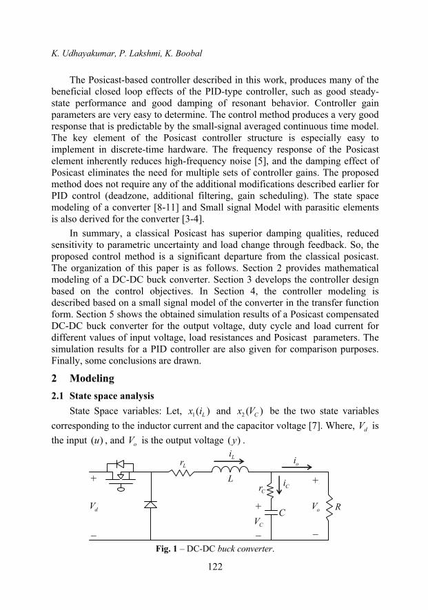
State Space variables: Let, 1( )Lx i and 2 ( )Cx V be the two state variables corresponding to the inductor current and the capacitor voltage [7]. Where, dV is the input ( )u , and oV is the output voltage ( )y .
Fig. 1 – DC-DC buck converter.
Hybrid Posicast Controller for a DC-DC Buck Converter
123
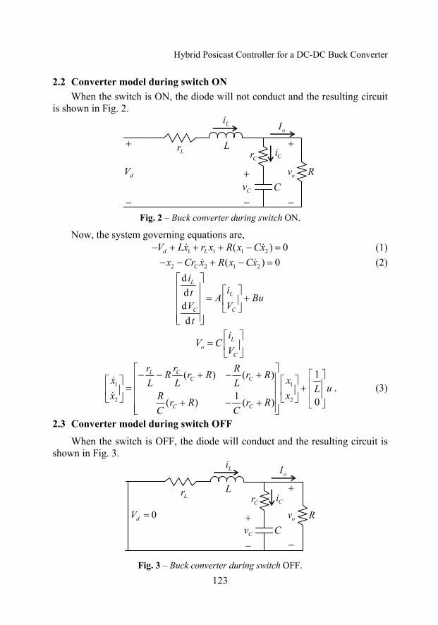
2.2 Converter model during switch ON When the switch is ON, the diode will not conduct and the resulting circuit
is shown in Fig. 2.
Fig. 2 – Buck converter during switch ON.
Now, the system governing equations are, 1 1 1 2( ) 0d LV Lx r x R x Cx− + + + − = (1) 2 2 1 2( ) 0Cx Cr x R x Cx− − + − = (2)
dddd
L
L
C C
iit A Bu
V Vt
⎡ ⎤⎢ ⎥ ⎡ ⎤
= +⎢ ⎥ ⎢ ⎥⎢ ⎥ ⎣ ⎦⎢ ⎥⎣ ⎦
Lo
C
iV C
V⎡ ⎤
= ⎢ ⎥⎣ ⎦
1 1
2 2
1( ) ( )
1 0( ) ( )
CLC C
C C
rr RR r R r Rx xL L L uLx xR r R r R
C C
⎡ ⎤− − + − + ⎡ ⎤⎢ ⎥⎡ ⎤ ⎡ ⎤ ⎢ ⎥= +⎢ ⎥⎢ ⎥ ⎢ ⎥ ⎢ ⎥⎢ ⎥⎣ ⎦ ⎣ ⎦+ − + ⎣ ⎦⎢ ⎥⎣ ⎦
. (3)
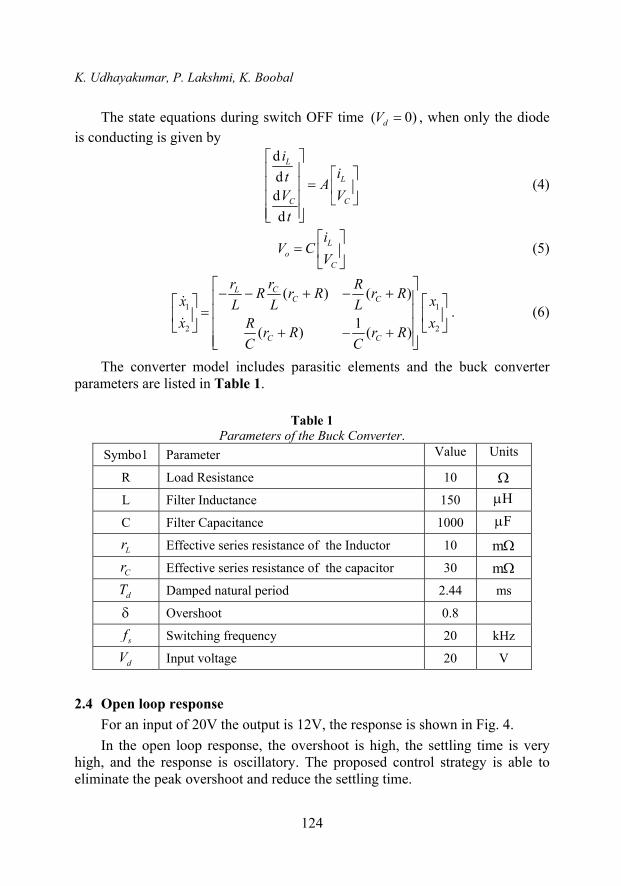
2.3 Converter model during switch OFF
When the switch is OFF, the diode will conduct and the resulting circuit is shown in Fig. 3.
Fig. 3 – Buck converter during switch OFF.
K. Udhayakumar, P. Lakshmi, K. Boobal
124
The state equations during switch OFF time ( 0)dV = , when only the diode is conducting is given by
dddd
L
L
C C
iit A
V Vt
⎡ ⎤⎢ ⎥ ⎡ ⎤
=⎢ ⎥ ⎢ ⎥⎢ ⎥ ⎣ ⎦⎢ ⎥⎣ ⎦
(4)
Lo
C
iV C
V⎡ ⎤
= ⎢ ⎥⎣ ⎦
(5)
1 1
2 2
( ) ( )
1( ) ( )
CLC C
C C
rr RR r R r Rx xL L Lx xR r R r R
C C
⎡ ⎤− − + − +⎢ ⎥⎡ ⎤ ⎡ ⎤= ⎢ ⎥⎢ ⎥ ⎢ ⎥⎢ ⎥⎣ ⎦ ⎣ ⎦+ − +⎢ ⎥⎣ ⎦
. (6)
The converter model includes parasitic elements and the buck converter parameters are listed in Table 1.
Table 1
Parameters of the Buck Converter. Symbo1 Parameter Value Units
R Load Resistance 10 Ω L Filter Inductance 150 Hμ
C Filter Capacitance 1000 Fμ
Lr Effective series resistance of the Inductor 10 mΩ
Cr Effective series resistance of the capacitor 30 mΩ
dT Damped natural period 2.44 ms
δ Overshoot 0.8
sf Switching frequency 20 kHz
dV Input voltage 20 V
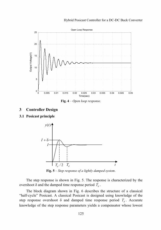
2.4 Open loop response For an input of 20V the output is 12V, the response is shown in Fig. 4. In the open loop response, the overshoot is high, the settling time is very
high, and the response is oscillatory. The proposed control strategy is able to eliminate the peak overshoot and reduce the settling time.
Hybrid Posicast Controller for a DC-DC Buck Converter
125
0 0.005 0.01 0.015 0.02 0.025 0.03 0.035 0.04 0.045 0.050
5
10
15
20
25
Time(sec)
Out
put V
olta
ge(V
)Open Loop Response
Fig. 4 – Open loop response.
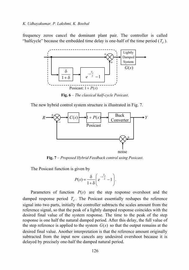
3 Controller Design 3.1 Posicast principle
Fig. 5 – Step response of a lightly damped system.
The step response is shown in Fig. 5. The response is characterized by the overshoot δ and the damped time response period dT .
The block diagram shown in Fig. 6 describes the structure of a classical “half-cycle” Posicast. A classical Posicast is designed using knowledge of the step response overshoot δ and damped time response period dT . Accurate knowledge of the step response parameters yields a compensator whose lowest
K. Udhayakumar, P. Lakshmi, K. Boobal
126
frequency zeros cancel the dominant plant pair. The controller is called “halfcycle” because the embedded time delay is one-half of the time period ( dT ).
Fig. 6 – The classical half-cycle Posicast.
The new hybrid control system structure is illustrated in Fig. 7.
Fig. 7 – Proposed Hybrid Feedback control using Posicast.
The Posicast function is given by
2( ) 11
dTs
P s e−⎛ ⎞δ
= −⎜ ⎟+ δ ⎝ ⎠
.
Parameters of function ( )P s are the step response overshoot and the damped response period dT . The Posicast essentially reshapes the reference signal into two parts, initially the controller subtracts the scales amount from the reference signal, so that the peak of a lightly damped response coincides with the desired final value of the system response. The time to the peak of the step response is one half the natural damped period. After this delay, the full value of the step reference is applied to the system ( )G s so that the output remains at the desired final value. Another interpretation is that the reference amount originally subtracted from the input now cancels any undesired overshoot because it is delayed by precisely one-half the damped natural period.
Hybrid Posicast Controller for a DC-DC Buck Converter
127
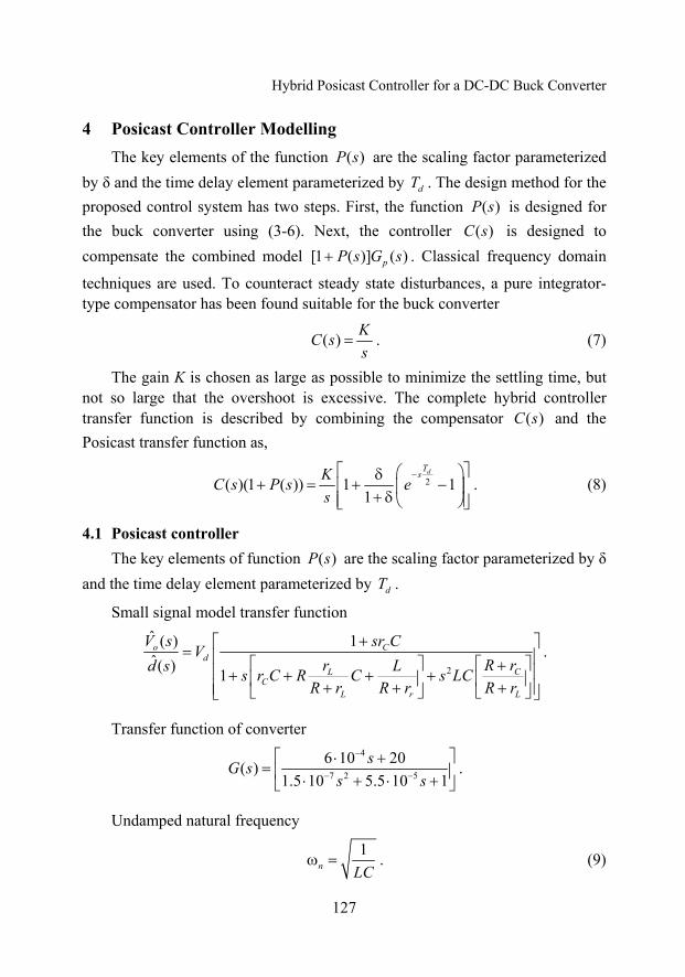
4 Posicast Controller Modelling The key elements of the function ( )P s are the scaling factor parameterized
by δ and the time delay element parameterized by dT . The design method for the proposed control system has two steps. First, the function ( )P s is designed for the buck converter using (3-6). Next, the controller ( )C s is designed to compensate the combined model [1 ( )] ( )pP s G s+ . Classical frequency domain
techniques are used. To counteract steady state disturbances, a pure integrator-type compensator has been found suitable for the buck converter
( ) KC ss
= . (7)
The gain K is chosen as large as possible to minimize the settling time, but not so large that the overshoot is excessive. The complete hybrid controller transfer function is described by combining the compensator ( )C s and the Posicast transfer function as,
2( )(1 ( )) 1 11
dTsKC s P s e
s−⎡ ⎤⎛ ⎞δ
+ = + −⎢ ⎥⎜ ⎟+ δ⎢ ⎥⎝ ⎠⎣ ⎦
. (8)
4.1 Posicast controller The key elements of function ( )P s are the scaling factor parameterized by δ
and the time delay element parameterized by dT .
Small signal model transfer function
2
ˆ ( ) 1ˆ( ) 1
o Cd
CLC
L r L
V s sr CVR rr Ld s s r C R C s LC
R r R r R r
+⎡ ⎤= ⎢ ⎥⎡ ⎤ ⎡ ⎤+⎢ ⎥+ + + +⎢ ⎥ ⎢ ⎥+ + +⎢ ⎥⎣ ⎦ ⎣ ⎦⎣ ⎦
.
Transfer function of converter
4
7 2 5
6 10 20( )1.5 10 5.5 10 1
sG ss s
−
− −
⎡ ⎤⋅ += ⎢ ⎥⋅ + ⋅ +⎣ ⎦
.
Undamped natural frequency
1n LC
ω = . (9)
K. Udhayakumar, P. Lakshmi, K. Boobal
128
Damped time response period
2
21
d
n
T π=ω − ζ
. (10)
Overshoot
21e
ζπ−
−ζδ = . (11) Controller parameters are given below
2.44ms, 0.8dT = δ = .
The gain K is chosen as large as possible to minimize the settling time, but not so large that the overshoot is excessive and it is chosen to be 35.
The resulting transfer function of the hybrid controller is
1.2235( )(1 ( )) 1 0.455( 1)sC s P s es
−⎡ ⎤+ = + −⎣ ⎦ . (12)
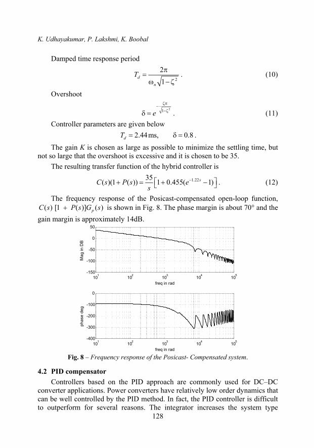
The frequency response of the Posicast-compensated open-loop function, ( ) [1 ( )] ( )pC s P s G s+ is shown in Fig. 8. The phase margin is about 70° and the
gain margin is approximately 14dB.
101 102 103 104 105-150
-100
-50
0
50
freq in rad
Mag
in D
B
101 102 103 104 105-400
-300
-200
-100
0
freq in rad
phas
e de
g
Fig. 8 – Frequency response of the Posicast- Compensated system.
4.2 PID compensator Controllers based on the PID approach are commonly used for DC–DC
converter applications. Power converters have relatively low order dynamics that can be well controlled by the PID method. In fact, the PID controller is difficult to outperform for several reasons. The integrator increases the system type
Hybrid Posicast Controller for a DC-DC Buck Converter
129
number, thus minimizing the steady-state error. Two zeros in the controller enable dampening of resonant characteristics and improving of the transient response. Compared to many other control philosophies, the PID controller structure is fairly easy to explain and understand.
Yet, there are some limitations for PID controllers. The integrator introduces additional phase delay and tends to slow the system response. The phase delay can be countered, however, by the two zeros of the PID controller. A minimum of three gain parameters must be designed for controllers of the PID variety. Two parameters determine the compensators’ zero characteristics, and the third parameter is used to adjust the overall loop gain. One approach for tuning is to use the two zeros to cancel undesirable lightly damped poles in the converter model. The basic PID transfer function is not strictly proper, however, and amplification of high-frequency noise is a serious drawback in switching converter applications.
Practical applications of the PID controller include one or more additional “instrumentation” poles to reduce the high frequency gain. As such, typical PID compensators have four to five gain coefficients to design. The pure integrator in the PID controller also develops problems if the control signal becomes saturated. This is the well-known integrator windup problem; many practical controllers substitute a lag compensator for the pure integrator. Alternatively, some steps to minimize windup effects must be designed and implemented.
101 102 103 104 105-20
0
20
40
60
freq in rad
Mag
in D
B
101 102 103 104 105-400
-300
-200
-100
0
freq in rad
phas
e de
g
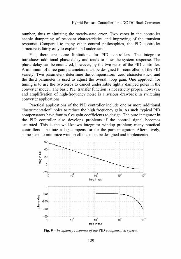
Fig. 9 – Frequency response of the PID compensated system.
K. Udhayakumar, P. Lakshmi, K. Boobal
130
The PID compensator is designed for the buck converter for comparison; the frequency response of the PID-compensated open-loop function is shown in Fig. 9.
5384.62( ) 2.21144 5.7808 10cG s ss
−= + + ⋅ . (13)
4.3 Comparison with PID control Comparing the proposed Posicast-based control to classical PID control
yields useful insights. For the same phase margin, however, the Posicast-compensated magnitude response is significantly suppressed at higher frequencies compared to that of the PID-compensated system. Therefore, the Posicast-compensated system suppresses high frequency noise much better than the PID approach. For identical phase margins, the Posicast-compensated approach yields a larger gain margin.
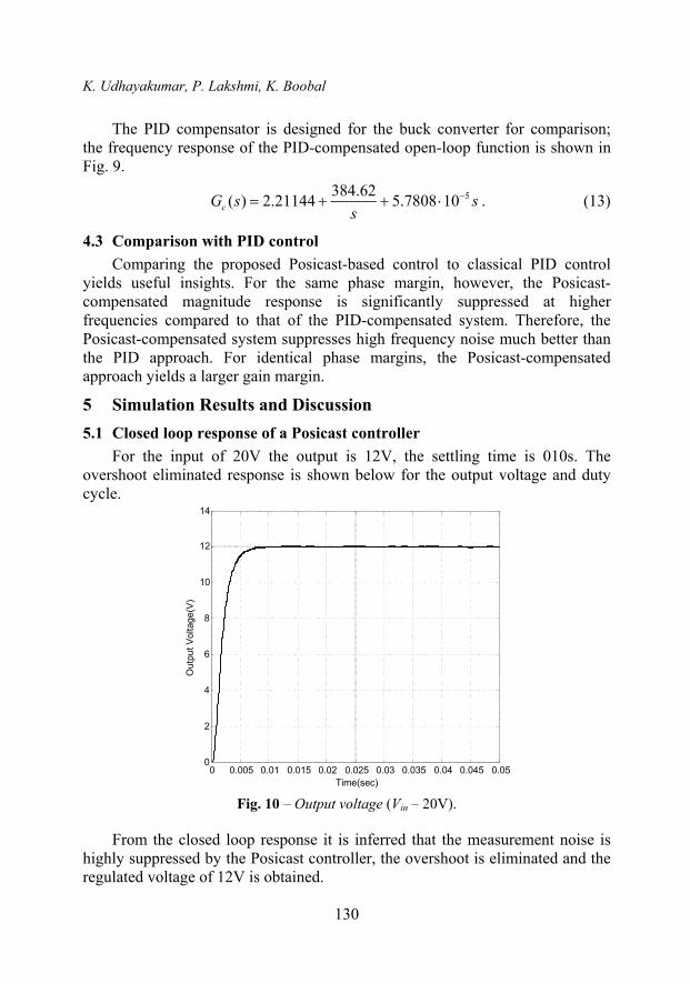
5 Simulation Results and Discussion 5.1 Closed loop response of a Posicast controller
For the input of 20V the output is 12V, the settling time is 010s. The overshoot eliminated response is shown below for the output voltage and duty cycle.
0 0.005 0.01 0.015 0.02 0.025 0.03 0.035 0.04 0.045 0.050
2
4
6
8
10
12
14
Time(sec)
Out
put V
olta
ge(V
)
Fig. 10 – Output voltage (Vin – 20V).
From the closed loop response it is inferred that the measurement noise is highly suppressed by the Posicast controller, the overshoot is eliminated and the regulated voltage of 12V is obtained.
Hybrid Posicast Controller for a DC-DC Buck Converter
131
0 0.005 0.01 0.015 0.02 0.025 0.03 0.035 0.04 0.045 0.050
0.1
0.2
0.3
0.4
0.5
0.6
0.7
Time(sec)
Dut
y C
ycle
Duty Cycle
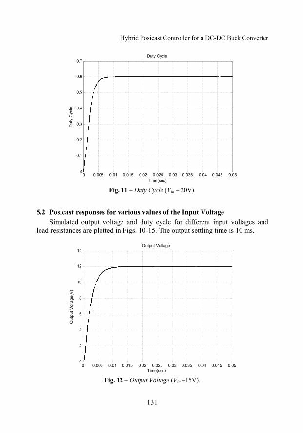
Fig. 11 – Duty Cycle (Vin – 20V).
5.2 Posicast responses for various values of the Input Voltage Simulated output voltage and duty cycle for different input voltages and
load resistances are plotted in Figs. 10-15. The output settling time is 10 ms.
0 0.005 0.01 0.015 0.02 0.025 0.03 0.035 0.04 0.045 0.050
2
4
6
8
10
12
14
Time(sec)
Out
put V
olta
ge(V
)
Output Voltage
Fig. 12 – Output Voltage (Vin –15V).
K. Udhayakumar, P. Lakshmi, K. Boobal
132
0 0.005 0.01 0.015 0.02 0.025 0.03 0.035 0.04 0.045 0.050
0.1
0.2
0.3
0.4
0.5
0.6
0.7
0.8
0.9
Time(sec)
Dut
y C
ycle
Duty Cycle
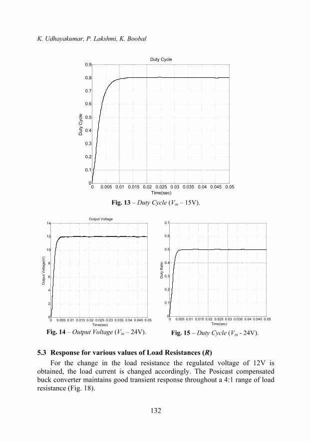
Fig. 13 – Duty Cycle (Vin – 15V).
0 0.005 0.01 0.015 0.02 0.025 0.03 0.035 0.04 0.045 0.050
2
4
6
8
10
12
14
Time(sec)
Out
put V
olta
ge(V
)
Output Voltage
Fig. 14 – Output Voltage (Vin – 24V).
0 0.005 0.01 0.015 0.02 0.025 0.03 0.035 0.04 0.045 0.050
0.1
0.2
0.3
0.4
0.5
0.6
0.7
Time(sec)
Dut
y R
atio
Fig. 15 – Duty Cycle (Vin - 24V).
5.3 Response for various values of Load Resistances (R) For the change in the load resistance the regulated voltage of 12V is
obtained, the load current is changed accordingly. The Posicast compensated buck converter maintains good transient response throughout a 4:1 range of load resistance (Fig. 18).
Hybrid Posicast Controller for a DC-DC Buck Converter
133
0 0.005 0.01 0.015 0.02 0.025 0.03 0.035 0.04 0.045 0.050
2
4
6
8
10
12
14
Time(sec)
Out
put V
olta
ge
Output Voltage
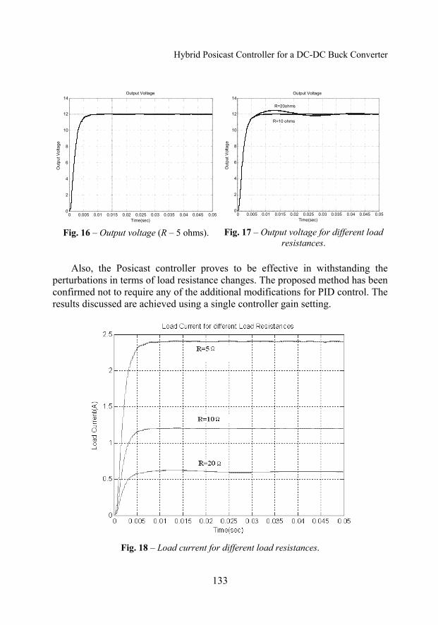
Fig. 16 – Output voltage (R – 5 ohms).
0 0.005 0.01 0.015 0.02 0.025 0.03 0.035 0.04 0.045 0.050
2
4
6
8
10
12
14
Time(sec)O
utpu
t Vol
tage
Output Voltage
R=20ohms
R=10 ohms
Fig. 17 – Output voltage for different load
resistances.
Also, the Posicast controller proves to be effective in withstanding the perturbations in terms of load resistance changes. The proposed method has been confirmed not to require any of the additional modifications for PID control. The results discussed are achieved using a single controller gain setting.
Fig. 18 – Load current for different load resistances.
K. Udhayakumar, P. Lakshmi, K. Boobal
134
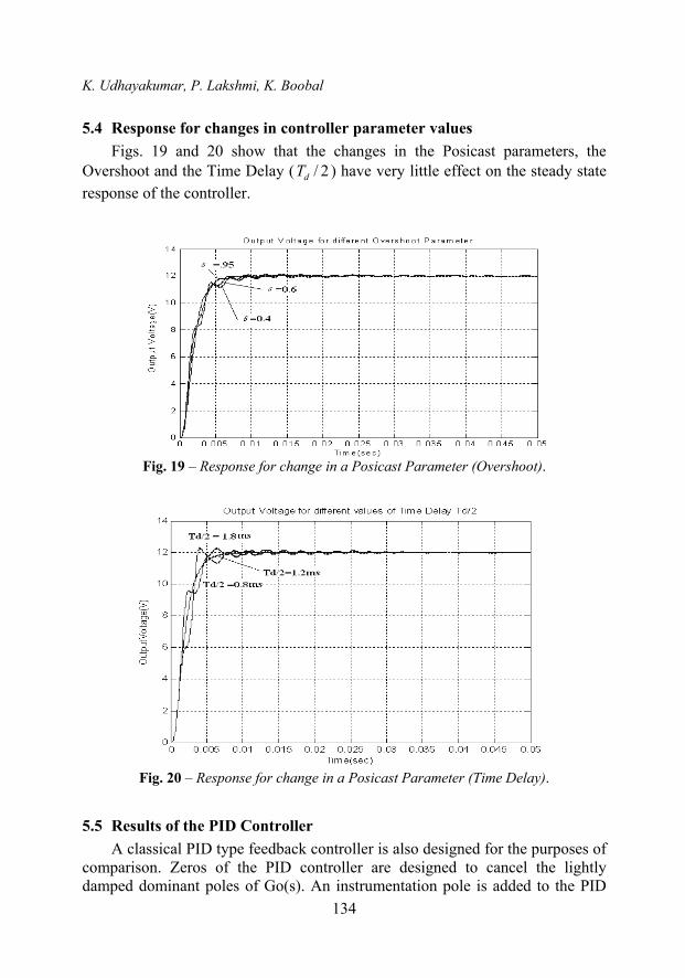
5.4 Response for changes in controller parameter values Figs. 19 and 20 show that the changes in the Posicast parameters, the
Overshoot and the Time Delay ( / 2dT ) have very little effect on the steady state response of the controller.
Fig. 19 – Response for change in a Posicast Parameter (Overshoot).
Fig. 20 – Response for change in a Posicast Parameter (Time Delay).
5.5 Results of the PID Controller A classical PID type feedback controller is also designed for the purposes of
comparison. Zeros of the PID controller are designed to cancel the lightly damped dominant poles of Go(s). An instrumentation pole is added to the PID
Hybrid Posicast Controller for a DC-DC Buck Converter
135
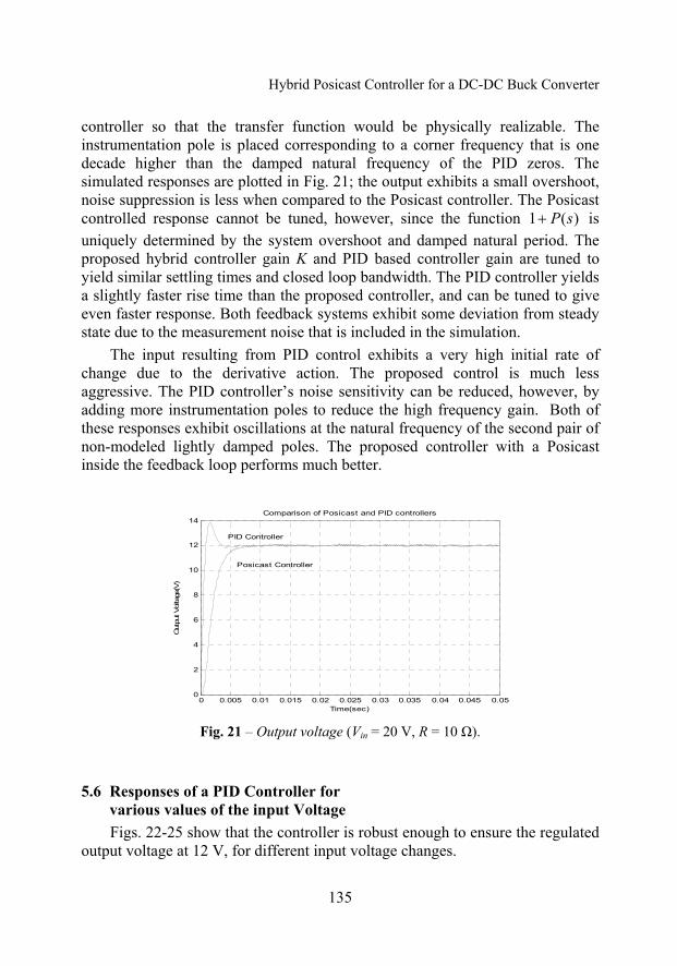
controller so that the transfer function would be physically realizable. The instrumentation pole is placed corresponding to a corner frequency that is one decade higher than the damped natural frequency of the PID zeros. The simulated responses are plotted in Fig. 21; the output exhibits a small overshoot, noise suppression is less when compared to the Posicast controller. The Posicast controlled response cannot be tuned, however, since the function 1 ( )P s+ is uniquely determined by the system overshoot and damped natural period. The proposed hybrid controller gain K and PID based controller gain are tuned to yield similar settling times and closed loop bandwidth. The PID controller yields a slightly faster rise time than the proposed controller, and can be tuned to give even faster response. Both feedback systems exhibit some deviation from steady state due to the measurement noise that is included in the simulation.
The input resulting from PID control exhibits a very high initial rate of change due to the derivative action. The proposed control is much less aggressive. The PID controller’s noise sensitivity can be reduced, however, by adding more instrumentation poles to reduce the high frequency gain. Both of these responses exhibit oscillations at the natural frequency of the second pair of non-modeled lightly damped poles. The proposed controller with a Posicast inside the feedback loop performs much better.
0 0.005 0.01 0.015 0.02 0.025 0.03 0.035 0.04 0.045 0.050
2
4
6
8
10
12
14
Time(sec)
Out
put V
olta
ge(V
)
Comparison of Posicast and PID controllers
PID Controller
Posicast Controller
Fig. 21 – Output voltage (Vin = 20 V, R = 10 Ω).
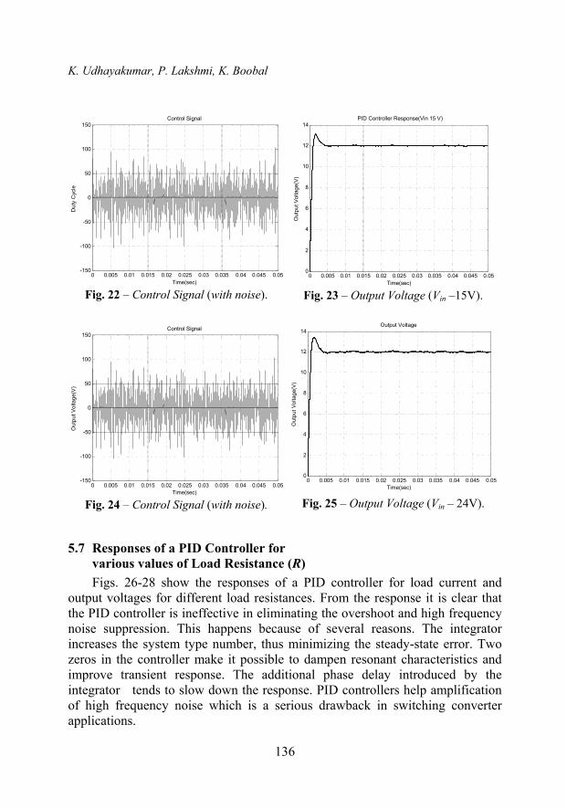
5.6 Responses of a PID Controller for various values of the input Voltage Figs. 22-25 show that the controller is robust enough to ensure the regulated
output voltage at 12 V, for different input voltage changes.
K. Udhayakumar, P. Lakshmi, K. Boobal
136
0 0.005 0.01 0.015 0.02 0.025 0.03 0.035 0.04 0.045 0.05-150
-100
-50
0
50
100
150
Time(sec)
Dut
y C
ycle
Control Signal
Fig. 22 – Control Signal (with noise).
0 0.005 0.01 0.015 0.02 0.025 0.03 0.035 0.04 0.045 0.050
2
4
6
8
10
12
14
Time(sec)
Out
put V
olta
ge(V
)
PID Controller Response(Vin 15 V)
Fig. 23 – Output Voltage (Vin –15V).
0 0.005 0.01 0.015 0.02 0.025 0.03 0.035 0.04 0.045 0.05-150
-100
-50
0
50
100
150
Time(sec)
Out
put V
olta
ge(V
)
Control Signal
Fig. 24 – Control Signal (with noise).
0 0.005 0.01 0.015 0.02 0.025 0.03 0.035 0.04 0.045 0.050
2
4
6
8
10
12
14
Time(sec)
Out
put V
olta
ge(V
)
Output Voltage
Fig. 25 – Output Voltage (Vin – 24V).
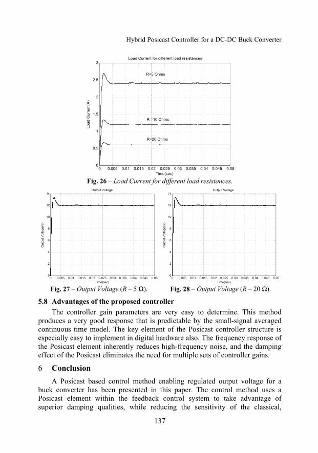
5.7 Responses of a PID Controller for various values of Load Resistance (R) Figs. 26-28 show the responses of a PID controller for load current and
output voltages for different load resistances. From the response it is clear that the PID controller is ineffective in eliminating the overshoot and high frequency noise suppression. This happens because of several reasons. The integrator increases the system type number, thus minimizing the steady-state error. Two zeros in the controller make it possible to dampen resonant characteristics and improve transient response. The additional phase delay introduced by the integrator tends to slow down the response. PID controllers help amplification of high frequency noise which is a serious drawback in switching converter applications.
Hybrid Posicast Controller for a DC-DC Buck Converter
137
0 0.005 0.01 0.015 0.02 0.025 0.03 0.035 0.04 0.045 0.050
0.5
1
1.5
2
2.5
3Load Current for different load resistances
Time(sec)
Load
Cur
rent
(A)
R=5 Ohms
R =10 Ohms
R=20 Ohms
Fig. 26 – Load Current for different load resistances.
0 0.005 0.01 0.015 0.02 0.025 0.03 0.035 0.04 0.045 0.050
2
4
6
8
10
12
14
Time(sec)
Out
put V
olta
ge(V
)
Output Voltage
Fig. 27 – Output Voltage (R – 5 Ω).
0 0.005 0.01 0.015 0.02 0.025 0.03 0.035 0.04 0.045 0.050
2
4
6
8
10
12
14
Time(sec)
Out
put V
olta
ge(V
)
Output Voltage
Fig. 28 – Output Voltage (R – 20 Ω).
5.8 Advantages of the proposed controller The controller gain parameters are very easy to determine. This method
produces a very good response that is predictable by the small-signal averaged continuous time model. The key element of the Posicast controller structure is especially easy to implement in digital hardware also. The frequency response of the Posicast element inherently reduces high-frequency noise, and the damping effect of the Posicast eliminates the need for multiple sets of controller gains.
6 Conclusion A Posicast based control method enabling regulated output voltage for a
buck converter has been presented in this paper. The control method uses a Posicast element within the feedback control system to take advantage of superior damping qualities, while reducing the sensitivity of the classical,
K. Udhayakumar, P. Lakshmi, K. Boobal
138
feedforward Posicast. Posicast element parameters dT and δ can be directly computed from the analytical, ideal method of DC-DC converters. Different variations of a classical Posicast were originally used in a feed forward manner, by reshaping the system input to minimize the oscillatory behaviour of the lightly damped system that followed the Posicast.
The peak overshoot is eliminated and the settling time is much lower with the new control strategy. The measurement noise is highly suppressed and is much better than the PID controller since it has a lower gain at a higher cross over frequency. An integral compensator with a single gain K is used with the Posicast element to ensure the proper steady state response. In contrast to the PID controller, the proposed method only needs to tune the gain K, and the compensated system has improved the gain margin and phase margin and, its narrow open loop bandwidth ensures suppression of high frequency noise. The effect of the lightly damped poles of the buck converter model in the closed loop response is cancelled by the Posicast function. Controller parameters are easy to determine. With the proposed new control strategy the parametric and the load sensitivity is much reduced. In summary, the results obtained indicate that the hybrid Posicast-based controller is an effective approach for DC-DC converter output voltage regulation.
7 References [1] O.J.M. Smith: Posicast Control of Damped Oscillatory Systems, Proc. IRE, Vol. 45, No. 9,
1957, pp. 1249-1255. [2] G. Cook: An Application of Half-cycle Posicast, IEEE Trans. Autom. Control, Vol. AC-11,
No. 3, July 1966, pp. 556-559, [3] R.P. Severns, G.E. Bloom: Modern DC-to-DC Switchmode Power Converter Circuits. New
York: Van Nostrand Reinhold, 1985. [4] N. Mohan , T.M. Undeland,W.P. Robbins: Power Electronics: Converters, Applications and
Design, New York, John Wiley & Sons, Inc., 1995. [5] J.Y. Hung: Feedback Control with Posicast, IEEE Trans. Ind. Electron., Vol. 50, No. 1, 2003,
pp. 94-99. [6] L. Guo , J.Y. Hung, R.M. Nelms: PID Controller Modifications to Improve Steady-State
Performance of Digital Controllers for Buck and Boost Converters, in Proc. 17th Annu. IEEE Appl. Power Electron. Conf. Expo., Dallas, TX, Feb. 2002, pp. 381-388.
[7] M.H. Rashid: Power Electronics Handbook, Academic Press Series in Engineering, 2004. [8] C.T. Rim, G.B. Joung, G.H. Cho: A State Space Modeling of Non-ideal DC-DC Converters,
IEEE Power Electronics Specialists Conf. Rec., 1988, pp. 943-950. [9] R.D. Middlebrook, S. Cuk: A General Unified Approach to Modeling Switching Converter
Stages, IEEE Power Electronics Specialists Conf. Rec., 1976, pp. 18-34. [10] P. Wood: General Theory of Switching Power Converters, IEEE Power Electronics Special-
ists Conf. Rec., 1979, pp. 3-10. [11] V.F. Pires, J.F.A. Silva: Teaching Nonlinear Modeling, Simulation, and Control of Electronic
Power Converters Using MATLAB/SIMULINK, IEEE Trans. Education, Vol. 45, No. 3, Aug. 2002, pp. 253-257.