Embed Size (px)
Citation preview
TC Series Hydraulic Brake ABS System
030.1-1
TC Series Hydraulic Brake ABS System
Blue Bird Corporation assumes sole responsibilityfor ensuring that the information provided herein isaccurate to the best of its knowledge at the time ofprinting. In keeping with its policy of continualproduct improvement, Blue Bird reserves the right tochange product information without notice andwithout incurring obligation. Some informationcontained in this section has been re-published fromthe following publications:
Eaton® Axle & Brake Service Manual, EB & ESModels, Publication number BRSM-0033: April1997. © Eaton Corporation, 1997. All rightsreserved.
Webb® Wheel Products, Inc. Installation, Serviceand Safety Instructions Manual, Publication numberIM-298 (Supercedes IM-494).
Webb® Wheel Products, Inc. Torque Specifications,Publication number SD-012: Revised April, 1997.
Multiple loose-leaf instruction pages provided byCrewson Brunner®, Inc. on installing andmaintaining Automatic Slack Adjusters, nopublication number.
Holset® Air Compressor Field Service Manual, nopublication number or date.
MGM Brakes Model TR – Tamper Resistant SpringBrakes, © MGM 12/92, Form Number 5026-MGM.
Midland™ EL1300 & EL1600 Air CompressorService Procedures, Publication Number L30002,Rev. 9-93, © Midland-Grau Heavy Duty Systems.
Allied Signal Bendix® Brakes Air Brake Handbook,Components, Maintenance and Troubleshooting, ©AlliedSignal T.B.S. Co. 9/1996, Publication numberBW5057.
Allied Signal Bendix® Brakes TU-FLO 550Compressor Service Data SD-01-333, ©AlliedSignal 4/1996, Publication number BW1639.
Allied Signal Bendix® Brakes WS-20 AntilockWheel Speed Sensor Service Data SD-13-4754, ©AlliedSignal T.B.S. Co. 11/1996, Publicationnumber BW1662.
Allied Signal Bendix®
Brakes M-21 and M-22 Antilock ModulatorAssembly Service Data SD-13-4793, © AlliedSignalT.B.S. Co. 11/1996, Publication number BW1664.
Allied Signal Bendix® Brakes EC-17 AntilockTraction Controller Service Data SD-13-4788, ©AlliedSignal T.B.S. Co. 2/1998, Publication numberBW1910.
Allied Signal Bendix® Brakes AD-9 Air DryerService Data SD-08-2412, © AlliedSignal T.B.S.Co. 5/1996, Publication number BW1627.
Allied Signal Bendix® Brakes Push-Pull TypeControl Valves Service Data SD-03-3611, ©AlliedSignal T.B.S. Co. 4/1996, Publication numberBW1578.
Allied Signal Bendix® Brakes E-6 & E-10 DualBrake Valves Service Data SD-03-817, ©AlliedSignal 6/1996, Publication number BW1427.
Allied Signal Bendix® Brakes R-12 & R-14 RelayValves Service Data SD-03-1064, © AlliedSignal6/1996, Publication number BW1431.
TC Series Hydraulic Brake ABS System
030.1-2
Table of Contents
Table of Contents .......................................... 2Safety.............................................................. 3Warnings and Cautions................................ 3Introduction................................................... 3Description of Operation.............................. 3Electronic Control Unit (ECU)Identification ................................................. 4System Components...................................... 5Component Removal and Installation ........ 7Wheel Speed Sensor Replacement – FrontAxle................................................................. 7Modulator Assembly Installation ................ 8Hydraulic ABS System Brake BleedingProcedure....................................................... 9Manual Bleeding ........................................... 10Troubleshooting and Testing ....................... 10Testing the System ........................................ 18
List of FiguresFigure 1—Version C and D ECU ................... 4Figure 1.2—A Typical Meritor WABCO
Hydraulic ABS System .............................. 4Figure 1.3—Electronic Control Unit .............. 5Figure 1.4—Modulator Assembly .................. 5Figure 1.5—Sensor with Molded Socket........ 5Figure 1.6—Sensor Spring Clip...................... 6Figure 1.7—Tooth Wheel ............................... 6Figure 1.8—Sensor Extension Cables ............ 6Figure 1.9—ABS Indicator............................. 6Figure 2—Knuckle Mounted Sensor .............. 7Figure 2.1—Bundle Excess Cable .................. 7Figure 2.2—Modulator Position ..................... 8Figure 2.3—Rear Bleeding Location.............. 10Figure 2.4—Front Bleeding Location............. 10Figure 3—Pin Numbers and Location ............ 11
List of TablesTable 1—Pin Numbers and Location ............. 12Table 2—Identifying D Version Hydraulic ABS
Blink Codes................................................ 15Table 3—D Version Hydraulic Blink
Codes.......................................................... 16Table 4—Sensor Check Pins .......................... 20
List of SchematicsSchematic 1—4S/4M D Version Hydraulic ABS
Wiring Diagram ......................................... 13
TC Series Hydraulic Brake ABS System
030.1-3
SafetyThe purpose of this safety summary is to ensure thesafety and health of personnel and the protection ofequipment.
All users of this publication shall read, understand,and apply this safety summary when performingmaintenance and operating procedures.
WARNINGS and Cautions
All users of this publication shall read, and
understand, all WARNINGS and Cautions.
WARNINGS REFER TO A PROCEDUREOR PRACTICE THAT, IF NOT ADHERED
TO, COULD RESULT IN INJURY ORDEATH.
Cautions refer to a procedure or practice,that, if not adhered to, could result in damageto or destruction of equipment.
IntroductionThis supplement contains information for theMeritor Version D hydraulic ABS.
Meritor Wabco™ hydraulic anti-lock brakingsystem (ABS) is an electronic wheel speedmonitoring and control system. Meritor Wabco™hydraulic anti-lock braking system (ABS) is used onbuses and is chassis equipped with a hydraulic brakesystem.
Description of OperationWheel sensors detect wheel speed. The sensorsgenerate signals that are transmitted to an ElectronicControl Unit (ECU). If the wheels start lockup, theECU sends a signal to the modulator assembly toregulate the brake pressure of each the affectedwheel.
During an ABS stop, a solenoid valve in themodulator assembly is rapidly pulsed; that is, itopens and closes several times per second to controlthe brake pressure. When this occurs, drivers maynotice a pulsation on the brake pedal.
An ABS indicator lamp on the vehicle dash alertsthe driver to a possible system fault and providesblink code information to diagnose the system.
If the ABS indicator lamp comes on during normalvehicle operation, drivers may complete the trip, butare instructed to have the vehicle serviced as soon aspossible.
In the unlikely event of an ABS system malfunction,the ABS of the affected wheel will be disabled andwill return to normal braking. The other sensedwheels will retain their ABS function.
TC Series Hydraulic Brake ABS System
030.1-4
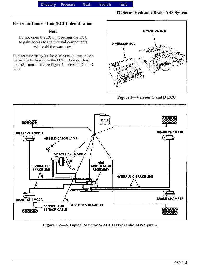
Electronic Control Unit (ECU) Identification
Note
Do not open the ECU. Opening the ECUto gain access to the internal components
will void the warranty.
To determine the hydraulic ABS version installed onthe vehicle by looking at the ECU. D version hasthree (3) connectors, see Figure 1—Version C and DECU.
Figure 1—Version C and D ECU
Figure 1.2—A Typical Meritor WABCO Hydraulic ABS System
TC Series Hydraulic Brake ABS System
030.1-5
System ComponentsThe following components are the Meritor WABCOHydraulic ABS:
• Electronic Control Unit, see Figure 1.3—Electronic Control Unit
1. Processes sensor signals and generates solenoidvalve commands to reduce maintain or reapplybrake pressure.
2. Mounting locations vary, depending on thevehicle specifications for the exact location.
Figure 1.3—Electronic Control Unit
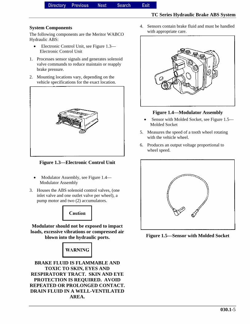
• Modulator Assembly, see Figure 1.4—Modulator Assembly
3. Houses the ABS solenoid control valves, (oneinlet valve and one outlet valve per wheel), apump motor and two (2) accumulators.
Modulator should not be exposed to impactloads, excessive vibrations or compressed air
blown into the hydraulic ports.
BRAKE FLUID IS FLAMMABLE ANDTOXIC TO SKIN, EYES AND
RESPIRATORY TRACT. SKIN AND EYEPROTECTION IS REQUIRED. AVOID
REPEATED OR PROLONGED CONTACT.DRAIN FLUID IN A WELL-VENTILATED
AREA.
4. Sensors contain brake fluid and must be handledwith appropriate care.
Figure 1.4—Modulator Assembly• Sensor with Molded Socket, see Figure 1.5—
Molded Socket
5. Measures the speed of a tooth wheel rotatingwith the vehicle wheel.
6. Produces an output voltage proportional towheel speed.
Figure 1.5—Sensor with Molded Socket
TC Series Hydraulic Brake ABS System
030.1-6
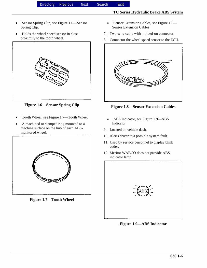
• Sensor Spring Clip, see Figure 1.6—SensorSpring Clip.
• Holds the wheel speed sensor in closeproximity to the tooth wheel.
Figure 1.6—Sensor Spring Clip
• Tooth Wheel, see Figure 1.7—Tooth Wheel
• A machined or stamped ring mounted to amachine surface on the hub of each ABS-monitored wheel.
Figure 1.7—Tooth Wheel
• Sensor Extension Cables, see Figure 1.8—Sensor Extension Cables
7. Two-wire cable with molded-on connector.
8. Connector the wheel speed sensor to the ECU.
Figure 1.8—Sensor Extension Cables
• ABS Indicator, see Figure 1.9—ABSIndicator
9. Located on vehicle dash.
10. Alerts driver to a possible system fault.
11. Used by service personnel to display blinkcodes.
12. Meritor WABCO does not provide ABSindicator lamp.
Figure 1.9—ABS Indicator
TC Series Hydraulic Brake ABS System
030.1-7
Component Removal and Installation
Sensors
• Sensor Lubrication Specification
Meritor WABCO specifications require a sensorlubricant to have the following properties.
1. Lube must be mineral oil-based and containmolydisulfide.
2. Lube should have excellent anti-corrosion andadhesion properties, and be capable ofcontinuous function in a temperature range of
3. –40° to +300° Fahrenheit.
Wheel Speed Sensor Replacement – FrontAxle
Removal
CHOCK THE WHEELS TO PREVENTTHE VEHICLE FROM MOVING.
SUPPORT THE VEHICLE WITH SAFETYSTANDS. DO NOT WORK UNDER A
VEHICLE SUPPORTED ONLY BY JACKS.
TO AVOID DAMAGE TO THEELECTRICAL SYSTEM OR ABS
COMPONENTS, WHEN WELDING ON ANABS-EQUIPPED VEHICLE DISCONNECTTHE POWER CONNECTOR FROM THE
ECU.
1. Apply the parking brakes. Chock the rear tiresto prevent vehicle movement.
2. Disconnect the fasteners that hold the sensorcable to other components.
3. Disconnect the sensor cable from the chassisharness.
4. Remove the sensor from the sensor holder.
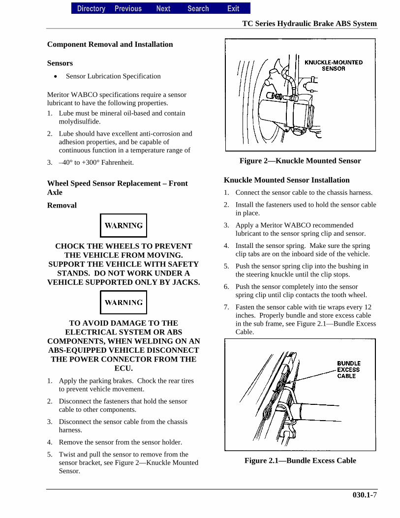
5. Twist and pull the sensor to remove from thesensor bracket, see Figure 2—Knuckle MountedSensor.
Figure 2—Knuckle Mounted Sensor
Knuckle Mounted Sensor Installation
1. Connect the sensor cable to the chassis harness.
2. Install the fasteners used to hold the sensor cablein place.
3. Apply a Meritor WABCO recommendedlubricant to the sensor spring clip and sensor.
4. Install the sensor spring. Make sure the springclip tabs are on the inboard side of the vehicle.
5. Push the sensor spring clip into the bushing inthe steering knuckle until the clip stops.
6. Push the sensor completely into the sensorspring clip until clip contacts the tooth wheel.
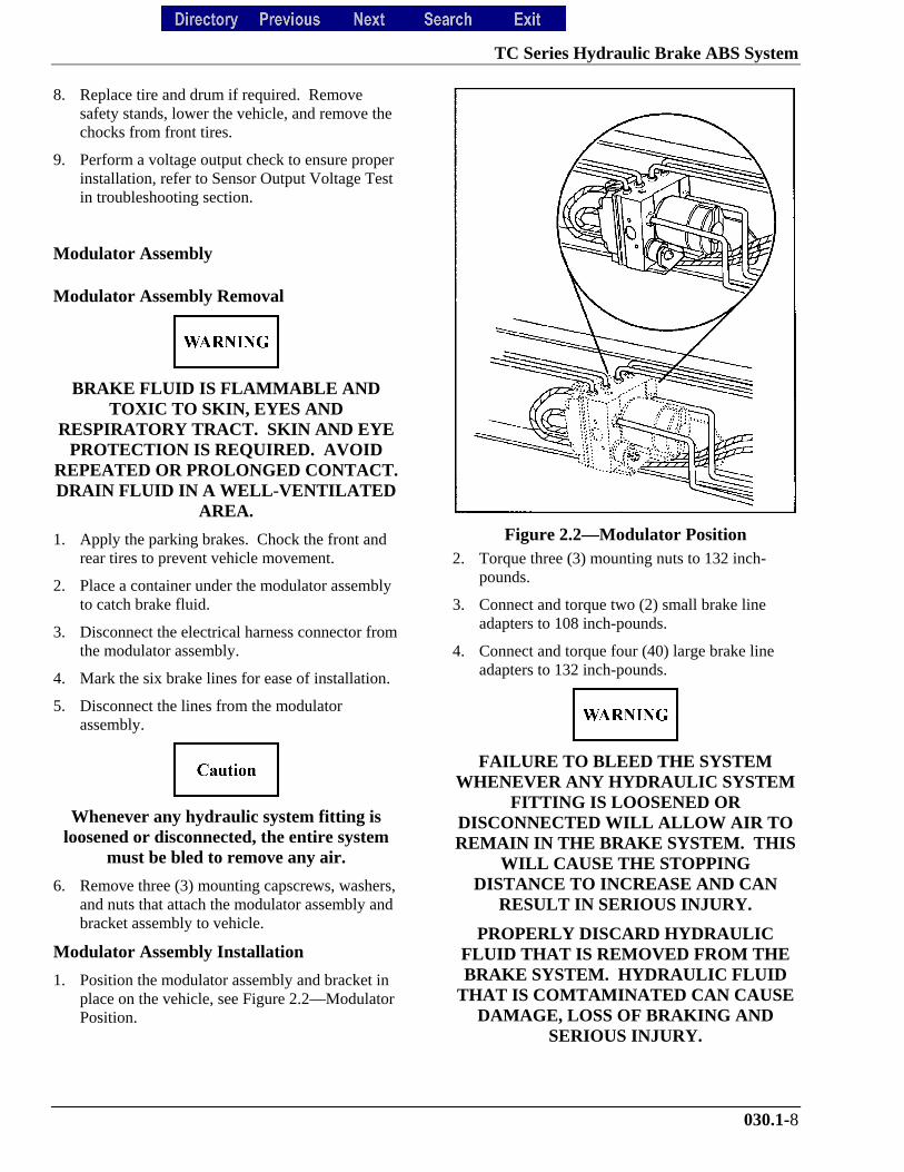
7. Fasten the sensor cable with tie wraps every 12inches. Properly bundle and store excess cablein the sub frame, see Figure 2.1—Bundle ExcessCable.
Figure 2.1—Bundle Excess Cable
TC Series Hydraulic Brake ABS System
030.1-8
8. Replace tire and drum if required. Removesafety stands, lower the vehicle, and remove thechocks from front tires.
9. Perform a voltage output check to ensure properinstallation, refer to Sensor Output Voltage Testin troubleshooting section.
Modulator Assembly
Modulator Assembly Removal
BRAKE FLUID IS FLAMMABLE ANDTOXIC TO SKIN, EYES AND
RESPIRATORY TRACT. SKIN AND EYEPROTECTION IS REQUIRED. AVOID
REPEATED OR PROLONGED CONTACT.DRAIN FLUID IN A WELL-VENTILATED
AREA.
1. Apply the parking brakes. Chock the front andrear tires to prevent vehicle movement.
2. Place a container under the modulator assemblyto catch brake fluid.
3. Disconnect the electrical harness connector fromthe modulator assembly.
4. Mark the six brake lines for ease of installation.
5. Disconnect the lines from the modulatorassembly.
Whenever any hydraulic system fitting isloosened or disconnected, the entire system
must be bled to remove any air.
6. Remove three (3) mounting capscrews, washers,and nuts that attach the modulator assembly andbracket assembly to vehicle.
Modulator Assembly Installation
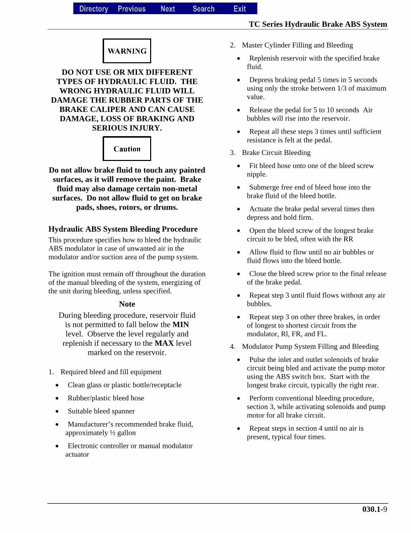
1. Position the modulator assembly and bracket inplace on the vehicle, see Figure 2.2—ModulatorPosition.
Figure 2.2—Modulator Position2. Torque three (3) mounting nuts to 132 inch-
pounds.
3. Connect and torque two (2) small brake lineadapters to 108 inch-pounds.
4. Connect and torque four (40) large brake lineadapters to 132 inch-pounds.
FAILURE TO BLEED THE SYSTEMWHENEVER ANY HYDRAULIC SYSTEM
FITTING IS LOOSENED ORDISCONNECTED WILL ALLOW AIR TOREMAIN IN THE BRAKE SYSTEM. THIS
WILL CAUSE THE STOPPINGDISTANCE TO INCREASE AND CAN
RESULT IN SERIOUS INJURY.
PROPERLY DISCARD HYDRAULICFLUID THAT IS REMOVED FROM THEBRAKE SYSTEM. HYDRAULIC FLUID
THAT IS COMTAMINATED CAN CAUSEDAMAGE, LOSS OF BRAKING AND
SERIOUS INJURY.
TC Series Hydraulic Brake ABS System
030.1-9
DO NOT USE OR MIX DIFFERENTTYPES OF HYDRAULIC FLUID. THEWRONG HYDRAULIC FLUID WILL
DAMAGE THE RUBBER PARTS OF THEBRAKE CALIPER AND CAN CAUSEDAMAGE, LOSS OF BRAKING AND
SERIOUS INJURY.
Do not allow brake fluid to touch any paintedsurfaces, as it will remove the paint. Brakefluid may also damage certain non-metal
surfaces. Do not allow fluid to get on brakepads, shoes, rotors, or drums.
Hydraulic ABS System Bleeding ProcedureThis procedure specifies how to bleed the hydraulicABS modulator in case of unwanted air in themodulator and/or suction area of the pump system.
The ignition must remain off throughout the durationof the manual bleeding of the system, energizing ofthe unit during bleeding, unless specified.
Note
During bleeding procedure, reservoir fluidis not permitted to fall below the MINlevel. Observe the level regularly and
replenish if necessary to the MAX levelmarked on the reservoir.
1. Required bleed and fill equipment
• Clean glass or plastic bottle/receptacle
• Rubber/plastic bleed hose
• Suitable bleed spanner
• Manufacturer’s recommended brake fluid,approximately ½ gallon
• Electronic controller or manual modulatoractuator
2. Master Cylinder Filling and Bleeding
• Replenish reservoir with the specified brakefluid.
• Depress braking pedal 5 times in 5 secondsusing only the stroke between 1/3 of maximumvalue.
• Release the pedal for 5 to 10 seconds Airbubbles will rise into the reservoir.
• Repeat all these steps 3 times until sufficientresistance is felt at the pedal.
3. Brake Circuit Bleeding
• Fit bleed hose onto one of the bleed screwnipple.
• Submerge free end of bleed hose into thebrake fluid of the bleed bottle.
• Actuate the brake pedal several times thendepress and hold firm.
• Open the bleed screw of the longest brakecircuit to be bled, often with the RR
• Allow fluid to flow until no air bubbles orfluid flows into the bleed bottle.
• Close the bleed screw prior to the final releaseof the brake pedal.
• Repeat step 3 until fluid flows without any airbubbles.
• Repeat step 3 on other three brakes, in orderof longest to shortest circuit from themodulator, Rl, FR, and FL.
4. Modulator Pump System Filling and Bleeding
• Pulse the inlet and outlet solenoids of brakecircuit being bled and activate the pump motorusing the ABS switch box. Start with thelongest brake circuit, typically the right rear.
• Perform conventional bleeding procedure,section 3, while activating solenoids and pumpmotor for all brake circuit.
• Repeat steps in section 4 until no air ispresent, typical four times.
TC Series Hydraulic Brake ABS System
030.1-10
Manual Bleeding
BRAKE FLUID IS FLAMMABLE ANDTOXIC TO SKIN, EYES AND
RESPIRATORY TRACT. SKIN AND EYEPROTECTION IS REQUIRED. AVOID
REPEATED OR PROLONGED CONTACT.DRAIN FLUID IN A WELL-VENTILATED
AREA.
Do not let the brake master cylinder fluidlevel get too low during the bleeding
operation.
1. Apply the parking brake and chock the wheels.
2. Bleed the master cylinder, see Figure 2.3—RearBleeding Location.
Figure 2.3—Rear Bleeding Location3. Loosen the fitting at the rear outlet port on the
master cylinder until the fluid begins to flow.
4. Push the brake pedal down slowly until thepedal reaches the floor. Brake fluid and any airin the master cylinder will discharge through thefitting.
Do not release the brake pedal until thefitting has been tightened. Failure to do so
will allow air bake into the system.
5. Press the brake pedal down, hand tighten therear hydraulic line fitting.
6. Release the brake pedal.
7. Loosen fitting again and repeat steps 1 through6.
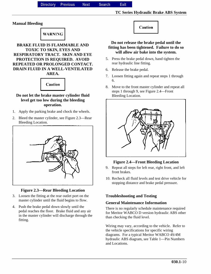
8. Move to the front master cylinder and repeat allsteps 1 through 9, see Figure 2.4—FrontBleeding Location.
Figure 2.4—Front Bleeding Location9. Repeat all steps for left rear, right front, and left
front brakes.
10. Recheck all fluid levels and test drive vehicle forstopping distance and brake pedal pressure.
Troubleshooting and Testing
General Maintenance Information There is no regularly schedule maintenance requiredfor Meritor WABCO D version hydraulic ABS otherthan checking the fluid level.
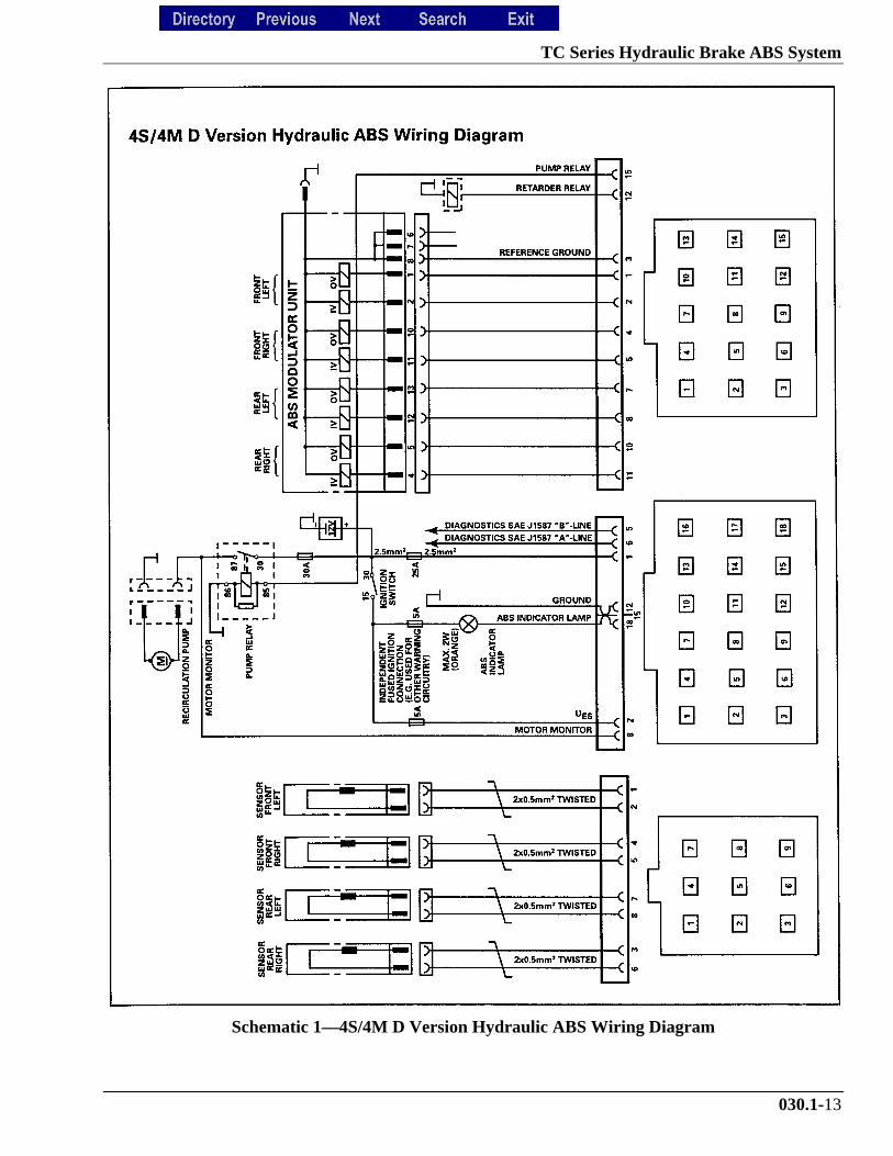
Wiring may vary, according to the vehicle. Refer tothe vehicle specifications for specific wiringdiagrams. For a typical Meritor WABCO 4S/4Mhydraulic ABS diagram, see Table 1—Pin Numbersand Locations.
TC Series Hydraulic Brake ABS System
030.1-11
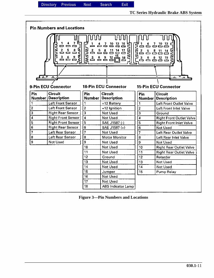
Figure 3—Pin Numbers and Locations
TC Series Hydraulic Brake ABS System
030.1-12
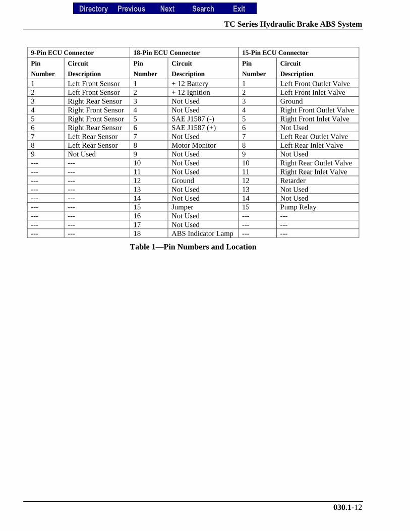
9-Pin ECU Connector 18-Pin ECU Connector 15-Pin ECU Connector
Pin
Number
Circuit
Description
Pin
Number
Circuit
Description
Pin
Number
Circuit
Description
1 Left Front Sensor 1 + 12 Battery 1 Left Front Outlet Valve2 Left Front Sensor 2 + 12 Ignition 2 Left Front Inlet Valve3 Right Rear Sensor 3 Not Used 3 Ground4 Right Front Sensor 4 Not Used 4 Right Front Outlet Valve5 Right Front Sensor 5 SAE J1587 (-) 5 Right Front Inlet Valve6 Right Rear Sensor 6 SAE J1587 (+) 6 Not Used7 Left Rear Sensor 7 Not Used 7 Left Rear Outlet Valve8 Left Rear Sensor 8 Motor Monitor 8 Left Rear Inlet Valve9 Not Used 9 Not Used 9 Not Used--- --- 10 Not Used 10 Right Rear Outlet Valve--- --- 11 Not Used 11 Right Rear Inlet Valve--- --- 12 Ground 12 Retarder--- --- 13 Not Used 13 Not Used--- --- 14 Not Used 14 Not Used--- --- 15 Jumper 15 Pump Relay--- --- 16 Not Used --- ------ --- 17 Not Used --- ------ --- 18 ABS Indicator Lamp --- ---
Table 1—Pin Numbers and Location
TC Series Hydraulic Brake ABS System
030.1-13
Schematic 1—4S/4M D Version Hydraulic ABS Wiring Diagram
TC Series Hydraulic Brake ABS System
030.1-14
Blink Code Diagnostics
• ABS Indicator Lamp
This lamp, located on the vehicle dash, serves twopurposes:
1. Alerts drivers or service personnel to a possiblefault in the hydraulic ABS, as follows:
• If the ABS indicator lamp comes on brieflythen goes to off when the ignition is turned on,there are no active or stored faults in thehydraulic ABS.
• If the ABS indicator lamp comes on and stayson after the ignition is turned on and thevehicle is driven in excess of 4 mph, there maybe an active fault in the hydraulic ABS.
• If ABS indicator lamp comes on and stays onand Goes off after the vehicle is driven morethan 4 mph there may be a stored fault in thehydraulic ABS.
• Displays diagnostic blink codes for servicing.
Definitions
• Blink Code:
A series of blinks or flashes that describe aparticular ABS system condition.
• Blink Code Diagnostics:
The ability of the Meritor WABCO ECU tosense faults in the ABS system and to definethese faults using blink codes.
• Blink Code Switch:
A momentary switch that activates blink codediagnostic capabilities. Usually, it is mountedunder the dash or on the steering column.
• Clearing Fault Codes:
The process of erasing faults from the ECUmemory bank.
• Fault Code:
An ABS condition (fault) detected and stored inmemory by the Meritor WABCO ECU anddisplayed by blink code. System faults may beActive or Stored.
• Active Fault:
A condition that currently exists in the ABSsystem; for example, a sensor circuitmalfunction on the left front steering axle. Anactive fault must be repaired before additionalfaults can be displayed. When an active faulthas been repaired, it becomes a stored fault.
• Stored Fault:
A condition that caused the system to register afault but is not currently active. For example, aloose wire that corrected itself. A stored fault canalso be an active fault that has been corrected.
• Table 2 describes the method ofdistinguishing between active and stored faultsand explains how to clear them.
Using Blink Code Diagnostics
• Observe the steps in Table 2—Identifying DVersion Hydraulic ABS Blink Codes.
TC Series Hydraulic Brake ABS System
030.1-15
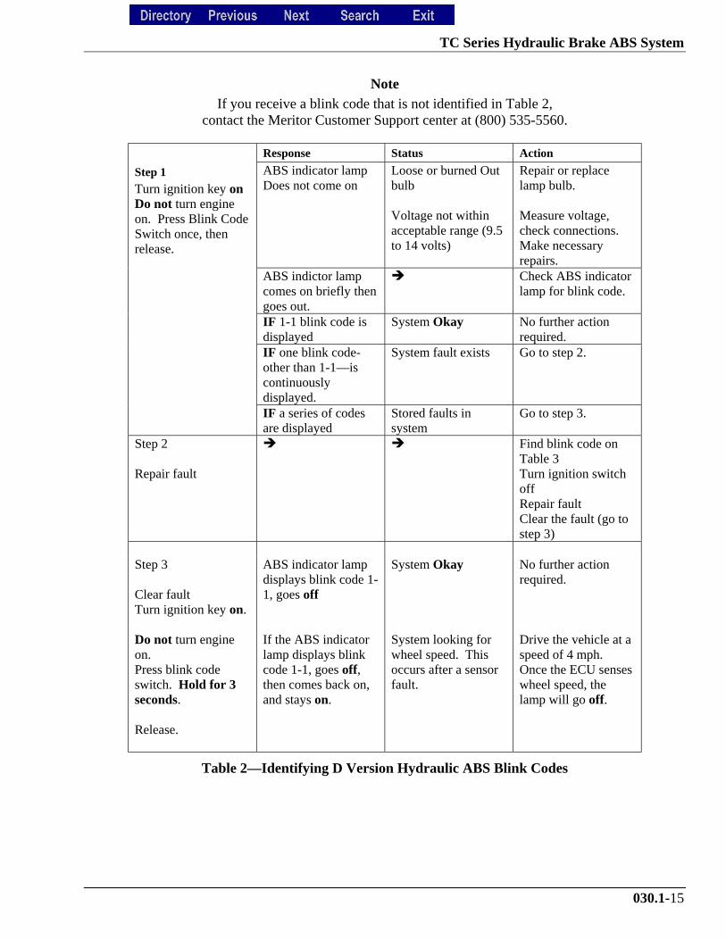
Note
If you receive a blink code that is not identified in Table 2,contact the Meritor Customer Support center at (800) 535-5560.
Response Status Action
Step 1
Turn ignition key onDo not turn engineon. Press Blink CodeSwitch once, thenrelease.
ABS indicator lampDoes not come on
Loose or burned Outbulb
Voltage not withinacceptable range (9.5to 14 volts)
Repair or replacelamp bulb.
Measure voltage,check connections.Make necessaryrepairs.
ABS indictor lampcomes on briefly thengoes out.
! Check ABS indicatorlamp for blink code.
IF 1-1 blink code isdisplayed
System Okay No further actionrequired.
IF one blink code-other than 1-1—iscontinuouslydisplayed.
System fault exists Go to step 2.
IF a series of codesare displayed
Stored faults insystem
Go to step 3.
Step 2
Repair fault
! ! Find blink code onTable 3Turn ignition switchoffRepair faultClear the fault (go tostep 3)
Step 3
Clear faultTurn ignition key on.
Do not turn engineon.Press blink codeswitch. Hold for 3seconds.
Release.
ABS indicator lampdisplays blink code 1-1, goes off
If the ABS indicatorlamp displays blinkcode 1-1, goes off,then comes back on,and stays on.
System Okay
System looking forwheel speed. Thisoccurs after a sensorfault.
No further actionrequired.
Drive the vehicle at aspeed of 4 mph.Once the ECU senseswheel speed, thelamp will go off.
Table 2—Identifying D Version Hydraulic ABS Blink Codes
TC Series Hydraulic Brake ABS System
030.1-16
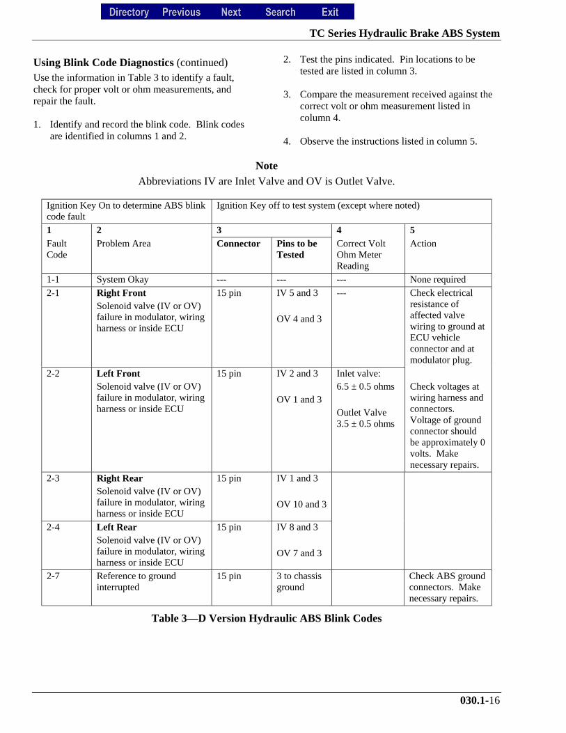
Using Blink Code Diagnostics (continued)Use the information in Table 3 to identify a fault,check for proper volt or ohm measurements, andrepair the fault.
1. Identify and record the blink code. Blink codesare identified in columns 1 and 2.
2. Test the pins indicated. Pin locations to betested are listed in column 3.
3. Compare the measurement received against thecorrect volt or ohm measurement listed incolumn 4.
4. Observe the instructions listed in column 5.
Note
Abbreviations IV are Inlet Valve and OV is Outlet Valve.
Ignition Key On to determine ABS blinkcode fault
Ignition Key off to test system (except where noted)
1 2 3 4 5FaultCode
Problem Area Connector Pins to beTested
Correct VoltOhm MeterReading
Action
1-1 System Okay --- --- --- None required
2-1 Right FrontSolenoid valve (IV or OV)failure in modulator, wiringharness or inside ECU
15 pin IV 5 and 3
OV 4 and 3
--- Check electricalresistance ofaffected valvewiring to ground atECU vehicleconnector and atmodulator plug.
2-2 Left FrontSolenoid valve (IV or OV)failure in modulator, wiringharness or inside ECU
15 pin IV 2 and 3
OV 1 and 3
Inlet valve:6.5 ± 0.5 ohms
Outlet Valve3.5 ± 0.5 ohms
Check voltages atwiring harness andconnectors.Voltage of groundconnector shouldbe approximately 0volts. Makenecessary repairs.
2-3 Right RearSolenoid valve (IV or OV)failure in modulator, wiringharness or inside ECU
15 pin IV 1 and 3
OV 10 and 3
2-4 Left RearSolenoid valve (IV or OV)failure in modulator, wiringharness or inside ECU
15 pin IV 8 and 3
OV 7 and 3
2-7 Reference to groundinterrupted
15 pin 3 to chassisground
Check ABS groundconnectors. Makenecessary repairs.
Table 3—D Version Hydraulic ABS Blink Codes
TC Series Hydraulic Brake ABS System
030.1-17
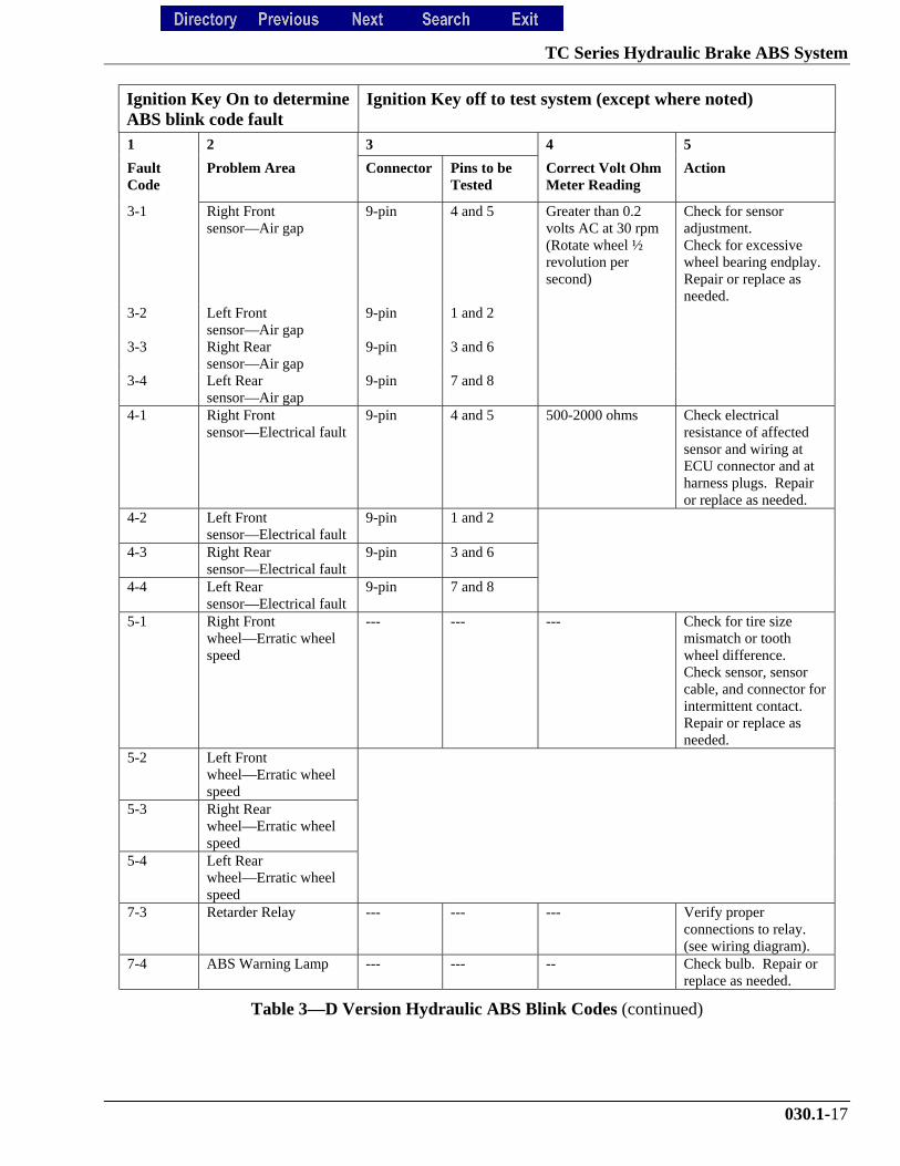
Ignition Key On to determineABS blink code fault
Ignition Key off to test system (except where noted)
1 2 3 4 5
FaultCode
Problem Area Connector Pins to beTested
Correct Volt OhmMeter Reading
Action
3-1 Right Frontsensor—Air gap
9-pin 4 and 5 Greater than 0.2volts AC at 30 rpm(Rotate wheel ½revolution persecond)
Check for sensoradjustment.Check for excessivewheel bearing endplay.Repair or replace asneeded.
3-2 Left Frontsensor—Air gap
9-pin 1 and 2
3-3 Right Rearsensor—Air gap
9-pin 3 and 6
3-4 Left Rearsensor—Air gap
9-pin 7 and 8
4-1 Right Frontsensor—Electrical fault
9-pin 4 and 5 500-2000 ohms Check electricalresistance of affectedsensor and wiring atECU connector and atharness plugs. Repairor replace as needed.
4-2 Left Frontsensor—Electrical fault
9-pin 1 and 2
4-3 Right Rearsensor—Electrical fault
9-pin 3 and 6
4-4 Left Rearsensor—Electrical fault
9-pin 7 and 8
5-1 Right Frontwheel—Erratic wheelspeed
--- --- --- Check for tire sizemismatch or toothwheel difference.Check sensor, sensorcable, and connector forintermittent contact.Repair or replace asneeded.
5-2 Left Frontwheel—Erratic wheelspeed
5-3 Right Rearwheel—Erratic wheelspeed
5-4 Left Rearwheel—Erratic wheelspeed
7-3 Retarder Relay --- --- --- Verify properconnections to relay.(see wiring diagram).
7-4 ABS Warning Lamp --- --- -- Check bulb. Repair orreplace as needed.
Table 3—D Version Hydraulic ABS Blink Codes (continued)
TC Series Hydraulic Brake ABS System
030.1-18
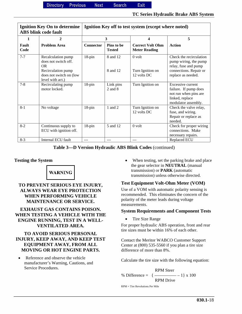
Ignition Key On to determineABS blink code fault
Ignition Key off to test system (except where noted)
1 2 3 4 5
FaultCode
Problem Area Connector Pins to beTested
Correct Volt OhmMeter Reading
Action
7-7 Recalculation pumpdoes not switch off.ORRecirculation pumpdoes not switch on (lowlevel with act.)
18-pin 8 and 12
8 and 12
0 volt
Turn Ignition on12 volts DC
Check the recirculationpump wiring, the pumprelay, fuse and pumpconnections. Repair orreplace as needed.
7-8 Recirculating pumpmotor locked.
18-pin Link pins2 and 8
Turn Ignition on Excessive currentfailure. If pump doesnot run when pins arelinked, replacemodulator assembly.
8-1 No voltage 18-pin 1 and 2 Turn Ignition on12 volts DC
Check the valve relay,fuse, and wiring.Repair or replace asneeded.
8-2 Continuous supply toECU with ignition off.
18-pin 5 and 12 0 volt Check for proper wiringconnections. Makenecessary repairs.
8-3 Internal ECU fault --- --- --- Replaced ECU
Table 3—D Version Hydraulic ABS Blink Codes (continued)
Testing the System
TO PREVENT SERIOUS EYE INJURY,ALWAYS WEAR EYE PROTECTION
WHEN PERFORMING VEHICLEMAINTENANCE OR SERVICE.
EXHAUST GAS CONTAINS POISON.WHEN TESTING A VEHICLE WITH THE
ENGINE RUNNING, TEST IN A WELL-VENTILATED AREA.
TO AVOID SERIOUS PERSONALINJURY, KEEP AWAY, AND KEEP TEST
EQUIPMENT AWAY, FROM ALLMOVING OR HOT ENGINE PARTS.
• Reference and observe the vehiclemanufacturer’s Warning, Cautions, andService Procedures.
• When testing, set the parking brake and placethe gear selector in NEUTRAL (manualtransmission) or PARK (automatictransmission) unless otherwise directed.
Test Equipment Volt-Ohm Meter (VOM)Use of a VOM with automatic polarity sensing isrecommended. This eliminates the concern of thepolarity of the meter leads during voltagemeasurements.
System Requirements and Component Tests
• Tire Size Range
For proper hydraulic ABS operation, front and reartire sizes must be within 16% of each other.
Contact the Meritor WABCO Customer SupportCenter at (800) 535-5560 if you plan a tire sizedifference of more than 8%.
Calculate the tire size with the following equation:
RPM Steer % Difference = { ————— – 1} x 100 RPM DriveRPM = Tire Revolutions Per Mile
TC Series Hydraulic Brake ABS System
030.1-19
When troubleshooting or testing the ABSsystem, do not damage the connector
terminals.
Voltage CheckVoltage must be between 9.5 and 14 volts for the 12volt hydraulic ABS to function properly.
• To check voltage
1. Turn ignition on.
2. Check for proper voltage between pins (12 and1) and (12 and 2) on the 18 pin connector.
3. If voltage is not between 9.5 and 14 volts, verifyproper wiring connections. Make corrections asrequired.
ABS IndicatorIf the ABS indicator lamp does not come on after theignition is turned on, or it comes on but does not goout after 3 seconds, check all ABS fuses or circuitbreakers and replace.
Check the wiring to the ABS diagnostic switch andthe indicator lamp. Repair, or replace the wiring asrequired.
• When checking the indicator lamp
1. Check voltage potential at the lamp socket.
2. Check continuity of the wires to the socket.
3. Replace bulb.
ABS Diagnostic Switch
• When testing the ABS diagnostic switch
1. Check the resistance between the terminalswhile cycling the switch.
2. Check the continuity of the wires to the switch(pins 5 and 12) and (6 and 12) on the 18 pinconnector.
Sensor Adjustment
Do not pry or push sensors with sharpobjects.
Note
Sensor will self-adjust during wheelrotation.
No gap is allowed at installation. Duringnormal operation, a gap not exceeding
0.04 inch is allowable.
To adjust the sensor, push the sensor in until itcontacts the tooth wheel.
Sensor Output Voltage Test
• Sensor output voltage must be at least 0.2volts AC at 30 rpm. Test the sensor outputvoltage.
1. Turn ignition off.
2. Disconnect the ECU. Measure voltage at thepins on the ECU connector, disconnect thesensor from the sensor extension cable.
3. Put blocks under the front and rear tires to keepthe vehicle from moving.
CHOCK THE WHEELS TO PREVENTTHE VEHICLE FROM MOVING.
SUPPORT THE VEHICLE WITH SAFETYSTANDS. DO NOT WORK UNDER A
VEHICLE SUPPORTED ONLY BY JACKS.
4. Raise the vehicle off the ground. Put safetystands under the axle.
5. Rotate wheel by hand at 30 rpm (1/2 revolutionper second).
6. Measure the voltage at the pins, see Table 4—Sensor Check Pins.
TC Series Hydraulic Brake ABS System
030.1-20
Sensor Resistance
• The sensor circuit resistance must be between500 and 2000 ohms. Measure resistance at thesensor connector, or at the pins on the ECUconnector.
7. Turn ignition off.
• To measure resistance at the pins on ECUconnector, disconnect the ECU from the sensorextension cable.
• To measure resistance at the sensor connector,disconnect the sensor from the sensorextension cable.
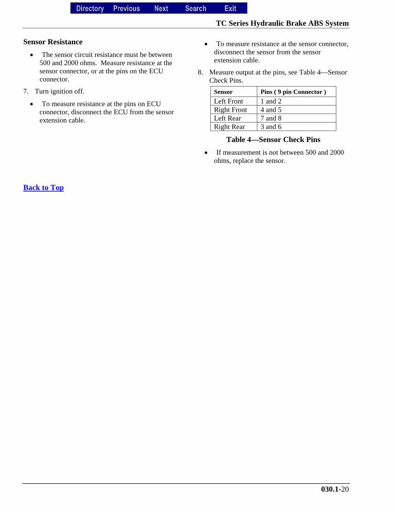
8. Measure output at the pins, see Table 4—SensorCheck Pins.
Sensor Pins ( 9 pin Connector )
Left Front 1 and 2Right Front 4 and 5Left Rear 7 and 8Right Rear 3 and 6
Table 4—Sensor Check Pins
• If measurement is not between 500 and 2000ohms, replace the sensor.
Back to Top