Embed Size (px)
Citation preview
I. OBJECTIVE OF THE EXPERIMENT
We would like to study different physical systems capable of measuring temperature in a large range: platinum probe, thermocouple, gas thermometer and pyrometer
We will learn how to connect a Pt100 probe electrically and calibrate it, how to calibrate a thermocouple, how to operate a gas thermometer, and calibrate a pyrometer using a thermocouple.
II. TEMPERATURE MEASUREMENT
Temperature is a sensorial notion, that has to do with a hot or cold feeling after a thermal contact. The
idea of a thermal contact strikes us as important. By thermal contact is implied any process allowing
heat to be exchanged between two systems (conduction, convection, radiation). If there is a thermal
contact between two bodies, both of the temperature vary until they reach an equilibrium (supposing
both systems are well isolated from external fluctuations). A thermal equilibrium, we can generalize by
expressing a principle:
Two bodies in thermal contact have the same temperature.
and
If two systems A and B are in thermal equilibrium with a system C, then they are in thermal
equilibrium with one another
This is the zeroth principle of thermodynamics
The use of thermometers is entirely based on this principle, since a thermometer can only ever
indicate its own temperature.
Therefore, in order to measure a temperature, on must:
a) Choose a system (thermometer) that has a value that evolves with temperature. This is called the
thermometric value
Examples: the volume of a liquid (alcohol thermometer), the resistance of a wire (resistance
thermometer), the pressure of a gas at constant volume (gas thermometer).
b) Choose fixed arbitrary points (triple point of water, boiling temperature of water at atmospheric
pressure, etc...) and give those points an arbitrary value (Triple point of water: 273.16 K).
c) In order to describe the temperature in between, choose an arbitrary conversion law linking the
thermometric value to the temperature.
EPFL-TRAVAUX PRATIQUES DE PHYSIQUE C7-2
Fixed point allowing the calibration of thermometers
Substance T [ ]C
_________________________________________________
* Boiling Nitrogen -195,8
* Acetone + solid CO2 - 86
* Melting Ice - 0,01
* Boiling water at 720 torr 98,5
* Melting point of tin 213,9
* Melting point of lead 327,5
* Melting point of zinc 419,6
* Melting point of sulfur 444,7
* Melting point of aluminum 660,4
* Melting point of silver 961,9
* Melting point of gold 1064,4
* Melting point of copper 1084,5
* Melting point of platinum 1772
III. EXEMPLES DE THERMOMETRES:
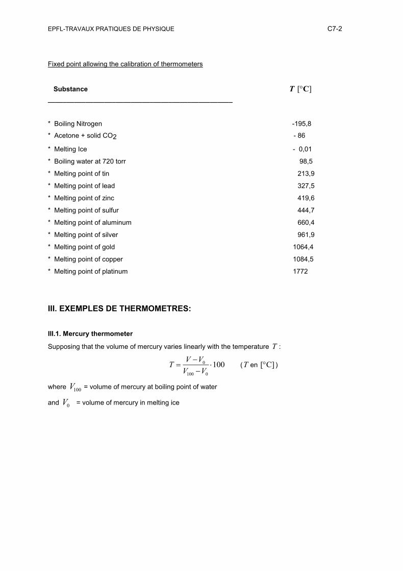
III.1. Mercury thermometer
Supposing that the volume of mercury varies linearly with the temperature T :
0
100 0
100
V VT
V V (T en [ C] )
where V100 = volume of mercury at boiling point of water
and V0 = volume of mercury in melting ice
EPFL-TRAVAUX PRATIQUES DE PHYSIQUE C7-3
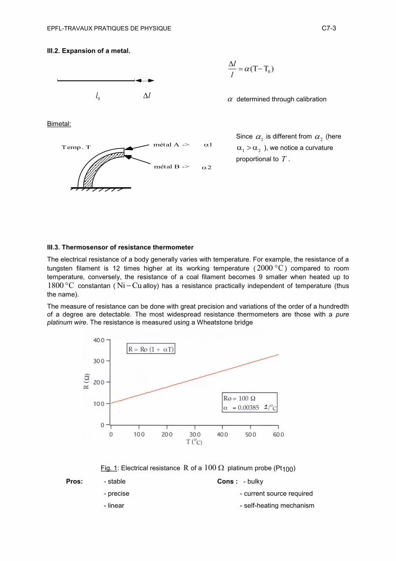
III.2. Expansion of a metal.
0l l
0(T T )
l
l
determined through calibration
Bimetal:
Since a1 is different from a2 (here
1 2 ), we notice a curvature
proportional to T .
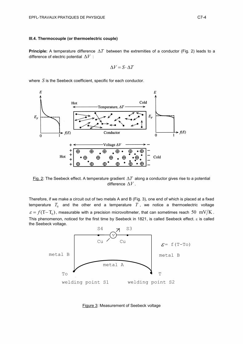
III.3. Thermosensor of resistance thermometer
The electrical resistance of a body generally varies with temperature. For example, the resistance of a
tungsten filament is 12 times higher at its working temperature ( 2000 C ) compared to room
temperature, conversely, the resistance of a coal filament becomes 9 smaller when heated up to
1800 C constantan ( Ni Cu alloy) has a resistance practically independent of temperature (thus
the name).
The measure of resistance can be done with great precision and variations of the order of a hundredth
of a degree are detectable. The most widespread resistance thermometers are those with a pure
platinum wire. The resistance is measured using a Wheatstone bridge
Fig. 1: Electrical resistance R of a 100 platinum probe (Pt100)
Pros: - stable
- precise
- linear
Cons : - bulky
- current source required
- self-heating mechanism
Temp. Tmétal A ->
métal B ->
EPFL-TRAVAUX PRATIQUES DE PHYSIQUE C7-4
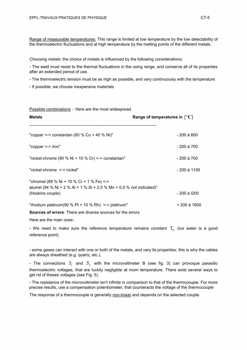
III.4. Thermocouple (or thermoelectric couple)
Principle: A temperature difference T between the extremities of a conductor (Fig. 2) leads to a
difference of electric potential V :
V S T
where S is the Seebeck coefficient, specific for each conductor.
Fig. 2: The Seebeck effect. A temperature gradient T along a conductor gives rise to a potential
difference V .
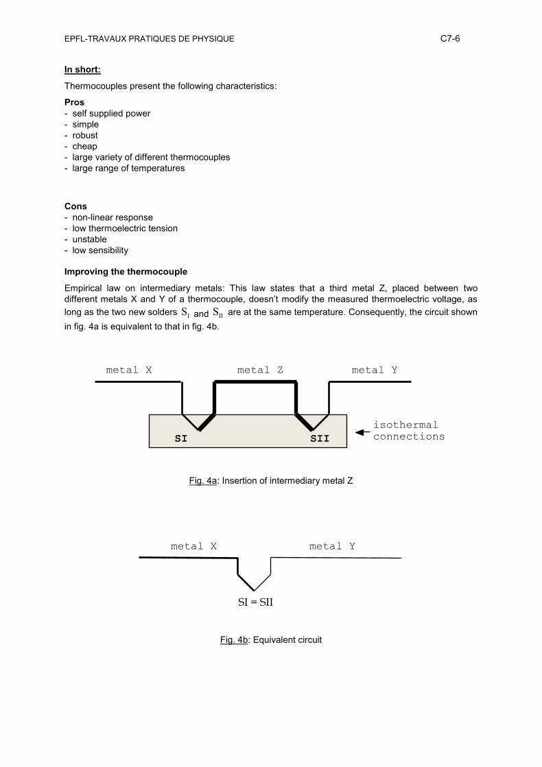
Therefore, if we make a circuit out of two metals A and B (Fig. 3), one end of which is placed at a fixed
temperature 0T and the other end a temperature T , we notice a thermoelectric voltage
0(T T ) f , measurable with a precision microvoltmeter, that can sometimes reach 50 mV K .
This phenomenon, noticed for the first time by Seebeck in 1821, is called Seebeck effect. is called
the Seebeck voltage.
Figure 3: Measurement of Seebeck voltage
welding point S2 welding point S1
metal B
Cu Cu
= f(T-To)
metal B
metal A
T To
S3
S4
v
EPFL-TRAVAUX PRATIQUES DE PHYSIQUE C7-5
Range of measurable temperatures: This range is limited at low temperature by the low delectability of
the thermoelectric fluctuations and at high temperature by the melting points of the different metals.
Choosing metals: the choice of metals is influenced by the following considerations:
- The weld must resist to the thermal fluctuations in the using range, and conserve all of its properties
after an extended period of use.
- The thermoelectric tension must be as high as possible, and vary continuously with the temperature
- If possible, we choose inexpensive materials
Possible combinations : Here are the most widespread
Metals Range of temperatures in [ ]C
_______________________________________________________
"copper <-> constantan (60 % Cu + 40 % Ni)" - 200 à 600
"copper <-> iron" - 200 à 700
"nickel-chrome (90 % Ni + 10 % Cr) <-> constantan" - 200 à 700
"nickel-chrome <-> nickel" - 200 à 1100
"chromel (89 % Ni + 10 % Cr + 1 % Fe) <->
alumel (94 % Ni + 2 % Al + 1 % Si + 2,5 % Mn + 0,5 % not indicated)"
(Hoskins couple) - 200 à l200
"rhodium platinum(90 % Pt + 10 % Rh) <-> platinum" + 200 à 1600
Sources of errors: There are diverse sources for the errors
Here are the main ones:
- We need to make sure the reference temperature remains constant 0T (ice water is a good
reference point).
- some gases can interact with one or both of the metals, and vary its properties; this is why the cables
are always sheathed (e.g. quartz, etc.).
- The connections 1S and 2S with the microvoltmeter B (see fig. 3) can provoque parasitic
thermoelectric voltages, that are luckily negligible at room temperature. There exist several ways to
get rid of theses voltages (see Fig. 5).
- The resistance of the microvoltmeter isn’t infinite in comparison to that of the thermocouple. For more
precise results, use a compensation potentiometer, that counteracts the voltage of the thermocouple
The response of a thermocouple is generally non-linear and depends on the selected couple.
EPFL-TRAVAUX PRATIQUES DE PHYSIQUE C7-6
In short:
Thermocouples present the following characteristics:
Pros
- self supplied power
- simple
- robust
- cheap
- large variety of different thermocouples
- large range of temperatures
Cons
- non-linear response
- low thermoelectric tension
- unstable
- low sensibility
Improving the thermocouple
Empirical law on intermediary metals: This law states that a third metal Z, placed between two
different metals X and Y of a thermocouple, doesn’t modify the measured thermoelectric voltage, as
long as the two new solders IS and IIS are at the same temperature. Consequently, the circuit shown
in fig. 4a is equivalent to that in fig. 4b.
Fig. 4a: Insertion of intermediary metal Z
Fig. 4b: Equivalent circuit
metal Y metal X metal Z
isothermal
connections SII SI
metal X metal Y
SI = SII
EPFL-TRAVAUX PRATIQUES DE PHYSIQUE C7-7
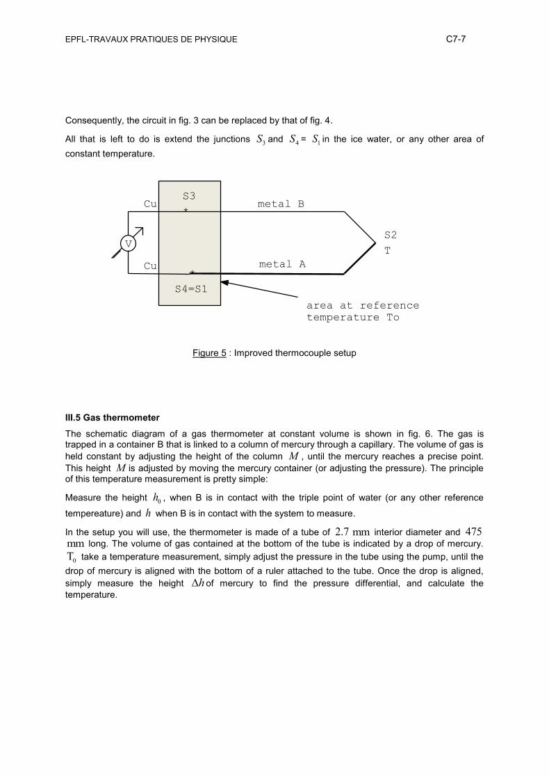
Consequently, the circuit in fig. 3 can be replaced by that of fig. 4.
All that is left to do is extend the junctions 3S and 4S = 1S in the ice water, or any other area of
constant temperature.
Figure 5 : Improved thermocouple setup
III.5 Gas thermometer
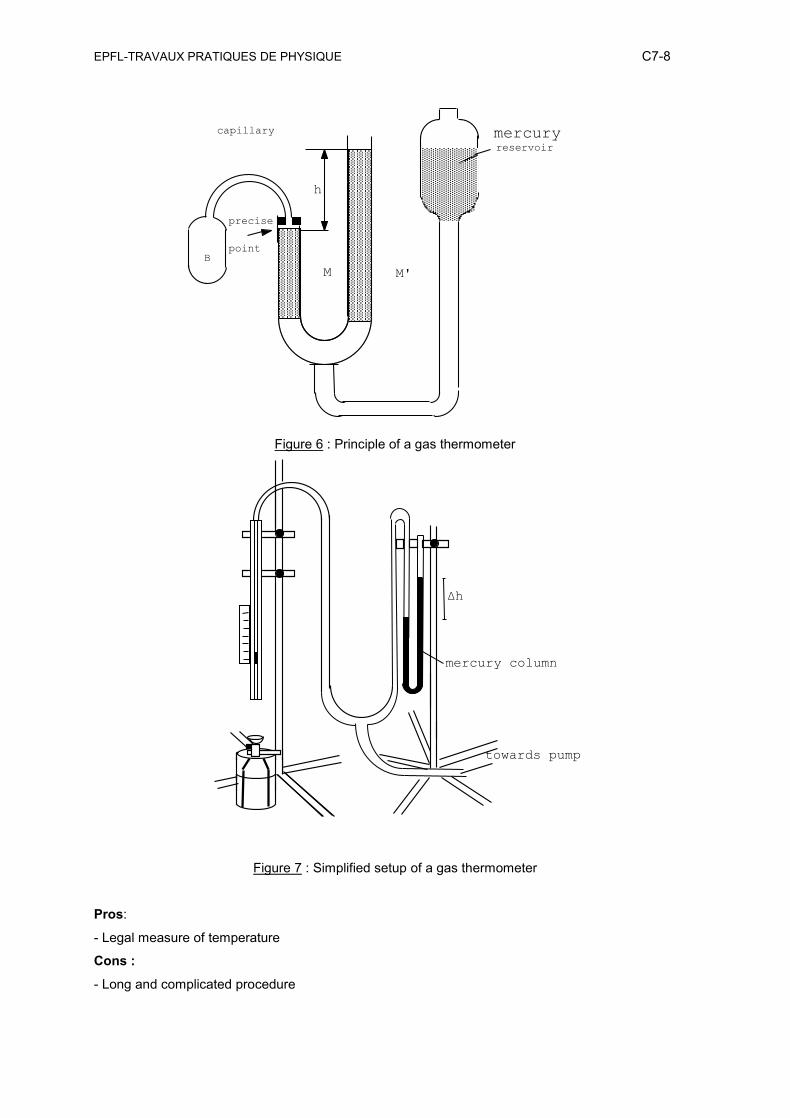
The schematic diagram of a gas thermometer at constant volume is shown in fig. 6. The gas is trapped in a container B that is linked to a column of mercury through a capillary. The volume of gas is
held constant by adjusting the height of the column M , until the mercury reaches a precise point.
This height M is adjusted by moving the mercury container (or adjusting the pressure). The principle of this temperature measurement is pretty simple:
Measure the height 0h , when B is in contact with the triple point of water (or any other reference
tempereature) and h when B is in contact with the system to measure.
In the setup you will use, the thermometer is made of a tube of 2.7 mm interior diameter and 475mm long. The volume of gas contained at the bottom of the tube is indicated by a drop of mercury.
0T take a temperature measurement, simply adjust the pressure in the tube using the pump, until the
drop of mercury is aligned with the bottom of a ruler attached to the tube. Once the drop is aligned,
simply measure the height h of mercury to find the pressure differential, and calculate the
temperature.
V
*
*
S3
S4=S1
Cu
Cu
metal B
metal A
T
S2
area at reference
temperature To
EPFL-TRAVAUX PRATIQUES DE PHYSIQUE C7-8
Figure 6 : Principle of a gas thermometer
Figure 7 : Simplified setup of a gas thermometer
Pros:
- Legal measure of temperature
Cons :
- Long and complicated procedure
mercury reservoir
capillary
point
h
M M'
B
precise
Δh
towards pump
mercury column
EPFL-TRAVAUX PRATIQUES DE PHYSIQUE C7-9
III.6 Optical Pyrometer
We know that when heating a body sufficiently, it turns dark red: this color starts to appear around
500 C . It turns red around 700 C , orange around 1100 C , and gets closer to white around
1300 C . This effect can be used to mesure the temperature.
Disappearing filament pyrometers are made of and objective, pointed towards the object to measure, to get an image on which it superimposes a hating filament. The filament is heated until it is the same color as the background (thus disappearing), at which point it will have reached the same temperature as the object.
This process can be made easier when watching the whole scene through a red filter, that only lets a selected spectral band go through.
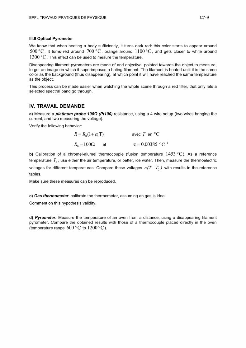
IV. TRAVAIL DEMANDE
a) Measure a platinum probe 100Ω (Pt100) resistance, using a 4 wire setup (two wires bringing the current, and two measuring the voltage).
Verify the following behavior:
0(1 T) R R avec T en °C
0 100 R et 0.00385 °C-1
b) Calibration of a chromel-alumel thermocouple (fusion temperature 1453 °C ). As a reference
temperature 0T , use either the air temperature, or better, ice water. Then, measure the thermoelectric
voltages for different temperatures. Compare these voltages 0 (T T ) with results in the reference
tables.
Make sure these measures can be reproduced.
c) Gas thermometer: calibrate the thermometer, assuming an gas is ideal.
Comment on this hypothesis validity.
d) Pyrometer: Measure the temperature of an oven from a distance, using a disappearing filament pyrometer. Compare the obtained results with those of a thermocouple placed directly in the oven
(temperature range 600 °C to 1200 °C ).
EPFL-TRAVAUX PRATIQUES DE PHYSIQUE C7-10
Fig 10 : Image de la mesure avec
thermocouple.
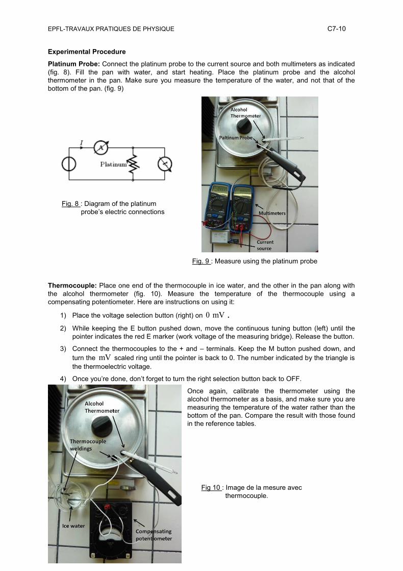
Experimental Procedure
Platinum Probe: Connect the platinum probe to the current source and both multimeters as indicated
(fig. 8). Fill the pan with water, and start heating. Place the platinum probe and the alcohol
thermometer in the pan. Make sure you measure the temperature of the water, and not that of the
bottom of the pan. (fig. 9)
Fig. 9 : Measure using the platinum probe
Thermocouple: Place one end of the thermocouple in ice water, and the other in the pan along with
the alcohol thermometer (fig. 10). Measure the temperature of the thermocouple using a
compensating potentiometer. Here are instructions on using it:
1) Place the voltage selection button (right) on 0 mV.
2) While keeping the E button pushed down, move the continuous tuning button (left) until the
pointer indicates the red E marker (work voltage of the measuring bridge). Release the button.
3) Connect the thermocouples to the + and – terminals. Keep the M button pushed down, and
turn the mV scaled ring until the pointer is back to 0. The number indicated by the triangle is
the thermoelectric voltage.
4) Once you’re done, don’t forget to turn the right selection button back to OFF.
Once again, calibrate the thermometer using the
alcohol thermometer as a basis, and make sure you are
measuring the temperature of the water rather than the
bottom of the pan. Compare the result with those found
in the reference tables.
Fig. 8 : Diagram of the platinum
probe’s electric connections
EPFL-TRAVAUX PRATIQUES DE PHYSIQUE C7-11
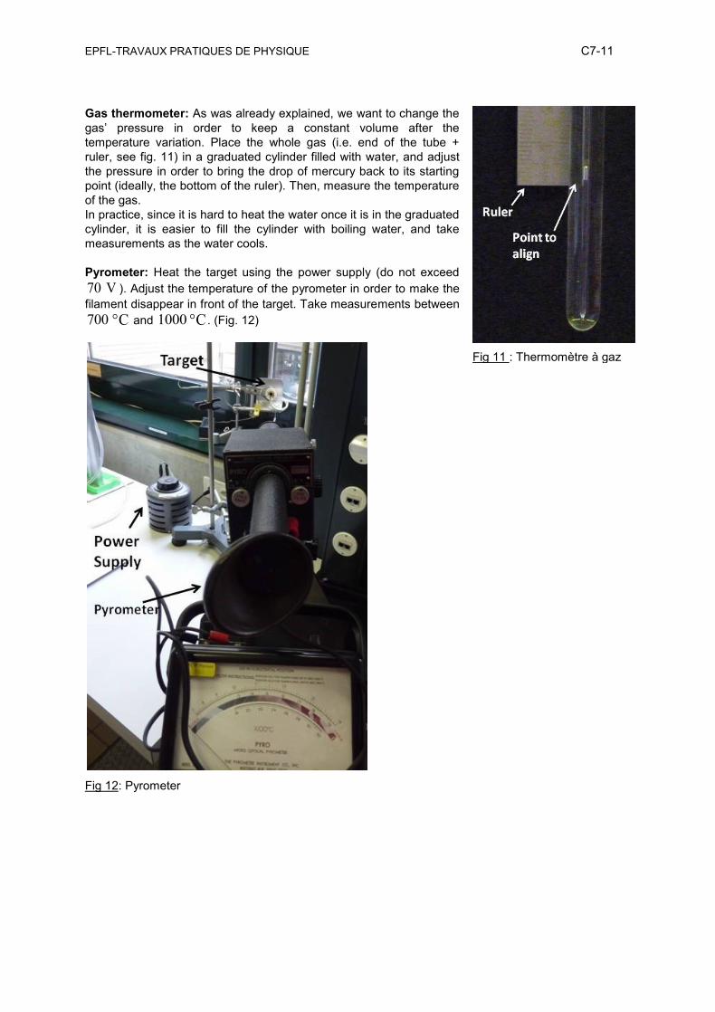
Fig 11 : Thermomètre à gaz
Gas thermometer: As was already explained, we want to change the
gas’ pressure in order to keep a constant volume after the
temperature variation. Place the whole gas (i.e. end of the tube +
ruler, see fig. 11) in a graduated cylinder filled with water, and adjust
the pressure in order to bring the drop of mercury back to its starting
point (ideally, the bottom of the ruler). Then, measure the temperature
of the gas.
In practice, since it is hard to heat the water once it is in the graduated
cylinder, it is easier to fill the cylinder with boiling water, and take
measurements as the water cools.
Pyrometer: Heat the target using the power supply (do not exceed
70 V ). Adjust the temperature of the pyrometer in order to make the
filament disappear in front of the target. Take measurements between
700 °C and 1000 °C . (Fig. 12)
Fig 12: Pyrometer