Embed Size (px)
Citation preview

INTERNATIONAL ATOMIC ENERGY AGENCYVIENNA
ISBN 978–92 –0–100409–3ISSN 1020–525X
“The IAEA’s standards have become a key element of the global safety regime for the beneficial uses of nuclear and radiation related technologies.
“IAEA safety standards are being applied in nuclear power generation as well as in medicine, industry, agriculture, research and education to ensure the proper protection of people and the environment.”
Mohamed ElBaradeiIAEA Director General
Safety through international standardsIAEA Safety Standards
Evaluation of Seismic Safety for Existing Nuclear Installations
for protecting people and the environment
No. NS-G-2.13Safety Guide
84 pages, 5.3mm
P1379_covI-IV.indd 1 2009-05-22 14:24:19
EVALUATION OFSEISMIC SAFETY FOR EXISTING
NUCLEAR INSTALLATIONS
Safety standards survey The IAEA welcomes your response. Please see: http://www-ns.iaea.org/standards/feedback.htm

The following States are Members of the International Atomic Energy Agency:
AFGHANISTANALBANIAALGERIAANGOLAARGENTINAARMENIAAUSTRALIAAUSTRIAAZERBAIJANBANGLADESHBELARUSBELGIUMBELIZEBENINBOLIVIABOSNIA AND HERZEGOVINABOTSWANABRAZILBULGARIABURKINA FASOCAMEROONCANADACENTRAL AFRICAN
REPUBLICCHADCHILECHINACOLOMBIACOSTA RICACÔTE D’IVOIRECROATIACUBACYPRUSCZECH REPUBLICDEMOCRATIC REPUBLIC
OF THE CONGODENMARKDOMINICAN REPUBLICECUADOREGYPTEL SALVADORERITREAESTONIAETHIOPIAFINLANDFRANCEGABONGEORGIAGERMANYGHANAGREECE
GUATEMALAHAITIHOLY SEEHONDURASHUNGARYICELANDINDIAINDONESIAIRAN, ISLAMIC REPUBLIC OF IRAQIRELANDISRAELITALYJAMAICAJAPANJORDANKAZAKHSTANKENYAKOREA, REPUBLIC OFKUWAITKYRGYZSTANLATVIALEBANONLIBERIALIBYAN ARAB JAMAHIRIYALIECHTENSTEINLITHUANIALUXEMBOURGMADAGASCARMALAWIMALAYSIAMALIMALTAMARSHALL ISLANDSMAURITANIAMAURITIUSMEXICOMONACOMONGOLIAMONTENEGROMOROCCOMOZAMBIQUEMYANMARNAMIBIANEPAL NETHERLANDSNEW ZEALANDNICARAGUANIGERNIGERIANORWAY
OMANPAKISTANPALAUPANAMAPARAGUAYPERUPHILIPPINESPOLANDPORTUGALQATARREPUBLIC OF MOLDOVAROMANIARUSSIAN FEDERATIONSAUDI ARABIASENEGALSERBIASEYCHELLESSIERRA LEONESINGAPORESLOVAKIASLOVENIASOUTH AFRICASPAINSRI LANKASUDANSWEDENSWITZERLANDSYRIAN ARAB REPUBLICTAJIKISTANTHAILANDTHE FORMER YUGOSLAV
REPUBLIC OF MACEDONIATUNISIATURKEYUGANDAUKRAINEUNITED ARAB EMIRATESUNITED KINGDOM OF
GREAT BRITAIN AND NORTHERN IRELAND
UNITED REPUBLIC OF TANZANIA
UNITED STATES OF AMERICAURUGUAYUZBEKISTANVENEZUELAVIETNAMYEMENZAMBIAZIMBABWE
The Agency’s Statute was approved on 23 October 1956 by the Conference on the Statute othe IAEA held at United Nations Headquarters, New York; it entered into force on 29 July 1957The Headquarters of the Agency are situated in Vienna. Its principal objective is “to accelerate andenlarge the contribution of atomic energy to peace, health and prosperity throughout the world’’.
f .
IAEA SAFETY STANDARDS SERIES No. NS-G-2.13
EVALUATION OFSEISMIC SAFETY FOR EXISTING
NUCLEAR INSTALLATIONS
INTERNATIONAL ATOMIC ENERGY AGENCYVIENNA, 2009
IAEA Library Cataloguing in Publication Data
Evaluation of seismic safety for existing nuclear installations. — Vienna : International Atomic Energy Agency, 2009.
p. ; 24 cm. — (IAEA safety standards series, ISSN 1020–525X ; no. NS-G-2.13)STI/PUB/1379ISBN 978–92–0–100409–3Includes bibliographical references.
1. Nuclear power plants — Earthquake effect. 2. Nuclear facilities — Design and construction. 3. Earthquake resistant design. I. International Atomic Energy Agency. II. Series.
IAEAL 09–00577
COPYRIGHT NOTICE
All IAEA scientific and technical publications are protected by the terms of the Universal Copyright Convention as adopted in 1952 (Berne) and as revised in 1972 (Paris). The copyright has since been extended by the World Intellectual Property Organization (Geneva) to include electronic and virtual intellectual property. Permission to use whole or parts of texts contained in IAEA publications in printed or electronic form must be obtained and is usually subject to royalty agreements. Proposals for non-commercial reproductions and translations are welcomed and considered on a case-by-case basis. Enquiries should be addressed to the IAEA Publishing Section at:
Sales and Promotion, Publishing SectionInternational Atomic Energy AgencyWagramer Strasse 5P.O. Box 1001400 Vienna, Austriafax: +43 1 2600 29302tel.: +43 1 2600 22417email: [email protected] http://www.iaea.org/books
© IAEA, 2009
Printed by the IAEA in AustriaMay 2009
STI/PUB/1379

FOREWORD
by Mohamed ElBaradeiDirector General
The IAEA’s Statute authorizes the Agency to establish safety standards to protect health and minimize danger to life and property — standards which the IAEA must use in its own operations, and which a State can apply by means of its regulatory provisions for nuclear and radiation safety. A comprehensive body of safety standards under regular review, together with the IAEA’s assistance in their application, has become a key element in a global safety regime.
In the mid-1990s, a major overhaul of the IAEA’s safety standards programme was initiated, with a revised oversight committee structure and a systematic approach to updating the entire corpus of standards. The new standards that have resulted are of a high calibre and reflect best practices in Member States. With the assistance of the Commission on Safety Standards, the IAEA is working to promote the global acceptance and use of its safety standards.
Safety standards are only effective, however, if they are properly applied in practice. The IAEA’s safety services — which range in scope from engineering safety, operational safety, and radiation, transport and waste safety to regulatory matters and safety culture in organizations — assist Member States in applying the standards and appraise their effectiveness. These safety services enable valuable insights to be shared and I continue to urge all Member States to make use of them.
Regulating nuclear and radiation safety is a national responsibility, and many Member States have decided to adopt the IAEA’s safety standards for use in their national regulations. For the contracting parties to the various international safety conventions, IAEA standards provide a consistent, reliable means of ensuring the effective fulfilment of obligations under the conventions. The standards are also applied by designers, manufacturers and operators around the world to enhance nuclear and radiation safety in power generation, medicine, industry, agriculture, research and education.
The IAEA takes seriously the enduring challenge for users and regulators everywhere: that of ensuring a high level of safety in the use of nuclear materials and radiation sources around the world. Their continuing utilization for the benefit of humankind must be managed in a safe manner, and the IAEA safety standards are designed to facilitate the achievement of that goal.

.
THE IAEA SAFETY STANDARDS
BACKGROUND
Radioactivity is a natural phenomenon and natural sources of radiation are features of the environment. Radiation and radioactive substances have many beneficial applications, ranging from power generation to uses in medicine, industry and agriculture. The radiation risks to workers and the public and to the environment that may arise from these applications have to be assessed and, if necessary, controlled.
Activities such as the medical uses of radiation, the operation of nuclear installations, the production, transport and use of radioactive material, and the management of radioactive waste must therefore be subject to standards of safety.
Regulating safety is a national responsibility. However, radiation risks may transcend national borders, and international cooperation serves to promote and enhance safety globally by exchanging experience and by improving capabilities to control hazards, to prevent accidents, to respond to emergencies and to mitigate any harmful consequences.
States have an obligation of diligence and duty of care, and are expected to fulfil their national and international undertakings and obligations.
International safety standards provide support for States in meeting their obligations under general principles of international law, such as those relating to environmental protection. International safety standards also promote and assure confidence in safety and facilitate international commerce and trade.
A global nuclear safety regime is in place and is being continuously improved. IAEA safety standards, which support the implementation of binding international instruments and national safety infrastructures, are a cornerstone of this global regime. The IAEA safety standards constitute a useful tool for contracting parties to assess their performance under these international conventions.
THE IAEA SAFETY STANDARDS
The status of the IAEA safety standards derives from the IAEA’s Statute, which authorizes the IAEA to establish or adopt, in consultation and, where appropriate, in collaboration with the competent organs of the United Nations and with the specialized agencies concerned, standards of safety for protection
of health and minimization of danger to life and property, and to provide for their application.
With a view to ensuring the protection of people and the environment from harmful effects of ionizing radiation, the IAEA safety standards establish fundamental safety principles, requirements and measures to control the radiation exposure of people and the release of radioactive material to the environment, to restrict the likelihood of events that might lead to a loss of control over a nuclear reactor core, nuclear chain reaction, radioactive source or any other source of radiation, and to mitigate the consequences of such events if they were to occur. The standards apply to facilities and activities that give rise to radiation risks, including nuclear installations, the use of radiation and radioactive sources, the transport of radioactive material and the management of radioactive waste.
Safety measures and security measures1 have in common the aim of protecting human life and health and the environment. Safety measures and security measures must be designed and implemented in an integrated manner so that security measures do not compromise safety and safety measures do not compromise security.
The IAEA safety standards reflect an international consensus on what constitutes a high level of safety for protecting people and the environment from harmful effects of ionizing radiation. They are issued in the IAEA Safety Standards Series, which has three categories (see Fig. 1).
Safety FundamentalsSafety Fundamentals present the fundamental safety objective and
principles of protection and safety, and provide the basis for the safety requirements.
Safety RequirementsAn integrated and consistent set of Safety Requirements establishes the
requirements that must be met to ensure the protection of people and the environment, both now and in the future. The requirements are governed by the objective and principles of the Safety Fundamentals. If the requirements are not met, measures must be taken to reach or restore the required level of safety. The format and style of the requirements facilitate their use for the establishment, in a harmonized manner, of a national regulatory framework. The safety requirements use ‘shall’ statements together with statements of
1 See also publications issued in the IAEA Nuclear Security Series.
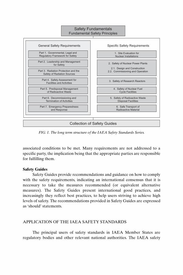
associated conditions to be met. Many requirements are not addressed to a specific party, the implication being that the appropriate parties are responsible for fulfilling them.
Safety GuidesSafety Guides provide recommendations and guidance on how to comply
with the safety requirements, indicating an international consensus that it is necessary to take the measures recommended (or equivalent alternative measures). The Safety Guides present international good practices, and increasingly they reflect best practices, to help users striving to achieve high levels of safety. The recommendations provided in Safety Guides are expressed as ‘should’ statements.
APPLICATION OF THE IAEA SAFETY STANDARDS
The principal users of safety standards in IAEA Member States are regulatory bodies and other relevant national authorities. The IAEA safety
Part 1. Governmental, Legal and
Regulatory Framework for Safety
Part 2. Leadership and Management
for Safety
Part 3. Radiation Protection and the
Safety of Radiation Sources
Part 4. Safety Assessment for
Facilities and Activities
Part 5. Predisposal Management
of Radioactive Waste
Part 6. Decommissioning and
Termination of Activities
Part 7. Emergency Preparedness
and Response
1. Site Evaluation for
Nuclear Installations
2. Safety of Nuclear Power Plants
2.1. Design and Construction
2.2. Commissioning and Operation
3. Safety of Research Reactors
4. Safety of Nuclear Fuel
Cycle Facilities
5. Safety of Radioactive Waste
Disposal Facilities
6. Safe Transport of
Radioactive Material
General Safety Requirements Specific Safety Requirements
Safety FundamentalsFundamental Safety Principles
Collection of Safety Guides
FIG. 1. The long term structure of the IAEA Safety Standards Series.
standards are also used by co-sponsoring organizations and by many organizations that design, construct and operate nuclear facilities, as well as organizations involved in the use of radiation and radioactive sources.
The IAEA safety standards are applicable, as relevant, throughout the entire lifetime of all facilities and activities — existing and new — utilized for peaceful purposes and to protective actions to reduce existing radiation risks. They can be used by States as a reference for their national regulations in respect of facilities and activities.
The IAEA’s Statute makes the safety standards binding on the IAEA in relation to its own operations and also on States in relation to IAEA assisted operations.
The IAEA safety standards also form the basis for the IAEA’s safety review services, and they are used by the IAEA in support of competence building, including the development of educational curricula and training courses.
International conventions contain requirements similar to those in the IAEA safety standards and make them binding on contracting parties. The IAEA safety standards, supplemented by international conventions, industry standards and detailed national requirements, establish a consistent basis for protecting people and the environment. There will also be some special aspects of safety that need to be assessed at the national level. For example, many of the IAEA safety standards, in particular those addressing aspects of safety in planning or design, are intended to apply primarily to new facilities and activities. The requirements established in the IAEA safety standards might not be fully met at some existing facilities that were built to earlier standards. The way in which IAEA safety standards are to be applied to such facilities is a decision for individual States.
The scientific considerations underlying the IAEA safety standards provide an objective basis for decisions concerning safety; however, decision makers must also make informed judgements and must determine how best to balance the benefits of an action or an activity against the associated radiation risks and any other detrimental impacts to which it gives rise.
DEVELOPMENT PROCESS FOR THE IAEA SAFETY STANDARDS
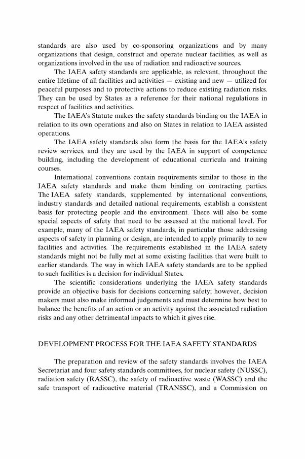
The preparation and review of the safety standards involves the IAEA Secretariat and four safety standards committees, for nuclear safety (NUSSC), radiation safety (RASSC), the safety of radioactive waste (WASSC) and the safe transport of radioactive material (TRANSSC), and a Commission on
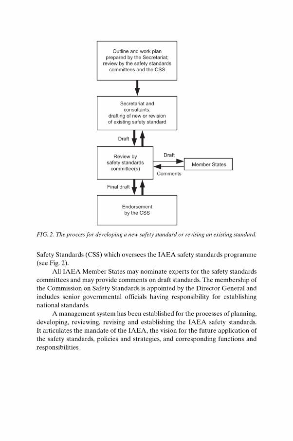
Safety Standards (CSS) which oversees the IAEA safety standards programme (see Fig. 2).
All IAEA Member States may nominate experts for the safety standards committees and may provide comments on draft standards. The membership of the Commission on Safety Standards is appointed by the Director General and includes senior governmental officials having responsibility for establishing national standards.
A management system has been established for the processes of planning, developing, reviewing, revising and establishing the IAEA safety standards. It articulates the mandate of the IAEA, the vision for the future application of the safety standards, policies and strategies, and corresponding functions and responsibilities.
Secretariat and
consultants:
drafting of new or revision
of existing safety standard
Draft
Endorsement
by the CSS
Final draft
Review by
safety standards
committee(s)Member States
Comments
Draft
Outline and work plan
prepared by the Secretariat;
review by the safety standards
committees and the CSS
FIG. 2. The process for developing a new safety standard or revising an existing standard.
INTERACTION WITH OTHER INTERNATIONAL ORGANIZATIONS
The findings of the United Nations Scientific Committee on the Effects of Atomic Radiation (UNSCEAR) and the recommendations of international expert bodies, notably the International Commission on Radiological Protection (ICRP), are taken into account in developing the IAEA safety standards. Some safety standards are developed in cooperation with other bodies in the United Nations system or other specialized agencies, including the Food and Agriculture Organization of the United Nations, the United Nations Environment Programme, the International Labour Organization, the OECD Nuclear Energy Agency, the Pan American Health Organization and the World Health Organization.
INTERPRETATION OF THE TEXT
Safety related terms are to be understood as defined in the IAEA Safety Glossary (see http://www-ns.iaea.org/standards/safety-glossary.htm). Otherwise, words are used with the spellings and meanings assigned to them in the latest edition of The Concise Oxford Dictionary. For Safety Guides, the English version of the text is the authoritative version.
The background and context of each standard in the IAEA Safety Standards Series and its objective, scope and structure are explained in Section 1, Introduction, of each publication.
Material for which there is no appropriate place in the body text (e.g. material that is subsidiary to or separate from the body text, is included in support of statements in the body text, or describes methods of calculation, procedures or limits and conditions) may be presented in appendices or annexes.
An appendix, if included, is considered to form an integral part of the safety standard. Material in an appendix has the same status as the body text, and the IAEA assumes authorship of it. Annexes and footnotes to the main text, if included, are used to provide practical examples or additional information or explanation. Annexes and footnotes are not integral parts of the main text. Annex material published by the IAEA is not necessarily issued under its authorship; material under other authorship may be presented in annexes to the safety standards. Extraneous material presented in annexes is excerpted and adapted as necessary to be generally useful.
CONTENTS
1. INTRODUCTION . . . . . . . . . . . . . . . . . . . . . . . . . . . . . . . . . . . . . . . . . 1
Background (1.1–1.6). . . . . . . . . . . . . . . . . . . . . . . . . . . . . . . . . . . . . . . . 1Objective (1.7–1.8) . . . . . . . . . . . . . . . . . . . . . . . . . . . . . . . . . . . . . . . . . . 2Scope (1.9–1.11) . . . . . . . . . . . . . . . . . . . . . . . . . . . . . . . . . . . . . . . . . . . . 3Structure (1.12). . . . . . . . . . . . . . . . . . . . . . . . . . . . . . . . . . . . . . . . . . . . . 3
2. FORMULATION OF THE PROGRAMME FOR SEISMIC SAFETY EVALUATION . . . . . . . . . . . . . . . . . . . . . . . . . . 4
General considerations (2.1–2.8) . . . . . . . . . . . . . . . . . . . . . . . . . . . . . . 4Evaluation of seismic safety (2.9–2.22) . . . . . . . . . . . . . . . . . . . . . . . . . 6Organization of the programme (2.23–2.26) . . . . . . . . . . . . . . . . . . . . 12
3. DATA COLLECTION AND INVESTIGATIONS . . . . . . . . . . . . . 13
Collection of data on existing installations (3.1) . . . . . . . . . . . . . . . . . 13Data and documentation on the original design basis (3.2–3.6) . . . . 14Current (as-is) data and information (3.7–3.13) . . . . . . . . . . . . . . . . . . 18Investigations recommended (3.14–3.23) . . . . . . . . . . . . . . . . . . . . . . . 19
4. ASSESSMENT OF SEISMIC HAZARDS (4.1–4.8) . . . . . . . . . . . . . 22
5. METHODOLOGIES FOR THE EVALUATIONOF SEISMIC SAFETY (5.1) . . . . . . . . . . . . . . . . . . . . . . . . . . . . . . . . 24
Seismic margin assessment (5.2–5.19) . . . . . . . . . . . . . . . . . . . . . . . . . . 25Seismic probabilistic safety assessment (5.20–5.31) . . . . . . . . . . . . . . . 31Common elements of the SMA and SPSA methodologies
(5.32–5.52). . . . . . . . . . . . . . . . . . . . . . . . . . . . . . . . . . . . . . . . . . . . . . . 35
6. NUCLEAR INSTALLATIONS OTHER THANPOWER PLANTS (6.1–6.15) . . . . . . . . . . . . . . . . . . . . . . . . . . . . . . . . . 42
7. CONSIDERATIONS FOR UPGRADING . . . . . . . . . . . . . . . . . . . . 46
Items to be upgraded (7.1–7.3) . . . . . . . . . . . . . . . . . . . . . . . . . . . . . . . . 46Design of modifications (7.4–7.11). . . . . . . . . . . . . . . . . . . . . . . . . . . . . 47
8. MANAGEMENT SYSTEM FOR SEISMIC SAFETYEVALUATION . . . . . . . . . . . . . . . . . . . . . . . . . . . . . . . . . . . . . . . . . . . . 48
Application of the management system (8.1–8.4) . . . . . . . . . . . . . . . . 48Documentation and records(8.5–8.7) . . . . . . . . . . . . . . . . . . . . . . . . . . 50Configuration management (8.8) . . . . . . . . . . . . . . . . . . . . . . . . . . . . . . 51
REFERENCES . . . . . . . . . . . . . . . . . . . . . . . . . . . . . . . . . . . . . . . . . . . . . . . . . 53
ANNEX: METHODOLOGIES FOR SEISMIC SAFETYEVALUATION . . . . . . . . . . . . . . . . . . . . . . . . . . . . . . . . . . . . . . 54
CONTRIBUTORS TO DRAFTING AND REVIEW . . . . . . . . . . . . . . . . 61BODIES FOR THE ENDORSEMENT OF
IAEA SAFETY STANDARDS . . . . . . . . . . . . . . . . . . . . . . . . . . . . . . 63
1. INTRODUCTION
BACKGROUND
1.1. This Safety Guide was prepared under the IAEA’s programme for safety standards. It supplements and provides recommendations on meeting the requirements for nuclear installations established in the Safety Requirements publication on Safety of Nuclear Power Plants: Operation [1]; it also relates to a number of other IAEA safety standards, including Refs [2–4].1
1.2. This Safety Guide on Evaluation of Seismic Safety for Existing Nuclear Installations complements the IAEA Safety Guide on Seismic Design and Qualification for Nuclear Power Plants [5] for the design and construction of new nuclear power plants. It provides recommendations on meeting the requirements in Ref. [1] and expands the scope to existing nuclear installations such as research reactors, nuclear fuel cycle and reprocessing facilities, and independent fuel storage facilities. Safety Reports Series No. 28 on Seismic Evaluation of Existing Nuclear Power Plants [6] provides detailed information relevant to this Safety Guide (a revision of Ref. [6] is planned).
1.3. The Safety Requirements publication on the Safety of Nuclear Power Plants: Operation [1] states that systematic safety reassessments of the plant are required to be performed by the operating organization throughout its operational lifetime. In the light of this and other requirements, as well as of the recommendations on external hazard analysis in periodic safety reviews [7], this Safety Guide addresses the seismic safety evaluation of existing installations.
1.4. Guidelines for the seismic safety evaluation of existing nuclear installations — mainly nuclear power plants — have been developed and used in many Member States.2 Since the beginning of the 1990s, these methods have been adapted to specific situations and have been applied in the seismic safety evaluation of many nuclear installations. The IAEA has assisted a number of Member States in adapting and applying these methods for installations in
1 A draft Safety Guide on seismic hazards in site evaluation for nuclear installations is in preparation, to supersede Ref. [4].
2 The development and use of guidelines on the seismic safety evaluation of existing nuclear installations started in the United States of America, where such guidelines were developed and their application to all existing nuclear power plants was required.
1
operation for which seismic safety evaluation and upgrading programmes were required and were implemented.
1.5. Seismic design and qualification is distinct from seismic safety evaluation in that seismic design and qualification of structures, systems and components (SSCs) is most often performed at the design stage of the installation, prior to its construction. Seismic safety evaluation is applied only after the installation has been constructed. Of course, exceptions exist, such as the seismic design and qualification of new or replacement components after construction of the installation. Conversely, the seismic safety evaluation for assessing beyond design basis earthquake conditions for new designs prior to construction may make use of the criteria applied for seismic safety evaluation.
1.6. Consequently, the seismic safety evaluation of existing installations strongly depends on the actual condition of the installation at the time the assessment is performed. This key condition is denoted the ‘as-is’ condition, indicating that an earthquake, when it occurs, affects the installation in its actual condition, and the response and capacity of the installation will depend on its actual physical and operating configuration. The as-is condition of the installation is the baseline for any seismic safety evaluation programme. The as-is condition includes the ‘as-built’, ‘as-operated’ and ‘as-maintained’ conditions of the installation, and its condition of ageing at the time of the assessment.
OBJECTIVE
1.7. This Safety Guide provides recommendations in relation to the seismic safety evaluation of existing nuclear installations. Such an evaluation may be prompted by a seismic hazard perceived to be greater than that originally established in the design basis, by new regulatory requirements, by new findings on the seismic vulnerability of SSCs, or by the need to demonstrate performance for beyond design basis earthquake conditions, in line and consistent with internationally recognized good practices. This Safety Guide may also be used for nuclear installations whose purpose and associated radiological risks have changed, or are proposed to be changed, and in cases where the long term operation of the installation is under consideration.
1.8. This Safety Guide is intended for use by regulatory bodies responsible for establishing regulatory requirements and by operating organizations directly responsible for the execution of the seismic safety evaluation and upgrading programmes.
2
SCOPE
1.9. This Safety Guide addresses an extended range of existing nuclear installations, as defined in Ref. [8]: land based stationary nuclear power plants, research reactors, nuclear fuel fabrication plants, enrichment plants, reprocessing facilities and independent spent fuel storage facilities. Much of the methodology is independent of the type of nuclear installation or the reactor type, but aspects such as plant performance criteria, systems modelling, etc., are specific to each installation type. The methodologies developed for nuclear power plants are also applicable to other nuclear installations through a graded approach.
1.10. For the purpose of this Safety Guide, existing nuclear installations are those installations that are either (a) at the operational stage (including long term operation and extended temporary shutdown periods) or (b) at a pre-operational stage for which the construction of structures, manufacturing, installation and/or assembly of components and systems, and commissioning activities are significantly advanced or fully completed. In existing nuclear installations that are at the operational and pre-operational stages, a change of the original design bases, such as for a new seismic hazard at the site, or a change in the regulatory requirements regarding the consideration of seismic hazard and/or seismic design of the installation, may lead to a significant impact on the design and, consequently, to important hardware modifications.
1.11. Two methodologies are discussed in detail in this Safety Guide: the deterministic approach generally represented by seismic margin assessment (SMA) and the seismic probabilistic safety assessment (SPSA). Variations of these approaches or alternative approaches may be demonstrated to be acceptable also, as discussed in Section 2.
STRUCTURE
1.12. Section 2 provides general considerations and general recommendations on the seismic safety evaluation of nuclear installations. Section 3 describes data requirements (collection and investigations). Section 4 provides recommendations on the seismic hazard assessment of the site. Section 5 details the implementation of the deterministic SMA and SPSA methodologies for the seismic safety evaluation of existing nuclear power plants. Section 6 provides recommendations on applying a graded approach to the evaluation of nuclear installations other than nuclear power plants (with reference to Section 5
3
where appropriate). Section 7 presents considerations for upgrading. Section 8 provides information on management systems to be put in place for the performance of all activities, and identifies the need for configuration management in future activities to maintain the seismic capacity as evaluated. Sections 1–4, 7 and 8, in total or in part, apply to all nuclear installations. Section 5 is specific to nuclear power plants. The Annex presents a summary of the extensive background material on methodology development and applications to date, including related references. For definitions and explanations of technical terms, see the IAEA Safety Glossary [8]. Explanations of terms specific to this Safety Guide are provided in footnotes.
2. FORMULATION OF THE PROGRAMME FOR SEISMIC SAFETY EVALUATION
GENERAL CONSIDERATIONS
2.1. It is usually recognized that well designed industrial facilities, especially nuclear power plants, have an inherent capability to resist earthquakes larger than the earthquake considered in their original design. Conservatisms are compounded through the seismic analysis and the design chain. This inherent capability or robustness — usually described in terms of the ‘seismic design margin’ — is a direct consequence of (a) the conservatism that is present in the seismic design and qualification procedures used according to previous or current practices in earthquake engineering and (b) the fact that in the design of nuclear plants the seismic loads may not be the governing loads for some SSCs.
2.2. Typically, current criteria for seismic design and qualification applicable to nuclear power plants introduce large seismic design margins; the measure of margin is frequently not specified and the amount is seldom quantified. It is known that a significant and adequate seismic design margin to failure exists and is ensured through the use of design criteria in industry standards and guidelines — particularly those applicable to nuclear installations. This has been demonstrated through the implementation of SMA or SPSA methodologies for existing nuclear power plants in several States. The introduction of the seismic design margins through the various stages of the original analysis and design leads to large expected variations throughout the
4
nuclear installation. The seismic design margin typically varies greatly from one location in the plant to another, from one structure, system or component to another, and from one location to another in the same structure. One of the main reasons for this variation, as mentioned in para. 2.1, is the fact that nuclear installations are designed for a wide range of internal and external extreme loads, for example, pressure and other environmental loads due to accident conditions, aircraft crash, tornado or pipe break, and seismic loads may not be the governing loads for some SSCs. Another reason is the method of equipment qualification in which envelope type response spectra are generally used. There should be a detailed examination of the actual design practice to understand the sources of conservatism. It should not be automatically assumed that there is excessive conservatism in the process, since this may lead to complacency in the seismic safety evaluation.
2.3. The methodologies presented in this Safety Guide are intended for evaluating and quantifying the seismic capacity of an existing installation according to the current as-is conditions.
2.4. In the seismic safety evaluation of a nuclear installation, the objective is to understand the true state of the SSCs in terms of their required safety function and their seismic capacity, and, as a result, to assess the seismic safety margin of the installation. It is therefore important to use realistic and best estimate values for the as-is condition of the SSCs and not to introduce safety factors that may unnecessarily bias the results. The approach used by the SMA methodology, for example, is to consider a higher level of seismic hazard (greater than the design ground motion) and to associate this with the realistic seismic capacity of the installation. In so doing, the inherent excess capacity of the SSCs may be taken into account.
2.5. Following the regulatory practice of the State, in either the SMA or the SPSA methodology, items other than those classified as Seismic Category I [5] that are used to prevent accidents or to mitigate accident conditions, and that were not seismically qualified in their original design basis, may be included in the programme for seismic safety evaluation; for example, existing systems that may be used in severe accident management.
2.6. The programmes for seismic safety evaluation performed for existing nuclear power plants, on the basis of the as-is condition of the installations, emphasized pragmatic evaluations rather than using extensive complex analyses. Limited non-linear analyses of relatively simple structural models or the use of higher damping values and ductility factors — provided that they are
5
used with care and are consistent with allowable deformations — may be particularly helpful in understanding post-elastic behaviour. However, detailed, sophisticated non-linear analyses are generally not undertaken in the usual practice.
2.7. Although peak ground acceleration is a parameter that is widely used to scale the seismic input, it is a known technical finding that the ability of seismic ground motions to cause damage to SSCs that behave in a ductile manner is not well correlated with the level of peak ground acceleration. It is recognized that other parameters such as velocity, displacement, duration of strong motion, spectral acceleration, power spectral density and cumulative absolute velocity should play a significant role in a judicious evaluation of the effects of seismic ground motions on SSCs. Another example is the effects caused by near field earthquakes of small magnitude (i.e. M 5.5). Most such events have high frequency content and produce high peak ground acceleration levels, but they do not generate significant damage to structures and mechanical equipment. However, if the high frequency content produced by such near field earthquakes is transmitted to the structures, it may cause operability problems with certain types of equipment. It may also affect brittle materials such as glass. Related safety concerns include spurious behaviour of electrical equipment or devices and/or of instrumentation and control systems.
2.8. With regard to the behaviour of structures, mechanical components and distribution systems, numerous field observations and research and development programmes have demonstrated that a high capacity seismic design results when the ductile behaviour of SSCs accommodates large strains, rather than when only large calculated forces are balanced, such as the forces that are usually estimated on the basis of elastic behaviour and a static equivalent approach.
EVALUATION OF SEISMIC SAFETY
Reasons for and objectives of the seismic safety evaluation
2.9. As established in the Safety Requirements publication on Safety of Nuclear Power Plants: Operation, “Systematic safety reassessments of the plant in accordance with the regulatory requirements shall be performed by the operating organization throughout its operational lifetime, with account taken of operating experience and significant new safety information from all relevant sources” (Ref. [1], para. 10.1).
6
2.10. In accordance with this requirement and in line with international practice, an evaluation of the seismic safety of an existing nuclear installation should be performed in the event of any one of the following:
(a) Evidence of a seismic hazard at the site that is greater than the design basis earthquake, arising from new or additional data (e.g. newly discovered seismogenic structures, newly installed seismological networks or new palaeoseismological evidence), new methods of seismic hazard assessment, and/or the occurrence of actual earthquakes that affect the installation;
(b) Regulatory requirements, such as the requirement for periodic safety reviews, that take into account the ‘state of knowledge’ and the actual condition of the installation;
(c) Inadequate seismic design, generally due to the vintage of the facility; (d) New technical findings, such as vulnerability of selected structures and/or
non-structural elements (e.g. masonry walls), and/or of systems or components (e.g. relays);
(e) New experience from the occurrence of actual earthquakes (e.g. better recorded ground motion data and the observed performance of SSCs);
(f) The need to address the performance of the installation for beyond design basis earthquake ground motions in order to provide confidence that there is no ‘cliff edge effect’, that is, to demonstrate that no significant failures would occur in the installation if an earthquake were to occur that was slightly greater than the design basis earthquake (Ref. [2], paras 4.6 and 5.73);
(g) A programme of long term operation of which such an evaluation is a part.
2.11. If, for the reasons above or for other reasons, a seismic safety evaluation of an existing nuclear installation is required, the purposes of the evaluation should be clearly established before the evaluation process is initiated. This is because there are significant differences among the available evaluation procedures and acceptance criteria, depending on the purpose of the evaluation. In this regard, the objectives of the seismic safety evaluation may include one or more of the following:
(a) To demonstrate the seismic safety margin beyond the original design basis earthquake and to confirm that there are no cliff edge effects.
(b) To identify weak links in the installation and its operations with respect to seismic events.
7
(c) To evaluate a group of installations (e.g. all the installations in a region or a State), to determine their relative seismic capacity and/or their risk ranking. For this purpose, similar and comparable methodologies should be adopted.
(d) To provide input for risk informed decision making.(e) To identify and prioritize possible upgrades.(f) To assess risk metrics (e.g. core damage frequency and large early release
frequency) against regulatory requirements, if any.(g) To assess plant capacity metrics (e.g. systems level and plant level
fragilities or high confidence of low probability of failure (HCLPF) values) against regulatory expectations.
2.12. The objectives of the seismic safety evaluation of an existing installation should be established in line with the regulatory requirements, and in consultation and agreement with the regulatory body. Consequently, and in accordance with such objectives, the level of seismic input motion, the methodology for capacity assessment and the acceptance criteria to be applied, including the required end products, should be defined. In particular, for evaluating seismic safety for seismic events more severe than the event specified in the original design basis, the safety objectives should include the functions required to be ensured and the failure modes to be prevented during or after the earthquake’s occurrence.
2.13. The final documentation to be produced at the end of the evaluation should be identified from the beginning in agreement with the regulatory body and should be consistent with the established purpose of the programme. The end products of these evaluations may be one or more of the following:
(a) Measures of the seismic capacity of the nuclear installation in deterministic or probabilistic terms;
(b) Identification of SSCs with low seismic capacity, and the associated consequences for plant safety, for decision making on upgrading programmes;
(c) Identification of operational modifications to improve seismic capacity; (d) Identification of improvements to housekeeping practices (e.g. storage of
maintenance equipment);(e) Identification of interactions with fire prevention and protection systems,
etc.; (f) Identification of actions to be taken before, during and after the
occurrence of an earthquake that affects the installation, including arrangements for and actions in operational and management response,
8
analysis of the obtained instrumental seismic records and performed inspections, and the integrity evaluations to be performed as a consequence;
(g) A framework to provide input to risk informed decision making.
Selection of the methodology for seismic safety evaluation
2.14. One of the first steps of the programme for seismic safety evaluation should be the selection of the methodology to be used. The objectives of the evaluation may determine the methodology to be used, the parameter values for the methodology, the use of generic data versus site specific and plant specific data, and other key elements. As indicated in the scope of this Safety Guide, two methodologies are recommended and discussed in detail: the deterministic SMA and the probabilistic SPSA. It is not intended that both methodologies be implemented, since either the SMA or the SPSA approach may satisfy the objectives of the programme. Variations of these methodologies or alternative approaches may also be demonstrated to be acceptable.
2.15. A clear distinction should be made between a seismic safety evaluation that does not entail a change in the design basis earthquake (i.e. SL-2, see Ref. [4]) and a seismic safety evaluation where a change in the design basis earthquake is required by the regulatory body. This Safety Guide focuses mainly on the methodologies for seismic safety evaluation that do not involve a change in the design basis earthquake, but that involve evaluation of the seismic safety of existing installations for seismic hazards more severe than those originally established for the design basis and a realistic determination of the available safety margin. It is clear that the agreement of the regulatory body should be obtained to define the seismic input and the acceptance criteria for this process. If current earthquake engineering methods and acceptance criteria applicable to the seismic design and qualification of new installations were used for these purposes, they would be likely to lead to significant, if not infeasible, upgrading requirements.
2.16. After selection of the evaluation methodology, the programme for seismic safety evaluation should cover the following aspects:
(a) Definition of the seismic input, that is, the earthquake ground motion parameters (see Section 4).
(b) Verification of the geological stability of the site with respect to the potential for surface faulting and use of the newly defined seismic hazard
9
(see Section 4) for the reassessment of other geological hazards (e.g. liquefaction).
(c) Seismic behaviour of the installation when subjected to the earthquake hazard, that is, the seismic demand on SSCs and their seismic capacity or fragility, systems performance, etc. Section 5 discusses these aspects.
(d) Acceptance criteria and the need for upgrading of the facility (both the installation and operations). Section 7 discusses these topics.
2.17. This Safety Guide deals with realistic failure modes of SSCs, that is, the inability of the SSCs to perform their required functions, either because of inadequate seismic capacity or due to seismic interaction. For structures, this function may be confinement, support and/or protection of other SSCs. For distribution systems and components, this function may be operability and/or fluid retention. For example, for piping systems, failure is the loss of ability to retain their flow capacity. For systems, failure is loss of acceptable performance. For structures and mechanical components, the seismic safety evaluation may permit some non-linear behaviour, but at levels lower than those allowed for conventional industrial facilities. The functions required from SSCs and the failure modes of these SSCs should be identified.
2.18. Evaluation of the seismic capacity or fragility of systems and components should rely to a significant extent on earthquake experience data and test data. There is already a significant amount of data that have been obtained, evaluated, reviewed and incorporated into procedures. These data consist of earthquake experience data and test data as follows:
(a) Earthquake experience data have been obtained from a broad range of international sources and, generally, reflect the performance of mechanical and electrical equipment and distribution systems in industrial facilities subjected to strong earthquakes.
(b) Test data are based on qualification tests or fragility tests of components. In some cases, the database of test data is dependent on component specific information, such as manufacturer, size, function and anchorage.
In all cases, the applicability of these earthquake experience data and test data should be verified with regard to the specific nuclear installation being evaluated.
2.19. The SMA methodology is based on defining a set of SSCs that, when shown to have acceptable seismic capacity, provide high confidence that the installation will successfully reach a safe state after an earthquake occurs. The identified SSCs constitute the ‘success path’. The success path for a nuclear
10
power plant, as applied in Section 5, is termed the ‘safe shutdown path’. For nuclear installations other than nuclear power plants (Section 6), success should be defined as a function of the end state to be achieved for the nuclear installation being evaluated — for example, successful confinement of nuclear material during and after the earthquake. The requirements of the success path may include considerations of defence in depth, redundancy of systems, etc., as established in agreement with the regulatory body. See also para. 5.2 and the associated footnote 3.
2.20. Plant walkdowns are an integral part of the SMA and SPSA methodologies. For all methodologies, plant walkdowns should be a key element of the programme of seismic safety evaluation. Plant walkdowns are discussed in detail in paras 5.32–5.40.
Ageing considerations
2.21. In seismic safety evaluations of nuclear installations of all types, ageing degradation should be considered. Ageing degradation includes those ageing effects that reduce the seismic capacity of SSCs. Typical ageing degradation effects include: corrosion and erosion of piping, tanks and metallic components; thermal and neutron irradiation effects (e.g. embrittlement of the reactor pressure vessel, deterioration of concrete structures, components and anchors, deterioration of electrical systems); stress corrosion cracking (for the core shroud of a boiling water reactor, primary piping, etc.); environmentally induced corrosion due to exposure to brackish water and excessive chloride concentration in the groundwater; and ageing of electrical systems and devices.
Seismic instrumentation
2.22. The seismic instrumentation installed at the site (in the free field on the surface of soil or rock, and in boreholes) and within the installation (on the foundations and at locations in the structures) should be evaluated to ensure that, if an earthquake occurs near the site, actual and reliable records will be obtained. If necessary, the seismic instrumentation should be appropriately updated or upgraded for obtaining adequate information on ground motion during and after the occurrence of an earthquake, and for determining consequent response actions for the plant, in line with current international good practices. It should also be ensured that a maintenance programme and a data communication programme for the seismic instrumentation are in place. Seismic instrumentation should be adequate to produce records for large and small earthquakes of interest.
11
ORGANIZATION OF THE PROGRAMME
2.23. A complete and detailed work plan should be prepared for the implementation of the programme for seismic safety evaluation of the installation. The operation of the installation should be taken into account in the work plan. It may not be possible to perform some of the tasks while the installation is in operation, such as collection of as-is data, performing plant walkdowns and execution of physical upgrades. The work plan should consider pending physical or operational changes so that they can be taken into account in the evaluation. A phased approach, which is a typical characteristic of seismic safety evaluation programmes, may meet these objectives.
2.24. No specific recommendations on the time schedule required for the execution of the seismic safety evaluation programme are provided in this Safety Guide. This important aspect should be defined by the operating organization with the agreement of the regulatory body, in accordance with the general ‘milestone’ schedule established for performing safety upgrades and with the available resources. If additional non-seismic upgrades are to be performed, the verification of compatibility between seismic and non-seismic upgrades should be included in the programme. The time schedule is strongly influenced by the availability of access to buildings, areas and/or equipment during both the evaluation phase (mainly in relation to the collection of data) and the upgrading phase (mainly in relation to implementation of upgrades), in consideration of the operational needs of the installation as well as the principle of optimization of radiological protection.
2.25. The successful development and completion of the programme for seismic safety evaluation require the establishment of a dedicated organization with clear responsibilities and with the necessary technical capabilities for undertaking this project. In this regard, the operating organization should establish a dedicated group (without normal operational duties) to perform the evaluation, supervised by a project manager who reports directly to the senior management of the installation.
2.26. A prioritization scheme, based on an optimal risk reduction principle, may be used to address circumstances resulting from limited resources. The programme may be divided into smaller basic tasks, while maintaining the logical technical sequence. For convenience, the evaluation process can be divided into major tasks, each of which covers several actions; for example, the following tasks may be identified:
12
(a) Compilation of the available original seismic design related information;(b) Identification and acquisition of missing as-is information;(c) Determination of the seismic hazard to be used for the evaluation;(d) For an SMA, definition of the safe shutdown procedure in the event of an
earthquake, definition of safety objectives and safety functions to be ensured, and identification of the corresponding selected set of SSCs to be evaluated;
(e) Execution of plant walkdowns for collecting as-is data, identifying weak links and problems of seismic interaction between systems and components, and screening out of SSCs from the evaluation because of their inherent and demonstrable seismic capacity;
(f) Generation of appropriate mathematical models and calculation of the seismic response of buildings and structures, including calculations for soil–structure interactions and for in-structure response spectra (floor response spectra);
(g) Evaluation of the seismic capacity of buildings and structures;(h) Evaluation of the seismic response and capacity of systems and
equipment;(i) Identification of those SSCs with inadequate seismic capacity that should
be upgraded;(j) Upgrading of those SSCs that have inadequate seismic capacity;(k) Updating, if necessary, of mathematical models, calculation of the seismic
response and verification of the seismic capacity of SSCs for the upgraded condition.
3. DATA COLLECTION AND INVESTIGATIONS
COLLECTION OF DATA ON EXISTING INSTALLATIONS
3.1. As a general feature of any seismic safety evaluation to be performed for an existing nuclear installation, the evaluation should be made by considering the state of the installation at the time the assessment is performed. This key condition of the installation is denoted the ‘as-is’ condition, indicating that an earthquake, if it occurs, affects the installation in its actual condition, and the response and capacity of the installation will depend on its actual physical and operating configuration. Consequently, one of the first and more important steps of the programme for seismic safety evaluation is to collect all the
13
necessary data and information to provide a complete representation of the actual situation of the installation. The collection of as-is data should cover those selected SSCs that will be considered within the scope of the programme for seismic safety evaluation and that have either a direct effect on system performance or an indirect effect such as by transmitting earthquake motion from one location to another. It should be also emphasized that the as-is condition should properly reflect and include the effects of ageing degradation of the installation throughout its operational lifetime. Pending physical or operational changes should also be recognized so that they can be taken into account in the evaluation.
DATA AND DOCUMENTATION ON THE ORIGINAL DESIGN BASIS
3.2. The original design basis data and documentation should be collected from all available sources. Emphasis should be put on the collection and compilation, as far as possible, of the specific data and information on the nuclear installation that were used at the design stage. Less effort and fewer resources are required for the programme for seismic safety evaluation if more complete information is collected from the design stage.
General documentation of the installation
3.3. All available general and specific documentation used at the design stage of the installation for design and licensing purposes should be compiled, including the following:
(a) The safety analysis report, preferably the final safety analysis report.(b) Codes and standards used at the time of the original design of the
installation: (i) Standards adopted and procedures originally applied to specify the
nominal properties of the materials used and their mechanical characteristics.
(ii) Standards adopted and procedures applied to define the original load combinations and to calculate the seismic design parameters.
(iii) National industry standards used for the design of structures, components, piping systems and other items, as appropriate.
(iv) National standards and procedures used for the design of conventional buildings at the time of the design of the installation, which ought to have been considered minimum requirements.
14
(c) General arrangement and layout drawings for structures, equipment and distribution systems (e.g. piping, cable trays, ventilation ducts).
(d) Results of the probabilistic safety assessment (PSA) of internal (and external) events, if performed.
(e) Data and information on results and reports of seismic qualification tests for SSCs performed during the pre-operational period, including any information available on inspection, maintenance, and non-conformance reports and corrective action reports.
(f) Quality assurance and quality control documentation with particular emphasis on the as-built conditions for materials, geometry and configuration, for assessing the modifications during construction, fabrication, assembly and commissioning, including non-conformance reports and corrective action reports. The accuracy of the data should be assessed.
Specific documentation of the SSCs included in the programmefor seismic safety evaluation
3.4. Specific information on the original design of the installation, in particular of those SSCs included in the programme for seismic safety evaluation, should be collected, as follows:
(a) System design: (i) System description documents; (ii) Safety, quality and seismic classification;(iii) Design reports;(iv) Report on confirmation of the functionality of systems; (v) Instrumentation and control, including details;
(b) Geotechnical design: (i) Excavation, structural backfill and foundation control (e.g.
settlement, heaving, dewatering); (ii) Construction of retaining walls, berms, etc.; (iii) Soil–foundation–structure failure modes and capacities (e.g.
estimated settlements, sliding, overturning, uplifting, liquefaction); (c) Structural design:
(i) Stress analysis reports for all structures of interest; (ii) Structural drawings (e.g. structural steel, reinforced and/or
prestressed concrete), preferably as-built documentation;(iii) Material properties (specified and test data);(iv) Typical details (e.g. connections);
15
(d) Component design: (i) Seismic analysis and design procedures; (ii) Seismic qualification procedures, including test specifications, test
reports, etc.;(iii) Typical anchorage requirements and types used;(iv) Stress analysis reports; (v) Pre-operational test reports, if any;
(e) Distribution system design (piping, cable trays, cable conduits, ventilation ducts): (i) Systems description documents; (ii) Piping and instrumentation diagrams;(iii) Layout and design drawings of piping and its supports;(iv) Diagrams of cable trays and cable conduits and their supports; (v) Diagrams of ventilation ducts and their supports;
(f) Service and handling equipment (although some of this is non-safety-related equipment, its evaluation may be needed for analysis and study of interaction effects in operational and storage configurations): (i) Main and secondary cranes; (ii) Refuelling machines.
Seismic design basis
3.5. The characterization of the seismic input used at the original design stage should be well understood for conducting the programme for seismic safety evaluation. Any discrepancy between the documentation of the seismic hazard assessment performed at the time of the site evaluation studies and the original design basis values finally adopted should be identified. This information is essential for determining the reference level, which will be used to assess the seismic safety margin of the installation for the new seismic input to be defined for the evaluation programme. In this regard, the following aspects should be covered:
(a) Specification of the original design earthquake level(s) as used for the design and qualification of SSCs [4].
(b) Free field ground motion parameters in terms of elastic ground response spectra, acceleration time histories or other descriptors.
(c) Dominant earthquake source parameters used to define the original seismic input motions such as magnitude (M) or intensity (I), epicentral distance (), definition and duration of strong motion, or other earthquake parameters.
16
(d) If some structures were designed in accordance with design codes whose design spectra have implicit reductions for inelastic behaviour, the corresponding elastic ground response spectra should be derived to provide a basis of comparison with the requirements of the programme for seismic safety evaluation for the newly defined seismic input.
Soil–structure interaction, structural modelling andin-structure response details
3.6. Information on soil–structure interaction analysis, modelling techniques and techniques of structural response analysis used at the time of the original design should be collected as follows:
(a) Soil–structure interaction parameters: (i) Control point location, that is, the location selected for applying the
seismic input ground motion — for example, free field surface on top of finished grade, foundation mat level or base rock level;
(ii) Soil profile properties, including soil stiffness and damping properties used in the site specific response analysis, information on the water table variation and consideration of strain dependent properties (see paras 3.14–3.17);
(iii) Method to account for uncertainties in soil properties and techniques of soil–structure interaction analysis, for example, envelope of three analyses for best estimate, lower bound and upper bound soil profiles, if used at the time of the original design;
(b) Modelling techniques: (i) Modelling techniques and analytical methods used to calculate the
seismic response of structures and the in-structure response spectra (floor response spectra);
(ii) Material and system damping, cut-off of modal damping;(iii) Allowance for inelastic behaviour, as assumed in the design phase
and as implemented during construction;(c) Structural analysis and response parameters:
(i) One or two stage analysis, using coupled or substructure models of soil and structures;
(ii) Dynamic analysis of components and structures;(iii) Eigenfrequencies and mode shapes, if available;(iv) Output of structural response (e.g. structure internal loads (forces
and moments); in-structure accelerations; deformations or displacements);
17
(v) Foundation response, including overall behaviour such as sliding or uplift;
(vi) Calculations of in-structure response spectra (floor response spectra), including: — Damping of equipment;— Enveloping and broadening criteria, if used.
CURRENT (AS-IS) DATA AND INFORMATION
3.7. After collecting as many data as is feasible in relation to the original design basis, as recommended in previous paragraphs, the present state and actual conditions of the installation (i.e. the as-is condition) should be assessed. In this regard, those persons making the assessment should proceed in a consistent and comprehensive way, properly documenting all performed steps.
3.8. If the installation has been subjected to periodic safety reviews, as recommended in Ref. [7], the reports of these reviews should be made available for the purposes of the programme for seismic safety evaluation.
3.9. A critical review of all available as-built and pre-operational documentation (reports, drawings, photographs, film records, reports of non-destructive examinations, etc.) should be performed. For this purpose, a preliminary screening walkdown should be performed to confirm the documented data and to acquire new, updated information. During this walkdown, data about any significant modifications and/or upgrading and/or repair measures that were performed over the lifetime of the installation should be collected and documented, including any reports on ageing effects. The judgement about how significant a modification would need to be in order to have an impact on the seismic response and capacity of the installation should be made by experts on the evaluation of seismic capacity.
3.10. Special attention should be paid to requirements, procedures and non-conformance reports for construction and/or assembly relating to:
(a) Excavation and backfill;(b) Field routed items (e.g. piping, cable trays, conduits, tubing);(c) Installation of non-safety-related items (e.g. masonry walls, shielding
blocks, room heaters, potable water lines and fire extinguishing lines, false ceilings);
(d) Separation distances or clearances between components;
18
(e) Field tested items;(f) Anchorages.
3.11. All records and documentation available during the operational period of the installation should be reviewed in relation to the reliability of SSCs with regard to random failures and ageing effects, as identified by in-plant inspections and operating history, including repair records and any assessment performed of the remaining lifetime. Special attention should be paid to the existence of reports on tests (if any) performed for the dynamic characterization of SSCs, as well as to inspection, maintenance and/or monitoring records.
3.12. Available information from the periodic geotechnical monitoring and geodetic survey of the site and the installation’s structures should be used for the assessment of deformations and settlements, foundation behaviour, relative displacements of structures, etc.
3.13. The seismic instrumentation installed at the site in all time periods, encompassing site selection, site evaluation, pre-operational activities and operation, may provide data to better understand and assess the specific behaviour of the soil, structures and components when subjected to real earthquakes. In this regard, all available records should be compiled and analysed. A review of the current state of seismic instrumentation and scram systems at the nuclear installation, including their operability and functionality, should be performed (see para. 2.22). The review of the existing seismic instrumentation should consider:
(a) The local seismological network at the near region around the site;(b) The seismic instrumentation at the installation itself;(c) The operating procedures established for actions required for the period
during and after the occurrence of an earthquake.
INVESTIGATIONS RECOMMENDED
Soil data
3.14. To perform reliable and realistic site specific seismic response analysis, static and dynamic material properties of soil and rock profiles should be obtained. If these data were obtained at an earlier stage (e.g. during the design
19
phase), they should be reviewed for adequacy with regard to current methodologies. In this regard:
(a) For rock layers, documentation of the rock properties for each layer is adequate.
(b) For layered soil, the strain compatible shear modulus values and damping values for each layer are the bases for the derivation of the mathematical model of the layered soil. The density and low strain properties (normally in situ measurements of P and S wave velocities, and laboratory measurements of three-axis static properties and, if possible, dynamic properties and material damping ratio) should be provided. As a function of depth, the variation of dynamic shear modulus values and damping values with increasing strain levels is needed. Strain dependent variations in soil material properties may be based on generic data if soil types are properly correlated with the generic classifications. Appropriate ranges of static and dynamic values, which account for site specific geotechnical characteristics, should be investigated and documented for use in the programme for seismic safety evaluation.
3.15. Information on the location of the local water table and its variation over a typical year should be obtained.
3.16. For the various stages of site investigation, design and construction, other data may be available from non-typical sources, such as photographs, notes and observations recorded by operations staff or others. These data should be evaluated in the light of their source and method of documentation. To the extent possible, the collection of such data should be carried out in compliance with Ref. [9].
3.17. All available information relating to actual earthquake experience at the site or at other industrial installations in the region should be obtained. Special attention should be paid to earthquake induced phenomena such as river flooding due to dam failure, coastal flooding due to tsunami, landslides and liquefaction.
Data on building structures
3.18. The as-is concrete classes used for the construction of the safety related structures should be verified on the basis of existing plant specific tests and industry standards for concrete. Either destructive or non-destructive methods may be used. The data collected, instead of the original design data, should be
20
used for further analyses and capacity evaluations. If there is significant deviation from the design values, the cause of this deviation and its consequences should be investigated.
3.19. The actual material properties of the reinforcement steel should be used in the evaluation. Material properties should be available from existing test data. If not, reliable methods of destructive and non-destructive testing should be used. The analyses of the reinforcement steel should include both mechanical properties and detailing (e.g. size of reinforcement bars, placement, geometric characteristics, concrete cover, distances between reinforcement bars). For the evaluation of the capacity of the overall structure, the properties of all significant load bearing members should be evaluated. Other cases where detailing of the reinforcement may be important include, for example, penetrations and anchorage of large components.
3.20. Although ageing effects are usually estimated in a separate project, in the seismic safety evaluation, as a minimum, the survey of a concrete building should include visual examination for cracks, effects of erosion/corrosion and surface damage, degree of carbonization, thickness of concrete cover and degree of degradation of foundation below grade due to, for example, chlorides or other corrosive contaminants present in groundwater.
3.21. A sample survey should be made to verify the geometrical characteristics of selected structure members.
3.22. An important element of the evaluation is the verification and possibly the new assessment of loads, other than seismic loads, that will be used in the seismic safety evaluation. Usually, both the dead and the live loads in the as-is condition differ from those used in the original design. The deviations should be carefully examined and documented.
Data on piping and equipment
3.23. If design information is inadequate for piping, equipment and their supporting structural systems, analysis and/or testing should be performed to establish their dynamic characteristics and behaviour. A representative sample may be sufficient.
21
4. ASSESSMENT OF SEISMIC HAZARDS
4.1. An initial step of any programme for seismic safety evaluation — in parallel with the collection of related data as indicated in Section 3 — should be to establish the seismic hazard with regard to which the seismic safety of the existing installation will be evaluated. In this regard, the seismic hazard specific to the site should be assessed in relation to three main elements:
(a) Evaluation of the geological stability of the site [4, 9], with two main objectives: (i) To verify the absence of any capable fault that could produce
differential ground displacement phenomena underneath or in the close vicinity of buildings and structures important to safety. If new evidence indicates the possibility of a capable fault in the site area or site vicinity, the fault displacement hazard should first be assessed in accordance with the guidance provided in Ref. [4]. If a clear resolution of the matter is still not possible, the fault displacement hazard should be evaluated using probabilistic methods.
(ii) To verify the absence of permanent ground displacement phenomena (i.e. liquefaction, slope instability, subsidence or collapse, etc.).
(b) Determination of the severity of the seismic ground motion at the site, that is, assessment of the vibratory ground motion parameters, taking into consideration the full scope of the seismotectonic effects at the four scales of investigation and as recommended in Ref. [4].
(c) Evaluation of other concomitant phenomena such as earthquake induced river flooding due to dam failure, coastal flooding due to tsunami, and landslides.
4.2. In general, the seismic hazard assessment may be performed using a deterministic or a probabilistic approach, depending on the objectives and requirements of the programme. In either case, both the aleatory and the epistemic uncertainties should be taken into consideration.
4.3. The evaluations recommended in paras 4.1(a) and 4.1(c) should be performed in all cases for a programme for seismic safety evaluation, regardless of the methodology used and in accordance with Refs [4, 9, 10]. For evaluating the geotechnical hazards (e.g. liquefaction, slope instability, subsidence, collapse), the new seismic hazard parameters should be used.
22
4.4. With respect to para. 4.1(b), the recommendations on assessing the seismic hazard at the site are dependent on the objectives of the evaluation. A seismic hazard assessment should be carried out as recommended in Ref. [4] when:
(a) Performing a revision of the original design basis earthquake, which may be contemplated owing to conditions such as new information about the seismic hazard at the site (e.g. a newly identified fault), the original design basis being found to be inadequate or less than the recommended minimum (e.g. as given in Refs [4–6]), or design basis ground motion characteristics differing from those originally used (e.g. a greater high frequency content for near field earthquakes);
(b) Establishing a seismic safety margin beyond the original design basis earthquake and demonstrating that there is no cliff edge effect;
(c) Performing a seismic safety evaluation in accordance with the regulatory requirements because of changes in standards or in support of long term operation (i.e. plant life extension);
(d) Performing an evaluation to verify that the newly observed performance of SSCs when subjected to a certain level of earthquake motions does not compromise the seismic capacity of the installation.
As a result of the seismic hazard assessment, a new site specific seismic hazard is defined and designated as the review level earthquake to be used for evaluation of the seismic safety of the installation.
4.5. In some cases, the regulatory body may directly specify the ground motion for which the seismic safety evaluation should be performed without an explicit seismic hazard assessment. In any case, it is recommended that a seismic hazard assessment (either deterministic or probabilistic) is performed, following the recommendations of Ref. [4], to provide valuable information for decision making in determining the review level earthquake and in interpreting the results of the evaluation.
4.6. To satisfy objectives other than those of para. 4.4, a site specific probabilistic seismic hazard assessment [4] should be performed. Typically, these objectives entail:
(a) Calculation of risk metrics (e.g. core damage frequency and large early release frequency);
(b) Establishment of a risk management tool for risk informed decision making;
23
(c) Determination of the relative risk between seismic and other internal and external hazards;
(d) Provision of a tool for cost–benefit analysis for decision making in relation to plant upgrades.
4.7. For the SMA methodology, the review level earthquake (para. 4.5) defines the seismic input that should be used in the programme of seismic safety evaluation. In this case, the review level earthquake should be defined with a sufficient margin over the original design basis earthquake to ensure plant safety and to find any ‘weak links’ that may limit the installation’s capability to safely withstand a seismic event greater than the original design basis earthquake.
4.8. For the SPSA methodology, the review level earthquake (para. 4.5) denotes the site specific probabilistic seismic hazard. Generally the results of the site specific probabilistic seismic hazard assessment include seismic hazard curves defining the annual frequency of exceedance (often referred to as the annual probability) of a ground motion parameter (e.g. peak ground acceleration), associated response spectra (e.g. uniform hazard spectra) and characteristics of the dominant source parameters (e.g. magnitude and distance from the site).
5. METHODOLOGIES FOR THE EVALUATIONOF SEISMIC SAFETY
5.1. Together with the seismic hazard assessment, as recommended in Section 4, another important initial step of any programme of seismic safety evaluation is the selection of the methodology to be used in line with the purpose of the programme, as discussed in para. 2.14. Two methodologies for performing an evaluation of the seismic capacity of a nuclear power plant are presented in this Safety Guide: (a) the deterministic SMA and (b) the probabilistic SPSA. There are many elements common to both methodologies. These common elements are discussed here, following a discussion of the unique aspects of the SMA and the SPSA methodologies.
24
SEISMIC MARGIN ASSESSMENT
5.2. The SMA methodology comprises a number of steps. One description of these steps is as follows:
(1) Selection of the assessment team; (2) Selection of the review level earthquake (see Section 4); (3) Plant familiarization and data collection (see Section 3); (4) Selection of success path(s) and of selected SSCs3; (5) Determination of the seismic response of selected SSCs for input to
capacity calculations; (6) Systems walkdown and seismic capability walkdown; (7) HCLPF determination for selected SSCs; (8) HCLPF calculations for the installation; (9) Enhancements to the programme (e.g. seismic induced fire and flood
evaluations, detailed relay reviews); (10) Peer review (see Section 8);(11) Documentation (see Section 8).
5.3. Before starting the SMA, the following aspects should be defined as part of the requirements for seismic safety evaluation as established in agreement with the regulatory body in order to define the scope of the programme:
(a) Definition of the safety functions whose fulfilment should be ensured when the installation is postulated to experience an earthquake as defined by the review level earthquake. These plant safety functions to be ensured, including the corresponding set of selected SSCs to be evaluated, are defined as the success path. One definition of the success path is safe shutdown of the plant (hot or cold shutdown) and maintaining the plant in this condition after the earthquake occurs. Safe shutdown
3 The term ‘selected SSCs’ is used in this Safety Guide to mean those SSCs that have been selected for evaluation of their seismic capacity using criteria consistent with the regulatory requirements and ultimate objectives of the seismic safety evaluation programme. This is consistent with the terminology used in Ref. [6]. In IAEA technical guidance developed in the 1990s for the seismic safety evaluation of specific nuclear power plants, the term ‘safe shutdown equipment list (SSEL)’ was also used, as borrowed from earlier usage in the United States of America. However, as the SSCs cover more than ‘equipment’ and the goals of the programme may exceed ‘safe shutdown’, the term ‘selected SSCs’ is preferred.
25
may be defined as in the original licensed design or as agreed with the regulatory body as part of the programme for seismic safety evaluation.
(b) Plant initiating conditions at the time of the earthquake. One example of initiating conditions is loss of off-site power and the unavailability of normal on-site power, such as from another nuclear power unit or a conventional power generation plant on the site, given that these would be subject to the common cause nature of the earthquake. Even though conventional power generation plants may be operational and transmission lines may be intact, the transformer substations are vulnerable to failure during earthquakes, making power unavailable to the nuclear power unit being evaluated. If power generation plants, transmission lines and substation functions are demonstrated to have HCLPF capacities (see para. 5.11) equal to or greater than those of the nuclear power unit being evaluated, availability of normal power may be taken into account.
(c) Requirements of systems to mitigate earthquake induced plant events such as loss of off-site power and small loss of coolant accidents inside the containment. As an alternative to evaluating all small lines within the containment, a practical approach is to verify that one of the success paths mitigates a small loss of coolant accident.4
(d) Redundant success paths to be considered, including assumptions concerning the availability of systems and components.
(e) Availability of outside assistance. What kind of outside assistance would be needed, and when would it be available? The type of outside assistance and the conditions for availing of outside assistance should be established and agreed with the regulatory body. For example, outside assistance may be made available either (i) immediately after earthquake induced shaking has stopped, or (ii) after a certain period of time (e.g. 24, 48 or 72 h).
5.4. The SMA assessment team should be a multidisciplinary team made up of systems engineers, operations personnel and seismic engineers with recognized expertise in the subject area. The systems engineers focus on defining front-line and support systems necessary to achieve the desired plant end state on the basis of the assumptions listed in para. 5.3. Systems and operations personnel formulate the candidate alternatives for safe shutdown and select the final preferred safe shutdown path (and an alternative path, if required) with the
4 In some Member States, a small loss of coolant accident is defined as the cumulative equivalent break size of a 25 mm diameter pipe.
26
assistance of the seismic engineers. Seismic engineers screen the selected SSCs for ruggedness and in-plant vulnerabilities, and calculate HCLPF values (see para. 5.11) for those SSCs that are included in the safe shutdown path(s). A typical assessment team has 3–5 members.
5.5. Candidate success path(s) should be selected by the systems engineers with input from operations personnel. The fundamental safety functions to be ensured when subjected to the review level earthquake should be defined as an initial step in the programme. The fundamental safety functions specified in Ref. [2], para. 4.6, are:
“(1) control of reactivity; (2) removal of heat from the core; and (3) confinement of radioactive materials and control of operational
discharges, as well as limitation of accidental releases.”
The function “removal of heat from the core” is further itemized in the SMA methodology as: control of the reactor coolant pressure, control of the reactor coolant inventory, and decay heat removal. In part, the third safety function refers to the containment and containment systems. The required monitoring and control systems should be evaluated and their acceptable performance verified.
5.6. In the SMA methodology, the objective of determining the seismic response of the selected SSCs should be to generate seismic responses by using median centred procedures and parameter values, with the end result being deterministic median centred seismic responses to the review level earthquake (see Ref. [6] for details). Median centred response values are appropriate in the evaluation of margins.
5.7. The seismic response of those buildings and structures selected as part of the safe shutdown path should be determined for use in:
(a) Evaluation of the structural capacity on the basis of the function to be maintained and the damage mode;
(b) Generation of the seismic input motions for systems and components (typically, in-structure response spectra or floor response spectra).
Similarly, determination of the seismic response of systems and components is important for calculating the HCLPF capacity of these items.
27
5.8. Scaling, analysis (deterministic or probabilistic) or testing should be used for determining the seismic response. Scaling of the calculated responses for the seismic design is most appropriate for rock sites and is applicable when the seismic design models are judged to be approximately median centred (i.e. without bias). Deterministic analyses, including provisions to account for uncertainties in analytical procedures and parameter values, are also acceptable. Probabilistic methods of analysis are the most realistic because of the explicit treatment of uncertainties in the process.
5.9. The systems walkdown is aimed at reviewing preliminary success path(s), and it should be performed by an assessment team that, as indicated in para. 5.4, includes systems engineers, operations personnel and seismic engineers. Operations personnel should ensure that the selected paths are compatible with plant operating procedures. Seismic engineers should review the candidate SSCs for robustness and for ease of demonstrating high capacities. This latter review includes the SSCs and the immediate surrounding areas for the purpose of considering potential sources of failure of SSCs due to the effects of seismic induced system interactions. The end result of the systems walkdown is the selection of the final success path(s) and the set of selected SSCs to be evaluated.
5.10. A seismic capability walkdown, or plant walkdown, should be performed as the next step. The plant walkdown is discussed in detail in paras 5.32–5.40.
5.11. For the SMA methodology, the seismic capacities of the selected SSCs may be defined as HCLPF capacities5. The HCLPF capacity of an SSC is the earthquake motion level at which there is a high confidence (about 95%) of a low (5%) probability of failure. Frequency characteristics of this earthquake motion are described by the frequency characteristics of the review level earthquake. Although defined conceptually in a probabilistic sense, HCLPF
5 HCLPF capacity is the earthquake motion level at which there is a high confidence of a low probability of failure. HCLPF capacity is a measure of seismic margin. In seismic PSA, this is defined as the level of earthquake ground motion at which there is a high (95%) confidence of a low (at most 5%) probability of failure. Using the log-normal fragility model, the HCLPF capacity is expressed as Am e[–1.65(r+u)]. When the logarithmic standard deviation of composite variability c is used, the HCLPF capacity can be approximated by the ground motion level at which the composite probability of failure is at most 1%. In this case, the HCLPF capacity is expressed as Am e[-2.33c]. In deterministic SMAs, the HCLPF is calculated using the conservative deterministic failure margin method.
28
values may be calculated by deterministic methods. See the Annex for a more detailed explanation of methodologies for seismic safety evaluation, including HCLPF.
5.12. The calculations of the HCLPF (for the selected SSCs and for the plant) should be performed by the seismic engineers and should be properly documented. As a result of these calculations, the selected SSCs should be classified as follows:
(a) Selected SSCs evaluated to be ‘seismically robust’, with HCLPF capacities above the review level earthquake. This evaluation is carried out using: (i) screening tables, such as those developed on the basis of earthquake experience data and numerous calculations of the failure of SSCs; (ii) in-office verification that the conditions of the screening (also referred to as caveats) are met; and (iii) in-plant verification of as-built conditions and the absence of any local hazards such as sources of system interactions.
(b) Selected SSC items grouped by similar type or characteristics, and HCLPF calculations performed to envelop the conditions of the items of the group.
(c) Selected SSCs for which specific HCLPF calculations are performed and which do not fit in either of the two categories above.
5.13. The HCLPF capacity of a success path should be assumed to be equal to the HCLPF for the item with the lowest HCLPF capacity in the path. For seismic safety evaluations with requirements for a single success path, this will be the plant HCLPF capacity; for seismic safety evaluations with requirements for multiple success paths to be evaluated, the plant HCLPF capacity may be defined as the success path with the highest HCLPF value.
5.14. Depending on the final objectives of the evaluation, the regulatory body and the operating organization should consider aspects such as: (a) alternative or multiple success paths; (b) analysis of non-seismic failures and human actions; (c) evaluation of the containment and containment systems; and (d) relay chatter evaluation, within the SMA.
5.15. The underlying concept of alternative redundant success paths is that multiple success paths, including front-line and support systems, should be selected to include diversity in the systems, piping runs and components to the extent possible. If two success paths are selected, one is denoted primary and the other is denoted alternative. The primary success path should be the path
29
for which it is judged to be the easiest to demonstrate a high seismic safety margin, and one that the operators would employ after a large earthquake (i.e. consistent with plant operational procedures) and for which training has been performed. The alternative path should comprise differing operational sequences, systems and components to the extent possible.
5.16. A detailed walkdown inside the containment to verify that all small lines can withstand the review level earthquake, including the assessment of seismic spatial interactions resulting in the failure of small lines, is resource intensive and may lead to excessive radiation exposure of the walkdown team. An alternative to a detailed walkdown inside the containment is to require that one of the two success paths be capable of sustaining concurrently the loss of off-site power and small loss of coolant accidents inside the containment.
5.17. The consideration of non-seismic failures, that is, random failures and system outages for other reasons such as maintenance as well as human errors, should be taken into account. In selecting the success paths, random failures, as they pertain to the functions to be performed by the systems, should be evaluated. The use of success paths that rely on SSCs with high random failure rates when called upon to perform the function necessary to the success path should be avoided to the extent possible.
5.18. The actions required of the staff should be evaluated in the light of the common cause nature of the earthquake event in order to ensure that the functions of the success paths are performed. Operations staff should be aware of the required timing of actions, their duration, potential interference with other responsibilities, etc. If the operations staff are required to move to different locations in the plant after the occurrence of an earthquake, the paths to these locations should be evaluated with respect to the consequences of the earthquake, such as damage to structures that are not seismically qualified, to avoid any impediments to physical access that might affect human performance.
5.19. Typically, a review of the confinement function may be required by the regulatory body and/or desired by the operating organization. If required, vulnerabilities leading to early failure of the containment and containment systems should be reviewed and evaluated in the same manner as the success paths and HCLPFs were developed for the plant safe shutdown state. Walkdowns of the containment systems may take place concurrently with the walkdowns of other systems or may be scheduled separately, depending on accessibility. Items such as penetrations, equipment hatches and personnel
30
hatches, impacts between buildings, and containment systems should be reviewed. HCLPFs should be developed and the capacity of the containment should be documented.
SEISMIC PROBABILISTIC SAFETY ASSESSMENT
5.20. The SPSA methodology has evolved over the past three decades following the development of PSA methodologies for internal events. The SPSA methodology comprises a number of steps. In general, an SPSA should include:
(1) Selection of the assessment team;(2) Seismic hazard assessment (see Section 4); (3) Plant familiarization and data collection (see Section 3); (4) Systems analysis and accident sequence analysis leading to event tree and
fault tree modelling and identification of the selected SSCs;(5) Determination of the seismic response of structures for input to fragility
calculations;(6) Human reliability analysis for seismic events;(7) Walkdowns for seismic capability; (8) Fragility calculations for the selected SSCs; (9) Risk quantification for the installation; (10) Enhancements to the programme (e.g. seismic induced fire and flood
evaluations, detailed relay reviews); (11) Peer review (see Section 8);(12) Documentation (see Section 8).
5.21. The event trees and fault trees for the SPSA should be based on these internal event system models, with modifications and additions for treating seismically induced failures that are not considered in the internal event case. The SPSA differs from an internal event PSA in several important ways that should be taken into consideration:
(a) Earthquakes are common cause events that simultaneously affect all elements of the plant and the surrounding area.
(b) For a site with multiple installations (nuclear and non-nuclear), the combined consequences for all installations are important.
(c) Earthquakes may cause initiating events different from those considered in an internal event PSA.
31
(d) The range of earthquakes, from small to very large, causes a wide spectrum of demands on SSCs (e.g. earthquakes in the near field and distant earthquakes, earthquakes of varying magnitudes and of different types of seismogenic source, and earthquakes in different regions) [4].
(e) The risk is quantified, that is, integration of risks over the seismic hazard is performed. The lower limit of the integration is defined at slightly below the level used for the design of the installation, unless it can be demonstrated by means of the fragilities of selected SSCs that contributions to plant risk are likely from lower level earthquakes.
(f) Failure modes of passive SSCs, that is, items such as structures, structural components, piping and other items that would probably not be included in an internal event PSA, are included.
5.22. The SPSA end products should be derived from the model and the modelling process, and should include quantitative end metrics such as the core damage frequency and, if required, the large early release frequency. Frequently, failure of containment or containment bypass may serve as a surrogate for the large early release frequency. These end products should include:
(a) Understanding of accident behaviour; (b) Understanding of the most likely accident scenarios induced by
earthquakes; (c) Identification of dominant seismic risk contributors: components,
systems, sequences and procedures; (d) A list of seismic fragilities of selected SSCs and seismic margins as
defined by HCLPF values; (e) Identification of the range of earthquakes that contribute most
significantly to the seismic risk; (f) Calculation of seismic risk defined by core damage frequency or large
early release frequency as point estimates and as probability distributions represented by confidence intervals;
(g) Comparison of seismic risk with risks arising from other events (e.g. internal events, fires);
(h) Identification of the importance of non-seismic failures (e.g. failure of diesel generators to start on demand);
(i) Identification of operator actions required to achieve success; (j) Identification of potential modifications to the installation (physical and
operational) and of the surrounding area (physical and administrative), and quantification of related risk reductions.
32
5.23. The SPSA assessment team should comprise: staff with expertise in seismic hazard analysis; staff familiar with the internal event PSA (systems engineers, operations engineers, and others involved in the development and use of the internal event PSA model); experts in the area of fragility function development; and the engineering staff of the operating organization.
5.24. The system models of the internal event PSA should be modified for initiating events and for the responding system behaviour, that is, the front-line and support systems that are called into action to prevent the progression of the initiating event to core damage or to other undesirable end states. If new initiating events due to earthquakes are identified (i.e. if they were not included in the internal event PSA), new event trees and, possibly, new fault trees should be developed. In all cases, event trees and fault trees should be modified to account for seismic induced failures, that is, by adding basic events that represent the failure of SSCs due to seismic loading conditions. On the basis of a combination of engineering assessments and judgement, the experts of the assessment team should act to limit the number of initiating events to those that are credible. Fragility functions, as discussed in the following paragraphs, should be derived for the SSC failure modes identified by fragility analysts. System models representing the containment systems should be appended to the sequences leading to core damage, where required.
5.25. In the SPSA methodology, the objective of determining the seismic response of SSCs should be to generate the seismic response by using median centred procedures and parameter values. Median centred values of seismic response should be calculated as a function of the earthquake excitation level. The end result is the seismic response represented by a probability distribution, usually assumed to be log-normal.
5.26. Seismic responses may be determined by scaling the design seismic response values to account for conservatisms in the design calculations, or by reanalysis of the structures of interest or reanalysis of a representative subset.
5.27. The plant walkdown is an essential part of the SPSA methodology and should be performed in accordance with the guidance provided in paras 5.32–5.40.
5.28. The fragility assessment parallels the approach of the HCLPF calculation described in para. 5.11 for the SMA methodology. An important distinction is that the starting point for the SPSA is a set of SSCs that is significantly larger than that of the success path(s) of the SMA. This set should be appropriately
33
reduced by screening the components on the basis of their high seismic capacity, the lack of seismically induced failures due to system interactions (verified in the plant walkdown), and the level of seismic demand to which they are subjected at high levels of earthquake ground motion. The SSCs screened out using this approach should be replaced in the system models by a surrogate element of high capacity (or low fragility). The screening level and associated value of the fragility surrogate element should be established such that the surrogate element is not a dominant contributor to the end metrics. The end result is a list of selected SSCs for which further evaluation should be performed.
5.29. Fragility functions should be developed for items in the list of selected SSCs for which further evaluation should be performed, resulting from the screening process described in para. 5.28 above. The fragility function should relate the probability of failure of SSCs to a measure of the seismic loading. Fragility functions should be developed for the controlling failure mode or for multiple failure modes. Fragility functions should be directly related to the functional requirements of the selected SSCs. The measure of loading may be a ground motion parameter (most often peak ground acceleration or average spectral acceleration over a range of frequencies) or a local response parameter (in-structure response spectra, force quantity, etc). The fragility function should represent the median value as well as the associated uncertainties due to inherent randomness — that is, aleatory uncertainties — and due to the state of knowledge (or modelling) — that is, epistemic uncertainties.
5.30. Risk quantification should result from combining the system models with the fragility functions and integrating over the seismic hazard. Alternatively, the risk quantification can be associated with each group of seismic initiating events or with a particular ground motion level. The end metrics of core damage frequency and large early release frequency (or confinement functional failure) should be calculated as point estimates or as distributions, depending on the needs of the project and the level of detail of the data elements.
5.31. Depending on the final objective of the evaluation, the regulatory body and the operating organization should consider aspects such as:
(a) Analysis of non-seismic failures. The analysis of non-seismic failures is treated easily in the SPSA, since the system models are derived from the internal event models, which were developed to represent non-seismic failures. Those SSCs having low non-seismic reliability should be included
34
in the quantification of risk, and their effects on the end metrics may be quantified with sensitivity studies.
(b) Global behaviour of structures such as uplift, drift, overturning and settlement, and the modelling of these in the PSA (e.g. singletons).
(c) Human actions (see para. 5.18).(d) Evaluation of the containment and containment systems (see para. 5.19),
including fragility functions developed (HCLPF values). (e) Evaluation of electrical devices (see para. 5.48). (f) Evaluation of interactions due to seismically induced fire and seismically
induced flooding.
COMMON ELEMENTS OF THE SMA AND SPSA METHODOLOGIES
Plant walkdown
5.32. The term ‘selected SSCs’ denotes those SSCs that are of interest for the purposes of the SMA or SPSA; the equipment of the selected SSCs is typically documented on the list of safe shutdown equipment for the SMA or the list of seismic equipment for the SPSA.6
5.33. Plant walkdowns are one of the most significant components of the seismic safety evaluation of existing installations, for both the SMA and the SPSA methodologies. Plant walkdowns should be performed within the scope of the seismic safety evaluation programme. The term ‘plant walkdown’ is used here to denote the ‘seismic capability walkdown’ for the SMA approach and the ‘fragility walkdown’ for the SPSA approach. These walkdowns may serve many purposes, such as: gathering and verifying as-is data; verifying the screening-out of SSCs due to high capacities on the basis of engineering judgement; verifying the selection of safe shutdown paths for the SMA; evaluating in-plant vulnerabilities of SSCs, specifically issues of seismic system interaction (impact, falling, spray, flooding); identifying other in-plant hazards, such as those related to temporary equipment (scaffolding, ladders, equipment carts, etc.); and identifying the ‘easy fixes’ that are necessary to reduce some obvious vulnerabilities, including interaction effects. Walkdowns should also be used to consider outage configurations that are associated with shutdown modes. Detailed guidance on how to organize, conduct and document
6 See footnote 3 on p. 25.
35
walkdowns should be developed or adapted from existing walkdown procedures.
5.34. The plant walkdown should include the following:
(a) Preparatory activities for the walkdown (in the office); (b) Preliminary walkdown of the selected SSCs;(c) Walkdown plan; (d) Detailed walkdown; (e) Documentation.
5.35. Preparation for the walkdown is an office activity. It should include:
(a) Plant familiarization (Section 3). (b) Review of the selected SSCs identified by systems analysts; making a
preliminary grouping of items and specifying the appropriate level of detail for capacity evaluation; confirming with systems analysts the completeness of the list.
(c) Performing a first screening of items on the basis of their robust seismic capacity, for example, using screening rules for the seismic capacity.
(d) Assembling a database of selected SSCs that includes the name, component type, manufacturer, size, anchorage, design conditions, function, physical location and any other appropriate information on the SSCs, and that is available in the office. Typically, these data include a summary listing (of selected SSCs) and individual packages of information called ‘seismic safety evaluation worksheets’. This incomplete listing of data will be supplemented in the field in the in-plant evaluation and by means of calculations of HCLPF values or fragility functions upon completion of the project.
(e) Determining requirements for access, such as access for training, for escorting, for maintenance of equipment, etc.
(f) Preparing a preliminary walkdown plan for selected SSCs.
5.36. For the preliminary walkdown of selected SSCs, the selected SSCs that are accessible should be visually examined. The walkdown should include:
(a) Determining the location and accessibility of each item of the selected SSCs; identifying the need for operations or maintenance support to access particular components (e.g. to open electrical equipment to verify the device support and the overall anchorage); completing seismic safety evaluation worksheets and data sheets to the extent possible;
36
(b) Identifying groups of components for which a bounding sample may be evaluated to represent the group (e.g. motor controlled valves);
(c) Verifying the in-office screening for robustness, including any caveats; verifying that seismic system interactions will not impair the component’s ability to perform its designated function;
(d) Verifying the feasibility of proposed easy fixes and identifying other candidate easy fixes;
(e) Confirming the walkdown plan for the detailed walkdown.
5.37. Detailed walkdowns should entail an in-plant evaluation of selected SSCs for which robustness screening was not applicable or for which robustness was not verified during the previous preliminary walkdown, and for items requiring an HCLPF or a calculation of fragility function. All field information required as input to the calculation of HCLPF values or fragility functions will be gathered. The data documentation initiated in the pre-walkdown phase (see para. 5.35) should be completed. Documentation of this task should be in the form of drawings, field notes, photographs, videos, etc.
5.38. Each walkdown team should include qualified seismic engineers, with plant support as required (maintenance, operations, systems and engineering). The seismic engineers should have sufficient experience in the seismic analysis, design and qualification of SSCs for resisting earthquakes and other loads arising from normal operations, accidents and external events. At least one team member should be familiar with the design and operation of the SSC being walked down. Support in several technical disciplines such as from the mechanical, electrical and instrumentation and control departments may be required.
5.39. The walkdown should also be aimed at identifying spatial interactions, which have the potential to adversely affect the performance of the selected SSCs. The following are major issues of seismic system interactions that should be addressed:
(a) Falling interaction is a failure of the structural integrity of a non-safety-related item or a safety related item that can impact on and damage one or more selected SSCs. For the interaction to be a threat to selected SSCs, the impacts would have to transfer considerable energy, and the target would have to be vulnerable. A light fixture falling on a 10 cm diameter pipe may not be a credible damaging interaction with the pipe. However, such a light fixture falling on an open relay panel is an interaction that should be addressed. Unreinforced masonry walls are among the most
37
common causes of falling interactions. Masonry walls may be in close enough proximity that their failure could damage safety related equipment within the enclosure bounded by them.
(b) Proximity interactions are defined as conditions in which two or more items are in close enough proximity that any unsafe behaviour of one of them may have consequences for the other. The most common example of a proximity interaction is the impact of an electrical cabinet containing sensitive relays with adjacent items.
(c) Spray and flooding can result from the failure of piping systems or vessels that are not properly supported or anchored. Inadvertent spray hazards to selected SSCs arise most often from wet piping systems for fire protection. Impact and fracture or leakage of sprinkler heads is the most common source of spray. If spray sources can spray equipment sensitive to water spray, then the source should be backfitted, usually by adding support to reduce deflections and impacts or stresses. Large tanks may be potential flood sources. If a flood source can fail, the walkdown team, with the assistance of plant personnel, should assess the potential consequences, taking into account the flow paths and dispersion of liquid through penetrations, drains, etc.
5.40. As a key activity of the programme for seismic safety evaluation, the walkdown should be properly documented as follows:
(a) A summary walkdown report may be written to summarize system wide issues, if any, and to provide a high level summary.
(b) A summary listing of the selected SSCs with relevant data should be produced.
(c) At the most detailed level, walkdown packages for each item in the listing of selected SSCs should be produced. These walkdown packages include a summary sheet and backup information (e.g. walkdown notes, photographs, drawings, calculations). These packages should be made available to the peer review team. The packages may also include HCLPF or fragility function calculations. However, calculation packages for the HCLPF or fragility function may be filed separately, with cross-referencing of the walkdown package.
Buildings and structures
5.41. For each building and structure defined as part of the selected SSCs, the function to be maintained, the damage mode for the function and the indicator for the damage mode should be defined. For the shear wall structures generally
38
used in nuclear power plants, the shear strain of each level (inter-storey drift) of the shear wall corresponds to this indicator.
5.42. The evaluation procedure for the best estimate of seismic response should be defined, in accordance with the function and damage mode of the building and structure. Procedures for response calculation, such as scaling or analysis, should be selected (linear, equivalent linear or non-linear, etc.; see Ref. [6] for details). Dynamic testing of existing buildings and structures (using environmental vibrations, impact and/or impulsive loads, dynamic mechanical actuators, etc.) may also provide useful as-is data for characterizing their dynamic properties and estimating realistic seismic responses.
Equipment–building interface
5.43. Equipment–building interfaces consist of anchorages, for example, welds to embedded plates and substructures, and anchor bolts, which attach equipment to the substructures of the structure itself. Evaluation of equipment–building interfaces should be included in the evaluation of equipment and piping in SMAs and SPSAs. All dominant failure modes of these interfaces, such as failure of the anchorage or failure of the substructure (concrete, steel, etc.), should be identified and evaluated on the basis of the as-is conditions. The expected behaviour of the supporting substructure during the earthquake should also be taken into account, for example, concrete cracking, which may also result in a capacity reduction of the expansion anchor bolts.
Distribution systems
5.44. Evaluation of distribution systems (such as piping, cable trays, conduits, heating, ventilation and air conditioning) should be included in the SMA and SPSA methodologies on the basis of the design information, plant walkdowns, sample calculations and testing, if available. Failure modes should be related to functional failure. For distribution systems, plant walkdowns should be performed on an area by area basis and not by individual line. The seismic capability engineers should look for situations such as overloaded cable trays and for system interaction hazards.
Primary reactor system
5.45. A realistic evaluation of the seismic capacity and seismic safety margin of the primary reactor system should be performed. A global model including soil, supporting structure and primary system may be used to account for dynamic
39
coupling and to generate input motions at the support points of the primary system for its detailed evaluation.
Equipment
5.46. The HCLPF value or the fragility function for an item of equipment should relate failure of the equipment to perform its required function to the seismic input to the equipment item. It should be recognized that some damage to the equipment may be tolerated as long as the equipment item can perform its function. The required function includes the time period for which the function is required, for example, the time period for which the item is required to operate during and/or after the earthquake induced shaking, and the required duration of operation without outside support.
5.47. All installation specific information on seismic design and qualification should be used in the determination of the HCLPF value or fragility function. Installation specific data should be supplemented by earthquake experience data and generic evaluation results (from analyses or tests) when these are demonstrated to be applicable. Data from shake table tests are generally required to demonstrate active equipment operability during the earthquake induced shaking. Data from seismic qualification tests may be extrapolated for the development of the HCLPF value or fragility function. Recovery actions may be considered if required to demonstrate higher HCLPF values or lower fragility functions. It should be verified that recovery actions are achievable in the event of an earthquake.
Review of electrical devices
5.48. Malfunctioning of electrical devices, such as relay or contact chatter, is a phenomenon associated with vibrations whereby a device may change position or state, or may send spurious signals. Relay chatter is often observed in functional tests. A systematic review of electrical devices should be performed, and the results should be taken into account in the SMA or SPSA methodologies. The review should include the following steps:
(a) Identification of the devices associated with the success paths for the SMA or important systems for the SPSA;
(b) Assessment of the consequences of the malfunctioning of devices for the system involved;
(c) Capacity or fragility evaluation.
40
Seismic induced fire and flood
5.49. Seismic safety reviews should include seismic induced events such as fire and flood. Such reviews should be performed by a team that comprises seismic engineers and fire engineers, in particular those who have been involved in the evaluation of the installation’s fire risk analysis. These reviews should be performed principally by means of plant walkdowns focused on area reviews, that is, the review for ignition sources and combustibles in areas or compartments containing components important to the success path or the SPSA. Ignition sources are those potentially initiated by the earthquake induced shaking. Combustibles in the area where ignition occurs and in adjoining areas should be reviewed with respect to fire protection and possible fire spread due to the failure of boundaries. Potential impacts on the success paths chosen (for SMA) and on the risk quantification (for SPSA) should be incorporated into the evaluations and should be adequately documented.
5.50. Experience from past earthquakes has demonstrated that numerous configurations of fluid retaining components are susceptible to damage from earthquake induced shaking. Examples include unanchored tanks, non-ductile piping, mechanical couplings for piping systems (fire protection systems) and sprinkler heads for wet systems. The need to review local sources of spray and flooding when evaluating items on the list of selected SSCs is discussed in paras 5.32–5.40 on plant walkdown. Overall area walkdowns covering buildings and yards should be performed to evaluate other sources of flooding, for example, sloshing of water in spent fuel pools, failure of tanks at higher elevations in a building with flow paths available through penetrations in the floor and failure of yard tanks with flow paths available to building levels below ground level. A further specific evaluation should cover inadvertent actuation of the fire protection system. Potential impacts on the success paths chosen (for SMA) and on the risk quantification (for SPSA) should be incorporated into the evaluations.
5.51. Influences of tsunami hazards on the safety functions of nuclear installations located near coastlines, for example, the malfunctioning of equipment located at a low level, such as seawater pumps, should be evaluated according to Refs [10, 11].
Evaluation of soil capacity
5.52. Soil failure modes may be important and should be considered. These modes should include soil failure itself (e.g. slope instability, settlement, loss of
41
bearing capacity, liquefaction) and failure modes including structures (i.e. structure sliding, uplift and overturning); see Ref. [9]. The essential aspect that should be considered for potential soil failures is their impact, direct or indirect, on selected SSCs. For example, large relative displacements of structures induced by excessive deformations of the foundation soil may have significant adverse effects on interconnecting distribution systems, such as piping and conduits. Soil failure modes encompass the effect of potential fault displacements on the site and structures (para. 4.1(a)(i)). The fault displacement hazard and its consequences should be treated using probabilistic approaches for evaluating the seismic safety of existing installations.
6. NUCLEAR INSTALLATIONSOTHER THAN POWER PLANTS
6.1. This section provides guidance on the seismic safety evaluation of a broad range of nuclear installations other than nuclear power plants. These installations include [8]:
(a) Research reactors and laboratories handling nuclear material;(b) Installations for storage of spent nuclear fuel (collocated with either
nuclear power plants or independent installations), including:— Installations for spent fuel storage for which active cooling is required;— Installations for spent fuel storage that require only passive or natural
convection cooling;(c) Processing facilities for nuclear material in the nuclear fuel cycle (e.g.
conversion facilities, uranium enrichment facilities, fuel fabrication facilities, reprocessing plants).
6.2. For the purpose of seismic safety evaluation, these installations should be graded on the basis of their complexity, potential radiological hazards and hazards due to other materials present. Seismic safety evaluation should be performed in accordance with this grading. SSCs in these installations should be evaluated in accordance with their importance to achieving safe shutdown or other defined successful end states.
6.3. Prior to categorizing an installation, a conservative screening process should be applied in which it is assumed that the complete radioactive
42
inventory of the installation is released by the seismically initiated accident. If the result of this release is that no unacceptable consequences would be likely for workers or for the public (i.e. doses to workers or to the public due to the release of that inventory would be below the limits established by the regulatory body), or for the environment, and no other specific requirements are imposed by the regulatory body for such an installation, the installation may be screened out from the seismic safety evaluation. If, even after such screening, some level of seismic safety evaluation is desired, national seismic codes for commercial/industrial facilities may be used.
6.4. If the results of the conservative screening process show that the consequences of the releases are ‘significant’, a seismic safety evaluation of the installation should be carried out.
6.5. The seismic hazard at the site should be evaluated in accordance with the methodology presented in Section 4, or on the basis of national seismic hazard maps, as applicable.
6.6. The likelihood that a seismic event will give rise to radiological consequences depends on the characteristics of the nuclear installation (e.g. its use, design, construction, operation and layout) and on the event itself. Such characteristics should include the following factors:
(a) The amount, type and status of radioactive inventory at the site (e.g. solid, fluid, processed or only stored);
(b) The intrinsic hazard associated with the physical processes (e.g. criticality) and chemical processes that take place at the installation;
(c) The thermal power of the nuclear installation, if applicable;(d) The configuration of the installation for activities of different kinds;(e) The concentration of radioactive sources within the installation (e.g. in
research reactors, most of the radioactive inventory will be in the reactor core and fuel storage pool, while in processing and storage plants it may be distributed throughout the plant);
(f) The changing nature of the configuration and layout of installations designed for experiments (such activities have an associated intrinsic unpredictability);
(g) The need for active safety systems and/or operator actions to cope with mitigation of postulated accidents; characteristics of engineered safety features for preventing accidents and for mitigating the consequences of accidents (e.g. the containment and containment systems);
43
(h) The characteristics of the process or of the engineering features that might show a cliff edge effect in the event of an accident;
(i) The characteristics of the site relevant to the consequences of the dispersion of radioactive material to the atmosphere and the hydrosphere (e.g. size, demographics of the region);
(j) The potential for on-site and off-site radiological contamination.
6.7. Depending on the criteria of the regulatory body, some or all of the above factors should be considered. For example, fuel damage, radioactive releases or doses may be the conditions or metrics of interest.
6.8. The grading process for the installation should be based on the following information:
(a) The existing safety analysis report of the installation should be the primary source of information.
(b) If a PSA has been performed, the results of this study should also be used in the grading process.
(c) The characteristics specified in para. 6.6 should be used.
6.9. The grading of the installation leads to its categorization. This grading may have been performed at the design stage or later. If this grading has been performed, the assumptions on which it was based and the resulting categorization should be reviewed and verified. In general, the criteria for categorization should be based on the radiological consequences of a release of radioactive material contained in the installation, ranging from very low radiological consequences to potentially severe radiological consequences. As an alternative, the categorization may range from radiological consequences limited within the installation itself, to radiological consequences limited within the site boundary of the installation, to radiological consequences for the public and the environment outside the site.
6.10. As a result of this process for grading the installation, three or more categories of installations may be defined on the basis of national practice and criteria as indicated in para. 6.9. As an example, the following categories may be defined:
(a) The lowest hazard category includes those nuclear installations for which national building codes for conventional facilities (e.g. essential facilities, such as hospitals) or for hazardous facilities (e.g. petrochemical or chemical plants), as a minimum, should be applied.
44
(b) The highest hazard category contains nuclear installations for which nuclear power plant standards and codes should be applied.
(c) There are often intermediate categories (one or more) of nuclear installations, for which, as a minimum, codes dedicated to hazardous facilities should be applied.
6.11. For nuclear installations of any of the defined categories, SSCs important to safety, that is, those SSCs that comprise the success path (see para. 2.19), should be identified. These are called the selected SSCs.
6.12. The seismic safety evaluation of the selected SSCs should be performed by using the following guidance (see also Sections 4 and 5):
(a) For installations in the lowest hazard category, the evaluation methods for the selected SSCs may be based on simplified but conservative static or equivalent static evaluation procedures as applied to conventional essential or hazardous facilities, in accordance with national practice and standards. Similarly, the seismic hazard relating to these installations may be taken from national building codes and maps.
(b) For selected SSCs of installations in the highest hazard category, methodologies for seismic safety evaluation as described in Section 5 should be used.
(c) For selected SSCs of installations in the intermediate hazard category, the seismic safety evaluation is typically performed using the methodologies in Section 5, but for reduced seismic input. For the SMA methodology, an appropriately reduced review level earthquake may be used. For the SPSA methodology, a lower percentile hazard curve (compared with that used in the evaluation of a nuclear power plant) may be used, consistent with the criteria that were used in the original design or the current design of equivalently categorized installations. Alternatively, if available, evaluation methodologies for hazardous facilities may be used.
6.13. Unless national regulations require otherwise, the seismic safety evaluation for nuclear installations in the lowest hazard category should be based on the national seismic hazard maps applied to the site, including appropriate factors for site soil conditions and an increase in seismic input equivalent to 1.5 on the seismic loads. In general, the seismic input for the evaluation should not be less than a peak ground acceleration of 0.1g at the foundation level.
45
6.14. Walkdowns should also be considered an integral part of the programme of seismic safety evaluation for installations other than nuclear power plants. There is no need for grading of the walkdown procedures that constitute a part of the methodology for seismic safety evaluation. The plant walkdown procedures of Section 5 should be applied. Walkdowns may play an additional role in the documentation for installations where no seismic design has been performed or for which modifications have been implemented without adequate documentation.
6.15. The recommendations relating to seismic instrumentation at the installation and at the site (see para. 2.22) should be adjusted in accordance with the category of the installation defined in para. 6.10.
7. CONSIDERATIONS FOR UPGRADING
ITEMS TO BE UPGRADED
7.1. The programme for seismic safety evaluation may result in a subset of the selected SSCs that do not meet the acceptance criteria for the newly defined seismic input. This information, together with other safety considerations, should provide the basis for decision making on the necessity of performing physical upgrades to the installation and updating its documentation. These upgrades should be prioritized for implementation purposes.
7.2. An important consideration for implementing upgrades is that the items to be upgraded with the higher priority ranking should be those that contribute most to the enhancement of the seismic reliability of the safe shutdown path based on a cost–benefit evaluation.
7.3. For installations that were not originally seismically designed or for which seismic design considerations played a relatively unimportant part, or for any of the reasons indicated in para. 2.10, an easy fix programme may be recommended by the regulatory body to address easily identified vulnerabilities within a short time. In such an easy fix programme, plant wide upgrades are instituted, such as simple positive anchorage of all safety related equipment or minimum lateral bracing for safety related distribution systems, prior to performing a formal SMA or SPSA programme and as an urgent first step.
46
DESIGN OF MODIFICATIONS
7.4. Modifications should be designed in accordance with recognized codes and standards for nuclear installations and, as a minimum, to the original design standards. For the design of modifications, the seismic input, the determination of the seismic demand and the acceptance criteria should be established in compliance with the requirements of the regulatory body. The design for seismic upgrades should consider the available space and the working environment (radiation exposure). Upgrade concepts should accommodate: (a) the existing configuration, to the extent possible, and (b) the inspection of upgrades.
Structures and substructures
7.5. The project for upgrading, repair or strengthening of the selected structures and substructures should include the following major parts:
(a) Preliminary design of the upgrades, including comparison of different alternatives;
(b) Static and/or dynamic analysis of the upgraded structure;(c) Verification of the acceptance criteria;(d) Detailed design of the upgrades.
7.6. Upgrading options are defined on the basis of a walkdown inspection and an evaluation of the seismic capacity of the as-is structures. Preliminary concepts should be developed for the upgrading of different parts of the structure or substructure. The final upgrading concept is determined by evaluating alternative feasible upgrading measures (or options).
7.7. The type of upgrading of existing structures or substructures depends on the required additional seismic capacity. Local upgrades may be needed in the case of small deficiencies in seismic capacity. However, a global strengthening may be required in the case of low seismic capacity of a complete structure or substructure. In the case of global upgrades, the dynamic behaviour of the whole structure may be modified. As a consequence of these considerations, the effects of the upgrades on the interconnected systems and components (e.g. distribution systems) should be evaluated. Once the design of the final upgrade is completed, the need for a dynamic analysis to generate new in-structure response spectra and displacements should be evaluated. If this is necessary because of the proposed upgrades, the foundation and soil capacity should be
47
checked (para. 5.52). For local upgrades, the strain values of the new material should be compatible with those of the existing material.
Piping and large components
7.8. Systems of piping and large components should be analysed to evaluate their seismic capacity. For the upgrading of piping for fluids at elevated temperatures and large components, consideration should be given to dynamic restraints (dampers, etc.).
Distribution systems
7.9. For upgrades of distribution systems, the provision of additional lateral restraint should be considered.
Equipment
7.10. Equipment (selected SSCs and items that pose a hazard of system interaction) requiring anchorage upgrades should be attached to existing structures. Upgrade anchoring may be standardized for ease of implementation.
Instrumentation and control components
7.11. For instrumentation and control components, the upgrading of essential relays for the preferred safe shutdown path and for the alternative safe shutdown paths should be considered, as necessary.
8. MANAGEMENT SYSTEMFOR SEISMIC SAFETY EVALUATION
APPLICATION OF THE MANAGEMENT SYSTEM
8.1. The management system applicable to all organizations involved in seismic safety evaluation should be established and implemented before the start of the seismic safety evaluation programme [12, 13]. The management system should cover all processes and activities of the programme for seismic
48
safety evaluation, in particular, those relating to data collection and data processing, field and laboratory investigations, and analyses and evaluations that are within the scope of this Safety Guide. It should also cover those processes and activities corresponding to the upgrading phase of the programme.
8.2. Owing to the variety of investigations and analyses to be carried out and the need to use the engineering judgement of the team implementing the programme for seismic safety evaluation, technical procedures that are specific to the project should be developed to facilitate the execution and verification of these tasks.
8.3. A peer review of the implementation of the evaluation methodology should be performed. In particular, the peer review should assess the elements of the implementation of the SMA or SPSA methodologies against the recommendations of this Safety Guide and current international good practices used for these evaluations.
8.4. The peer review should be conducted by experts in the areas of systems engineering, operations (including fire prevention and protection specialists), earthquake engineering and relay circuits (if a relay review is performed). Peer review should be performed at different stages in the evaluation process, as follows:
(1) The systems and operations review should be performed first, coinciding with the selection of the success paths for SMA or the tailoring of the internal event system models for the SPSA.
(2) Seismic capability peer reviews should be performed (a) during and after the walkdown and (b) after a majority of the HCLPF values (for SMA) or fragility functions (for SPSA) for the SSCs have been calculated. The seismic capability peer review should include a limited plant walkdown, which may coincide with a part of the plant walkdown or may be performed separately.
The findings of the performed peer reviews should be documented in specific reports.
49
DOCUMENTATION AND RECORDS
8.5. An important component of the management system is the definition of the documentation and records to be developed during the execution of the programme of seismic safety evaluation, and of the final report to be produced as a result of it. Detailed documentation should be retained for review and future application.
8.6. Typical documentation of the results of the seismic safety evaluation should be a report documenting the following:
(a) Methodology and assumptions of the assessment; (b) Selection of the review level earthquake (for the SMA), or of seismic
hazard curves and uniform hazard spectra (for the SPSA);(c) Composition and credentials of the team; (d) Verification of the geological stability at the site (see para. 4.1(a));(e) Success path(s) selected, justification or reasoning for the selection,
HCLPF of path and controlling components (for the SMA); (f) Summary of system models and the modifications introduced to the
internal event models for the SPSA; (g) Table of selected SSC items with screening (if any), failure modes, seismic
demand, HCLPF values (for the SMA) and fragility functions (for the SPSA) tabulated;
(h) For the SPSA, results of quantification of the sequence analysis, including core damage frequency, dominant core damage sequences, large early release frequency or containment failure frequency, and dominant sequences for failures of the confinement function;
(i) Summary of seismic failure functions for front-line and support systems modelled, including identification of critical components, if any, for the SPSA;
(j) Walkdown report summarizing findings and system wide observations, if any;
(k) Operator actions required and the evaluation of their likely success; (l) Containment and containment system HCLPFs or fragility functions (if
required); (m) Treatment of non-seismic failures, relay chatter, dependences and seismic
induced fire and flood; (n) Peer review reports.
50
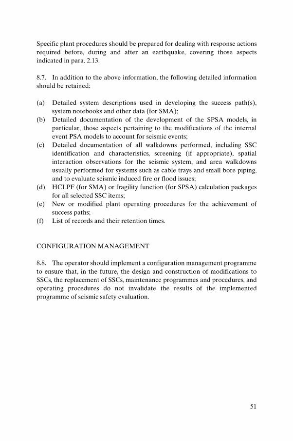
Specific plant procedures should be prepared for dealing with response actions required before, during and after an earthquake, covering those aspects indicated in para. 2.13.
8.7. In addition to the above information, the following detailed information should be retained:
(a) Detailed system descriptions used in developing the success path(s), system notebooks and other data (for SMA);
(b) Detailed documentation of the development of the SPSA models, in particular, those aspects pertaining to the modifications of the internal event PSA models to account for seismic events;
(c) Detailed documentation of all walkdowns performed, including SSC identification and characteristics, screening (if appropriate), spatial interaction observations for the seismic system, and area walkdowns usually performed for systems such as cable trays and small bore piping, and to evaluate seismic induced fire or flood issues;
(d) HCLPF (for SMA) or fragility function (for SPSA) calculation packages for all selected SSC items;
(e) New or modified plant operating procedures for the achievement of success paths;
(f) List of records and their retention times.
CONFIGURATION MANAGEMENT
8.8. The operator should implement a configuration management programme to ensure that, in the future, the design and construction of modifications to SSCs, the replacement of SSCs, maintenance programmes and procedures, and operating procedures do not invalidate the results of the implemented programme of seismic safety evaluation.
51

.
REFERENCES
[1] INTERNATIONAL ATOMIC ENERGY AGENCY, Safety of Nuclear Power Plants: Operation, IAEA Safety Standards Series No. NS-R-2, IAEA, Vienna (2000).
[2] INTERNATIONAL ATOMIC ENERGY AGENCY, Safety of Nuclear Power Plants: Design, IAEA Safety Standards Series No. NS-R-1, IAEA, Vienna (2000).
[3] INTERNATIONAL ATOMIC ENERGY AGENCY, Site Evaluation for Nuclear Installations, IAEA Safety Standards Series No. NS-R-3, IAEA, Vienna (2003).
[4] INTERNATIONAL ATOMIC ENERGY AGENCY, Evaluation of Seismic Hazards for Nuclear Power Plants, IAEA Safety Standards Series No. NS-G-3.3, IAEA, Vienna (2002) (revision in preparation).
[5] INTERNATIONAL ATOMIC ENERGY AGENCY, Seismic Design and Qualification for Nuclear Power Plants, IAEA Safety Standards Series No. NS-G-1.6, IAEA, Vienna (2003).
[6] INTERNATIONAL ATOMIC ENERGY AGENCY, Seismic Evaluation of Existing Nuclear Power Plants, Safety Reports Series No. 28, IAEA, Vienna (2003) (revision in preparation).
[7] INTERNATIONAL ATOMIC ENERGY AGENCY, Periodic Safety Review of Nuclear Power Plants, IAEA Safety Standards Series No. NS-G-2.10, IAEA, Vienna (2003).
[8] INTERNATIONAL ATOMIC ENERGY AGENCY, IAEA Safety Glossary: Terminology Used in Nuclear Safety and Radiation Protection, IAEA, Vienna (2007).
[9] INTERNATIONAL ATOMIC ENERGY AGENCY, Geotechnical Aspects of Site Evaluation and Foundations for Nuclear Power Plants, IAEA Safety Standards Series No. NS-G-3.6, IAEA, Vienna (2004).
[10] INTERNATIONAL ATOMIC ENERGY AGENCY, Flood Hazard for Nuclear Power Plants on Coastal and River Sites, IAEA Safety Standards Series No. NS-G-3.5, IAEA, Vienna (2003).
[11] INTERNATIONAL ATOMIC ENERGY AGENCY, External Events Excluding Earthquakes in the Design of Nuclear Power Plants, IAEA Safety Standards Series No. NS-G-1.5, IAEA, Vienna (2003).
[12] INTERNATIONAL ATOMIC ENERGY AGENCY, The Management System for Facilities and Activities, IAEA Safety Standards Series No. GS-R-3, IAEA, Vienna (2006).
[13] INTERNATIONAL ATOMIC ENERGY AGENCY, Application of the Management System for Facilities and Activities, IAEA Safety Standards Series No. GS-G-3.1, IAEA, Vienna (2006).
53
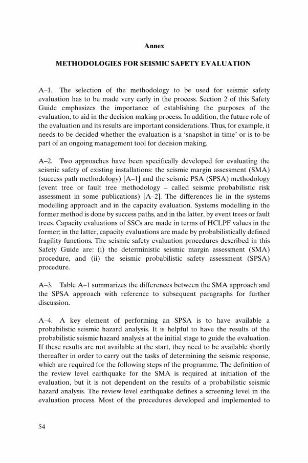
Annex
METHODOLOGIES FOR SEISMIC SAFETY EVALUATION
A–1. The selection of the methodology to be used for seismic safety evaluation has to be made very early in the process. Section 2 of this Safety Guide emphasizes the importance of establishing the purposes of the evaluation, to aid in the decision making process. In addition, the future role of the evaluation and its results are important considerations. Thus, for example, it needs to be decided whether the evaluation is a ‘snapshot in time’ or is to be part of an ongoing management tool for decision making.
A–2. Two approaches have been specifically developed for evaluating the seismic safety of existing installations: the seismic margin assessment (SMA) (success path methodology) [A–1] and the seismic PSA (SPSA) methodology (event tree or fault tree methodology – called seismic probabilistic risk assessment in some publications) [A–2]. The differences lie in the systems modelling approach and in the capacity evaluation. Systems modelling in the former method is done by success paths, and in the latter, by event trees or fault trees. Capacity evaluations of SSCs are made in terms of HCLPF values in the former; in the latter, capacity evaluations are made by probabilistically defined fragility functions. The seismic safety evaluation procedures described in this Safety Guide are: (i) the deterministic seismic margin assessment (SMA) procedure, and (ii) the seismic probabilistic safety assessment (SPSA) procedure.
A–3. Table A–1 summarizes the differences between the SMA approach and the SPSA approach with reference to subsequent paragraphs for further discussion.
A–4. A key element of performing an SPSA is to have available a probabilistic seismic hazard analysis. It is helpful to have the results of the probabilistic seismic hazard analysis at the initial stage to guide the evaluation. If these results are not available at the start, they need to be available shortly thereafter in order to carry out the tasks of determining the seismic response, which are required for the following steps of the programme. The definition of the review level earthquake for the SMA is required at initiation of the evaluation, but it is not dependent on the results of a probabilistic seismic hazard analysis. The review level earthquake defines a screening level in the evaluation process. Most of the procedures developed and implemented to
54
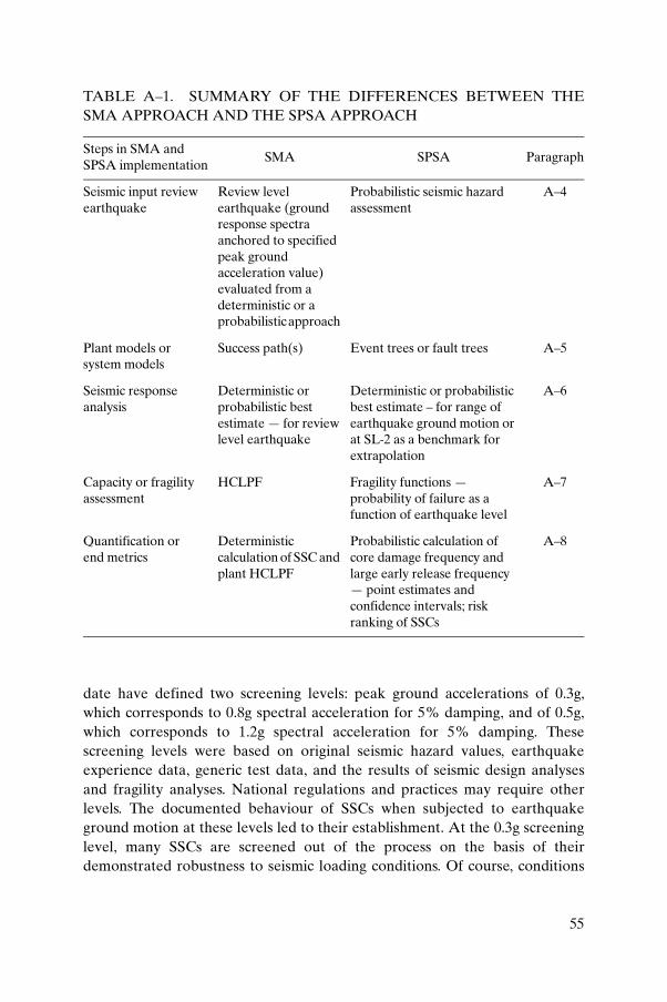
date have defined two screening levels: peak ground accelerations of 0.3g, which corresponds to 0.8g spectral acceleration for 5% damping, and of 0.5g, which corresponds to 1.2g spectral acceleration for 5% damping. These screening levels were based on original seismic hazard values, earthquake experience data, generic test data, and the results of seismic design analyses and fragility analyses. National regulations and practices may require other levels. The documented behaviour of SSCs when subjected to earthquake ground motion at these levels led to their establishment. At the 0.3g screening level, many SSCs are screened out of the process on the basis of their demonstrated robustness to seismic loading conditions. Of course, conditions
TABLE A–1. SUMMARY OF THE DIFFERENCES BETWEEN THE SMA APPROACH AND THE SPSA APPROACH
Steps in SMA and SPSA implementation
SMA SPSA Paragraph
Seismic input review earthquake
Review level earthquake (ground response spectra anchored to specified peak ground acceleration value) evaluated from a deterministic or a probabilistic approach
Probabilistic seismic hazard assessment
A–4
Plant models or system models
Success path(s) Event trees or fault trees A–5
Seismic response analysis
Deterministic or probabilistic best estimate — for review level earthquake
Deterministic or probabilistic best estimate – for range of earthquake ground motion or at SL-2 as a benchmark for extrapolation
A–6
Capacity or fragility assessment
HCLPF Fragility functions — probability of failure as a function of earthquake level
A–7
Quantification orend metrics
Deterministic calculation of SSC and plant HCLPF
Probabilistic calculation of core damage frequency and large early release frequency — point estimates and confidence intervals; risk ranking of SSCs
A–8
55
or caveats are imposed to allow the screening. For the 0.5g screening level, there is a significant increase in the scope of the SSCs to be individually evaluated.
A–5. The plant models or system models for the SMA and SPSA methodologies differ as follows:
(a) The SMA uses a success path approach. That is, given the end state to be achieved for the plant (e.g. safe shutdown), one or more paths of SSCs (called the selected SSCs) that can successfully bring the plant to this condition are defined. Items of the selected SSCs are evaluated by means of capacity screening, plant walkdown and HCLPF calculations.
(b) The SPSA system models are generally of the form of event trees and fault trees. Experience has demonstrated that cost effective SPSAs for complex facilities are based on available internal event PSAs. If new models are developed, there will be duplicated efforts and care has to be exercised to ensure that the models are consistent. The event trees and fault trees for the SPSA are based on these internal event system models, with modifications and additions to treat seismically induced failures that are not considered in the internal event case. Examples are passive failures and common cause effects.
A–6. The SMA and SPSA methodologies require seismic responses of (or seismic demands on) the selected SSCs:
(a) In the SMA, the best estimate (or median centred) seismic responses conditional on the review level earthquake are required.
(b) For the SPSA, probability distributions of seismic response (or seismic demand) conditional on the occurrence of an earthquake of significant size are required. The conditional seismic responses are usually anchored to the SL-2 earthquake level and extrapolated to the median fragility level, or they are directly calculated for the median fragility level.
A–7. For the SMA, capacities of selected SSCs are defined as HCLPF capacities. In probabilistic terms, the HCLPF capacity of an SSC is the earthquake motion level at which there is a high confidence (about 95%) of a low (5%) probability of failure. Frequency characteristics of this earthquake motion are described by the frequency characteristics of the review level earthquake. Although defined conceptually in a probabilistic sense, HCLPF values are almost always calculated by deterministic methods. Deterministic guidelines have been developed and demonstrated to yield the approximate
56
probabilistic definition. Examples are presented in Refs [A–1, A–2]. For the SMA, the procedures are such that seismic engineers without training in probabilistic methods can routinely calculate the HCLPFs. For the SPSA, fragility functions of the selected SSCs in the event trees (i.e. initiating event frequencies if at the level of a plant function) and in the fault trees are needed. Usually, these probabilistic estimates of fragility are made with significant contributions from experts in the field.
A–8. The philosophy of the development or calculation of the HCLPF by the conservative deterministic failure margin (CDFM) method1 is as follows:
(a) The loading function should be at a probability of non-exceedance of about 84%. This may be achieved in a number of ways. Most often this is defined in the ground motion definition step, that is, the review level earthquake is set at an 84% probability of non-exceedance or is interpreted as such. The review level earthquake may be specified as site independent, such as with median rock or soil response spectra, which may be interpreted to be equivalent to an 84% probability of non-exceedance of site specific ground motion. An alternative is to define the site specific ground motion, including its variability, and explicitly to analyse the structures of interest, calculating 84% probability of non-exceedance for responses of the structure (forces or moments in structural elements, in-structure response spectra and other response quantities of interest) for input to the evaluation of selected SSCs.
(b) The strength or capacity of ductile items should be targeted at a 98% probability of non-exceedance. The strength or capacity of brittle items should be targeted at a 99% probability of non-exceedance.
A–9. Quantification of the plant HCLPF for the SMA is achieved relatively simply by evaluating the success paths given the HCLPF values of selected SSCs. The end result of the SMA is a plant HCLPF value, that is, the ground motion descriptor at which one can state that there is high confidence that the plant can be safely shut down given the conditions specified initially. Weak links are identified, that is, selected SSCs with low HCLPF values or operations that lead to low plant HCLPF values. Decisions about upgrading can be made on the basis of these HCLPF values. For risk informed decision making or other risk based applications, seismic hazard information needs to be related to the plant HCLPF values. This is done by relating the plant HCLPF values to a
1 In the CDPM method, the seismic margin of an SSC is calculated by using a set of deterministic rules that are more realistic than design procedures.
57
generic curve for the plant fragility function. The calculation of the probability of plant failure is a result of the convolution of the probabilistic seismic hazard with the plant fragility curve.
A–10. For the SPSA, the calculation of core damage frequency and large early release frequency is a result of the convolution of the seismic hazard with the fragility functions over the event trees and fault trees. Alternatively, the same quantities can be calculated for each ground motion interval. The end results are point estimates or confidence intervals of the end metrics of interest.
A–11. Many common elements exist for the SMA and SPSA approaches:
(a) An assessment of the seismic hazard at the specific site of interest. For the SMA, a review level earthquake is defined as a deterministic definition of the seismic input against which the capacity of the facility is assessed. For the SPSA, a probabilistic seismic hazard is defined, most often from a probabilistic seismic hazard assessment [A–2].
(b) Identification of the SSCs for which a capacity evaluation is performed. For the SMA, these components are defined from the safe shutdown path(s) and are called the safe shutdown equipment list or selected SSCs. For the SPSA, an initial list of SSCs greater in number than those in the SMA safe shutdown equipment list is identified. Through screening and other techniques, the final list of SSCs for detailed capacity evaluation is significantly reduced.
(c) In-plant evaluations or walkdowns are essential elements of the SMA and the SPSA.
(d) Quantification of the installation capacity is made in terms of an HCLPF value for the plant when an SMA is performed. For the SPSA, typical outputs of the assessment are core damage frequency and large early release frequency, or surrogates of these. The installation HCLPF is a by-product of the SPSA. In both cases, an importance ranking of SSCs is obtained.
(e) Sensitivity studies are performed to assess the impact of plant modifications (physical and operational) on the end results.
A–12. Earthquake experience data and compilations of dynamic test results of component qualification and, if available, component fragility data are very useful in the execution of the SMA or SPSA. The estimate of the seismic capacity of systems and components is often accomplished by the use of experience gained from seismic events generating very strong motion. Data from strong motion earthquakes have generally been collected to provide the
58
information required for directly verifying the seismic adequacy of individual items in existing plants. Such verification requires:
(a) Demonstration that the seismic input to the database facility (i.e. the facility with the documented SSC performance in the database) appropriately exceeds the seismic input of the facility being seismically evaluated;
(b) Demonstration that the SSC being evaluated and the database item are similar in physical characteristics, including supports and/or anchorages.
Alternatively, the support or anchorage capacities can be evaluated by means of additional analysis. In the case of active items, it is necessary to show that the item that was subjected to the strong motion earthquake performed similar functions during or following that earthquake, including possible aftershock effects, as would be required for the safety related item being evaluated.
A–13. Some SSCs are specialized and cannot be treated using earthquake experience data and generic test data. An example of such SSCs is the nuclear steam supply system and supporting structure. For these SSCs, when they are designated selected SSCs, seismic safety evaluation for the SMA or SPSA is based on seismic analysis to determine stress and strain levels, which may then be converted to deterministic HCLPF values or fragility functions. Seismic responses are calculated as median centred, as discussed in para. A–6. The results of system and component specific qualification or fragility tests, if available, are valuable in determining HCLPF values or fragility functions. An example of selected SSC test results valuable to the assessment is the testing of control rod drive insertion and the control rod drive system. Often, seismic analysis is the basis for evaluation of structures, parts of systems and mechanical components where the failure mode is stress or strain related. For electrical or instrumentation and control equipment, qualification or fragility tests are the basis for their evaluation.
A–14. The evolution of procedures especially related to earthquake experience data was initiated in response to a request by the United States Nuclear Regulatory Commission. This led to a judgemental procedure based on earthquake experience and tests (i.e. the generic implementation procedure described in Ref. [A–3]) that uses seismic empirical methods to verify the seismic adequacy of the specified safety related equipment in operating nuclear power plants. This procedure is based primarily on the performance of installed mechanical and electrical equipment that has been subjected to actual strong motion earthquakes, as well as on the behaviour of equipment components
59
during simulated seismic tests. It is pointed out, however, that unspecified uncertainties exist in some of these qualification data. Caution should be exercised, especially in using data originating from older nuclear (and non-nuclear) plants.
A–15. Before the data are used for a specific evaluation, their suitability for application should be verified. The procedure was adapted for application to other types of nuclear power plant outside the United States of America, particularly to water cooled, water moderated (WWER) plants in eastern Europe. This type of adaptation requires that the adequacy of the available database be carefully assessed and, possibly, that a new database be set up, because components used in one State may be of a design significantly different from those used in another, and therefore may not be represented in the available database.
REFERENCES TO THE ANNEX
[A–1] ELECTRIC POWER RESEARCH INSTITUTE, A Methodology for Assessment of Nuclear Power Plant Seismic Margin, Rep. EPRI NP-6041-SL, Rev. 1, EPRI, Palo Alto, CA, (1991).
[A–2] AMERICAN NUCLEAR SOCIETY, External Events PRA Methodology, Rep. ANSI/ANS-58.21-2007, ANS, La Grange Park, IL (2007).
[A–3] SEISMIC QUALIFICATION UTILITIES GROUP, Generic Implementation Procedure for Seismic Verification of Nuclear Power Plant Equipment, Rev. 2, Office of Standards Development, Washington, DC (1992).
60

CONTRIBUTORS TO DRAFTING AND REVIEW
Abe, H. Japan Nuclear Energy Safety Organization, Japan
Chigama, A. International Atomic Energy Agency
Godoy, A. International Atomic Energy Agency
Gürpinar, A. International Atomic Energy Agency
Ibrahim, A. Canadian Nuclear Safety Commission, Canada
Jimenez Juan, A. Consejo de Seguridad Nuclear, Spain
Johnson, J. James J. Johnson & Associates,United States of America
Kostarev, V. CKTI-Vibroseism Co. Ltd, Russian Federation
Kostov, M. Risk Engineering Ltd, Bulgaria
Krutzik, N. NJK Consulting, Germany
Labbé, P. Électricité de France, France
Nagasawa, K. Tokyo Electric Power Company, Japan
Rambach, J.-M. Institut de radioprotection et de sûreté nucléaire, France
Ricciuti, R. Atomic Energy of Canada Limited, Canada
Schotten, T. Consultant, Switzerland
Shibata, H. Association for the Development of Earthquake Prediction, Japan
Shokr, A. International Atomic Energy Agency
Sollogoub, P. Commissariat à l’énergie atomique, France
Stevenson, J.D. Consultant, United States of America
61

.
BODIES FOR THE ENDORSEMENTOF IAEA SAFETY STANDARDS
An asterisk denotes a corresponding member. Corresponding members receive drafts for comment and other documentation but they do not generally participate in meetings. Two asterisks denote an alternate.
Commission on Safety Standards
Argentina: González, A.J.; Australia: Loy, J.; Belgium: Samain, J.-P.; Brazil:Vinhas, L.A.; Canada: Jammal, R.; China: Liu Hua; Egypt: Barakat, M.; Finland: Laaksonen, J.; France: Lacoste, A.-C. (Chairperson); Germany: Majer, D.; India: Sharma, S.K.; Israel: Levanon, I.; Japan: Fukushima, A.; Korea, Republic of: Choul-Ho Yun; Lithuania: Maksimovas, G.; Pakistan: Rahman, M.S.; Russian Federation: Adamchik, S.; South Africa: Magugumela, M.T.; Spain: Barceló Vernet, J.; Sweden: Larsson, C.M.; Ukraine: Mykolaichuk, O.; United Kingdom: Weightman, M.; United States of America: Virgilio, M.; Vietnam: Le-chi Dung; IAEA: Delattre, D. (Coordinator); Advisory Group on Nuclear Security: Hashmi, J.A.; European Commission: Faross, P.; International Nuclear Safety Group: Meserve, R.; International Commission on Radiological Protection: Holm, L.-E.; OECD Nuclear Energy Agency: Yoshimura, U.; Safety Standards Committee Chairpersons: Brach, E.W. (TRANSSC); Magnusson, S. (RASSC); Pather, T. (WASSC); Vaughan, G.J. (NUSSC).
Nuclear Safety Standards Committee
Algeria: Merrouche, D.; Argentina: Waldman, R.; Australia: Le Cann, G.; Austria: Sholly, S.; Belgium: De Boeck, B.; Brazil: Gromann, A.; *Bulgaria: Gledachev, Y.; Canada: Rzentkowski, G.; China: Jingxi Li; Croatia: Valčić, I.; *Cyprus: Demetriades, P.; Czech Republic: Šváb, M.; Egypt: Ibrahim, M.; Finland: Järvinen, M.-L.; France: Feron, F.; Germany: Wassilew, C.; Ghana: Emi-Reynolds, G.; *Greece: Camarinopoulos, L.; Hungary: Adorján, F.; India: Vaze, K.; Indonesia: Antariksawan, A.; Iran, Islamic Republic of: Asgharizadeh, F.; Israel: Hirshfeld, H.; Italy: Bava, G.; Japan: Kanda, T.; Korea, Republic of: Hyun-Koon Kim; Libyan Arab Jamahiriya: Abuzid, O.; Lithuania: Demčenko, M.; Malaysia: Azlina Mohammed Jais; Mexico: Carrera, A.; Morocco: Soufi, I.; Netherlands: van der Wiel, L.; Pakistan: Habib, M.A.; Poland: Jurkowski, M.; Romania: Biro, L.; Russian Federation: Baranaev, Y.; Slovakia: Uhrik, P.; Slovenia: Vojnovič, D.; South Africa: Leotwane, W.; Spain: Zarzuela, J.; Sweden: Hallman, A.; Switzerland: Flury, P.; Tunisia: Baccouche, S.;
63
Turkey: Bezdegumeli, U.; Ukraine: Shumkova, N.; United Kingdom: Vaughan, G.J. (Chairperson); United States of America: Mayfield, M.; Uruguay: Nader, A.; European Commission: Vigne, S.; FORATOM: Fourest, B.; IAEA: Feige, G. (Coordinator); International Electrotechnical Commission: Bouard, J.-P.; International Organization for Standardization: Sevestre, B.; OECD Nuclear Energy Agency: Reig, J.; *World Nuclear Association: Borysova, I.
Radiation Safety Standards Committee
*Algeria: Chelbani, S.; Argentina: Massera, G.; Australia: Melbourne, A.; *Austria: Karg, V.; Belgium: van Bladel, L.; Brazil: Rodriguez Rochedo, E.R.; *Bulgaria: Katzarska, L.; Canada: Clement, C.; China: Huating Yang; Croatia:Kralik, I.; *Cuba: Betancourt Hernandez, L.; *Cyprus: Demetriades, P.; Czech Republic: Petrova, K.; Denmark: Øhlenschlæger, M.; Egypt: Hassib, G.M.; Estonia: Lust, M.; Finland: Markkanen, M.; France: Godet, J.-L.; Germany: Helming, M.; Ghana: Amoako, J.; *Greece: Kamenopoulou, V.; Hungary: Koblinger, L.; Iceland: Magnusson, S. (Chairperson); India: Sharma, D.N.; Indonesia: Widodo, S.; Iran, Islamic Republic of: Kardan, M.R.; Ireland: Colgan, T.; Israel: Koch, J.; Italy: Bologna, L.; Japan: Kiryu, Y.; Korea, Republic of: Byung-Soo Lee; *Latvia: Salmins, A.; Libyan Arab Jamahiriya: Busitta, M.; Lithuania: Mastauskas, A.; Malaysia: Hamrah, M.A.; Mexico: Delgado Guardado, J.; Morocco: Tazi, S.; Netherlands: Zuur, C.; Norway: Saxebol, G.; Pakistan: Ali, M.; Paraguay: Romero de Gonzalez, V.; Philippines: Valdezco, E.; Poland: Merta, A.; Portugal: Dias de Oliveira, A.M.; Romania: Rodna, A.; Russian Federation: Savkin, M.; Slovakia: Jurina, V.; Slovenia: Sutej, T.; South Africa: Olivier, J.H.I.; Spain: Amor Calvo, I.; Sweden: Almen, A.; Switzerland: Piller, G.; *Thailand: Suntarapai, P.; Tunisia: Chékir, Z.; Turkey: Okyar, H.B.; Ukraine: Pavlenko, T.; United Kingdom: Robinson, I.; United States of America: Lewis, R.; *Uruguay: Nader, A.; European Commission: Janssens, A.; Food and Agriculture Organization of the United Nations: Byron, D.; IAEA: Boal, T. (Coordinator); International Commission on Radiological Protection: Valentin, J.; International Electrotechnical Commission: Thompson, I.; International Labour Office: Niu, S.; International Organization for Standardization: Rannou, A.; International Source Suppliers and Producers Association: Fasten, W.; OECD Nuclear Energy Agency: Lazo, T.E.; Pan American Health Organization: Jiménez, P.; United Nations Scientific Committee on the Effects of Atomic Radiation: Crick, M.; World Health Organization: Carr, Z.; World Nuclear Association: Saint-Pierre, S.
64
Transport Safety Standards Committee
Argentina: López Vietri, J.; **Capadona, N.M.; Australia: Sarkar, S.; Austria:Kirchnawy, F.; Belgium: Cottens, E.; Brazil: Xavier, A.M.; Bulgaria: Bakalova, A.; Canada: Régimbald, A.; China: Xiaoqing Li; Croatia:Belamarić, N.; *Cuba: Quevedo Garcia, J.R.; *Cyprus: Demetriades, P.; Czech Republic: Ducháček, V.; Denmark: Breddam, K.; Egypt: El-Shinawy, R.M.K.; Finland: Lahkola, A.; France: Landier, D.; Germany: Rein, H.; *Nitsche, F.; **Alter, U.; Ghana: Emi-Reynolds, G.; *Greece: Vogiatzi, S.; Hungary: Sáfár, J.; India: Agarwal, S.P.; Indonesia: Wisnubroto, D.; Iran, Islamic Republic of:Eshraghi, A.; *Emamjomeh, A.; Ireland: Duffy, J.; Israel: Koch, J.; Italy: Trivelloni, S.; **Orsini, A.; Japan: Hanaki, I.; Korea, Republic of: Dae-Hyung Cho; Libyan Arab Jamahiriya: Kekli, A.T.; Lithuania: Statkus, V.; Malaysia:Sobari, M.P.M.; **Husain, Z.A.; Mexico: Bautista Arteaga, D.M.; **Delgado Guardado, J.L.; *Morocco: Allach, A.; Netherlands: Ter Morshuizen, M.; *New Zealand: Ardouin, C.; Norway: Hornkjøl, S.; Pakistan: Rashid, M.; *Paraguay:More Torres, L.E.; Poland: Dziubiak, T.; Portugal: Buxo da Trindade, R.; Russian Federation: Buchelnikov, A.E.; South Africa: Hinrichsen, P.; Spain: Zamora Martin, F.; Sweden: Häggblom, E.; **Svahn, B.; Switzerland: Krietsch, T.; Thailand: Jerachanchai, S.; Turkey: Ertürk, K.; Ukraine: Lopatin, S.; United Kingdom: Sallit, G.; United States of America: Boyle, R.W.; Brach, E.W. (Chairperson); Uruguay: Nader, A.; *Cabral, W.; European Commission: Binet, J.; IAEA: Stewart, J.T. (Coordinator); International Air Transport Association:Brennan, D.; International Civil Aviation Organization: Rooney, K.; International Federation of Air Line Pilots’ Associations: Tisdall, A.; **Gessl, M.; International Maritime Organization: Rahim, I.; International Organization for Standardization: Malesys, P.; International Source Supplies and Producers Association: Miller, J.J.; **Roughan, K.; United Nations Economic Commission for Europe: Kervella, O.; Universal Postal Union: Bowers, D.G.; World Nuclear Association: Gorlin, S.; World Nuclear Transport Institute: Green, L.
Waste Safety Standards Committee
Algeria: Abdenacer, G.; Argentina: Biaggio, A.; Australia: Williams, G.; *Austria: Fischer, H.; Belgium: Blommaert, W.; Brazil: Tostes, M.; *Bulgaria: Simeonov, G.; Canada: Howard, D.; China: Zhimin Qu; Croatia: Trifunovic, D.; Cuba: Fernandez, A.; Cyprus: Demetriades, P.; Czech Republic: Lietava, P.; Denmark: Nielsen, C.; Egypt: Mohamed, Y.; Estonia: Lust, M.; Finland: Hutri, K.; France: Rieu, J.; Germany: Götz, C.; Ghana: Faanu, A.; Greece: Tzika, F.; Hungary: Czoch, I.; India: Rana, D.; Indonesia: Wisnubroto, D.; Iran, Islamic
65
Republic of: Assadi, M.; *Zarghami, R.; Iraq: Abbas, H.; Israel: Dody, A.; Italy: Dionisi, M.; Japan: Matsuo, H.; Korea, Republic of: Won-Jae Park; *Latvia: Salmins, A.; Libyan Arab Jamahiriya: Elfawares, A.; Lithuania: Paulikas, V.; Malaysia: Sudin, M.; Mexico: Aguirre Gómez, J.; *Morocco: Barkouch, R.;Netherlands: van der Shaaf, M.; Pakistan: Mannan, A.; *Paraguay: Idoyaga Navarro, M.; Poland: Wlodarski, J.; Portugal: Flausino de Paiva, M.; Slovakia: Homola, J.; Slovenia: Mele, I.; South Africa: Pather, T. (Chairperson); Spain: Sanz Aludan, M.; Sweden: Frise, L.; Switzerland: Wanner, H.; *Thailand: Supaokit, P.; Tunisia: Bousselmi, M.; Turkey: Özdemir, T.; Ukraine: Makarovska, O.; United Kingdom: Chandler, S.; United States of America: Camper, L.; *Uruguay:Nader, A.; European Commission: Necheva, C.; European Nuclear Installations Safety Standards: Lorenz, B.; *European Nuclear Installations Safety Standards:Zaiss, W.; IAEA: Siraky, G. (Coordinator); International Organization for Standardization: Hutson, G.; International Source Suppliers and Producers Association: Fasten, W.; OECD Nuclear Energy Agency: Riotte, H.; World Nuclear Association: Saint-Pierre, S.
66
IAEA SAFETY RELATED PUBLICATIONS
IAEA SAFETY STANDARDS
Under the terms of Article III of its Statute, the IAEA is authorized to establish or adopt standards of safety for protection of health and minimization of danger to life and property, and to provide for the application of these standards.
The publications by means of which the IAEA establishes standards are issued in the IAEA Safety Standards Series. This series covers nuclear safety, radiation safety, transport safety and waste safety. The publication categories in the series are Safety Fundamentals, Safety Requirements and Safety Guides.
Information on the IAEA’s safety standards programme is available at the IAEA Internet site
http://www-ns.iaea.org/standards/
The site provides the texts in English of published and draft safety standards. The texts of safety standards issued in Arabic, Chinese, French, Russian and Spanish, the IAEA Safety Glossary and a status report for safety standards under development are also available. For further information, please contact the IAEA at P.O. Box 100, 1400 Vienna, Austria.
All users of IAEA safety standards are invited to inform the IAEA of experience in their use (e.g. as a basis for national regulations, for safety reviews and for training courses) for the purpose of ensuring that they continue to meet users’ needs. Information may be provided via the IAEA Internet site or by post, as above, or by email to [email protected].
OTHER SAFETY RELATED PUBLICATIONS
The IAEA provides for the application of the standards and, under the terms of Articles III and VIII.C of its Statute, makes available and fosters the exchange of information relating to peaceful nuclear activities and serves as an intermediary among its Member States for this purpose.
Reports on safety and protection in nuclear activities are issued as Safety Reports, which provide practical examples and detailed methods that can be used in support of the safety standards.
Other safety related IAEA publications are issued as Radiological Assessment Reports, the International Nuclear Safety Group’s INSAG Reports, Technical Reportsand TECDOCs. The IAEA also issues reports on radiological accidents, training manuals and practical manuals, and other special safety related publications. Security related publications are issued in the IAEA Nuclear Security Series.
RELATED PUBLICATIONS
www.iaea.org/books
FUNDAMENTAL SAFETY PRINCIPLESIAEA Safety Standards Series No. SF-1STI/PUB/1273 (37 pp.; 2006) ISBN 92–0–110706–4 Price: €25.00
SAFETY OF NUCLEAR POWER PLANTS: OPERATIONIAEA Safety Standards Series No. NS-R-2STI/PUB/1096 (40 pp.; 2000) ISBN 92–0–100700–0 Price: €11.50
CONDUCT OF OPERATIONS AT NUCLEAR POWER PLANTSIAEA Safety Standards Series No. NS-G-2.14STI/PUB/1339 (66 pp.; 2008) ISBN 978–92–0–105408–1 Price: €19.00
AGEING MANAGEMENT FOR NUCLEAR POWER PLANTSIAEA Safety Standards Series No. NS-G-2.12STI/PUB/1373 (65 pp.; 2009) ISBN 978–92–0–112408–1 Price: €20.00
A SYSTEM FOR THE FEEDBACK OF EXPERIENCE FROM EVENTS IN NUCLEAR INSTALLATIONSIAEA Safety Standards Series No. NS-G-2.11STI/PUB/1243 (79 pp.; 2006) ISBN 92–0–101406–6 Price: €23.00
PERIODIC SAFETY REVIEW OF NUCLEAR POWER PLANTSIAEA Safety Standards Series No. NS-G-2.10STI/PUB/1157 (62 pp.; 2003) ISBN 92–0–108503–6 Price: €15.50
COMMISSIONING FOR NUCLEAR POWER PLANTSIAEA Safety Standards Series No. NS-G-2.9STI/PUB/1152 (77 pp.; 2003) ISBN 92–0–104103–9 Price: €20.00
RECRUITMENT, QUALIFICATION AND TRAINING OF PERSONNEL FOR NUCLEAR POWER PLANTSIAEA Safety Standards Series No. NS-G-2.8STI/PUB/1140 (57 pp.; 2002) ISBN 92–0–117902–2 Price: €15.50
RADIATION PROTECTION AND RADIOACTIVE WASTE MANAGEMENT IN THE OPERATION OF NUCLEAR POWER PLANTSIAEA Safety Standards Series No. NS-G-2.7STI/PUB/1138 (71 pp.; 2002) ISBN 92–0–119202–9 Price: €18.00
P1379_covI-IV.indd 2 2009-05-22 14:24:19

INTERNATIONAL ATOMIC ENERGY AGENCYVIENNA
ISBN 978–92 –0–100409–3ISSN 1020–525X
“The IAEA’s standards have become a key element of the global safety regime for the beneficial uses of nuclear and radiation related technologies.
“IAEA safety standards are being applied in nuclear power generation as well as in medicine, industry, agriculture, research and education to ensure the proper protection of people and the environment.”
Mohamed ElBaradeiIAEA Director General
Safety through international standardsIAEA Safety Standards
Evaluation of Seismic Safety for Existing Nuclear Installations
for protecting people and the environment
No. NS-G-2.13Safety Guide
84 pages, 5.3mm
P1379_covI-IV.indd 1 2009-05-22 14:24:19