Embed Size (px)
Citation preview
8/7/2019 IBJSC.com | I-WEB.com.vn - 953467670
http://slidepdf.com/reader/full/ibjsccom-i-webcomvn-953467670 1/92
AV SURROUND RECEIVER
AVR-2311CIOwner’s ManualManuel de l’Utilisateur
Manual del usuario
Simpleversion
Version simpliée
Versión sencilla
v 3
Basic
version
Version basique
Versión básica
v 12
Advancedversion
Version avancée
Versión avanzada
v 31
Information “Part names and functions”
(vpage 70)
v 69Informations
“Nomenclature et fonctions“
(vpage 70)
Información
“Nombres y funciones de las
piezas“ (vpágina 70)
8/7/2019 IBJSC.com | I-WEB.com.vn - 953467670
http://slidepdf.com/reader/full/ibjsccom-i-webcomvn-953467670 2/92
8/7/2019 IBJSC.com | I-WEB.com.vn - 953467670
http://slidepdf.com/reader/full/ibjsccom-i-webcomvn-953467670 3/92
I
ENGLISHFRANCAISESPAÑOL
nSAFETY PRECAUTIONS
CAUTIONRISK OF ELECTRIC SHOCK
DO NOT OPEN
CAUTION:TO REDUCE THE RISK OF ELECTRIC SHOCK, DO NOT REMOVECOVER (OR BACK). NO USER-SERVICEABLE PARTS INSIDE.REFER SERVICING TO QUALIFIED SERVICE PERSONNEL.
The lightning ash with arrowhead symbol, within an equilateraltriangle, is intended to alert the user to the presence o
uninsulated “dangerous voltage” within the product’s enclosure
that may be o sufcient magnitude to constitute a risk o
electric shock to persons.
The exclamation point within an equilateral triangle is intended
to alert the user to the presence o important operating
and maintenance (servicing) instructions in the literature
accompanying the appliance.
WARNING:TO REDUCE THE RISK OF FIRE OR ELECTRIC SHOCK, DO NOTEXPOSE THIS APPLIANCE TO RAIN OR MOISTURE.
CAUTION:To completely disconnect this product rom the mains, disconnect the plug
rom the wall socket outlet.
The mains plug is used to completely interrupt the power supply to the unit
and must be within easy access by the user.
PRECAUTION:Pour déconnecter complètement ce produit du courant secteur, débranchez
la prise de la prise murale.
La prise secteur est utilisée pour couper complètement l’alimentation de
l’appareil et l’utilisateur doit pouvoir y accéder acilement.
PRECAUCIÓN:Para desconectar completamente este producto de la alim entación eléctrica,
desconecte el enchue del enchue de la pared.
El enchue de la alimentación eléctrica se utiliza para interrumpir por completo
el suministro de alimentación eléctrica a la unidad y debe de encontrarse en
un lugar al que el usuario tenga ácil acceso.
IMPORTANT SAFETYINSTRUCTIONS
1. Read these instructions.
2. Keep these instructions.
3. Heed all warnings.
4. Follow all instructions.
5. Do not use this apparatus near water.
6. Clean only with dry cloth.
7. Do not block any ventilation openings.
Install in accordance with the manuacturer’s instructions.
8. Do not install near any heat sources such as radiators, heat registers,
stoves, or other apparatus (including amplifers) that produce heat.9. Do not deeat the saety purpose o the polarized or grounding-type plug. A
polarized plug has two blades with one wider than the other. A grounding
type plug has two blades and a third gr ounding prong. The wide blade or the
third prong are provided or your saety. I the provided plug does not ft into
your outlet, consult an electrician or replacement o the obsolete outlet.
10. Protect the power cord rom being walked on or pinched particularly at
plugs, convenience receptacles, and the point where they exit rom the
apparatus.
11. Only use attachments/accessories specifed by the manuacturer.
12. Use only with the cart, stand, tripod, bracket, or table
specifed by the manuacturer, or sold w ith the apparatus.
When a cart is used, use caution when moving the cart/
apparatus combination to avoid injury rom tip-over.
13. Unplug this apparatus during lightning storms or when
unused or long periods o time.
14. Reer all servicing t o qualifed service personnel.Servicing is required when the apparatus has been damaged in any way,
such as power-supply cord or plug is damaged, liquid has been spilled or
objects have allen into the apparatus, the apparatus has been exposed to
rain or moisture, does not operate normally, or has been dropped.
15. Batteries shall not be exposed to excessive heat such as sunshine, fre or
the like.
CAUTION:HOT SURFACE. DO NOT TOUCH.The top surace over the internal heat sink may become hot
when operating this product continuously.
Do not touch hot areas, especially around the “Hot surace
mark” and the top panel.
PRECAUTION:SURFACE CHAUDE. NE PAS TOUCHER.La surace supérieure du dissipateur de chaleur peut devenir
chaude si vous utilisez ce produit en continu.
Do not touch hot areas, especially around the “Hot surace
mark” and the top panel.
PRECAUCIÓN:SUPERFICIE CALIENTE. NO TOCAR.La superfcie superior sobre el disipador de calor interno
podría llegar a calentarse al operar este producto de orma
continua.
Do not touch hot areas, especially around the “Hot surace
mark” and the top panel.
FCC INFORMATION (For US customers)
1. PRODUCTThis product complies with Part 15 o the FCC Rules. Operation is subject
to the ollowing two conditions: (1) this product may not cause harmul
intererence, and (2) this product must accept any intererence received,
including intererence that may cause undesired operation.
2. IMPORTANT NOTICE: DO NOT MODIFY THIS PRODUCTThis product, when installed as indicated in the instructions contained
in this manual, meets FCC requirements. Modifcation not expressly
approved by DENON may void your authority, granted by the FCC, to use
the product.
3. NOTEThis product has been tested and ound to comply with the limits or
a Class B digital device, pursuant to Part 15 o the FCC Rules. These
limits are designed to provide reasonable protection against harmul
intererence in a residential installation.
This product generates, uses and can radiate radio requency energy and,
i not installed and used in accordance with the instructions, may cause
harmul intererence to radio communications. However, there is no
guarantee that intererence will not occur in a particular installation. I this
product does cause harmul intererence to radio or television reception,
which can be determined by turning the product OFF and ON, the user
is encouraged to try to correct the intererence by one or more o the
ollowing measures:
• Reorient or relocate the receiving antenna.
• Increase the separation between the equipment and receiver.
• Connect the product into an outlet on a circuit dierent rom that to
which the receiver is connected.
• Consult the local retailer authorized to distribute this type o product or
an experienced radio/TV technician or help.
For Canadian customers:This Class B digital apparatus complies with Canadian ICES-003.
Cet appareil numérique de la classe B est conorme à la norme NMB-003 du
Canada.
Hot
surace
mark
8/7/2019 IBJSC.com | I-WEB.com.vn - 953467670
http://slidepdf.com/reader/full/ibjsccom-i-webcomvn-953467670 4/92
II
ESPAÑOLENGLISH FRANCAIS
nNOTES ON USE / OBSERVATIONS RELATIVES A L’UTILISATION / NOTAS SOBRE EL USO
WARNINGS AVERTISSEMENTS ADVERTENCIAS• Avoid high temperatures.
Allow or sufcient heat dispersion when
installed in a rack.
• Handle the power cord careully.
Hold the plug when unplugging the cord.
• Keep the unit ree rom moisture, water, and
dust.
• Unplug the power cord when not using the unit
or long periods o time.
• Do not obstruct the ventilation holes.
• Do not let oreign objects into the unit.
• Do not let insecticides, benzene, and thi nner
come in contact with the unit.
• Never disassemble or modiy the unit in any way.
• Ventilation should not be impeded by covering
the ventilation openings with items, such as
newspapers, tablecloths or curtains.
• Naked ame sources such as lighted candles
should not be placed on the unit.
• Observe and ollow local regulations regarding
battery disposal.
• Do not expose the unit to dripping or splashing
uids.
• Do not place objects flled with liquids, such as
vases, on the unit.
• Do not handle the mains cord with wet hands.• When the switch is in the OFF position, t he
equipment is not completely switched o rom
MAINS.
• The equipment shall be installed near the
power supply so that the power supply is easily
accessible.
• Eviter des températures élevées.
Tenir compte d’une dispersion de chaleur
sufsante lors de l’installation sur une étagère.
• Manipuler le cordon d’alimentation avec
précaution.
Tenir la prise lors du débranchement du cordon.
• Protéger l’appareil contre l’humidité, l’eau et la
poussière.
• Débrancher le cordon d’alimentation lorsque
l’appareil n’est pas utilisé pendant de longues
périodes.
• Ne pas obstruer les trous d’aération.
• Ne pas laisser des objets étrangers dans
l’appareil.
• Ne pas mettre en contact des insecticides, du
benzène et un diluant avec l’appareil.
• Ne jamais démonter ou modifer l’appareil d’une
manière ou d’une autre.
• Ne pas recouvrir les orifces de ventilation avec
des objets tels que des journaux, nappes ou
rideaux. Cela entraverait la ventilation.
• Ne jamais placer de amme nue sur l’appareil,
notamment des bougies allumées.
• Veillez à respecter les lois en vigueur lorsque
vous jetez les piles usagées.
• L’appareil ne doit pas être exposé à l’eau ou àl’humidité.
• Ne pas poser d’objet contenant du liquide, par
exemple un vase, sur l’appareil.
• Ne pas manipuler le cordon d’alimentation avec
les mains mouillées.
• Lorsque l’interrupteur est sur la position OFF,
l’appareil n’est pas complètement déconnecté du
SECTEUR (MAINS).
• L’appareil sera installé près de la source
d’alimentation, de sorte que cette dernière soit
acilement accessible.
• Evite altas temperaturas.
Permite la sufciente dispersión del calor cuando
está instalado en la consola.
• Maneje el cordón de energía con cuidado.
Sostenga el enchue cuando desconecte el
cordón de energía.
• Mantenga el equipo libre de humedad, agua y
polvo.
• Desconecte el cordón de energía cuando no
utilice el equipo por mucho tiempo.
• No obstruya los orifcios de ventilación.
• No deje objetos extraños dentro del equipo.
• No permita el contacto de insecticidas, gasolina
y diluyentes con el equipo.
• Nunca desarme o modifque el equipo de
ninguna manera.
• La ventilación no debe quedar obstruida por
haberse cubierto las aperturas con objetos como
periódicos, manteles o cortinas.
• No deberán colocarse sobre el aparato uentes
inamables sin protección, como velas
encendidas.
• A la hora de deshacerse de las pilas, respete la
normativa para el cuidado del medio ambiente.
• No exponer el aparato al goteo o salpicaduras
cuando se utilice.• No colocar sobre el aparato objetos llenos de
líquido, como jarros.
• No maneje el cable de alimentación con las
manos mojadas.
• Cuando el interruptor está en la posición OFF, el
equipo no está completamente desconectado de
la alimentación MAINS.
• El equipo se instalar á cerca de la uente de
alimentación de manera que resulte ácil acceder
a ella.
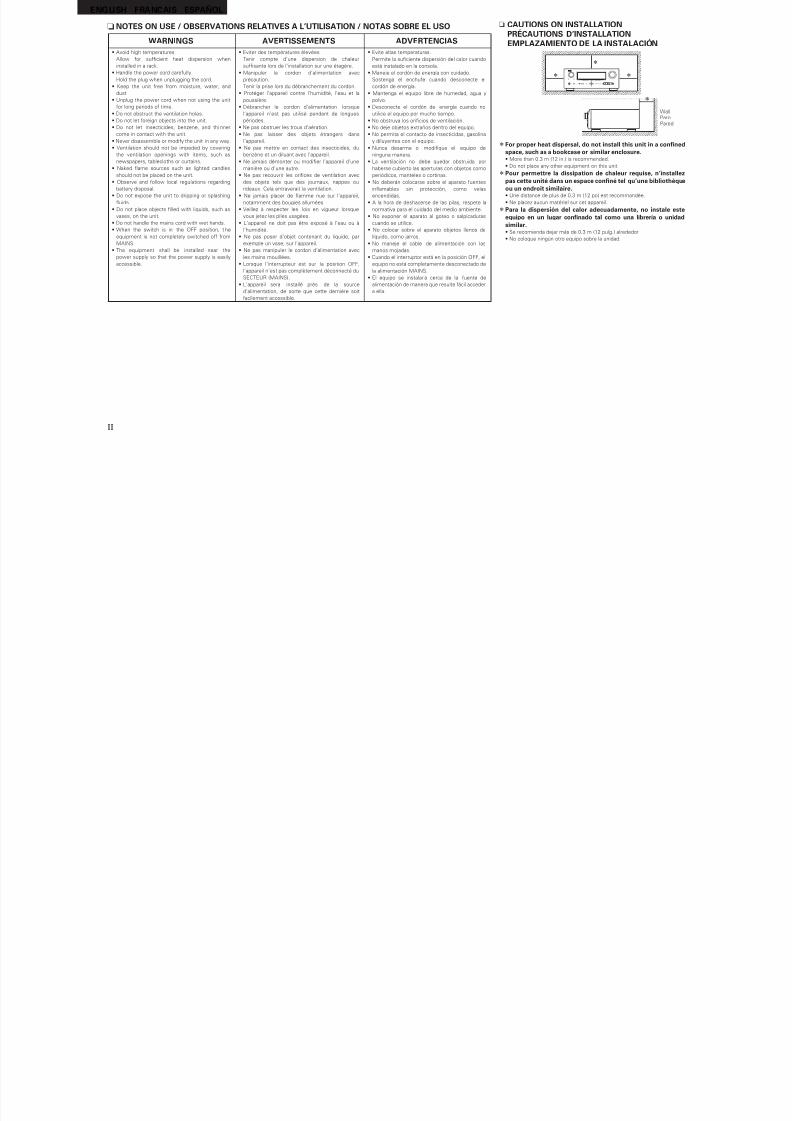
n CAUTIONS ON INSTALLATIONPRÉCAUTIONS D’INSTALLATIONEMPLAZAMIENTO DE LA INSTALACIÓN
z z
z
WallParoiPared
z
zFor proper heat dispersal, do not install this unit in a confnedspace, such as a bookcase or similar enclosure.• More than 0.3 m (12 in.) is recommended.
• Do not place any other equipment on this unit.
zPour permettre la dissipation de chaleur requise, n’installezpas cette unité dans un espace confné tel qu’une bibliothèqueou un endroit similaire.• Une distance de plus de 0.3 m (12 po) est recommandée.
• Ne placez aucun matériel sur cet appareil.
zPara la dispersión del calor adecuadamente, no instale esteequipo en un lugar confnado tal como una librería o unidad
similar.• Se recomienda dejar más de 0.3 m (12 pulg.) alrededor.
• No coloque ningún otro equipo sobre la unidad.
8/7/2019 IBJSC.com | I-WEB.com.vn - 953467670
http://slidepdf.com/reader/full/ibjsccom-i-webcomvn-953467670 5/92
1
ENGLISH
B
a s i c v e r s i o n
A d v a n
c e d v e r s i o n
S i m p l e v e r s i o n
I n f o r m a t i o n
Thank you or purchasing this DENON product. To ensure proper operation, please read these owner’s manual careully beore using the product.
Ater reading them, be sure to keep them or uture reerence.
Getting started
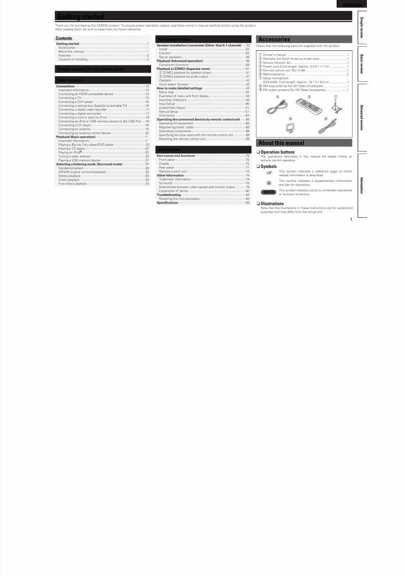
AccessoriesCheck that the ollowing parts are supplied with the product.
q Owner’s manual ...................................................................... 1
w Warranty (or North Ameri ca model only) ................................1
e Service network list .................................................................1
r Power cord (Cord length: Approx. 5.6 t / 1.7 m) ....................1
t Remote control unit (RC-1146) ................................................1
y R6/AA batteries .......................................................................2
u Setup microphone
(DM-A409, Cord length: Approx. 19.7 t / 6.0 m) .................... 1
i AM loop antenna (or HD Radio broadcasts) ........................... 1
o FM indoor antenna (or HD Radio broadcasts) ........................1
tr
i o
u
About this manual
n Operation buttonsThe operations described in this manual are based mainly on remote control operation.
n Symbols
v This symbol indicates a reerence page on whichrelated inormation is described.
This symbol indicates a supplementary inormation
and tips or operations.
NOTE This symbol indicates points to remember operations
or unction limitations.
n IllustrationsNote that the illustrations in these instructions are or explanation
purposes and may dier rom the actual unit.
Simple version (Simple setup guide) ··························3
Basic version··········································································12
Connections ·················································································13
Important inormati on ·································································13
Connecting an HDMI-compatible device ····································14
Connecting a TV··········································································15
Connecting a DVD player ····························································16
Connecting a set-top box (Satellite tuner/cable TV) ····················16
Connecting a digital video recorder ············································17
Connecting a digital camcorder ··················································17
Connecting a control dock or iPod ·············································18
Connecting an iPod or USB memory device to the USB Port ····18
Connecting a CD player ······························································19
Connecting an antenna ·······························································19
Connecting an external control device········································20
Playback (Basic operation) ·························································21
Important inormati on ·································································21
Playing a Blu-ray Disc player/DVD player ····································22
Playing a CD player ·····································································22
Playing an iPod®·········································································22
Tuning in radio stations ·······························································25
Playing a USB memory device····················································27
Selecting a listening mode (Surround mode) ··························28
Standard pl ayback ·······································································28
DENON original surround playback ·············································30Stereo playback ··········································································30
Direct playback ···········································································30
Pure direct playback····································································30
Advanced version ·······························································31
Speaker installation/connection (Other than 5.1-channel)·····32
Install ··························································································32
Connect ······················································································33
Set up speakers ··········································································36Playback (Advanced operation) ·················································38
Convenient unctions ··································································38
Playback in ZONE2 (Separate room) ········································41
q ZONE2 playback by speaker output ·······································41
w ZONE2 playback by audio output ···········································41
Playback ······················································································42
Quick select unction ··································································42
How to make detailed settings··················································43
Menu map ··················································································43
Examples o menu and ront display ··········································44
Inputting characters ···································································45
Input Setup ·················································································46
Audio/Video Adjust ·····································································51
Manual Setup··············································································57
Inormation ·················································································64Operating the connected devices by remote control unit ······65
Operating AV equipment ····························································65
Registering preset codes ····························································65
Operating components ·······························································68
Speciying the zone used with the remote control unit ··············69
Resetting the remote control unit···············································69
Inormation·············································································69
Part names and unctions···························································70
Front panel ··················································································70
Display ························································································70
Rear panel ···················································································71
Remote control unit ····································································72Other inormation ·······································································74
Trademark inormation································································74
Surround ·····················································································75
Relationship between video signals and monitor output ············79
Explanation o terms ···································································80
Troubleshooting ··········································································82
Resetting the microprocessor ····················································84
Specifcations··············································································84
ContentsGetting started ··············································································1
Accessories ··················································································1
About this manual ·········································································1
Features ························································································2
Cautions on handling ····································································2
8/7/2019 IBJSC.com | I-WEB.com.vn - 953467670
http://slidepdf.com/reader/full/ibjsccom-i-webcomvn-953467670 6/92
2
ENGLISH
Cautions on handling
• Beore turning the power switch onCheck once again that all connections are correct and that there are
no problems with the connection cables.
• Power is supplied to some o the circuitry even when the unit is
set to the standby mode. When going on vacation or leaving home
or long periods o time, be sure to unplug the power cord rom the
power outlet.
• About CondensationI there is a major dierence in temperature between the inside o
the unit and the surroundings, condensation (dew) may orm on
the operating parts inside the unit, causing the unit not to operate
properly.
I this happens, let the unit sit or an hour or two with the power
turned o and wait until there is little dierence in temperature
beore using the unit.
• Cautions on using mobile phonesUsing a mobile phone near this unit may result in noise. I that
occurs, move the mobile phone away rom this unit when it is in use.
• Moving the unitTurn o the power and unplug the power cord rom the power
outlet. Next, disconnect the connection cables to other system units
beore moving the unit.
• About Care• Wipe the cabinet and control panel clean with a sot cloth.
• Follow the instructions when using a chemical cleaner.
• Benzene, paint thinner or other organi c solvents as well as
insecticide may cause material changes and discoloration i brought
into contact with the unit, and should thereore not be used.
Features
Fully Discrete, identical quality and power or all7 channels (135 W x 7ch)The unit is equipped with a power amplifer that reproduces high-
fdelity sound in surround mode with equal quality and power or all
channels, true to the original sound.
The power amplifer circuit adopts a discrete-circuit confguration
that achieves high-quality surround sound reproduction.
Supports HDMI 1.4 with 3D, ARC, Deep Color,x.v.Color , Auto Lipsync and HDMI control unctionThis unit can output 3D video signals input rom a Blu-ray Disc
player to a TV that supports a 3D system. This unit also supports
the ARC (Audio Return Channel) unction, which reproduces TV
sound with this unit via an HDMI cable used or connecting the
unit and a TVz.
z The TV should support the ARC unction.
6-HDMI inputs and 1-outputThe unit is equipped with 6 HDMI input connectors or connecting
devices with HDMI connectors, such as a Blu-ray Disc player,game machine, HD video camera, etc.
High defnition audio supportThe unit is equipped with a decoder which supports high-quality
digital audio ormat or Blu-ray Disc players such as Dolby TrueHD,
DTS-HD Master Audio, etc.
Dolby Pro Logic gzThe unit is provided with a Dolby Pro Logic gz decoder. When you
reproduce the sound in Dolby Pro Logic gz playback with ront
height speakers connected to the unit, you can enjoy playback
sound with rich spacial expression.
Easy to use, Graphical User InteraceSimple settings are enabled with the setting menus displayed on
the TV screen. When you control the sound volume, the volume
level is displayed on the screen, and when you switch the input
source, the name o the input source is displayed.
Auto setup unctionThe unit is provided with an “Auto setup unction” which
automatically makes speaker settings best suited or the listening
environment. The sound rom the speakers is picked up with the
supplied microphone. Reecting sound and audio characteristics o
speakers are measured, and settings or an optimum sound feld
are automatically made.
All sources are up-scaled to 1080pThe unit is provided with an HDMI video upscaling unction that
converts an analog video signal input to the unit to a 1080p (HD
resolution) signal and supplies it to a TV via the HDMI connector.
This enables the unit and a TV connected with a single HDMI cable
and any video source to be reproduced precisely with HD level o
quality.
Direct play or iPod® and iPhone® via USBMusic data rom an iPod can be played back i you connect the
USB cable supplied with the iPod via the USB port o this unit, and
also an iPod can be controlled with the remote control unit or this
unit.
When an iPod is connected, merely pressing iPod PLAY on the
main unit or remote control unit starts playback o music rom the
iPod.
8/7/2019 IBJSC.com | I-WEB.com.vn - 953467670
http://slidepdf.com/reader/full/ibjsccom-i-webcomvn-953467670 7/92
Simpleversion
3
ENGLISH
B
a s i c v e r s i o n
A d v a n
c e d v e r s i o n
I n f o r m a t i o n
S i m p l e v e r s i o n
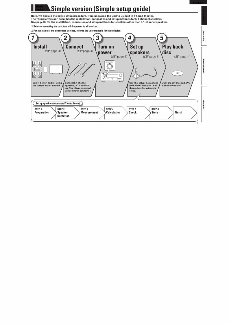
Simple version (Simple setup guide)Here, we explain the entire setup procedure, rom unboxing the unit to using it in a home theater.The “Simple version” describes the installation, connection and setup methods or 5.1-channel speakers.See page 32 or the installation, connection and setup methods or speakers other than 5.1-channel speakers.
nBefore connecting the unit, turn off the power to all devices.
n For operation of the connected devices, refer to the user manuals for each device.
Play backdisc
(vpage 11)
Enjoy Blu-ray Disc and DVDin surround sound.
5
Set upspeakers
(vpage 6)
Use the setup microphone(DM-A409) included withthe product, or automaticsetup.
4
Turn onpower
(vpage 6)
3
Connect(vpage 4)
Connect 5.1-channelspeakers, a TV and Blu-ray Disc player equippedwith an HDMI connector.
2
Install(vpage 4)
Enjoy better audio, usingthe correct install method.
1
Set up speakers (Audyssey® Auto Setup)
FinishSTEP 6
StoreSTEP 5
CheckSTEP 4
CalculationSTEP 3
MeasurementSTEP 2
SpeakerDetection
STEP 1
Preparation
8/7/2019 IBJSC.com | I-WEB.com.vn - 953467670
http://slidepdf.com/reader/full/ibjsccom-i-webcomvn-953467670 8/92
4
ENGLISH
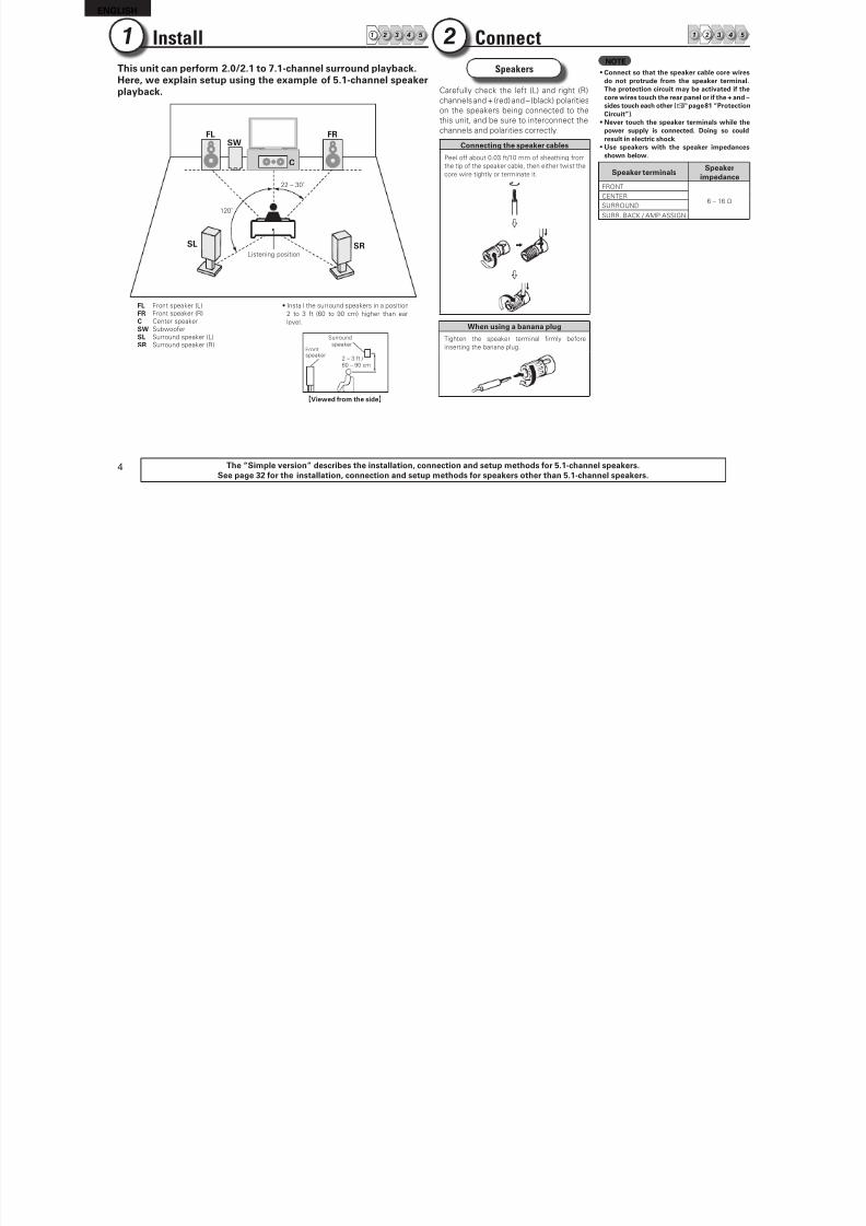
Speakers
Careully check the let (L) and right (R)
channels and + (red) and – (black) polarities
on the speakers being connected to the
this unit, and be sure to interconnect thechannels and polarities correctly.
Connecting the speaker cables
Peel o about 0.03 t/10 mm o sheathing rom
the tip o the speaker cable, then either twist the
core wire tightly or terminate it.
When using a banana plug
Tighten the speaker terminal frmly beore
inserting the banana plug.
NOTE• Connect so that the speaker cable core wires
do not protrude rom the speaker terminal.The protection circuit may be activated i thecore wires touch the rear panel or i the + and –sides touch each other (vpage 81 “ProtectionCircuit”).
• Never touch the speaker terminals while thepower supply is connected. Doing so couldresult in electric shock.
• Use speakers with the speaker impedancesshown below.
Speaker terminalsSpeaker
impedanceFRONT
6 – 16 ΩCENTER
SURROUND
SURR. BACK / AMP ASSIGN
Install 1 2 4 53
This unit can perorm 2.0/2.1 to 7.1-channel surround playback.Here, we explain setup using the example o 5.1-channel speakerplayback.
FL FR
SW
C
SL SR
120˚
22 – 30˚
Listening position
FL Front speaker (L) • Install the surround speakers in a position
2 to 3 t (60 to 90 cm) higher than ear
level.
Frontspeaker
Surroundspeaker
2 – 3 t / 60 – 90 cm
GViewed rom the sideH
FR Front speaker (R)
C Center speaker
SW Subwooer
SL Surround speaker (L)
SR Surround speaker (R)
1 Connect 1 2 4 532
The “Simple version” describes the installation, connection and setup methods or 5.1-channel speakers.See page 32 or the installation, connection and setup methods or speakers other than 5.1-channel speakers.
8/7/2019 IBJSC.com | I-WEB.com.vn - 953467670
http://slidepdf.com/reader/full/ibjsccom-i-webcomvn-953467670 9/92
5
ENGLISH
B
a s i c v e r s i o n
A d v a n
c e d v e r s i o n
I n f o r m a t i o n
S i m p l e v e r s i o n
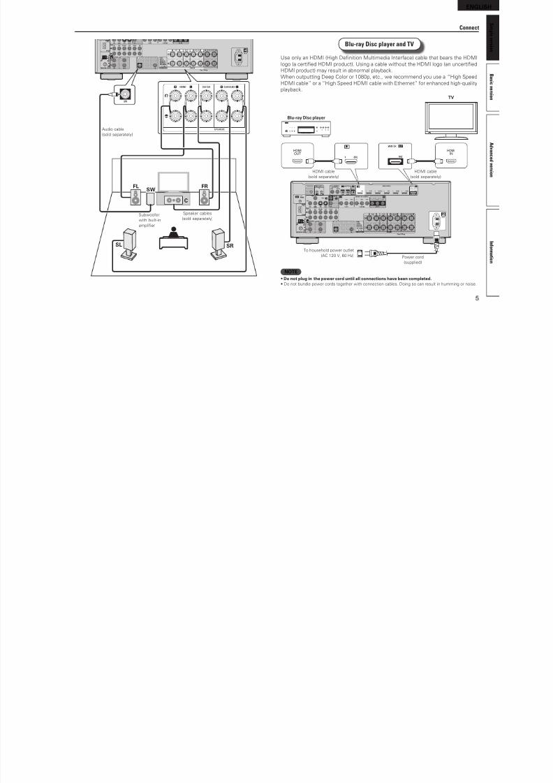
Blu-ray Disc player and TV
Use only an HDMI (High Defnition Multimedia Interace) cable that bears the HDMI
logo (a certifed HDMI product). Using a cable without the HDMI logo (an uncertifed
HDMI product) may result in abnormal playback.
When outputting Deep Color or 1080p, etc., we recommend you use a “High SpeedHDMI cable” or a “High Speed HDMI cable with Ethernet” or enhanced high-quality
playback.
INHDMI
OUTHDMI
To household power outlet
(AC 120 V, 60 Hz) Power cord
(supplied)
HDMI cable
(sold separately)
HDMI cable
(sold separately)
Blu-ray Disc player
TV
NOTE• Do not plug in the power cord until all connections have been completed.• Do not bundle power cords together with connection cables. Doing so can result in humming or noise.
Connect
FL FR
C
SL SR
SW
Speaker cables
(sold separately)
Audio cable
(sold separately)
Subwooer
with built-in
amplifer
8/7/2019 IBJSC.com | I-WEB.com.vn - 953467670
http://slidepdf.com/reader/full/ibjsccom-i-webcomvn-953467670 10/92
6
ENGLISH
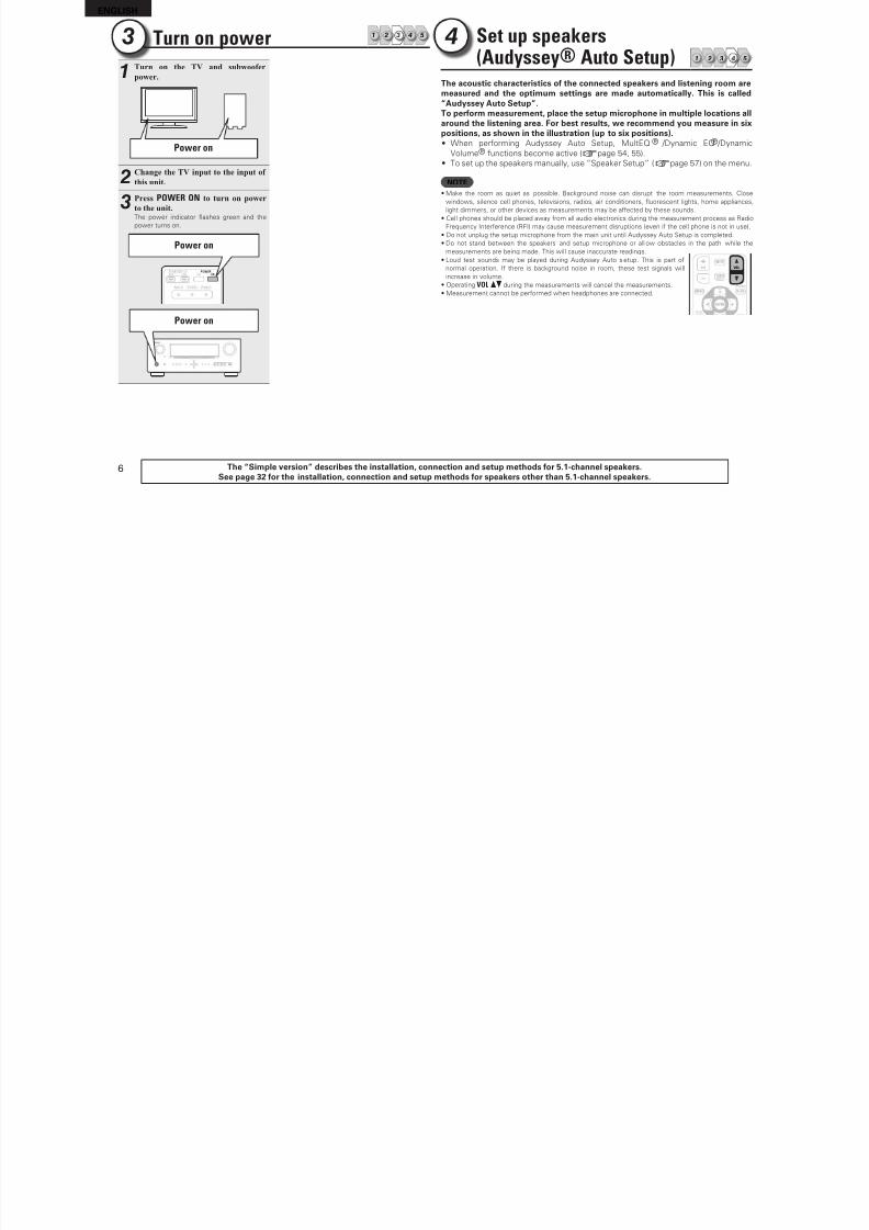
Set up speakers(Audyssey® Auto Setup) 1 2 4 53
4
The “Simple version” describes the installation, connection and setup methods or 5.1-channel speakers.See page 32 or the installation, connection and setup methods or speakers other than 5.1-channel speakers.
The acoustic characteristics o the connected speakers and listening room aremeasured and the optimum settings are made automatically. This is called“Audyssey Auto Setup”.To perorm measurement, place the setup microphone in multiple locations all
around the listening area. For best results, we recommend you measure in sixpositions, as shown in the illustration (up to six positions). • When perorming Audyssey Auto Setup, MultEQ® /Dynamic EQ® /Dynamic
Volume® unctions become active (vpage 54, 55).
• To set up the speakers manually, use “Speaker Setup” (vpage 57) on the menu.
NOTE• Make the room as quiet as possible. Background noise can disrupt the room measurements. Close
windows, silence cell phones, televisions, radios, air conditioners, uorescent lights, home appliances,
light dimmers, or other devices as measurements may be aected by these sounds.
• Cell phones should be placed away rom all audio electronics during the measurement process as Radio
Frequency Intererence (RFI) may cause measurement disruptions (even i the cell phone is not in use).
• Do not unplug the setup microphone rom the main unit until Audyssey Auto Setup is completed.
• Do not stand between the speakers and setup microphone or all ow obstacles in the path while the
measurements are being made. This will cause inaccurate readings.
• Loud test sounds may be played during Audyssey Auto setup. This is part o
normal operation. I there is background noise in room, these test signals will
increase in volume.
• Operating VOL df during the measurements will cancel the measurements.
• Measurement cannot be perormed when headphones are connected.
Turn on power 1 2 4 533
1Turn on the TV and subwoofer
power.
Power on
2Change the TV input to the input of
this unit.
3Press POWER ON to turn on power
to the unit.The power indicator ashes green and the
power turns on.
Power on
Power on
8/7/2019 IBJSC.com | I-WEB.com.vn - 953467670
http://slidepdf.com/reader/full/ibjsccom-i-webcomvn-953467670 11/92
7
ENGLISH
B
a s i c v e r s i o n
A d v a n
c e d v e r s i o n
I n f o r m a t i o n
S i m p l e v e r s i o n
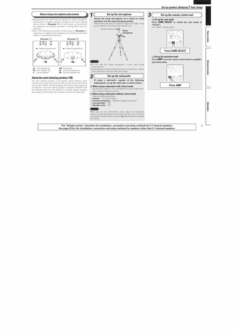
About setup microphone placement
• Measurements are perormed by placing the setup microphone
successively at multiple positions throughout the entire listening
area, as shown in GExample qH. For best results, we recommend
you measure in six positions, as shown in the illustration (up to six
positions).
• Even i the listening environment is small as shown inGExample wH,
measuring at multiple points throughout the listening environmentresults in more eective correction.
FL SW C FR
SRSL *M
FL SW C FR
SRSL *M
( : Measuring positions)
GExample qH GExample wH
( : Measuring positions)
FL Front speaker (L) SW Subwooer
FR Front speaker (R) SL Surround speaker (L)
C Center speaker SR Surround speaker (R)
About the main listening position (*M)The main listening position is the position where listeners would
normally sit or where one would normally sit alone within the listening
environment. Beore starting Audyssey Auto Setup, place the setup
microphone in the main listening position. Audyssey MultEQ® uses
the measurements rom this position to calculate speaker distance,
level, polarity, and the optimum crossover value or the subwooer.
The “Simple version” describes the installation, connection and setup methods or 5.1-channel speakers.See page 32 or the installation, connection and setup methods or speakers other than 5.1-channel speakers.
Set up speakers (Audyssey® Auto Setup)
3 Set up the remote control unit
n Set up the zone modePress ZONE SELECT to switch the zone mode to
“MAIN”.The “MAIN” indicator lights.
Press ZONE SELECT
n Set up the operation modePress AMP to set the remote control unit to amplier
operation mode.
Press AMP
1 Set up the microphone
Mount the setup microphone on a tripod or stand
and place it in the main listening position.When placing the setup microphone, adjust the height o the
sound receptor to the level o the listener’s ear.
Sound receptorSetup
microphone
NOTE• Do not hold the setup microphone in your hand during
measurements.• Avoid placing the setup microphone close to a seat back or wall as
sound reections may give inaccurate results.
2 Set up the subwoofer
If using a subwoofer capable of the following
adjustments, set up the subwoofer as shown below.
n When using a subwoofer with a direct modeSet the direct mode to “On” and disable the volume adjustment
and crossover requency setting.
n When using a subwoofer without a direct modeMake the ollowing settings:
• Volume : “12 o’clock position”
• Crossover requency : “Maximum/Highest Frequency”
• Low pass flter : “O”
• Standby mode : “O”
NOTEWhen you use two subwooers, please adjust the subwooer
volume controls individually so that each subwooer level is as close
as possible to 75 dB using the test tone (vpage 59) beore Audyssey
Auto Setup.
8/7/2019 IBJSC.com | I-WEB.com.vn - 953467670
http://slidepdf.com/reader/full/ibjsccom-i-webcomvn-953467670 12/92
8
ENGLISH
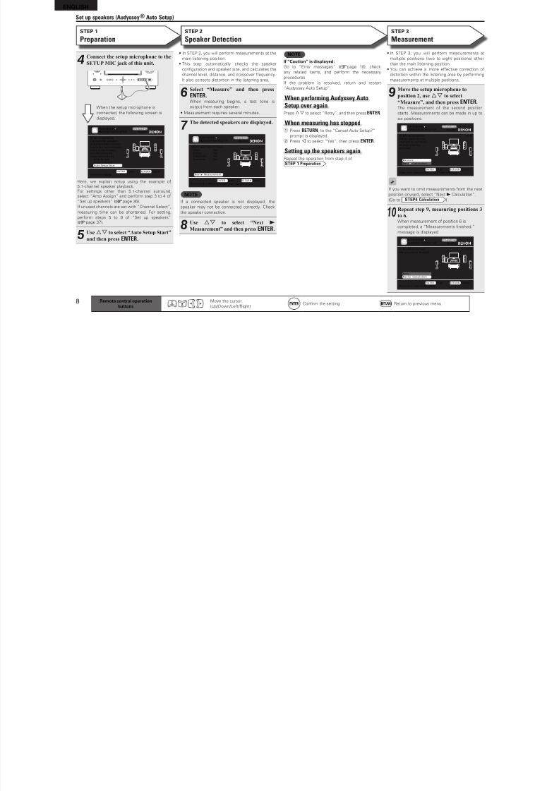
• In STEP 2, you will perorm measurements at the
main listening position.
• This step automatically checks the speaker
confguration and speaker size, and calculates the
channel level, distance, and crossover requency.
It also corrects distortion in the listening area.
6Select “Measure” and then press
ENTER.When measuring begins, a test tone is
output rom each speaker.
• Measurement requires several minutes.
7The detected speakers are displayed.
[2/6]STEP2 Spkr Detect Check
Go to Step 3 (Measurement) after speaker check
Retry
Next Measurement
Front
Center
Subwoofer
Surround
Yes
Yes
Yes
Yes
AUTO SETUP
AUDYSSEY AUTO SETUP MultEQ
ENTER Enter RETURN Cancel
NOTEI a connected speaker is not displayed, the
speaker may not be connected correctly. Check
the speaker connection.
8Use ui to select “Next 1
Measurement” and then press ENTER.
• In STEP 3, you will perorm measurements at
multiple positions (two to eight positions) other
than the main listening position.
• You can achieve a more eective correction o
distortion within the listening area by perorming
measurements at multiple positions.
9Move the setup microphone to
position 2, use ui to select
“Measure”, and then press ENTER.The measurement o the second position
starts. Measurements can be made in up to
six positions.
[3/6]STEP3 Measurement
Please place the mic-
rophone at ear height
at 2nd listening
position.
Start next measurement. Test Tone will start
AUTO SETUP
AUDYSSEY AUTO SETUP MultEQ
ENTER Enter RETURN Cancel
Measure
Next Calculation
I you want to omit measurements rom the next
position onward, select “Next 1 Calculation”.
(Go to STEP4 Calculation )
10Repeat step 9, measuring positions 3
to 6.When measurement o position 6 is
completed, a “Measurements fnished.”
message is displayed.
[3/6]STEP3 Measurement
Measurements finished.
Proceed to Step 4 (Analyze)
AUTO SETUP
AUDYSSEY AUTO SETUP MultEQ
ENTER Enter RETURN Cancel
Retry
Next Calculation
Set up speakers (Audyssey® Auto Setup)
STEP 1
Preparation
4Connect the setup microphone to the
SETUP MIC jack of this unit.
[1/6]STEP1 PreparationConnect the speakersand place them accord-ing to the recommenda-tions in the manual.Set the followingitems if necessary.
Start Auto Setup
Amp AssignChannel SelectAuto Setup Start
AUTO SETUPAUDYSSEY AUTO SETUP MultEQ
ENTER Enter RETURN Cancel
When the setup microphone is
connected, the ollowing screen is
displayed.
Here, we explain setup using the example o5.1-channel speaker playback.For settings other than 5.1-channel surround,select “Amp Assign” and perorm step 3 to 4 o
“Set up speakers” (vpage 36).
I unused channels are set with “Channel Select”,
measuring time can be shortened. For setting,
perorm steps 5 to 9 o “Set up speakers”(vpage 37).
5
Use ui to select “Auto Setup Start”
and then press ENTER.
NOTEI “Caution” is displayed:Go to “Error messages” (vpage 10), check
any related items, and perorm the necessary
procedures.
I the problem is resolved, return and restart
“Audyssey Auto Setup”.
When performing Audyssey AutoSetup over againPressui to select “Retry”, and then press ENTER.
When measuring has stoppedq Press RETURN, to the “Cancel Auto Setup?”
prompt is displayed.
w Press o to select “Yes”, then press ENTER.
Setting up the speakers again
Repeat the operation rom step 4 oSTEP 1 Preparation .
Remote control operationbuttons
Move the cursor
(Up/Down/Let/Right)Confrm the setting Return to previous menu
STEP 2
Speaker DetectionSTEP 3
Measurement
8/7/2019 IBJSC.com | I-WEB.com.vn - 953467670
http://slidepdf.com/reader/full/ibjsccom-i-webcomvn-953467670 13/92
9
ENGLISH
B
a s i c v e r s i o n
A d v a n
c e d v e r s i o n
I n f o r m a t i o n
S i m p l e v e r s i o n
Set up speakers (Audyssey® Auto Setup)
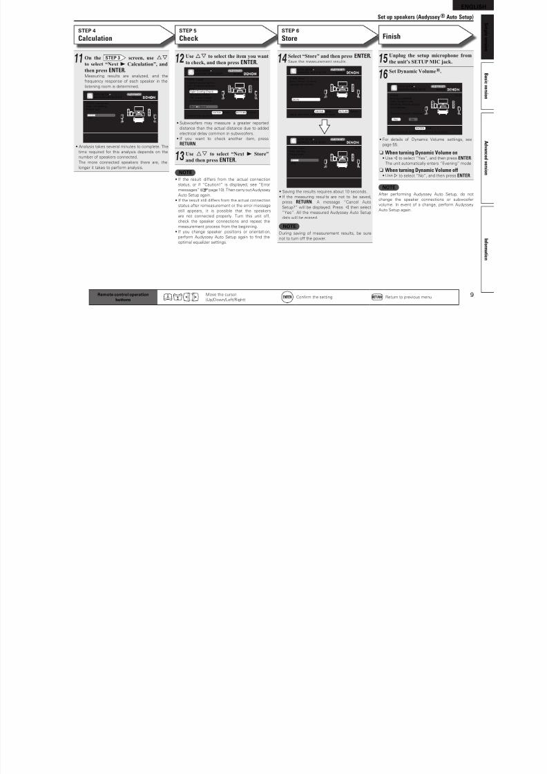
STEP 4
CalculationSTEP 5
Check
11 On the STEP 3 screen, use ui
to select “Next 1 Calculation”, and
then press ENTER.Measuring results are analyzed, and the
requency response o each speaker in the
listening room is determined.
[4/6]
AUTO SETUP
AUDYSSEY AUTO SETUP MultEQ
STEP4 Calculation
Now calculating...
Please wait.
25%
• Analysis takes several minutes to complete. The
time required or this analysis depends on the
number o speakers connected.
The more connected speakers there are, the
longer it takes to perorm analysis.
Remote control operationbuttons
Move the cursor
(Up/Down/Let/Right)Confrm the setting Return to previous menu
NOTE• I the result diers rom the actual connection
status, or i “Caution!” is displayed, see “Error
messages” (vpage 10). Then carry out Audyssey
Auto Setup again.
• I the result still diers rom the actual connection
status ater remeasurement or the error message
still appears, it is possible that the speakers
are not connected properly. Turn this unit o,
check the speaker connections and repeat the
measurement process rom the beginning.
• I you change speaker positions or orientati on,perorm Audyssey Auto Setup again to fnd the
optimal equalizer settings.
12Use ui to select the item you want
to check, and then press ENTER.
[5/6]STEP5 CheckCheck processing res-ults. To proceed,press“Next”
Select item to check
Spkr Config CheckDistance CheckCh. L evel CheckCrossover Check
Next Store
AUTO SETUPAUDYSSEY AUTO SETUP MultEQ
ENTER Enter RETURN Cancel
• Subwooers may measure a greater reported
distance than the actual distance due to added
electrical delay common in subwooers.
• I you want to check another item, press
RETURN.
13Use ui to select “Next 1 Store”and then press ENTER.
STEP 6
Store
14Select “Store” and then press ENTER.Save the measurement results.
[6/6]
AUTO SETUP
AUDYSSEY AUTO SETUP MultEQ
STEP6 Store
Now storing...
Please wait.
25%
[6/6]STEP6 StorePress “Store” to store
calculation results.
Apply and store measurement result
Store
AUTO SETUP
AUDYSSEY AUTO SETUP MultEQ
ENTER Enter RETURN Cancel
• Saving the results requires about 10 seconds.
• I the measuring resul ts are not to be saved,
press RETURN. A message “Cancel Auto
Setup?” will be displayed. Press o then select
“Yes”. All the measured Audyssey Auto Setup
data will be erased.
NOTE
During saving o measurement results, be surenot to turn o the power.
Finish
NOTEAter perorming Audyssey Auto Setup, do not
change the speaker connections or subwooer
volume. In event o a change, perorm Audyssey
Auto Setup again.
15Unplug the setup microphone from
the unit’s SETUP MIC jack.
16
Set Dynamic Volume®.
[6/6]FinishStoring complete.Auto Setup is nowfinished. Please unplugmicrophone.
Turn on Dynamic Volume?
AUTO SETUPAUDYSSEY AUTO SETUP MultEQ
ENTER Exit
Turn Dynamic Volume on and exit Auto Setup
Yes No
• For details o Dynamic Volume settings, see
page 55.
n When turning Dynamic Volume on• Use o to select “Yes”, and then press ENTER.
The unit automatically enters “Evening” mode.
n When turning Dynamic Volume off• Use p to select “No”, and then press ENTER.
8/7/2019 IBJSC.com | I-WEB.com.vn - 953467670
http://slidepdf.com/reader/full/ibjsccom-i-webcomvn-953467670 14/92
10
ENGLISH
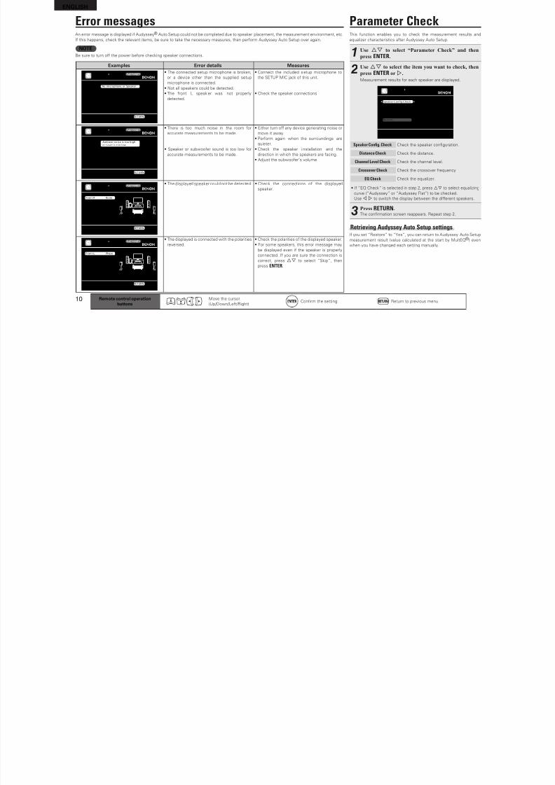
Parameter CheckThis unction enables you to check the measurement results and
equalizer characteristics ater Audyssey Auto Setup.
1Use ui to select “Parameter Check” and then
press ENTER.
2Use ui to select the item you want to check, then
press ENTER or p.
Measurement results or each speaker are displayed.
Speaker Config CheckDistance CheckChannel Level CheckCrossover CheckEQ Check
Restore
AUTO SETUPPARAMETER CHECK
Show speaker configuration result
Speaker Cong. Check
Distance Check
Channel Level Check
Crossover Check
EQ Check
Check the speaker confguration.
Check the distance.
Check the channel level.
Check the crossover requency.
Check the equalizer.
• I “EQ Check” is selected in step 2, press ui to select equalizing
curve (“Audyssey” or “Audyssey Flat”) to be checked.
Use o p to switch the display between the dierent speakers.
3Press RETURN.The confrmation screen reappears. Repeat step 2.
Retrieving Audyssey Auto Setup settings
I you set “Restore” to “Yes”, you can return to Audyssey Auto Setupmeasurement result (value calculated at the start by MultEQ®) even
when you have changed each setting manually.
Error messagesAn error message is displayed i Audyssey® Auto Setup could not be completed due to speaker placement, the measurement environment, etc.
I this happens, check the relevant items, be sure to take the necessary measures, then perorm Audyssey Auto Setup over again.
NOTEBe sure to turn o the power beore checking speaker connections.
Examples Error details Measures
Caution!
No microphone or Speaker
Retry
Check cause of problem!
AUTO SETUP
AUDYSSEY AUTO SETUP MultEQ
RETURN Cancel
• The connected setup microphone is broken,
or a device other than the supplied setupmicrophone is connected.
• Not all speakers could be detected.
• The ront L speaker was not properly
detected.
• Connect the included setup microphone to
the SETUP MIC jack o this unit.
• Check the speaker connections.
Caution!Ambient noise is too highor Level is too low
Retry
Check cause of problem!
AUTO SETUPAUDYSSEY AUTO SETUP MultEQ
RETURN Cancel
• There is too much noise in the room or
accurate measurements to be made.
• Speaker or subwooer sound is too low or
accurate measurements to be made.
• Either turn o any device generating noise or
move it away.
• Perorm again when the surroundings are
quieter.
• Check the speaker i nstallation and the
direction in which the speakers are acing.
• Adjust the subwooer’s volume.
Caution!
Check cause of problem!
Retry
Front R None
AUTO SETUP
AUDYSSEY AUTO SETUP MultEQ
RETURN Cancel
• The displayed speaker could not be detected. • Check the connections o the displayed
speaker.
Caution!
Check cause of problem!
Retry
Skip
Front L Phase
AUTO SETUP
AUDYSSEY AUTO SETUP MultEQ
RETURN Cancel
• The displayed is connected with the polarities
reversed.
• Check the polarities o the displayed speaker.
• For some speakers, this error message may
be displayed even i the speaker is properly
connected. I you are sure the connection is
correct, press ui to select “Skip”, then
press ENTER.
Remote control operationbuttons
Move the cursor
(Up/Down/Let/Right)Confrm the setting Return to previous menu
ENG ISH
8/7/2019 IBJSC.com | I-WEB.com.vn - 953467670
http://slidepdf.com/reader/full/ibjsccom-i-webcomvn-953467670 15/92
11
ENGLISH
B
a s i c v e r s i o n
A d v a n
c e d v e r s i o n
I n f o r m a t i o n
S i m p l e v e r s i o n
Play back disc 1 2 4 535
Remote control operationbuttons
Move the cursor
(Up/Down/Let/Right)Confrm the setting Return to previous menu
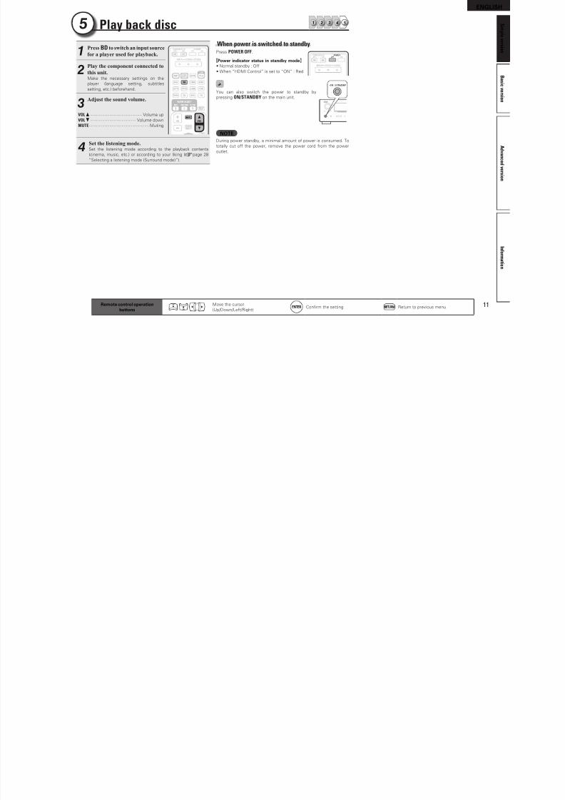
1Press BD to switch an input source
for a player used for playback.
2Play the component connected to
this unit.Make the necessary settings on the
player (language setting, subtitles
setting, etc.) beorehand.
3Adjust the sound volume.
VOL d ··········································· Volume up
VOL f ······································ Volume down
MUTE·················································· Muting
4Set the listening mode.Set the listening mode according to the playback contents
(cinema, music, etc.) or according to your liking (vpage 28
“Selecting a listening mode (Surround mode)”).
When power is switched to standbyPress POWER OFF.
GPower indicator status in standby modeH• Normal standby : O
• When “HDMI Control” is set to “ON” : Red
You can also switch the power to standby by
pressing ON/STANDBY on the main unit.
NOTEDuring power standby, a minimal amount o power is consumed. To
totally cut o the power, remove the power cord rom the power
outlet.
ENGLISH
8/7/2019 IBJSC.com | I-WEB.com.vn - 953467670
http://slidepdf.com/reader/full/ibjsccom-i-webcomvn-953467670 16/92
Basicversion
12
ENGLISH
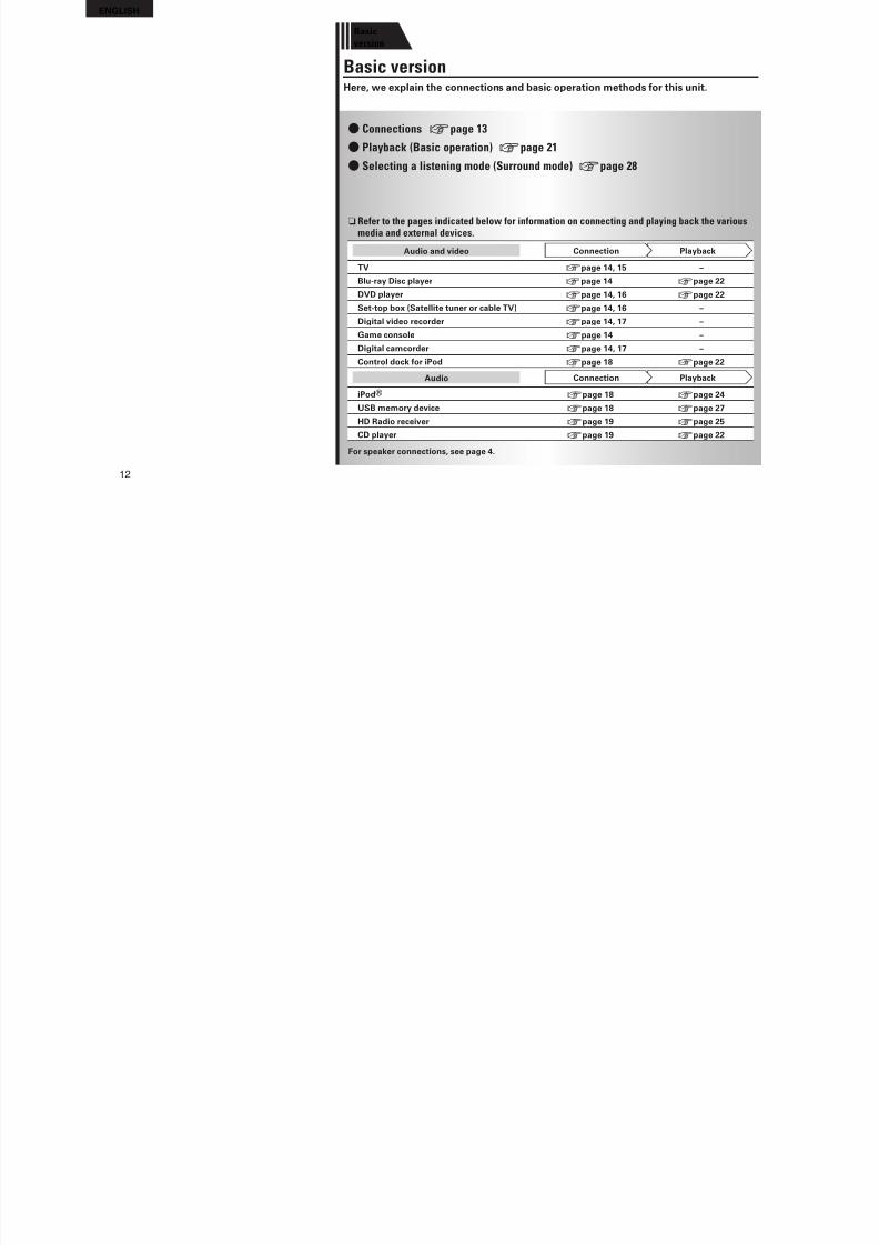
F Connections vpage 13
F Playback (Basic operation) vpage 21
F Selecting a listening mode (Surround mode) vpage 28
n Refer to the pages indicated below for information on connecting and playing back the variousmedia and external devices.
Audio and video PlaybackConnectionTV vpage 14, 15 –
Blu-ray Disc player vpage 14 vpage 22
DVD player vpage 14, 16 vpage 22
Set-top box (Satellite tuner or cable TV) vpage 14, 16 –
Digital video recorder vpage 14, 17 –
Game console vpage 14 –
Digital camcorder vpage 14, 17 –
Control dock or iPod vpage 18 vpage 22
Audio PlaybackConnection
iPod® vpage 18 vpage 24
USB memory device vpage 18 vpage 27
HD Radio receiver vpage 19 vpage 25
CD player vpage 19 vpage 22
For speaker connections, see page 4.
Basic versionHere, we explain the connections and basic operation methods or this unit.
ENGLISH
8/7/2019 IBJSC.com | I-WEB.com.vn - 953467670
http://slidepdf.com/reader/full/ibjsccom-i-webcomvn-953467670 17/92
13
ENGLISH
A d v a n c e d v e r s i o n
S i m p l e v e r s i o n
I n f o r m a t i o n
B
a s i c v e r s i o n
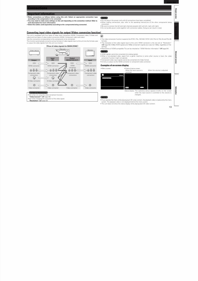
Converting input video signals for output (Video conversion function)This unit is equipped with our types o video input connectors (HDMI, Component video, S-Video and
video) and two types o video output connectors (HDMI, Component video and video).
Use the connectors corresponding to the components to be connected.
This unction automatically converts va rious ormats o video signals input to this unit into the ormats used
to output the video signals rom this unit to a monitor.
GFlow o video signals or MAIN ZONEH
HDMI connector
Component video
connectors
S-Video connector
Video connector
Monitor
HDMI connector
Component video
connectors
Component video
connectors
Component video
connectors
S-Video connector
Video connector
HDMI
connector
Video connector
HDMI connector
Video connector
Video deviceThis unit
OutputInput(IN)
Output(MONITOR OUT) Input
• Set when not using the video conversion unction.
“Video Convert” (vpage 49)
• Set when changing the resolution o the video signal.
“Resolution” (vpage 50)
in Set as Necessary
Connections
• The video conversion unction supports the NTSC, PAL, SECAM, NTSC 4.43, PAL-N, PAL-M and PAL-60
ormats.
• The resolution o the video signal input to this unit’s HDMI connector is the one set at “Resolution”
(vpage 50) (1080p HDMI signals and 1080p component signals are output at 1080p, regardless o the
setting).
• Resolutions o HDMI-compatible TVs can be checked at “HDMI Monitor Inormation” (vpage 64).
NOTE• HDMI signals cannot be converted into analog signals.
• When a non-standard video signal rom a game machine or some other source is input, the videoconversion unction might not operate.
• Component video input signals cannot be converted into Video ormat.
• A menu is output via the HDMI connector or component video connector.
Examples of on-screen display
• Menu screen • Status display screen
When the input source is
switched
When the volume is adjusted
Adjust various audio and video parameters
Audio/Video Adjust
InformationAuto SetupManual Setup
Input Setup
MENU
Input Auto
STEREO
BD
Mode
Master Volume -80.0dB
Status display: The operating sta tus appears br iey on the screen
when the input source is switched or the volume is
changed.
NOTE• I you operate the menu while playing back 3D vi deo content, the playback video is replaced by the menu
screen. The playback video is not displayed behind the menu screen.
• This unit does not show the status display while playing back 3D video content.
Important information• Make connections as ollows beore using this unit. Select an appropriate connection type
according to the components to be connected.• You may need to make some settings on this unit depending on the connection method. Reer to
each description or more inormation.• Select the cables (sold separately) according to the components being connected.
NOTE• Do not plug in the power cord until all connections have been completed.
• When making connections, also reer to the operating instructi ons o the other components being
connected.
• Be sure to connect the let and right channels properly (let with let, right with right).
• Do not bundle power cords together with connection cables. Doing so can result in noise.
ENGLISH
8/7/2019 IBJSC.com | I-WEB.com.vn - 953467670
http://slidepdf.com/reader/full/ibjsccom-i-webcomvn-953467670 18/92
14
ENGLISH
About ARC (Audio return channel) functionThe Audio Return Channel in HDMI 1.4 enables a TV, via a single HDMI cable, to send audio data
“upstream” to this unit.
NOTE• To enable the ARC unction, set “HDMI Control” to “ON” (vpage 60).
• When connecting a TV that does not support the ARC unction, a separate audio cable is required. In this
case, reer to “Connecting a TV” (vpage 15) or the connection method.
About Content TypeThe HDMI Specifcation Version 1.4 enables simple, automated picture setting selection with no user
intervention.
NOTETo enable the Content Type, set “Video Mode” to “Auto” (vpage 49).
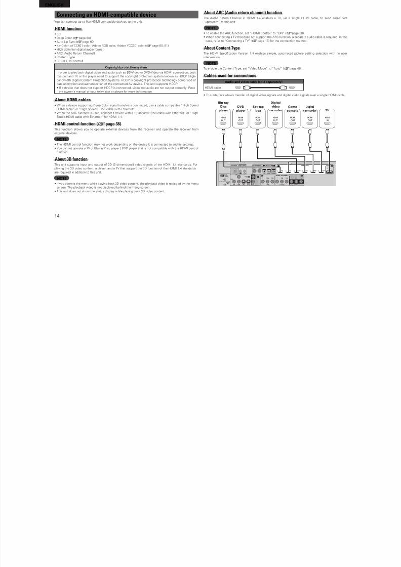
Cables used for connections
Audio and video cable (sold separately)
HDMI cable
• This interace allows transer o digital video signals and digital audio signals over a single HDMI cable.
OUT
HDMI
OUT
HDMI
OUT
HDMI
OUT
HDMI
OUT
HDMI
OUT
HDMI
IN
HDMI
Blu-rayDisc
playerDVD
player TVSet-top
boxDigital
camcorder
Digitalvideo
recorderGame
console
Connecting an HDMI-compatible deviceYou can connect up to fve HDMI-compatible devices to the unit.
HDMI function• 3D
• Deep Color (vpage 80)
• Auto Lip Sync (vpage 60)
• x.v.Color, sYCC601 color, Adobe RGB color, Adobe YCC601color (vpage 80, 81)
• High defnition digital audio ormat
• ARC (Audio Return Channel)
• Content Type• CEC (HDMI control)
Copyright protection system
In order to play back digital video and audio such as BD-Video or DVD-Video via HDMI connection, both
this unit and TV or the player need to support the copyright protection system known as HDCP (High-
bandwidth Digital Content Protection System). HDCP is copyright protection technology comprised o
data encryption and authentication o the connected AV device. This unit supports HDCP.
• I a device that does not support HDCP is connected, video and audio are not output correctly. Read
the owner’s manual o your television or player or more inormation.
About HDMI cables• When a device supporting Deep Color signal transer is connected, use a cable compatible “High Speed
HDMI cable” or “High Speed HDMI cable with Ethernet”
• When the ARC unction is used, connect a device with a ”Standard HDMI cable with Ethernet” or “HighSpeed HDMI cable with Ethernet” or HDMI 1.4.
HDMI control function (vpage 38)This unction allows you to operate external devices rom the receiver and operate the receiver rom
external devices.
NOTE• The HDMI control unction may not work depending on the device it is connected to and its settings.
• You cannot operate a TV or Blu-ray Disc player / DVD player that is not compatible with the HDMI control
unction.
About 3D functionThis unit supports input and output o 3D (3 dimensional) video signals o the HDMI 1.4 standards. For
playing the 3D video content, a player, and a TV that support the 3D unction o the HDMI 1.4 standards
are required in addition to this unit.
NOTE• I you operate the menu while playing back 3D video content, t he playback video is replaced by the menu
screen. The playback video is not displayed behind the menu screen.
• This unit does not show the status display while playing back 3D video content.
ENGLISH
8/7/2019 IBJSC.com | I-WEB.com.vn - 953467670
http://slidepdf.com/reader/full/ibjsccom-i-webcomvn-953467670 19/92
15
ENGLISH
A d v a n c e d v e r s i o n
S i m p l e v e r s i o n
I n f o r m a t i o n
B
a s i c v e r s i o n
• When this unit is connected to other devices with HDMI cables, connect this unit and TV also with an
HDMI cable.
• When connecting a device that supports Deep Color transmission, please use a “High Speed HDMI
cable” or “High Speed cable with Ethernet”.
• Video signals are not output i the input video signals do not match the monitor’s resolution. In this case,
switch the Blu-ray Disc/DVD player’s resolution to a resolution with which the monitor is compatible.
• When this unit and monitor are connected with an HDMI cable, i the monitor is not compatible with
HDMI audio signal playback, only the video signals are output to the monitor.
NOTEThe audio signal rom the HDMI output connector (sampling requency, number o channels, etc.) may be
limited by the HDMI audio specifcations o the connected device regarding permissible inputs.
Connecting to a device equipped with a DVI-D connectorWhen an HDMI/DVI conversion cable (sold separately) is used, the HDMI video signals are converted to
DVI signals, allowing connection to a device equipped with a DVI-D connector.
NOTE• No sound is output when connected to a device equipped with a DVI-D connector. Make separate audio
connections.
• Signals cannot be output to DVI-D devices that do not support HDCP.
• Depending on the combination o devices, the video signals may not be output.
n Settings related to HDMI connectionsSet as necessary. For details, see the respective reerence pages.
Input Assign (vpage 48)Set this to change the HDMI input connector to which the input source is assigned.
HDMI Setup (vpage 60)Make settings or HDMI video/audio output.
• RGB Range
• Auto Lip Sync
• HDMI Audio Out
• HDMI Control
• Standby Source• Power O Control
NOTEThe audio signals output rom the HDMI connectors are only the HDMI input signals.
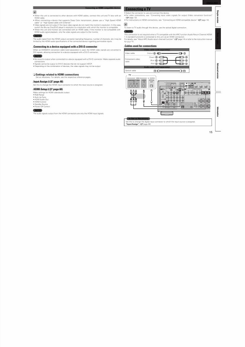
Connecting an HDMI-compatible device Connecting a TV• Select the connector to use and connect the device.
• For video connections, see “Converting input video s ignals or output (Video conversion uncti on)”
(vpage 13).
• For instructions on HDMI connections, see “Connecting an HDMI-compatible device” (vpage 14).
To listen to TV audio through this device, use the optical digital connection.
NOTE
This connection is not required when a TV compatible with the ARC unction (Audio Return Channel (HDMI1.4 standard unction)) is connected to this unit via an HDMI connection.
For details, see “About ARC (Audio return channel) unction” (vpage 14) or reer to the instruction manual
or your TV.
Cables used for connections
Video cable (sold separately)
Video cable (Yellow)
Component video
cable
(Green)
(Blue)
(Red)
Audio cable (sold separately)
Optical cable
IN
VIDEO
VIDEO
AUDIO
OPTICAL
OUT
COMPONENT VIDEO
Y PB PR
IN
TV
Set this to change the digital input connector to which the input source is assigned.
“Input Assign” (vpage 48)
in Set as Necessary
ENGLISH
8/7/2019 IBJSC.com | I-WEB.com.vn - 953467670
http://slidepdf.com/reader/full/ibjsccom-i-webcomvn-953467670 20/92
16
ENGLISH
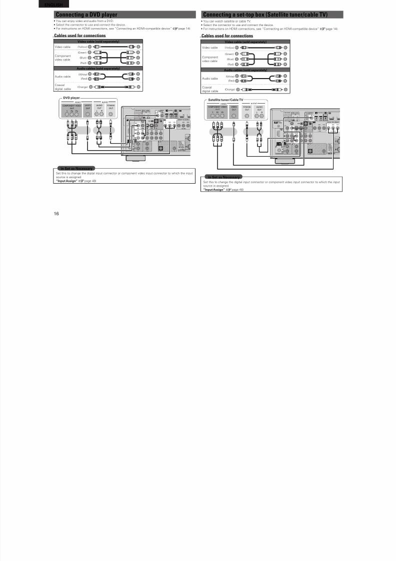
Connecting a DVD player• You can enjoy video and audio rom a DVD.
• Select the connector to use and connect the device.
• For instructions on HDMI connections, see “Connecting an HDMI-compatible device” (vpage 14).
Cables used for connectionsVideo cable (sold separately)
Video cable (Yellow)
Componentvideo cable
(Green)
(Blue)
(Red)
Audio cables (sold separately)
Audio cable(White)
(Red) R
L
R
L
Coaxial
digital cable(Orange)
RL
RL
VIDEO AUDIO
AUDIO
RL
OUTOUT
VIDEOCOMPONENT VIDEO
Y PB PR
OUT OUT
COAXIAL
DVD player
Set this to change the digital input connector or component video input connector to which the input
source is assigned.
“Input Assign” (vpage 48)
in Set as Necessary
Connecting a set-top box (Satellite tuner/cable TV)• You can watch satellite or cable TV.
• Select the connector to use and connect the device.
• For instructions on HDMI connections, see “Connecting an HDMI-compatible device” (vpage 14).
Cables used for connections
Video cable (sold separately)
Video cable (Yellow)
Componentvideo cable
(Green)
(Blue)
(Red)
Audio cables (sold separately)
Audio cable(White)
(Red) R
L
R
L
Coaxial
digital cable(Orange)
RL
RL
VIDEO AUDIO
AUDIO
RL
OUTOUT
VIDEOCOMPONENT VIDEO
Y PB PR
OUT OUT
COAXIAL
Satellite tuner/Cable TV
Set this to change the digital input connector or component video input connector to which the input
source is assigned.
“Input Assign” (vpage 48)
in Set as Necessary
ENGLISH
8/7/2019 IBJSC.com | I-WEB.com.vn - 953467670
http://slidepdf.com/reader/full/ibjsccom-i-webcomvn-953467670 21/92
17
ENGLISH
A d v a n c e d v e r s i o n
S i m p l e v e r s i o n
I n f o r m a t i o n
B a s i c v e r s i o n
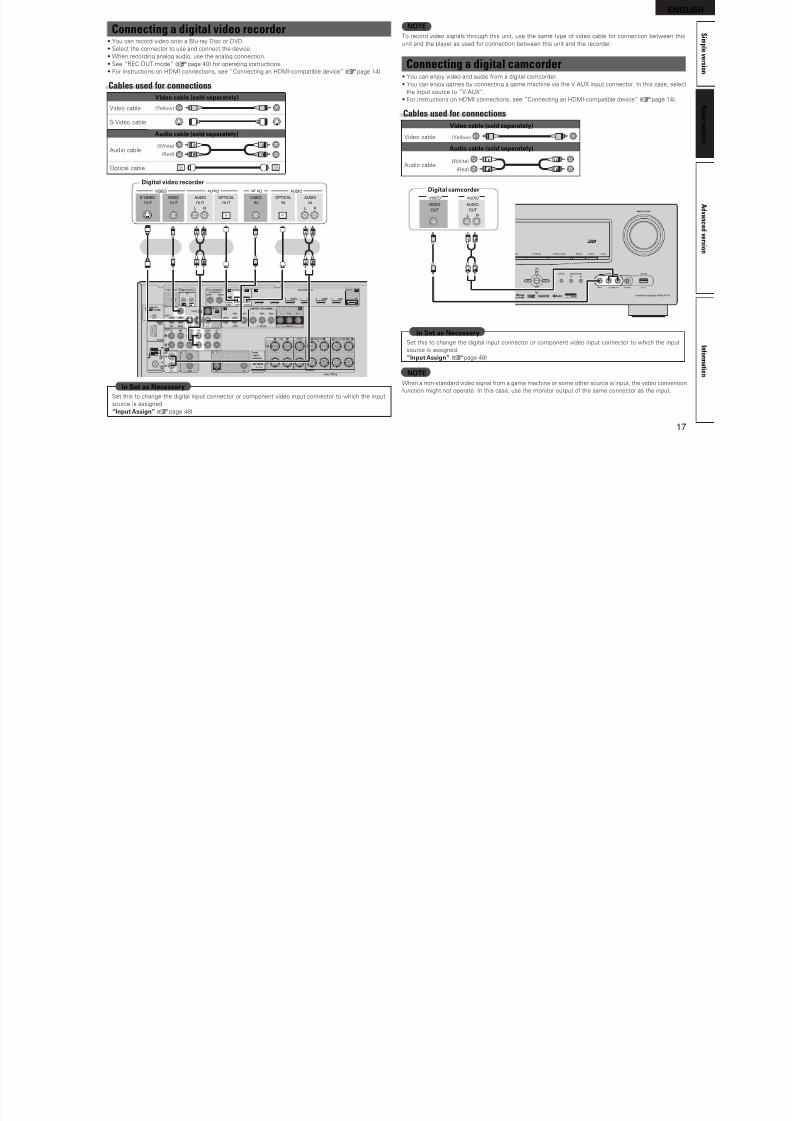
Connecting a digital video recorder• You can record video onto a Blu-ray Disc or DVD.
• Select the connector to use and connect the device.
• When recording analog audio, use the analog connection.
• See “REC OUT mode” (vpage 40) or operating instructions.
• For instructions on HDMI connections, see “Connecting an HDMI-compatible device” (vpage 14).
Cables used for connectionsVideo cable (sold separately)
Video cable (Yellow)
S-Video cable
Audio cable (sold separately)
Audio cable(White)
(Red) R
L
R
L
Optical cable
RL
RL
RL
RL
RL RL
OUT IN
AUDIOAUDIO VIDEOVIDEO
OUT IN
OPTICALOPTICAL
IN
AUDIOAUDIO
OUT
VIDEO
OUT
S-VIDEO VIDEO
Digital video recorder
Set this to change the digital input connector or component video input connector to which the input
source is assigned.
“Input Assign” (vpage 48)
in Set as Necessary
NOTETo record video signals through this unit, use the same type o video cable or connection between this
unit and the player as used or connection between this unit and the recorder.
Connecting a digital camcorder• You can enjoy video and audio rom a digital comcorder.
• You can enjoy games by connecting a game machine via the V.AUX input connector. In this case, select
the input source to “V.AUX”.
• For instructions on HDMI connections, see “Connecting an HDMI-compatible device” (vpage 14).
Cables used for connectionsVideo cable (sold separately)
Video cable (Yellow)
Audio cable (sold separately)
Audio cable(White)
(Red) R
L
R
L
RL
RL
OUT
AUDIOVIDEO
VIDEO AUDIO
RL
OUT
Digital camcorder
Set this to change the digital input connector or component video input connector to which the input
source is assigned.
“Input Assign” (vpage 48)
in Set as Necessary
NOTEWhen a non-standard video signal rom a game machine or some other source is input, the video conversion
unction might not operate. In this case, use the monitor output o the same connector as the input.
ENGLISH
8/7/2019 IBJSC.com | I-WEB.com.vn - 953467670
http://slidepdf.com/reader/full/ibjsccom-i-webcomvn-953467670 22/92
18
ENGLISH
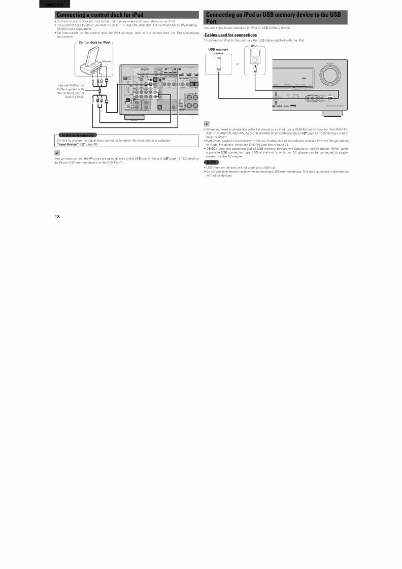
Connecting a control dock for iPod• Connect a control dock or iPod to the unit to enjoy video and music stored on an iPod.
• For a control dock or iPod, use ASD-1R, ASD-11R, ASD-3N, ASD-3W, ASD-51N and ASD-51W made by
DENON (sold separately).
• For instructions on the control dock or iPod settings, reer to the control dock or iPod’s operating
instructions.
R L
R L
ASD-51N
Control dock or iPod
Use the AV/Control
Cable supplied with
the DENON control
dock or iPod.
Set this to change the digital input connector to which the input source is assigned.
“Input Assign” (vpage 48)
in Set as Necessary
You can also connect the iPod you are using directly to the USB port o this unit (vpage 18 “Connecting
an iPod or USB memory device to the USB Port”).
Connecting an iPod or USB memory device to the USBPort
You can enjoy music stored on an iPod or USB memory device.
Cables used for connectionsTo connect an iPod to this unit, use the USB cable supplied with the iPod.
USB memorydevice
iPod
or
• When you want to playback a video fle stored on an iPod, use a DENON control dock or iPod (ASD-1R,
ASD-11R, ASD-3N, ASD-3W, ASD-51N and ASD-51W, sold separatel y) (vpage 18 “Connecting a control
dock or iPod”).
• With iPods, playback is possible with iPhone, iPod touch, classic and nano released rom the 5th-generation
o iPods. For details, check the DENON web site or page 24.
• DENON does not guarantee that all USB memory devices will operate or receive power. When using
a portable USB connection type HDD o the kind to which an AC adapter can be connected to supply
power, use the AC adapter.
NOTE• USB memory devices will not work via a USB hub.
• Do not use an extension cable when connecting a USB memory device. This may cause radi o intererencewith other devices.
ENGLISH
8/7/2019 IBJSC.com | I-WEB.com.vn - 953467670
http://slidepdf.com/reader/full/ibjsccom-i-webcomvn-953467670 23/92
19
ENGLISH
A d v a n c e d v e r s i o n
S i m p l e v e r s i o n
I n f o r m a t i o n
B a s i c v e r s i o n
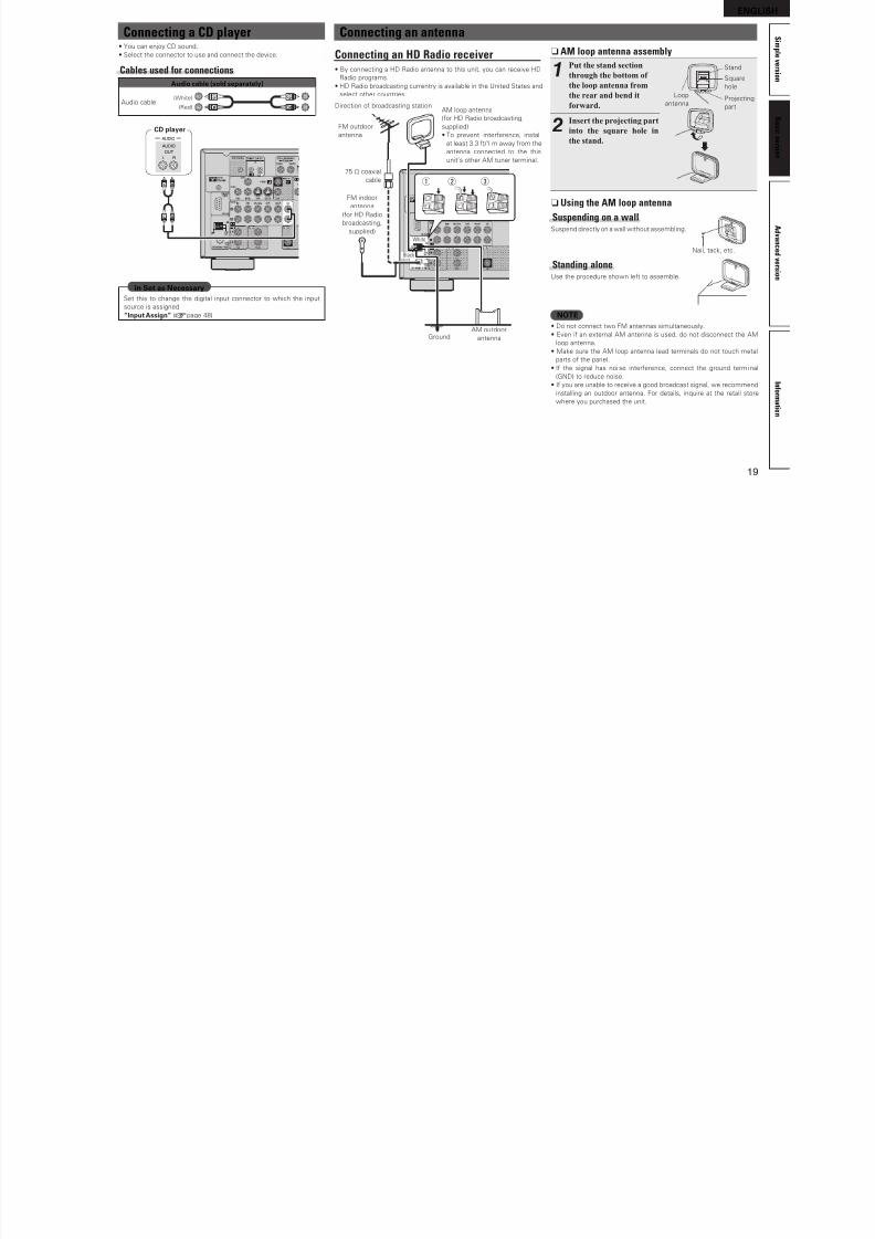
Connecting a CD player• You can enjoy CD sound.
• Select the connector to use and connect the device.
Cables used for connections
Audio cable (sold separately)
Audio cable(White)
(Red) R
L
R
L
RL
RL
AUDIO
AUDIO
RL
OUT
CD player
Set this to change the digital input connector to which the input
source is assigned.
“Input Assign” (vpage 48)
in Set as Necessary
Connecting an antenna
Connecting an HD Radio receiver• By connecting a HD Radio antenna to this unit, you can receive HD
Radio programs.
• HD Radio broadcasting currentry is available in the United States and
select other countries.
w eq
FM outdoorantenna
Direction o broadcasting station
75 Ω coaxial
cable
GroundAM outdoor
antenna
AM loop antenna
(or HD Radio broadcasting,
supplied)• To prevent intererence, install
at least 3.3 t/1 m away rom the
antenna connected to the this
unit’s other AM tuner terminal.
Black
White
FM indoor
antenna
(or HD Radio
broadcasting,
supplied)
n AM loop antenna assembly
1Put the stand section
through the bottom of
the loop antenna from
the rear and bend it
forward.
Stand
Square
hole
Projecting
part
Loop
antenna
2Insert the projecting part
into the square hole in
the stand.
n Using the AM loop antenna
Suspending on a wallSuspend directly on a wall without assembling.
Nail, tack, etc.
Standing aloneUse the procedure shown let to assemble.
NOTE• Do not connect two FM antennas simultaneously.
• Even i an external AM antenna is used, do not disconnect the AM
loop antenna.
• Make sure the AM loop antenna lead terminals do not touch metal
parts o the panel.
• I the signal has noi se intererence, connect the ground termi nal
(GND) to reduce noise.• I you are unable to receive a good broadcast signal, we recommend
installing an outdoor antenna. For details, inquire at the retail store
where you purchased the unit.
ENGLISH
8/7/2019 IBJSC.com | I-WEB.com.vn - 953467670
http://slidepdf.com/reader/full/ibjsccom-i-webcomvn-953467670 24/92
20
ENGLISH
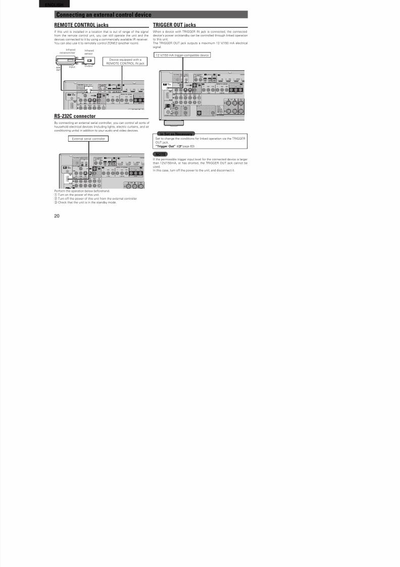
Connecting an external control device
REMOTE CONTROL jacksI this unit is installed in a location that is out o range o the signal
rom the remote control unit, you can still operate the unit and the
devices connected to it by using a commercially available IR receiver.
You can also use it to remotely control ZONE2 (another room).
AUX
OUT
Inraredretransmitter
Inraredsensor
OutputInput
Device equipped with a
REMOTE CONTROL IN jack
RS-232C connectorBy connecting an external serial controller, you can control all sorts o
household electrical devices (including lights, electric curtains, and air
conditioning units) in addition to your audio and video devices.
External serial controller
Perorm the operation below beorehand.
q Turn on the power o this unit.
w Turn o the power o this unit rom the external controller.
e Check that the unit is in the standby mode.
TRIGGER OUT jacksWhen a device with TRIGGER IN jack is connected, the connected
device’s power on/standby can be controlled through linked operation
to this unit.
The TRIGGER OUT jack outputs a maximum 12 V/150 mA electrical
signal.
12 V/150 mA trigger-compatible device
Set to change the conditions or linked operation via the TRIGGER
OUT jack.
“Trigger Out” (vpage 63)
in Set as Necessary
NOTEI the permissible trigger input level or the connected device is larger
than 12V/150mA, or has shorted, the TRIGGER OUT jack cannot be
used.
In this case, turn o the power to the unit, and disconnect it.
ENGLISH
8/7/2019 IBJSC.com | I-WEB.com.vn - 953467670
http://slidepdf.com/reader/full/ibjsccom-i-webcomvn-953467670 25/92
21
ENGLISH
A d v a n c e d v e r s i o n
S i m p l e v e r s i o n
I n f o r m a t i o n
B a s i c v e r s i o n
Playback (Basic operation)
n Playing a Blu-ray Disc player/DVD player
(vpage 22) n Playing a CD player (vpage 22)
n Playing an iPod® (vpage 22)
n Tuning in radio stations (vpage 25)
n Playing a USB memory device (vpage 27)
Selecting a listening mode (Surround mode)(vpage 28)
n Selecting the input source (vpage 21)
n Adjusting the master volume (vpage 21)
n Turning off the sound temporarily (vpage 21)
Playback (Advanced operation) (vpage 38)
Important informationBeore starting playback, make the connections between the dierent
components and the settings on the receiver.
NOTEAlso reer to the operating instructions o the connected components
when playing them.
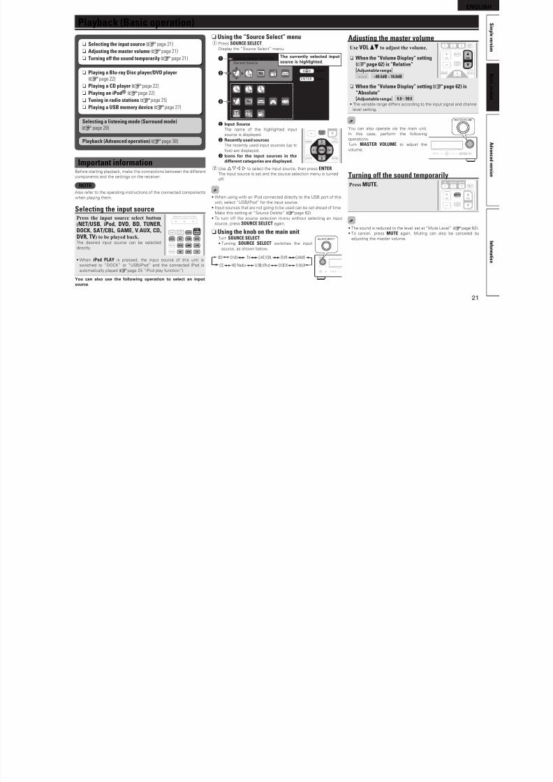
Selecting the input sourcePress the input source select button
(NET/USB, iPod, DVD, BD, TUNER,
DOCK, SAT/CBL, GAME, V.AUX, CD,
DVR, TV) to be played back.The desired input source can be selected
directly.
• When iPod PLAY is pressed, the input source o this unit is
switched to “DOCK” or “USB/iPod” and the connected iPod is
automatically played (vpage 25 “iPod play unction”).
You can also use the ollowing operation to select an inputsource.
n Using the “Source Select” menuq Press SOURCE SELECT.
Display the “Source Select” menu.
Source Select :SAT/CBL
Recent Source
Enter
Select
ENTER
The currently selected inputsource is highlighted.
q
w
e
q Input SourceThe name o the highlighted input
source is displayed.
w Recently used sourcesThe recently used input sources (up to
fve) are displayed.
e Icons or the input sources in thedierent categories are displayed.
w Use uio p to select the input source, then press ENTER.
The input source is set and the source selection menu is turned
o.
• When using with an iPod connected directly to the USB port o this
unit, select “USB/iPod” or the input source.
• Input sources that are not going to be used can be set ahead o time.
Make this setting at “Source Delete” (vpage 62).
• To turn o the source selection menu without selecting an input
source, press SOURCE SELECT again.
n Using the knob on the main unitTurn SOURCE SELECT.
• Turning SOURCE SELECT switches the input
source, as shown below.
BD D VD TV SAT/CBL GAMEDVR
V.AUXUSB/iPod DOCKHD RadioCD
Adjusting the master volumeUse VOL df to adjust the volume.
n When the “Volume Display” setting(vpage 62) is “Relative”GAdjustable rangeH
– – – –80.5dB – 18.0dB
n When the “Volume Display” setting (vpage 62) is“Absolute”GAdjustable rangeH 0.0 – 99.0
• The variable range diers according to the input signal and channel
level setting.
You can also operate via the main unit.
In this case, perorm the ollowing
operations.
Turn MASTER VOLUME to adjust the
volume.
Turning off the sound temporarilyPress MUTE.
• The sound is reduced to the level set at “Mute Level” (vpage 62).
• To cancel, press MUTE again. Muting can also be canceled by
adjusting the master volume.
ENGLISH
8/7/2019 IBJSC.com | I-WEB.com.vn - 953467670
http://slidepdf.com/reader/full/ibjsccom-i-webcomvn-953467670 26/92
22
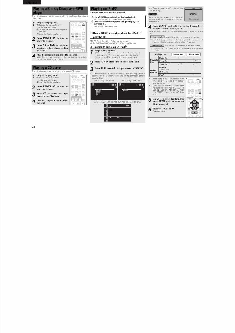
Playing a Blu-ray Disc player/DVDplayer
The ollowing describes the procedure or playing Blu-ray Disc player/
DVD player.
1Prepare for playback.q Turn on the power o the TV,
subwooer and player.
w Change the TV input to the input o
this unit.
e Load the disc in the player.
2Press POWER ON to turn on
power to the unit.
3Press BD or DVD to switch an
input source for a player used for
playback.
4Play the component connected to this unit.Make the necessary settings on the player (language setting,
subtitles setting, etc.) beorehand.
Playing a CD playerThe ollowing describes the procedure or playing CD player.
1Prepare for playback.q Turn on the power o the
subwooer and player.
w Load the disc in the player.
2Press POWER ON to turn on
power to the unit.
3Press CD to switch the input
source to the CD player.
4Play the component connected tothis unit.
Playing an iPod®There are two methods or iPod playback.
q Use a DENON Control dock or iPod to play back.You can play back both video, photo and audio.
w Connect an iPod directly to the USB port to play back(vpage 24).You can play back audio only.
q Use a DENON control dock for iPod toplay backDENON Control dock or iPod usable on this unit
• ASD-1R/ASD-11R/ASD-3N/ASD-3W/ASD-51N/ASD-51W
n Listening to music on an iPod®
1Prepare for playback.q Connect the DENON control dock or iPod to this unit
(vpage 18 “Connecting a control dock or iPod”).
w Set the iPod® in the DENON control dock or iPod.
2Press POWER ON to turn on power to the unit.
3Press DOCK to switch the input source to “DOCK”.
• I “Browse mode” is selected in step 4, the ollowing screen is
displayed on a TV screen, depending on the connected control
dock or iPod.
(When using an ASD-1R) (When using an ASD-11R)
iPod
Music
Video
U p/ Do wn S el ec t
(When using an ASD-3N, ASD-3W, ASD-51N and ASD-51W)
• In “Browse mode”, the iPod display is as
shown at right.
NOTEI the connections screen is not displayed,
the iPod may not be properly connected.
Reconnect it.
OK to disconnect.
4Press SEARCH and hold it down for 2 seconds or
more to select the display mode.
• There are two modes or displaying the contents recorded on the
iPod.Browse mode Display iPod inormation on the TV screen.
• English letters, numbers and cer tain symbols are displayed.
Incompatible characters are displayed as “.” (period).
Remote mode Display iPod inormation on the iPod screen.
• “Remote iPod” or “Dock Remote” is displayed on the display
o this unit.
Display mode Br owse mode Remote mode
Playablefles
Music fle P P
Photo fle P z2
Video fle Pz1 P z2
Activebuttons
Remotecontrol unit(This unit)
P P
iPod® P
z1 When using an ASD-11R, ASD-3N, ASD-
3W, ASD-51N or ASD-51W DENON
control dock or iPod.
z2 Video may not be output, depending on
the combination o ASD-1R, ASD-11R,
ASD-3N, ASD-3W, ASD-51N or ASD-
51W DENON control dock or iPod and
iPod.
5
Use ui to select the item, then
press ENTER or p to select the
le to be played.
6Press ENTER, p or 1.Playback starts.
ENGLISH
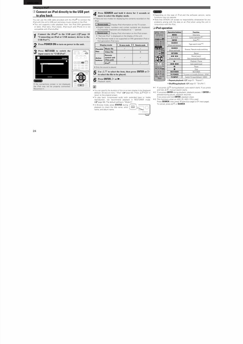
8/7/2019 IBJSC.com | I-WEB.com.vn - 953467670
http://slidepdf.com/reader/full/ibjsccom-i-webcomvn-953467670 27/92
23
A d v a n c
e d v e r s i o n
S i m p l e v e r s i o n
I n f o r m a t i o n
B a s i c v e r s i o n
Playing an iPod®
• You can speciy the duration o the on-screen di splay to be displayed
(deault: 30 sec) at menu “iPod” (vpage 63). Press uio p to
return to the original screen.
• To play back compressed audio with extended bass or treble
reproduction, we recommend playback in RESTORER mode
(vpage 56). The deault setting is “Mode 3”.
• In Browse mode, press STATUS during
playback to check the title name, artist
name, and album name.
NOTE• Press POWER OFF and set this unit’s power
to the standby mode beore disconnecting
the iPod. Also switch the input source to
“DOCK” beore disconnecting the iPod.
• Depending on the type o i Pod and the sotware version, some
unctions may not operate.
• Note that DENON will accept no responsibility whatsoever or any
problems arising with the data on an iPod when using this unit in
conjunction with the iPod.
n iPod operationOperation buttons Function
MENU Amp menu
uio p Cursor operationz1
ENTER Enterz2
SEARCH
(Press and release)Page search modez3
SEARCH
(Press and hold)Browse / Remote mode switching
RETURN Return
6 7
(Press and hold)
Manual search
(fast-reverse/fast-forward)
1 Playback / Pause
8 9 Auto search (cue)
3 Pause
2 Stop
RESTORER RESTORER
MEMORY Store memoryz4
TV POWER TV power on/standby (Default : SONY)
TV INPUT Switch TV input (Default : SONY)
• Repeat playback (vpage 51 “Repeat”)
• Shuing playback (vpage 51 “Shue”)
z1 I you press ui during playback, auto search starts. I you press
and hold ui, manual search starts.
z2 I you press ENTER during playback, playback pauses. I ENTER is
pressed during pause, playback resumes.
I you press and hold ENTER, playback stops.
z3 This unctions when an ASD-1R, ASD-11R is used.
Press SEARCH, then press o (previous page) or p (next page).
To cancel, press ui or SEARCH.
z4 This unctions when an ASD-3N, ASD-3W, ASD-51N or ASD-51W
is used.
n Viewing videos on an iPod® in the Browse modeWhen an iPod equipped with a video unction is connected to a
DENON ASD-11R, ASD-3N, ASD-3W, ASD-51N and ASD-51W
control dock or iPod, image fles can be played i n the Browse mode.
1Use ui to select “Videos”, then
press ENTER or p.
2Use ui to select the search item
or folder, then press ENTER or p.
3Use ui to select the video le,
then press ENTER, p or 1.Playback starts.
n Viewing photos and videos on an iPod® in theRemote modeThis unit can play back on a TV screen photos and data stored on an
iPod equipped with a slide show or video unction.
1Press and hold SEARCH to set the
Remote mode.“Remote iPod” or “Dock Remote” is
displayed on the display o this unit.
2Watching the iPod’s screen,
use ui to select “Photos” or
“Videos”.
• Depending on the iPod model, it may be necessary to operate the
iPod unit directly.
3Press ENTER until the image you want to view is
displayed.
“TV Out” at the iPod’s “Slide show Settings” or “Video Settings”
must be set to “On” in order to display the iPod’s photo data or vi deos
on the monitor. For details, see the iPod’s operating instructions.
NOTEVideo may not be output, depending on the combination o ASD-1R,
ASD-11R, ASD-3N, ASD-3W, ASD-51N or ASD-51W and iPod.
ENGLISH
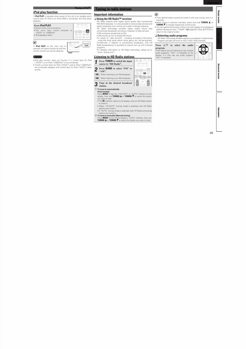
8/7/2019 IBJSC.com | I-WEB.com.vn - 953467670
http://slidepdf.com/reader/full/ibjsccom-i-webcomvn-953467670 28/92
24
Playing an iPod®
w Connect an iPod directly to the USB port to play back
You can use the USB cable provided with the iPod® to connect the
iPod with the unit’s USB port and enjoy music stored on the iPod.
• This unit supports audio playback rom the iPod (fth generation
or later), iPod nano, iPod classic, iPod touch and iPhone (it is not
compatible with iPod shue).
1Connect the iPod® to the USB port (vpage 18
“Connecting an iPod or USB memory device to the
USB Port”).
2Press POWER ON to turn on power to the unit.
3Press NET/USB to switch the
input source to “USB/iPod”.
[1/9]
Playlists
Artists
Albums
Songs
PodcastsGenres
Composers
Music
SEARCH Search
NOTEI the connections screen is not displayed,
the iPod may not be properly connected.
Reconnect it.
4Press SEARCH and hold it down for 2 seconds or
more to select the display mode.
• There are two modes or displaying the contents recorded on the
iPod.
Browse mode Display iPod inormation on the TV screen.
• English letters, numbers and certain symbols are displayed.
Incompatible characters are displayed as “.” (period).
Remote mode Display iPod inormation on the iPod screen.
• “Remote iPod” is displayed on the display o this unit.
• The Remote mode is not supported on fth generation iPod or
frst generation iPod nano.
Display mode Br owse mode Remote mode
Playablefles
Music fle P P
Video fle z
Activebuttons
Remotecontrol unit(This unit)
P P
iPod® P
zOnly the sound is played.
5Use ui to select the item, then press ENTER or p
to select the le to be played.
6Press ENTER, p or 1.Playback starts.
• You can speciy the duration o the on-sc reen display to be displayed
(deault: 30 sec) at menu “iPod” (vpage 63). Press uio p to
return to the original screen.
• To play back compressed audio with extended bass or treble
reproduction, we recommend playback in RESTORER mode
(vpage 56). The deault setting is “Mode 3”.
• In Browse mode, press STATUS during
playback to check the title name, artist
name, and album name.
NOTE• Depending on the type o iPod and the sotware vers ion, some
unctions may not operate.
• Note that DENON will accept no responsibility whatsoever or any
problems arising with the data on an iPod when using this unit in
conjunction with the iPod.
n iPod operation
Operation buttons Function
MENU Amp menuuio p Cursor operationz1
ENTER Enterz2
SEARCH
(Press and release)Page search modez3
SEARCH
(Press and hold)Browse / Remote mode switching
RETURN Return
6 7
(Press and hold)
Manual search
(fast-reverse/fast-forward)
1 Playback / Pause
8 9 Auto search (cue)
3 Pause
2 StopRESTORER RESTORER
TV POWER TV power on/standby (Default : SONY)
TV INPUT Switch TV input (Default : SONY)
• Repeat playback (vpage 51 “Repeat”)
• Shuing playback (vpage 51 “Shue”)
z1 I you press ui during playback, auto search starts. I you press
and hold ui, manual search starts.
z2 I you press ENTER during playback, playback pauses. I ENTER is
pressed during pause, playback resumes.
I you press and hold ENTER, playback stops.
z3 This unctions when an ASD-1R, ASD-11R is used.
Press SEARCH, then press o (previous page) or p (next page).
To cancel, press ui or SEARCH.
ENGLISH
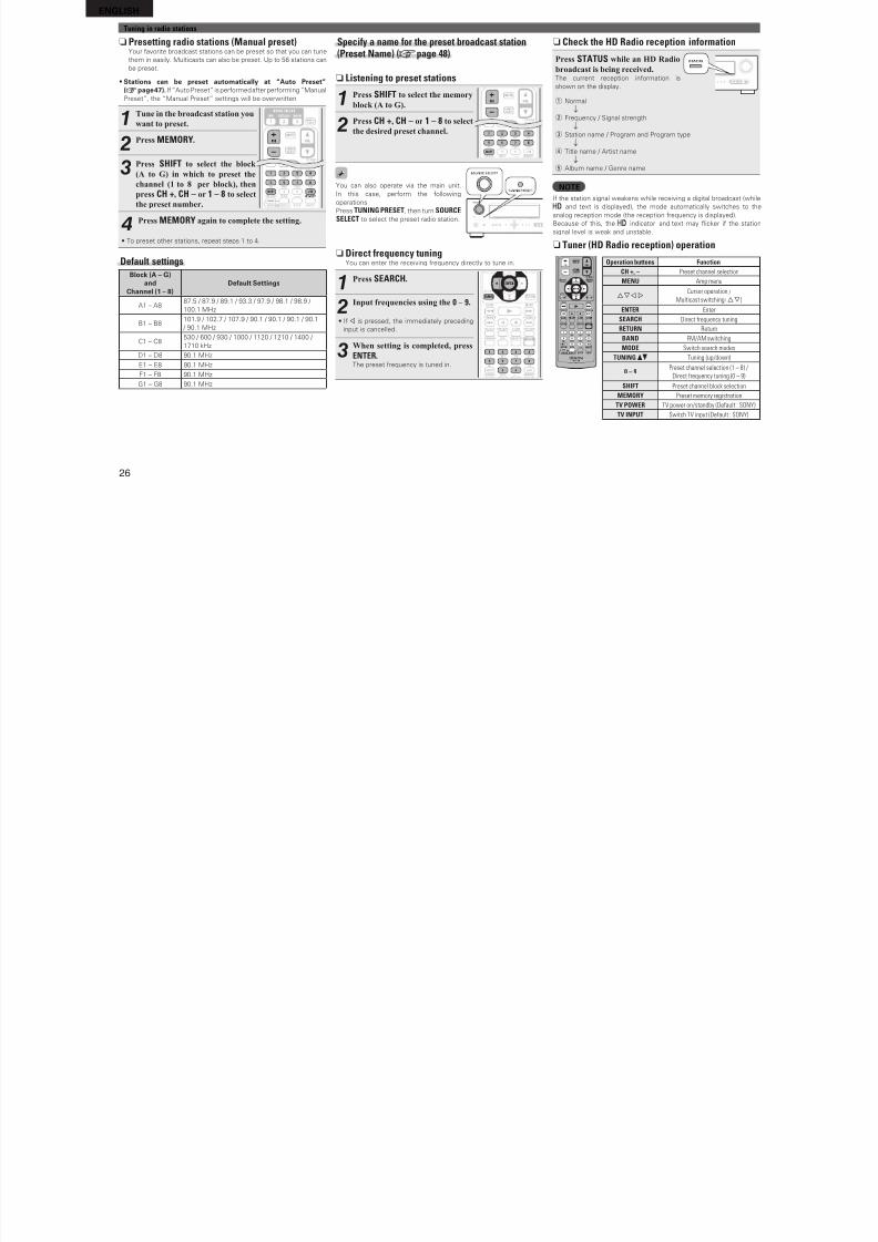
8/7/2019 IBJSC.com | I-WEB.com.vn - 953467670
http://slidepdf.com/reader/full/ibjsccom-i-webcomvn-953467670 29/92
25
A d v a n c
e d v e r s i o n
S i m p l e v e r s i o n
I n f o r m a t i o n
B a
s i c v e r s i o n
Playing an iPod®Tuning in radio stations
Important information
n Using the HD Radio™ receiverHD Radio stations oer higher sound quality than conventional
FM/ AM broadcasts. It is also possible to receive data services and
select broadcasts rom among up to eight multicast programs.
HD Radio technology provides higher quality sound than
conventional broadcasts and allows reception o data services.
• FM sounds as sensational as CDs
• AM sounds as rich as analog FM stereo• A variety o “data services”, i ncluding text-based inormation,
song title, artist name, album name, genre, etc. can be received.
Furthermore, in addition to conventional broadcasts, with HD
Radio broadcasting it is possible to choose rom up to 8 multicast
programs.
For detailed inormation on HD Radio technology, please go to
“www. ibiquity.com”.
Listening to HD Radio stations
1Press TUNER to switch the input
source to “HD Radio”.
2
Press BAND to select “FM” or
“AM”.
FM When listening to an FM broadcast.
AM When listening to an AM broadcast.
3Tune in the desired broadcast
station.
q To tune in automatically(Auto tuning)Press MODE to light the “HD-AUTO” or “AUTO” indicator on the
display, then use TUNING d or TUNING f to select the station
you want to hear.
• The indicator lights on the display when an HD Radio station
is tuned in.
• When “HD-AUTO” (tuning mode) is selected, only HD Radiostations are tuned in.
• I “AUTO” (tuning mode) is selected, both HD Radio and anal og
stations are tuned in.
w To tune in manually (Manual tuning)Press MODE to turn o the display’s “AUTO” indicator, then use
TUNING d or TUNING f to select the station you want to hear.
• I the desired station cannot be tuned in with auto tuning, tune it in
manually.
• When tuning in stat ions manually, press and hold TUNING d or
TUNING f to change requencies continuously.
• You can speciy the duration o the on-sc reen display to be displayed
(deault: 30 sec) at menu “TUNER” (vpage 63). Press uio p to
return to the original screen.
n Selecting audio programsHD Radio Technology enables stations to broadcast multiple Audio
Program and data services on HD2 / HD3 / HD4 channels.
Press ui to select the audio
program.I the station you are listening to has multiple
audio programs, “HD1” is indicated on the
display. I it only has one audio program,
“HD” is indicated.
iPod play functionI iPod PLAY is pressed when power o this unit is on standby and a
control dock or iPod or an iPod (USB) is connected, the iPod starts
playback.
Press iPod PLAY.• Power o this unit is turned on.
• This unit’s input source switches to
“DOCK” or “USB/iPod”.
• iPod playback starts.
I iPod PLAY on the main unit is
pressed, the same unction as with the
remote control unit can be obtained.
NOTE• iPod play unction does not unction i a control dock or iPod
(“DOCK”) or an iPod (“USB/iPod”) is not connected.
• I both a control dock or iPod (“DOCK”) and an iPod (“USB/iPod”)
are connected, playback with control dock or iPod (“DOCK”) takes
priority.
ENGLISH
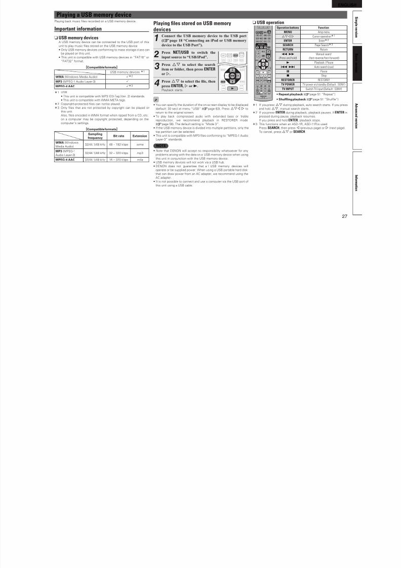
8/7/2019 IBJSC.com | I-WEB.com.vn - 953467670
http://slidepdf.com/reader/full/ibjsccom-i-webcomvn-953467670 30/92
26
Specify a name for the preset broadcast station(Preset Name) (vpage 48)
n Listening to preset stations
1Press SHIFT to select the memory
block (A to G).
2
Press CH +, CH – or 1 – 8 to select
the desired preset channel.
You can also operate via the main unit.
In this case, perorm the ollowing
operations.
Press TUNING PRESET, then turn SOURCESELECT to select the preset radio station.
n Direct frequency tuningYou can enter the receiving requency directly to tune in.
1Press SEARCH.
2Input frequencies using the 0 – 9.
• I o is pressed, the immediately preceding
input is cancelled.
3When setting is completed, press
ENTER.The preset requency is tuned in.
n Check the HD Radio reception information
Press STATUS while an HD Radio
broadcast is being received.The current reception inormation is
shown on the display.
q Normal
w Frequency / Signal strength
e Station name / Program and Program type
r Title name / Artist name
t Album name / Genre name
NOTEI the station signal weakens while receiving a digital broadcast (while
and text is displayed), the mode automatically switches to the
analog reception mode (the reception requency is displayed).
Because o this, the indicator and text may icker i the station
signal level is weak and unstable.
n Tuner (HD Radio reception) operation
Operation buttons Function
CH +, – Preset channel selection
MENU Amp menu
uio pCursor operation /
Multicast switching (ui)
ENTER Enter
SEARCH Direct frequency tuning
RETURN Return
BAND FM/AM switching
MODE Switch search modes
TUNINGdf Tuning (up/down)
0 – 9Preset channel selection (1 – 8) /
Direct frequency tuning (0 – 9)SHIFT Preset channel block selection
MEMORY Preset memory registration
TV POWER TV power on/standby (Default : SONY)
TV INPUT Switch TV input (Default : SONY)
Tuning in radio stations
n Presetting radio stations (Manual preset)Your avorite broadcast stations can be preset so that you can tune
them in easily. Multicasts can also be preset. Up to 56 stations can
be preset.
• Stations can be preset automatically at “Auto Preset”(vpage 47). I “Auto Preset” is perormed ater perorming “Manual
Preset”, the “Manual Preset” settings will be overwritten.
1Tune in the broadcast station you
want to preset.
2Press MEMORY.
3Press SHIFT to select the block
(A to G) in which to preset the
channel (1 to 8 per block), then
press CH +, CH – or 1 – 8 to select
the preset number.
4Press MEMORY again to complete the setting.
• To preset other stations, repeat steps 1 to 4.
Default settingsBlock (A – G)
andChannel (1 – 8)
Deault Settings
A1 – A887.5 / 87.9 / 89.1 / 93.3 / 97.9 / 98.1 / 98.9 /
100.1 MHz
B1 – B8101.9 / 102.7 / 107.9 / 90.1 / 90.1 / 90.1 / 90.1
/ 90.1 MHz
C1 – C8530 / 600 / 930 / 1000 / 1120 / 1210 / 1400 /
1710 kHz
D1 – D8 90.1 MHz
E1 – E8 90.1 MHz
F1 – F8 90.1 MHzG1 – G8 90.1 MHz
ENGLISH
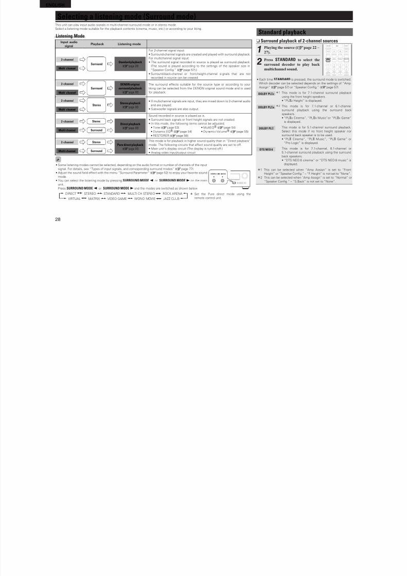
8/7/2019 IBJSC.com | I-WEB.com.vn - 953467670
http://slidepdf.com/reader/full/ibjsccom-i-webcomvn-953467670 31/92
27
A d v a n c
e d v e r s i o n
S i m p l e v e r s i o n
I n f o r m a t i o n
B a
s i c v e r s i o n
Playing les stored on USB memorydevices
1Connect the USB memory device to the USB port
(vpage 18 “Connecting an iPod or USB memory
device to the USB Port”).
2Press NET/USB to switch the
input source to “USB/iPod”.
3Press ui to select the search
item or folder, then press ENTER
or p.
4Press ui to select the le, then
press ENTER, p or 1.Playback starts.
• You can speciy the duration o the on-sc reen display to be displayed
(deault: 30 sec) at menu “USB” (vpage 63). Press uio p to
return to the original screen.
• To play back compressed audio with extended bass or treblereproduction, we recommend playback in RESTORER mode
(vpage 56). The deault setting is “Mode 3”.
• I the USB memory device is divided into multiple partitions, only the
top partition can be selected.
• This unit is compatible with MP3 fles conorming to “MPEG-1 Audio
Layer-3” standards.
NOTE• Note that DENON will accept no responsibility whatsoever or any
problems arising with the data on a USB memory device when using
this unit in conjunction with the USB memory device.
• USB memory devices will not work via a USB hub.
• DENON does not guarantee that al l USB memory devices will
operate or be supplied power. When using a USB portable hard disk
that can draw power rom an AC adapter, we recommend using the
AC adapter.
• It is not possible to connect and use a computer via the USB port o
this unit using a USB cable.
n USB operationOperation buttons Function
MENU Amp menu
uio p Cursor operationz1
ENTER Enterz2
SEARCH Page Searchz3
RETURN Return
6 7
(Press and hold)
Manual search
(fast-reverse/fast-forward)1 Playback / Pause
8 9 Auto search (cue)
3 Pause
2 Stop
RESTORER RESTORER
TV POWER TV power on/standby (Default : SONY)
TV INPUT Switch TV input (Default : SONY)
• Repeat playback (vpage 51 “Repeat”)
• Shuing playback (vpage 51 “Shue”)
z1 I you press ui during playback, auto search starts. I you press
and hold ui, manual search starts.
z2 I you press ENTER during playback, playback pauses. I ENTER is
pressed during pause, playback resumes.I you press and hold ENTER, playback stops.
z3 This unctions when an ASD-1R, ASD-11R is used.
Press SEARCH, then press o (previous page) or p (next page).
To cancel, press ui or SEARCH.
Playing a USB memory devicePlaying back music fles recorded on a USB memory device.
Important information
nUSB memory devicesA USB memory device can be connected to the USB port o this
unit to play music fles stored on the USB memory device.
• Only USB memory devices conorming to mass storage cl ass can
be played on this unit.
• This unit is compatible with USB memory devices in “FAT16” or“FAT32” ormat.
GCompatible ormatsH
USB memory devices z1
WMA (Windows Media Audio) Pz2
MP3 (MPEG-1 Audio Layer-3) P
MPEG-4 AAC Pz3
z1 USB
• This unit is compatible with MP3 ID3-Tag (Ver. 2) standards.
• This unit is compatible with WMA META tags.
z2 Copyright-protected fles can not be played.
z3 Only fles that are not protected by copyright can be played on
this unit.
Also, fles encoded in WMA ormat when ripped rom a CD, etc.on a computer may be copyright protected, depending on the
computer’s settings.
GCompatible ormatsH
Samplingrequency
Bit rate Extension
WMA (Windows
Media Audio)32/44.1/48 kHz 48 – 192 kbps .wma
MP3 (MPEG-1
Audio Layer-3)32/44.1/48 kHz 32 – 320 kbps .mp3
MPEG-4 AAC 32/44.1/48 kHz 16 – 320 kbps .m4a
ENGLISH
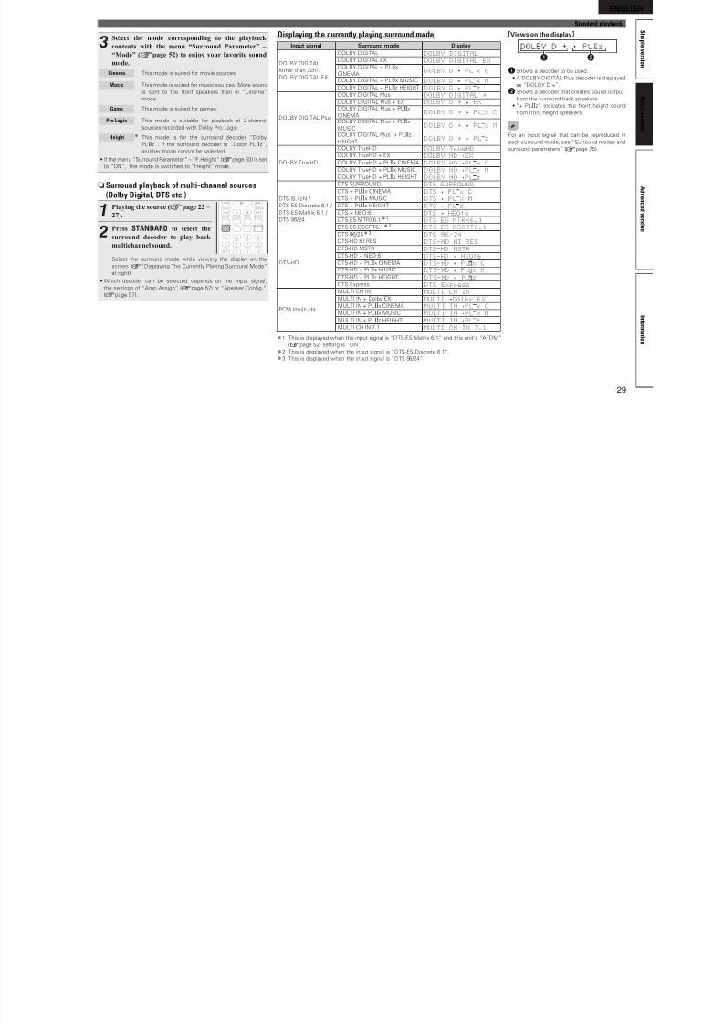
8/7/2019 IBJSC.com | I-WEB.com.vn - 953467670
http://slidepdf.com/reader/full/ibjsccom-i-webcomvn-953467670 32/92
28
Standard playback
n Surround playback of 2-channel sources
1Playing the source (vpage 22 –
27).
2Press STANDARD to select thesurround decoder to play back
multichannel sound.
• Each time STANDARD is pressed, the surround mode is switched.
Which decoder can be selected depends on the settings o “Amp
Assign” (vpage 57) or “Speaker Confg.” (vpage 57).
DOLBY PLgzz1 This mode is or 7.1-channel surround playback
using the ront height speakers.
• “PLgz Height” is displayed.
DOLBY PLgxz2 This mode is or 7.1-channel or 6.1-channel
surround playback using the surround back
speakers.
• “PLgx Cinema”, “PLgx Music”or “PLgx Game”is displayed.
DOLBY PLg This mode is or 5.1-channel surround playback.
Select this mode i no ront height speaker nor
surround back speaker is to be used.
• “PLg Cinema”, “PLg Music”, “PLg Game” or
“Pro Logic” is displayed.
DTS NEO:6 This mode is or 7.1-channel, 6.1-channel or
5.1-channel surround playback using the surround
back speakers.
• “DTS NEO:6 cinema” or “DTS NEO:6 music” is
displayed.
z1 This can be selected when “Amp Assign” is set to “Front
Height” or “Speaker Confg.” – “F.Height” is not set to “None”.z2 This can be selected when “Amp Assign” is set to “Normal” or
“Speaker Confg.” – “S.Back” is not set to “None”.
Selecting a listening mode (Surround mode)This unit can play input audio signals in multi-channel surround mode or in stereo mode.
Select a listening mode suitable or the playback contents (cinema, music, etc.) or according to your liking.
Listening ModeInput audio
signalPlayback Listening mode
2-channel
Multi channel
SurroundStandard playback
(vpage 28)
For 2-channel signal input:
• Surround-channel signals are created and played with surround playback.
For multichannel signal input:• The surround signal recorded in source is played as surround playback.
(The sound is played according to the settings o the speaker size in
“Speaker Confg.” (vpage 57).)
• Surround-back-channel or ront-height-channel si gnals that are not
recorded in source can be created.
2-channel
Multi channel
Surround
DENON original
surround playback
(vpage 30)
The surround eects suitable or the source type or according to your
liking can be selected rom the DENON original sound mode and is used
or playback.
2-channel
Multi channel
StereoStereo playback
(vpage 30)
• I multichannel signals are input, they are mixed down to 2-channel audio
and are played.
• Subwooer signals are also output.
2-channel
Multi channel
Stereo
Surround
Direct playback
(vpage 30)
Sound recorded in source is played as is.• Surround back signals or ront height signals are not created.
• In this mode, the ollowing items cannot be adjusted.
• Tone (vpage 53) • MultEQ® (vpage 54)
• Dynamic EQ® (vpage 54) • Dynami c Vol ume® (vpage 55)
• RESTORER (vpage 56)
2-channel
Multi channel
Stereo
Surround
Pure direct playback
(vpage 30)
This mode is or playback in higher sound quality than in “Direct playback”
mode. The ollowing circuits that aect sound quality are set to o.
• Main unit’s display circuit (The display is turned o.)
• Analog video input/output circuit
• Some listening modes cannot be selected, depending on the audio ormat or number o channels o the input
signal. For details, see “Types o input signals, and corresponding surround modes” (vpage 77).
• Adjust the sound feld eect with the menu “Surround Parameter” (vpage 52) to enjoy your avorite sound
mode.
• You can select the listening mode by pressing SURROUND MODE 0 or SURROUND MODE 1 on the main
unit.
Press SURROUND MODE 0 or SURROUND MODE 1 and the modes are switched as shown below.
z Set the Pure direct mode using the
remote control unit.
DIRECT STEREO STANDARD MULTI CH STEREO ROCK ARENA
MONO MOVIE JAZZ CLUBVIDEO GAMEMATRIXVIRTUAL
ENGLISH
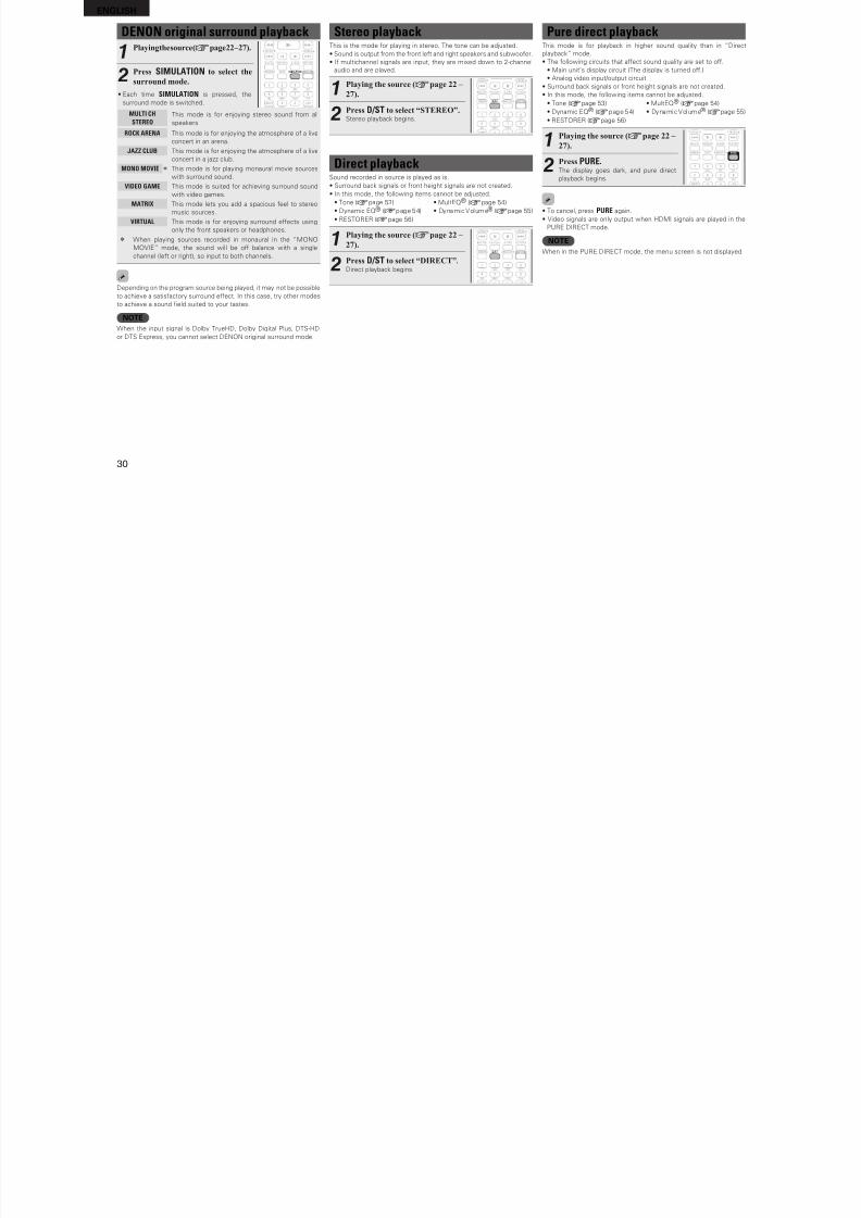
8/7/2019 IBJSC.com | I-WEB.com.vn - 953467670
http://slidepdf.com/reader/full/ibjsccom-i-webcomvn-953467670 33/92
29
A d v a n c
e d v e r s i o n
S i m p l e v e r s i o n
I n f o r m a t i o n
B a
s i c v e r s i o n
3Select the mode corresponding to the playback
contents with the menu “Surround Parameter” –
“Mode” (vpage 52) to enjoy your favorite sound
mode.
Cinema This mode is suited or movie sources.
Music This mode is suited or music sources. More sound
is sent to the ront speakers than in “Cinema”
mode.
Game This mode is suited or games.
Pro Logic This mode is suitable or playback o 2-channel
sources recorded with Dolby Pro Logic.
Height z This mode is or the surround decoder “Dolby
PLgz”. I the surround decoder is “Dolby PLgz”,
another mode cannot be selected.
• I the menu “Surround Parameter” – “F.Height” (vpage 53) is set
to “ON”, the mode is switched to “Height” mode.
n Surround playback of multi-channel sources(Dolby Digital, DTS etc.)
1Playing the source (vpage 22
–
27).
2Press STANDARD to select the
surround decoder to play back
multichannel sound.
Select the surround mode while viewing the display on the
screen (v“Displaying The Currently Playing Surround Mode”
at right).
• Which decoder can be selected depends on the input signal,
the settings o “Amp Assign” (vpage 57) or “Speaker Confg.”
(vpage 57).
Displaying the currently playing surround modeInput signal Surround mode Display
DOLBY DIGITAL
(other than 2ch) /
DOLBY DIGITAL EX
DOLBY DIGITAL DOLBY DIGITAL
DOLBY DIGITAL EX DOLBY DIGITAL EX
DOLBY DIGITAL + PLgx
CINEMADOLBY D PL x C
DOLBY DIGITAL + PLgx MUSIC DOLBY D PL x M
DOLBY DIGITAL + PLgz HEIGHT DOLBY D PL z
DOLBY DIGITAL Plus
DOLBY DIGITAL Plus DOLBY DIGITAL +
DOLBY DIGITAL Plus + EX DOLBY D + EX
DOLBY DIGITAL Plus + PLgx
CINEMADOLBY D + PL x C
DOLBY DIGITAL Plus + PLgx
MUSICDOLBY D + PL x M
DOLBY DIGITAL Plus + PLgz
HEIGHTDOLBY D + PL z
DOLBY TrueHD
DOLBY TrueHD DOLBY TrueHD
DOLBY TrueHD + EX DOLBY HD EX
DOLBY TrueHD + PLgx CINEMA DOLBY HD PL x C
DOLBY TrueHD + PLgx MUSIC DOLBY HD PL x M
DOLBY TrueHD + PLgz HEIGHT DOLBY HD PL z
DTS (5.1ch) /
DTS-ES Discrete 6.1 /
DTS-ES Matrix 6.1 /
DTS 96/24
DTS SURROUND DTS SURROUND
DTS + PLgx CINEMA DTS PL x C
DTS + PLgx MUSIC DTS PL x M
DTS + PLgz HEIGHT DTS PL z
DTS + NEO:6 DTS NEO:6
DTS ES MTRX6.1z1 DTS ES MTRX6.1
DTS ES DSCRT6.1z2 DTS ES DSCRT6.1
DTS 96/24z3 DTS 96/24
DTS-HD
DTS-HD HI RES DTS-HD HI RES
DTS-HD MSTR DTS-HD MSTR
DTS-HD + NEO:6 DTS-HD NEO:6
DTS-HD + PLgx CINEMA DTS-HD PL x C
DTS-HD + PLgx MUSIC DTS-HD PL x M
DTS-HD + PLgz HEIGHT DTS-HD PL z
DTS Express DTS Express
PCM (multi ch)
MULTI CH IN MULTI CH IN
MULTI IN + Dolby EX MULTI Dolby EX
MULTI IN + PLgx CINEMA MULTI IN PL x C
MULTI IN + PLgx MUSIC MULTI IN PL x M
MULTI IN + PLgz HEIGHT MULTI IN PL z
MULTI CH IN 7.1 MULTI CH IN 7.1
z1 This is displayed when the input signal is “DTS-ES Matrix 6.1” and this unit’s “AFDM”
(vpage 52) setting is “ON”.
z2 This is displayed when the input signal is “DTS-ES Discrete 6.1”.
z3 This is displayed when the input signal is “DTS 96/24”.
Standard playback
GViews on the displayH
q w
qShows a decoder to be used.
• A DOLBY DIGITAL Plus decoder is displayed
as “DOLBY D +”.
wShows a decoder that creates sound output
rom the surround back speakers.
• “+ PLgz” indicates the ront height soundrom ront height speakers.
For an input signal that can be reproduced in
each surround mode, see “Surround modes and
surround parameters” (vpage 75).
ENGLISH
8/7/2019 IBJSC.com | I-WEB.com.vn - 953467670
http://slidepdf.com/reader/full/ibjsccom-i-webcomvn-953467670 34/92
30
DENON original surround playback
1Playing the source (vpage 22–27).
2Press SIMULATION to select the
surround mode.
• Each time SIMULATION is pressed, the
surround mode is switched.
MULTI CH
STEREOThis mode is or enjoying stereo sound rom all
speakers.
ROCK ARENA This mode is or enjoying the atmosphere o a live
concert in an arena.
JAZZ CLUB This mode is or enjoying the atmosphere o a live
concert in a jazz club.
MONO MOVIE z This mode is or playing monaural movie sources
with surround sound.
VIDEO GAME This mode is suited or achieving surround sound
with video games.
MATRIX This mode lets you add a spacious eel to stereo
music sources.
VIRTUAL This mode is or enjoying surround eects using
only the ront speakers or headphones.
z When playing sources recorded in monaural in the “MONO
MOVIE” mode, the sound will be o balance with a singlechannel (let or right), so input to both channels.
Depending on the program source being played, it may not be possible
to achieve a satisactory surround eect. In this case, try other modes
to achieve a sound feld suited to your tastes.
NOTEWhen the input signal is Dolby TrueHD, Dolby Digital Plus, DTS-HD
or DTS Express, you cannot select DENON original surround mode.
Stereo playbackThis is the mode or playing in stereo. The tone can be adjusted.
• Sound is output rom the ront let and right speakers and subwooer.
• I multichannel signals are input, they are mixed down to 2-channel
audio and are played.
1Playing the source (vpage 22 –
27).
2Press D/ST to select “STEREO”.Stereo playback begins.
Direct playbackSound recorded in source is played as is.
• Surround back signals or ront height signals are not created.
• In this mode, the ollowing items cannot be adjusted.
• Tone (vpage 53) • MultEQ® (vpage 54)
• Dynamic EQ® (vpage 54) • Dynamic Volume® (vpage 55)
• RESTORER (vpage 56)
1Playing the source (vpage 22 –
27).
2Press D/ST to select “DIRECT”.Direct playback begins.
Pure direct playbackThis mode is or playback in higher sound quality than in “Direct
playback” mode.
• The ollowing circuits that aect sound quality are set to o.
• Main unit’s display circuit (The display is turned o.)
• Analog video input/output circuit
• Surround back signals or ront height signals are not created.
• In this mode, the ollowing items cannot be adjusted.
• Tone (vpage 53) • MultEQ® (vpage 54)
• Dynamic EQ® (vpage 54) • Dynamic Volume® (vpage 55)
• RESTORER (vpage 56)
1Playing the source (vpage 22 –
27).
2Press PURE.The display goes dark, and pure direct
playback begins.
• To cancel, press PURE again.
• Video signals are only output when HDMI signals are played in the
PURE DIRECT mode.
NOTEWhen in the PURE DIRECT mode, the menu screen is not displayed.
ENGLISH
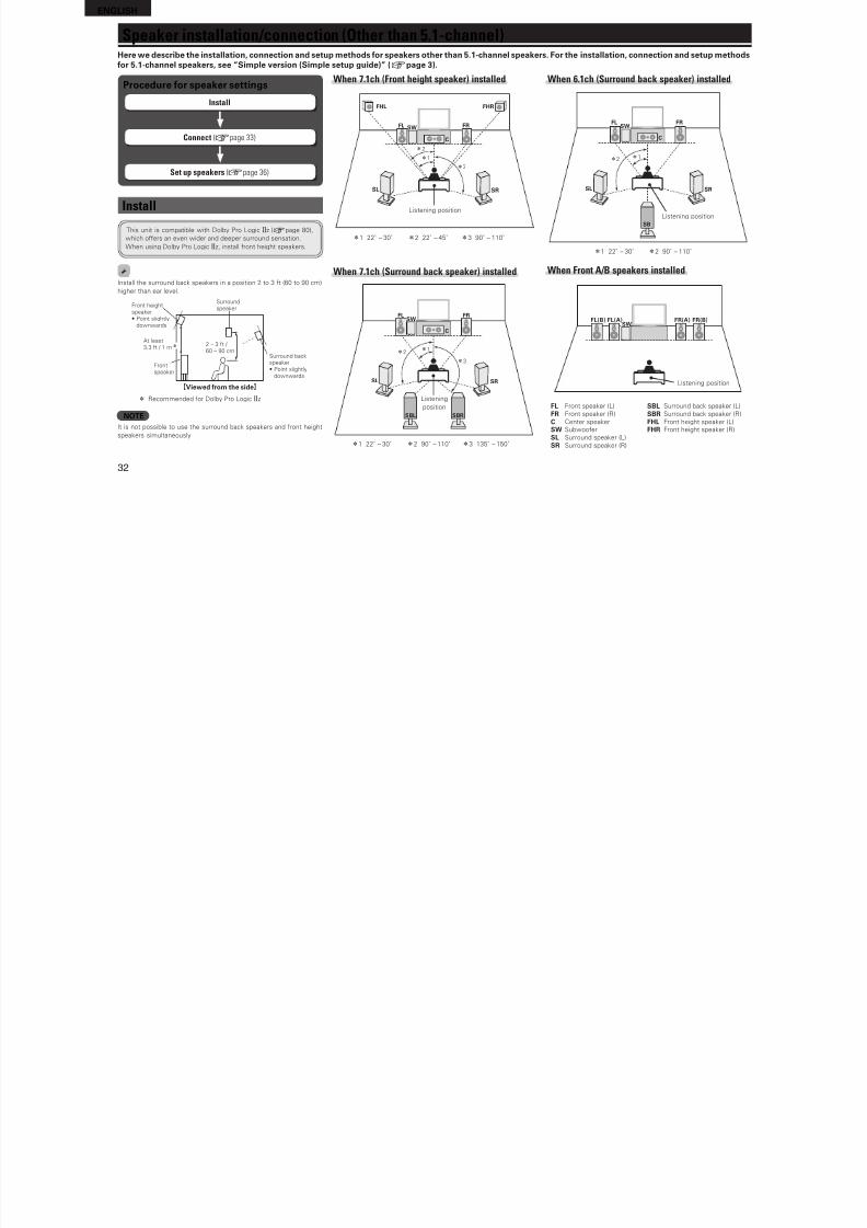
8/7/2019 IBJSC.com | I-WEB.com.vn - 953467670
http://slidepdf.com/reader/full/ibjsccom-i-webcomvn-953467670 35/92
Advancedversion
31
B a
s i c v e r s i o n
S i m p l e v e r s i o n
I n f o r m a t i o n
A d v a n c
e d v e r s i o n
F Speaker installation/connection (Other than 5.1-channel) vpage 32
F Playback (Advanced operation) vpage 38
F Playback in ZONE2 (Separate room) vpage 41
F How to make detailed settings vpage 43
F Operating the connected devices by remote control unit vpage 65
Advanced versionHere, we explain unctions and operations that let you make better use o this unit.
ENGLISH
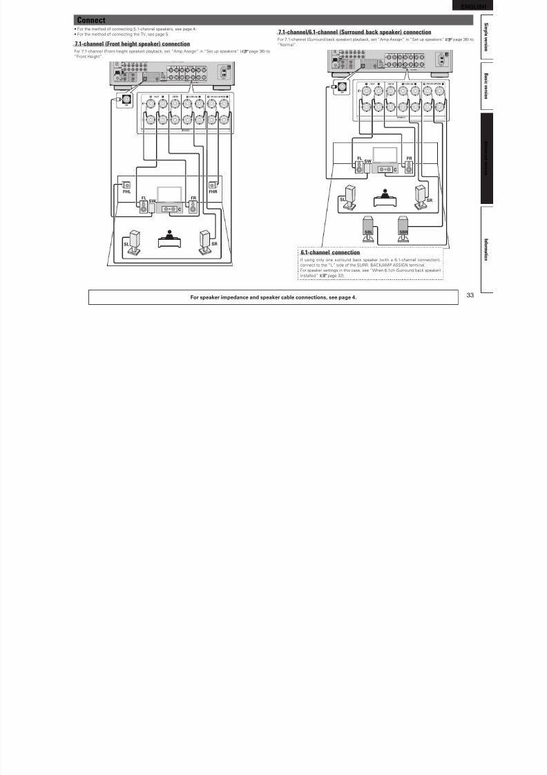
8/7/2019 IBJSC.com | I-WEB.com.vn - 953467670
http://slidepdf.com/reader/full/ibjsccom-i-webcomvn-953467670 36/92
32
When 6.1ch (Surround back speaker) installed
FL FR
C
SB
SL SR
SW
z1z2
Listening position
z1 22˚ – 30˚ z2 90˚ – 110˚
When Front A/B speakers installed
FR(A) FR(B)SW
FL(B) FL(A)
Listening position
FL Front speaker (L) SBL Surround back speaker (L)
FR Front speaker (R) SBR Surround back speaker (R)
C Center speaker FHL Front height speaker (L)
SW Subwooer FHR Front height speaker (R)
SL Surround speaker (L)
SR Surround speaker (R)
Procedure or speaker settings
Install
Connect (vpage 33)
Set up speakers (vpage 36)
Install
This unit is compatible with Dolby Pro Logic gz (vpage 80),
which oers an even wider and deeper surround sensation.
When using Dolby Pro Logic gz, install ront height speakers.
Install the surround back speakers in a position 2 to 3 t (60 to 90 cm)
higher than ear level.
z
Surroundspeaker
2 – 3 t / 60 – 90 cm
GViewed rom the sideH
Front heightspeaker• Point slightly
downwards
At least3.3 t / 1 m
Surround backspeaker• Point slightly
downwards
Front
speaker
z Recommended or Dolby Pro Logic gz
NOTEIt is not possible to use the surround back speakers and ront height
speakers simultaneously.
When 7.1ch (Front height speaker) installed
FL FR
FHRFHL
C
SL SR
SW
z1
z2
z3
Listening position
z1 22˚ – 30˚ z2 22˚ – 45˚ z3 90˚ – 110˚
When 7.1ch (Surround back speaker) installed
FL FR
C
SBL SBR
SL SR
SW
z1z2
z3
Listening
position
z1 22˚ – 30˚ z2 90˚ – 110˚ z3 135˚ – 150˚
Speaker installation/connection (Other than 5.1-channel)Here we describe the installation, connection and setup methods or speakers other than 5.1-channel speakers. For the installation, connection and setup methodsor 5.1-channel speakers, see “Simple version (Simple setup guide)” (vpage 3).
ENGLISH
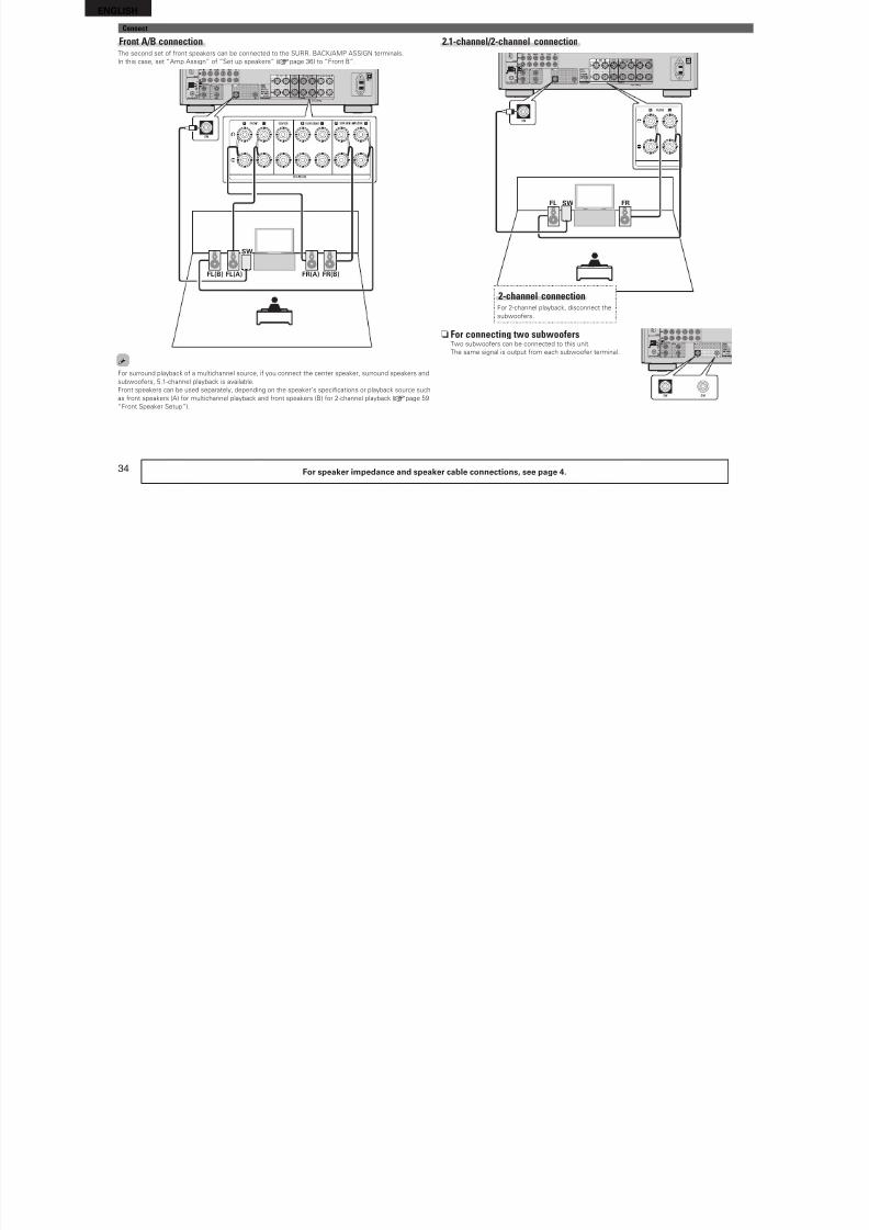
8/7/2019 IBJSC.com | I-WEB.com.vn - 953467670
http://slidepdf.com/reader/full/ibjsccom-i-webcomvn-953467670 37/92
33
B a
s i c v e r s i o n
S i m p l e v e r s i o n
I n f o r m a t i o n
A d v a n c
e d v e r s i o n
Connect• For the method o connecting 5.1-channel speakers, see page 4.
• For the method o connecting the TV, see page 5.
7.1-channel (Front height speaker) connectionFor 7.1-channel (Front height speaker) playback, set “Amp Assign” in “Set up speakers” (vpage 36) to
“Front Height”.
FL FR
FHRFHL
C
SW
SL SR
7.1-channel/6.1-channel (Surround back speaker) connectionFor 7.1-channel (Surround back speaker) playback, set “Amp Assign” in “Set up speakers” (vpage 36) to
“Normal”.
FL FR
C
SBL SBR
SL SR
SW
6.1-channel connectionI using only one surround back speaker (with a 6.1-channel connection),
connect to the “L” side o the SURR. BACK/AMP ASSIGN terminal.
For speaker settings in this case, see “When 6.1ch (Surround back speaker)
installed” (vpage 32).
For speaker impedance and speaker cable connections, see page 4.
ENGLISH

8/7/2019 IBJSC.com | I-WEB.com.vn - 953467670
http://slidepdf.com/reader/full/ibjsccom-i-webcomvn-953467670 38/92
34
Connect
2.1-channel/2-channel connection
FL FRSW
2-channel connectionFor 2-channel playback, disconnect the
subwooers.
n For connecting two subwoofersTwo subwooers can be connected to this unit.
The same signal is output rom each subwooer terminal.
For speaker impedance and speaker cable connections, see page 4.
Front A/B connectionThe second set o ront speakers can be connected to the SURR. BACK/AMP ASSIGN terminals.
In this case, set “Amp Assign” o “Set up speakers” (vpage 36) to “Front B”.
FL(A)FL(B) FR(B)FR(A)
SW
For surround playback o a multichannel source, i you connect the center speaker, surround speakers andsubwooers, 5.1-channel playback is available.
Front speakers can be used separately, depending on the speaker’s specifcations or playback source such
as ront speakers (A) or multichannel playback and ront speakers (B) or 2-channel playback (vpage 59
“Front Speaker Setup”).
ENGLISH
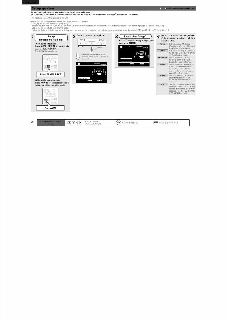
8/7/2019 IBJSC.com | I-WEB.com.vn - 953467670
http://slidepdf.com/reader/full/ibjsccom-i-webcomvn-953467670 39/92
35
B a
s i c v e r s i o n
S i m p l e v e r s i o n
I n f o r m a t i o n
A d v a n c
e d v e r s i o n
Bi-amp connectionA bi-amp connection is to connect separate amplifers to the tweeter terminals and wooer terminals ospeakers compatible with the bi-amp unction. This prevents the back electromotive orce (returned orcewithout output) o the wooer sent to the tweeter, which aects the sound quality o the tweeter, and youcan enjoy playback with higher-quality sound.
In this case, set “Amp Assign” o “Set up speakers” (vpage 36) to “Bi-Amp”.
FL FR
wq wq
(R)(L)
When making a bi-amp connection, the same signal is output rom the ront speaker terminal and the
SURR.BACK/AMP ASSIGN terminal. For surround playback o a multichannel source, i you connect the
center speaker, surround speakers and subwooers, 5.1-channel playback is available.
NOTE• Use speakers compatible with bi-amp connections.• When making bi-amp connections, be sure to remove the short-circuiti ng plate or wire between the
speaker’s wooer and tweeter terminals.
For speaker impedance and speaker cable connections, see page 4.
5.1-channel + 2.1-channel connectionI ront speakers or 2-channel playback are connected to the SURR. BACK / AMP ASSIGN terminals,
both speakers or multichannel playback and or 2-channel playback can be used, by switching.
In this case, set “Amp Assign” o “Set up speakers” (vpage 36) to “2CH”.
FLFL FR FR
C
SW
SL SR
Multi channel playback
2-channel playback(Direct/Stereo mode)
Switching
• For switching multichannel playback and 2-channel playback, see “Selecting a listening mode (Surround
mode)” (vpage 28).
• I “Audio Setup” – “2ch Direct/Stereo” – “Setting” (vpage 60) is set to “Custom”, settings or 2-channel
playback speakers can be made.
Connect
ENGLISH
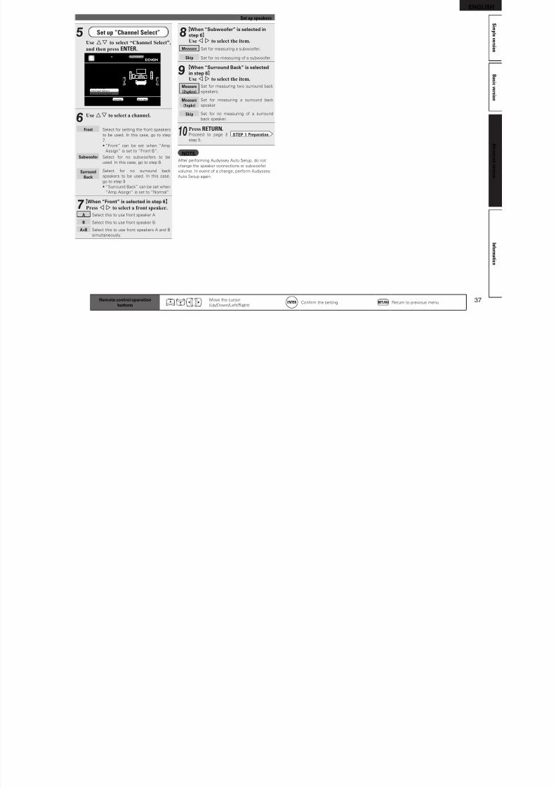
8/7/2019 IBJSC.com | I-WEB.com.vn - 953467670
http://slidepdf.com/reader/full/ibjsccom-i-webcomvn-953467670 40/92
36
3 Set up “Amp Assign”
Use ui to select “Amp Assign”, and
then press ENTER.
[1/6]STEP1 PreparationConnect the speakersand place them accord-ing to the recommenda-tions in the manual.Set the followingitems if necessary.
Set use of surround back ch. for your system
Amp AssignChannel SelectAuto Setup Start
AUTO SETUPAUDYSSEY AUTO SETUP MultEQ
ENTER Enter RETURN Cancel
Remote control operationbuttons
Move the cursor
(Up/Down/Let/Right)Confrm the setting Return to previous menu
4Use o p to select the conguration
of the connected speakers, and then
press RETURN.
Normal Set when using 7.1-channel
(Front/Center/Surround/Surround
Back/Subwooer) speakers.
ZONE2 Set or connecting the speakers
or ZONE2 to the SURR. BACK/
AMP ASSIGN terminals.
Front Height Set or connecting the ront
height speakers to the SURR.
BACK/AMP ASSIGN terminals.
Bi-Amp Set or connecting a tweeter o
a ront speaker to the SURR.
BACK/AMP ASSIGN terminals
and a wooer o the ront speaker
to the FRONT terminals.
Front B Set or connecting the second
set o ront speakers to the
SURR. BACK/AMP ASSIGN
terminals.
2CH Set or 2-channel direct/stereo
playback. When “2CH” is set,
connect the second set o ront
speakers to the SURR.BACK/
AMP ASSIGN terminals.
Here we describe how to set up speakers other than 5.1-channel speakers.For the method o setting up 5.1-channel speakers, see “Simple version”, “Set up speakers (Audyssey® Auto Setup)” (vpage 6).
First install and connect the speakers to this unit.
Beore Auto Setup measurement, the settings shown below can be made.
• Changing the amplifer assignment (Amp Assign )The signal output rom the SURR.BACK / AMP ASSIGN speaker terminal o this unit can be switched to match your speaker environment (vpage 36 “Set up “Amp Assign””).
• Setting the channels to be used (Channel Select)
I channels that are not to be used are set in advance, measurement or the set channels is skipped, and measuring time can be reduced (vpage 37 “Set up “Channel Select””).
1 Set up the remote control unit
n Set up the zone modePress ZONE SELECT to switch the
zone mode to “MAIN”.The “MAIN” indicator lights.
Press ZONE SELECT
n Set up the operation modePress AMP to set the remote control
unit to amplier operation mode.
Press AMP
2Connect the setup microphone.
When the setup microphone is
connected, the ollowing screen is
displayed.
[1/6]STEP1 PreparationConnect the speakersand place them accord-ing to the recommenda-tions in the manual.Set the followingitems if necessary.
Start Auto Setup
Amp AssignChannel SelectAuto Setup Start
AUTO SETUPAUDYSSEY AUTO SETUP MultEQ
ENTER Enter RETURN Cancel
Set up speakers around items indicate the settings.
ENGLISH

8/7/2019 IBJSC.com | I-WEB.com.vn - 953467670
http://slidepdf.com/reader/full/ibjsccom-i-webcomvn-953467670 41/92
37
B a
s i c v e r s i o n
S i m p l e v e r s i o n
I n f o r m a t i o n
A d v a n c e d v e r s i o n
Remote control operationbuttons
Move the cursor
(Up/Down/Let/Right)Confrm the setting Return to previous menu
5 Set up “Channel Select”
Use ui to select “Channel Select”,
and then press ENTER.
[1/6]STEP1 PreparationConnect the speakersand place them accord-ing to the recommenda-tions in the manual.
Set the followingitems if necessary.
Skip unused ch’s measurement for timesaving
Amp AssignChannel SelectAuto Setup Start
AUTO SETUPAUDYSSEY AUTO SETUP MultEQ
ENTER Enter RETURN Cancel
6Use ui to select a channel.
Front Select or setting the ront speakers
to be used. In this case, go to step
7.
• “Front” can be set when “Amp
Assign” is set to “Front B”.
Subwoofer Select or no subwooers to be
used. In this case, go to step 8.
Surround
Back
Select or no surround back
speakers to be used. In this case,
go to step 9.
• “Surround Back” can be set when
“Amp Assign” is set to “Normal”.
7GWhen “Front” is selected in step 6HPress o p to select a front speaker.
A Select this to use ront speaker A
B Select this to use ront speaker B.
A+B Select this to use ront speakers A and B
simultaneously.
Set up speakers
8GWhen “Subwooer” is selected instep 6HUse o p to select the item.
Measure Set or measuring a subwooer.
Skip Set or no measuring o a subwooer.
9GWhen “Surround Back” is selectedin step 6HUse o p to select the item.
Measure
(2spkrs)
Set or measuring two surround back
speakers.
Measure
(1spkr)
Set or measuring a surround back
speaker.
Skip Set or no measuring o a surround
back speaker.
10Press RETURN.Proceed to page 8 STEP 1 Preparation
step 5.
NOTE
Ater perorming Audyssey Auto Setup, do notchange the speaker connections or subwooer
volume. In event o a change, perorm Audyssey
Auto Setup again.
ENGLISH
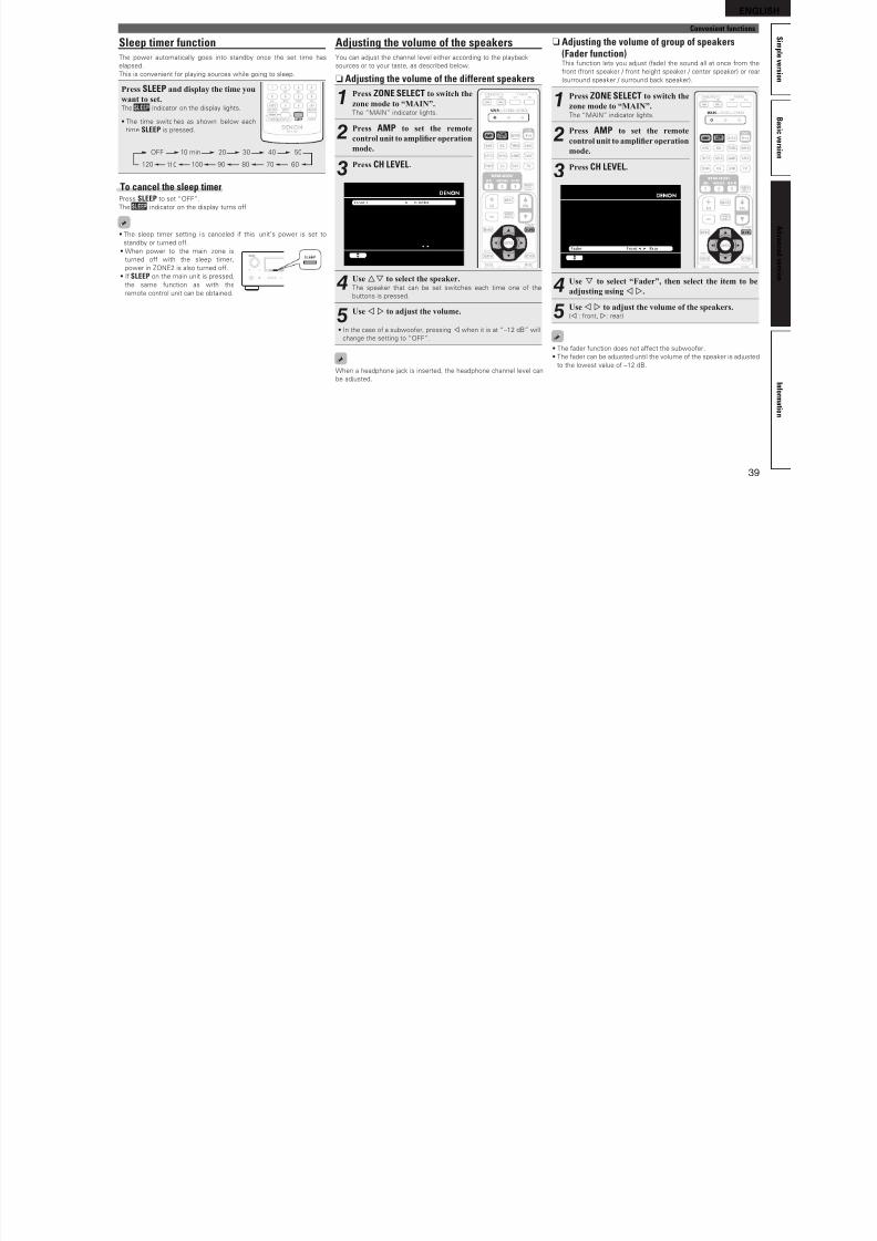
8/7/2019 IBJSC.com | I-WEB.com.vn - 953467670
http://slidepdf.com/reader/full/ibjsccom-i-webcomvn-953467670 42/92
38
n HDMI control function (vpage 38)
n Sleep timer function (vpage 39)
n Adjusting the volume of the speakers (vpage 39)
n Quick select function (vpage 40)
n REC OUT mode (vpage 40)
n Various memory functions (vpage 41)
Playback (Basic operation) (vpage 21)
Selecting a listening mode (Surround mode)(vpage 28)
Playback (Advanced operation)
Convenient functions
HDMI control functionWhen you make an HDMI connection with a TV or player compatible
with this unit and HDMI control unctions, you can perorm the
ollowing operations by setting the HDMI control unction o each
device.
n This unit power off can be linked to the TV power offstep.
n You can switch audio output devices with a TVoperation.When you set “Output audio rom amp” in the TV audio output
setup operation, you can switch the amp power on.
n You can adjust this unit volume in the TV volumeadjustment operation.
n You can switch this unit input sources throughlinkage to TV input switching.
n When playing the player, this unit input source
switches to the source for that player.
NOTE• When “HDMI Control” is set to “ON”, it consumes more
standby power.• The HDMI control unction controls operations o a TV that is
compatible with the HDMI control unction. Make sure that the TV
and HDMI are connected when you perorm HDMI control.
• Some unctions may not operate depending on the connected TV
or player. Check the owner’s manual o each device or details
beorehand.
• When “Power O Control” on the menu is set to “OFF” (vpage 60),
this unit is not set to standby even i the connected device is in the
standby mode.
• When connection changes are implemented, such as addingconnections to HDMI devices, linked operations may be initialized.
In this case, you will need to reconfgure the settings.
• When “HDMI Control” is set to “ON”, it is not possible to assign an
HDMI connector to “TV” at “Input Assign” (vpage 48).
1Set the HDMI output connector corresponding with
the HDMI control function.Set “HDMI Control” (vpage 60) to “ON“.
2Turn the power on for all the equipment connected
by HDMI cable.
3
Set the HDMI control function for all equipment
connected by HDMI cable.
• Please consult the operating i nstructions or the connected
equipment to check the settings.
• Carry out steps 1 and 2 should any o the equipment be unplugged.
4Switch the television input to the HDMI input
connected to this unit.
5Switch this unit input to the HDMI input source and
check if the picture from the player is ok.
6When you turn the TV’s power to standby, check
that the power of this unit also goes to standby.
I the HDMI control unction does not operate properly, check the
ollowing points.
• Is the TV or player compatible with the HDMI control unction?
• Is “HDMI Control” (vpage 60) set to “ON”?
• Is “Power O Control” (vpage 60) set to “All” or “Video”?
• Are the HDMI control unction settings o all equipment correct?
NOTEShould any o the operations below be perormed, the interlocking
unction may be reset, in which case, repeat steps 2 and 3.
• “Input Assign” – “HDMI” (vpage 48) setting has changed.
• There is a change to the connection between the equipment and the
HDMI, or an increase in equipment.
ENGLISH
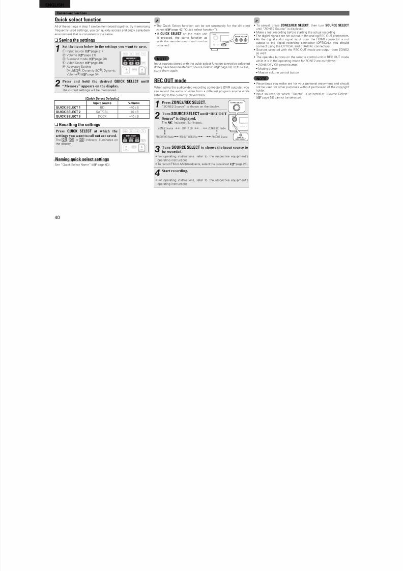
8/7/2019 IBJSC.com | I-WEB.com.vn - 953467670
http://slidepdf.com/reader/full/ibjsccom-i-webcomvn-953467670 43/92
39
B a
s i c v e r s i o n
S i m p l e v e r s i o n
I n f o r m a t i o n
A d v a n c e d v e r s i o n
Convenient functions
Sleep timer functionThe power automatically goes into standby once the set time has
elapsed.
This is convenient or playing sources while going to sleep.
Press SLEEP and display the time you
want to set.The indicator on the display lights.
• The time switches as shown below each
time SLEEP is pressed.
OFF 10 min 20 30 40 50
6080 7090100110120
To cancel the sleep timerPress SLEEP to set “OFF”.
The indicator on the display turns o.
• The sleep timer setting i s canceled i this unit’s power is set to
standby or turned o.
• When power to the main zone isturned o with the sleep timer,
power in ZONE2 is also turned o.
• I SLEEP on the main unit is pressed,
the same unction as with the
remote control unit can be obtained.
Adjusting the volume of the speakersYou can adjust the channel level either according to the playback
sources or to your taste, as described below.
n Adjusting the volume of the different speakers
1Press ZONE SELECT to switch the
zone mode to “MAIN”.The “MAIN” indicator lights.
2Press AMP to set the remotecontrol unit to amplier operation
mode.
3Press CH LEVEL.
Front L
Front R
Center
Subwoofer
Surround L
Surround R
S.Back L
S.Back R
Fader
0.0dB
0.0dB
0.0dB
0.0dB
0.0dB
0.0dB
0.0dB
0.0dB
CHANNEL LEVEL
Select
Front Rear
4Use ui to select the speaker.The speaker that can be set switches each time one o the
buttons is pressed.
5Use o p to adjust the volume.
• In the case o a subwooer, pressing o when it is at “–12 dB” will
change the setting to “OFF”.
When a headphone jack is inserted, the headphone channel level can
be adjusted.
n Adjusting the volume of group of speakers(Fader function)This unction lets you adjust (ade) the sound all at once rom the
ront (ront speaker / ront height speaker / center speaker) or rear
(surround speaker / surround back speaker).
1Press ZONE SELECT to switch the
zone mode to “MAIN”.The “MAIN” indicator lights.
2Press AMP to set the remotecontrol unit to amplier operation
mode.
3Press CH LEVEL.
Front L
Front R
Center
Subwoofer
Surround L
Surround R
S.Back L
S.Back R
Fader
0.0dB
0.0dB
0.0dB
0.0dB
0.0dB
0.0dB
0.0dB
0.0dB
CHANNEL LEVEL
Select
Front Rear
4Use i to select “Fader”, then select the item to be
adjusting using o p.
5Use o p to adjust the volume of the speakers.(o : ront, p: rear)
• The ader unction does not aect the subwooer.
• The ader can be adjusted until the volume o the speaker is adjusted
to the lowest value o –12 dB.
ENGLISH
C i f i
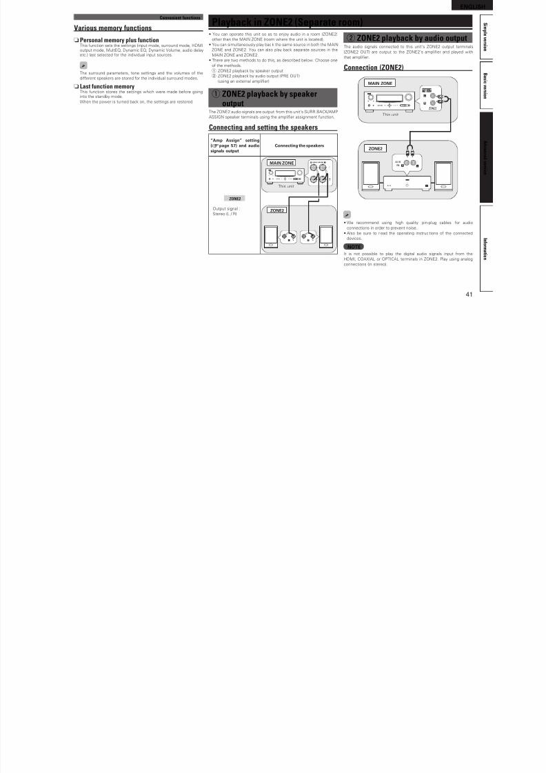
8/7/2019 IBJSC.com | I-WEB.com.vn - 953467670
http://slidepdf.com/reader/full/ibjsccom-i-webcomvn-953467670 44/92
40
Convenient functions
Quick select functionAll o the settings in step 1 can be memorized together. By memorizing
requently used settings, you can quickly access and enjoy a playback
environment that is consistently the same.
n Saving the settings
1Set the items below to the settings you want to save.
q Input source (vpage 21)
w Volume (vpage 21)
e Surround mode (vpage 28)r Video Select (vpage 49)
t Audyssey Setting
(MultEQ®, Dynamic EQ®, Dynamic
Volume®) (vpage 54)
2Press and hold the desired QUICK SELECT until
“Memory” appears on the display.The current settings will be memorized.
GQuick Select DeaultsHInput source Volume
QUICK SELECT 1 BD –40 dB
QUICK SELECT 2 SAT/CBL –40 dB
QUICK SELECT 3 DOCK –40 dB
n Recalling the settings
Press QUICK SELECT at which the
settings you want to call out are saved.The , or indicator illuminates on
the display.
Naming quick select settingsSee “Quick Select Name” (vpage 63).
• The Quick Select unc tion can be set separately or the di erent
zones (vpage 42 “Quick select unction”).
• I QUICK SELECT on the main unit
is pressed, the same unction as
with the remote control unit can be
obtained.
NOTEInput sources stored with the quick select unction cannot be selec tedi they have been deleted at “Source Delete” (vpage 62). In this case,store them again.
REC OUT modeWhen using the audio/video recording connectors (DVR outputs), you
can record the audio or video rom a dierent program source while
listening to the currently played track.
1Press ZONE2/REC SELECT.“ZONE2 Source” is shown on the display.
2
Turn SOURCE SELECT until “RECOUT
Source” is displayed.The indicator illuminates.
ZONE2 Source ZONE2 CD ZONE2 HD Radio····
RECOUT HD Radio RECOUT USB/iPod RECOUT Source····
3Turn SOURCE SELECT to choose the input source tobe recorded.
• For operating instructions, reer to the respective equipment’s
operating instructions.
• To record FM or AM broadcasts, select the broadcast (vpage 25).
4
Start recording.
• For operating instructions, reer to the respective equipment’s
operating instructions.
• To cancel, press ZONE2/REC SELECT, then turn SOURCE SELECT until “ZONE2 Source” is displayed.
• Make a test recording beore starting the actual recording.• The digital signals are not output to the anal og REC OUT connectors.• As the digital audio signal input rom the HDMI connector is not
output to the digital recording connector (OPTICAL), you shouldconnect using the OPTICAL and COAXIAL connectors.
• Sources selected with the REC OUT mode are output rom ZONE2as well.
• The operable buttons on the remote control unit in REC OUT mode
while it is in the operating mode or ZONE2 are as ollows:• ZONE/DEVICE power button
• Muting button
• Master volume control button
NOTE• Recordings you make are or your personal enjoyment and should
not be used or other purposes without permission o the copyrightholder.
• Input sources or which “Delete” is sel ected at “Source Delete”(vpage 62) cannot be selected.
ENGLISH
C i t f ti
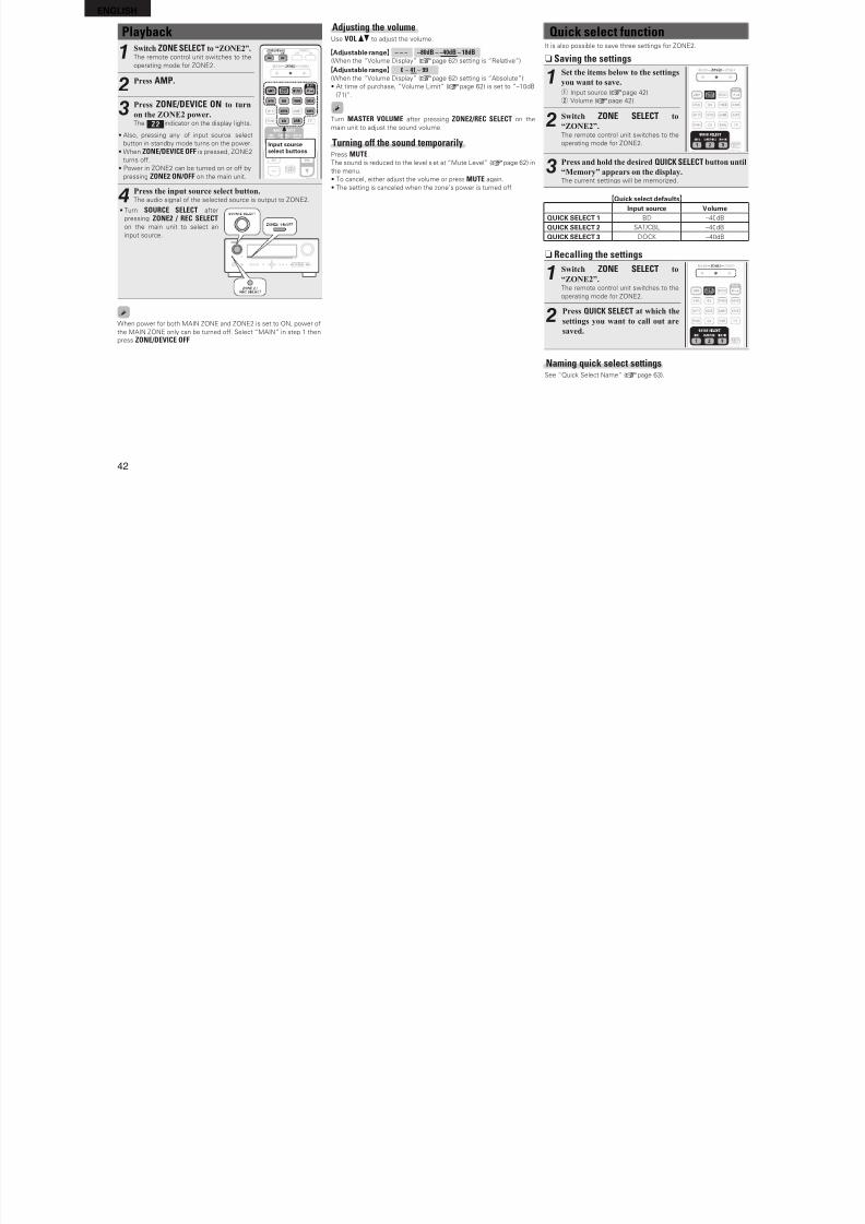
8/7/2019 IBJSC.com | I-WEB.com.vn - 953467670
http://slidepdf.com/reader/full/ibjsccom-i-webcomvn-953467670 45/92
41
B a s i c v e r s i o n
S i m p l e v e r s i o n
I n f o r m a t i o n
A d v a n c e d v e r s i o n
Playback in ZONE2 (Separate room)• You can operate this unit so as to enjoy audio in a room (ZONE2)
other than the MAIN ZONE (room where the unit is located).
• You can simultaneously play back the same source in both the MAIN
ZONE and ZONE2. You can also play back separate sources in the
MAIN ZONE and ZONE2.
• There are two methods to do this, as described below. Choose one
o the methods.
q ZONE2 playback by speaker output
w ZONE2 playback by audio output (PRE OUT)
(using an external amplifer)
q ZONE2 playback by speakeroutput
The ZONE2 audio signals are output rom this unit’s SURR.BACK/AMP
ASSIGN speaker terminals using the amplifer assignment unction.
Connecting and setting the speakers
“Amp Assign” setting(vpage 57) and audiosignals output
Connecting the speakers
ZONE2
Output signal :
Stereo (L / R)
MAIN ZONE
ZONE2
This unit
w ZONE2 playback by audio outputThe audio signals connected to this unit’s ZONE2 output terminals
(ZONE2 OUT) are output to the ZONE2’s amplifer and played with
that amplifer.
Connection (ZONE2)
R
L
R L
AUX
IN
This unit
MAIN ZONE
ZONE2
• We recommend using high quality pin-plug cables or audio
connections in order to prevent noise.
• Also be sure to read the operating instruc tions o the connected
devices.
NOTEIt is not possible to play the digital audio signals input rom the
HDMI, COAXIAL or OPTICAL terminals in ZONE2. Play using analog
connections (in stereo).
Convenient functions
Various memory functions
n Personal memory plus functionThis unction sets the settings (input mode, surround mode, HDMIoutput mode, MultEQ, Dynamic EQ, Dynamic Volume, audio delayetc.) last selected or the individual input sources.
The surround parameters, tone settings and the volumes o the
dierent speakers are stored or the individual surround modes.
n Last function memoryThis unction stores the settings which were made beore goinginto the standby mode.
When the power is turned back on, the settings are restored.
ENGLISH
Adjusting the volume Q f
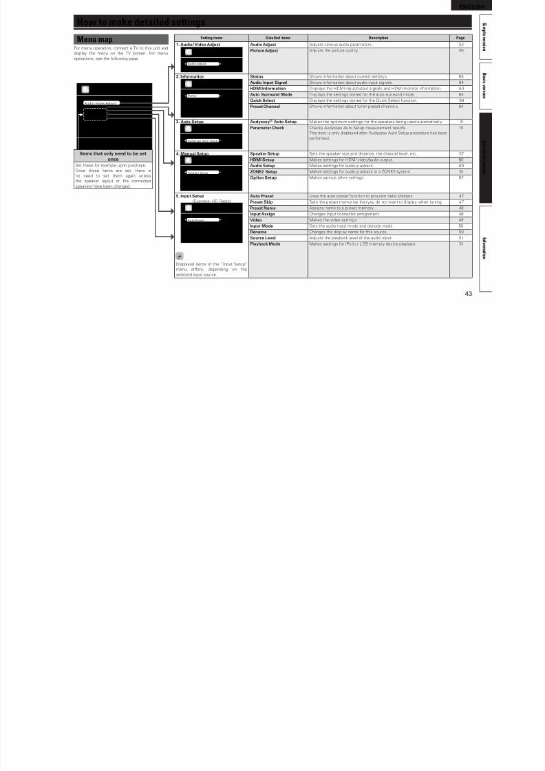
8/7/2019 IBJSC.com | I-WEB.com.vn - 953467670
http://slidepdf.com/reader/full/ibjsccom-i-webcomvn-953467670 46/92
42
Adjusting the volumeUse VOL df to adjust the volume.
GAdjustable rangeH – – – –80dB – –40dB – 18dB
(When the “Volume Display” (vpage 62) setting is “Relative”)
GAdjustable rangeH 0 – 41 – 99
(When the “Volume Display” (vpage 62) setting is “Absolute”)
• At time o purchase, “Volume Limit” (vpage 62) is set to “–10dB
(71)”.
Turn MASTER VOLUME ater pressing ZONE2/REC SELECT on the
main unit to adjust the sound volume.
Turning off the sound temporarilyPress MUTE.
The sound is reduced to the level set at “Mute Level” (vpage 62) in
the menu.
• To cancel, either adjust the volume or press MUTE again.
• The setting is canceled when the zone’s power is turned o.
Playback
1Switch ZONE SELECT to “ZONE2”.
The remote control unit switches to the
operating mode or ZONE2.
Input sourceselect buttons
2Press AMP.
3Press ZONE/DEVICE ON to turn
on the ZONE2 power.The indicator on the display lights.
• Also, pressing any o input source select
button in standby mode turns on the power.
• When ZONE/DEVICE OFF is pressed, ZONE2
turns o.
• Power in ZONE2 can be turned on or o by
pressing ZONE2 ON/OFF on the main unit.
4Press the input source select button.The audio signal o the selected source is output to ZONE2.
• Turn SOURCE SELECT ater
pressing ZONE2 / REC SELECT
on the main unit to select an
input source.
When power or both MAIN ZONE and ZONE2 is set to ON, power o
the MAIN ZONE only can be turned o. Select “MAIN” in step 1 then
press ZONE/DEVICE OFF.
Quick select functionIt is also possible to save three settings or ZONE2.
n Saving the settings
1Set the items below to the settings
you want to save.
q Input source (vpage 42)
w Volume (vpage 42)
2Switch ZONE SELECT to
“ZONE2”.The remote control unit switches to the
operating mode or ZONE2.
3Press and hold the desired QUICK SELECT button until
“Memory” appears on the display.The current settings will be memorized.
GQuick select deaultsHInput source Volume
QUICK SELECT 1 BD –40dB
QUICK SELECT 2 SAT/CBL –40dB
QUICK SELECT 3 DOCK –40dB
n Recalling the settings
1Switch ZONE SELECT to
“ZONE2”.The remote control unit switches to the
operating mode or ZONE2.
2Press QUICK SELECT at which the
settings you want to call out are
saved.
Naming quick select settings
See “Quick Select Name” (vpage 63).
ENGLISH
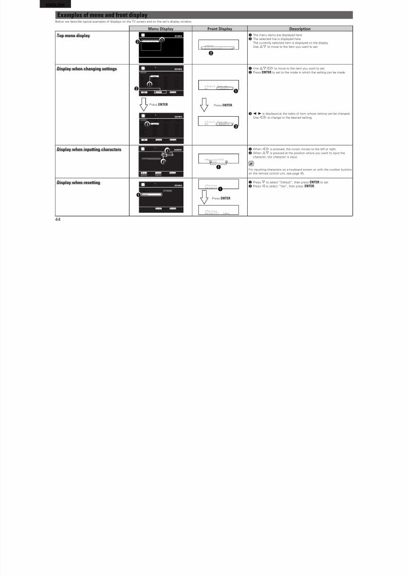
8/7/2019 IBJSC.com | I-WEB.com.vn - 953467670
http://slidepdf.com/reader/full/ibjsccom-i-webcomvn-953467670 47/92
43
B a s i c v e r s i o n
S i m p l e v e r s i o n
I n f o r m a t i o n
A d v a n c e d v e r s i o n
Menu mapFor menu operation, connect a TV to this unit and
display the menu on the TV screen. For menu
operations, see the ollowing page.
How to make detailed settings
Setting items Detailed items Description Page
1. Audio/Video Adjust
Audio Adjust
Picture Adjust
AUDIO/VIDEO ADJUST
Audio Adjust Adjusts various audio parameters. 52
Picture Adjust Adjusts the picture quality. 56
2. Inormation
Status
Audio Input Signal
HDMI Information
Auto Surround Mode
Quick Select
Preset Channel
INFORMATION
Status Shows inormation about current settings. 64
Audio Input Signal Shows inormation about audio input signals. 64
HDMI Inormation Displays the HDMI input/output signals and HDMI monitor inormation. 64
Auto Surround Mode Displays the settings stored or the auto surround mode. 64
Quick Select Displays the settings stored or the Quick Select unction. 64
Preset Channel Shows inormation about tuner preset channels. 64
3. Auto Setup
Audyssey Auto Setup
Parameter Check
AUTO SETUP
Audyssey® Auto Setup Makes the optimum settings or the speakers being used automatically. 6
Parameter Check Checks Audyssey Auto Setup measurement results.
This item is only displayed ater Audyssey Auto Setup procedure has been
perormed.
10
4. Manual Setup
Speaker Setup
HDMI Setup
Audio Setup
ZONE2 Setup
Option Setup
MANUAL SETUP
Speaker Setup Sets the speaker size and distance, the channel level, etc. 57
HDMI Setup Makes settings or HDMI video/audio output. 60
Audio Setup Makes settings or audio playback. 60
ZONE2 Setup Makes settings or audio playback in a ZONE2 system. 61
Option Setup Makes various other settings. 62
5. Input Setup(Example: HD Radio)
Auto Preset
Preset Skip
Preset Name
Video
Rename
Source Level
INPUT SETUP
Displayed items o the “Input Setup”
menu diers, depending on the
selected input source.
Auto Preset Uses the auto preset unction to program radio stations. 47
Preset Skip Sets the preset memories that you do not want to display when tuning. 47
Preset Name Assigns name to a preset memory. 48
Input Assign Changes input connector assignment. 48
Video Makes the video settings. 49
Input Mode Sets the audio input mode and decode mode. 50
Rename Changes the display name or this source. 50
Source Level Adjusts the playback level o the audio input. 51
Playback Mode Makes settings or iPod or USB memory device playback. 51
Adjust various audio and video parameters
Audio/Video Adjust
Information
Auto Setup
Manual Setup
Input Setup
MENU
Items that only need to be set
onceSet these or example upon purchase.
Once these items are set, there is
no need to set them again unless
the speaker layout or the connected
speakers have been changed.
ENGLISH
E l f d f t di l
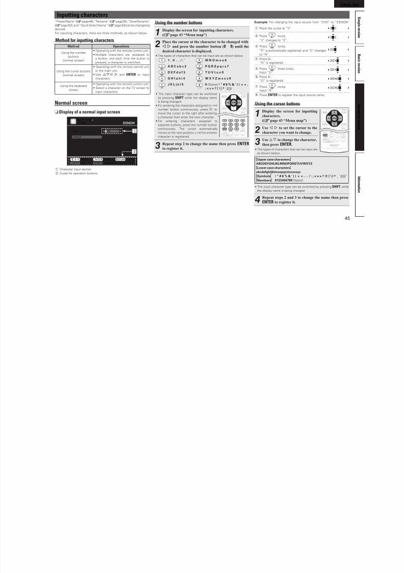
8/7/2019 IBJSC.com | I-WEB.com.vn - 953467670
http://slidepdf.com/reader/full/ibjsccom-i-webcomvn-953467670 48/92
44
Examples of menu and front displayBelow we describe typical examples o displays on the TV screen and on the set’s display window.
Menu Display Front Display Description
Top menu display
Adjust various audio and video parameters
Audio/Video AdjustInformation
Auto SetupManual Setup
Input Setup
MENU
qw
w
*MENU
A/V Adjust –
q The menu items are displayed here.
w The selected line is displayed here.
The currently selected item is displayed on the display.
Use ui to move to the item you want to set.
Display when changing settings
BDDVD
TVSAT/CBL
DVR
GAMEV.AUX
Change HDMI input connector assignment
INPUT SETUPINPUT ASSIGN
ENTER EnterSelect RETURN Return
Default
HDMI1HDMI2
None
HDMI3HDMI4
HDMI5HDMI6
[ HDMI ]
NoneCoax1
Opt1
Coax2Opt2
NoneNone
[ DIGITAL ]
None1-RCA
None
2-RCANone
NoneNone
[ COMP ]
qw
BDDVD
TVSAT/CBL
DVR
GAMEV.AUX
Assign HDMI 1 input connector
ENTER EnterSelect RETURN Cancel
Default
HDMI1HDMI2
NoneHDMI3
HDMI4
HDMI5HDMI6
[ HDMI ]
NoneCoax1
Opt1Coax2
Opt2
NoneNone
[ DIGITAL ]
None1-RCA
None2-RCA
None
NoneNone
[ COMP ]
INPUT SETUPINPUT ASSIGN
e
Press ENTER.
q*Input Assign
BD [HDMI1 ]
e*Input Assign
BD •HDMI1 –
Press ENTER.
q Use uio p to move to the item you want to set.
w Press ENTER to set to the mode in which the setting can be made.
e 0 1 is displayed at the sides o item whose setting can be changed.
Use o p to change to the desired setting.
Display when inputting charactersDVD
Default
DVD
INPUT SETUP
RENAME
RETURN CancelENTER,0-9 EnterInput
a/A KeyboardSH IF T SE ARC H
w
q
q
*Rename:DVD
•DVD –
q When o p is pressed, the cursor moves to the let or right.
w When ui is pressed at the position where you want to input the
character, the character is input.
For inputting characters on a keyboard screen or with the number buttons
on the remote control unit, see page 45.
Display when resetting
DVD
Default
DVD
INPUT SETUP
RENAME
RETURN ReturnENTER Enter
q
*Rename
Default? :•No
q*Rename
Default
Press ENTER.
q Press i to select “Deault”, then press ENTER to set.
w Press o to select “Yes”, then press ENTER.
ENGLISH
I tti h t
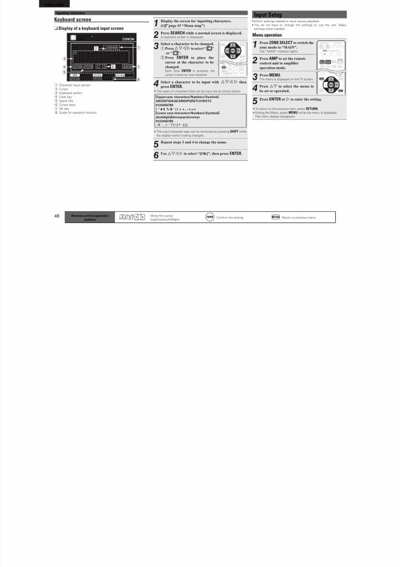
8/7/2019 IBJSC.com | I-WEB.com.vn - 953467670
http://slidepdf.com/reader/full/ibjsccom-i-webcomvn-953467670 49/92
45
B a s i c v e r s i o n
S i m p l e v e r s i o n
I n f o r m a t i o n
A d v a n c e d v e r s i o n
Inputting characters“Preset Name” (vpage 48), “Rename” (vpage 50), “Zone Rename”
(vpage 63), and “Quick Select Name” (vpage 63)can be changed as
desired.
For inputting characters, there are three methods, as shown below.
Method for inputting charactersMethod Operations
Using the number
buttons
(normal screen)
• Operating with the remote control unit.
• Multiple characters are assigned to
a button, and each time the button is
pressed, a character is switched.
Using the cursor buttons
(normal screen)
• Operating with the remote control unit
or the main unit.
• Use uio p and ENTER to input
characters.
Using the keyboard
screen
• Operating with the remote control unit.
• Select a character on the TV screen to
input characters.
Normal screen
nDisplay of a normal input screen
DVD
Default
INPUT SETUPRENAME
RETURN CancelENTER,0-9 EnterInput
a/A KeyboardSHIFT SEARCH
DVD q
w
q Character input section
w Guide or operation buttons
Using the number buttons
1Display the screen for inputting characters.
(vpage 43 “Menu map”)
2Place the cursor at the character to be changed with
o p and press the number button (0 – 9) until the
desired character is displayed.
• The types o characters that can be input are as shown below.
1 . @ - _ / : ̃ M N O m n o 6A B C a b c 2 P Q R S p q r s 7
D E F d e 3 T U V t u v 8
G H I g h i 4 W X Y Z w x y z 9
J K L j k l 5 0 (Space) ! “ # $ % & ‘ ( ) z + ,; < = > ? [ \ ] ^ ` { | }
• The input character type can be switched
by pressing SHIFT while the display name
is being changed.
• For entering the characters assigned to one
number button continuously, press p to
move the cursor to the right ater entering
a character then enter the next character.• For entering characters assigned to
separate buttons, press the number button
continuously. The cursor automatically
moves to the next position, and the entered
character is registered.
3Repeat step 2 to change the name then press ENTERto register it.
Example: For changing the input source rom “DVD” to “DENON”
qPlace the cursor at “V”. DVD
wPress twice.
DED
“V” changes to “E”.
ePress twice.
DEN“E” is automatically registered, and “D” changes
to “N”.
rPress
p. DEN“N” is registered.
tPress three times. DENO
Input “O”.
yPress p.DENO
“O” is registered.
uPress twice. DENON
Input “N”.
iPress ENTER to register the input source name.
Using the cursor buttons
1Display the screen for inputting
characters.(vpage 43 “Menu map”)
2Use o p to set the cursor to the
character you want to change.
3Use ui to change the character,
then press ENTER.
• The types o characters that can be input are
as shown below.
GUpper case charactersHABCDEFGHIJKLMNOPQRSTUVWXYZGLower case charactersHabcdeghijklmnopqrstuvwxyz
GSymbolsH ! “ # $ % & ‘ ( ) z + , - . / : ; < = > ? @ [ \ ] ^ _ ` { | } ˜ GNumbersH 0123456789 (Space)
• The input character type can be switched by pressing SHIFT while
the display name is being changed.
4Repeat steps 2 and 3 to change the name then press
ENTER to register it.
ENGLISH
I t S tInputting characters
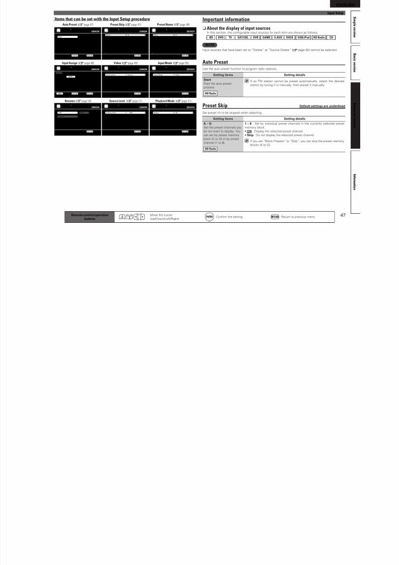
8/7/2019 IBJSC.com | I-WEB.com.vn - 953467670
http://slidepdf.com/reader/full/ibjsccom-i-webcomvn-953467670 50/92
46
Keyboard screen
nDisplay of a keyboard input screen
BDBD
INPUT SETUP
RENAME
RETURN CancelENTER InputSelect
a/A NormalSHIFT SEARCH
A
N
0
$
B
O
1
%
D
Q
3
’
E
R
4
(
L
Y
”
=
M
Z
#
>
G
T
6
z
F
S
5
)
H
U
7
+
I
V
8
,
K
X
!
<
J
W
9
;
C
P
2
&
Clear Space 0 1 O Kr
q
u
i
y
w
e
t
q Character input section
w Cursor
e Keyboard section
r Clear key
t Space key
y Cursor keys
u OK key
i Guide or operation buttons
1Display the screen for inputting characters.
(vpage 43 “Menu map”)
2Press SEARCH while a normal screen is displayed.A keyboard screen is displayed.
3Select a character to be changed.
qPressuio p to select “ ”
or “ ”.
wPress ENTER to place the
cursor at the character to be
changed.Each time ENTER is pressed, the
cursor moves by one character.
4Select a character to be input with uio p then
press ENTER.
• The types o characters that can be input are as shown below.
GUpper case characters/Numbers/SymbolsHABCDEFGHIJKLMNOPQRSTUVWXYZ0123456789! “ # $ % & ’ ( ) z + , ; < = >GLower case characters/Numbers/SymbolsH
abcdeghijklmnopqrstuvwxyz0123456789. @ - _ / : ˜ ? [ \ ] ^ ` { | }
• The input character type can be switched by pressing SHIFT while
the display name is being changed.
5Repeat steps 3 and 4 to change the name.
6Use uio p to select “[OK]”, then press ENTER.
Remote control operationbuttons
Move the cursor
(Up/Down/Let/Right)Confrm the setting Return to previous menu
Input SetupPerorm settings related to input source playback.
• You do not have to change the settings to use the unit. Make
settings when needed.
Menu operation
1Press ZONE SELECT to switch the
zone mode to “MAIN”.The “MAIN” indicator lights.
2Press AMP to set the remotecontrol unit to amplier
operation mode.
3Press MENU.The menu is displayed on the TV screen.
4Press ui to select the menu to
be set or operated.
5Press ENTER or p to enter the setting.
• To return to the previous item, press RETURN.
• Exiting the Menu, press MENU while the menu is displayed.
The menu display disappears.
Inputting characters
ENGLISH
Input Setup
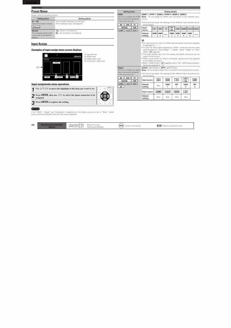
8/7/2019 IBJSC.com | I-WEB.com.vn - 953467670
http://slidepdf.com/reader/full/ibjsccom-i-webcomvn-953467670 51/92
47
B a s i c v e r s i o n
S i m p l e v e r s i o n
I n f o r m a t i o n
A d v a n c e
d v e r s i o n
Items that can be set with the Input Setup procedure
INPUT SETUPAUTO PRESET
Start the auto preset process
Start
ENTER Enter RETURN Return
Block
A Block PresetsA1 FM 87.50MHzA2 FM 87.90MHz
A3 FM 89.10MHzA4 FM 93.30MHzA5 FM 97.90MHz
A6 AM 98.10MHzA7 AM 98.90MHz
A8 AM 100.10MHz
A
ONONON
ONON
ONONON
ON
INPUT SETUPPRESET SKIP
Change memory blocks
RETURN Return
[1/7]
Block
A1 FM 87.50MHzA2 FM 87.90MHzA3 FM 89.10MHz
A4 FM 93.30MHzA5 FM 97.90MHzA6 AM 98.10MHz
A7 AM 98.90MHzA8 AM 100.10MHz
A
[ ][ ][ ]
[ ][ ]
[ ][ ][ ]
INPUT SETUPPRESET NAME
Change memory blocks
RETURN Return
[1/7]
BDDVDTV
SAT/CBLDVR
GAMEV.AUX
Change HDMI input connector assignment
INPUT SETUPINPUT ASSIGN
ENTER EnterSelect RETURN Return
Default
HDMI1HDMI2None
HDMI3HDMI4
HDMI5HDMI6
[ HDMI ]
NoneCoax1
Opt1Coax2Opt2
NoneNone
[ DIGITAL ]
None1-RCA
None2-RCANone
NoneNone
[ COMP ]
DVD
Default
DVD
INPUT SETUP
RENAME
RETURN Return
Video SelectVideo ModeVideo Convert
i/p ScalerResolution(Analog)Resolution(HDMI)
Progressive ModeAspect
SourceAutoON
Analog & HDMIAuto
AutoAutoFull
INPUT SETUPVIDEO
Select desired video input sourceRETURN Return
Analog Input
Digital Input
0dB
0dB
INPUT SETUPSOURCE LEVEL
Compensate analog audio input playback level
RETURN Return
Input ModeDecode Mode
AutoAuto
INPUT SETUPINPUT MODE
Automatically detect input signal and playbackRETURN Return
RepeatShuffle
AllOFF
INPUT SETUPPLAYBACK MODE
Repeat all songs
RETURN Return
Auto Preset (vpage 47)
Input Assign (vpage 48)
Rename (vpage 50)
Video (vpage 49)
Source Level (vpage 51)
Input Mode (vpage 50)
Playback Mode (vpage 51)
Preset Skip (vpage 47) Preset Name (vpage 48)
Remote control operationbuttons
Move the cursor
(Up/Down/Let/Right)Confrm the setting Return to previous menu
Important information
n About the display of input sourcesIn this section, the confgurable input sources or each item are shown as ollows.
BD DVD TV SAT/CBL DVR GAME V.AUX DOCK USB/iPod HD Radio CD
NOTEInput sources that have been set to “Delete” at “Source Delete” (vpage 62) cannot be selected.
Auto PresetUse the auto preset unction to program radio stations.
Setting items Setting details
StartStart the auto preset
process.
HD Radio
I an FM station cannot be preset automatically, select the desired
station by tuning it in manually, then preset it manually.
Preset Skip Deault settings are underlined.
Set preset ch to be skipped when selecting.
Setting items Setting details
A – GSet the preset channels you
do not want to display. You
can set by preset memory
block (A to G) or by preset
channel (1 to 8).
HD Radio
1 – 8 : Set by individual preset channels in the currently selected preset
memory block.
• ON : Display the selected preset channel.
• Skip : Do not display the selected preset channel.
I you set “Block Presets” to “Skip”, you can skip the preset memory
blocks (A to G).
Input Setup
ENGLISH
Input Setup
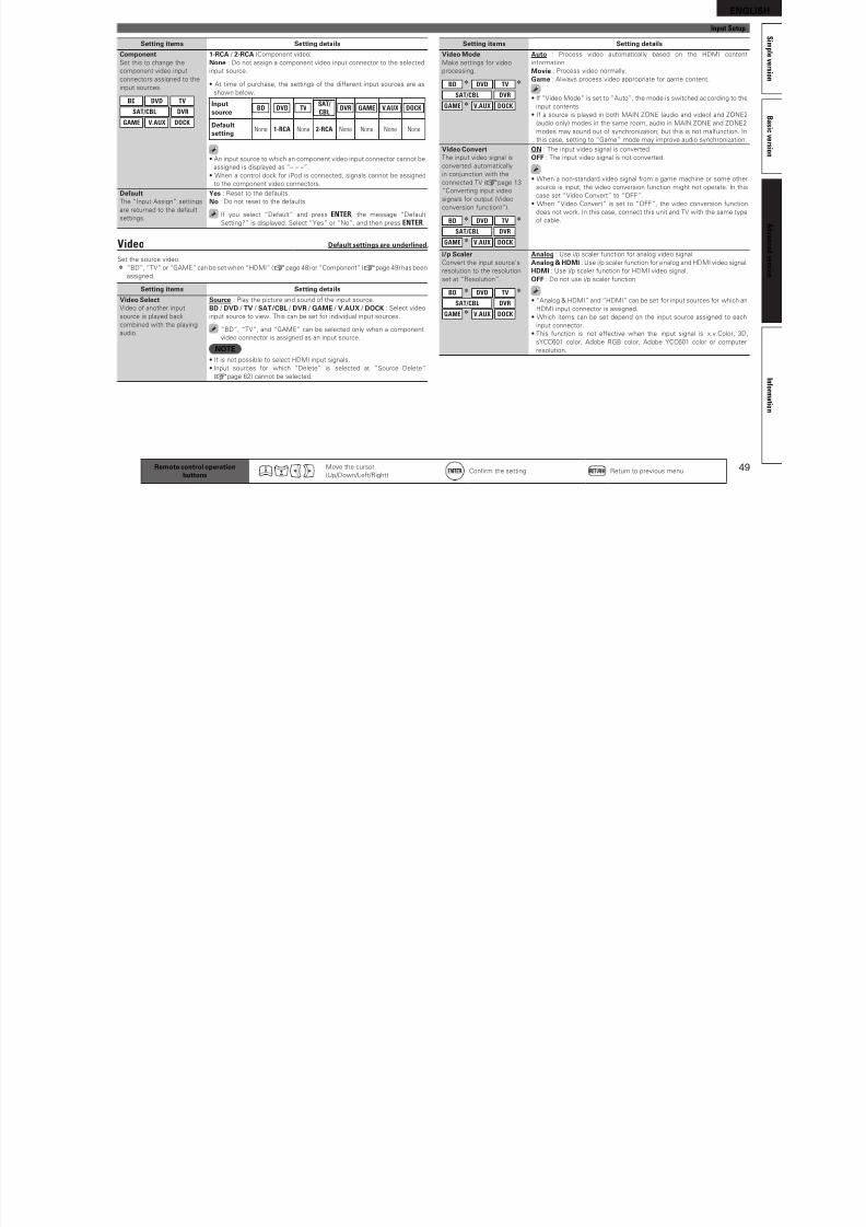
8/7/2019 IBJSC.com | I-WEB.com.vn - 953467670
http://slidepdf.com/reader/full/ibjsccom-i-webcomvn-953467670 52/92
48
Input Setup
Preset NameAssign name to a preset memory.
Setting items Setting details
A1 – G8Select the preset channel.
HD Radio
• Up to eight characters can be input.
• For character input, see page 45.
DeaultThe changed preset name
is returned to the deaultsetting.
Yes : Reset to the deaults.
No : Do not reset to the deaults.
Input Assign
Examples of input assign menu screen displays
BDDVD
TV
SAT/CBLDVR
GAME
V.AUX
Change HDMI input connector assignment
INPUT SETUPINPUT ASSIGN
ENTER EnterSelect RETURN Return
Default
HDMI1HDMI2
None
HDMI3HDMI4
HDMI5
HDMI6
[ HDMI ]
NoneCoax1
Opt1
Coax2Opt2
None
None
[ DIGITAL ]
None1-RCA
None
2-RCANone
None
None
[ COMP ]
q
ew r
q Input Source
w HDMI input
e Digital audio input
r Component video input
Input assignments menu operations
1Use uio p to move the highlight to the item you want to set.
2Press ENTER, then use o p to select the input connector to be
assigned.
3Press ENTER to register the setting.
NOTEI all “HDMI”, “Digital” and “Component” assignment o the Game source are set to “None”, Game
source cannot be selected with the input source selection.
Setting items Setting details
HDMISet this to change the HDMI
input connectors assigned
to the input sources.
BD DVD TV
SAT/CBL DVR
GAME V.AUX DOCK
HDMI 1 / HDMI 2 / HDMI 3 / HDMI 4 / HDMI 5 / HDMI 6None : Do not assign an HDMI input connector to the selected input
source.
• At time o purchase, the settings o the dierent input sources are as
shown below.
Inputsource
BD DVD TVSAT/
CBLDVR GAME V.AUX DOCK
Deaultsetting
HDMI
1
HDMI
2 NoneHDMI
3
HDMI
4
HDMI
5
HDMI
6 None
• An input source to which an HDMI input connector cannot be assigned
is displayed as “– – –”.
• To play the video signal assigned at “HDMI” combined with the audio
signal assigned at “Input Assign“ – “Digital”, select “Digital” at “Input
Mode” (vpage 50).
• The audio signals input rom the analog and digital connectors are not
output to the monitor.
• When a control dock or iPod is connected, signals cannot be assigned
to the HDMI connectors.
• When “HDMI Control” (vpage 60) is set to “ON”, HDMI input connector
cannot be assigned to “TV”.
DigitalSet this to change the digital
input connectors assigned
to the input sources.
BD DVD TV
SAT/CBL DVR
GAME V.AUX DOCK
CD
COAX1 – 2 (COAXIAL) / OPT1 – 2 (OPTICAL)None : Do not assign a digital input connector to the selected input source.
• At time o purchase, the settings o the dierent input sources are as
shown below.
Input source BD DVD TVSAT/
CBLDVR
Deaultsetting
NoneCOAX
1
OPT
1
COAX
2
OPT
2
Input source GAME V.AUX DOCK CD
Deaultsetting
None None None None
Remote control operationbuttons
Move the cursor
(Up/Down/Let/Right)Confrm the setting Return to previous menu
ENGLISH
Input Setup
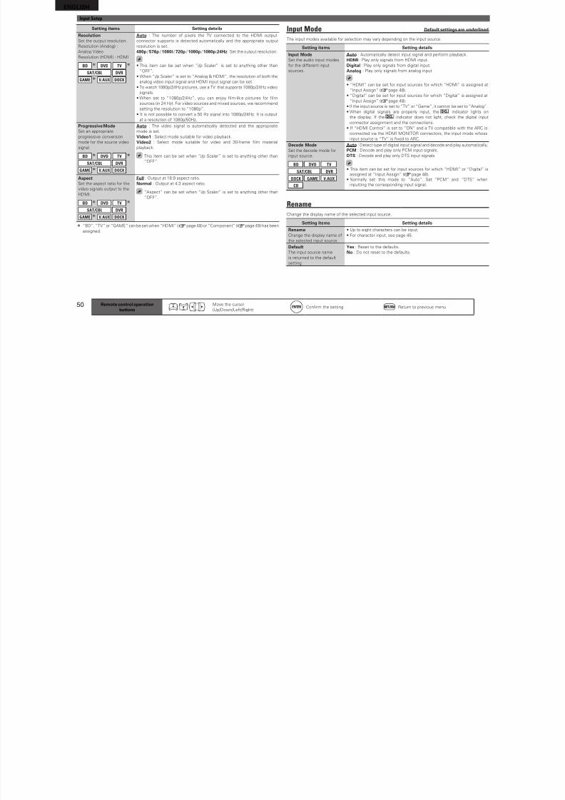
8/7/2019 IBJSC.com | I-WEB.com.vn - 953467670
http://slidepdf.com/reader/full/ibjsccom-i-webcomvn-953467670 53/92
49
B a s
i c v e r s i o n
S i m p l e v e r s i o n
I n f o r m a t i o n
A d v a n c e
d v e r s i o n
p p
Remote control operationbuttons
Move the cursor
(Up/Down/Let/Right)Confrm the setting Return to previous menu
Setting items Setting details
ComponentSet this to change the
component video input
connectors assigned to the
input sources.
BD DVD TV
SAT/CBL DVR
GAME V.AUX DOCK
1-RCA / 2-RCA (Component video)
None : Do not assign a component video input connector to the selected
input source.
• At time o purchase, the settings o the dierent input sources are as
shown below.
Inputsource
BD DVD TVSAT/
CBLDVR GAME V.AUX DOCK
Deaultsetting None 1-RCA None 2-RCA None None None None
• An input source to which an component video input connector cannot be
assigned is displayed as “– – –”.
• When a control dock or iPod is connected, signals cannot be assigned
to the component video connectors.
DeaultThe “Input Assign” settings
are returned to the deault
settings.
Yes : Reset to the deaults.
No : Do not reset to the deaults.
I you select “Deault” and press ENTER, the message “Deault
Setting?” is displayed. Select “Yes” or “No”, and then press ENTER.
Video Deault settings are underlined.
Set the source video.
z “BD”, “TV” or “GAME” can be set when “HDMI” (vpage 48) or “Component” (vpage 49) has been
assigned.
Setting items Setting details
Video SelectVideo o another input
source is played back
combined with the playing
audio.
Source : Play the picture and sound o the input source.
BD / DVD / TV / SAT/CBL / DVR / GAME / V.AUX / DOCK : Select video
input source to view. This can be set or individual input sources.
“BD”, “TV”, and “GAME” can be selected only when a component
video connector is assigned as an input source.
NOTE• It is not possible to select HDMI input signals.
• Input sources or which “Delete” is selected at “Source Delete”
(vpage 62) cannot be selected.
Setting items Setting details
Video ModeMake settings or video
processing.
BD z DVD TV z
SAT/CBL DVR
GAME z V.AUX DOCK
Auto : Process video automatically based on the HDMI content
inormation.
Movie : Process video normally.
Game : Always process video appropriate or game content.
• I “Video Mode” is set to “Auto”, the mode is switched according to the
input contents.
• I a source is played in both MAIN ZONE (audio and video) and ZONE2
(audio only) modes in the same room, audio in MAIN ZONE and ZONE2
modes may sound out o synchronization, but this is not malunction. Inthis case, setting to “Game” mode may improve audio synchronization.
Video ConvertThe input video signal is
converted automatically
in conjunction with the
connected TV (vpage 13
“Converting input video
signals or output (Video
conversion unction)”).
BD z DVD TV z
SAT/CBL DVR
GAME z V.AUX DOCK
ON : The input video signal is converted.
OFF : The input video signal is not converted.
• When a non-standard video signal rom a game machine or some other
source is input, the video conversion unction might not operate. In this
case set “Video Convert” to “OFF”.
• When “Video Convert” is set to “OFF”, the video conversion unction
does not work. In this case, connect this unit and TV with the same type
o cable.
i/p ScalerConvert the input source’s
resolution to the resolution
set at “Resolution”.
BD z DVD TV z
SAT/CBL DVR
GAME z V.AUX DOCK
Analog : Use i/p scaler unction or analog video signal.Analog & HDMI : Use i/p scaler unction or analog and HDMI video signal.
HDMI : Use i/p scaler unction or HDMI video signal.
OFF : Do not use i/p scaler unction.
• “Analog & HDMI” and “HDMI” can be set or input sources or which an
HDMI input connector is assigned.
• Which items can be set depend on the input source assigned to each
input connector.
• This unction is not eective when the input signal is x.v.Color, 3D,
sYCC601 color, Adobe RGB color, Adobe YCC601 color or computer
resolution.
ENGLISH
Input Setup
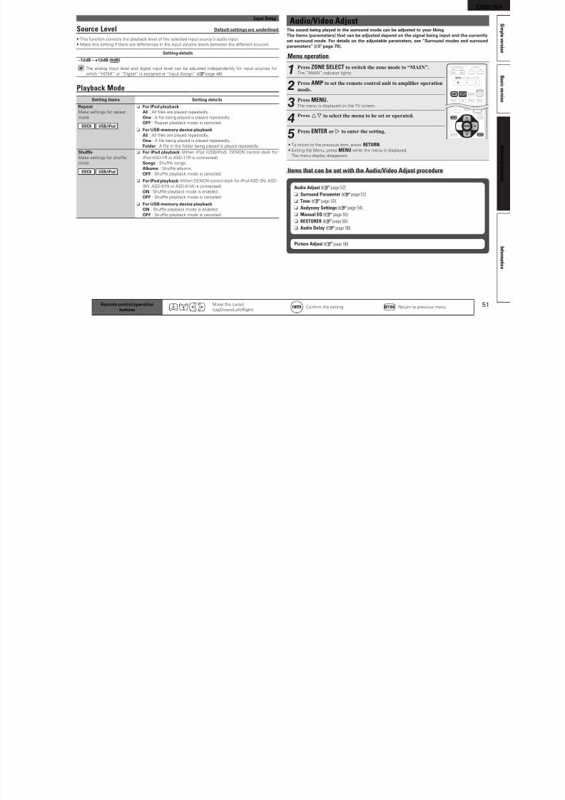
8/7/2019 IBJSC.com | I-WEB.com.vn - 953467670
http://slidepdf.com/reader/full/ibjsccom-i-webcomvn-953467670 54/92
50
p p
Remote control operationbuttons
Move the cursor
(Up/Down/Let/Right)Confrm the setting Return to previous menu
Setting items Setting details
ResolutionSet the output resolution.
Resolution (Analog) :
Analog Video
Resolution (HDMI) : HDMI
BD z DVD TV z
SAT/CBL DVR
GAME z V.AUX DOCK
Auto : The number o pixels the TV connected to the HDMI output
connector supports is detected automatically and the appropriate output
resolution is set.
480p / 576p / 1080i / 720p / 1080p / 1080p:24Hz : Set the output resolution.
• This item can be set when “i/p Scaler” is set to anything other than
“OFF”.
• When “i/p Scaler” is set to “Analog & HDMI”, the resolution o both the
analog video input signal and HDMI input signal can be set.
• To watch 1080p/24Hz pictures, use a TV that supports 1080p/24Hz video
signals.
• When set to “1080p/24Hz”, you can enjoy flm-like pictures or fl m
sources (in 24 Hz). For video sources and mixed sources, we recommend
setting the resolution to “1080p”.
• It is not possible to convert a 50 Hz signal into 1080p/24Hz. It is output
at a resolution o 1080p/50Hz.
Progressive ModeSet an appropriate
progressive conversion
mode or the source video
signal.
BD z DVD TV z
SAT/CBL DVR GAME z
V.AUX DOCK
Auto : The video signal is automatically detected and the appropriate
mode is set.
Video1 : Select mode suitable or video playback.
Video2 : Select mode suitable or video and 30-rame flm material
playback.
This item can be set when “i/p Scaler” is set to anything other than
“OFF”.
AspectSet the aspect ratio or the
video signals output to the
HDMI.
BD z DVD TV z
SAT/CBL DVR
GAME z V.AUX DOCK
Full : Output at 16:9 aspect ratio.
Normal : Output at 4:3 aspect ratio.
“Aspect” can be set when “i/p Scaler” is set to anything other than
“OFF”.
z “BD”, “TV” or “GAME” can be set when “HDMI” (vpage 48) or “Component” (vpage 49) has been
assigned.
Input Mode Deault settings are underlined.
The input modes available or selection may vary depending on the input source.
Setting items Setting details
Input ModeSet the audio input modes
or the dierent input
sources.
Auto : Automatically detect input signal and perorm playback.
HDMI : Play only signals rom HDMI input.
Digital : Play only signals rom digital input.
Analog : Play only signals rom analog input.
• “HDMI” can be set or input sources or which “HDMI” is assigned at“Input Assign” (vpage 48).
• “Digital” can be set or input sources or which “Digital” is assigned at
“Input Assign” (vpage 48).
• I the input source is set to “TV” or “Game”, it cannot be set to “Analog”.
• When digital signals are properly input, the indicator lights on
the display. I the indicator does not light, check the digital input
connector assignment and the connections.
• I “HDMI Control” is set to “ON” and a TV compatible with the ARC is
connected via the HDMI MONITOR connectors, the input mode whose
input source is “TV” is fxed to ARC.
Decode ModeSet the decode mode or
input source.
BD DVD TV SAT/CBL DVR
DOCK GAME V.AUX
CD
Auto : Detect type o digital input signal and decode and play automatically.
PCM : Decode and play only PCM input signals.
DTS : Decode and play only DTS input signals.
• This item can be set or input sources or which “HDMI” or “Digital” is
assigned at “Input Assign” (vpage 48).
• Normally set this mode to “Auto”. Set “PCM” and “DTS” when
inputting the corresponding input signal.
RenameChange the display name o the selected input source.
Setting items Setting details
RenameChange the display name o
the selected input source.
• Up to eight characters can be input.
• For character input, see page 45.
DeaultThe input source name
is returned to the deault
setting.
Yes : Reset to the deaults.
No : Do not reset to the deaults.
ENGLISH
Input Setup Audio/Video Adjust
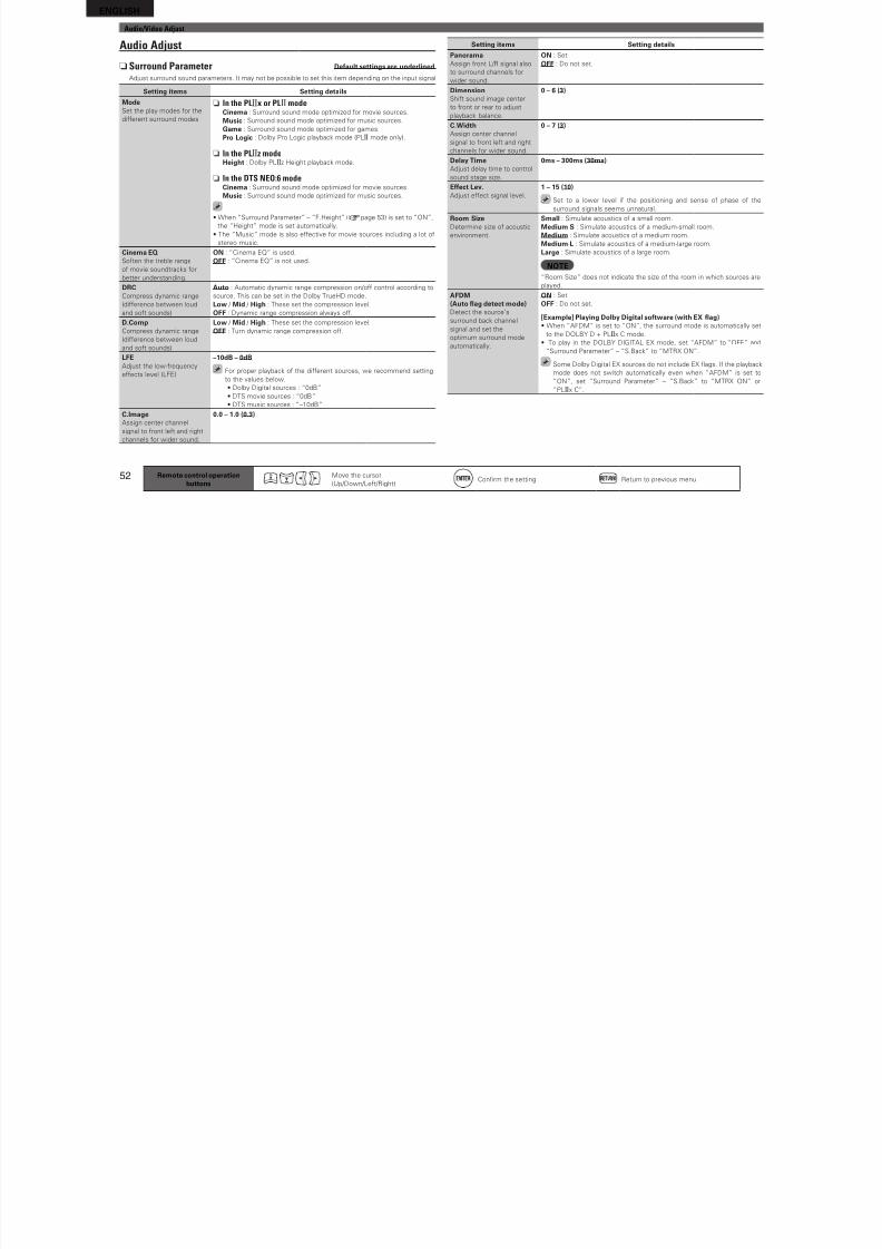
8/7/2019 IBJSC.com | I-WEB.com.vn - 953467670
http://slidepdf.com/reader/full/ibjsccom-i-webcomvn-953467670 55/92
51
B a s
i c v e r s i o n
S i m p l e v e r s i o n
I n f o r m a t i o n
A d v a n c e
d v e r s i o n
Source Level Deault settings are underlined.
• This unction corrects the playback level o the selected input source’s audio input.
• Make this setting i there are dierences in the input volume levels between the dierent sources.
Setting details
–12dB – +12dB (0dB)
The analog input level and digital input level can be adjusted independently or input sources or
which “HDMI” or “Digital” is assigned at “Input Assign“ (vpage 48).
Playback Mode
Setting items Setting details
RepeatMake settings or repeat
mode.
DOCK USB/iPod
n For iPod playbackAll : All fles are played repeatedly.
One : A fle being played is played repeatedly.
OFF : Repeat playback mode is canceled.
n For USB memory device playbackAll : All fles are played repeatedly.
One : A fle being played is played repeatedly.
Folder : A fle in the older being played is played repeatedly.
ShueMake settings or shue
mode.DOCK USB/iPod
n For iPod playback (When iPod (USB/iPod), DENON control dock or
iPod ASD-1R or ASD-11R is connected)
Songs : Shue songs.Albums : Shue albums.
OFF : Shue playback mode is canceled.
n For iPod playback (When DENON control dock or iPod ASD-3N, ASD-
3W, ASD-51N or ASD-51W is connected)
ON : Shue playback mode is enabled.
OFF : Shue playback mode is canceled.
n For USB memory device playbackON : Shue playback mode is enabled.
OFF : Shue playback mode is canceled.
Remote control operationbuttons
Move the cursor
(Up/Down/Let/Right)Confrm the setting Return to previous menu
Audio/Video AdjustThe sound being played in the surround mode can be adjusted to your liking.The items (parameters) that can be adjusted depend on the signal being input and the currentlyset surround mode. For details on the adjustable parameters, see “Surround modes and surroundparameters” (vpage 75).
Menu operation
1Press ZONE SELECT to switch the zone mode to “MAIN”.The “MAIN” indicator lights.
2Press AMP to set the remote control unit to amplier operationmode.
3Press MENU.The menu is displayed on the TV screen.
4Press ui to select the menu to be set or operated.
5Press ENTER or p to enter the setting.
• To return to the previous item, press RETURN.
• Exiting the Menu, press MENU while the menu is displayed.
The menu display disappears.
Items that can be set with the Audio/Video Adjust procedure
Audio Adjust (vpage 52)
n Surround Parameter (vpage 52)
n Tone (vpage 53)
n Audyssey Settings (vpage 54)
n Manual EQ (vpage 55)
n RESTORER (vpage 56)
n Audio Delay (vpage 56)
Picture Adjust (vpage 56)
ENGLISH
Audio/Video Adjust
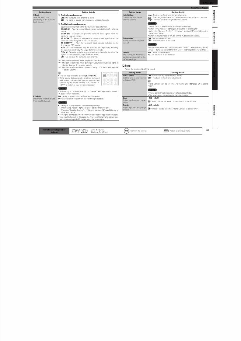
8/7/2019 IBJSC.com | I-WEB.com.vn - 953467670
http://slidepdf.com/reader/full/ibjsccom-i-webcomvn-953467670 56/92
52
Audio Adjust
n Surround Parameter Deault settings are underlined.
Adjust surround sound parameters. It may not be possible to set this item depending on the input signal
Setting items Setting details
ModeSet the play modes or the
dierent surround modes.
n In the PLgx or PLg modeCinema : Surround sound mode optimized or movie sources.
Music : Surround sound mode optimized or music sources.
Game : Surround sound mode optimized or games.
Pro Logic : Dolby Pro Logic playback mode (PLg mode only).
n In the PLgz modeHeight : Dolby PLgz Height playback mode.
n In the DTS NEO:6 modeCinema : Surround sound mode optimized or movie sources.
Music : Surround sound mode optimized or music sources.
• When “Surround Parameter” – “F.Height” (vpage 53) is set to “ON”,
the “Height” mode is set automatically.
• The “Music” mode is also eective or movie sources including a lot o
stereo music.
Cinema EQSoten the treble range
o movie soundtracks or
better understanding.
ON : “Cinema EQ” is used.
OFF : “Cinema EQ” is not used.
DRCCompress dynamic range
(dierence between loud
and sot sounds).
Auto : Automatic dynamic range compression on/o control according to
source. This can be set in the Dolby TrueHD mode.
Low / Mid / High : These set the compression level.
OFF : Dynamic range compression always o.
D.CompCompress dynamic range
(dierence between loud
and sot sounds).
Low / Mid / High : These set the compression level.
OFF : Turn dynamic range compression o.
LFEAdjust the low-requency
eects level (LFE).
–10dB – 0dB
For proper playback o the dierent sources, we recommend setting
to the values below.
• Dolby Digital sources : “0dB”
• DTS movie sources : “0dB”
• DTS music sources : “–10dB”
C.ImageAssign center channel
signal to ront let and right
channels or wider sound.
0.0 – 1.0 (0.3)
Remote control operationbuttons
Move the cursor
(Up/Down/Let/Right)Confrm the setting Return to previous menu
Setting items Setting details
PanoramaAssign ront L/R signal also
to surround channels or
wider sound.
ON : Set.
OFF : Do not set.
DimensionShit sound image center
to ront or rear to adjust
playback balance.
0 – 6 (3)
C.Width
Assign center channelsignal to ront let and right
channels or wider sound.
0 – 7 (3)
Delay TimeAdjust delay time to control
sound stage size.
0ms – 300ms (30ms)
Eect Lev.Adjust eect signal level.
1 – 15 (10)
Set to a lower level i the positioning and sense o phase o the
surround signals seems unnatural.
Room SizeDetermine size o acoustic
environment.
Small : Simulate acoustics o a small room.
Medium-S : Simulate acoustics o a medium-small room.
Medium : Simulate acoustics o a medium room.
Medium-L : Simulate acoustics o a medium-large room.
Large : Simulate acoustics o a large room.
NOTE“Room Size” does not indicate the size o the room in which sources are
played.
AFDM(Auto ag detect mode)Detect the source’s
surround back channel
signal and set the
optimum surround mode
automatically.
ON : Set.
OFF : Do not set.
[Example] Playing Dolby Digital sotware (with EX ag)• When “AFDM” is set to “ON”, the surround mode is automatically set
to the DOLBY D + PLgx C mode.
• To play in the DOLBY DIGITAL EX mode, set “AFDM” to “OFF” and
“Surround Parameter” – “S.Back” to “MTRX ON”.
Some Dolby Digital EX sources do not include EX ags. I the playback
mode does not switch automatically even when “AFDM” is set to
“ON”, set “Surround Parameter” – “S.Back” to “MTRX ON” or“PLgx C”.
ENGLISH
Audio/Video Adjust
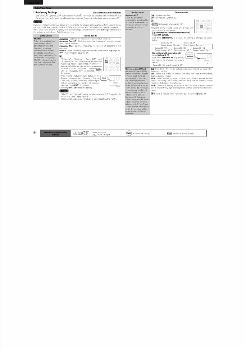
8/7/2019 IBJSC.com | I-WEB.com.vn - 953467670
http://slidepdf.com/reader/full/ibjsccom-i-webcomvn-953467670 57/92
53
B a s
i c v e r s i o n
S i m p l e v e r s i o n
I n f o r m a t i o n
A d v a n c e
d v e r s i o n
Remote control operationbuttons
Move the cursor
(Up/Down/Let/Right)Confrm the setting Return to previous menu
Setting items Setting details
S.BackSets the method o
generating o the surround
back channel.
n For 2-channel sourcesON : The surround back channel is used.
OFF : No signal is played rom the surround back channels.
n For Multi-channel sourcesSet the decoding method or the surround back channel.
DSCRT ON : Play the surround back signals i ncluded in the 7.1-channel
source.
MTRX ON : Generate and play the surround back signals rom the
surround channel signals.ES MTRXz1 : Generate and play the surround back signals rom the
surround channel signals o the DTS source.
ES DSCRTz2 : Play the surround back signals included in the
6.1-channel DTS source.
PLgx Cz3 : Generate and play the surround back signals by decoding
the signals in the Dolby Pro Logic gx Cinema mode.
PLgx M : Generate and play the surround back signals by decoding the
signals in the Dolby Pro Logic gx Music mode.
OFF : Do not play the surround back channel.
z1 This can be selected when playing DTS sources.
z2 This can be selected when playing DTS sources including a signal to
identiy discrete 6.1-channel signals.
z3 This can be selected when “Speaker Confg.” – “S.Back” (vpage 58)
is set to “2spkrs”.
• This can also be set by pressing STANDARD.
• I the source being played contains a surround
back signal, the decoder type is automatically
selected by the AFDM unction. Set “AFDM” to
“OFF” to switch to your preerred decoder.
NOTEI the setting in “Speaker Confg.” – “S.Back” (vpage 58) is “None”,
“S.Back” is not displayed.
F.HeightDetermine whether to use
ront height channel.
ON : Audio is output rom the ront height speaker.
OFF : Audio is not output rom the ront height speaker.
NOTE• “F.Height” is displayed or the ollowing settings.
• When “Amp Assign” (vpage 57) is set to “Front Height”.
• When the “Speaker Confg.” – “F.Height” setting (vpage 58) is set to
other than “None”.
• “F.Height” cannot be set i the HD Audio source being played includes a
ront height channel. In this case, the Front height channel is played back
without decoding in PLgz mode, using the input signal.
Setting items Setting details
Height GainControl the ront height
channel volume.
Low : Reduce the ront height channel volume.
Mid : Front height channel sound is output with standard sound volume.
High : Increase the ront height channel volume.
NOTE“Height Gain” is displayed or the ollowing settings.
• When “Amp Assign” (vpage 57) is set to “Front Height”.
• When the “Speaker Confg.” – “F.Height” sett ing (vpage 58) is set to
other than “None”.
• When surround mode is “PLgz” or the PLgz decoder is used.SubwooerTurn subwooer output on
and o.
ON : The subwooer is used.
OFF : The subwooer is not used.
NOTEThis can be set when the surround mode is “DIRECT” (vpage 30), “PURE
DIRECT” (vpage 30) and the “SW Mode” (vpage 58) is “LFE+Main”.
DeaultThe “Surround Parameter”
settings are returned to the
deault settings.
Yes : Reset to the deaults.
No : Do not reset to the deaults.
n ToneAdjust the tonal quality o the sound.
Setting items Setting details
Tone ControlSet the tone control unction
to ON and OFF.
ON : Allow tone adjustment (bass, treble).
OFF : Playback without tone adjustment.
“Tone Control” can be set when “Dynamic EQ” (vpage 54) is set to
“OFF”.
NOTE• “Tone Control” settings are not reected to ZONE2.
• The tone cannot be adjusted in the direct mode.
BassAdjust low requency range
(bass).
–6dB – +6dB
“Bass” can be set when “Tone Control” is set to “ON”.
TrebleAdjust high requency range
(treble).
–6dB – +6dB
“Treble” can be set when “Tone Control” is set to “ON”.
ENGLISH
Audio/Video Adjust
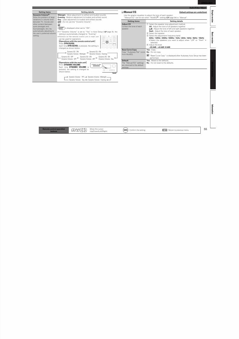
8/7/2019 IBJSC.com | I-WEB.com.vn - 953467670
http://slidepdf.com/reader/full/ibjsccom-i-webcomvn-953467670 58/92
54 Remote control operationbuttons
Move the cursor
(Up/Down/Let/Right)Confrm the setting Return to previous menu
nAudyssey Settings Deault settings are underlined.
Set MultEQ®, Dynamic EQ® and Dynamic Volume®. These can be selected ater Audyssey® Auto
Setup has been perormed. For additional inormation on Audyssey technology, please see page 80.
NOTEI you have not perormed Auto Setup, or i you change the speaker settings ater perorming Auto Setup,
you may not be able to select Dynamic EQ/Dynamic Volume, and “Run Audyssey” may be displayed.
In this case, either perorm Audyssey Auto Setup over again or perorm “Restore” (vpage 10) to return to
the settings ater Audyssey Auto Setup was run.
Setting items Setting details
MultEQSelect one equalizer rom
three modes. MultEQ
corrects both time and
requency response
problems in the listening
area based on Audyssey
Auto Setup calibration. We
recommend “Audyssey”.
MultEQ is the prerequisite
unction or Dynamic EQ
and Dynamic Volume.
Audyssey : Optimize the requency response o all speakers.
Audyssey Byp.L/R : Optimize requency response o speakers except
ront L and R speakers.
Audyssey Flat : Optimize requency response o all speakers to at
response.
Manual : Apply requency response set with “Manual EQ” (vpage 55).
OFF : Turn “MultEQ” equalizer o.
• “Audyssey”, “Audyssey Byp. L/R” and
“Audyssey Flat” can be selected ater Audyssey
Auto Setup has been perormed. “Audyssey” is
automatically selected ater perorming Audyssey
Auto Setup. When “Audyssey”, “Audyssey Byp.
L/R” or “Audyssey Flat” is selected,
illuminates.
• Ater running Audyssey Auto Setup, i the
Speaker Confguration, Distance, Channel
Level, and Crossover Frequency have changed
without increasing the number o speakers
measured, only illuminates.
• Pressing MULTEQ makes this setting.
NOTE• “MultEQ” and “Manual” cannot be selected when “EQ Customize” is
set to “Not Used” (vpage 61).
• When using headphones, “MultEQ” is automatically set to “OFF”.
Setting items Setting details
Dynamic EQ®
Solve the problem o
deteriorating sound quality
as volume is decreased by
taking into account human
perception and room
acoustics.
ON : Use Dynamic EQ.
OFF : Do not use Dynamic EQ.
• is displayed when set to “ON”.
• Buttons on the remote control unit or main unit
can be used or operations.
GOperations with the remote control unitHPress DYN EQ/VOL.
Each time DYN EQ/VOL is pressed, the setting is changed as shown
below.
Dynamic EQ : ON
Dynamic Volume : Midnight
Dynamic EQ : ON
Dynamic Volume : Evening
Dynamic EQ : ON
Dynamic Volume : OFF
Dynamic EQ : OFF
Dynamic Volume : OFF
Dynamic EQ : ON
Dynamic Volume : Day
GOperations with the main unitHPress DYNAMIC EQ.Each time DYNAMIC EQ is pressed,
the setting is changed as shown
below.
D yn ami c E Q : O N D yn am ic E Q : O FF
Reerence Level Oset
Audyssey Dynamic EQ isreerenced to the standard
flm mix level. It makes
adjustments to maintain
the reerence response
and surround envelopment
when the volume is turned
down rom 0 dB. However,
flm reerence level is not
always used in music or
other non-flm content.
Dynamic EQ Reerence
Level Oset provides three
osets rom the flm level
reerence (5 dB, 10 dB, and
15 dB) that can be selectedwhen the mix level o the
content is not within the
standard.
0dB (Film Re) : This is the deault setting and should be used when
listening to movies.5dB : Select this setting or content that has a very wide dynamic range,
such as classical music.
10dB : Select this setting or jazz or other music that has a wider dynamic
range. This setting should also be selected or TV content as that is usually
mixed at 10 dB below flm reerence.
15dB : Select this setting or pop/rock music or other program material
that is mixed at very high listening levels and has a compressed dynamic
range.
Setting is enabled when “Dynamic EQ” is “ON” (vpage 54).
ENGLISH
Audio/Video Adjust
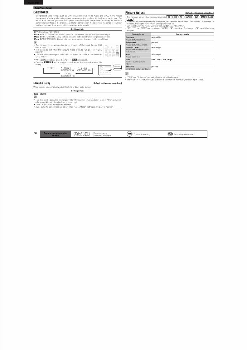
8/7/2019 IBJSC.com | I-WEB.com.vn - 953467670
http://slidepdf.com/reader/full/ibjsccom-i-webcomvn-953467670 59/92
55
B a s
i c v e r s i o n
S i m p l e v e r s i o n
I n f o r m a t i o n
A d v a n c e
d v e r s i o n
Remote control operationbuttons
Move the cursor
(Up/Down/Let/Right)Confrm the setting Return to previous menu
Setting items Setting details
Dynamic Volume®
Solve the problem o large
variations in volume level
between TV, movies and
other content (between
quiet passages and
loud passages, etc.) by
automatically adjusting to
the user’s preerred volume
setting.
Midnight : Most adjustment to sotest and loudest sounds.
Evening : Medium adjustment to loudest and sotest sound.
Day : Least adjustment to loudest and sotest sounds.
OFF : Do not use the “Dynamic Volume”.
• is displayed when set to “ON”.
• I “Dynamic Volume” is set to “Yes” in Auto Setup (vpage 9), the
setting is automatically changed to “Evening”.
• Buttons on the remote control unit or main unitcan be used or operations.
GOperations with the remote control unitHPress DYN EQ/VOL.
Each time DYN EQ/VOL is pressed, the setting is
changed as shown below.
Dynamic EQ : ON
Dynamic Volume : Midnight
Dynamic EQ : ON
Dynamic Volume : Evening
Dynamic EQ : ON
Dynamic Volume : OFF
Dynamic EQ : OFF
Dynamic Volume : OFF
Dynamic EQ : ON
Dynamic Volume : Day
GOperations with the main unitHPress DYNAMIC VOLUME.Each time DYNAMIC VOLUME is
pressed, the setting is changed asshown below.
Dynamic Volume : Midnight
Dynamic Volume : Evening
Dynamic Volume : OFF
Dynamic Volume : Day
n Manual EQ Deault settings are underlined.
Use the graphic equalizer to adjust the tone o each speaker.
“Manual EQ” can be set when “MultEQ®” setting (vpage 54) is “Manual”.
Setting items Setting details
Adjust CHCorrect the tone o each
speaker.
q Select the speaker tone adjustment method.
All : Adjust the tone o all speakers together.
L/R : Adjust the tone o let and right speakers together.
Each : Adjust the tone o each speaker.
w Select the speaker.
e Select the adjustment requency band.63Hz / 125Hz / 250Hz / 500Hz / 1kHz / 2kHz / 4kHz / 8kHz / 16kHz• Select the speakers you want to adjust when “L/R” or “Each” is
selected.
r Adjust the level.
–20.0dB – +6.0dB (0.0dB)
Base Curve CopyCopy “Audyssey Flat” curve
rom MultEQ.
Yes : Copy.
No : Do not copy.
“Base Curve Copy” is displayed ater Audyssey Auto Setup has been
perormed.
DeaultThe “Manual EQ” settings
are returned to the deault
settings.
Yes : Reset to the deaults.
No : Do not reset to the deaults.
ENGLISH
Audio/Video Adjust
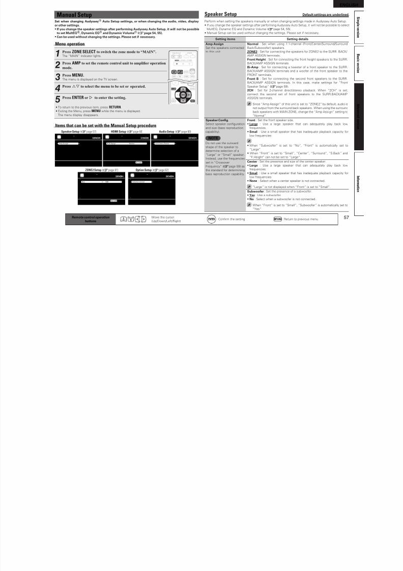
8/7/2019 IBJSC.com | I-WEB.com.vn - 953467670
http://slidepdf.com/reader/full/ibjsccom-i-webcomvn-953467670 60/92
56 Remote control operationbuttons
Move the cursor
(Up/Down/Let/Right)Confrm the setting Return to previous menu
n RESTORERCompressed audio ormats such as MP3, WMA (Windows Media Audio) and MPEG-4 AAC reduce
the amount o data by eliminating signal components that are hard or the human ear to hear. The
RESTORER unction generates the signals eliminated upon compression, restoring the sound to
conditions near those o the original sound beore compression. It also corrects the sense o volume o
the bass to obtain richer sound with compressed audio signals.
Setting details
OFF : Do not use RESTORER.
Mode 1 (RESTORER 64) : Optimized mode or compressed sources with very weak highs.
Mode 2 (RESTORER 96) : Apply suitable bass and treble boost or all compressed sources.Mode 3 (RESTORER HQ) : Optimized mode or compressed sources with normal highs.
• This item can be set with analog signals or when a PCM signal (s = 44.1/48
kHz) is input.
• This cannot be set when the surround mode is set to “DIRECT” or “PURE
DIRECT”.
• This item deault setting or “iPod” and “USB/iPod” is “Mode 3”. All others are
set to “OFF”.
• When set to something other than “OFF”, is displayed.
• Pressing RESTORER on the remote control unit or the main unit makes this
setting.
OFF Mode 1
(RESTORER 64)
Mode 2
(RESTORER 96)
Mode 3
(RESTORER HQ)
nAudio Delay Deault settings are underlined.
While viewing video, manually adjust the time to delay audio output.
Setting details
0ms – 200ms
• This item can be set within the range o 0 to 100 ms when “Auto Lip Sync” is set to “ON” and when
a TV compatible with Auto Lip Sync is connected.
• Store “Audio Delay” or each input source.
• Audio Delay or game mode can be set when “Video Mode” (vpage 49) is set to “Game”.
Picture Adjust Deault settings are underlined.
• This item can be set when the input source is BD DVD TV SAT/CBL DVR GAME V.AUX
DOCK .• With input sources other than the ones above, this item can be set when “Video Select” is selected. In
this case, the original input source settings are called out.• Can be set when the “Video Convert” setting (vpage 49) is “ON”.
• “BD”, “TV”, or “GAME” can be set when “HDMI” (vpage 48) or “Component” (vpage 49) has been
assigned.
Setting items Setting details
ContrastAdjust picture contrast.
–6 – +6 (0)
BrightnessAdjust picture brightness.
0 – +12
Chroma LevelAdjust picture chroma level(saturation).
–6 – +6 (0)
HueAdjust color hue.
–6 – +6 (0)
DNRReduce overall picturenoise.
OFF / Low / Mid / High
EnhancerEmphasize picture contours.
0 – +12
• “DNR” and “Enhancer” are each eective with HDMI output.
• The value set at “Picture Adjust” is stored in the memory individually or each input source.
ENGLISH
Manual Setup Speaker Setup Deault settings are underlined.
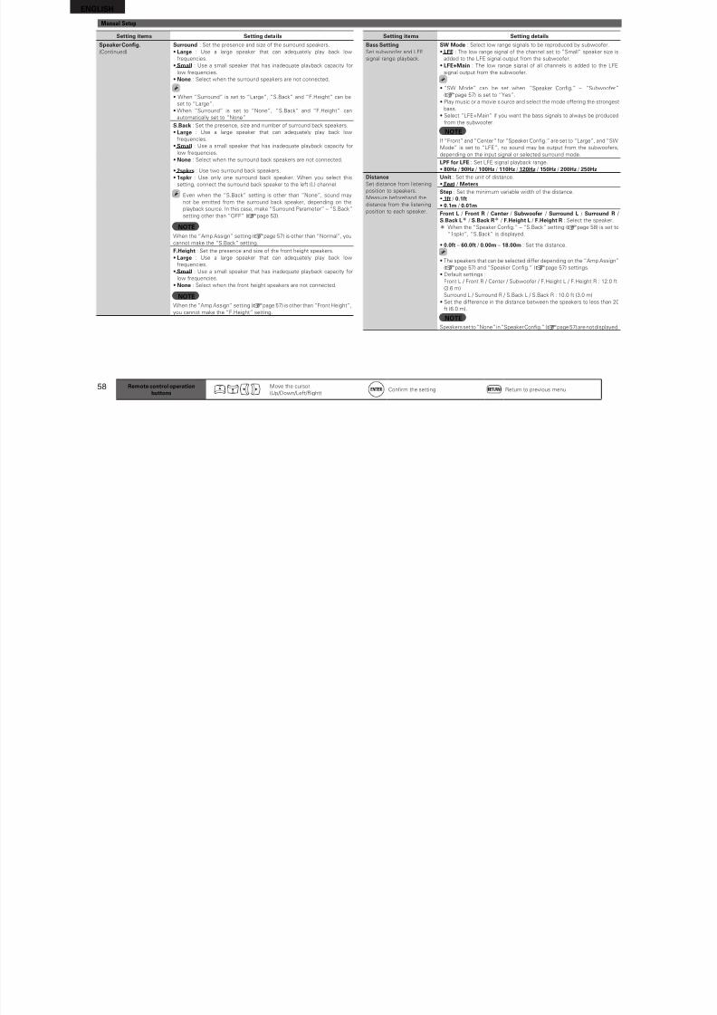
8/7/2019 IBJSC.com | I-WEB.com.vn - 953467670
http://slidepdf.com/reader/full/ibjsccom-i-webcomvn-953467670 61/92
57
B a s
i c v e r s i o n
S i m p l e v e r s i o n
I n f o r m a t i o n
A d v a n c e
d v e r s i o n
Manual SetupSet when changing Audyssey® Auto Setup settings, or when changing the audio, video, displayor other settings.• I you change the speaker settings ater perorming Audyssey Auto Setup, it will not be possible
to set MultEQ®, Dynamic EQ® and Dynamic Volume® (vpage 54, 55).• Can be used without changing the settings. Please set i necessary.
Menu operation
1Press ZONE SELECT to switch the zone mode to “MAIN”.The “MAIN” indicator lights.
2Press AMP to set the remote control unit to amplier operation
mode.
3Press MENU.The menu is displayed on the TV screen.
4Press ui to select the menu to be set or operated.
5Press ENTER or p to enter the setting.
• To return to the previous item, press RETURN.
• Exiting the Menu, press MENU while the menu is displayed.
The menu display disappears.
Items that can be set with the Manual Setup procedure
Amp Assign
Speaker Config.Bass Setting
DistanceChannel LevelCrossover Frequency
Front Speaker Setup
Assign surround back AMP for other use
MANUAL SETUPSPEAKER SETUP
RGB Range
Auto Lip SyncHDMI Audio Out
HDMI Control
Normal
ONAMP
OFF
MANUAL SETUPHDMI SETUP
Use video range from 16 (black) to 235 (white)RETURN Return
2ch Direct/Stereo
Auto Surround ModeEQ Customize
Make various settings for 2ch mode playback
MANUAL SETUPAUDIO SETUP
BassTreble
HPFLevel LchLevel Rch
Channel
0dB0dB
OFF0dB0dB
Stereo
MANUAL SETUPZONE2 SETUP [1/2]
Adjust low frequency range (bass)
RETURN Return
Volume ControlSource Delete
GUIRemote Preset CodesQuick Select Name
Zone RenameTrigger OutRemote ID Setup
MANUAL SETUPOPTION SETUP
Make settings for volume control
Speaker Setup (vpage 57)
ZONE2 Setup (vpage 61) Option Setup (vpage 62)
HDMI Setup (vpage 60) Audio Setup (vpage 60)
p pPerorm when setting the speakers manually or when changing settings made in Audyssey Auto Setup.
• I you change the speaker settings ater perorming Audyssey Auto Setup, it will not be possible to select
MultEQ, Dynamic EQ and Dynamic Volume (vpage 54, 55).
• Manual Setup can be used without changing the settings. Please set i necessary.
Setting items Setting details
Amp AssignSet the speakers connected
to this unit.
Normal : Set when using 7.1-channel (Front/Center/Surround/Surround
Back/Subwooer) speakers.
ZONE2 : Set or connecting the speakers or ZONE2 to the SURR. BACK/
AMP ASSIGN terminals.
Front Height: Set or connecting the ront height speakers to the SURR.
BACK/AMP ASSIGN terminals.
Bi-Amp : Set or connecting a tweeter o a ront speaker to the SURR.
BACK/AMP ASSIGN terminals and a wooer o the ront speaker to the
FRONT terminals.
Front B : Set or connecting the second ront speakers to the SURR.
BACK/AMP ASSIGN terminals. In this case, make settings or “Front
Speaker Setup” (vpage 59).
2CH : Set or 2-channel direct/stereo playback. When “2CH” is set,
connect the second set o ront speakers to the SURR.BACK/AMP
ASSIGN terminals.
Since “Amp Assign” o this unit is set to “ZONE2” by deault, audio is
not output rom the surround back speakers . When using the surround
back speakers with MAIN ZONE, change the “Amp Assi gn” setting to
“Normal”.
Speaker Confg.Select speaker confguration
and size (bass reproduction
capability).
NOTEDo not use the outward
shape o the speaker to
determine selection o a
“Large” or “Small” speaker.
Instead, use the requencies
set in “Crossover
Frequency” (vpage 59) as
the standard or determining
bass reproduction capability.
Front : Set the ront speaker size.
• Large : Use a large speaker that can adequately play back low
requencies.
• Small : Use a small speaker that has inadequate playback capacity or
low requencies.
• When “Subwooer” is set to “No”, “Front” is automatically set to
“Large”.
• When “Front” is set to “Small”, “Center”, “Surround“, “S.Back” and
“F.Height” can not be set to “Large”.
Center : Set the presence and size o the center speaker.
• Large : Use a large speaker that can adequately play back low
requencies.
• Small : Use a small speaker that has inadequate playback capacity or
low requencies.
• None : Select when a center speaker is not connected.
“Large” is not displayed when “Front” is set to “Small”.
Subwooer : Set the presence o a subwooer.
• Yes : Use a subwooer.
• No : Select when a subwooer is not connected.
When “Front” is set to “Small”, “Subwooer” is automatically set to
“Yes”.
Remote control operationbuttons
Move the cursor
(Up/Down/Let/Right)Confrm the setting Return to previous menu
ENGLISHManual Setup
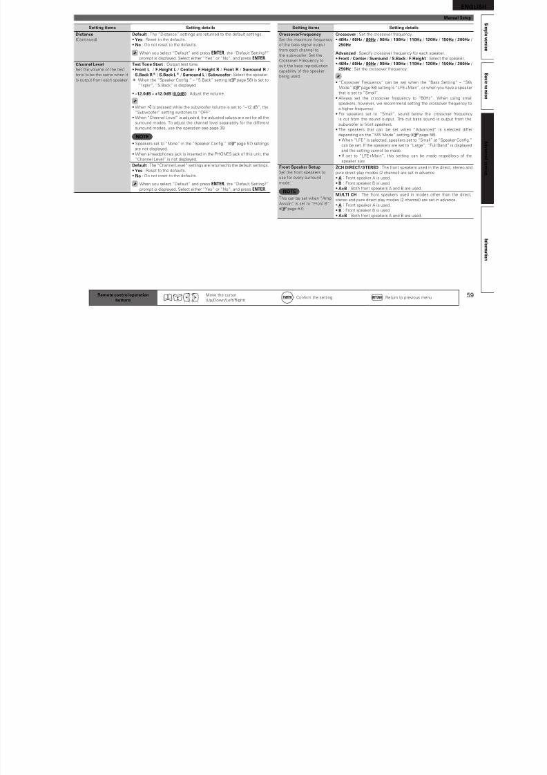
8/7/2019 IBJSC.com | I-WEB.com.vn - 953467670
http://slidepdf.com/reader/full/ibjsccom-i-webcomvn-953467670 62/92
58
Setting items Setting details
Bass SettingSet subwooer and LFE
signal range playback.
SW Mode : Select low range signals to be reproduced by subwooer.
• LFE : The low range signal o the channel set to “Small” speaker size is
added to the LFE signal output rom the subwooer.
• LFE+Main : The low range signal o all channels is added to the LFE
signal output rom the subwooer.
• “SW Mode” can be set when “Speaker Confg.” – “Subwooer”
(vpage 57) is set to “Yes”.
• Play music or a movie source and select the mode oering the strongest
bass.• Select “LFE+Main” i you want the bass signals to always be produced
rom the subwooer.
NOTEI “Front” and “Center” or “Speaker Confg.” are set to “Large”, and “SW
Mode” is set to “LFE”, no sound may be output rom the subwooers,
depending on the input signal or selected surround mode.
LPF or LFE : Set LFE signal playback range.
• 80Hz / 90Hz / 100Hz / 110Hz / 120Hz / 150Hz / 200Hz / 250HzDistanceSet distance rom listening
position to speakers.
Measure beorehand the
distance rom the listening
position to each speaker.
Unit : Set the unit o distance.
• Feet / MetersStep : Set the minimum variable width o the distance.
• 1t / 0.1t• 0.1m / 0.01m
Front L / Front R / Center / Subwooer / Surround L / Surround R /
S.Back Lz / S.Back Rz / F.Height L / F.Height R : Select the speaker.
z When the “Speaker Confg.” – “S.Back” setting (vpage 58) is set to
“1spkr”, “S.Back” is displayed.
• 0.0t – 60.0t / 0.00m – 18.00m : Set the distance.
• The speakers that can be selected dier depending on the “Amp Assign”
(vpage 57) and “Speaker Confg.” (vpage 57) settings.
• Deault settings :
Front L / Front R / Center / Subwooer / F.Height L / F.Height R : 12.0 t
(3.6 m)
Surround L / Surround R / S.Back L / S.Back R : 10.0 t (3.0 m)
• Set the dierence in the distance between the speakers to less than 20
t (6.0 m).
NOTESpeakers set to “None” in “Speaker Confg.” (vpage 57) are not displayed.
Remote control operationbuttons
Move the cursor
(Up/Down/Let/Right)Confrm the setting Return to previous menu
Setting items Setting details
Speaker Confg.(Continued)
Surround : Set the presence and size o the surround speakers.
• Large : Use a large speaker that can adequately play back low
requencies.
• Small : Use a small speaker that has inadequate playback capacity or
low requencies.
• None : Select when the surround speakers are not connected.
• When “Surround” is set to “Large”, “S.Back” and “F.Height” can be
set to “Large”.
• When “Surround” is set to “None”, “S.Back” and “F.Height” canautomatically set to “None”.
S.Back : Set the presence, size and number o surround back speakers.
• Large : Use a large speaker that can adequately play back low
requencies.
• Small : Use a small speaker that has inadequate playback capacity or
low requencies.
• None : Select when the surround back speakers are not connected.
• 2spkrs : Use two surround back speakers.
• 1spkr : Use only one surround back speaker. When you select this
setting, connect the surround back speaker to the let (L) channel.
Even when the “S.Back“ setting is other than “None”, sound may
not be emitted rom the surround back speaker, depending on the
playback source. In this case, make “Surround Parameter” – “S.Back”setting other than “OFF” (vpage 53).
NOTEWhen the “Amp Assign” setting (vpage 57) is other than “Normal”, you
cannot make the “S.Back” setting.
F.Height : Set the presence and size o the ront height speakers.
• Large : Use a large speaker that can adequately play back low
requencies.
• Small : Use a small speaker that has inadequate playback capacity or
low requencies.
• None : Select when the ront height speakers are not connected.
NOTEWhen the “Amp Assign” setting (vpage 57) is other than “Front Height”,
you cannot make the “F.Height” setting.
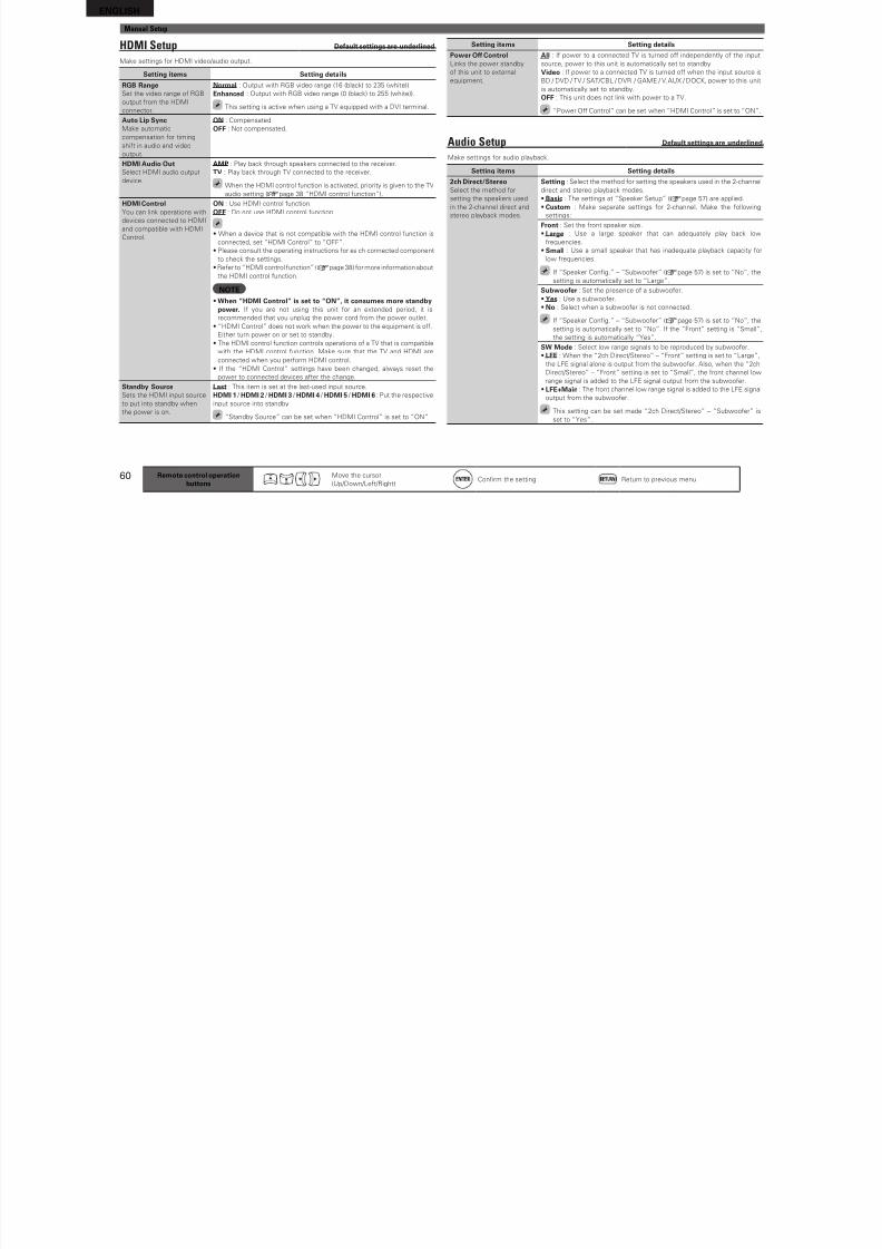
8/7/2019 IBJSC.com | I-WEB.com.vn - 953467670
http://slidepdf.com/reader/full/ibjsccom-i-webcomvn-953467670 63/92
ENGLISHManual Setup
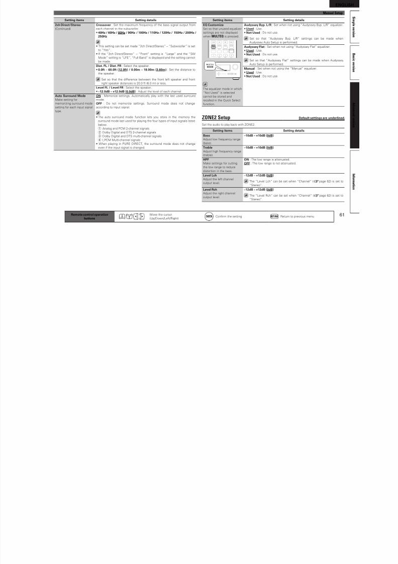
8/7/2019 IBJSC.com | I-WEB.com.vn - 953467670
http://slidepdf.com/reader/full/ibjsccom-i-webcomvn-953467670 64/92
60 Remote control operationbuttons
Move the cursor
(Up/Down/Let/Right)Confrm the setting Return to previous menu
HDMI Setup Deault settings are underlined.
Make settings or HDMI video/audio output.
Setting items Setting details
RGB RangeSet the video range o RGB
output rom the HDMI
connector.
Normal : Output with RGB video range (16 (black) to 235 (white)).
Enhanced : Output with RGB video range (0 (black) to 255 (white)).
This setting is active when using a TV equipped with a DVI terminal.
Auto Lip SyncMake automatic
compensation or timing
shit in audio and video
output.
ON : Compensated.
OFF : Not compensated.
HDMI Audio OutSelect HDMI audio output
device.
AMP : Play back through speakers connected to the receiver.
TV : Play back through TV connected to the receiver.
When the HDMI control unction is activated, priority is given to the TV
audio setting (vpage 38 “HDMI control unction”).
HDMI ControlYou can link operations with
devices connected to HDMI
and compatible with HDMI
Control.
ON : Use HDMI control unction.
OFF : Do not use HDMI control unction.
• When a device that is not compatible with the HDMI control unction is
connected, set “HDMI Control” to “OFF”.
• Please consult the operating instructions or each connected component
to check the settings.• Reer to “HDMI control unction” (vpage 38) or more inormation about
the HDMI control unction.
NOTE• When “HDMI Control” is set to “ON”, it consumes more standby
power. I you are not using this unit or an extended period, it is
recommended that you unplug the power cord rom the power outlet.
• “HDMI Control” does not work when the power to the equipment is o.
Either turn power on or set to standby.
• The HDMI control unction controls operations o a TV that is compatible
with the HDMI control unction. Make sure that the TV and HDMI are
connected when you perorm HDMI control.
• I the “HDMI Control” settings have been changed, always reset the
power to connected devices ater the change.
Standby SourceSets the HDMI input source
to put into standby when
the power is on.
Last : This item is set at the last-used input source.
HDMI 1 / HDMI 2 / HDMI 3 / HDMI 4 / HDMI 5 / HDMI 6 : Put the respective
input source into standby.
“Standby Source” can be set when “HDMI Control” is set to “ON”.
Setting items Setting details
Power O ControlLinks the power standby
o this unit to external
equipment.
All : I power to a connected TV is turned o independently o the input
source, power to this unit is automatically set to standby.
Video : I power to a connected TV is turned o when the input source is
BD / DVD / TV / SAT/CBL / DVR / GAME / V.AUX / DOCK, power to this unit
is automatically set to standby.
OFF : This unit does not link with power to a TV.
“Power O Control” can be set when “HDMI Control” is set to “ON”.
Audio Setup Deault settings are underlined.
Make settings or audio playback.
Setting items Setting details
2ch Direct/StereoSelect the method or
setting the speakers used
in the 2-channel direct and
stereo playback modes.
Setting : Select the method or setting the speakers used in the 2-channel
direct and stereo playback modes.
• Basic : The settings at “Speaker Setup” (vpage 57) are applied.
• Custom : Make separate settings or 2-channel. Make the ollowing
settings:
Front : Set the ront speaker size.
• Large : Use a large speaker that can adequately play back low
requencies.
• Small : Use a small speaker that has inadequate playback capacity or
low requencies.
I “Speaker Confg.” – “Subwooer” (vpage 57) is set to “No”, the
setting is automatically set to “Large”.
Subwooer : Set the presence o a subwooer.
• Yes : Use a subwooer.
• No : Select when a subwooer is not connected.
I “Speaker Confg.” – “Subwooer” (vpage 57) is set to “No”, the
setting is automatically set to “No”. I the “Front” setting is “Small”,
the setting is automatically “Yes”.
SW Mode : Select low range signals to be reproduced by subwooer.
• LFE : When the “2ch Direct/Stereo” – “Front” setting is set to “Large”,
the LFE signal alone is output rom the subwooer. Also, when the “2ch
Direct/Stereo” – “Front” setting is set to “Small”, the ront channel low
range signal is added to the LFE signal output rom the subwooer.• LFE+Main : The ront channel low range signal is added to the LFE signal
output rom the subwooer.
This setting can be set made “2ch Direct/Stereo” – “Subwooer” is
set to “Yes”.
ENGLISH
S Manual Setup
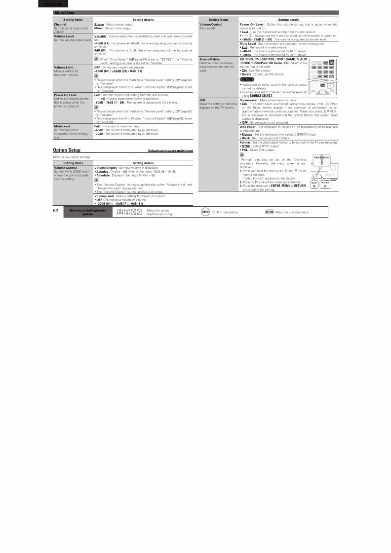
8/7/2019 IBJSC.com | I-WEB.com.vn - 953467670
http://slidepdf.com/reader/full/ibjsccom-i-webcomvn-953467670 65/92
61
B a s
i c v e r s i o n
Si m p l e v e r s i o n
I n f o r m a t i o n
A d v a n c e d v e r s i o n
Setting items Setting details
EQ CustomizeSet so that unused equalizer
settings are not displayed
when MULTEQ is pressed.
The equalizer mode in which
“Not Used” is selected
cannot be stored and
recalled in the Quick Select
unction.
Audyssey Byp. L/R : Set when not using “Audyssey Byp. L/R” equalizer.
• Used : Use.
• Not Used : Do not use.
Set so that “Audyssey Byp. L/R” settings can be made when
Audyssey Auto Setup is perormed.
Audyssey Flat : Set when not using “Audyssey Flat” equalizer.
• Used : Use.
• Not Used : Do not use.
Set so that “Audyssey Flat” settings can be made when AudysseyAuto Setup is perormed.
Manual : Set when not using the “Manual” equalizer.
• Used : Use.
• Not Used : Do not use.
ZONE2 Setup Deault settings are underlined.
Set the audio to play back with ZONE2.
Setting items Setting details
BassAdjust low requency range
(bass).
–10dB – +10dB (0dB)
TrebleAdjust high requency range
(treble).
–10dB – +10dB (0dB)
HPFMake settings or cutting
the low range to reduce
distortion in the bass.
ON : The low range is attenuated.
OFF : The low range is not attenuated.
Level LchAdjust the let channel
output level.
–12dB – +12dB (0dB)
The “Level Lch” can be set when “Channel“ (vpage 62) is set to
“Stereo“.
Level RchAdjust the right channel
output level.
–12dB – +12dB (0dB)
The “Level Rch” can be set when “Channel“ (vpage 62) is set to
“Stereo“.
Remote control operationbuttons
Move the cursor
(Up/Down/Let/Right)Confrm the setting Return to previous menu
Setting items Setting details
2ch Direct/Stereo(Continued)
Crossover : Set the maximum requency o the bass signal output rom
each channel to the subwooer.
• 40Hz / 60Hz / 80Hz / 90Hz / 100Hz / 110Hz / 120Hz / 150Hz / 200Hz /250Hz
• This setting can be set made “2ch Direct/Stereo” – “Subwooer” is set
to “Yes”.
• I the “2ch Direct/Stereo” – “Front” setting is “Large” and the “SW
Mode” setting is “LFE”, “Full Band” is displayed and the setting cannot
be made.
Dist. FL / Dist. FR : Select the speaker.
• 0.0t – 60.0t (12.0t) / 0.00m – 18.00m (3.60m) : Set the distance to
the speaker.
Set so that the dierence between the ront let speaker and ront
right speaker distances is 20.0 t (6.0 m) or less.
Level FL / Level FR : Select the speaker.
• –12.0dB – +12.0dB (0.0dB) : Adjust the level o each channel.
Auto Surround ModeMake setting or
memorizing surround mode
setting or each input signal
type.
ON : Memorize settings. Automatically play with the last used surround
mode.
OFF : Do not memorize settings. Surround mode does not change
according to input signal.
• The auto surround mode unction lets you store in the memory thesurround mode last used or playing the our types o input signals listed
below.
q Analog and PCM 2-channel signals
w Dolby Digital and DTS 2-channel signals
e Dolby Digital and DTS multi-channel signals
r LPCM Multi-channel signals
• When playing in PURE DIRECT, the surround mode does not change
even i the input signal is changed.
ENGLISHManual Setup
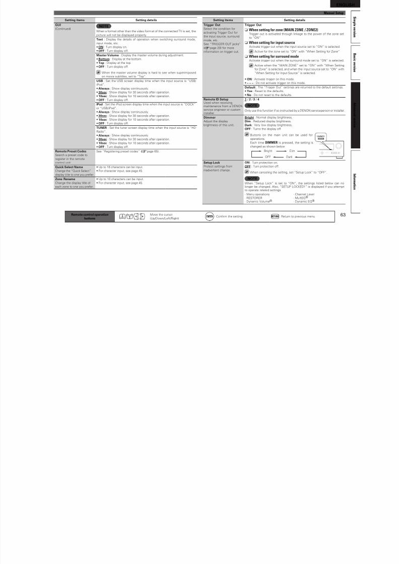
8/7/2019 IBJSC.com | I-WEB.com.vn - 953467670
http://slidepdf.com/reader/full/ibjsccom-i-webcomvn-953467670 66/92
62 Remote control operationbuttons
Move the cursor
(Up/Down/Let/Right)Confrm the setting Return to previous menu
Setting items Setting details
Volume Control(Continued)
Power On Level : Defne the volume setting that is active when the
power is turned on.
• Last : Use the memorized setting rom the last session.
• – – – (0) : Always use the muting on condition when power is turned on.
• –80dB – 18dB (1 – 99) : The volume is adjusted to the set level.
Mute Level : Set the amount o attenuation when muting is on.
• Full : The sound is muted entirely.
• –40dB : The sound is attenuated by 40 dB down.
• –20dB : The sound is attenuated by 20 dB down.
Source DeleteRemove rom the display
input sources that are not
used.
BD / DVD / TV / SAT/CBL / DVR / GAME / V.AUX / DOCK / USB/iPod / HD Radio / CD : Select input
source that is not used.
• ON : Use this source.
• Delete : Do not use this source.
NOTE• Input sources being used in the var ious zones
cannot be deleted.
• Input sources set to “Delete” cannot be selected
using SOURCE SELECT.
GUIMake the settings related to
displays on the TV screen.
Screensaver : Make screensaver settings.
• ON : The screen saver is activated during menu display, iPod, USB/iPod
or HD Radio screen display i no operation is perormed or an
approximately 3-minute continuous period. When you press uio p,
the screensaver is cancelled and the screen beore that screen saverstarted is displayed.
• OFF : Screensaver is not activated.
Wall Paper : Set wallpaper to display in the background when playback
is stopped, etc.
• Picture : Set the background to a picture (DENON logo).
• Black : Set the background to black.
Format : Set the video signal ormat to be output or the TV you are using.
• NTSC : Select NTSC output.
• PAL : Select PAL output.
“Format” can also be set by the ollowing
procedure. However, the menu screen is not
displayed.
1. Press and hold the main unit’s p and i or atleast 3 seconds.
“Video Format” appears on the display.
2. Press o p and set the video signal ormat.
3. Press the main unit’s ENTER, MENU or RETURN
to complete the setting.
Setting items Setting details
ChannelSet the signal output rom
ZONE2.
Stereo : Select stereo output.
Mono : Select mono output.
Volume LevelSet the volume output level.
Variable : Volume adjustment is enabled by main unit and remote control
unit.
–40dB (41) : Fix volume at –40 dB. Set when adjusting volume by external
amplifer.
0dB (81) : Fix volume at 0 dB. Set when adjusting volume by external
amplifer.
When “Amp Assign” (vpage 57) is set to “ZONE2”, the “VolumeLevel” setting is automatically set to “Variable”.
Volume LimitMake a setting or
maximum volume.
OFF : Do not set a maximum volume.
–20dB (61) / –10dB (71) / 0dB (81)
• This can be set when the mul ti-zone “Volume Level” setting (vpage 62)
is “Variable”.
• This is displayed rom 0 to 99 when “Volume Display” (vpage 62) is set
to “Absolute”.
Power On LevelDefne the volume setting
that is active when the
power is turned on.
Last : Use the memorized setting rom the last session.
– – – (0) : Always mute when power is turned on.
–80dB – 18dB (1 – 99) : The volume is adjusted to the set level.
• This can be set when the mul ti-zone “Volume Level” setting (vpage 62)
is “Variable”.• This is displayed rom 0 to 99 when “Volume Display” (vpage 62) is set
to “Absolute”.
Mute LevelSet the amount o
attenuation when muting
is on.
Full : The sound is muted entirely.
–40dB : The sound is attenuated by 40 dB down.
–20dB : The sound is attenuated by 20 dB down.
Option Setup Deault settings are underlined.
Make various other settings.
Setting items Setting details
Volume ControlSet the MAIN ZONE (room
where the unit is located)
volume setting.
Volume Display : Set how volume is displayed.
• Relative : Display ---dB (Min), in the range –80.5 dB – 18 dB.
• Absolute : Display in the range 0 (Min) – 99.
• The “Volume Display” setting is applied also to the “Volume Limit” and
“Power On Level” display method.
• The “Volume Display” setting applies to all zones.
Volume Limit : Make a setting or maximum volume.
• OFF : Do not set a maximum volume.
• –20dB (61) / –10dB (71) / 0dB (81)
ENGLISH
S Manual Setup
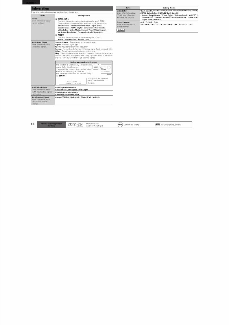
8/7/2019 IBJSC.com | I-WEB.com.vn - 953467670
http://slidepdf.com/reader/full/ibjsccom-i-webcomvn-953467670 67/92
63
B a s i c v e r s i o n
Si m p l e v e r s i o n
I n f o r m a t i o n
A d v a n c e d v e r s i o n
Setting items Setting details
GUI(Continued)
NOTEWhen a ormat other than the video ormat o the connected TV is set, the
picture will not be displayed properly.
Text : Display the details o operation when switching surround mode,
input mode, etc.
• ON : Turn display on.
• OFF : Turn display o.
Master Volume : Display the master volume during adjustment.
• Bottom : Display at the bottom.
• Top : Display at the top.
• OFF : Turn display o.
When the master volume display is hard to see when superimposed
on movie subtitles, set to “Top”.
USB : Set the USB screen display time when the input source is “USB/
iPod”.
• Always : Show display continuously.
• 30sec : Show display or 30 seconds ater operation.
• 10sec : Show display or 10 seconds ater operation.
• OFF : Turn display o.
iPod : Set the iPod screen display time when the input source is “DOCK”
or “USB/iPod”.
• Always : Show display continuously.
• 30sec : Show display or 30 seconds ater operation.• 10sec : Show display or 10 seconds ater operation.
• OFF : Turn display o.
TUNER : Set the tuner screen display time when the input source is “HD
Radio”.
• Always : Show display continuously.
• 30sec : Show display or 30 seconds ater operation.
• 10sec : Show display or 10 seconds ater operation.
• OFF : Turn display o.
Remote Preset CodesSearch a preset code to
register in the remote
control unit.
See “Registering preset codes” (vpage 65).
Quick Select NameChange the “Quick Select”
display title to one you preer.
• Up to 16 characters can be input.
• For character input, see page 45.
Zone RenameChange the display title o
each zone to one you preer.
• Up to 10 characters can be input.
• For character input, see page 45.
Setting items Setting details
Trigger OutSelect the condition or
activating Trigger Out or
the input source, surround
mode, etc.
See “TRIGGER OUT jacks”
(vpage 20) or more
inormation on trigger out.
Trigger Out
n When setting for zone (MAIN ZONE / ZONE2)Trigger out is activated through linkage to the power o the zone set
to “ON”.
n When setting for input sourceActivate trigger out when the input source set to “ON” is selected.
Active or the zone set to “ON” with “When Setting or Zone”.
n When setting for surround mode
Activate trigger out when the surround mode set to “ON” is selected.Active when the “MAIN ZONE” set to “ON” with “When Setting
or Zone” is selected, and when the input source set to “ON” with
“When Setting or Input Source” is selected.
• ON : Activate trigger on this mode.
• – – – : Do not activate trigger on this mode.
Deault : The “Trigger Out” settings are returned to the deault settings.
• Yes : Reset to the deaults.
• No : Do not reset to the deaults.
Remote ID SetupUsed when receivingmaintenance rom a DENONservice engineer or custominstaller.
1 / 2 / 3 / 4
NOTEOnly use this unction i so instructed by a DENON serviceperson or installer.
DimmerAdjust the display
brightness o this unit.
Bright : Normal display brightness.Dim : Reduced display brightness.
Dark : Very low display brightness.
OFF : Turns the display o.
Buttons on the main unit can be used or
operations.
Each time DIMMER is pressed, the setting is
changed as shown below.
Bright Dim
DarkOFF
Setup LockProtect settings rom
inadvertent change.
ON : Turn protection on.
OFF : Turn protection o.
When canceling the setting, set “Setup Lock” to “OFF”.
NOTEWhen “Setup Lock” is set to “ON”, the settings listed below can nolonger be changed. Also, “SETUP LOCKED!” is displayed i you attemptto operate related settings.
· Menu operations · Channel Level
· RESTORER · MultEQ®
· Dynamic Volume® · Dynamic EQ®
Remote control operationbuttons
Move the cursor
(Up/Down/Let/Right)Confrm the setting Return to previous menu
ENGLISH
Information Items Setting details
Quick Select Quick Select 1 / QuickSelect2 / Quick Select 3 / ZONE2QuickSelect1 /
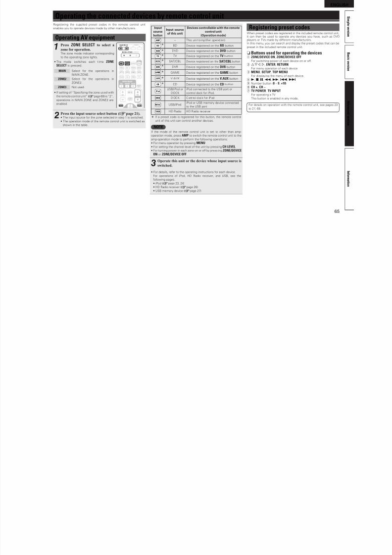
8/7/2019 IBJSC.com | I-WEB.com.vn - 953467670
http://slidepdf.com/reader/full/ibjsccom-i-webcomvn-953467670 68/92
64
Show inormation about receiver settings, input signals, etc.
Items Setting details
StatusShow inormation about
current settings.
n MAIN ZONEThis item shows inormation about settings or MAIN ZONE.
The inormation displayed diers according to the input source.
Select Source / Name / Surround Mode / Input Mode /
Decode Mode / HDMI / Digital / Component / Rec Select /
Video Select / Video Mode / Content Type / Video Convert /
i/p Scaler / Resolution / Progressive Mode / Aspect etc.
n ZONE2This item shows inormation about settings or ZONE2.
Power / Select Source / Volume Level
Audio Input SignalShow inormation about
audio input signals.
Surround Mode : The currently set surround mode.
Signal : The input signal type.
s : The input signal’s sampling requency.
Format : The number o channels in the input signal (ront, surround, LFE).
Oset : The dialogue normalization correction value.
Flag : This is displayed when inputting signals including a surround back
channel. “MATRIX” is displayed with Dolby Digital EX and DTS-ES Matrix
signals, “DISCRETE” with DTS-ES Discrete signals.
Dialogue normalization unctionThis unction is automatically activated when
playing Dolby Digital sources.It automatically corrects the standard signal
level or individual program sources.
The correction value can be checked using
the STATUS.
The fgure is the corrected
value. This cannot be
changed.
HDMI InormationShow inormation about
HDMI input/output signals
and monitor.
HDMI Signal Inormation• Resolution / Color Space / Pixel Depth
HDMI Monitor Inormation• Interace / Supported resol.
Auto Surround Mode
Show inormation aboutauto surround mode
settings.
Analog / PCM 2ch / Digital 2ch / Digital 5.1ch / Multi ch
Quick SelectShow inormation about
“Quick select unction”
(vpage 40) settings.
Quick Select 1 / Quick Select 2 / Quick Select 3 / ZONE2 Quick Select 1 /
ZONE2 Quick Select 2 / ZONE2 Quick Select 3• Name / Select Source / Video Select / Volume Level / MultEQ® /
Dynamic EQ® / Dynamic Volume® / Analog/PCM 2ch / Digital 2ch /
Digital 5.1ch / Multi Ch
Preset ChannelShow inormation about
preset channels.
HD Radio
A / B / C / D / E / F / GA1 – A8 / B1 – B8 / C1 – C8 / D1 – D8 / E1 – E8 / F1 – F8 / G1 – G8
Remote control operationbuttons
Move the cursor
(Up/Down/Let/Right)Confrm the setting Return to previous menu
ENGLISH
S i Operating the connected devices by remote control unit
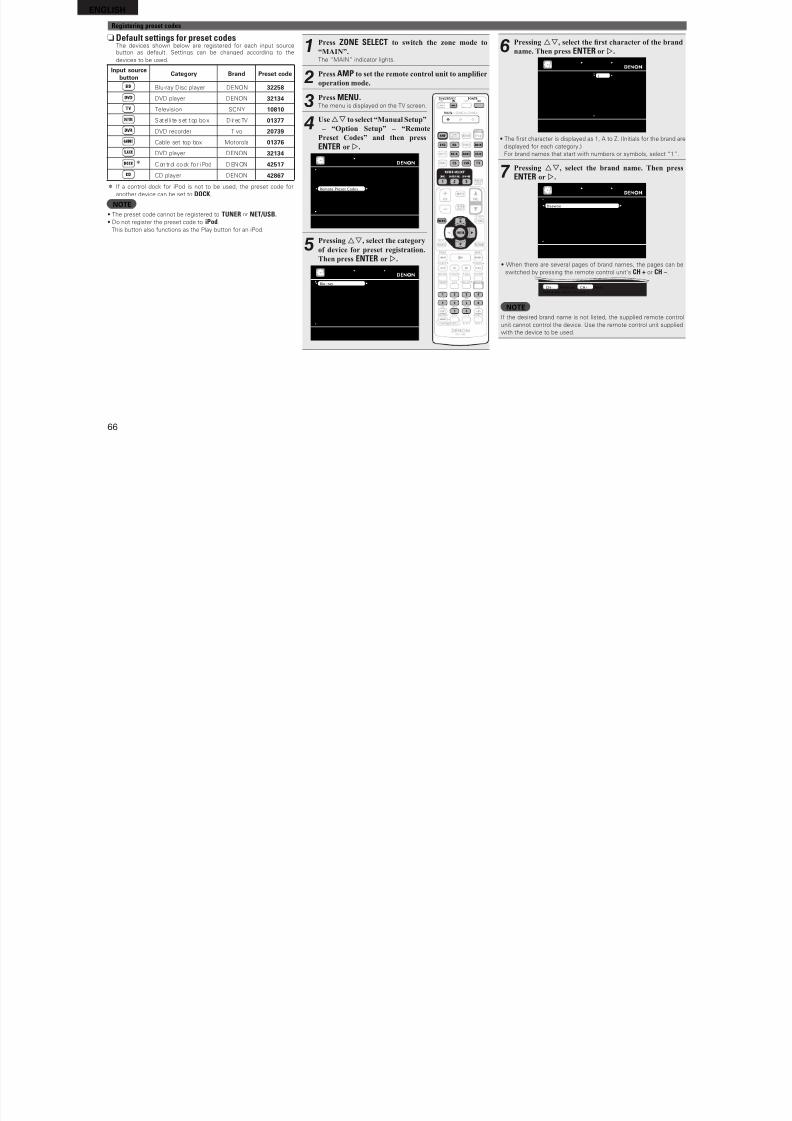
8/7/2019 IBJSC.com | I-WEB.com.vn - 953467670
http://slidepdf.com/reader/full/ibjsccom-i-webcomvn-953467670 69/92
65
B a s i c v e r s i o n
im p l e v e r s i o n
I n f o r m a t i o n
A d v a n c e d v e r s i o n
Op g byRegistering the supplied preset codes in the remote control unit
enables you to operate devices made by other manuacturers.
Operating AV equipment
1Press ZONE SELECT to select a
zone for operation.The zone mode indicator corresponding
to the operating zone lights.
• The mode switches each t ime ZONESELECT is pressed.
MAIN Select or the operations in
MAIN ZONE.
ZONE2 Select or the operations in
ZONE2.
ZONE3 Not used.
• I setting o “Speciying the zone used with
the remote control unit” (vpage 69) is “2”,
operations in MAIN ZONE and ZONE2 are
enabled.
2Press the input source select button
(vpage 21).
• The input source or the zone selected in step 1 is switched.
• The operation mode o the remote control unit is switched as
shown in the table.
Inputsourcebutton
Input sourceo this unit
Devices controllable with the remotecontrol unit
(Operation mode)
– This uni t (ampl ifer operat ion)
z BD Device registered on the BD button
z DVD Device registered on the DVD button
z TV Device registered on the TV button
z SAT/CBL Device registered on the SAT/CBL button
z DVR Device registered on the DVR button
z GAME Device registered on the GAME button
z V.AUX Device registered on the V.AUX button
z CD Device registered on the CD button
USB/iPod or
DOCK
iPod connected to the USB port or
control dock or iPod.
DOCK Contro l dock or iPod
USB/iPodiPod or USB memory device connected
to the USB port
HD Radio HD Radio receiver
z I a preset code is registered or this button, the remote control
unit o this unit can control another devices.
NOTEI the mode o the remote control unit is set to other than amp-
operation mode, press AMP to switch the remote control unit to the
amp-operation mode to perorm the ollowing operations:
• For menu operation by pressing MENU• For setting the channel level o the unit by pressing CH LEVEL• For turning power in each zone on or o by press ing ZONE/DEVICE
ON or ZONE/DEVICE OFF.
3Operate this unit or the device whose input source is
switched.
• For details, reer to the operating instructions or each device.
For operations o iPod, HD Radio receiver, and USB, see the
ollowing pages.
• iPod (vpage 23, 24)
• HD Radio receiver (vpage 26)
• USB memory device (vpage 27)
Registering preset codesWhen preset codes are registered in the included remote control unit,it can then be used to operate any devices you have, such as DVDplayers or TVs made by dierent manuacturers.In this menu, you can search and display the preset codes that can be
preset in the included remote control unit.
n Buttons used for operating the devicesq ZONE/DEVICE ON, ZONE/DEVICE OFF
For switching power o each device on or o.w uio p, ENTER, RETURN
For menu operation o each device.
e MENU, SETUP, TOP MENUFor displaying the menu o each device.
r 1, 2, 3, 6, 7, 8, 9t Number button (0 – 9, +10)
y CH +, CH –u TV POWER, TV INPUT
For operating a TV
This button is enabled in any mode.
For details on operation with the remote control unit, see pages 23
to 27, 68.
ENGLISHRegistering preset codes
nDefault settings for preset codes
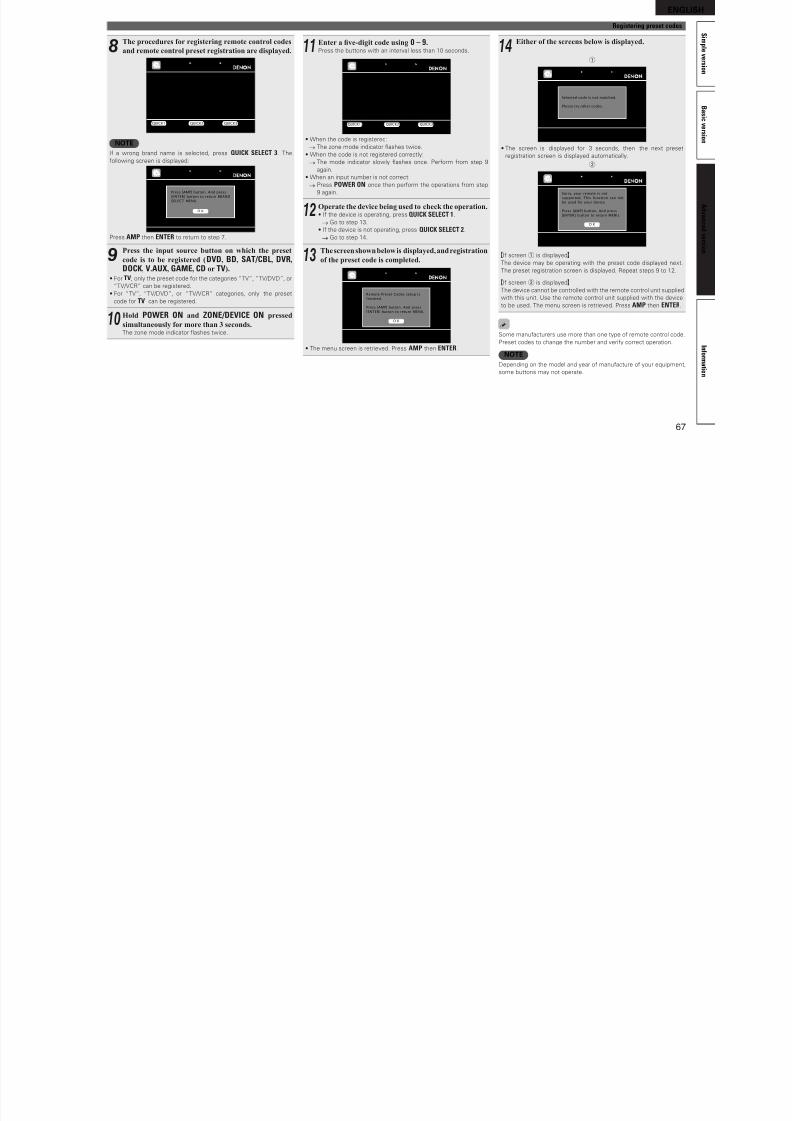
8/7/2019 IBJSC.com | I-WEB.com.vn - 953467670
http://slidepdf.com/reader/full/ibjsccom-i-webcomvn-953467670 70/92
66
nDefault settings for preset codesThe devices shown below are registered or each input sourcebutton as deault. Settings can be changed according to the
devices to be used.
Input sourcebutton
Category Brand Preset code
Blu-ray Disc player DENON 32258
DVD player DENON 32134
Television SONY 10810
Satel li te set top box DirecTV 01377DVD recorder Tivo 20739
Cable set top box Motorola 01376
DVD player DENON 32134z Control dock o r iPod DENON 42517
CD player DENON 42867
z I a control dock or iPod is not to be used, the preset code or
another device can be set to DOCK.
NOTE• The preset code cannot be registered to TUNER or NET/USB.• Do not register the preset code to iPod.
This button also unctions as the Play button or an iPod.
1Press ZONE SELECT to switch the zone mode to
“MAIN”.The “MAIN” indicator lights.
2Press AMP to set the remote control unit to amplier
operation mode.
3Press MENU.The menu is displayed on the TV screen.
4Useui to select “Manual Setup” – “Option Setup” – “Remote
Preset Codes” and then press
ENTER or p.
Volume Control
Source Delete
GUI
Remote Preset Codes
Quick Select Name
Zone Rename
Trigger Out
Remote ID Setup
MANUAL SETUP
OPTION SETUP
Search preset codes to register in the RC
5Pressing ui, select the category
of device for preset registration.
Then press ENTER or p.
Blu-ray
CD
CD Recorder
CABLE
CABLE/PVR
DVD
DVD Recorder
HD-DVD
IPTV STB
PVR
D
I
J
L
M
O
P
S
V
Y
MANUAL SETUP OPTION SETUP
REMOTE PRESET CODES
Select the device category
6Pressing ui, select the rst character of the brand
name. Then press ENTER or p.
Blu-ray
CD
CD Recorder
CABLE
CABLE/PVR
DVD
DVD Recorder
HD-DVD
IPTV STB
PVR
1
A
B
C
D
E
F
G
H
I
MANUAL SETUP OPTION SETUP
REMOTE PRESET CODES
Select first letter of device brand
• The frst character is displayed as 1, A to Z. (Initials or the brand are
displayed or each category.)
For brand names that start with numbers or symbols, select “1”.
7Pressing ui, select the brand name. Then press
ENTER or p.
Daewoo
Dantax
Denon
Disney
DSE
Durabrand
- DVD -
MANUAL SETUP OPTION SETUP
REMOTE PRESET CODES [1/7]
Select the device brand
• When there are several pages o brand names, the pages can be
switched by pressing the remote control unit’s CH + or CH –.
Select the device brand
CH- Previous CH+ Next
NOTEI the desired brand name is not listed, the supplied remote control
unit cannot control the device. Use the remote control unit supplied
with the device to be used.
ENGLISH
S i
Registering preset codes
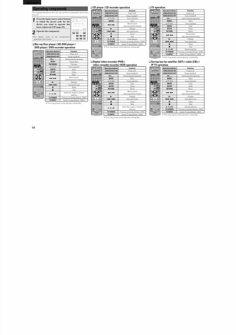
8/7/2019 IBJSC.com | I-WEB.com.vn - 953467670
http://slidepdf.com/reader/full/ibjsccom-i-webcomvn-953467670 71/92
67
B a s i c v e r s i o n
m p l e v e r s i o n
I n f o r m a t i o n
A d v a n c e d v e r s i o n
8The procedures for registering remote control codes
and remote control preset registration are displayed.
CategoryBrandCode [ 1/ 3]Setup Remote1. Press [INPUT SOURCE] button.2. Press and hold 3sec. both [POWER ON]
[DEVICE ON] button.3. Input Code with [0-9] button.4. Press any key to check device.
(e.g. [DEVICE ON])
: DVD: Denon: 30490
MANUAL SETUP OPTION SETUPREMOTE PRESET CODES
Press QUICK 1 if device works, QUICK 2 if notQUICK1 OK QUICK2 NG QUICK3 Return
NOTEI a wrong brand name is selected, press QUICK SELECT 3. The
ollowing screen is displayed:
Press [AMP] button. And press
[ENTER] button to return BRAND
SELECT MENU.
MANUAL SETUP OPTION SETUP
REMOTE PRESET CODES
O K
Press AMP then ENTER to return to step 7.
9Press the input source button on which the preset
code is to be registered (DVD, BD, SAT/CBL, DVR,
DOCK, V.AUX, GAME, CD or TV).
• For TV, only the preset code or the categories “TV”, “TV/DVD”, or
“TV/VCR” can be registered.
• For “TV”, “TV/DVD”, or “TV/VCR” categories, only the preset
code or TV can be registered.
10Hold POWER ON and ZONE/DEVICE ON pressed
simultaneously for more than 3 seconds.The zone mode indicator ashes twice.
11Enter a ve-digit code using 0 – 9.Press the buttons with an interval less than 10 seconds.
CategoryBrandCode [ 1/ 3]Setup Remote1. Press [INPUT SOURCE] button.2. Press and hold 3sec. both [POWER ON]
[DEVICE ON] button.3. Input Code with [0-9] button.4. Press any key to check device.
(e.g. [DEVICE ON])
: DVD: Denon: 30490
MANUAL SETUP OPTION SETUPREMOTE PRESET CODES
Press QUICK 1 if device works, QUICK 2 if notQUICK1 OK QUICK2 NG QUICK3 Return
• When the code is registered: The zone mode indicator ashes twice.
• When the code is not registered correctly:
The mode indicator slowly ashes once. Perorm rom step 9
again.
• When an input number is not correct:
Press POWER ON once then perorm the operations rom step
9 again.
12Operate the device being used to check the operation.• I the device is operating, press QUICK SELECT 1.
Go to step 13.
• I the device is not operating, press QUICK SELECT 2.
Go to step 14.
13The screen shown below is displayed, and registration
of the preset code is completed.
Remote Preset Codes setup is
finished.
Press [AMP] button. And press
[ENTER] button to return MENU.
MANUAL SETUP OPTION SETUP
REMOTE PRESET CODES
O K
• The menu screen is retrieved. Press AMP then ENTER.
14Either of the screens below is displayed.
q
Selected code is not matched.
Plesse try other codes.
MANUAL SETUP OPTION SETUP
REMOTE PRESET CODES
• The screen is displayed or 3 seconds, then the next preset
registration screen is displayed automatically.
w
Sorry, your remote is not
supported. This function can not
be used for your device
Press [AMP] button. And press
[ENTER] button to return MENU.
MANUAL SETUP OPTION SETUP
REMOTE PRESET CODES
O K
GI screen q is displayedH
The device may be operating with the preset code displayed next.
The preset registration screen is displayed. Repeat steps 9 to 12.
GI screen w is displayedH
The device cannot be controlled with the remote control unit supplied
with this unit. Use the remote control unit supplied with the device
to be used. The menu screen is retrieved. Press AMP then ENTER.
Some manuacturers use more than one type o remote control code.
Preset codes to change the number and veriy correct operation.
NOTEDepending on the model and year o manuacture o your equipment,
some buttons may not operate.
ENGLISH n CD player / CD recorder operation
Operation buttons Function
n TV operationOperation buttons Function
Operating components
8/7/2019 IBJSC.com | I-WEB.com.vn - 953467670
http://slidepdf.com/reader/full/ibjsccom-i-webcomvn-953467670 72/92
68
p
ZONE/DEVICE ON Power onz
ZONE/DEVICE OFF Power standbyz
uio p Cursor operation
ENTER Enter
6 7Manual search
(fast-reverse/fast-forward)
1 Playback
8 9 Auto search (cue)
3 Pause
2 Stop0 – 9, +10 Track selection
TV POWER TV power on/standby (Default : SONY)
TV INPUT Switch TV input (Default : SONY)
zThis may power some devices on/standby.
n Digital video recorder (PVR) / video cassette recorder (VCR) operation
Operation buttons Function
ZONE/DEVICE ON Power onz
ZONE/DEVICE OFF Power standbyz
CH +, – Switch channels (up/down)
MENU Menu
uio p Cursor operation
ENTER Enter
SETUP Setup
RETURN Return
6 7Manual search
(fast-reverse/fast-forward)
1 Playback
8 9 Auto search (cue)
3 Pause
2 Stop
0 – 9, +10Select title, chapter or channel
selection
TV POWER TV power on/standby (Default : SONY)
TV INPUT Switch TV input (Default : SONY)
zThis may power some devices on/standby.
p
ZONE/DEVICE ON Power onz
ZONE/DEVICE OFF Power standbyz
CH +, – Switch channels (up/down)
MENU Menu
uio p Cursor operation
ENTER Enter
SETUP Setup
RETURN Return
6 7Manual search
(fast-reverse/fast-forward)1 Playback
8 9 Auto search (cue)
3 Pause
2 Stop
0 – 9, +10 Channel selection
TV POWER TV power on/standby (Default : SONY)
TV INPUT Switch TV input (Default : SONY)
zThis may power some devices on/standby.
n Set top box for satellite (SAT) / cable (CBL) / IP TV operation
Operation buttons Function
ZONE/DEVICE ON Power onz
ZONE/DEVICE OFF Power standbyz
CH +, – Switch channels (up/down)
MENU Menu
uio p Cursor operation
ENTER Enter
SETUP Guide
RETURN Return
6 7Manual search
(fast-reverse/fast-forward)
1 Playback
8 9 Auto search (cue)
3 Pause
2 Stop
0 – 9, +10 Channel selection
TV POWER TV power on/standby (Default : SONY)
TV INPUT Switch TV input (Default : SONY)
zThis may power some devices on/standby.
The supplied remote control unit can control a component other than
this unit.
1Press the input source select button
to which the preset code for the
device you want to operate has
been registered (vpage 65).
2Operate the component.
• For details, reer to the component’soperating instructions.
nBlu-ray Disc player / HD-DVD player / DVD player / DVD recorder operation
Operation buttons Function
ZONE/DEVICE ON Power onz
ZONE/DEVICE OFF Power standbyz
CH +, – Switch channels (up/down)
MENU (Popup) Menu
TOP MENU Top menu
uio p Cursor operation
ENTER EnterSETUP Setup
RETURN Return
6 7Manual search
(fast-reverse/fast-forward)
1 Playback
8 9 Auto search (cue)
3 Pause
2 Stop
0 – 9, +10Select title, chapter or channel
selection
TV POWER TV power on/standby (Default : SONY)
TV INPUT Switch TV input (Default : SONY)
zThis may power some devices on/standby.
Information
ENGLISH
S i m
Specifying the zone used with thet t l it
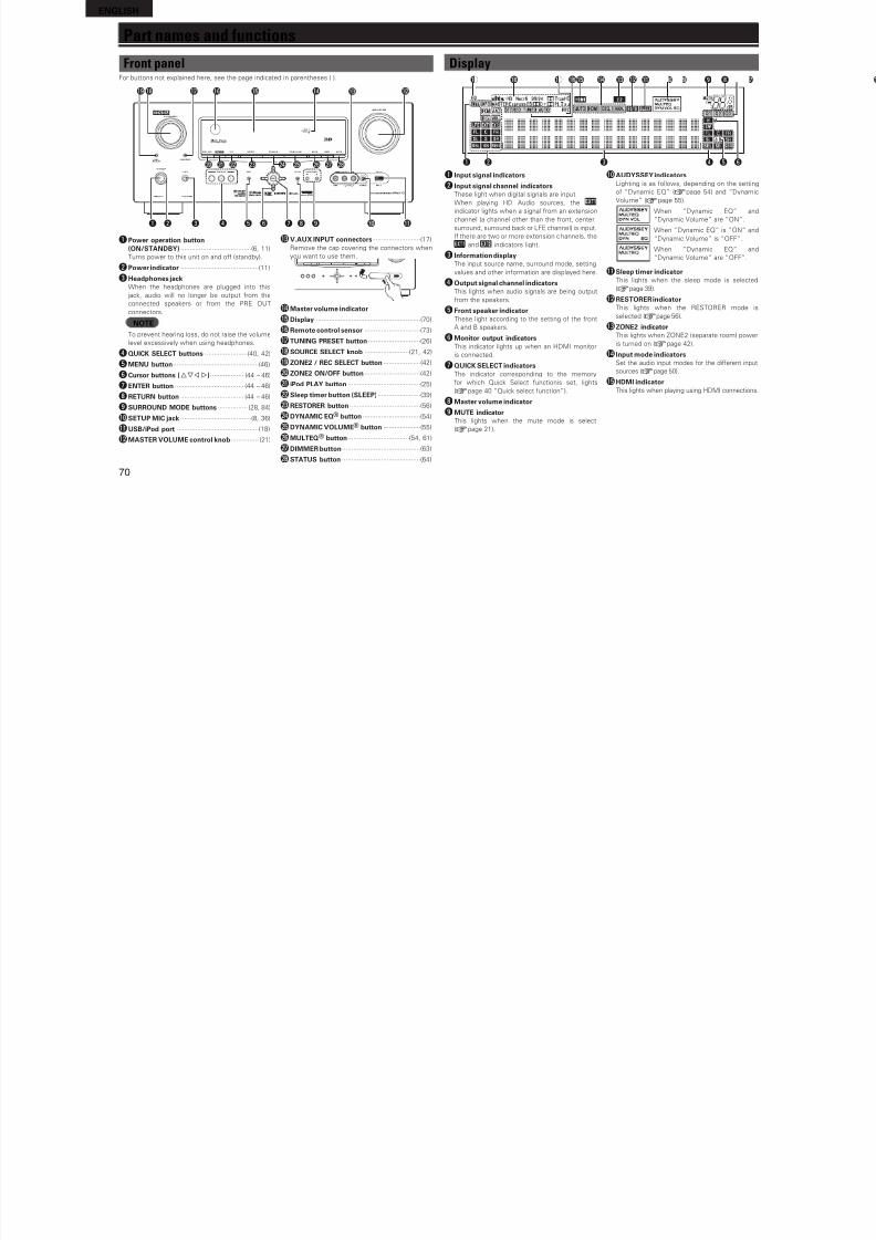
8/7/2019 IBJSC.com | I-WEB.com.vn - 953467670
http://slidepdf.com/reader/full/ibjsccom-i-webcomvn-953467670 73/92
69
B a s i c v e r s i o n
m p l e v e r s i o n
I n f o r m a t i o n
A d v a n c e d v e r s i o n
remote control unitWhen the ZONE SELECT button is pressed, only the set zone can be
operated with the remote control unit.
1Press and hold POWER ON and
ZONE/DEVICE ON for at least 3
seconds.The zone mode indicator ashes twice.
2Press ZONE SELECT.The zone mode indicator ashes twice.
3Press 1 – 3 to set.The zone mode indicator ashes twice.
[Settable items]1 When only using “MAIN ZONE”
2 When using “MAIN ZONE” /
“ZONE2”
3 When using “MAIN ZONE” /
“ZONE2” / “ZONE3” (Deault)
Resetting the remote control unitSettings or the remote control unit are returned to the deault setting.
1Press and hold POWER ON and
ZONE/DEVICE ON for at least 3
seconds.The zone mode indicator ashes twice.
2Press 9, 8 and 1, in that order.“MAIN” indicator ashes our times.
All the settings are restored to their
deaults.
F Part names and functions vpage 70
F Other information vpage 74
F Troubleshooting vpage 82
F Specications vpage 84
F Index vpage 85
InformationHere, we list various inormation related to this unit.Please reer to this inormation as needed.
ENGLISH
Part names and functions
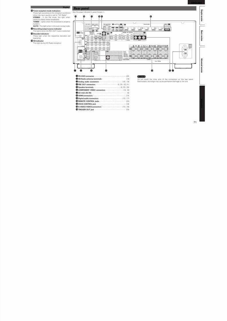
8/7/2019 IBJSC.com | I-WEB.com.vn - 953467670
http://slidepdf.com/reader/full/ibjsccom-i-webcomvn-953467670 74/92
70
Front panelFor buttons not explained here, see the page indicated in parentheses ( ).
q w e r t y u i o
Q3
Q0 Q1
Q2Q4Q5Q6Q7Q8Q9
W0 W1 W2 W4W3 W5 W6 W7 W8
qPower operation button(ON/STANDBY) ······································(6, 11)
Turns power to this unit on and o (standby).wPower indicator ··········································(11)
eHeadphones jackWhen the headphones are plugged into this
jack, audio will no longer be output rom the
connected speakers or rom the PRE OUT
connectors.
NOTETo prevent hearing loss, do not raise the volume
level excessively when using headphones.
rQUICK SELECT buttons ·······················(40, 42)
tMENU button··············································(46)
yCursor buttons (uio p)·················· (44 – 46)
uENTER button ····································· (44 – 46)
iRETURN button ·································· (44 – 46)
oSURROUND MODE buttons ················ (28, 84)
Q0SETUP MIC jack ······································(8, 36)
Q1USB/iPod port ············································(18)
Q2MASTER VOLUME control knob··············· (21)
Q3V.AUX INPUT connectors··························(17)
Remove the cap covering the connectors when
you want to use them.
Q4Master volume indicator
Q5Display·························································(70)
Q6Remote control sensor ······························(73)
Q7 TUNING PRESET button····························(26)
Q8 SOURCE SELECT knob ························(21, 42)
Q9 ZONE2 / REC SELECT button ····················(42)
W0 ZONE2 ON/OFF button ······························(42)
W1 iPod PLAY button ·······································(25)
W2 Sleep timer button (SLEEP)·······················(39)
W3 RESTORER button······································(56)
W4 DYNAMIC EQ® button ·······························(54)
W5 DYNAMIC VOLUME® button ····················(55)
W6 MULTEQ® button ·································(54, 61)
W7 DIMMER button··········································(63)
W8 STATUS button ··········································(64)
DisplayioQ 4Q 6Q 8Q 9 0Q 1Q 3 Q 2Q 5Q 7
wq e r t y
q Input signal indicators
w Input signal channel indicatorsThese light when digital signals are input.
When playing HD Audio sources, the
indicator lights when a signal rom an extension
channel (a channel other than the ront, center,
surround, surround back or LFE channel) is input.
I there are two or more extension channels, the
and indicators light.
e Inormation displayThe input source name, surround mode, setting
values and other inormation are displayed here.
r Output signal channel indicatorsThis lights when audio signals are being output
rom the speakers.
t Front speaker indicatorThese light according to the setting o the ront
A and B speakers.
y Monitor output indicatorsThis indicator lights up when an HDMI monitor
is connected.
u QUICK SELECT indicatorsThe indicator corresponding to the memory
or which Quick Select unctionis set, lights(vpage 40 “Quick select unction”).
i Master volume indicator
o MUTE indicatorThis lights when the mute mode is select
(vpage 21).
Q0 AUDYSSEY indicatorsLighting is as ollows, depending on the setting
o “Dynamic EQ” (vpage 54) and “Dynamic
Volume” (vpage 55).
When “Dynamic EQ” and
“Dynamic Volume” are “ON”.
When “Dynamic EQ” is “ON” and
“Dynamic Volume” is “OFF”.
When “Dynamic EQ” and
“Dynamic Volume” are “OFF”.
Q1 Sleep timer indicatorThis lights when the sleep mode is selected
(vpage 39).
Q2RESTORER indicatorThis lights when the RESTORER mode is
selected (vpage 56).
Q3 ZONE2 indicatorThis lights when ZONE2 (separate room) power
is turned on (vpage 42).
Q4 Input mode indicatorsSet the audio input modes or the dierent input
sources (vpage 50).
Q5HDMI indicatorThis lights when playing using HDMI connections.
ENGLISH
S i m
Rear panelSee the page indicated in parentheses ( )
Q6Tuner reception mode indicators
Display
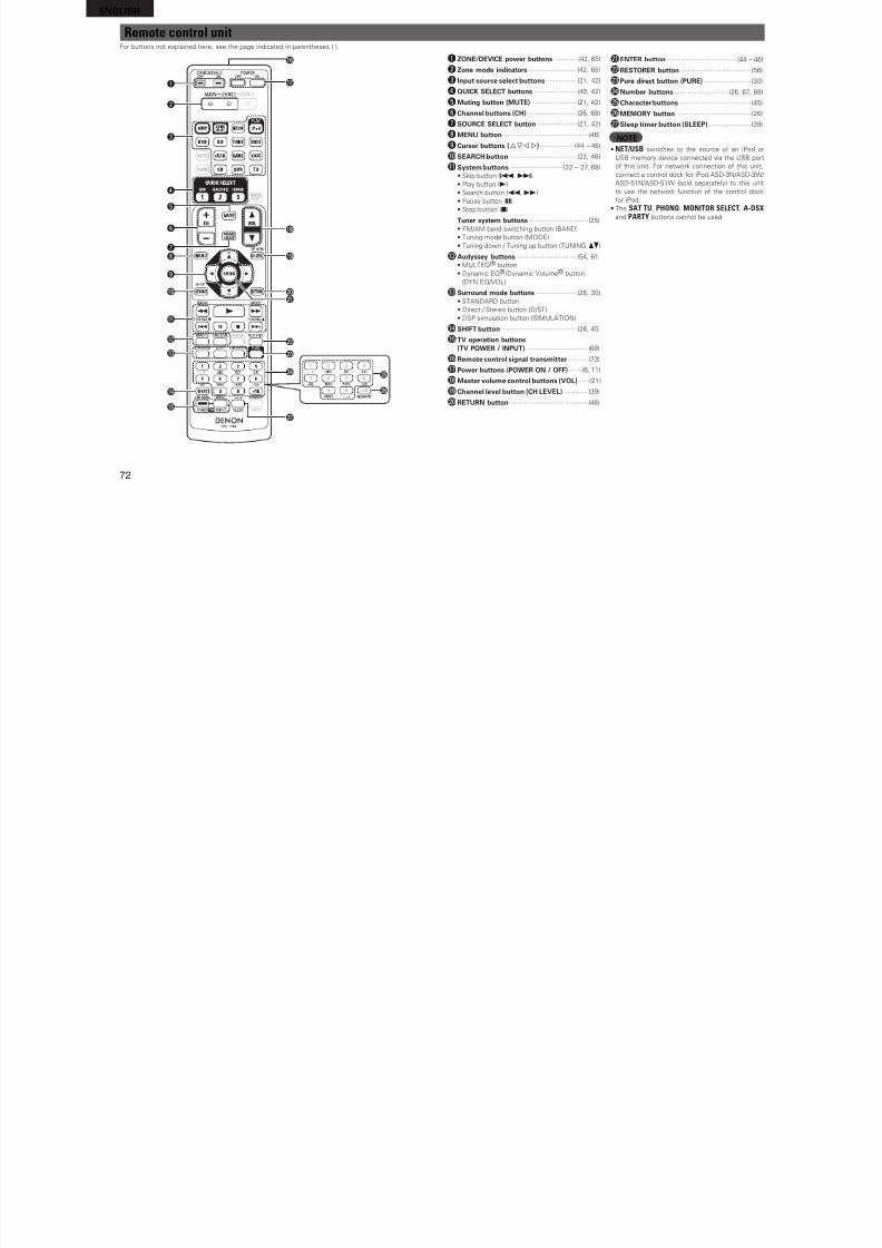
8/7/2019 IBJSC.com | I-WEB.com.vn - 953467670
http://slidepdf.com/reader/full/ibjsccom-i-webcomvn-953467670 75/92
71
B a s i
c v e r s i o n
A d v a n c e d
v e r s i o n
m p l e v e r s i o n
I n f o r m a t i o n
See the page indicated in parentheses ( ).
wq e r yt
ioQ1 Q0Q2Q3
u
qRS-232C connector·································································· (20)
wHD Radio antenna terminals ·················································· (19)
eAnalog audio connectors·················································(16 – 19)
rPRE OUT connectors ··············································(5, 33 – 35, 41)
tSpeaker terminals ························································(5, 33 – 35)
yCOMPONENT VIDEO connectors····································· (15, 16)
uAC inlet (AC IN)·········································································· (5)
iHDMI connectors····································································· (14)
oDigital audio connectors··················································(15 – 17)Q0REMOTE CONTROL jacks ······················································· (20)
Q1DOCK CONTROL jack ······························································ (18)
Q2S-VIDEO/VIDEO connectors············································(15 – 18)
Q3TRIGGER OUT jack ·································································· (20)
NOTEDo not touch the inner pins o the connectors on the rear panel.
Electrostatic discharge may cause permanent damage to the unit.
pThese light according to the reception conditions
when the input source is set to “HD Radio”.
STEREO : In the FM mode, this light when
receiving analog stereo broadcasts.
TUNED : Lights when the broadcast is properly
tuned in.
AUTO : This light when in the auto tuning mode.
Q7 Recording output source indicatorThis lights when the REC OUT mode is selec ted.
Q8 Decoder indicatorsThese light when the respective decoders are
operating.
Q9 HD indicatorThis light during HD Radio reception.
ENGLISH
Remote control unitFor buttons not explained here see the page indicated in parentheses ( )
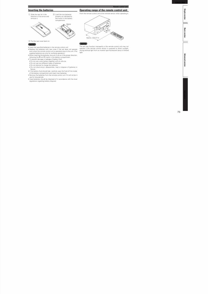
8/7/2019 IBJSC.com | I-WEB.com.vn - 953467670
http://slidepdf.com/reader/full/ibjsccom-i-webcomvn-953467670 76/92
72
For buttons not explained here, see the page indicated in parentheses ( ).
q
w
e
r
t
y
ui
o
Q0
Q1
Q2
Q3
Q4
Q5
W1
W3
W4
W0
W2
Q9
Q8
Q7
Q6
W7
W5
W6
qZONE/DEVICE power buttons ············ (42, 65)
wZone mode indicators ··························(42, 65)
e Input source select buttons·················(21, 42)
rQUICK SELECT buttons ·······················(40, 42)
tMuting button (MUTE) ························(21, 42)
yChannel buttons (CH)···························(26, 68)
uSOURCE SELECT button ·····················(21, 42)
iMENU button··············································(46)oCursor buttons (uio p) ·················· (44 – 46)
Q0SEARCH button ····································(22, 46)
Q1System buttons ···························· (22 – 27, 68)
• Skip button (8, 9)
• Play button (1)
• Search button (6, 7)
• Pause button (3)
• Stop button (2)
Tuner system buttons································(25)
• FM/AM band switching button (BAND)
• Tuning mode button (MODE)
• Tuning down / Tuning up button (TUNING df)
Q2Audyssey buttons ································(54, 61)
• MULTEQ® button
• Dynamic EQ® /Dynamic Volume® button
(DYN EQ/VOL)
Q3Surround mode buttons ······················(28, 30)
• STANDARD button
• Direct / Stereo button (D/ST)
• DSP simulation button (SIMULATION)
Q4SHIFT button·········································(26, 45)
Q5TV operation buttons(TV POWER / INPUT) ·································(68)
Q6Remote control signal transmitter ···········(73)
Q7Power buttons (POWER ON / OFF) ······(6, 11)
Q8Master volume control buttons (VOL) ·····(21)
Q9Channel level button (CH LEVEL) ·············(39)
W0RETURN button ··········································(46)
W1ENTER button ····································· (44 – 46)
W2RESTORER button······································(56)
W3Pure direct button (PURE) ·························(30)
W4Number buttons ·····························(26, 67, 68)
W5Character buttons ······································(45)
W6MEMORY button ········································(26)
W7Sleep timer button (SLEEP)·······················(39)
NOTE• NET/USB switches to the source o an iPod or
USB memory device connected via the USB port
o this unit. For network connection o this unit,
connect a control dock or iPod ASD-3N/ASD-3W/
ASD-51N/ASD-51W (sold separately) to this unit
to use the network unction o the control dock
or iPod.
• The SAT TU, PHONO, MONITOR SELECT, A-DSX
and PARTY buttons cannot be used.
ENGLISH
S i mOperating range of the remote control unit
Remote control unit
Inserting the batteries
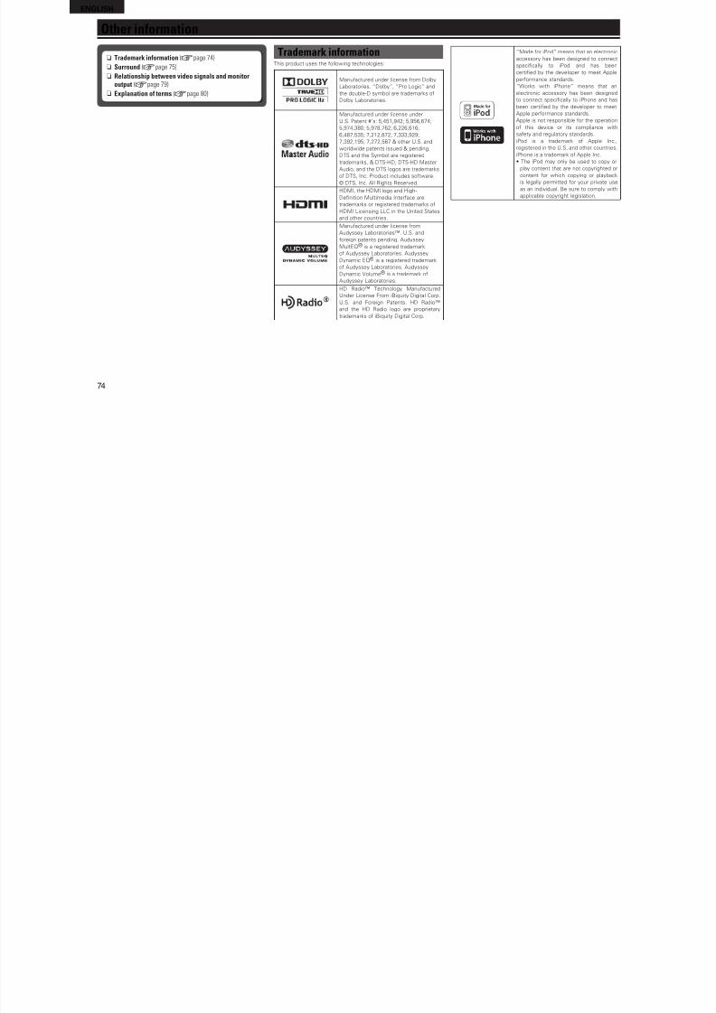
8/7/2019 IBJSC.com | I-WEB.com.vn - 953467670
http://slidepdf.com/reader/full/ibjsccom-i-webcomvn-953467670 77/92
73
B a s i
c v e r s i o n
A d v a n c e d
v e r s i o n
m p l e v e r s i o n
I n f o r m a t i o n
Ope at g a ge o t e e ote co t o u tPoint the remote control unit at the remote sensor when operating it.
30°
30°
Approx. 23 t /7 m
NOTEThe set may unction improperly or the remote control unit may not
operate i the remote control sensor is exposed to direct sunlight,
strong artifcial light rom an inverter type uorescent lamp or inrared
light.
se t g t e batte es
q Slide the rear lid in the
direction o the arrow and
remove it.
w Load the two batteries
properly as indicated by
the marks in the battery
compartment.
R6/AA
e Put the rear cover back on.
NOTE• Insert the specifed batteries in the remote control unit.
• Replace the batteries with new ones i the set does not operate
even when the remote control unit is operated close to the unit. (The
supplied batteries are only or veriying operation.)
• When inserting the batteries, be sure to do so in the proper direction,
ollowing the q and w marks in the battery compartment.
• To prevent damage or leakage o battery uid:
• Do not use a new battery together with an old one.• Do not use two dierent types o batteries.
• Do not attempt to charge dry batteries.
• Do not short-circuit, disassemble, heat or dispose o batteries in
ames.
• I the battery uid should leak, careully wipe the uid o the inside
o the battery compartment and insert new batteries.
• Remove the batteries rom the remote control unit i it will not be in
use or long periods.
• Used batteries should be disposed o in accordance with the local
regulations regarding battery disposal.
ENGLISH
Other information
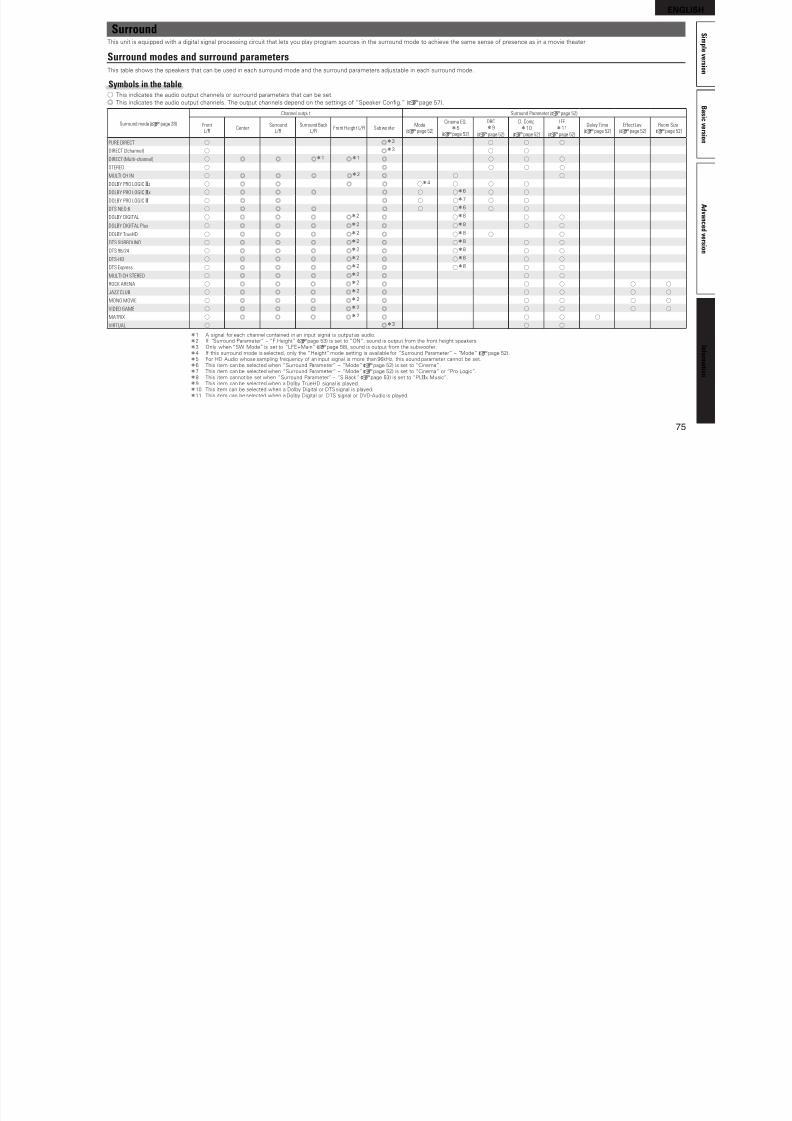
8/7/2019 IBJSC.com | I-WEB.com.vn - 953467670
http://slidepdf.com/reader/full/ibjsccom-i-webcomvn-953467670 78/92
74
n Trademark information (vpage 74)
n Surround (vpage 75)
n Relationship between video signals and monitoroutput (vpage 79)
n Explanation of terms (vpage 80)
Trademark informationThis product uses the ollowing technologies:
Manuactured under license rom Dolby
Laboratories. “Dolby”, “Pro Logic” and
the double-D symbol are trademarks o
Dolby Laboratories.
Manuactured under license under
U.S. Patent #’s: 5,451,942; 5,956,674;
5,974,380; 5,978,762; 6,226,616;
6,487,535; 7,212,872; 7,333,929;
7,392,195; 7,272,567 & other U.S. and
worldwide patents issued & pending.
DTS and the Symbol are registered
trademarks, & DTS-HD, DTS-HD Master
Audio, and the DTS logos are trademarks
o DTS, Inc. Product includes sotware.
© DTS, Inc. All Rights Reserved.
HDMI, the HDMI logo and High-
Defnition Multimedia Interace are
trademarks or registered trademarks o
HDMI Licensing LLC in the United Statesand other countries.
Manuactured under license rom
Audyssey Laboratories™. U.S. and
oreign patents pending. Audyssey
MultEQ® is a registered trademark
o Audyssey Laboratories. Audyssey
Dynamic EQ® is a registered trademark
o Audyssey Laboratories. Audyssey
Dynamic Volume® is a trademark o
Audyssey Laboratories.
HD Radio™ Technology Manuactured
Under License From iBiquity Digital Corp.
U.S. and Foreign Patents. HD Radio™
and the HD Radio logo are proprietary
trademarks o iBiquity Digital Corp.
“Made or iPod” means that an electronic
accessory has been designed to connect
specifcally to iPod and has been
certifed by the developer to meet Apple
perormance standards.
“Works with iPhone” means that an
electronic accessory has been designed
to connect specifcally to iPhone and has
been certifed by the developer to meet
Apple perormance standards.
Apple is not responsible or the operation
o this device or its compliance with
saety and regulatory standards.
iPod is a trademark o Apple Inc.,
registered in the U.S. and other countries.
iPhone is a trademark o Apple Inc.
• The iPod may only be used to copy or
play content that are not copyrighted or
content or which copying or playback
is legally permitted or your private use
as an individual. Be sure to comply with
applicable copyright legislation.
ENGLISH
S i m
SurroundThis unit is equipped with a digital signal processing circuit that lets you play program sources in the surround mode to achieve the same sense o presence as in a movie theater
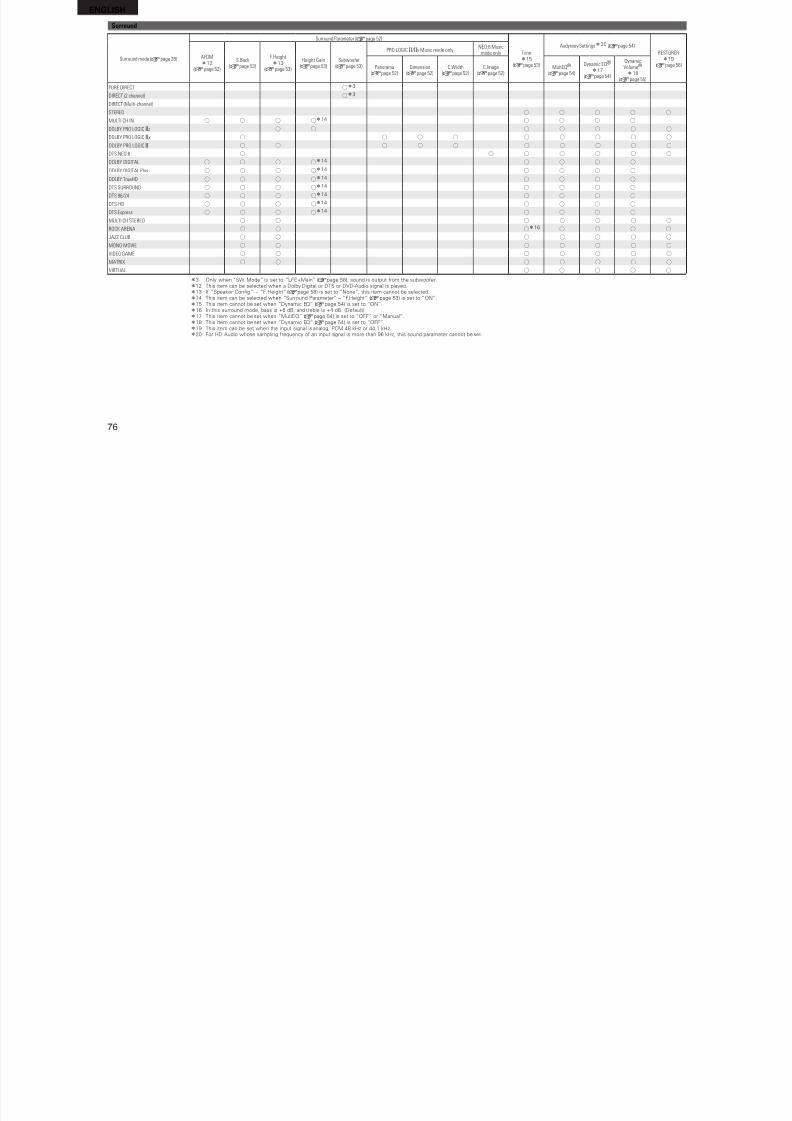
8/7/2019 IBJSC.com | I-WEB.com.vn - 953467670
http://slidepdf.com/reader/full/ibjsccom-i-webcomvn-953467670 79/92
75
B a s i c v e r s i o n
A d v a n c e d
v e r s i o n
m p l e v e r s i o n
I n f o r m a t i o n
This unit is equipped with a digital signal processing circuit that lets you play program sources in the surround mode to achieve the same sense o presence as in a movie theater.
Surround modes and surround parametersThis table shows the speakers that can be used in each surround mode and the surround parameters adjustable in each surround mode.
Symbols in the tableS This indicates the audio output channels or surround parameters that can be set.
D This indicates the audio output channels. The output channels depend on the settings o “Speaker Confg.” (vpage 57).
Surround mode (vpage 28)
Channel output Surround Parameter (vpage 52)
FrontL/R
CenterSurround
L/RSurround Back
L/RFront Height L/R Subwoofer
Mode(vpage 52)
Cinema EQ.z5
(vpage 52)
DRCz9
(vpage 52)
D. Compz10
(vpage 52)
LFEz11
(vpage 52)
Delay Time(vpage 52)
Effect Lev.(vpage 52)
Room Size(vpage 52)
PURE DIRECT S Dz3 S S S
DIRECT (2channel) S Dz3 S S
DIRECT (Multi-channel) S D D Dz1 Dz1 D S S S
STEREO S D S S S
MULTI CH IN S D D D Dz2 D S S
DOLBY PRO LOGIC gz S D D D D Sz4 S S S
DOLBY PRO LOGIC gx S D D D D S Sz6 S S
DOLBY PRO LOGIC g S D D D S Sz7 S S
DTS NEO:6 S D D D D S Sz6 S S
DOLBY DIGITAL S D D D Dz2 D Sz8 S S
DOLBY DIGITAL Plus S D D D Dz2 D Sz8 S S
DOLBY TrueHD S D D D Dz2 D Sz8 S SDTS SURROUND S D D D Dz2 D Sz8 S S
DTS 96/24 S D D D Dz2 D Sz8 S S
DTS-HD S D D D Dz2 D Sz8 S S
DTS Express S D D D Dz2 D Sz8 S S
MULTI CH STEREO S D D D Dz2 D S S
ROCK ARENA S D D D Dz2 D S S S S
JAZZ CLUB S D D D Dz2 D S S S S
MONO MOVIE S D D D Dz2 D S S S S
VIDEO GAME S D D D Dz2 D S S S S
MATRIX S D D D Dz2 D S S S
VIRTUAL S Dz3 S S
z1 A signal or each channel contained in an input signal is output as audio.z2 I “Surround Parameter” – “F.Height” (vpage 53) is set to “ON”, sound is output rom the ront height speakers.
z3 Only when “SW Mode” is set to “LFE+Main” (vpage 58), sound is output rom the subwooer.z4 I this surround mode is selected, only the “Height” mode setting is available or “Surround Parameter” – “Mode” (vpage 52).
z5 For HD Audio whose sampling requency o an input signal is more than 96kHz, this sound parameter cannot be set.
z6 This item can be selected when “Surround Parameter” – “Mode” (vpage 52) is set to “Cinema”.
z7 This item can be selected when “Surround Parameter” – “Mode” (vpage 52) is set to “Cinema” or “Pro Logic”.z8 This item cannot be set when “Surround Parameter” – “S.Back” (vpage 53) is set to “PLgx Music”.z9 This item can be selected when a Dolby TrueHD signal is played.z10 This item can be selected when a Dolby Digital or DTS signal is played.
z11 This item can be selected when a Dolby Digital or DTS signal or DVD-Audio is played.
ENGLISHSurround
Surround Parameter (vpage 52)
S z20 ( )
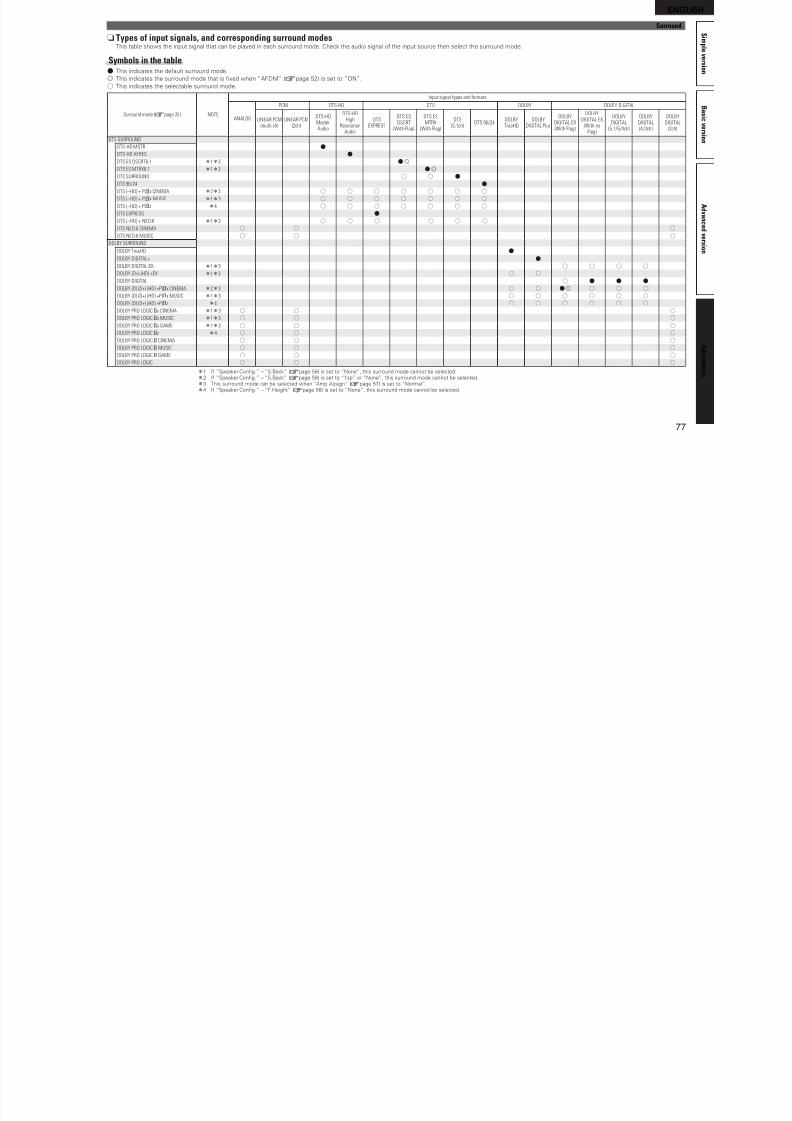
8/7/2019 IBJSC.com | I-WEB.com.vn - 953467670
http://slidepdf.com/reader/full/ibjsccom-i-webcomvn-953467670 80/92
76
Surround mode (vpage 28)Tonez15
(vpage 53)
Audyssey Settingsz20 (vpage 54)
RESTORERz19
(vpage 56)
AFDMz12
(vpage 52)
S.Back(vpage 53)
F.Heightz13
(vpage 53)
Height Gain(vpage 53)
Subwoofer(vpage 53)
PRO LOGIC g /gx Music mode onlyNEO:6 Music
mode only
Panorama(vpage 52)
Dimension(vpage 52)
C.Width(vpage 52)
C.Image(vpage 52)
MultEQ® (vpage 54)
Dynamic EQ®
z17 (vpage 54)
DynamicVolume® z18
(vpage 55)
PURE DIRECT Sz3
DIRECT (2 channel) Sz3
DIRECT (Multi-channel)
STEREO S S S S S
MULTI CH IN S S S Sz14
S S S SDOLBY PRO LOGIC gz S S S S S S S
DOLBY PRO LOGIC gx S S S S S S S S S
DOLBY PRO LOGIC g S S S S S S S S S S
DTS NEO:6 S S S S S S S
DOLBY DIGITAL S S S Sz14 S S S S
DOLBY DIGITAL Plus S S S Sz14 S S S S
DOLBY TrueHD S S S Sz14 S S S S
DTS SURROUND S S S Sz14 S S S S
DTS 96/24 S S S Sz14 S S S S
DTS-HD S S S Sz14 S S S S
DTS Express S S S Sz14 S S S S
MULTI CH STEREO S S S S S S S
ROCK ARENA S S Sz16 S S S S
JAZZ CLUB S S S S S S S
MONO MOVIE S S S S S S S
VIDEO GAME S S S S S S S
MATRIX S S S S S S S
VIRTUAL S S S S S
z3 Only when “SW Mode” is set to “LFE+Main” (vpage 58), sound is output rom the subwooer.z12 This item can be selected when a Dolby Digital or DTS or DVD-Audio signal is played.z13 I “Speaker Confg.” – “F.Height” (vpage 58) is set to “None”, this item cannot be selected.
z14 This item can be selected when “Surround Parameter” – “F.Height” (vpage 53) is set to “ON”.
z15 This item cannot be set when “Dynamic EQ” (vpage 54) is set to “ON”.
z16 In this surround mode, bass is +6 dB, and treble is +4 dB. (Deault)
z17 This item cannot be set when “MultEQ” (vpage 54) is set to “OFF” or “Manual”.
z18 This item cannot be set when “Dynamic EQ” (vpage 54) is set to “OFF”.z19 This item can be set when the input signal is analog, PCM 48 kHz or 44.1 kHz.z20 For HD Audio whose sampling requency o an input signal is more than 96 kHz, this sound parameter cannot be set.
ENGLISH
S i m p
Surround
n Types of input signals, and corresponding surround modesThi bl h h i i l h b l d i h d d Ch k h di i l h i h l h d d
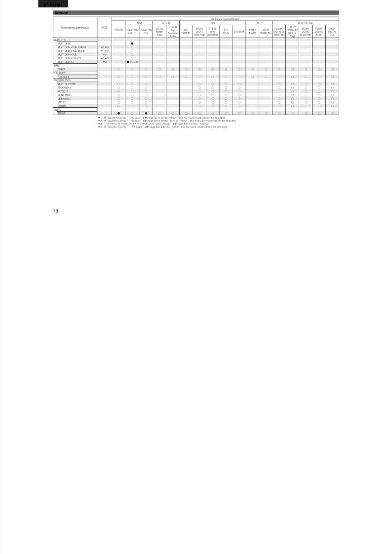
8/7/2019 IBJSC.com | I-WEB.com.vn - 953467670
http://slidepdf.com/reader/full/ibjsccom-i-webcomvn-953467670 81/92
77
B a s i c v e r s i o n
A d v a n c e d
v e r s i o n
pl e v e r s i o n
I n f o r m a t i o n
This table shows the input signal that can be played in each surround mode. Check the audio signal o the input source then select the surround mode.
Symbols in the tableF This indicates the deault surround mode.
D This indicates the surround mode that is fxed when “AFDM” (vpage 52) is set to “ON”.
S This indicates the selectable surround mode.
Surround mode (vpage 28) NOTE
Input signal types and formats
ANALOG
PCM DTS-HD DTS DOLBY DOLBY DIGITAL
LINEAR PCM(multi ch)
LINEAR PCM(2ch)
DTS-HD
MasterAudio
DTS-HDHigh
ResolutionAudio
DTSEXPRESS
DTS ES
DSCRT(With Flag)
DTS ES
MTRX(With Flag)
DTS(5.1ch) DTS 96/24
DOLBYTrueHD
DOLBYDIGITAL Plus
DOLBY
DIGITAL EX(With Flag)
DOLBYDIGITAL EX
(With noFlag)
DOLBY
DIGITAL(5.1/5/4ch)
DOLBY
DIGITAL(4/3ch)
DOLBY
DIGITAL(2ch)
DTS SURROUND
DTS-HD MSTR F
DTS-HD HI RES F
DTS ES DSCRT6.1 z1z3 F D
DTS ES MTRX6.1 z1z3 F D
DTS SURROUND S S F
DTS 96/24 F
DTS (–HD) + PLgx CINEMA z2z3 S S S S S S S
DTS (–HD) + PLgx MUSIC z1z3 S S S S S S S
DTS (–HD) + PLgz z4 S S S S S S S
DTS EXPRESS F
DTS (–HD) + NEO:6 z1z3 S S S S S S
DTS NEO:6 CINEMA S S S
DTS NEO:6 MUSIC S S SDOLBY SURROUND
DOLBY TrueHD F
DOLBY DIGITAL+ F
DOLBY DIGITAL EX z1z3 S S S S
DOLBY (D+) (HD) +EX z1z3 S S
DOLBY DIGITAL S F F F
DOLBY (D) (D+) (HD) +PLgx CINEMA z2z3 S S F D S S S
DOLBY (D) (D+) (HD) +PLgx MUSIC z1z3 S S S S S S
DOLBY (D) (D+) (HD) +PLgz z4 S S S S S S
DOLBY PRO LOGIC gx CINEMA z1z3 S S S
DOLBY PRO LOGIC gx MUSIC z1z3 S S S
DOLBY PRO LOGIC gx GAME z1z3 S S S
DOLBY PRO LOGIC gz z4 S S S
DOLBY PRO LOGIC g CINEMA S S S
DOLBY PRO LOGIC g MUSIC S S SDOLBY PRO LOGIC g GAME S S S
DOLBY PRO LOGIC S S S
z1 I “Speaker Confg.” – “S.Back” (vpage 58) is set to “None”, this surround mode cannot be selected.
z2 I “Speaker Confg.” – “S.Back” (vpage 58) is set to “1sp” or “None”, this surround mode cannot be selected.
z3 This surround mode can be selected when “Amp Assign” (vpage 57) is set to “Normal”.
z4 I “Speaker Confg.” – “F.Height” (vpage 58) is set to “None”, this surround mode cannot be selected.
ENGLISHSurround
Input signal types and formats
PCM DTS HD DTS DOLBY DOLBY DIGITAL
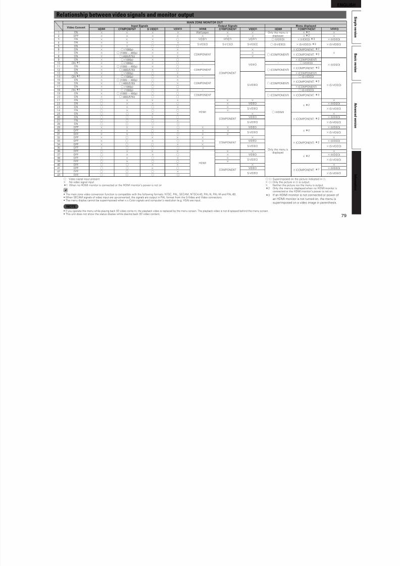
8/7/2019 IBJSC.com | I-WEB.com.vn - 953467670
http://slidepdf.com/reader/full/ibjsccom-i-webcomvn-953467670 82/92
78
Surround mode (vpage 28) NOTEANALOG
PCM DTS-HD DTS DOLBY DOLBY DIGITAL
LINEAR PCM(multi ch)
LINEAR PCM(2ch)
DTS-HDMasterAudio
DTS-HDHigh
ResolutionAudio
DTSEXPRESS
DTS ESDSCRT
(With Flag)
DTS ESMTRX
(With Flag)
DTS(5.1ch)
DTS 96/24DOLBYTrueHD
DOLBYDIGITAL Plus
DOLBYDIGITAL EX(With Flag)
DOLBYDIGITAL EX
(With noFlag)
DOLBYDIGITAL
(5.1/5/4ch)
DOLBYDIGITAL(4/3ch)
DOLBYDIGITAL
(2ch)
MULTI CH IN
MULTI CH IN F
MULTI CH IN + PLgx CINEMA z2z3 S
MULTI CH IN + PLgx MUSIC z1z3 S
MULTI CH IN + PLgz z4 S
MULTI CH IN + Dolby EX z1z3 S
MULTI CH IN 7.1 z3 F D (7.1)
DIRECT
DIRECT S S S S S S S S S S S S S S S S S
PURE DIRECT
PURE DIRECT S S S S S S S S S S S S S S S S S
DSP SIMULATION
MULTI CH STEREO S S S S S S S S S S S S
ROCK ARENA S S S S S S S S S S S S
JAZZ CLUB S S S S S S S S S S S S
MONO MOVIE S S S S S S S S S S S S
VIDEO GAME S S S S S S S S S S S S
MATRIX S S S S S S S S S S S S
VIRTUAL S S S S S S S S S S S S
STEREO
STEREO F S F S S S S S S S S S S S S S S
z1 I “Speaker Confg.” – “S.Back” (vpage 58) is set to “None”, this surround mode cannot be selected.z2 I “Speaker Confg.” – “S.Back” (vpage 58) is set to “1sp” or “None”, this surround mode cannot be selected.
z3 This surround mode can be selected when “Amp Assign” (vpage 57) is set to “Normal”.
z4 I “Speaker Confg.” – “F.Height” (vpage 58) is set to “None”, this surround mode cannot be selected.
ENGLISH
S i m p
Relationship between video signals and monitor outputMAIN ZONE MONITOR OUT
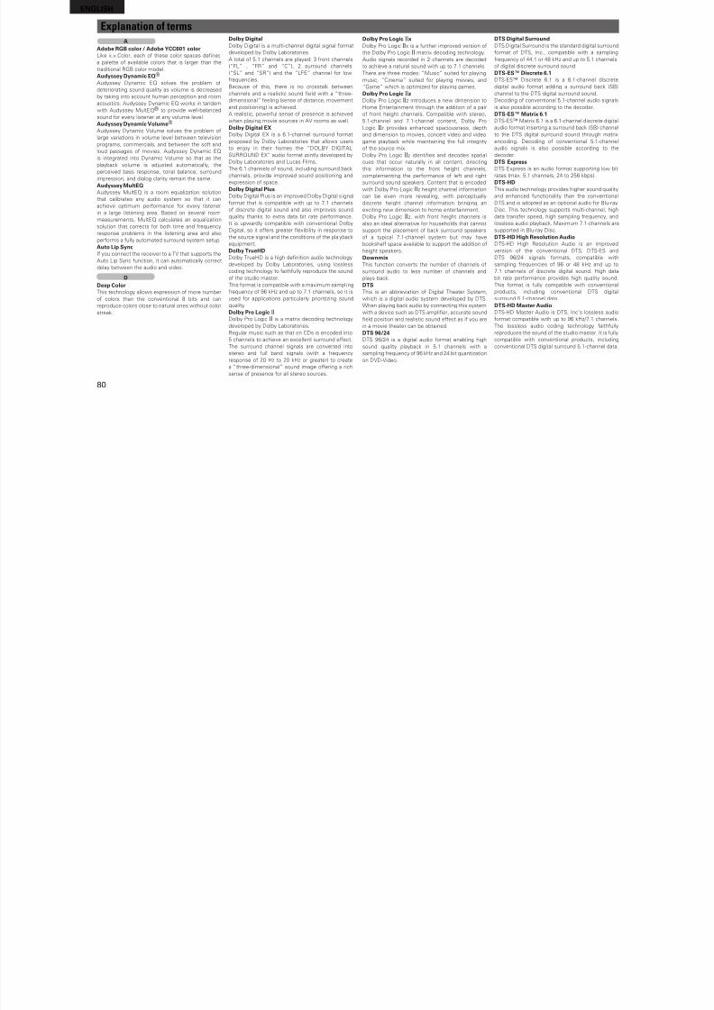
8/7/2019 IBJSC.com | I-WEB.com.vn - 953467670
http://slidepdf.com/reader/full/ibjsccom-i-webcomvn-953467670 83/92
79
B a s i c v e r s i o n
A d v a n c e d
v e r s i o n
pl e v e r s i o n
I n f o r m a t i o n
MAIN ZONE MONITOR OUT
Video ConvertInput Signals Output Signals Menu displayed
HDMI COMPONENT S-VIDEO VIDEO HDMI COMPONENT VIDEO HDMI COMPONENT VIDEO1 ON A A A A Wall paper A A Only the menu is
displayedA z2 A
2 OFF A A A A A A A A z2 A3 ON A A A S VIDEO VIDEO VIDEO S (VIDEO) A (VIDEO) z3 A (VIDEO)
4 ON A A S AS-VIDEO S-VIDEO S-VIDEO S (S-VIDEO) A (S-VIDEO) z3 A (S-VIDEO)
5 ON A A S S6 ON A S (1080p) A A
COMPONENT
COMPONENT
A
S (COMPONENT)
A (COMPONENT) z2
A7 ON A S (1080i ~ 480p) A A AA (COMPONENT) z3
8 ON A S (480i/576i) A A A9 ON A S (1080p) A S
VIDEO
A (COMPONENT)
A (VIDEO)10 ON z1 A S (1080p) A S – – S (VIDEO)11 ON A S (1080i ~ 480p) A S
COMPONENT S (COMPONENT)A (COMPONENT) z3
12 ON A S (480i/576i) A S13 ON A S (1080p) S A
S-VIDEO
A (COMPONENT)
A (S-VIDEO)
14 ON z1 A S (1080p) S A – – S (S-VIDEO)
15 ON A S (1080i ~ 480p) S ACOMPONENT S (COMPONENT)
A (COMPONENT) z316 ON A S (480i/576i) S A17 ON A S (1080p) S S A (COMPONENT)
18 ON z1 A S (1080p) S A – – S (S-VIDEO)
19 ON A S (1080i ~ 480p) S SCOMPONENT S (COMPONENT) A (COMPONENT) z3
20 ON A S (480i/576i) S S21 ON S A A A
HDMI
A A
S (HDMI)
A z2
A22 ON S A A S A VIDEO A (VIDEO)
23 ON S A S A AS-VIDEO A (S-VIDEO)
24 ON S A S S A25 ON S S A A
COMPONENT
A
A (COMPONENT) z2
A26 ON S S A S VIDEO A (VIDEO)
27 ON S S S AS-VIDEO A (S-VIDEO)
28 ON S S S S29 OFF A A A S A A VIDEO
Only the menu isdisplayed
A z2A (VIDEO)
30 OFF A A S A A AS-VIDEO A (S-VIDEO)
31 OFF A A S S A A32 OFF A S A A A
COMPONENT
A
A (COMPONENT) z2
A33 OFF A S A S A VIDEO A (VIDEO)
34 OFF A S S A AS-VIDEO A (S-VIDEO)
35 OFF A S S S A36 OFF S A A A
HDMI
A A
A z2
A37 OFF S A A S A VIDEO A (VIDEO)
38 OFF S A S A AS-VIDEO A (S-VIDEO)
39 OFF S A S S A40 OFF S S A A
COMPONENT
A
A (COMPONENT) z2
A41 OFF S S A S VIDEO A (VIDEO)
42 OFF S S S AS-VIDEO A (S-VIDEO)
43 OFF S S S SS Video signal input present
A No video signal input
z1 When no HDMI monitor is connected or the HDMI monitor’s power is not on
• The main zone video conversion unction is compatible with the ollowing ormats: NTSC, PAL, SECAM, NTSC4.43, PAL-N, PAL-M and PAL-60.• When SECAM signals o video input are up-converted, the signals are output in PAL ormat rom the S-Video and Video connectors.• The menu display cannot be superimposed when x.v.Color signals and computer’s resolution (e.g. VGA) are input.
NOTE• I you operate the menu while playing back 3D video conte nt, the playback video is replaced by the menu screen. The playback video is not di splayed behind the menu screen.• This unit does not show the status display while playing back 3D video content.
S ( ) Superimposed on the picture indicated in ( ).
A ( ) Only the picture in ( ) is output.
A Neither the picture nor the menu is output.
z2 Only the menu is displayed when no HDMI monitor isconnected or the HDMI monitor’s power is not on.
z3 I an HDMI monitor is not connected or power o
an HDMI monitor is not turned on, the menu is
superimposed on a video image in parenthesis.
ENGLISH
Explanation of termsA Dolby Digital Dolby Pro Logic gx DTS Digital Surround
8/7/2019 IBJSC.com | I-WEB.com.vn - 953467670
http://slidepdf.com/reader/full/ibjsccom-i-webcomvn-953467670 84/92
80
AAdobe RGB color / Adobe YCC601 colorLike x.v.Color, each o these color spaces defnes
a palette o available colors that is larger than the
traditional RGB color model.
Audyssey Dynamic EQ®
Audyssey Dynamic EQ solves the problem o
deteriorating sound quality as volume is decreased
by taking into account human perception and room
acoustics. Audyssey Dynamic EQ works in tandem
with Audyssey MultEQ® to provide well-balancedsound or every listener at any volume level.
Audyssey Dynamic Volume®
Audyssey Dynamic Volume solves the problem o
large variations in volume level between television
programs, commercials, and between the sot and
loud passages o movies. Audyssey Dynamic EQ
is integrated into Dynamic Volume so that as the
playback volume is adjusted automatically, the
perceived bass response, tonal balance, surround
impression, and dialog clarity remain the same.
Audyssey MultEQAudyssey MultEQ is a room equalization solution
that calibrates any audio system so that it can
achieve optimum perormance or every listener
in a large listening area. Based on several roommeasurements, MultEQ calculates an equalization
solution that corrects or both time and requency
response problems in the listening area and also
perorms a ully automated surround system setup.
Auto Lip SyncI you connect the receiver to a TV that supports the
Auto Lip Sync unction, it can automatically correct
delay between the audio and video.
DDeep ColorThis technology allows expression o more number
o colors than the conventional 8 bits and can
reproduce colors close to natural ones without color
streak.
y gDolby Digital is a multi-channel digital signal ormat
developed by Dolby Laboratories.
A total o 5.1 channels are played: 3 ront channels
(“FL” , “FR” and “C”), 2 surround channels
(“SL” and “SR”) and the “LFE” channel or low
requencies.
Because o this, there is no crosstalk between
channels and a realistic sound feld with a “three-
dimensional” eeling (sense o distance, movement
and positioning) is achieved.
A realistic, powerul sense o presence is achieved
when playing movie sources in AV rooms as well.
Dolby Digital EXDolby Digital EX is a 6.1-channel surround ormat
proposed by Dolby Laboratories that allows users
to enjoy in their homes the “DOLBY DIGITAL
SURROUND EX” audio ormat jointly developed by
Dolby Laboratories and Lucas Films.
The 6.1 channels o sound, including surround back
channels, provide improved sound positioning and
expression o space.
Dolby Digital PlusDolby Digital Plus is an improved Dolby Digital s ignal
ormat that is compatible with up to 7.1 channels
o discrete digital sound and also improves soundquality thanks to extra data bit rate perormance.
It is upwardly compatible with conventional Dolby
Digital, so it oers greater exibility in response to
the source signal and the conditions o the playback
equipment.
Dolby TrueHDDolby TrueHD is a high defnition audio technology
developed by Dolby Laboratories, using lossless
coding technology to aithully reproduce the sound
o the studio master.
This ormat is compatible with a maximum sampli ng
requency o 96 kHz and up to 7.1 channels, so it is
used or applications particularly prioritizing sound
quality.
Dolby Pro Logic gDolby Pro Logic g is a matrix decoding technology
developed by Dolby Laboratories.
Regular music such as that on CDs is encoded into
5 channels to achieve an excellent surround eect.
The surround channel signals are converted into
stereo and ull band signals (with a requency
response o 20 Hz to 20 kHz or greater) to create
a “three-dimensional” sound image oering a rich
sense o presence or all stereo sources.
y gDolby Pro Logic gx is a urther improved version o
the Dolby Pro Logic g matrix decoding technology.
Audio signals recorded in 2 channels are decoded
to achieve a natural sound with up to 7.1 channels.
There are three modes: “Music” suited or playing
music, “Cinema” suited or playing movies, and
“Game” which is optimized or playing games.
Dolby Pro Logic gzDolby Pro Logic gz introduces a new dimension to
Home Entertainment through the addition o a pair
o ront height channels. Compatible with stereo,
5.1-channel and 7.1-channel content, Dolby Pro
Logic gz provides enhanced spaciousness, depth
and dimension to movies, concert video and video
game playback while maintaining the ull integrity
o the source mix.
Dolby Pro Logic gz identifes and decodes spatial
cues that occur naturally in all content, directing
this inormation to the ront height channels,
complementing the perormance o let and right
surround sound speakers. Content that is encoded
with Dolby Pro Logic gz height channel inormation
can be even more revealing, with perceptually
discrete height channel inormation bringing an
exciting new dimension to home entertainment.Dolby Pro Logic gz, with ront height channels is
also an ideal alternative or households that cannot
support the placement o back surround speakers
o a typical 7.1-channel system but may have
bookshel space available to support the addition o
height speakers.
DownmixThis unction converts the number o channels o
surround audio to less number o channels and
plays back.
DTSThis is an abbreviation o Digital Theater System,
which is a digital audio system developed by DTS.
When playing back audio by connecting this system
with a device such as DTS amplifer, accurate soundfeld position and realistic sound eect as i you are
in a movie theater can be obtained.
DTS 96/24DTS 96/24 is a digital audio ormat enabling high
sound quality playback in 5.1 channels with a
sampling requency o 96 kHz and 24 bit quantization
on DVD-Video.
gDTS Digital Surround is the standard digital surround
ormat o DTS, Inc., compatible with a sampling
requency o 44.1 or 48 kHz and up to 5.1 channels
o digital discrete surround sound.
DTS-ES™ Discrete 6.1DTS-ES™ Discrete 6.1 is a 6.1-channel discrete
digital audio ormat adding a surround back (SB)
channel to the DTS digital surround sound.
Decoding o conventional 5.1-channel audio signals
is also possible according to the decoder.
DTS-ES™ Matrix 6.1DTS-ES™ Matrix 6.1 is a 6.1-channel discrete digital
audio ormat inserting a surround back (SB) channel
to the DTS digital surround sound through matrix
encoding. Decoding o conventional 5.1-channel
audio signals is also possible according to the
decoder.
DTS ExpressDTS Express is an audio ormat supporting low bit
rates (max. 5.1 channels, 24 to 256 kbps).
DTS-HDThis audio technology provides higher sound quality
and enhanced unctionality than the conventional
DTS and is adopted as an optional audio or Blu-ray
Disc. This technology supports multi-channel, highdata transer speed, high sampling requency, and
lossless audio playback. Maximum 7.1-channels are
supported in Blu-ray Disc.
DTS-HD High Resolution AudioDTS-HD High Resolution Audio is an improved
version o the conventional DTS, DTS-ES and
DTS 96/24 signals ormats, compatible with
sampling requencies o 96 or 48 kHz and up to
7.1 channels o discrete digital sound. High data
bit rate perormance provides high quality sound.
This ormat is ully compatible with conventional
products, including conventional DTS digital
surround 5.1-channel data.
DTS-HD Master Audio
DTS-HD Master Audio is DTS, Inc’s lossless audioormat compatible with up to 96 kHz/7.1 channels.
The lossless audio coding technology aithully
reproduces the sound o the studio master. It is ully
compatible with conventional products, including
conventional DTS digital surround 5.1-channel data.
ENGLISH
S i m p
DTS NEO:6™ SurroundDTS NEO:6™ is a matrix decoding technology
Explanation of terms
PProgressive(sequentialscanning)
Xx v Color
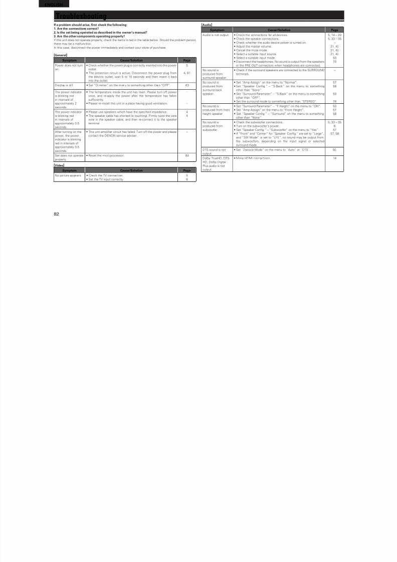
8/7/2019 IBJSC.com | I-WEB.com.vn - 953467670
http://slidepdf.com/reader/full/ibjsccom-i-webcomvn-953467670 85/92
81
B a s i c v e r s i o n
A d v a n c e d
v e r s i o n
pl e v e r s i o n
I n f o r m a t i o n
g gy
or achieving 6.1-channel surround playback
with 2-channel sources. It includes “DTS NEO:6
Cinema” suited or playing movies and “DTS
NEO:6 Music” suited or playing music.
Dynamic rangeThe dierence between the maximum undistorted
sound level and the minimum discernible level
above the noise emitted by the device.
H
HDCPWhen transmitting digital signals between devices,
this copyright protection technology encrypts
the signals to prevent content rom being copied
without authorization.
HDMIThis is an abbreviation o High-Defnition Multimedia
Interace, which is an AV digital interace that can
be connected to a TV or amplifer. Video signal and
audio signal can be connected using 1 cable.
LLFEThis is an abbreviation o Low Frequency Eect,
which is an output channel that emphasizes
low requency eect sound. Surround audio isintensifed by outputting 20 Hz to 120 Hz deep
bass.
MMAIN ZONEThe room where this unit is placed is called the
MAIN ZONE.
MP3 (MPEG Audio Layer-3)This is an internationally standardized audio data
compression scheme, using the “MPEG-1” video
compression standard. It compresses the data
volume to about one eleventh its original size while
maintaining sound quality equivalent to a music CD.
MPEG (Moving Picture Experts Group), MPEG-2,
MPEG-4These are the names or digital compression ormat
standards used or the encoding o video and audio.
Video standards include “MPEG-1 Video”, “MPEG-
2 Video”, “MPEG-4 Visual”, “MPEG-4 AVC”. Audio
standards include “MPEG-1 Audio”, “MPEG-2
Audio”, “MPEG-4 AAC”.
Progressive (sequential scanning)This is a scanning system o video signal that
displays 1 rame o video as one image. Compared
to the interlace system, this system provides
images with less ickering and bleeding.
Protection CircuitThis is a unction to prevent damage to components
within the power supply when an abnormality
such as an overload, excess voltage occurs or
temperature or any reason.
In this unit, the power indicator blinks and the unitenters standby mode when an abnormality occurs.
SSampling requencySampling involves taking a reading o a sound wave
(analog signal) at regular intervals and expressing
the height o the wave at each reading in digitized
ormat (producing a digital signal).
The number o readings taken in one second is
called the “sampling requency”. The larger the
value, the closer the reproduced sound is to the
original.
Speaker impedanceThis is an AC resistance value, indicated in Ω
(ohms). Greater power can be obtained with thisvalue smaller.
sYCC601 colorLike x.v.Color, each o these color spaces defnes
a palette o available colors that is larger than the
traditional RGB color model.
WWMA (Windows Media Audio)This is audio compression technology developed by
Microsot Corporation.
WMA data can be encoded using Windows
Media® Player Ver.7, 7.1, Windows Media®Player
or Windows® XP and Windows Media® Player 9
Series.
To encode WMA fles, only use applications
authorized by Microsot Corporation. I you use
an unauthorized application, the fle may not work
properly.
x.v.ColorThis unction lets HDTVs display colors more
accurately. It enables display with natural, vivid
colors. “x.v.Color” is a Sony registered trademark.
ZZONE2This unit can operate in a room other than the room
where this unit is placed (MAIN ZONE) (ZONE2
playback). The room or ZONE2 playback is called
ZONE2.
ENGLISH
I bl h ld i f h k h ll i
TroubleshootingG H
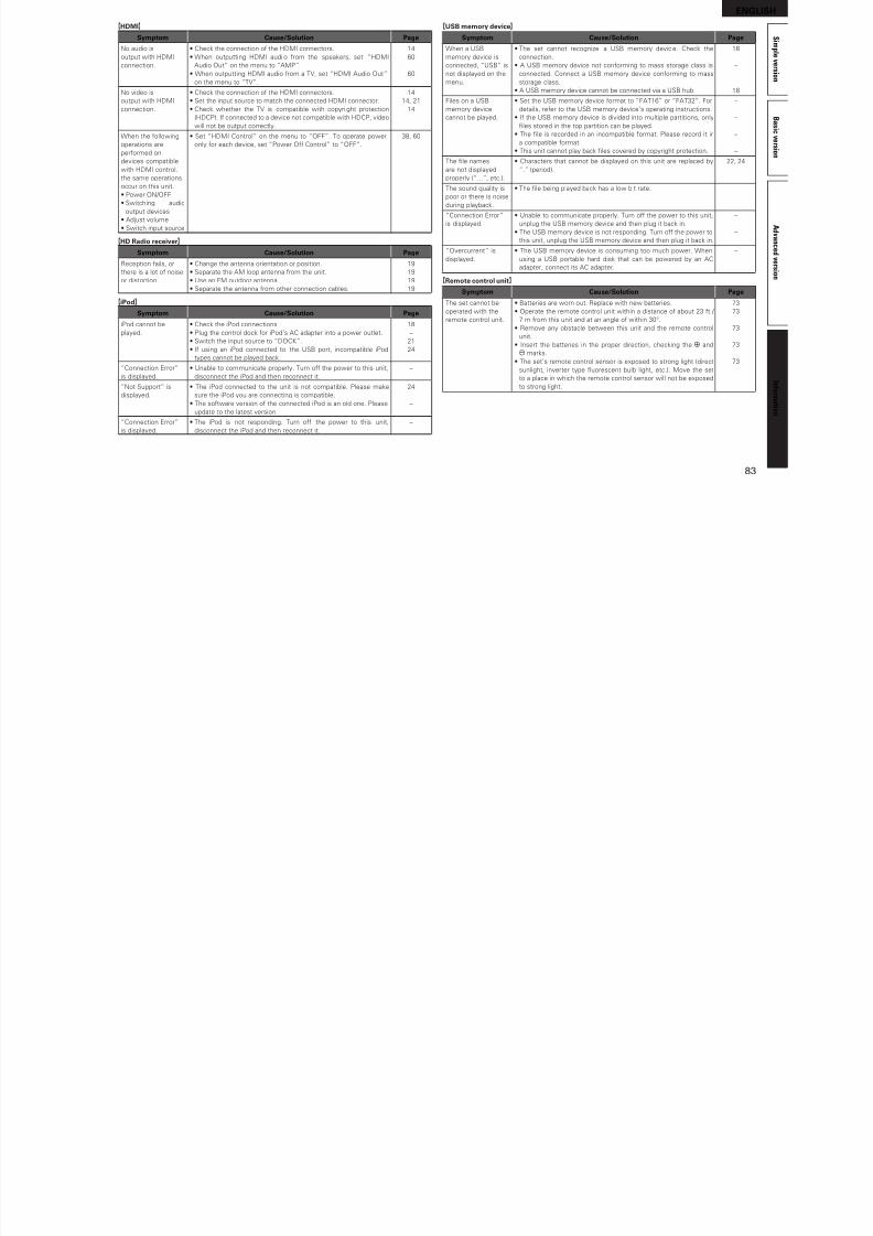
8/7/2019 IBJSC.com | I-WEB.com.vn - 953467670
http://slidepdf.com/reader/full/ibjsccom-i-webcomvn-953467670 86/92
82
I a problem should arise, frst check the ollowing:1. Are the connections correct?2. Is the set being operated as described in the owner’s manual?3. Are the other components operating properly?I this unit does not operate properly, check the items lis ted in the table below. Should the problem persist,
there may be a malunction.
In this case, disconnect the power immediately and contact your store o purchase.
GGeneralH
Symptom Cause/Solution PagePower does not turn
on.
• Check whether the power plug is correctly inserted into the power
outlet.
• The protection circuit is active. Disconnect the power plug rom
the electric outlet, wait 5 to 10 seconds and then insert it back
into the outlet.
5
4, 81
Displ ay is o . • Set “Di mmer” on the menu to somethi ng other than “OFF”. 63
The power indicator
is blinking red
in intervals o
approximately 2
seconds.
• The temperature inside the unit has risen. Please turn o power
once, and re-apply the power ater the temperature has allen
sufciently.
• Please re-install this unit in a place having good ventilation.
–
–
The power indicator
is blinking red
in intervals o
approximately 0.5
seconds.
• Please use speakers which have the specifed impedance.
• The speaker cable has shorted (is touching). Firmly twist the core
wire in the speaker cable, and then re-connect it to the speaker
terminal.
4
4
Ater turning on the
power, the power
indicator is blinking
red in intervals o
approximately 0.5
seconds.
• This unit amplifer circuit has ailed. Turn o the power and please
contact the DENON service adviser.
–
Set does not operate
properly.
• Reset the microprocessor. 84
GVideoH
Symptom Cause/Solution Page
No picture appears. • Check the TV connection.
• Set the TV input correctly.
5
6
GAudioH
Symptom Cause/Solution Page
Audio is not output. • Check the connections or all devices.
• Check the speaker connections.
• Check whether the audio device power is turned on.
• Adjust the master volume.
• Cancel the mute mode.
• Select a suitable input source.
• Select a suitable input mode.
• Disconnect the headphones. No sound is output rom the speakersor the PRE OUT connectors when headphones are connected.
5, 14 – 20
5, 33 – 35
–
21, 42
21, 42
21, 42
50
70
No sound is
produced rom
surround speaker.
• Check i the surround speakers are connected to the SURROUND
terminals.
–
No sound is
produced rom
surround back
speaker.
• Set “Amp Assign” on the menu to “Normal”.
• Set “Speaker Confg.” – “S.Back” on the menu to something
other than “None”.
• Set “Surround Parameter” – “S.Back” on the menu to something
other than “OFF”.
• Set the surround mode to something other than “STEREO”.
57
58
53
28
No sound is
produced rom ront
height speaker.
• Set “Surround Parameter” – “F.Height” on the menu to “ON”.
• Set “Amp Assign” on the menu to “Front Height”.
• Set “Speaker Confg.” – “Surround” on the menu to something
other than “None”.
53
57
58
No sound is
produced rom
subwooer.
• Check the subwooer connections.
• Turn on the subwooer’s power.
• Set “Speaker Confg.” – “Subwooer” on the menu to “Yes”.
• I “Front” and “Center” or “Speaker Confg.” are set to “Large”,
and “SW Mode” is set to “LFE”, no sound may be output rom
the subwooers, depending on the input signal or selected
surround mode.
5, 33 – 35
6
57
57, 58
DTS sound is not
output.
• Set “Decode Mode” on the menu to “Auto” or “DTS”. 50
Dolby TrueHD, DTS-
HD, Dolby Digital
Plus audio is not
output.
• Make HDMI connections. 14
ENGLISH
S i m p l
GHDMIH
Symptom Cause/Solution Page
No audio is • Check the connection o the HDMI connectors. 14
GUSB memory deviceH
Symptom Cause/Solution Page
When a USB • The set cannot recognize a USB memory device. Check the 18
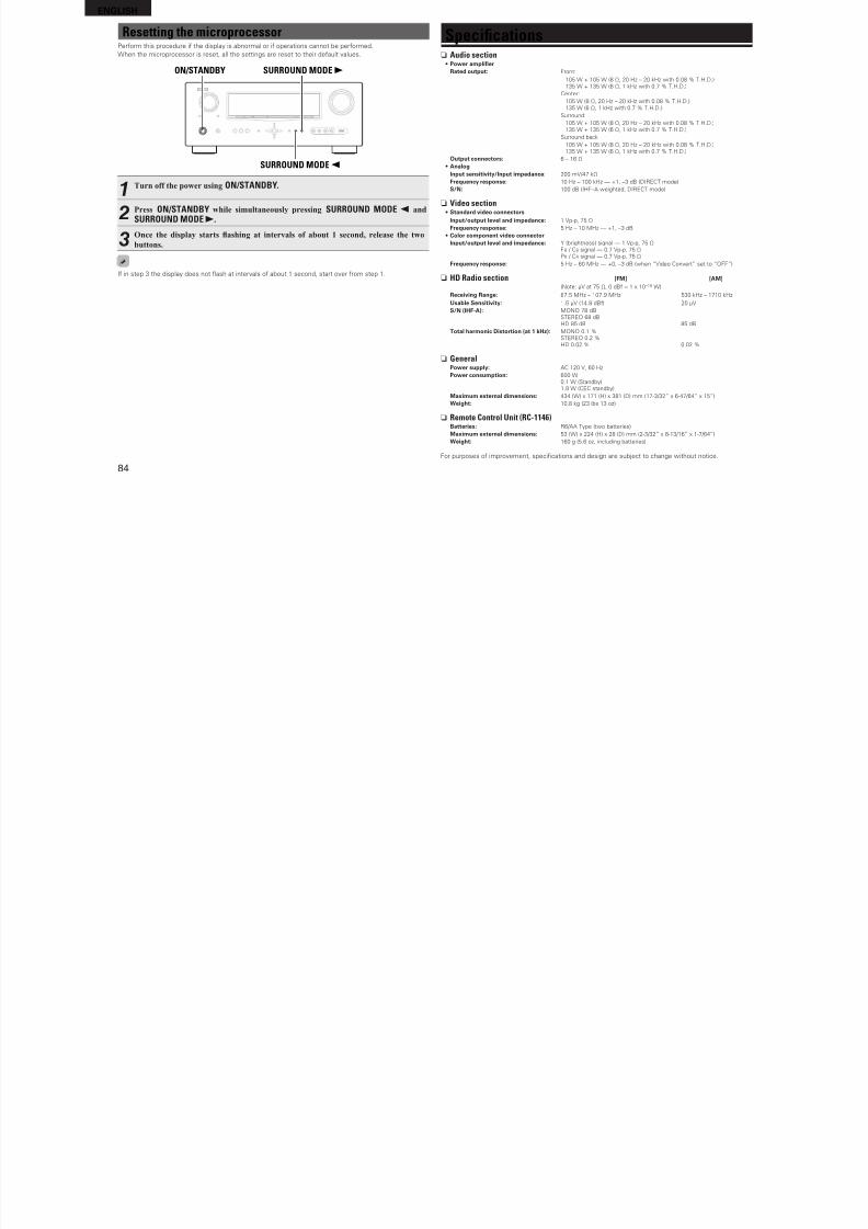
8/7/2019 IBJSC.com | I-WEB.com.vn - 953467670
http://slidepdf.com/reader/full/ibjsccom-i-webcomvn-953467670 87/92
83
B a s i c v e r s i o n
A d v a n c e d
v e r s i o n
l e v e r s i o n
I n f o r m a t i o n
output with HDMI
connection.
• When outputting HDMI audi o rom the speakers, set “HDMI
Audio Out” on the menu to “AMP”.
• When outputting HDMI audio rom a TV, set “HDMI Audio Out”
on the menu to “TV”.
60
60
No video is
output with HDMI
connection.
• Check the connection o the HDMI connectors.
• Set the input source to match the connected HDMI connector.
• Check whether the TV is compatible with copyri ght protection
(HDCP). I connected to a device not compatible with HDCP, video
will not be output correctly.
14
14, 21
14
When the ollowingoperations are
perormed on
devices compatible
with HDMI control,
the same operations
occur on this unit.
• Power ON/OFF
• Switching audio
output devices
• Adjust volume
• Switch input source
• Set “HDMI Control” on the menu to “OFF”. To operate poweronly or each device, set “Power O Control” to “OFF”.
38, 60
GHD Radio receiverH
Symptom Cause/Solution Page
Reception ails, or
there is a lot o noise
or distortion.
• Change the antenna orientation or position.
• Separate the AM loop antenna rom the unit.
• Use an FM outdoor antenna.
• Separate the antenna rom other connection cables.
19
19
19
19
GiPodH
Symptom Cause/Solution Page
iPod cannot be
played.
• Check the iPod connections.
• Plug the control dock or iPod’s AC adapter into a power outlet.
• Switch the input source to “DOCK”.
• I using an iPod connected to the USB port, incompatible iPod
types cannot be played back.
18
–
21
24
“Connection Error”
is displayed.
• Unable to communicate properly. Turn o the power to this unit,
disconnect the iPod and then reconnect it.
–
“Not Support” is
displayed.
• The iPod connected to the unit is not compatible. Please make
sure the iPod you are connecting is compatible.
• The sotware version o the connected iPod is an old one. Please
update to the latest version.
24
–
“Connection Error”
is displayed.
• The iPod is not responding. Turn o the power to this unit,
disconnect the iPod and then reconnect it.
–
memory device is
connected, “USB” is
not displayed on the
menu.
connection.
• A USB memory device not conorming to mass storage class is
connected. Connect a USB memory device conorming to mass
storage class.
• A USB memory device cannot be connected via a USB hub.
–
18
Files on a USB
memory device
cannot be played.
• Set the USB memory device ormat to “FAT16” or “FAT32”. For
details, reer to the USB memory device’s operating instructions.
• I the USB memory device is divided into multiple partitions, only
fles stored in the top partition can be played.
• The fle is recorded in an incompatible ormat. Please record it ina compatible ormat.
• This unit cannot play back fles covered by copyright protection.
–
–
–
–
The fle names
are not displayed
properly (“...”, etc.).
• Characters that cannot be displayed on this unit are replaced by
“.” (period).
22, 24
The sound quality is
poor or there is noise
during playback.
• The fle being played back has a low bit rate. –
“Connection Error”
is displayed.
• Unable to communicate properly. Turn o the power to this unit,
unplug the USB memory device and then plug it back in.
• The USB memory device is not responding. Turn o the power to
this unit, unplug the USB memory device and then plug it back in.
–
–
“Overcurrent” is
displayed.
• The USB memory device is consuming too much power. When
using a USB portable hard disk that can be powered by an ACadapter, connect its AC adapter.
–
GRemote control unitH
Symptom Cause/Solution Page
The set cannot be
operated with the
remote control unit.
• Batteries are worn out. Replace with new batteries.
• Operate the remote control unit within a distance o about 23 t /
7 m rom this unit and at an angle o within 30°.
• Remove any obstacle between this unit and the remote control
unit.
• Insert the batteries in the proper direction, checking the q and
w marks.
• The set’s remote control sensor is exposed to strong light (direct
sunlight, inverter type uorescent bulb light, etc.). Move the set
to a place in which the remote control sensor will not be exposed
to strong light.
73
73
73
73
73
ENGLISH
Resetting the microprocessorPerorm this procedure i the display is abnormal or i operations cannot be perormed.
Wh th i i t ll th tti t t th i d lt l
Specicationsn A di ti
8/7/2019 IBJSC.com | I-WEB.com.vn - 953467670
http://slidepdf.com/reader/full/ibjsccom-i-webcomvn-953467670 88/92
84
When the microprocessor is reset, all the settings are reset to their deault values.
SURROUND MODE0
SURROUND MODE1ON/STANDBY
1Turn off the power using ON/STANDBY.
2Press ON/STANDBY while simultaneously pressing SURROUND MODE 0 and
SURROUND MODE 1.
3Once the display starts ashing at intervals of about 1 second, release the two
buttons.
I in step 3 the display does not ash at intervals o about 1 second, start over rom step 1.
n Audio section• Power amplifer
Rated output: Front:
105 W + 105 W (8 Ω, 20 Hz – 20 kHz with 0.08 % T.H.D.)135 W + 135 W (6 Ω, 1 kHz with 0.7 % T.H.D.)
Center:
105 W (8 Ω, 20 Hz – 20 kHz with 0.08 % T.H.D.)135 W (6 Ω, 1 kHz with 0.7 % T.H.D.)
Surround:
105 W + 105 W (8 Ω, 20 Hz – 20 kHz with 0.08 % T.H.D.)135 W + 135 W (6 Ω, 1 kHz with 0.7 % T.H.D.)
Surround back:105 W + 105 W (8 Ω, 20 Hz – 20 kHz with 0.08 % T.H.D.)135 W + 135 W (6 Ω, 1 kHz with 0.7 % T.H.D.)
Output connectors: 6 – 16 Ω
• AnalogInput sensitivity/Input impedance: 200 mV/47 kΩ
Frequency response: 10 Hz – 100 kHz — +1, –3 dB (DIRECT mode)
S/N: 100 dB (IHF–A weighted, DIRECT mode)
n Video section• Standard video connectors
Input/output level and impedance: 1 Vp-p, 75 Ω
Frequency response: 5 Hz – 10 MHz — +1, –3 dB
• Color component video connectorInput/output level and impedance: Y (brightness) signal — 1 Vp-p, 75 Ω
PB / CB signal — 0.7 Vp-p, 75 Ω
PR / CR signal — 0.7 Vp-p, 75 ΩFrequency response: 5 Hz – 60 MHz — +0, –3 dB (when “Video Convert” set to “OFF”)
n HD Radio section [FM] [AM](Note: μV at 75 Ω, 0 dB = 1 x 10 –15 W)
Receiving Range: 87.5 MHz – 107.9 MHz 530 kHz – 1710 kHz
Usable Sensitivity: 1.5 μV (14.8 dB) 20 μV
S/N (IHF-A): MONO 78 dBSTEREO 68 dBHD 85 dB 85 dB
Total harmonic Distortion (at 1 kHz): MONO 0.1 %STEREO 0.2 %HD 0.02 % 0.02 %
n GeneralPower supply: AC 120 V, 60 Hz
Power consumption: 600 W
0.1 W (Standby)1.9 W (CEC standby)
Maximum external dimensions: 434 (W) x 171 (H) x 381 (D) mm (17-3/32” x 6-47/64” x 15”)
Weight: 10.8 kg (23 lbs 13 oz)
n Remote Control Unit (RC-1146)Batteries: R6/AA Type (two batteries)
Maximum external dimensions: 53 (W) x 224 (H) x 28 (D) mm (2-3/32” x 8-13/16” x 1-7/64”)
Weight: 160 g (5.6 oz, including batteries)
For purposes o improvement, specifcations and design are subject to change without notice.
ENGLISH
S i m p l
Index
vNumerics
Channel ······························································ 62
Channel Level ····················································· 59
Characters ·························································· 45
Chroma Level ·····················································56
DRC ···································································· 52
DTS ······························································ 29, 80
DTS 96/24 ·················································· 29, 80
DTS-ES Discrete 6.1 ··································29, 80
Quick Select ····················································· 64
Status·······························································64
Input Assign ······················································· 48
Input Mode ························································· 50
8/7/2019 IBJSC.com | I-WEB.com.vn - 953467670
http://slidepdf.com/reader/full/ibjsccom-i-webcomvn-953467670 89/92
85
B a s i c
v e r s i o n
A d v a n c e d
v e r s i o n
ev e r s i o n
I n f o r m a t i o n
2.1-channel ························································· 34
2ch Direct/Stereo ··············································· 60
3D ······································································· 14
5.1-channel ··························································· 4
6.1-channel ···················································32, 33
7.1-channel ···················································32, 33
vAAccessories ·························································· 1
Adjust CH ··························································· 55Adobe RGB color / Adobe YCC601 color ···········80
AFDM ································································· 52
AM loop antenna ················································ 19
Amp Assign ························································ 57
ARC ···································································· 14
Aspect ································································ 50
Audio Adjust ······················································· 52
Audio cable ·········································5, 16, 17, 19
Audio Delay ························································ 56
Audio Setup ························································ 60
Audio/Video Adjust ············································· 51
Audyssey Auto Setup ·····································6, 36
Audyssey Dynamic EQ ·································54, 80
Audyssey Dynamic Volume ·························55, 80
Audyssey MultEQ ··································54, 70, 80Audyssey Settings ············································· 54
Auto Lip Sync ··············································· 60, 80
Auto Preset ························································ 47
Auto Setup ····················································· 6, 36
Auto Surround Mode ·········································· 61
vBBanana plug ·························································· 4
Base Curve Copy ················································55
Bass ·····························································53, 61
Bass Setting ······················································· 58
Bi-amp ································································ 35
Brightness ·························································· 56
Browse mode ···············································22, 24
vCCable
Audio cable ······································· 5, 16, 17, 19
Coaxial digital cable ·········································16
Component video cable ····························· 15, 16
HDMI cable ·················································· 5, 14
Optical cable ···············································15, 17
Speaker cable ···················································· 5
Video cable ···········································15, 16, 17
C.Image ······························································ 52
Cinema EQ ·························································52
Coaxial digital cable ············································16
Component video cable ·······························15, 16
Condensation ······················································· 2
Connection
Antenna ··························································· 19
Blu-ray Disc player ···········································14
Cable TV ···························································16
CD player ·························································19Control dock or iPod········································18
Digital camcorder ········································14, 17
Digital vi deo recorder ······································· 14
DVD player ················································· 14, 16
External control device ····································20
Game console ··················································14
HDMI ······························································· 14
iPod (USB) ························································18
Power cord ·························································5
Satellite tuner ···················································16
Set-top box ················································ 14, 16
Speaker ························································4, 33
TV··························································· 5, 14, 15
USB memory device ········································18
Contrast ······························································ 56Crossover Frequency ·········································59
C.Width ······························································ 52
vDD.Comp ······························································ 52
Decode Mode ···················································· 50
Deep Color ··················································· 14, 80
Delay Time ························································· 52
DENON original surround mode ························· 30
Dimension ·························································· 52
Dimmer ······························································ 63
Display ································································ 70
Distance ····························································· 58
DNR ···································································· 56
Dolby
Dolby Digital···············································29, 80
Dolby Digital EX ········································· 29, 80
Dolby Digital Plus ······································· 29, 80
Dolby Pro Logic II ·············································80
Dolby Pro Logic IIx ···········································80
Dolby Pro Logic IIz ····································· 32, 80
Dolby TrueHD ·············································29, 80
Downmix ···························································· 80
,
DTS-ES Matrix 6.1 ·····································29, 80
DTS-HD ······················································29, 80
DTS-HD High Resolution Audio ·······················80
DTS-HD Master Audio ····································· 80
DTS Digital Surround ·······································80
DTS Express ···················································· 80
DTS NEO:6™ Surround ·····························28, 81
Dynamic EQ ······················································· 54
Dynamic range ··················································· 81
Dynamic Volume ················································ 55
vEEect Lev. ·························································· 52
Enhancer ···························································· 56
EQ Customize ···················································· 61
Error messages (Auto Setup) ····························· 10
vFFader unction ···················································· 39
F.Height ························································53, 58
FM indoor antenna ············································· 19
Front A/B (connection) ·································32, 34
Front height speaker ····································32, 33
Front Panel ························································· 70
Front Speaker Setup ·········································· 59
vGGUI ····································································· 62
vHHDCP ··························································· 14, 81
HDMI ····························································14, 81
HDMI 1.4 ···························································· 14
HDMI Audio Out ················································ 60
HDMI cable ····················································5, 14
HDMI Control ··············································· 38, 60
HDMI Setup ······················································· 60
Headphones ······················································· 70
Height Gain ························································ 53HPF ···································································· 61
Hue ····································································· 56
v IInormation ························································· 64
Audio Input Signal ············································64
Auto Surround Mode ·······································64
HDMI Inormation ············································ 64
Preset Channel ················································ 64
p
Input Setup ························································· 46
Input signal ···················································29, 77
iPod PLAY ·························································· 25
i/p Scal er ·····························································49
vLLevel Lch ···························································· 61
Level Rch ··························································· 61
LFE ·······························································52, 81
Listening mode ·················································· 28Listening position ················································· 7
vMMAIN ZONE ················································· 41, 81
Manual EQ ························································· 55
Manual Setup ····················································· 57
Master volume display ······································· 63
Menu map ·························································· 43
Mode ·································································· 52
MP3 ···································································· 81
MPEG ································································· 81
MultEQ ······························································· 54
Mute Level ························································· 62
vOOptical cable ·················································15, 17
Option Setup ······················································ 62
Dimmer ···························································· 63
GUI··································································· 62
Quick Select Name ··········································63
Remote ID Setup ············································· 63
Remote Preset Codes ····································· 63
Setup Lock ······················································· 63
Source Delete ·················································· 62
Trigger Out ······················································· 63
Volume Control ················································ 62
Zone Rename ·················································· 63
vPPanorama ··························································· 52
Parameter Check ················································ 10
Picture Adjust ····················································· 56
Playback
Blu-ray Disc player ···········································22
CD player ························································· 22
Direct ······························································· 30
DVD player ······················································· 22
HD Radio reception ··········································25
ENGLISHiPod (Control dock or iPod) ······························22
iPod (USB) ························································ 24
MP3 ································································· 27
MPEG-4 AAC ··················································· 27
Sleep timer ·························································39
Source Delete ···················································· 62
Source Level ······················································ 51
Speaker

8/7/2019 IBJSC.com | I-WEB.com.vn - 953467670
http://slidepdf.com/reader/full/ibjsccom-i-webcomvn-953467670 90/92
86
Pure direct ······················································· 30
Standard ·························································· 28
Stereo ······························································ 30
USB memory device ········································27
WMA ······························································· 27
ZONE2 ····························································· 42
Playback Mode (Control dock or iPod) ··············51
Playback Mode (USB) ········································· 51
Power O Control ·············································· 60
Power On Level ·················································62Preset codes ················································ 63, 65
Preset Name ······················································ 48
Preset Skip ························································· 47
Presetting radio stations ···································· 26
Progressive ························································ 81
Progressive Mode ·············································· 50
Protection circuit ················································ 81
vQQuick select ·················································40, 42
Quick Select Name ············································63
vRRear panel ·························································· 71
REC OUT mode ·················································· 40Reerence Level Oset ······································ 54
Remote control unit ·····································65, 72
Inserting the batteries ······································ 73
Operating components ···································· 68
Registering Preset Codes ································ 65
Remote ID Setup ··············································· 63
Remote mode ·············································· 22, 24
Remote Preset Codes ········································ 63
Rename ······························································ 50
Repeat ································································ 51
Resetting the microprocessor ····························84
Resolution ·························································· 50
RESTORER ························································· 56
RGB Range ························································· 60
Room Size ·························································· 52
vSSampling requency ··········································· 81
S.Back ·························································· 53, 58
Screensaver ······················································· 62
Selecting the input source ································· 21
Setup Lock ························································· 63
Shue ································································ 51
p
Connect ······················································· 4, 33
Install ··························································· 4, 32
Set up ·························································· 6, 36
Speaker cable ······················································· 5
Speaker Confg. ·················································· 57
Speaker impedance ········································4, 81
Speaker Setup ····················································57
Standby Source ·················································· 60
Subwooer ·························································· 53
Subwooer setting ················································7Surround back speaker ·································32, 33
Surround Mode ············································ 28, 75
Surround Parameter ···········································52
sYCC601 color ···················································· 81
vTTone ··································································· 53
Tone Control ·······················································53
Trademark ·························································· 74
Treble ··························································· 53, 61
Trigger Out ·························································63
Turn o power (standby) ···································· 11
Turn on power ······················································6
vVVideo ·································································· 49
Video cable ············································· 15, 16, 17
Video conversion ················································ 13
Video Convert ····················································· 49
Video Mode ························································49
Video Select ······················································· 49
Volume Control ·················································· 62
Volume Level ····················································· 62
Volume Limit ······················································ 62
vWWMA ·································································· 81
vXx.v.Color ····························································· 81
vZZONE2 ····················································41, 70, 81
ZONE2 Setup ·····················································61
Zone Rename ·····················································63

8/7/2019 IBJSC.com | I-WEB.com.vn - 953467670
http://slidepdf.com/reader/full/ibjsccom-i-webcomvn-953467670 91/92

8/7/2019 IBJSC.com | I-WEB.com.vn - 953467670
http://slidepdf.com/reader/full/ibjsccom-i-webcomvn-953467670 92/92