Embed Size (px)
Citation preview
ibm.com/redbooks Redpaper
Front cover
IBM Flex System Networking in an Enterprise Data Center
Ilya KrutovMatthew Slavin
Describes evolution of enterprise data center networking infrastructure
Describes networking architecture and portfolio
Provides in-depth network planning considerations

International Technical Support Organization
IBM Flex System Networking in an Enterprise Data Center
August 2013
REDP-4834-01

© Copyright International Business Machines Corporation, 2012, 2013. All rights reserved.Note to U.S. Government Users Restricted Rights -- Use, duplication or disclosure restricted by GSA ADP ScheduleContract with IBM Corp.
Second Edition (August 2013)
This edition applies to IBM Flex System.
Contents
Notices . . . . . . . . . . . . . . . . . . . . . . . . . . . . . . . . . . . . . . . . . . . . . . . . . . . . . . . . . . . . . . . . . .vTrademarks . . . . . . . . . . . . . . . . . . . . . . . . . . . . . . . . . . . . . . . . . . . . . . . . . . . . . . . . . . . . . . vi
Preface . . . . . . . . . . . . . . . . . . . . . . . . . . . . . . . . . . . . . . . . . . . . . . . . . . . . . . . . . . . . . . . . . viiAuthors. . . . . . . . . . . . . . . . . . . . . . . . . . . . . . . . . . . . . . . . . . . . . . . . . . . . . . . . . . . . . . . . . viiiNow you can become a published author, too! . . . . . . . . . . . . . . . . . . . . . . . . . . . . . . . . . . . ixComments welcome. . . . . . . . . . . . . . . . . . . . . . . . . . . . . . . . . . . . . . . . . . . . . . . . . . . . . . . . ixStay connected to IBM Redbooks . . . . . . . . . . . . . . . . . . . . . . . . . . . . . . . . . . . . . . . . . . . . . ix
Chapter 1. Data center networking overview . . . . . . . . . . . . . . . . . . . . . . . . . . . . . . . . . . 11.1 Data center components . . . . . . . . . . . . . . . . . . . . . . . . . . . . . . . . . . . . . . . . . . . . . . . . . 21.2 Evolution of the data center network design . . . . . . . . . . . . . . . . . . . . . . . . . . . . . . . . . . 4
1.2.1 Traditional network design . . . . . . . . . . . . . . . . . . . . . . . . . . . . . . . . . . . . . . . . . . . 51.2.2 Network design with server virtualization . . . . . . . . . . . . . . . . . . . . . . . . . . . . . . . . 61.2.3 Network design with server virtualization and converged networking. . . . . . . . . . . 8
1.3 Network virtualization . . . . . . . . . . . . . . . . . . . . . . . . . . . . . . . . . . . . . . . . . . . . . . . . . . 111.4 Conclusions. . . . . . . . . . . . . . . . . . . . . . . . . . . . . . . . . . . . . . . . . . . . . . . . . . . . . . . . . . 12
Chapter 2. IBM Flex System networking architecture and portfolio. . . . . . . . . . . . . . . 152.1 Enterprise Chassis I/O architecture . . . . . . . . . . . . . . . . . . . . . . . . . . . . . . . . . . . . . . . 162.2 IBM Flex System Ethernet I/O modules . . . . . . . . . . . . . . . . . . . . . . . . . . . . . . . . . . . . 19
2.2.1 IBM Flex System EN2092 1Gb Ethernet Scalable Switch . . . . . . . . . . . . . . . . . . 192.2.2 IBM Flex System EN4091 10Gb Ethernet Pass-thru . . . . . . . . . . . . . . . . . . . . . . 232.2.3 IBM Flex System Fabric EN4093 and EN4093R 10Gb Scalable Switches . . . . . 242.2.4 IBM Flex System Fabric CN4093 10Gb Converged Scalable Switch . . . . . . . . . . 282.2.5 IBM Flex System Fabric SI4093 System Interconnect Module . . . . . . . . . . . . . . . 342.2.6 IBM Flex System EN6131 40Gb Ethernet Switch . . . . . . . . . . . . . . . . . . . . . . . . . 382.2.7 I/O modules and cables . . . . . . . . . . . . . . . . . . . . . . . . . . . . . . . . . . . . . . . . . . . . 41
2.3 IBM Flex System Ethernet adapters . . . . . . . . . . . . . . . . . . . . . . . . . . . . . . . . . . . . . . . 422.3.1 IBM Flex System CN4054 10Gb Virtual Fabric Adapter . . . . . . . . . . . . . . . . . . . . 422.3.2 IBM Flex System CN4058 8-port 10Gb Converged Adapter . . . . . . . . . . . . . . . . 442.3.3 IBM Flex System EN2024 4-port 1Gb Ethernet Adapter. . . . . . . . . . . . . . . . . . . . 452.3.4 IBM Flex System EN4054 4-port 10Gb Ethernet Adapter. . . . . . . . . . . . . . . . . . . 472.3.5 IBM Flex System EN4132 2-port 10Gb Ethernet Adapter. . . . . . . . . . . . . . . . . . . 482.3.6 IBM Flex System EN4132 2-port 10Gb RoCE Adapter. . . . . . . . . . . . . . . . . . . . . 492.3.7 IBM Flex System EN6132 2-port 40Gb Ethernet Adapter. . . . . . . . . . . . . . . . . . . 51
Chapter 3. IBM Flex System data center network design basics . . . . . . . . . . . . . . . . . 553.1 Choosing the Ethernet switch I/O module. . . . . . . . . . . . . . . . . . . . . . . . . . . . . . . . . . . 563.2 Virtual local area networks . . . . . . . . . . . . . . . . . . . . . . . . . . . . . . . . . . . . . . . . . . . . . . 573.3 Scalability and performance . . . . . . . . . . . . . . . . . . . . . . . . . . . . . . . . . . . . . . . . . . . . . 593.4 High availability . . . . . . . . . . . . . . . . . . . . . . . . . . . . . . . . . . . . . . . . . . . . . . . . . . . . . . . 60
3.4.1 Highly available topologies . . . . . . . . . . . . . . . . . . . . . . . . . . . . . . . . . . . . . . . . . . 623.4.2 Spanning Tree . . . . . . . . . . . . . . . . . . . . . . . . . . . . . . . . . . . . . . . . . . . . . . . . . . . 653.4.3 Link aggregation . . . . . . . . . . . . . . . . . . . . . . . . . . . . . . . . . . . . . . . . . . . . . . . . . . 663.4.4 NIC teaming . . . . . . . . . . . . . . . . . . . . . . . . . . . . . . . . . . . . . . . . . . . . . . . . . . . . . 683.4.5 Trunk failover . . . . . . . . . . . . . . . . . . . . . . . . . . . . . . . . . . . . . . . . . . . . . . . . . . . . 693.4.6 VRRP . . . . . . . . . . . . . . . . . . . . . . . . . . . . . . . . . . . . . . . . . . . . . . . . . . . . . . . . . . 70
3.5 FCoE capabilities . . . . . . . . . . . . . . . . . . . . . . . . . . . . . . . . . . . . . . . . . . . . . . . . . . . . . 71
© Copyright IBM Corp. 2013. All rights reserved. iii
3.6 Virtual Fabric vNIC solution capabilities . . . . . . . . . . . . . . . . . . . . . . . . . . . . . . . . . . . . 723.6.1 Virtual Fabric mode vNIC . . . . . . . . . . . . . . . . . . . . . . . . . . . . . . . . . . . . . . . . . . . 733.6.2 Switch-independent mode vNIC . . . . . . . . . . . . . . . . . . . . . . . . . . . . . . . . . . . . . . 75
3.7 Unified Fabric Port feature . . . . . . . . . . . . . . . . . . . . . . . . . . . . . . . . . . . . . . . . . . . . . . 763.8 Easy Connect concept . . . . . . . . . . . . . . . . . . . . . . . . . . . . . . . . . . . . . . . . . . . . . . . . . 783.9 Stacking feature . . . . . . . . . . . . . . . . . . . . . . . . . . . . . . . . . . . . . . . . . . . . . . . . . . . . . . 793.10 Openflow support . . . . . . . . . . . . . . . . . . . . . . . . . . . . . . . . . . . . . . . . . . . . . . . . . . . . 813.11 802.1Qbg Edge Virtual Bridge support . . . . . . . . . . . . . . . . . . . . . . . . . . . . . . . . . . . . 823.12 SPAR feature . . . . . . . . . . . . . . . . . . . . . . . . . . . . . . . . . . . . . . . . . . . . . . . . . . . . . . . 823.13 Management . . . . . . . . . . . . . . . . . . . . . . . . . . . . . . . . . . . . . . . . . . . . . . . . . . . . . . . . 83
3.13.1 Management tools and their capabilities. . . . . . . . . . . . . . . . . . . . . . . . . . . . . . . 853.14 Summary and conclusions . . . . . . . . . . . . . . . . . . . . . . . . . . . . . . . . . . . . . . . . . . . . . 86
Abbreviations and acronyms . . . . . . . . . . . . . . . . . . . . . . . . . . . . . . . . . . . . . . . . . . . . . . 89
Related publications . . . . . . . . . . . . . . . . . . . . . . . . . . . . . . . . . . . . . . . . . . . . . . . . . . . . . 91IBM Redbooks . . . . . . . . . . . . . . . . . . . . . . . . . . . . . . . . . . . . . . . . . . . . . . . . . . . . . . . . . . . 91Help from IBM . . . . . . . . . . . . . . . . . . . . . . . . . . . . . . . . . . . . . . . . . . . . . . . . . . . . . . . . . . . 91
iv IBM Flex System Networking in an Enterprise Data Center

Notices
This information was developed for products and services offered in the U.S.A.
IBM may not offer the products, services, or features discussed in this document in other countries. Consult your local IBM representative for information on the products and services currently available in your area. Any reference to an IBM product, program, or service is not intended to state or imply that only that IBM product, program, or service may be used. Any functionally equivalent product, program, or service that does not infringe any IBM intellectual property right may be used instead. However, it is the user's responsibility to evaluate and verify the operation of any non-IBM product, program, or service.
IBM may have patents or pending patent applications covering subject matter described in this document. The furnishing of this document does not give you any license to these patents. You can send license inquiries, in writing, to: IBM Director of Licensing, IBM Corporation, North Castle Drive, Armonk, NY 10504-1785 U.S.A.
The following paragraph does not apply to the United Kingdom or any other country where such provisions are inconsistent with local law: INTERNATIONAL BUSINESS MACHINES CORPORATION PROVIDES THIS PUBLICATION “AS IS” WITHOUT WARRANTY OF ANY KIND, EITHER EXPRESS OR IMPLIED, INCLUDING, BUT NOT LIMITED TO, THE IMPLIED WARRANTIES OF NON-INFRINGEMENT, MERCHANTABILITY OR FITNESS FOR A PARTICULAR PURPOSE. Some states do not allow disclaimer of express or implied warranties in certain transactions, therefore, this statement may not apply to you.
This information could include technical inaccuracies or typographical errors. Changes are periodically made to the information herein; these changes will be incorporated in new editions of the publication. IBM may make improvements and/or changes in the product(s) and/or the program(s) described in this publication at any time without notice.
Any references in this information to non-IBM websites are provided for convenience only and do not in any manner serve as an endorsement of those websites. The materials at those websites are not part of the materials for this IBM product and use of those websites is at your own risk.
IBM may use or distribute any of the information you supply in any way it believes appropriate without incurring any obligation to you.
Any performance data contained herein was determined in a controlled environment. Therefore, the results obtained in other operating environments may vary significantly. Some measurements may have been made on development-level systems and there is no guarantee that these measurements will be the same on generally available systems. Furthermore, some measurements may have been estimated through extrapolation. Actual results may vary. Users of this document should verify the applicable data for their specific environment.
Information concerning non-IBM products was obtained from the suppliers of those products, their published announcements or other publicly available sources. IBM has not tested those products and cannot confirm the accuracy of performance, compatibility or any other claims related to non-IBM products. Questions on the capabilities of non-IBM products should be addressed to the suppliers of those products.
This information contains examples of data and reports used in daily business operations. To illustrate them as completely as possible, the examples include the names of individuals, companies, brands, and products. All of these names are fictitious and any similarity to the names and addresses used by an actual business enterprise is entirely coincidental.
COPYRIGHT LICENSE:
This information contains sample application programs in source language, which illustrate programming techniques on various operating platforms. You may copy, modify, and distribute these sample programs in any form without payment to IBM, for the purposes of developing, using, marketing or distributing application programs conforming to the application programming interface for the operating platform for which the sample programs are written. These examples have not been thoroughly tested under all conditions. IBM, therefore, cannot guarantee or imply reliability, serviceability, or function of these programs.
© Copyright IBM Corp. 2013. All rights reserved. v
Trademarks
IBM, the IBM logo, and ibm.com are trademarks or registered trademarks of International Business Machines Corporation in the United States, other countries, or both. These and other IBM trademarked terms are marked on their first occurrence in this information with the appropriate symbol (® or ™), indicating US registered or common law trademarks owned by IBM at the time this information was published. Such trademarks may also be registered or common law trademarks in other countries. A current list of IBM trademarks is available on the Web at http://www.ibm.com/legal/copytrade.shtml
The following terms are trademarks of the International Business Machines Corporation in the United States, other countries, or both:
Blade Network Technologies®BladeCenter®DB2®IBM®IBM Flex System™
IBM Flex System Manager™Power Systems™RackSwitch™Redbooks®Redpaper™
Redbooks (logo) ®System x®VMready®
The following terms are trademarks of other companies:
Evolution, and Kenexa device are trademarks or registered trademarks of Kenexa, an IBM Company.
Linux is a trademark of Linus Torvalds in the United States, other countries, or both.
Microsoft, Windows, and the Windows logo are trademarks of Microsoft Corporation in the United States, other countries, or both.
Other company, product, or service names may be trademarks or service marks of others.
vi IBM Flex System Networking in an Enterprise Data Center
Preface
Networking in data centers today is undergoing a transition from a discrete traditional model to a more flexible, optimized model or the “smarter” model. Clients are looking to support more workloads with decreasing or flat IT budgets. The network architecture on the recently announced IBM® Flex System platform is designed to address the key challenges clients are facing today in their data centers.
IBM Flex System™, a new category of computing and the next generation of Smarter Computing, offers intelligent workload deployment and management for maximum business agility. This chassis delivers high-speed performance complete with integrated servers, storage, and networking for multi-chassis management in data center compute environments. Its flexible design can meet the needs of varying workloads with independently scalable IT resource pools for higher usage and lower cost per workload. Although increased security and resiliency protect vital information and promote maximum uptime, the integrated, easy-to-use management system reduces setup time and complexity, which provides a quicker path to ROI.
The network architecture on this platform includes the following key attributes:
� Integrated:
– Efficient integrated management as part of the management appliance
– Move from physical network management to logical network management in a virtualized environment
� Automated
Seamless provisioning, management, and deployment of physical and virtual network parameters that use tools such as IBM Fabric Manager, IBM Distributed Virtual Switch 5000V, and IBM VMready®
� Optimized:
– Creation of a flat logical network so there are fewer elements to manage
– Reduced cost and complexity by using IBM Virtual Fabric and I/O convergence
– Reduced risk and cost by using scalable switches that can provide port and bandwidth flexibility
The purpose of this IBM Redpaper™ publication is to describe how the data center network design approach is transformed with the introduction of new IBM Flex System platform. This paper explains how the data center networking infrastructure has evolved over time to address rising data center challenges in resource usage, performance, availability, security, provisioning, operational efficiency, and management. It describes IBM Flex System networking architecture and the product portfolio capabilities. It also provides recommendations on how to successfully plan IBM Flex System networking deployment by choosing the most appropriate network technologies to achieve availability, performance, security, operational efficiency, and management goals in a virtualized data center environment.
This IBM Redpaper publication is intended for anyone who wants to learn more about IBM Flex System networking components and solutions.
© Copyright IBM Corp. 2013. All rights reserved. vii

Authors
This paper was produced by a team of specialists from around the world who work at the International Technical Support Organization, Raleigh Center.
Ilya Krutov is a Project Leader at the ITSO Center in Raleigh and has been with IBM since 1998. Before he joined the ITSO, Ilya served in IBM as a Run Rate Team Leader, Portfolio Manager, Brand Manager, Technical Sales Specialist, and Certified Instructor. Ilya has expertise in IBM System x®, BladeCenter®, and Flex System products; server operating systems; and networking solutions. He has authored over 130 books, papers, Product Guides, and Solution Guides. He has a bachelor’s degree in Computer Engineering from the Moscow Engineering and Physics Institute.
Matthew Slavin is a Consulting Systems Engineer for IBM Systems Networking, based out of Tulsa, Oklahoma. He has a background of over 30 years of hands-on systems and network design, installation, and troubleshooting. Most recently, he has focused on data center networking where he is leading client efforts in adopting new and potently game-changing technologies into their day-to-day operations. Matt joined IBM through the acquisition of Blade Network Technologies®, and worked at some of the top systems and networking companies in the world.
Thanks to the following people for their contributions to this project:
From International Technical Support Organization, Raleigh Center:
� Kevin Barnes� Tamikia Barrow� Ella Buslovich� Mary Comianos� Shari Deiana� Cheryl Gera� David Watts
From IBM:
� Mike Easterly� Scott Irwin� Shekhar Mishra� Larkland Morley� Heather Richardson� Hector Sanchez� Phil Searles� Thomas Zukowski
viii IBM Flex System Networking in an Enterprise Data Center
Now you can become a published author, too!
Here’s an opportunity to spotlight your skills, grow your career, and become a published author — all at the same time! Join an ITSO residency project and help write a book in your area of expertise, while honing your experience using leading-edge technologies. Your efforts help to increase product acceptance and customer satisfaction, as you expand your network of technical contacts and relationships. Residencies run from two to six weeks in length, and you can participate either in person or as a remote resident working from your home base.
Find out more about the residency program, browse the residency index, and apply online at:
http://www.ibm.com/redbooks/residencies.html
Comments welcome
Your comments are important to us!
We want our papers to be as helpful as possible. Send us your comments about this paper or other IBM Redbooks® publications in one of the following ways:
� Use the online Contact us review Redbooks form found at:
http://www.ibm.com/redbooks
� Send your comments in an email to:
http://[email protected]
� Mail your comments to:
IBM Corporation, International Technical Support OrganizationDept. HYTD Mail Station P0992455 South RoadPoughkeepsie, NY 12601-5400
Stay connected to IBM Redbooks
� Find us on Facebook:
http://www.facebook.com/IBMRedbooks
� Follow us on Twitter:
http://twitter.com/ibmredbooks
� Look for us on LinkedIn:
http://www.linkedin.com/groups?home=&gid=2130806
� Explore new Redbooks publications, residencies, and workshops with the IBM Redbooks weekly newsletter:
https://www.redbooks.ibm.com/Redbooks.nsf/subscribe?OpenForm
� Stay current on recent Redbooks publications with RSS Feeds:
http://www.redbooks.ibm.com/rss.html
Preface ix

x IBM Flex System Networking in an Enterprise Data Center
Chapter 1. Data center networking overview
The networking infrastructure in a data center has evolved with the adoption of data center consolidation and server virtualization strategies. This chapter describes the evolution trends in data centers and the effect those trends have on the networking infrastructure.
This chapter includes the following topics:
� Data center components� Evolution of the data center network design� Network virtualization� Conclusions
1
© Copyright IBM Corp. 2013. All rights reserved. 1
1.1 Data center components
A typical enterprise data center uses the following major components:
� Applications
Data center applications represent core business applications that provide services to the internal and external users; for example, customer relationship management system (CRM) for the employees and online ordering system for the clients.
� Software infrastructure services
Software infrastructure supports applications by providing utility services to them, such as hypervisors to run applications in virtual machines, databases to work with application data, High Availability (HA) clusters to ensure 24x7 application availability, and web-based interfaces to allow user interaction with the system. Providing security to the data center applications and enabling efficient data center systems management are also parts of the software infrastructure services.
� Hardware infrastructure
Hardware infrastructure is responsible for hosting all applications and infrastructure services and establishing effective and secure communications between them. The hardware infrastructure includes servers, storage, local area networks (LAN), and storage area networks (SAN).
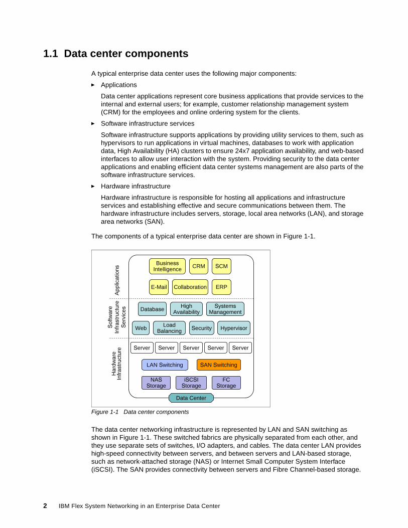
The components of a typical enterprise data center are shown in Figure 1-1.
Figure 1-1 Data center components
The data center networking infrastructure is represented by LAN and SAN switching as shown in Figure 1-1. These switched fabrics are physically separated from each other, and they use separate sets of switches, I/O adapters, and cables. The data center LAN provides high-speed connectivity between servers, and between servers and LAN-based storage, such as network-attached storage (NAS) or Internet Small Computer System Interface (iSCSI). The SAN provides connectivity between servers and Fibre Channel-based storage.
Har
dwar
e In
fras
truc
ture
Sof
twar
eIn
fras
truc
ture
Ser
vice
sA
pplic
atio
ns
ERP
Web
NAS Storage
Data Center
SAN Switching
Server
LAN Switching
FCStorage
iSCSI Storage
Security
High Availability
Load Balancing
Systems ManagementDatabase
Hypervisor
CRM
E-Mail Collaboration
Business Intelligence
Server ServerServer Server
SCM
2 IBM Flex System Networking in an Enterprise Data Center
In this section, we focus on a data center LAN networking design approach and SAN topics that are directly related to the LAN infrastructure, for example, converged networks. Fundamental data center network design requirements include the following features:
� Reliability, availability, and serviceability (RAS)
RAS features define how infrequently the network experiences faults (reliability), how these faults affect the functionality of the network (availability), and how efficiently and non-disruptively these faults are repaired (serviceability).
� Scalability and performance
The network must have sufficient link bandwidth and switching throughput to handle the planned amounts and patterns of data traffic to avoid network congestion, a sufficient number of ports and address spaces to provide server and inter-switch connectivity, quality of service (QoS) prioritization to handle delay-sensitive traffic, and the ability to support the growth of network workloads in a cost-efficient “pay as you grow” manner.
� Security
Network security rules define permissions to access data, services, or devices within the network. They include authentication (who can access), authorization (what the user can do), and accounting (monitoring and logging of security violations) procedures.
� Systems management
Network management provides a unified centralized interface to discover, configure, monitor, and troubleshoot network devices and topologies.
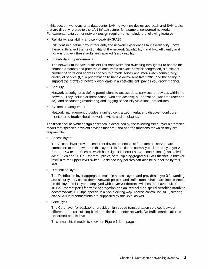
The traditional network design approach is described by the following three-layer hierarchical model that specifies physical devices that are used and the functions for which they are responsible:
� Access layer
The Access layer provides endpoint device connections; for example, servers are connected to the network on this layer. This function is normally performed by Layer 2 Ethernet switches. Such a switch has Gigabit Ethernet server connections (also called downlinks) and 10 Gb Ethernet uplinks, or multiple aggregated 1 Gb Ethernet uplinks (or trunks) to the upper layer switch. Basic security policies can also be supported by this level.
� Distribution layer
The Distribution layer aggregates multiple access layers and provides Layer 3 forwarding and security services to them. Network policies and traffic manipulation are implemented on this layer. This layer is deployed with Layer 3 Ethernet switches that have multiple 10 Gb Ethernet ports for traffic aggregation and an internal high-speed switching matrix to accommodate 10 Gbps speeds in a non-blocking way. Access control list (ACL) filtering and VLAN interconnections are supported by this level as well.
� Core layer
The Core layer (or backbone) provides high-speed transportation services between different parts (or building blocks) of the data center network. No traffic manipulation is performed on this level.
This hierarchical model is shown in Figure 1-2 on page 4.
Chapter 1. Data center networking overview 3
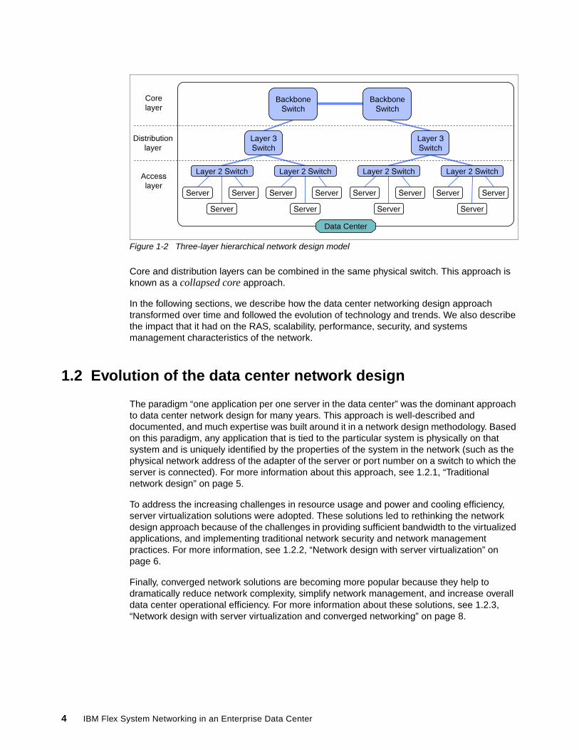
Figure 1-2 Three-layer hierarchical network design model
Core and distribution layers can be combined in the same physical switch. This approach is known as a collapsed core approach.
In the following sections, we describe how the data center networking design approach transformed over time and followed the evolution of technology and trends. We also describe the impact that it had on the RAS, scalability, performance, security, and systems management characteristics of the network.
1.2 Evolution of the data center network design
The paradigm “one application per one server in the data center” was the dominant approach to data center network design for many years. This approach is well-described and documented, and much expertise was built around it in a network design methodology. Based on this paradigm, any application that is tied to the particular system is physically on that system and is uniquely identified by the properties of the system in the network (such as the physical network address of the adapter of the server or port number on a switch to which the server is connected). For more information about this approach, see 1.2.1, “Traditional network design” on page 5.
To address the increasing challenges in resource usage and power and cooling efficiency, server virtualization solutions were adopted. These solutions led to rethinking the network design approach because of the challenges in providing sufficient bandwidth to the virtualized applications, and implementing traditional network security and network management practices. For more information, see 1.2.2, “Network design with server virtualization” on page 6.
Finally, converged network solutions are becoming more popular because they help to dramatically reduce network complexity, simplify network management, and increase overall data center operational efficiency. For more information about these solutions, see 1.2.3, “Network design with server virtualization and converged networking” on page 8.
Distribution layer
Accesslayer
Corelayer
Data Center
Server
Server
Server Server
Server
Server Server
Server
Server Server
Server
Server
Backbone Switch
Backbone Switch
Layer 2 Switch
Layer 3 Switch
Layer 2 Switch Layer 2 Switch
Layer 3 Switch
Layer 2 Switch
4 IBM Flex System Networking in an Enterprise Data Center
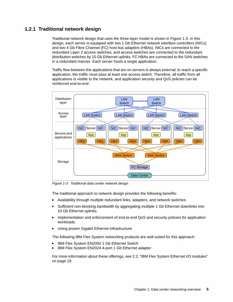
1.2.1 Traditional network design
Traditional network design that uses the three-layer model is shown in Figure 1-3. In this design, each server is equipped with two 1 Gb Ethernet network interface controllers (NICs) and two 4 Gb Fibre Channel (FC) host bus adapters (HBAs). NICs are connected to the redundant Layer 2 access switches, and access switches are connected to the redundant distribution switches by 10 Gb Ethernet uplinks. FC HBAs are connected to the SAN switches in a redundant manner. Each server hosts a single application.
Traffic flow between the applications that are on servers is always external; to reach a specific application, the traffic must pass at least one access switch. Therefore, all traffic from all applications is visible to the network, and application security and QoS policies can be reinforced end-to-end.
Figure 1-3 Traditional data center network design
The traditional approach to network design provides the following benefits:
� Availability through multiple redundant links, adapters, and network switches.
� Sufficient non-blocking bandwidth by aggregating multiple 1 Gb Ethernet downlinks into 10 Gb Ethernet uplinks.
� Implementation and enforcement of end-to-end QoS and security policies for application workloads.
� Using proven Gigabit Ethernet infrastructure.
The following IBM Flex System networking products are well-suited for this approach:
� IBM Flex System EN2092 1 Gb Ethernet Switch� IBM Flex System EN2024 4-port 1 Gb Ethernet adapter
For more information about these offerings, see 2.2, “IBM Flex System Ethernet I/O modules” on page 19.
Access layer
Distribution layer
Servers andapplications
Server
Storage
ServerServer Server
Data Center
NIC NIC
App
NIC NIC
App
NIC NIC
App
NIC NIC
App
LAN Switch
LAN SwitchLAN Switch LAN SwitchLAN Switch
LAN Switch
SAN Switch SAN Switch
FC Storage
HBA HBAHBA HBAHBA HBA HBA HBA
Chapter 1. Data center networking overview 5
Although this approach might be cost-effective for small network deployments, it is a questionable approach in large-scale implementations. It has limited scalability and complicated systems management because of the need to maintain and manage multiple network links and devices. In addition, the higher the number of components that are used to build infrastructure statistically lead to a higher number of network failures that is sacrificing availability and increasing the total cost of ownership (TCO).
In addition, with a 1:1 application-to-server approach, many servers are underused, which leads to wasted compute power and inefficient electrical power consumption and cooling. Although server virtualization technology addressed these issues, the technology also added new questions to the implementation of security and network management policies.
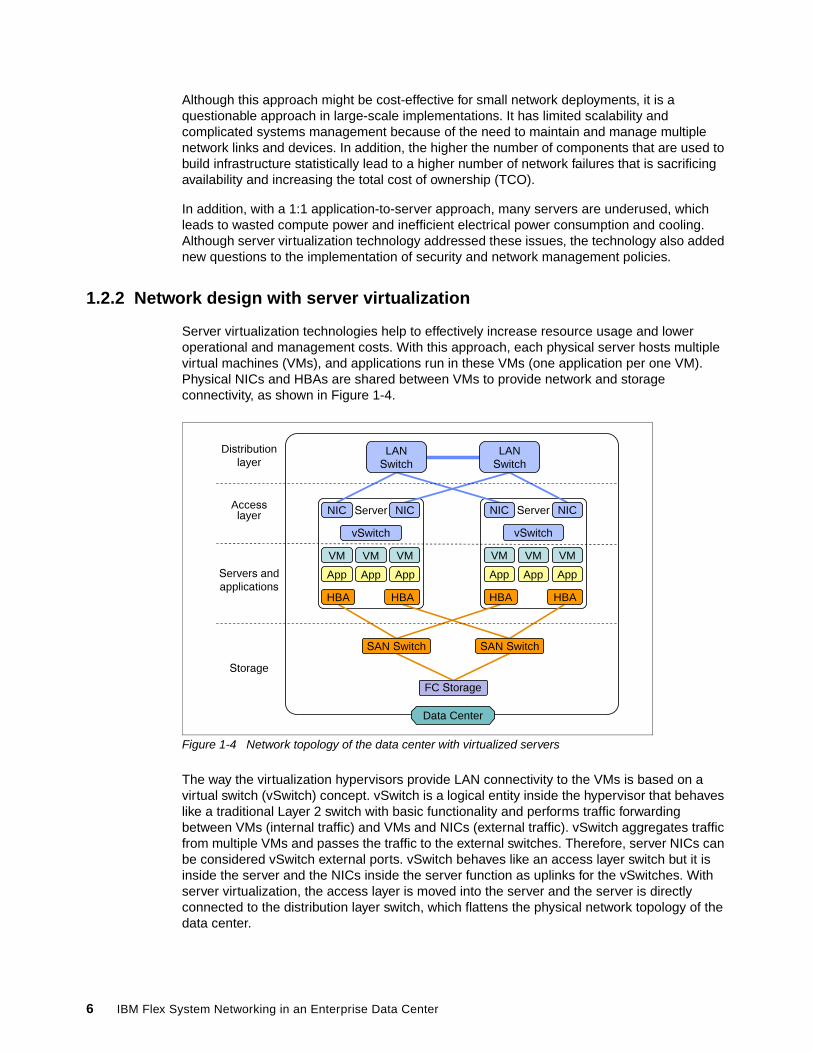
1.2.2 Network design with server virtualization
Server virtualization technologies help to effectively increase resource usage and lower operational and management costs. With this approach, each physical server hosts multiple virtual machines (VMs), and applications run in these VMs (one application per one VM). Physical NICs and HBAs are shared between VMs to provide network and storage connectivity, as shown in Figure 1-4.
Figure 1-4 Network topology of the data center with virtualized servers
The way the virtualization hypervisors provide LAN connectivity to the VMs is based on a virtual switch (vSwitch) concept. vSwitch is a logical entity inside the hypervisor that behaves like a traditional Layer 2 switch with basic functionality and performs traffic forwarding between VMs (internal traffic) and VMs and NICs (external traffic). vSwitch aggregates traffic from multiple VMs and passes the traffic to the external switches. Therefore, server NICs can be considered vSwitch external ports. vSwitch behaves like an access layer switch but it is inside the server and the NICs inside the server function as uplinks for the vSwitches. With server virtualization, the access layer is moved into the server and the server is directly connected to the distribution layer switch, which flattens the physical network topology of the data center.
Access layer
Distribution layer
Servers andapplications
Storage
Data Center
Server Server
vSwitch
VM
App
VM
App
VM
App
SAN Switch SAN Switch
FC Storage
vSwitch
VM
App
VM
App
VM
App
LAN Switch
LAN Switch
NIC NIC NIC NIC
HBA HBA HBA HBA
6 IBM Flex System Networking in an Enterprise Data Center
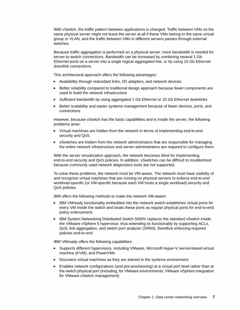
With vSwitch, the traffic pattern between applications is changed. Traffic between VMs on the same physical server might not leave the server at all if these VMs belong to the same virtual group or VLAN, and the traffic between VMs in different servers passes through external switches.
Because traffic aggregation is performed on a physical server, more bandwidth is needed for server-to-switch connections. Bandwidth can be increased by combining several 1 Gb Ethernet ports on a server into a single logical aggregated link, or by using 10 Gb Ethernet downlink connections.
This architectural approach offers the following advantages:
� Availability through redundant links, I/O adapters, and network devices
� Better reliability compared to traditional design approach because fewer components are used to build the network infrastructure
� Sufficient bandwidth by using aggregated 1 Gb Ethernet or 10 Gb Ethernet downlinks
� Better scalability and easier systems management because of fewer devices, ports, and connections
However, because vSwitch has the basic capabilities and is inside the server, the following problems arise:
� Virtual machines are hidden from the network in terms of implementing end-to-end security and QoS.
� vSwitches are hidden from the network administrators that are responsible for managing the entire network infrastructure and server administrators are required to configure them.
With the server virtualization approach, the network becomes blind for implementing end-to-end security and QoS policies. In addition, vSwitches can be difficult to troubleshoot because commonly used network diagnostics tools are not supported.
To solve these problems, the network must be VM-aware. The network must have visibility of and recognize virtual machines that are running on physical servers to enforce end-to-end workload-specific (or VM-specific because each VM hosts a single workload) security and QoS policies.
IBM offers the following methods to make the network VM-aware:
� IBM VMready functionality embedded into the network switch establishes virtual ports for every VM inside the switch and treats these ports as regular physical ports for end-to-end policy enforcement.
� IBM System Networking Distributed Switch 5000V replaces the standard vSwitch inside the VMware vSphere 5 hypervisor, thus extending its functionality by supporting ACLs, QoS, link aggregation, and switch port analyzer (SPAN), therefore enforcing required policies end-to-end
IBM VMready offers the following capabilities:
� Supports different hypervisors, including VMware, Microsoft Hyper-V, kernel-based virtual machine (KVM), and PowerVMs
� Discovers virtual machines as they are started in the systems environment
� Enables network configurations (and pre-provisioning) at a virtual port level rather than at the switch physical port (including, for VMware environments, VMware vSphere integration for VMware vSwitch management)
Chapter 1. Data center networking overview 7
� Tracks the migration of virtual machines across data centers and automatically reconfigures the network as the virtual machines migrate
The VMready virtual port configuration offers the following capabilities:
� Access Control Lists (ACLs)� QoS attributes� Virtual Land Area Network (VLAN) membership� Traffic shaping and monitoring
The IBM Distributed Switch 5000V offers the following capabilities:
� Supported on VMware vSphere 5
� Manageability: Telnet, Secure Shell (SSH), Simple Network Management Protocol (SNMP), TACACS+, RADIUS, and Industry Standard CLI
� Advanced networking features: L2-L4 ACLs, Static and Dynamic port aggregation, PVLAN, QoS, and EVB (IEEE 802.1Qbg)
� Network troubleshooting: SPAN, ERSPAN, sFlow, Syslog, and VM network statistics
The following IBM Flex System networking products are well-suited for this design approach:
� Using 10 Gb Ethernet networking:
– IBM Flex System Fabric EN4093/EN4093R 10Gb Scalable Switch– IBM Flex System Fabric SI4093 System Interconnect Module– IBM Flex System CN4054 10 Gb Virtual Fabric adapter (4-port)
� Using 1 Gb Ethernet networking:
– IBM Flex System EN2092 1 Gb Ethernet Switch– IBM Flex System EN2024 4-port 1 Gb Ethernet adapter
For more information about these products, see 2.2, “IBM Flex System Ethernet I/O modules” on page 19.
1.2.3 Network design with server virtualization and converged networking
The next step in networking infrastructure evolution is convergence. Instead of separating LAN and SAN networks with a duplicated set of switches, I/O adapters, and cables, LAN and SAN traffic can be combined by using the same cabling and set of network adapters and devices.
The term converged networking refers to the ability to carry user data (LAN) and storage data (SAN) network traffic over the same unified fabric. Implementing converged networking helps reduce hardware, electrical power, cooling, and management costs by simplifying data center infrastructure and reducing the number of ports (on server adapters and switches), adapters, switches, and the cabling that are required to build such infrastructure.
Converged networks consist of the following key components:
� Converged network adapters (CNAs) � Converged switches
CNAs provide host connections with support for LAN and SAN data transfer protocols. Converged switches manage flows for these types of traffic by forwarding packets, ensuring reliable in-order delivery, ensuring service-level agreements (SLAs) for certain types of traffic with QoS, and controlling congestion, among others.
8 IBM Flex System Networking in an Enterprise Data Center
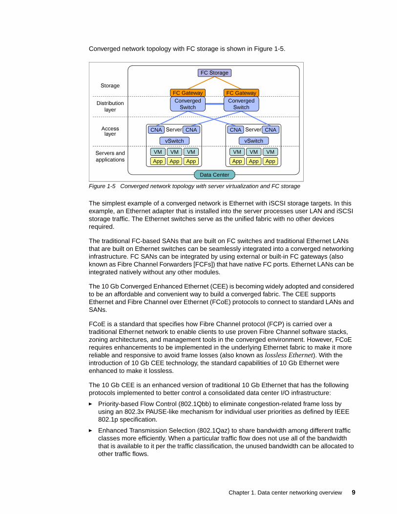
Converged network topology with FC storage is shown in Figure 1-5.
Figure 1-5 Converged network topology with server virtualization and FC storage
The simplest example of a converged network is Ethernet with iSCSI storage targets. In this example, an Ethernet adapter that is installed into the server processes user LAN and iSCSI storage traffic. The Ethernet switches serve as the unified fabric with no other devices required.
The traditional FC-based SANs that are built on FC switches and traditional Ethernet LANs that are built on Ethernet switches can be seamlessly integrated into a converged networking infrastructure. FC SANs can be integrated by using external or built-in FC gateways (also known as Fibre Channel Forwarders [FCFs]) that have native FC ports. Ethernet LANs can be integrated natively without any other modules.
The 10 Gb Converged Enhanced Ethernet (CEE) is becoming widely adopted and considered to be an affordable and convenient way to build a converged fabric. The CEE supports Ethernet and Fibre Channel over Ethernet (FCoE) protocols to connect to standard LANs and SANs.
FCoE is a standard that specifies how Fibre Channel protocol (FCP) is carried over a traditional Ethernet network to enable clients to use proven Fibre Channel software stacks, zoning architectures, and management tools in the converged environment. However, FCoE requires enhancements to be implemented in the underlying Ethernet fabric to make it more reliable and responsive to avoid frame losses (also known as lossless Ethernet). With the introduction of 10 Gb CEE technology, the standard capabilities of 10 Gb Ethernet were enhanced to make it lossless.
The 10 Gb CEE is an enhanced version of traditional 10 Gb Ethernet that has the following protocols implemented to better control a consolidated data center I/O infrastructure:
� Priority-based Flow Control (802.1Qbb) to eliminate congestion-related frame loss by using an 802.3x PAUSE-like mechanism for individual user priorities as defined by IEEE 802.1p specification.
� Enhanced Transmission Selection (802.1Qaz) to share bandwidth among different traffic classes more efficiently. When a particular traffic flow does not use all of the bandwidth that is available to it per the traffic classification, the unused bandwidth can be allocated to other traffic flows.
Data Center
Server
vSwitch
VM
App
VM
App
VM
App
Server
vSwitch
VM
App
VM
App
VM
App
Access layer
Distribution layer
Servers andapplications
StorageFC Gateway
ConvergedSwitch
ConvergedSwitch
CNA CNA CNA CNA
FC Gateway
FC Storage
Chapter 1. Data center networking overview 9
� Data Center Bridging (DCB) Exchange Protocol (part of 802.1Qaz coverage) to simplify network deployment and reduce configuration errors by providing autonegotiation of IEEE 802.1 DCB features between the NIC and the switch and between switches.
FCoE and CEE together form a solid foundation for data center infrastructure consolidation with converged networking by offering Fibre Channel Over Converged Enhanced Ethernet (FCoCEE) technology. The term FCoCEE does not represent any formal standard, and is used to enforce the meaning of CEE in an FCoE implementation. That is, FCoCEE means FCoE protocol that is running over CEE, and not over standard Ethernet. FCoCEE combines two formal standards (FCoE and CEE) into a single common term.
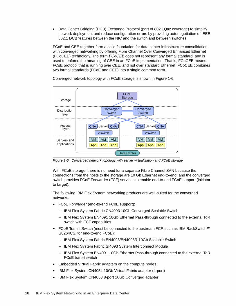
Converged network topology with FCoE storage is shown in Figure 1-6.
Figure 1-6 Converged network topology with server virtualization and FCoE storage
With FCoE storage, there is no need for a separate Fibre Channel SAN because the connections from the hosts to the storage are 10 Gb Ethernet end-to-end, and the converged switch provides FCoE Forwarder (FCF) services to enable end-to-end FCoE support (initiator to target).
The following IBM Flex System networking products are well-suited for the converged networks:
� FCoE Forwarder (end-to-end FCoE support):
– IBM Flex System Fabric CN4093 10Gb Converged Scalable Switch
– IBM Flex System EN4091 10Gb Ethernet Pass-through connected to the external ToR switch with FCF capabilities
� FCoE Transit Switch (must be connected to the upstream FCF, such as IBM RackSwitch™ G8264CS, for end-to-end FCoE):
– IBM Flex System Fabric EN4093/EN4093R 10Gb Scalable Switch
– IBM Flex System Fabric SI4093 System Interconnect Module
– IBM Flex System EN4091 10Gb Ethernet Pass-through connected to the external ToR FCoE transit switch
� Embedded Virtual Fabric adapters on the compute nodes
� IBM Flex System CN4054 10Gb Virtual Fabric adapter (4-port)
� IBM Flex System CN4058 8-port 10Gb Converged adapter
Data Center
Server
vSwitch
VM
App
VM
App
VM
App
Server
vSwitch
VM
App
VM
App
VM
App
Access layer
Distribution layer
Servers andapplications
Storage
ConvergedSwitch
ConvergedSwitch
CNA CNA CNA CNA
FCoEStorage
10 IBM Flex System Networking in an Enterprise Data Center
For more information about these products, see 2.2, “IBM Flex System Ethernet I/O modules” on page 19.
For more information about FCoE and FCoCEE, see An Introduction to Fibre Channel over Ethernet, and Fibre Channel over Convergence Enhanced Ethernet, REDP-4493.
1.3 Network virtualization
Network virtualization techniques can be used in the networking infrastructure to achieve the same benefits that are obtained through server and storage virtualization. Network virtualization can be seen as an umbrella term because many different techniques exist at many different levels of the networking infrastructure.
In the early ages of IT, communication lines were tightly coupled with systems and applications. The fact that one link can carry traffic for different applications and systems was one of the first manifestations of network virtualization, which was enabled by the standardization of interfaces, protocols, and drivers. In this case, one physical link is made up of different logical wires, so it is an example of one-to-many virtualization (or partitioning); that is, a single entity logically partitioned into multiple logical entities. The antithesis of one-to-many virtualization is many-to-one virtualization (aggregation); in this case, multiple entities are combined to represent one logical entity.
Current network virtualization techniques use partitioning and aggregation and include the following techniques:
� Network interface virtualization
These techniques refer to the Ethernet NICs and how they can be partitioned or aggregated and include NIC teaming and virtual NIC (vNIC) solutions.
� Network link virtualization
These techniques refer to how physical wires can be logically aggregated or partitioned to increase throughput and reliability or to provide traffic separation that uses the same physical infrastructure.
� Network node virtualization
These techniques refer to how network devices can be logically aggregated (for example, by stacking) or partitioned to provide logically isolated communications and traffic flows.
Going further, there are other technologies that although not being a specific component of the Enterprise Chassis Ethernet modules, are part of the overall virtualization efforts that are beginning to transform the data center infrastructure.
One such example is IBM Software Defined Network for Virtual Environments (SDN VE). SDN VE is a set of solutions that create a network overlay technology for virtualized servers. In much the way that Hypervisors created an overlay for server hardware that can then be shared seamlessly by the virtualized servers, a network overlay decouples the virtualized network from the physical underlying network. This permits the virtualized machines to make more intelligent usage of the physical networking infrastructure, without having to constantly reconfigure the physical components.
Chapter 1. Data center networking overview 11
SDN VE is a suite of products that are developed as part of the IBM Distributed Overlay Virtual Ethernet (DOVE) framework and includes the following components:
� The IBM 5000V is a distributed virtual switch (which is referred to as the dvs5000V), and replaces the vendor's vSwitch on the hypervisor. The dsv5000V provides integration with the upstream SDN VE infrastructure. It also provides more features such as ERSPAN, a remote port mirror for vSwitches.
� DOVE Connectivity Service (DCS): Manages policies and address distribution to the virtual switches that are part of the virtual network.
� DOVE Management Console (DMC): Provides a centralized point of control for configuring all components within the SDN VE network. The DMC has the management interface to manage networks and policies. This configuration and monitoring can be done through command-line interface (CLI), web interface, or REST API options.
� External Gateway: The SDN VE solution uses overlay encapsulation technology such as VXLAN or NVGRE to create virtual networks. To communicate between these virtual networks and the traditional network, SDN VE offers two external gateway options: the VLAN Gateway allows mapping of traditional Ethernet VLANs into virtual networks or the IP gateway allows external communication using the IPV4 protocol.
All of these components can be clustered to ensure high availability.
To learn more about SDN VE, see this website:
http://ibm.com/systems/networking/software/sdnve/index.html
IBM Flex System networking offerings can use all of these techniques to provide a flexible, scalable, highly available, manageable, and secure environment, as described in Chapter 3, “IBM Flex System data center network design basics” on page 55.
1.4 Conclusions
Consolidation began as a trend toward centralizing the scattered IT assets of an enterprise for better cost control, operational optimization, and efficiency. Virtualization introduced an abstraction layer between hardware and software, which allowed enterprises to consolidate even further and getting the most out of each physical server platform in the data center by running multiple virtual servers on it. This transformation has a direct effect on the networking infrastructure in a data center because the network must follow and support this changing environment.
We described several evolving architectural approaches to build a data center network that satisfies established availability, scalability, performance, security, and systems management requirements.
Based on these parameters, we can highlight some of the following important trends that affect the data center network design that must be considered during the network planning process:
� The virtual machine is the new IT building block inside the data center. The physical server platform is no longer the basic component but instead is made up of several logical resources that are aggregated in virtual resource pools.
� Network administrator responsibilities can no longer be limited by the NIC level; the server platforms’ network-specific features and requirements, such as vSwitches, also must be considered.
12 IBM Flex System Networking in an Enterprise Data Center

� The virtualization technologies that are available today (for servers, storage, and networks) decouple the logical function layer from the physical implementation layer so that physical connectivity becomes less meaningful than in the past. The network is becoming flattened, and an overlay or logical network that is placed on top of the physical infrastructure becomes critical in providing the connectivity between services and applications.
� The architecture view is moving from physical to logical and is focused on functions and how they can be deployed rather than on appliances and where they can be placed.
� The 10 Gb Ethernet networks reached their maturity and price attractiveness. They can provide sufficient bandwidth for virtual machines in virtualized server environments, and they are becoming a foundation of unified converged infrastructure.
� Although 10 Gb Ethernet is becoming a prevalent server network connectivity technology, there is a need to go beyond 10 Gb to avoid oversubscription in switch-to-switch connectivity, thus freeing up the room for emerging technologies, such as 40 Gb Ethernet.
� Network infrastructure must be VM-aware to ensure the end-to-end QoS and security policy enforcements.
� Pay as you grow scalability becomes an essential approach as increasing network bandwidth demands must be satisfied in a cost-efficient way with no disruption in providing network services.
� Infrastructure management integration becomes more important in this environment because the inter-relations between appliances and functions are more difficult to control and manage. Without integrated tools that simplify the data center operations, managing the infrastructure box-by-box becomes cumbersome and more difficult.
These approaches and technologies are incorporated into IBM Flex System.
Chapter 1. Data center networking overview 13

14 IBM Flex System Networking in an Enterprise Data Center
Chapter 2. IBM Flex System networking architecture and portfolio
IBM Flex System, a new category of computing and the next generation of Smarter Computing, offers intelligent workload deployment and management for maximum business agility. This chassis delivers high-speed performance complete with integrated servers, storage, and networking for multi-chassis management in data center compute environments. Furthermore, its flexible design can meet the needs of varying workloads with independently scalable IT resource pools for higher usage and lower cost per workload. Although increased security and resiliency protect vital information and promote maximum uptime, the integrated, easy-to-use management system reduces setup time and complexity, which provides a quicker path to return on investment (ROI).
This chapter includes the following topics:
� Enterprise Chassis I/O architecture� IBM Flex System Ethernet I/O modules� IBM Flex System Ethernet adapters
2
© Copyright IBM Corp. 2013. All rights reserved. 15
2.1 Enterprise Chassis I/O architecture
The Ethernet networking I/O architecture for the IBM Flex System Enterprise Chassis includes an array of connectivity options for server nodes that are installed in the enclosure. Users can decide to use a local switching model that provides superior performance, cable reduction and a rich feature set, or use pass-through technology and allow all Ethernet networking decisions to be made external to the Enterprise Chassis.
By far, the most versatile option is to use modules that provide local switching capabilities and advanced features that are fully integrated into the operation and management of the Enterprise Chassis. In particular, the EN4093 10Gb Scalable Switch module offers the maximum port density, highest throughput, and most advanced data center-class features to support the most demanding compute environments.
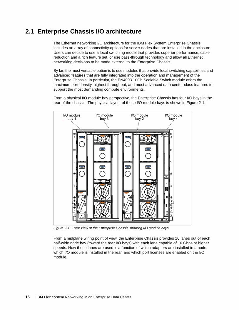
From a physical I/O module bay perspective, the Enterprise Chassis has four I/O bays in the rear of the chassis. The physical layout of these I/O module bays is shown in Figure 2-1.
Figure 2-1 Rear view of the Enterprise Chassis showing I/O module bays
From a midplane wiring point of view, the Enterprise Chassis provides 16 lanes out of each half-wide node bay (toward the rear I/O bays) with each lane capable of 16 Gbps or higher speeds. How these lanes are used is a function of which adapters are installed in a node, which I/O module is installed in the rear, and which port licenses are enabled on the I/O module.
I/O modulebay 1
I/O modulebay 3
I/O modulebay 2
I/O modulebay 4
16 IBM Flex System Networking in an Enterprise Data Center
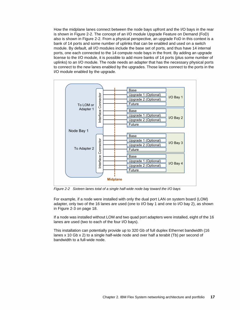
How the midplane lanes connect between the node bays upfront and the I/O bays in the rear is shown in Figure 2-2. The concept of an I/O module Upgrade Feature on Demand (FoD) also is shown in Figure 2-2. From a physical perspective, an upgrade FoD in this context is a bank of 14 ports and some number of uplinks that can be enabled and used on a switch module. By default, all I/O modules include the base set of ports, and thus have 14 internal ports, one each connected to the 14 compute node bays in the front. By adding an upgrade license to the I/O module, it is possible to add more banks of 14 ports (plus some number of uplinks) to an I/O module. The node needs an adapter that has the necessary physical ports to connect to the new lanes enabled by the upgrades. Those lanes connect to the ports in the I/O module enabled by the upgrade.
Figure 2-2 Sixteen lanes total of a single half-wide node bay toward the I/O bays
For example, if a node were installed with only the dual port LAN on system board (LOM) adapter, only two of the 16 lanes are used (one to I/O bay 1 and one to I/O bay 2), as shown in Figure 2-3 on page 18.
If a node was installed without LOM and two quad port adapters were installed, eight of the 16 lanes are used (two to each of the four I/O bays).
This installation can potentially provide up to 320 Gb of full duplex Ethernet bandwidth (16 lanes x 10 Gb x 2) to a single half-wide node and over half a terabit (Tb) per second of bandwidth to a full-wide node.
Node Bay 1
Inte
rface C
onnecto
r
To Adapter 2
To LOM or
Adapter 1
Inte
rface C
onnecto
r
Midplane
I/O Bay 1
Base
Upgrade 1 (Optional)
Upgrade 2 (Optional)
Future
I/O Bay 2
Base
Upgrade 1 (Optional)
Upgrade 2 (Optional)
Future
I/O Bay 3
Base
Upgrade 1 (Optional)
Upgrade 2 (Optional)
Future
I/O Bay 4
Base
Upgrade 1 (Optional)
Upgrade 2 (Optional)
Future
Chapter 2. IBM Flex System networking architecture and portfolio 17
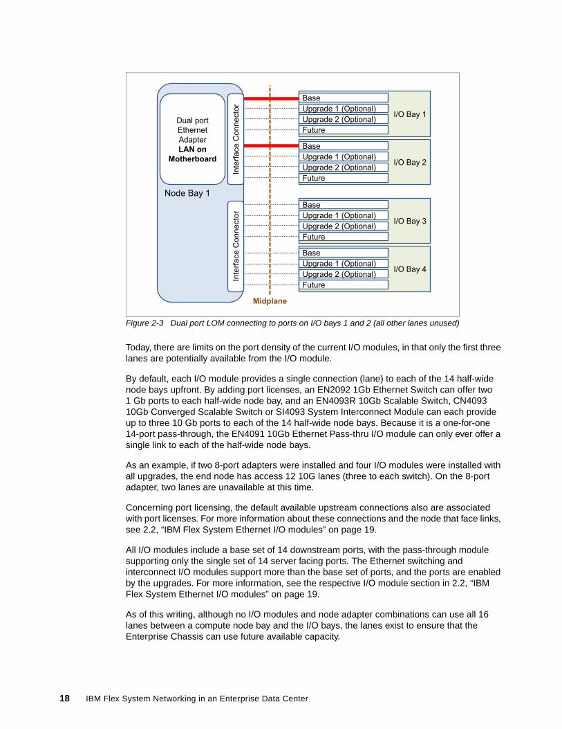
Figure 2-3 Dual port LOM connecting to ports on I/O bays 1 and 2 (all other lanes unused)
Today, there are limits on the port density of the current I/O modules, in that only the first three lanes are potentially available from the I/O module.
By default, each I/O module provides a single connection (lane) to each of the 14 half-wide node bays upfront. By adding port licenses, an EN2092 1Gb Ethernet Switch can offer two 1 Gb ports to each half-wide node bay, and an EN4093R 10Gb Scalable Switch, CN4093 10Gb Converged Scalable Switch or SI4093 System Interconnect Module can each provide up to three 10 Gb ports to each of the 14 half-wide node bays. Because it is a one-for-one 14-port pass-through, the EN4091 10Gb Ethernet Pass-thru I/O module can only ever offer a single link to each of the half-wide node bays.
As an example, if two 8-port adapters were installed and four I/O modules were installed with all upgrades, the end node has access 12 10G lanes (three to each switch). On the 8-port adapter, two lanes are unavailable at this time.
Concerning port licensing, the default available upstream connections also are associated with port licenses. For more information about these connections and the node that face links, see 2.2, “IBM Flex System Ethernet I/O modules” on page 19.
All I/O modules include a base set of 14 downstream ports, with the pass-through module supporting only the single set of 14 server facing ports. The Ethernet switching and interconnect I/O modules support more than the base set of ports, and the ports are enabled by the upgrades. For more information, see the respective I/O module section in 2.2, “IBM Flex System Ethernet I/O modules” on page 19.
As of this writing, although no I/O modules and node adapter combinations can use all 16 lanes between a compute node bay and the I/O bays, the lanes exist to ensure that the Enterprise Chassis can use future available capacity.
Node Bay 1
Inte
rface C
onnecto
rIn
terf
ace C
onnecto
r
Midplane
Dual port
Ethernet
Adapter
LAN on Motherboard
I/O Bay 1
Base
Upgrade 1 (Optional)
Upgrade 2 (Optional)
Future
I/O Bay 2
Base
Upgrade 1 (Optional)
Upgrade 2 (Optional)
Future
I/O Bay 3
Base
Upgrade 1 (Optional)
Upgrade 2 (Optional)
Future
I/O Bay 4
Base
Upgrade 1 (Optional)
Upgrade 2 (Optional)
Future
18 IBM Flex System Networking in an Enterprise Data Center
Beyond the physical aspects of the hardware, there are certain logical aspects that ensure that the Enterprise Chassis can integrate seamlessly into any modern data centers infrastructure.
Many of these enhancements, such as vNIC, VMready, and 802.1Qbg, revolve around integrating virtualized servers into the environment. Fibre Channel over Ethernet (FCoE) allows users to converge their Fibre Channel traffic onto their 10 Gb Ethernet network, which reduces the number of cables and points of management that is necessary to connect the Enterprise Chassis to the upstream infrastructures.
The wide range of physical and logical Ethernet networking options that are available today and in development ensure that the Enterprise Chassis can meet the most demanding I/O connectivity challenges now and as the data center evolves.
2.2 IBM Flex System Ethernet I/O modules
The IBM Flex System Enterprise Chassis features a number of Ethernet I/O module solutions that provide a combination of 1 Gb and 10 Gb ports to the servers and 1 Gb, 10 Gb, and 40 Gb for uplink connectivity to the outside upstream infrastructure. The IBM Flex System Enterprise Chassis ensures that a suitable selection is available to meet the needs of the server nodes.
The following Ethernet I/O modules are available for deployment with the Enterprise Chassis:
� IBM Flex System EN2092 1Gb Ethernet Scalable Switch� IBM Flex System EN4091 10Gb Ethernet Pass-thru� IBM Flex System Fabric EN4093 and EN4093R 10Gb Scalable Switches� IBM Flex System Fabric CN4093 10Gb Converged Scalable Switch� IBM Flex System Fabric SI4093 System Interconnect Module� IBM Flex System EN6131 40Gb Ethernet Switch� I/O modules and cables
These modules are described next.
2.2.1 IBM Flex System EN2092 1Gb Ethernet Scalable Switch
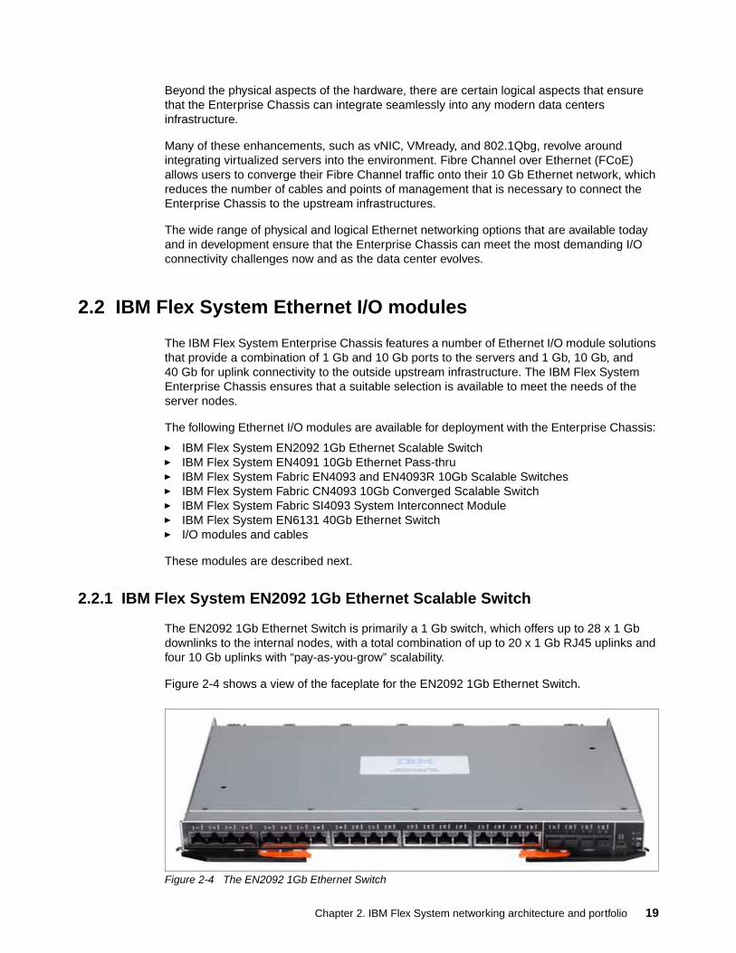
The EN2092 1Gb Ethernet Switch is primarily a 1 Gb switch, which offers up to 28 x 1 Gb downlinks to the internal nodes, with a total combination of up to 20 x 1 Gb RJ45 uplinks and four 10 Gb uplinks with “pay-as-you-grow” scalability.
Figure 2-4 shows a view of the faceplate for the EN2092 1Gb Ethernet Switch.
Figure 2-4 The EN2092 1Gb Ethernet Switch
Chapter 2. IBM Flex System networking architecture and portfolio 19
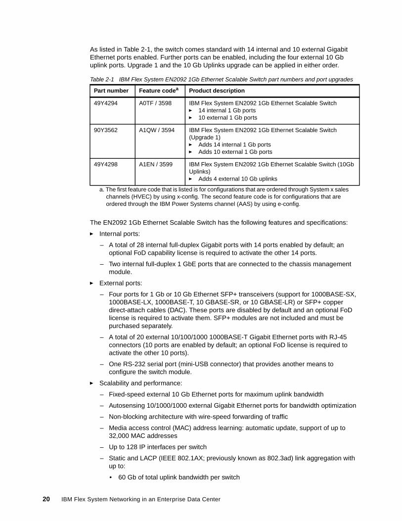
As listed in Table 2-1, the switch comes standard with 14 internal and 10 external Gigabit Ethernet ports enabled. Further ports can be enabled, including the four external 10 Gb uplink ports. Upgrade 1 and the 10 Gb Uplinks upgrade can be applied in either order.
Table 2-1 IBM Flex System EN2092 1Gb Ethernet Scalable Switch part numbers and port upgrades
The EN2092 1Gb Ethernet Scalable Switch has the following features and specifications:
� Internal ports:
– A total of 28 internal full-duplex Gigabit ports with 14 ports enabled by default; an optional FoD capability license is required to activate the other 14 ports.
– Two internal full-duplex 1 GbE ports that are connected to the chassis management module.
� External ports:
– Four ports for 1 Gb or 10 Gb Ethernet SFP+ transceivers (support for 1000BASE-SX, 1000BASE-LX, 1000BASE-T, 10 GBASE-SR, or 10 GBASE-LR) or SFP+ copper direct-attach cables (DAC). These ports are disabled by default and an optional FoD license is required to activate them. SFP+ modules are not included and must be purchased separately.
– A total of 20 external 10/100/1000 1000BASE-T Gigabit Ethernet ports with RJ-45 connectors (10 ports are enabled by default; an optional FoD license is required to activate the other 10 ports).
– One RS-232 serial port (mini-USB connector) that provides another means to configure the switch module.
� Scalability and performance:
– Fixed-speed external 10 Gb Ethernet ports for maximum uplink bandwidth
– Autosensing 10/1000/1000 external Gigabit Ethernet ports for bandwidth optimization
– Non-blocking architecture with wire-speed forwarding of traffic
– Media access control (MAC) address learning: automatic update, support of up to 32,000 MAC addresses
– Up to 128 IP interfaces per switch
– Static and LACP (IEEE 802.1AX; previously known as 802.3ad) link aggregation with up to:
• 60 Gb of total uplink bandwidth per switch
Part number Feature codea
a. The first feature code that is listed is for configurations that are ordered through System x sales channels (HVEC) by using x-config. The second feature code is for configurations that are ordered through the IBM Power Systems channel (AAS) by using e-config.
Product description
49Y4294 A0TF / 3598 IBM Flex System EN2092 1Gb Ethernet Scalable Switch� 14 internal 1 Gb ports� 10 external 1 Gb ports
90Y3562 A1QW / 3594 IBM Flex System EN2092 1Gb Ethernet Scalable Switch (Upgrade 1)� Adds 14 internal 1 Gb ports� Adds 10 external 1 Gb ports
49Y4298 A1EN / 3599 IBM Flex System EN2092 1Gb Ethernet Scalable Switch (10Gb Uplinks)� Adds 4 external 10 Gb uplinks
20 IBM Flex System Networking in an Enterprise Data Center
• 64 trunk groups• 16 ports per group
– Support for jumbo frames (up to 9,216 bytes)
– Broadcast/multicast storm control
– IGMP snooping for limit flooding of IP multicast traffic
– IGMP filtering to control multicast traffic for hosts that participate in multicast groups
– Configurable traffic distribution schemes over aggregated links
– Fast port forwarding and fast uplink convergence for rapid STP convergence
� Availability and redundancy:
– Virtual Router Redundancy Protocol (VRRP) for Layer 3 router redundancy
– IEEE 802.1D Spanning-tree to providing L2 redundancy, including support for the following components:
• Multiple STP (MSTP) for topology optimization, up to 32 STP instances are supported by single switch (previously known as 802.1s)
• Rapid STP (RSTP) provides rapid STP convergence for critical delay-sensitive traffic, such as voice or video (previously known as 802.1w)
– Per-VLAN Rapid STP (PVRST) to seamlessly integrate into Cisco infrastructures
– Layer 2 Trunk Failover to support active and standby configurations of network adapter teaming on compute nodes
– Hot Links provides basic link redundancy with fast recovery for network topologies that require Spanning Tree to be turned off
� VLAN support:
– Up to 4095 active VLANs supported per switch, with VLAN numbers that range from 1 to 4094 (4095 is used for internal management functions only)
– 802.1Q VLAN tagging support on all ports
– Private VLANs
� Security:
– VLAN-based, MAC-based, and IP-based ACLs– 802.1x port-based authentication– Multiple user IDs and passwords– User access control– Radius, TACACS+, and LDAP authentication and authorization
� Quality of service (QoS):
– Support for IEEE 802.1p, IP ToS/DSCP, and ACL-based (MAC/IP source and destination addresses, VLANs) traffic classification and processing
– Traffic shaping and re-marking based on defined policies
– Eight Weighted Round Robin (WRR) priority queues per port for processing qualified traffic
� IP v4 Layer 3 functions:
– Host management
– IP forwarding
– IP filtering with ACLs, up to 896 ACLs supported
– VRRP for router redundancy
Chapter 2. IBM Flex System networking architecture and portfolio 21
– Support for up to 128 static routes
– Routing protocol support (RIP v1, RIP v2, OSPF v2, and BGP-4), up to 2048 entries in a routing table
– Support for DHCP Relay
– Support for IGMP snooping and IGMP relay
– Support for Protocol Independent Multicast (PIM) in Sparse Mode (PIM-SM) and Dense Mode (PIM-DM).
� IP v6 Layer 3 functions:
– IPv6 host management (except default switch management IP address)– IPv6 forwarding– Up to 128 static routes– Support for OSPF v3 routing protocol– IPv6 filtering with ACLs
� Virtualization: VMready
� Manageability:
– Simple Network Management Protocol (SNMP V1, V2, and V3)– HTTP browser GUI– Telnet interface for command-line interface (CLI)– Secure Shell (SSH)– Serial interface for CLI– Scriptable CLI– Firmware image update (TFTP and FTP)– Network Time Protocol (NTP) for switch clock synchronization
� Monitoring:
– Switch LEDs for external port status and switch module status indication
– Remote Monitoring (RMON) agent to collect statistics and proactively monitor switch performance
– Port mirroring for analyzing network traffic that passes through the switch
– Change tracking and remote logging with the syslog feature
– Support for the sFLOW agent for monitoring traffic in data networks (separate sFLOW analyzer required elsewhere)
– Power-on self-test (POST) diagnostic tests
For more information, see IBM Flex System EN2092 1Gb Ethernet Scalable Switch, TIPS0861, which is available at this website:
http://www.redbooks.ibm.com/abstracts/tips0861.html?Open
22 IBM Flex System Networking in an Enterprise Data Center
2.2.2 IBM Flex System EN4091 10Gb Ethernet Pass-thru
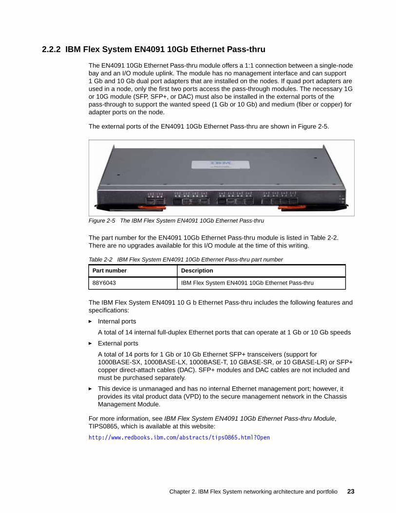
The EN4091 10Gb Ethernet Pass-thru module offers a 1:1 connection between a single-node bay and an I/O module uplink. The module has no management interface and can support 1 Gb and 10 Gb dual port adapters that are installed on the nodes. If quad port adapters are used in a node, only the first two ports access the pass-through modules. The necessary 1G or 10G module (SFP, SFP+, or DAC) must also be installed in the external ports of the pass-through to support the wanted speed (1 Gb or 10 Gb) and medium (fiber or copper) for adapter ports on the node.
The external ports of the EN4091 10Gb Ethernet Pass-thru are shown in Figure 2-5.
Figure 2-5 The IBM Flex System EN4091 10Gb Ethernet Pass-thru
The part number for the EN4091 10Gb Ethernet Pass-thru module is listed in Table 2-2. There are no upgrades available for this I/O module at the time of this writing.
Table 2-2 IBM Flex System EN4091 10Gb Ethernet Pass-thru part number
The IBM Flex System EN4091 10 G b Ethernet Pass-thru includes the following features and specifications:
� Internal ports
A total of 14 internal full-duplex Ethernet ports that can operate at 1 Gb or 10 Gb speeds
� External ports
A total of 14 ports for 1 Gb or 10 Gb Ethernet SFP+ transceivers (support for 1000BASE-SX, 1000BASE-LX, 1000BASE-T, 10 GBASE-SR, or 10 GBASE-LR) or SFP+ copper direct-attach cables (DAC). SFP+ modules and DAC cables are not included and must be purchased separately.
� This device is unmanaged and has no internal Ethernet management port; however, it provides its vital product data (VPD) to the secure management network in the Chassis Management Module.
For more information, see IBM Flex System EN4091 10Gb Ethernet Pass-thru Module, TIPS0865, which is available at this website:
http://www.redbooks.ibm.com/abstracts/tips0865.html?Open
Part number Description
88Y6043 IBM Flex System EN4091 10Gb Ethernet Pass-thru
Chapter 2. IBM Flex System networking architecture and portfolio 23
2.2.3 IBM Flex System Fabric EN4093 and EN4093R 10Gb Scalable Switches
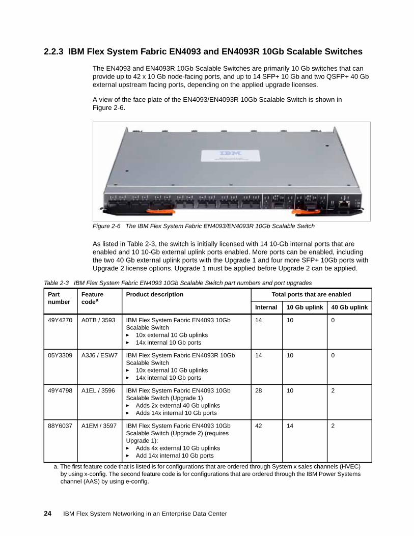
The EN4093 and EN4093R 10Gb Scalable Switches are primarily 10 Gb switches that can provide up to 42 x 10 Gb node-facing ports, and up to 14 SFP+ 10 Gb and two QSFP+ 40 Gb external upstream facing ports, depending on the applied upgrade licenses.
A view of the face plate of the EN4093/EN4093R 10Gb Scalable Switch is shown in Figure 2-6.
Figure 2-6 The IBM Flex System Fabric EN4093/EN4093R 10Gb Scalable Switch
As listed in Table 2-3, the switch is initially licensed with 14 10-Gb internal ports that are enabled and 10 10-Gb external uplink ports enabled. More ports can be enabled, including the two 40 Gb external uplink ports with the Upgrade 1 and four more SFP+ 10Gb ports with Upgrade 2 license options. Upgrade 1 must be applied before Upgrade 2 can be applied.
Table 2-3 IBM Flex System Fabric EN4093 10Gb Scalable Switch part numbers and port upgrades
Partnumber
Featurecodea
a. The first feature code that is listed is for configurations that are ordered through System x sales channels (HVEC) by using x-config. The second feature code is for configurations that are ordered through the IBM Power Systems channel (AAS) by using e-config.
Product description Total ports that are enabled
Internal 10 Gb uplink 40 Gb uplink
49Y4270 A0TB / 3593 IBM Flex System Fabric EN4093 10Gb Scalable Switch� 10x external 10 Gb uplinks� 14x internal 10 Gb ports
14 10 0
05Y3309 A3J6 / ESW7 IBM Flex System Fabric EN4093R 10Gb Scalable Switch� 10x external 10 Gb uplinks� 14x internal 10 Gb ports
14 10 0
49Y4798 A1EL / 3596 IBM Flex System Fabric EN4093 10Gb Scalable Switch (Upgrade 1)� Adds 2x external 40 Gb uplinks� Adds 14x internal 10 Gb ports
28 10 2
88Y6037 A1EM / 3597 IBM Flex System Fabric EN4093 10Gb Scalable Switch (Upgrade 2) (requires Upgrade 1):� Adds 4x external 10 Gb uplinks � Add 14x internal 10 Gb ports
42 14 2
24 IBM Flex System Networking in an Enterprise Data Center

The IBM Flex System Fabric EN4093 and EN4093R 10Gb Scalable Switches have the following features and specifications:
� Internal ports:
– A total of 42 internal full-duplex 10 Gigabit ports (14 ports are enabled by default; optional FoD licenses are required to activate the remaining 28 ports).
– Two internal full-duplex 1 GbE ports that are connected to the chassis management module.
� External ports:
– A total of 14 ports for 1 Gb or 10 Gb Ethernet SFP+ transceivers (support for 1000BASE-SX, 1000BASE-LX, 1000BASE-T, 10 GBASE-SR, or 10 GBASE-LR) or SFP+ copper direct-attach cables (DAC). There are 10 ports enabled by default and an optional FoD license is required to activate the remaining four ports. SFP+ modules and DAC cables are not included and must be purchased separately.
– Two ports for 40 Gb Ethernet QSFP+ transceivers or QSFP+ DACs (these ports are disabled by default; an optional FoD license is required to activate them). QSFP+ modules and DAC cables are not included and must be purchased separately.
– One RS-232 serial port (mini-USB connector) that provides another means to configure the switch module.
� Scalability and performance:
– 40 Gb Ethernet ports for extreme uplink bandwidth and performance
– Fixed-speed external 10 Gb Ethernet ports to use 10 Gb core infrastructure
– Support for 1G speeds on uplinks via proper SFP selection
– Non-blocking architecture with wire-speed forwarding of traffic and aggregated throughput of 1.28 Tbps
– Media access control (MAC) address learning:
• Automatic update• Support of up to 128,000 MAC addresses
– Up to 128 IP interfaces per switch
– Static and LACP (IEEE 802.1AX; previously known as 802.3ad) link aggregation with up to:
• 220 Gb of total uplink bandwidth per switch• 64 trunk groups• 16 ports per group
– Support for cross switch aggregations via vLAG
– Support for jumbo frames (up to 9,216 bytes)
– Broadcast/multicast storm control
– IGMP snooping to limit flooding of IP multicast traffic
– IGMP filtering to control multicast traffic for hosts that participate in multicast groups
– Configurable traffic distribution schemes over aggregated links
– Fast port forwarding and fast uplink convergence for rapid STP convergence
� Availability and redundancy:
– VRRP for Layer 3 router redundancy
– IEEE 802.1D Spanning-tree to providing L2 redundancy, including support for:
Chapter 2. IBM Flex System networking architecture and portfolio 25
• Multiple STP (MSTP) for topology optimization, up to 32 STP instances are supported by single switch (previously known as 802.1s)
• Rapid STP (RSTP) provides rapid STP convergence for critical delay-sensitive traffic, such as voice or video (previously known as 802.1w)
• Per-VLAN Rapid STP (PVRST) to seamlessly integrate into Cisco infrastructures
– Layer 2 Trunk Failover to support active and standby configurations of network adapter that team on compute nodes
– Hot Links provides basic link redundancy with fast recovery for network topologies that require Spanning Tree to be turned off
� VLAN support:
– Up to 4095 active VLANs supported per switch, with VLAN numbers that range from 1 to 4094 (4095 is used for internal management functions only)
– 802.1Q VLAN tagging support on all ports
– Private VLANs
� Security:
– VLAN-based, MAC-based, and IP-based ACLs– 802.1x port-based authentication– Multiple user IDs and passwords– User access control– Radius, TACACS+, and LDAP authentication and authorization
� QoS:
– Support for IEEE 802.1p, IP ToS/DSCP, and ACL-based (MAC/IP source and destination addresses, VLANs) traffic classification and processing
– Traffic shaping and re-marking based on defined policies
– Eight WRR priority queues per port for processing qualified traffic
� IP v4 Layer 3 functions:
– Host management
– IP forwarding
– IP filtering with ACLs, up to 896 ACLs supported
– VRRP for router redundancy
– Support for up to 128 static routes
– Routing protocol support (RIP v1, RIP v2, OSPF v2, and BGP-4), up to 2048 entries in a routing table
– Support for DHCP Relay
– Support for IGMP snooping and IGMP relay
– Support for Protocol Independent Multicast (PIM) in Sparse Mode (PIM-SM) and Dense Mode (PIM-DM).
� IP v6 Layer 3 functions:
– IPv6 host management (except default switch management IP address)– IPv6 forwarding– Up to 128 static routes– Support of OSPF v3 routing protocol– IPv6 filtering with ACLs
26 IBM Flex System Networking in an Enterprise Data Center
� Virtualization:
– Virtual NICs (vNICs): Ethernet, iSCSI, or FCoE traffic is supported on vNICs
– Unified fabric ports (UFPs): Ethernet or FCoE traffic is supported on UFPs
– Virtual link aggregation groups (vLAGs)
– 802.1Qbg Edge Virtual Bridging (EVB) is an emerging IEEE standard for allowing networks to become virtual machine (VM)-aware.
Virtual Ethernet Bridging (VEB) and Virtual Ethernet Port Aggregator (VEPA) are mechanisms for switching between VMs on the same hypervisor.
Edge Control Protocol (ECP) is a transport protocol that operates between two peers over an IEEE 802 LAN providing reliable, in-order delivery of upper layer protocol data units.
Virtual Station Interface (VSI) Discovery and Configuration Protocol (VDP) allows centralized configuration of network policies that will persist with the VM, independent of its location.
EVB Type-Length-Value (TLV) is used to discover and configure VEPA, ECP, and VDP.
– VMready
– Switch partitioning (SPAR)
� Converged Enhanced Ethernet:
– Priority-Based Flow Control (PFC) (IEEE 802.1Qbb) extends 802.3x standard flow control to allow the switch to pause traffic that is based on the 802.1p priority value in the VLAN tag of each packet.
– Enhanced Transmission Selection (ETS) (IEEE 802.1Qaz) provides a method for allocating link bandwidth that is based on the 802.1p priority value in the VLAN tag of each packet.
– Data Center Bridging Capability Exchange Protocol (DCBX) (IEEE 802.1AB) allows neighboring network devices to exchange information about their capabilities.
� FCoE:
– FC-BB5 FCoE specification compliant– FCoE transit switch operations– FCoE Initialization Protocol (FIP) support for automatic ACL configuration– FCoE Link Aggregation Group (LAG) support– Multi-hop RDMA over Converged Ethernet (RoCE) with LAG support
� Stacking:
– Up to eight switches in a stack
– Hybrid stacking support (from two to six EN4093/EN4093R switches with two CN4093 switches)
– FCoE support (EN4093R only)
– vNIC support
– 802.1Qbg support
� Manageability:
– Simple Network Management Protocol (SNMP V1, V2, and V3)– HTTP browser GUI– Telnet interface for CLI– SSH– Serial interface for CLI
Chapter 2. IBM Flex System networking architecture and portfolio 27
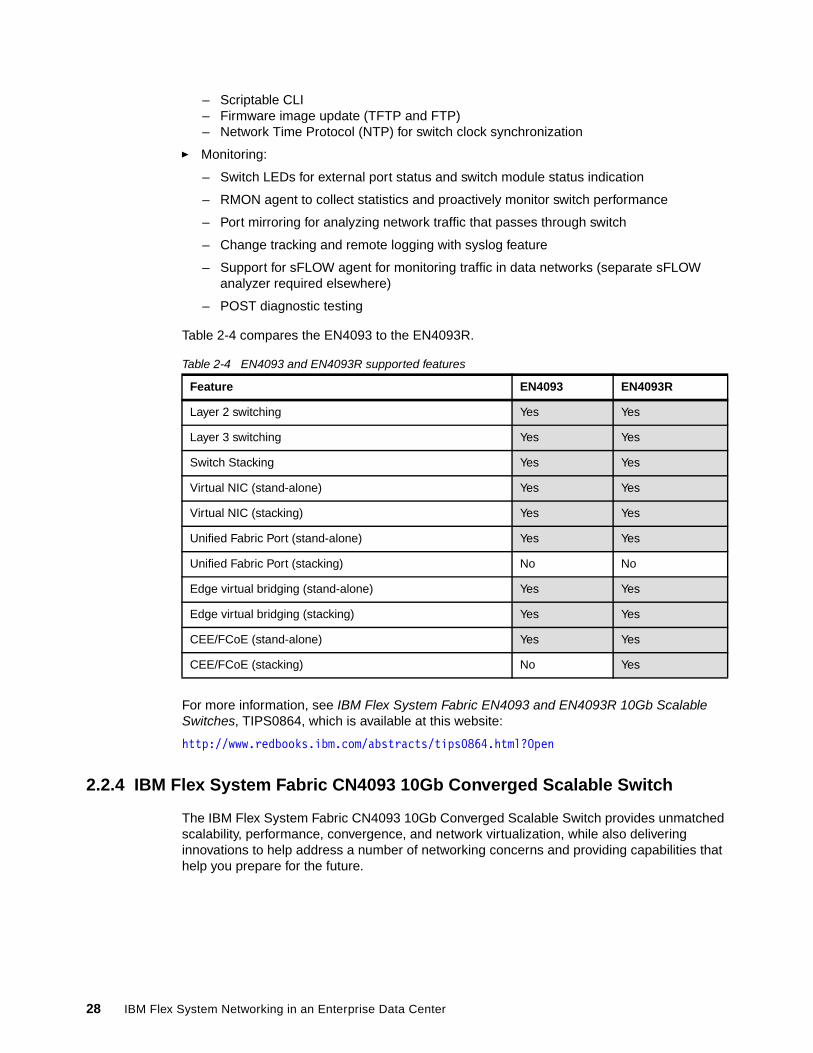
– Scriptable CLI– Firmware image update (TFTP and FTP)– Network Time Protocol (NTP) for switch clock synchronization
� Monitoring:
– Switch LEDs for external port status and switch module status indication
– RMON agent to collect statistics and proactively monitor switch performance
– Port mirroring for analyzing network traffic that passes through switch
– Change tracking and remote logging with syslog feature
– Support for sFLOW agent for monitoring traffic in data networks (separate sFLOW analyzer required elsewhere)
– POST diagnostic testing
Table 2-4 compares the EN4093 to the EN4093R.
Table 2-4 EN4093 and EN4093R supported features
For more information, see IBM Flex System Fabric EN4093 and EN4093R 10Gb Scalable Switches, TIPS0864, which is available at this website:
http://www.redbooks.ibm.com/abstracts/tips0864.html?Open
2.2.4 IBM Flex System Fabric CN4093 10Gb Converged Scalable Switch
The IBM Flex System Fabric CN4093 10Gb Converged Scalable Switch provides unmatched scalability, performance, convergence, and network virtualization, while also delivering innovations to help address a number of networking concerns and providing capabilities that help you prepare for the future.
Feature EN4093 EN4093R
Layer 2 switching Yes Yes
Layer 3 switching Yes Yes
Switch Stacking Yes Yes
Virtual NIC (stand-alone) Yes Yes
Virtual NIC (stacking) Yes Yes
Unified Fabric Port (stand-alone) Yes Yes
Unified Fabric Port (stacking) No No
Edge virtual bridging (stand-alone) Yes Yes
Edge virtual bridging (stacking) Yes Yes
CEE/FCoE (stand-alone) Yes Yes
CEE/FCoE (stacking) No Yes
28 IBM Flex System Networking in an Enterprise Data Center
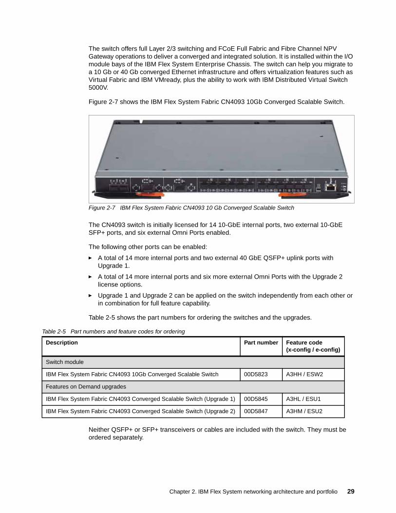
The switch offers full Layer 2/3 switching and FCoE Full Fabric and Fibre Channel NPV Gateway operations to deliver a converged and integrated solution. It is installed within the I/O module bays of the IBM Flex System Enterprise Chassis. The switch can help you migrate to a 10 Gb or 40 Gb converged Ethernet infrastructure and offers virtualization features such as Virtual Fabric and IBM VMready, plus the ability to work with IBM Distributed Virtual Switch 5000V.
Figure 2-7 shows the IBM Flex System Fabric CN4093 10Gb Converged Scalable Switch.
Figure 2-7 IBM Flex System Fabric CN4093 10 Gb Converged Scalable Switch
The CN4093 switch is initially licensed for 14 10-GbE internal ports, two external 10-GbE SFP+ ports, and six external Omni Ports enabled.
The following other ports can be enabled:
� A total of 14 more internal ports and two external 40 GbE QSFP+ uplink ports with Upgrade 1.
� A total of 14 more internal ports and six more external Omni Ports with the Upgrade 2 license options.
� Upgrade 1 and Upgrade 2 can be applied on the switch independently from each other or in combination for full feature capability.
Table 2-5 shows the part numbers for ordering the switches and the upgrades.
Table 2-5 Part numbers and feature codes for ordering
Neither QSFP+ or SFP+ transceivers or cables are included with the switch. They must be ordered separately.
Description Part number Feature code(x-config / e-config)
Switch module
IBM Flex System Fabric CN4093 10Gb Converged Scalable Switch 00D5823 A3HH / ESW2
Features on Demand upgrades
IBM Flex System Fabric CN4093 Converged Scalable Switch (Upgrade 1) 00D5845 A3HL / ESU1
IBM Flex System Fabric CN4093 Converged Scalable Switch (Upgrade 2) 00D5847 A3HM / ESU2
Chapter 2. IBM Flex System networking architecture and portfolio 29

The switch does not include a serial management cable. However, IBM Flex System Management Serial Access Cable, 90Y9338, is supported and contains two cables, a mini-USB-to-RJ45 serial cable and a mini-USB-to-DB9 serial cable, either of which can be used to connect to the switch locally for configuration tasks and firmware updates.
The following base switch and upgrades are available:
� 00D5823 is the part number for the physical device, which comes with 14 internal 10 GbE ports enabled (one to each node bay), two external 10 GbE SFP+ ports that are enabled to connect to a top-of-rack switch or other devices identified as EXT1 and EXT2, and six Omni Ports enabled to connect to Ethernet or Fibre Channel networking infrastructure, depending on the SFP+ cable or transceiver that is used. The six Omni ports are from the 12 that are labeled on the switch as EXT11 through EXT22.
� 00D5845 (Upgrade 1) can be applied on the base switch when you need more uplink bandwidth with two 40 GbE QSFP+ ports that can be converted into 4x 10 GbE SFP+ DAC links with the optional break-out cables. These are labeled EXT3, EXT7 or EXT3-EXT6, EXT7-EXT10 if converted. This upgrade also enables 14 more internal ports, for a total of 28 ports, to provide more bandwidth to the compute nodes using 4-port expansion cards.
� 00D5847 (Upgrade 2) can be applied on the base switch when you need more external Omni Ports on the switch or if you want more internal bandwidth to the node bays. The upgrade enables the remaining six external Omni Ports from range EXT11 through EXT22, plus 14 more internal 10 Gb ports, for a total of 28 internal ports, to provide more bandwidth to the compute nodes by using 4-port expansion cards.
� Both 00D5845 (Upgrade 1) and 00D5847 (Upgrade 2) can be applied on the switch at the same time so that you can use six ports on an 8-port expansion card, and use all the external ports on the switch.
Table 2-6 shows the switch upgrades and the ports they enable.
Table 2-6 CN4093 10 Gb Converged Scalable Switch part numbers and port upgrades
The IBM Flex System Fabric CN4093 10Gb Converged Scalable Switch has the following features and specifications:
� Internal ports:
– A total of 42 internal full-duplex 10 Gigabit ports. (A total of 14 ports are enabled by default. Optional FoD licenses are required to activate the remaining 28 ports.)
– Two internal full-duplex 1 GbE ports that are connected to the Chassis Management Module.
Partnumber
Featurecodea
a. The first feature code that is listed is for configurations that are ordered through System x sales channels (HVEC) by using x-config. The second feature code is for configurations that are ordered through the IBM Power Systems channel (AAS) by using e-config.
Description Total ports that are enabled
Internal10Gb
External10Gb SFP+
External10Gb Omni
External40Gb QSFP+
00D5823 A3HH / ESW2 Base switch (no upgrades) 14 2 6 0
00D5845 A3HL / ESU1 Add Upgrade 1 28 2 6 2
00D5847 A3HM / ESU2 Add Upgrade 2 28 2 12 0
00D584500D5847
A3HL / ESU1A3HM / ESU2
Add both Upgrade 1 and Upgrade 2
42 2 12 2
30 IBM Flex System Networking in an Enterprise Data Center
� External ports:
– Two ports for 1 Gb or 10 Gb Ethernet SFP+ transceivers (support for 1000BASE-SX, 1000BASE-LX, 1000BASE-T, 10GBASE-SR, 10GBASE-LR, or SFP+ copper direct-attach cables (DACs)). These two ports are enabled by default. SFP+ modules and DACs are not included and must be purchased separately.
– Twelve IBM Omni Ports. Each of them can operate as 10 Gb Ethernet (support for 10GBASE-SR, 10GBASE-LR, or 10 GbE SFP+ DACs), or auto-negotiating as 4/8 Gb Fibre Channel, depending on the SFP+ transceiver that is installed in the port. The first six ports are enabled by default. An optional FoD license is required to activate the remaining six ports. SFP+ modules and DACs are not included and must be purchased separately.
– Two ports for 40 Gb Ethernet QSFP+ transceivers or QSFP+ DACs. (Ports are disabled by default. An optional FoD license is required to activate them.) Also, you can use break-out cables to break out each 40 GbE port into four 10 GbE SFP+ connections. QSFP+ modules and DACs are not included and must be purchased separately.
– One RS-232 serial port (mini-USB connector) that provides another means to configure the switch module.
� Scalability and performance:
– 40 Gb Ethernet ports for extreme uplink bandwidth and performance.
– Fixed-speed external 10 Gb Ethernet ports to use the 10 Gb core infrastructure.
– Non-blocking architecture with wire-speed forwarding of traffic and aggregated throughput of 1.28 Tbps on Ethernet ports.
– MAC address learning: Automatic update, and support for up to 128,000 MAC addresses.
– Up to 128 IP interfaces per switch.
– Static and LACP (IEEE 802.3ad) link aggregation, up to 220 Gb of total uplink bandwidth per switch, up to 64 trunk groups, and up to 16 ports per group.
– Support for jumbo frames (up to 9,216 bytes).
– Broadcast/multicast storm control.
– IGMP snooping to limit flooding of IP multicast traffic.
– IGMP filtering to control multicast traffic for hosts that participate in multicast groups.
– Configurable traffic distribution schemes over trunk links that are based on source/destination IP or MAC addresses or both.
– Fast port forwarding and fast uplink convergence for rapid STP convergence.
� Availability and redundancy:
– VRRP for Layer 3 router redundancy.
– IEEE 802.1D STP for providing L2 redundancy.
– IEEE 802.1s MSTP for topology optimization. Up to 32 STP instances are supported by a single switch.
– IEEE 802.1w RSTP provides rapid STP convergence for critical delay-sensitive traffic, such as voice or video.
– PVRST enhancements.
Omni Ports support: Note: Omni Ports do not support 1 Gb Ethernet operations.
Chapter 2. IBM Flex System networking architecture and portfolio 31
– Layer 2 Trunk Failover to support active/standby configurations of network adapter teaming on compute nodes.
– Hot Links provides basic link redundancy with fast recovery for network topologies that require Spanning Tree to be turned off.
� VLAN support:
– Up to 1024 VLANs supported per switch, with VLAN numbers from 1 - 4095. (4095 is used for management module’s connection only).
– 802.1Q VLAN tagging support on all ports.
– Private VLANs.
� Security:
– VLAN-based, MAC-based, and IP-based access control lists (ACLs).– 802.1x port-based authentication.– Multiple user IDs and passwords.– User access control.– Radius, TACACS+, and LDAP authentication and authorization.
� QoS
– Support for IEEE 802.1p, IP ToS/DSCP, and ACL-based (MAC/IP source and destination addresses, VLANs) traffic classification and processing.
– Traffic shaping and re-marking based on defined policies.
– Eight WRR priority queues per port for processing qualified traffic.
� IP v4 Layer 3 functions:
– Host management.
– IP forwarding.
– IP filtering with ACLs, with up to 896 ACLs supported.
– VRRP for router redundancy.
– Support for up to 128 static routes.
– Routing protocol support (RIP v1, RIP v2, OSPF v2, and BGP-4), for up to 2048 entries in a routing table.
– Support for DHCP Relay.
– Support for IGMP snooping and IGMP relay.
– Support for PIM in PIM-SM and PIM-DM.
� IP v6 Layer 3 functions:
– IPv6 host management (except for a default switch management IP address).– IPv6 forwarding.– Up to 128 static routes.– Support for OSPF v3 routing protocol.– IPv6 filtering with ACLs.
� Virtualization:
– vNICs: Ethernet, iSCSI, or FCoE traffic is supported on vNICs.
– UFPs: Ethernet or FCoE traffic is supported on UFPs
– 802.1Qbg Edge Virtual Bridging (EVB) is an emerging IEEE standard for allowing networks to become virtual machine (VM)-aware:
• Virtual Ethernet Bridging (VEB) and Virtual Ethernet Port Aggregator (VEPA) are mechanisms for switching between VMs on the same hypervisor.
32 IBM Flex System Networking in an Enterprise Data Center
• Edge Control Protocol (ECP) is a transport protocol that operates between two peers over an IEEE 802 LAN providing reliable and in-order delivery of upper layer protocol data units.
• Virtual Station Interface (VSI) Discovery and Configuration Protocol (VDP) allows centralized configuration of network policies that persists with the VM, independent of its location.
• EVB Type-Length-Value (TLV) is used to discover and configure VEPA, ECP, and VDP.
– VMready.
� Converged Enhanced Ethernet
– Priority-Based Flow Control (PFC) (IEEE 802.1Qbb) extends 802.3x standard flow control to allow the switch to pause traffic that is based on the 802.1p priority value in each packet’s VLAN tag.
– Enhanced Transmission Selection (ETS) (IEEE 802.1Qaz) provides a method for allocating link bandwidth that is based on the 802.1p priority value in each packet’s VLAN tag.
– Data center Bridging Capability Exchange Protocol (DCBX) (IEEE 802.1AB) allows neighboring network devices to exchange information about their capabilities.
� Fibre Channel over Ethernet (FCoE)
– FC-BB5 FCoE specification compliant.
– Native FC Forwarder switch operations.
– End-to-end FCoE support (initiator to target).
– FCoE Initialization Protocol (FIP) support.
� Fibre Channel
– Omni Ports support 4/8 Gb FC when FC SFPs+ are installed in these ports.
– Full Fabric mode for end-to-end FCoE or NPV Gateway mode for external FC SAN attachments (support for IBM B-type, Brocade, and Cisco MDS external SANs).
– Fabric services in Full Fabric mode:
• Name Server• Registered State Change Notification (RSCN)• Login services• Zoning
� Stacking
– Hybrid stacking support (from two to six EN4093/EN4093R switches with two CN4093 switches)
– FCoE support
– vNIC support
– 802.1Qbg support
� Manageability
– Simple Network Management Protocol (SNMP V1, V2, and V3).
– HTTP browser GUI.
– Telnet interface for CLI.
– SSH.
– Secure FTP (sFTP).
Chapter 2. IBM Flex System networking architecture and portfolio 33
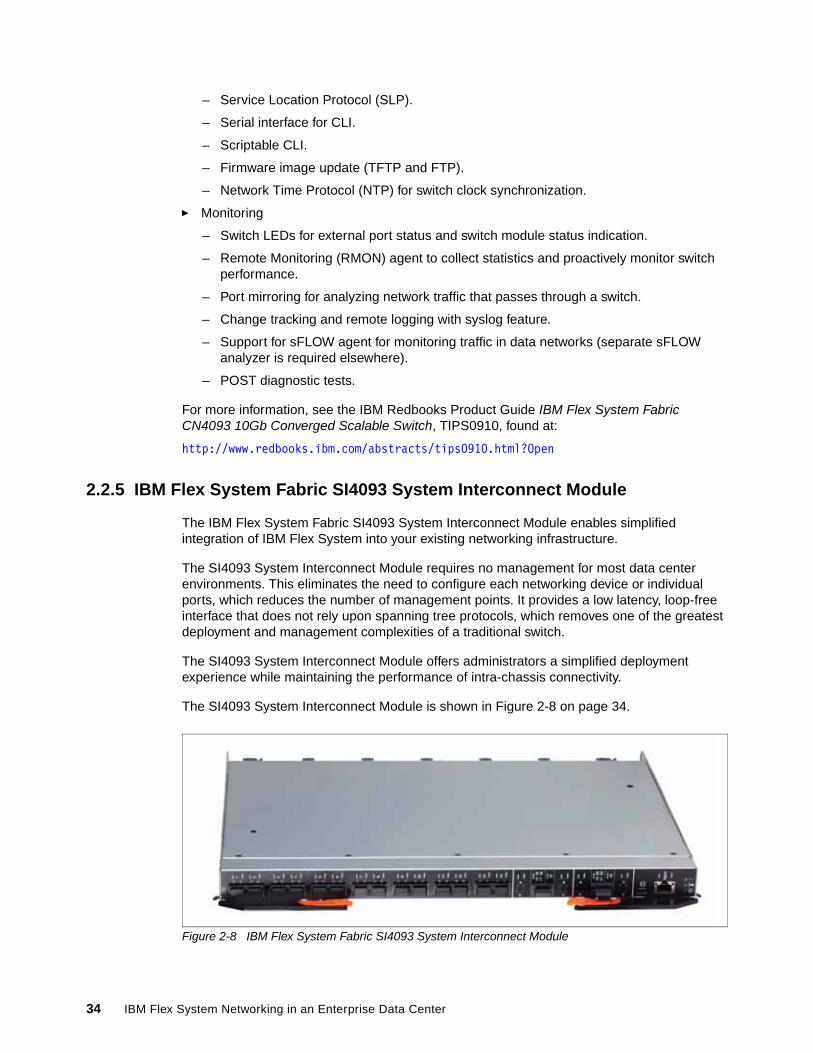
– Service Location Protocol (SLP).
– Serial interface for CLI.
– Scriptable CLI.
– Firmware image update (TFTP and FTP).
– Network Time Protocol (NTP) for switch clock synchronization.
� Monitoring
– Switch LEDs for external port status and switch module status indication.
– Remote Monitoring (RMON) agent to collect statistics and proactively monitor switch performance.
– Port mirroring for analyzing network traffic that passes through a switch.
– Change tracking and remote logging with syslog feature.
– Support for sFLOW agent for monitoring traffic in data networks (separate sFLOW analyzer is required elsewhere).
– POST diagnostic tests.
For more information, see the IBM Redbooks Product Guide IBM Flex System Fabric CN4093 10Gb Converged Scalable Switch, TIPS0910, found at:
http://www.redbooks.ibm.com/abstracts/tips0910.html?Open
2.2.5 IBM Flex System Fabric SI4093 System Interconnect Module
The IBM Flex System Fabric SI4093 System Interconnect Module enables simplified integration of IBM Flex System into your existing networking infrastructure.
The SI4093 System Interconnect Module requires no management for most data center environments. This eliminates the need to configure each networking device or individual ports, which reduces the number of management points. It provides a low latency, loop-free interface that does not rely upon spanning tree protocols, which removes one of the greatest deployment and management complexities of a traditional switch.
The SI4093 System Interconnect Module offers administrators a simplified deployment experience while maintaining the performance of intra-chassis connectivity.
The SI4093 System Interconnect Module is shown in Figure 2-8 on page 34.
Figure 2-8 IBM Flex System Fabric SI4093 System Interconnect Module
34 IBM Flex System Networking in an Enterprise Data Center
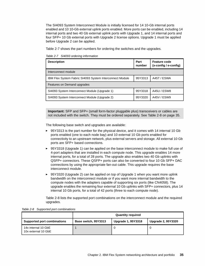
The SI4093 System Interconnect Module is initially licensed for 14 10-Gb internal ports enabled and 10 10-Gb external uplink ports enabled. More ports can be enabled, including 14 internal ports and two 40 Gb external uplink ports with Upgrade 1, and 14 internal ports and four SFP+ 10 Gb external ports with Upgrade 2 license options. Upgrade 1 must be applied before Upgrade 2 can be applied.
Table 2-7 shows the part numbers for ordering the switches and the upgrades.
Table 2-7 SI4093 ordering information
The following base switch and upgrades are available:
� 95Y3313 is the part number for the physical device, and it comes with 14 internal 10 Gb ports enabled (one to each node bay) and 10 external 10 Gb ports enabled for connectivity to an upstream network, plus external servers and storage. All external 10 Gb ports are SFP+ based connections.
� 95Y3318 (Upgrade 1) can be applied on the base interconnect module to make full use of 4-port adapters that are installed in each compute node. This upgrade enables 14 more internal ports, for a total of 28 ports. The upgrade also enables two 40 Gb uplinks with QSFP+ connectors. These QSFP+ ports can also be converted to four 10 Gb SFP+ DAC connections by using the appropriate fan-out cable. This upgrade requires the base interconnect module.
� 95Y3320 (Upgrade 2) can be applied on top of Upgrade 1 when you want more uplink bandwidth on the interconnect module or if you want more internal bandwidth to the compute nodes with the adapters capable of supporting six ports (like CN4058). The upgrade enables the remaining four external 10 Gb uplinks with SFP+ connectors, plus 14 internal 10 Gb ports, for a total of 42 ports (three to each compute node).
Table 2-8 lists the supported port combinations on the interconnect module and the required upgrades.
Table 2-8 Supported port combinations
Description Partnumber
Feature code(x-config / e-config)
Interconnect module
IBM Flex System Fabric SI4093 System Interconnect Module 95Y3313 A45T / ESWA
Features on Demand upgrades
SI4093 System Interconnect Module (Upgrade 1) 95Y3318 A45U / ESW8
SI4093 System Interconnect Module (Upgrade 2) 95Y3320 A45V / ESW9
Important: SFP and SFP+ (small form-factor pluggable plus) transceivers or cables are not included with the switch. They must be ordered separately. See Table 2-8 on page 35.
Quantity required
Supported port combinations Base switch, 95Y3313 Upgrade 1, 95Y3318 Upgrade 2, 95Y3320
14x internal 10 GbE10x external 10 GbE
1 0 0
Chapter 2. IBM Flex System networking architecture and portfolio 35
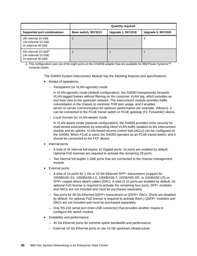
The SI4093 System Interconnect Module has the following features and specifications:
� Modes of operations:
– Transparent (or VLAN-agnostic) mode
In VLAN-agnostic mode (default configuration), the SI4093 transparently forwards VLAN tagged frames without filtering on the customer VLAN tag, which provides an end host view to the upstream network. The interconnect module provides traffic consolidation in the chassis to minimize TOR port usage, and it enables server-to-server communication for optimum performance (for example, vMotion). It can be connected to the FCoE transit switch or FCoE gateway (FC Forwarder) device.
– Local Domain (or VLAN-aware) mode
In VLAN-aware mode (optional configuration), the SI4093 provides more security for multi-tenant environments by extending client VLAN traffic isolation to the interconnect module and its uplinks. VLAN-based access control lists (ACLs) can be configured on the SI4093. When FCoE is used, the SI4093 operates as an FCoE transit switch, and it should be connected to the FCF device.
� Internal ports:
– A total of 42 internal full-duplex 10 Gigabit ports; 14 ports are enabled by default. Optional FoD licenses are required to activate the remaining 28 ports.
– Two internal full-duplex 1 GbE ports that are connected to the chassis management module.
� External ports:
– A total of 14 ports for 1 Gb or 10 Gb Ethernet SFP+ transceivers (support for 1000BASE-SX, 1000BASE-LX, 1000BASE-T, 10GBASE-SR, or 10GBASE-LR) or SFP+ copper direct-attach cables (DAC). A total of 10 ports are enabled by default. An optional FoD license is required to activate the remaining four ports. SFP+ modules and DACs are not included and must be purchased separately.
– Two ports for 40 Gb Ethernet QSFP+ transceivers or QSFP+ DACs. (Ports are disabled by default. An optional FoD license is required to activate them.) QSFP+ modules and DACs are not included and must be purchased separately.
– One RS-232 serial port (mini-USB connector) that provides another means to configure the switch module.
� Scalability and performance:
– 40 Gb Ethernet ports for extreme uplink bandwidth and performance.
– External 10 Gb Ethernet ports to use 10 Gb upstream infrastructure.
28x internal 10 GbE10x external 10 GbE2x external 40 GbE
1 1 0
42x internal 10 GbEa
14x external 10 GbE2x external 40 GbE
1 1 1
a. This configuration uses six of the eight ports on the CN4058 adapter that are available for IBM Power Systems™ compute nodes.
Quantity required
Supported port combinations Base switch, 95Y3313 Upgrade 1, 95Y3318 Upgrade 2, 95Y3320
36 IBM Flex System Networking in an Enterprise Data Center
– Non-blocking architecture with wire-speed forwarding of traffic and aggregated throughput of 1.28 Tbps.
– Media access control (MAC) address learning: automatic update, support for up to 128,000 MAC addresses.
– Static and LACP (IEEE 802.3ad) link aggregation, up to 220 Gb of total uplink bandwidth per interconnect module.
– Support for jumbo frames (up to 9,216 bytes).
� Availability and redundancy:
– Layer 2 Trunk Failover to support active and standby configurations of network adapter teaming on compute nodes.
– Built in link redundancy with loop prevention without a need for Spanning Tree protocol.
� VLAN support:
– Up to 32 VLANs supported per interconnect module SPAR partition, with VLAN numbers 1 - 4095. (4095 is used for management module’s connection only.)
– 802.1Q VLAN tagging support on all ports.
� Security:
– VLAN-based access control lists (ACLs) (VLAN-aware mode).– Multiple user IDs and passwords.– User access control.– Radius, TACACS+, and LDAP authentication and authorization.
� QoS
Support for IEEE 802.1p traffic classification and processing.
� Virtualization:
– Switch Independent Virtual NIC (vNIC2): Ethernet, iSCSI, or FCoE traffic is supported on vNICs.
– SPAR:
• SPAR forms separate virtual switching contexts by segmenting the data plane of the switch. Data plane traffic is not shared between SPARs on the same switch.
• SPAR operates as a Layer 2 broadcast network. Hosts on the same VLAN attached to a SPAR can communicate with each other and with the upstream switch. Hosts on the same VLAN but attached to different SPARs communicate through the upstream switch.
• SPAR is implemented as a dedicated VLAN with a set of internal server ports and a single uplink port or link aggregation (LAG). Multiple uplink ports or LAGs are not allowed in SPAR. A port can be a member of only one SPAR.
� Converged Enhanced Ethernet:
– Priority-Based Flow Control (PFC) (IEEE 802.1Qbb) extends 802.3x standard flow control to allow the switch to pause traffic based on the 802.1p priority value in each packet’s VLAN tag.
– Enhanced Transmission Selection (ETS) (IEEE 802.1Qaz) provides a method for allocating link bandwidth based on the 802.1p priority value in each packet’s VLAN tag.
– Data Center Bridging Capability Exchange Protocol (DCBX) (IEEE 802.1AB) allows neighboring network devices to exchange information about their capabilities.
Chapter 2. IBM Flex System networking architecture and portfolio 37
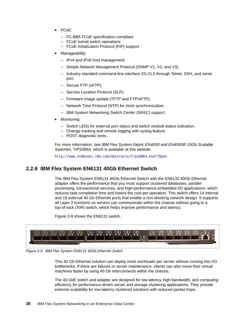
� FCoE:
– FC-BB5 FCoE specification compliant– FCoE transit switch operations– FCoE Initialization Protocol (FIP) support
� Manageability:
– IPv4 and IPv6 host management.
– Simple Network Management Protocol (SNMP V1, V2, and V3).
– Industry standard command-line interface (IS-CLI) through Telnet, SSH, and serial port.
– Secure FTP (sFTP).
– Service Location Protocol (SLP).
– Firmware image update (TFTP and FTP/sFTP).
– Network Time Protocol (NTP) for clock synchronization.
– IBM System Networking Switch Center (SNSC) support.
� Monitoring:
– Switch LEDs for external port status and switch module status indication.– Change tracking and remote logging with syslog feature.– POST diagnostic tests.
For more information, see IBM Flex System Fabric EN4093 and EN4093R 10Gb Scalable Switches, TIPS0864, which is available at this website:
http://www.redbooks.ibm.com/abstracts/tips0864.html?Open
2.2.6 IBM Flex System EN6131 40Gb Ethernet Switch
The IBM Flex System EN6131 40Gb Ethernet Switch with the EN6132 40Gb Ethernet adapter offers the performance that you must support clustered databases, parallel processing, transactional services, and high-performance embedded I/O applications, which reduces task completion time and lowers the cost per operation. This switch offers 14 internal and 18 external 40 Gb Ethernet ports that enable a non-blocking network design. It supports all Layer 2 functions so servers can communicate within the chassis without going to a top-of-rack (ToR) switch, which helps improve performance and latency.
Figure 2-9 shows the EN6131 switch.
Figure 2-9 IBM Flex System EN6131 40Gb Ethernet Switch
This 40 Gb Ethernet solution can deploy more workloads per server without running into I/O bottlenecks. If there are failures or server maintenance, clients can also move their virtual machines faster by using 40 Gb interconnects within the chassis.
The 40 GbE switch and adapter are designed for low latency, high bandwidth, and computing efficiency for performance-driven server and storage clustering applications. They provide extreme scalability for low-latency clustered solutions with reduced packet hops.
38 IBM Flex System Networking in an Enterprise Data Center
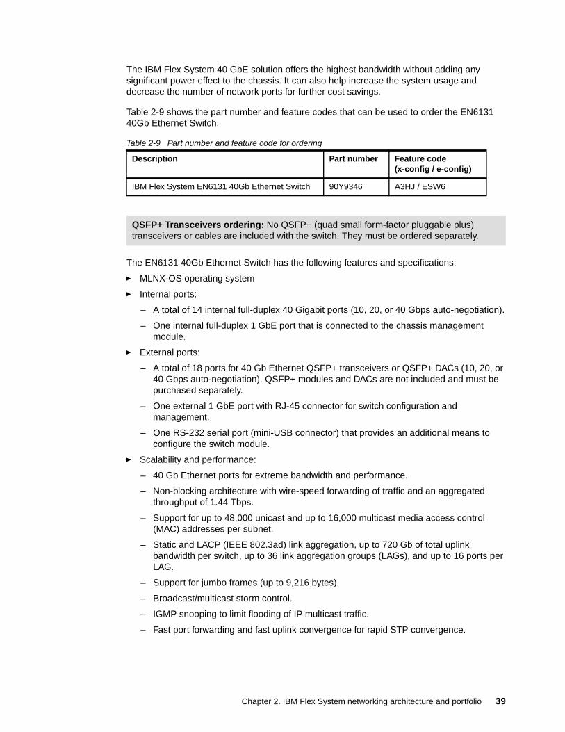
The IBM Flex System 40 GbE solution offers the highest bandwidth without adding any significant power effect to the chassis. It can also help increase the system usage and decrease the number of network ports for further cost savings.
Table 2-9 shows the part number and feature codes that can be used to order the EN6131 40Gb Ethernet Switch.
Table 2-9 Part number and feature code for ordering
The EN6131 40Gb Ethernet Switch has the following features and specifications:
� MLNX-OS operating system
� Internal ports:
– A total of 14 internal full-duplex 40 Gigabit ports (10, 20, or 40 Gbps auto-negotiation).
– One internal full-duplex 1 GbE port that is connected to the chassis management module.
� External ports:
– A total of 18 ports for 40 Gb Ethernet QSFP+ transceivers or QSFP+ DACs (10, 20, or 40 Gbps auto-negotiation). QSFP+ modules and DACs are not included and must be purchased separately.
– One external 1 GbE port with RJ-45 connector for switch configuration and management.
– One RS-232 serial port (mini-USB connector) that provides an additional means to configure the switch module.
� Scalability and performance:
– 40 Gb Ethernet ports for extreme bandwidth and performance.
– Non-blocking architecture with wire-speed forwarding of traffic and an aggregated throughput of 1.44 Tbps.
– Support for up to 48,000 unicast and up to 16,000 multicast media access control (MAC) addresses per subnet.
– Static and LACP (IEEE 802.3ad) link aggregation, up to 720 Gb of total uplink bandwidth per switch, up to 36 link aggregation groups (LAGs), and up to 16 ports per LAG.
– Support for jumbo frames (up to 9,216 bytes).
– Broadcast/multicast storm control.
– IGMP snooping to limit flooding of IP multicast traffic.
– Fast port forwarding and fast uplink convergence for rapid STP convergence.
Description Part number Feature code(x-config / e-config)
IBM Flex System EN6131 40Gb Ethernet Switch 90Y9346 A3HJ / ESW6
QSFP+ Transceivers ordering: No QSFP+ (quad small form-factor pluggable plus) transceivers or cables are included with the switch. They must be ordered separately.
Chapter 2. IBM Flex System networking architecture and portfolio 39
� Availability and redundancy:
– IEEE 802.1D STP for providing L2 redundancy.
– IEEE 802.1w Rapid STP (RSTP) provides rapid STP convergence for critical delay-sensitive traffic such as voice or video.
� VLAN support:
– Up to 4094 VLANs are supported per switch, with VLAN numbers 1 - 4094.– 802.1Q VLAN tagging support on all ports.
� Security:
– Up to 24,000 rules with VLAN-based, MAC-based, protocol-based, and IP-based access control lists (ACLs).
– User access control: Multiple user IDs and passwords
– RADIUS, TACACS+, and LDAP authentication and authorization
� QoS:
– Support for IEEE 802.1p traffic processing.
– Traffic shaping that is based on defined policies.
– Four WRR priority queues per port for processing qualified traffic.
– PFC (IEEE 802.1Qbb) extends 802.3x standard flow control to allow the switch to pause traffic based on the 802.1p priority value in each packet’s VLAN tag.
– ETS (IEEE 802.1Qaz) provides a method for allocating link bandwidth based on the 802.1p priority value in each packet’s VLAN tag.
� Manageability:
– IPv4 and IPv6 host management.– Simple Network Management Protocol (SNMP V1, V2, and V3).– WebUI graphical user interface.– IS-CLI through Telnet, SSH, and serial port.– LLDP to advertise the device's identity, capabilities, and neighbors.– TFTP, FTP, and SCP.– NTP for clock synchronization.
� Monitoring:
– Switch LEDs for external port status and switch module status indication.
– Port mirroring for analyzing network traffic passing through the switch.
– Change tracking and remote logging with the syslog feature.
– Support for sFLOW agent for monitoring traffic in data networks (separate sFLOW collector/analyzer is required elsewhere).
– POST diagnostic tests.
For more information and example configurations, see IBM Flex System EN6131 40Gb Ethernet Switch, TIPS0911, which is available at this website:
http://www.redbooks.ibm.com/abstracts/tips0911.html?Open
40 IBM Flex System Networking in an Enterprise Data Center

2.2.7 I/O modules and cables
The Ethernet I/O modules support for interface modules and cables is shown in Table 2-10.
Table 2-10 Modules and cables supported in Ethernet I/O modules
All Ethernet /O modules are restricted to the use of the SFP/SFP+ modules that are listed in Table 2-10.
Part number Description EN2092 EN4091
EN4093EN4093R CN4093 SI4093 EN6131
44W4408 10GbE 850 nm Fiber SFP+ Transceiver (SR)
Yes Yes Yes Yes Yes No
46C3447 IBM SFP+ SR Transceiver Yes Yes Yes Yes Yes No
90Y9412 IBM SFP+ LR Transceiver Yes Yes Yes Yes Yes No
81Y1622 IBM SFP SX Transceiver Yes Yes Yes Yes Yes No
81Y1618 IBM SFP RJ45 Transceiver Yes Yes Yes Yes Yes No
90Y9424 IBM SFP LX Transceiver Yes Yes Yes Yes Yes No
49Y7884 IBM QSFP+ SR Transceiver No No Yes Yes Yes Yes
90Y9427 1m IBM Passive DAC SFP+ Cable Yes No Yes Yes Yes No
90Y9430 3m IBM Passive DAC SFP+ Cable Yes No Yes Yes Yes No
90Y9433 5m IBM Passive DAC SFP+ Cable Yes No Yes Yes Yes No
49Y7886 1m IBM QSFP+ DAC Break Out Cbl. No No Yes Yes Yes No
49Y7887 3m IBM QSFP+ DAC Break Out Cbl. No No Yes Yes Yes No
49Y7888 5m IBM QSFP+ DAC Break Out Cbl. No No Yes Yes Yes No
90Y3519 10m IBM QSFP+ MTP Optical cable No No Yes Yes Yes Yes
90Y3521 30m IBM QSFP+ MTP Optical cable No No Yes Yes Yes Yes
49Y7890 1m IBM QSFP+-to-QSFP+ cable No No Yes Yes Yes No
49Y7891 3m IBM QSFP+-to-QSFP+ cable No No Yes Yes Yes Yes
00D5810 5m IBM QSFP+ to QSFP+ Cable No No No No No Yes
00D5813 7m IBM QSFP+ to QSFP+ Cable No No No No No Yes
95Y0323 1m IBM Active DAC SFP+ Cable No Yes No No No No
95Y0326 3m IBM Active DAC SFP+ Cable No Yes No No No No
95Y0329 5m IBM Active DAC SFP+ Cable No Yes No No No No
81Y8295 1m 10GE Twinax Act Copper SFP+ No Yes No No No No
81Y8296 3m 10GE Twinax Act Copper SFP+ No Yes No No No No
81Y8297 5m 10GE Twinax Act Copper SFP+ No Yes No No No No
Chapter 2. IBM Flex System networking architecture and portfolio 41
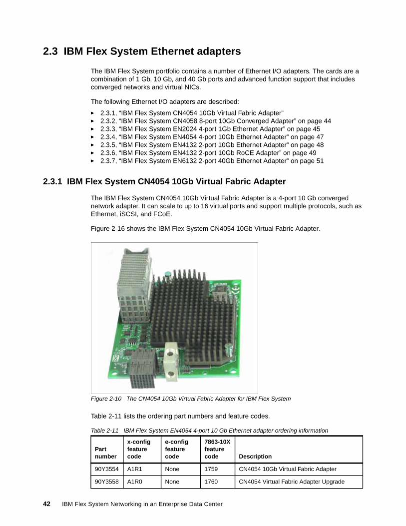
2.3 IBM Flex System Ethernet adapters
The IBM Flex System portfolio contains a number of Ethernet I/O adapters. The cards are a combination of 1 Gb, 10 Gb, and 40 Gb ports and advanced function support that includes converged networks and virtual NICs.
The following Ethernet I/O adapters are described:
� 2.3.1, “IBM Flex System CN4054 10Gb Virtual Fabric Adapter”� 2.3.2, “IBM Flex System CN4058 8-port 10Gb Converged Adapter” on page 44� 2.3.3, “IBM Flex System EN2024 4-port 1Gb Ethernet Adapter” on page 45� 2.3.4, “IBM Flex System EN4054 4-port 10Gb Ethernet Adapter” on page 47� 2.3.5, “IBM Flex System EN4132 2-port 10Gb Ethernet Adapter” on page 48� 2.3.6, “IBM Flex System EN4132 2-port 10Gb RoCE Adapter” on page 49� 2.3.7, “IBM Flex System EN6132 2-port 40Gb Ethernet Adapter” on page 51
2.3.1 IBM Flex System CN4054 10Gb Virtual Fabric Adapter
The IBM Flex System CN4054 10Gb Virtual Fabric Adapter is a 4-port 10 Gb converged network adapter. It can scale to up to 16 virtual ports and support multiple protocols, such as Ethernet, iSCSI, and FCoE.
Figure 2-16 shows the IBM Flex System CN4054 10Gb Virtual Fabric Adapter.
Figure 2-10 The CN4054 10Gb Virtual Fabric Adapter for IBM Flex System
Table 2-11 lists the ordering part numbers and feature codes.
Table 2-11 IBM Flex System EN4054 4-port 10 Gb Ethernet adapter ordering information
Partnumber
x-config feature code
e-config feature code
7863-10Xfeature code Description
90Y3554 A1R1 None 1759 CN4054 10Gb Virtual Fabric Adapter
90Y3558 A1R0 None 1760 CN4054 Virtual Fabric Adapter Upgrade
42 IBM Flex System Networking in an Enterprise Data Center
The IBM Flex System CN4054 10Gb Virtual Fabric Adapter has the following features and specifications:
� Dual ASIC Emulex BladeEngine 3 (BE3) controller.
� Operates as a 4-port 1/10 Gb Ethernet adapter, or supports up to 16 Virtual Network Interface Cards (vNICs).
� In virtual NIC (vNIC) mode, it supports:
– Virtual port bandwidth allocation in 100 Mbps increments.
– Up to 16 virtual ports per adapter (four per port).
– With the CN4054 Virtual Fabric Adapter Upgrade, 90Y3558, four of the 16 vNICs (one per port) support iSCSI or FCoE.
� Support for two vNIC modes: IBM Virtual Fabric Mode and Switch Independent Mode.
� Wake On LAN support.
� With the CN4054 Virtual Fabric Adapter Upgrade, 90Y3558, the adapter adds FCoE and iSCSI hardware initiator support. iSCSI support is implemented as a full offload and presents an iSCSI adapter to the operating system.
� TCP offload Engine (TOE) support with Windows Server 2003, 2008, and 2008 R2 (TCP Chimney) and Linux.
� The connection and its state are passed to the TCP offload engine.
� Data transmit and receive is handled by the adapter.
� Supported by iSCSI.
� Connection to either 1 Gb or 10 Gb data center infrastructure (1 Gb and 10 Gb auto-negotiation).
� PCI Express 3.0 x8 host interface.
� Full-duplex capability.
� Bus-mastering support.
� DMA support.
� PXE support.
� IPv4/IPv6 TCP, UDP checksum offload:
– Large send offload– Large receive offload – RSS – IPv4 TCP Chimney offload – TCP Segmentation offload
� VLAN insertion and extraction.
� Jumbo frames up to 9000 bytes.
� Load balancing and failover support, including AFT, SFT, ALB, teaming support, and IEEE 802.3ad.
� Enhanced Ethernet (draft):
– Enhanced Transmission Selection (ETS) (P802.1Qaz).
– Priority-based Flow Control (PFC) (P802.1Qbb).
– Data Center Bridging Capabilities eXchange Protocol, CIN-DCBX, and CEE-DCBX (P802.1Qaz).
� Supports Serial over LAN (SoL).
Chapter 2. IBM Flex System networking architecture and portfolio 43
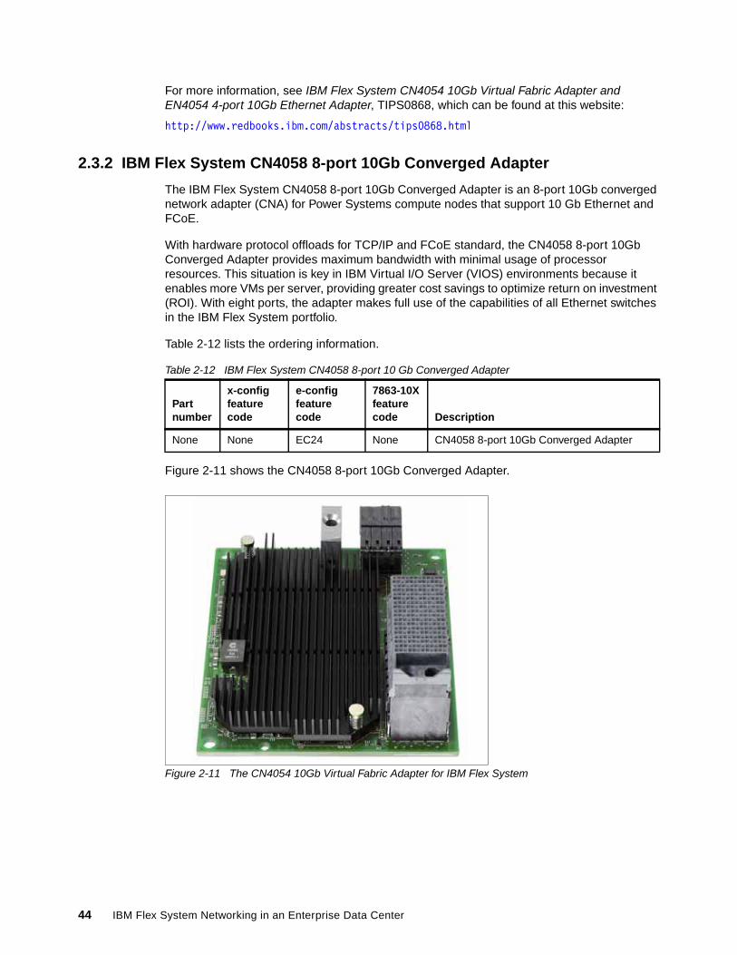
For more information, see IBM Flex System CN4054 10Gb Virtual Fabric Adapter and EN4054 4-port 10Gb Ethernet Adapter, TIPS0868, which can be found at this website:
http://www.redbooks.ibm.com/abstracts/tips0868.html
2.3.2 IBM Flex System CN4058 8-port 10Gb Converged Adapter
The IBM Flex System CN4058 8-port 10Gb Converged Adapter is an 8-port 10Gb converged network adapter (CNA) for Power Systems compute nodes that support 10 Gb Ethernet and FCoE.
With hardware protocol offloads for TCP/IP and FCoE standard, the CN4058 8-port 10Gb Converged Adapter provides maximum bandwidth with minimal usage of processor resources. This situation is key in IBM Virtual I/O Server (VIOS) environments because it enables more VMs per server, providing greater cost savings to optimize return on investment (ROI). With eight ports, the adapter makes full use of the capabilities of all Ethernet switches in the IBM Flex System portfolio.
Table 2-12 lists the ordering information.
Table 2-12 IBM Flex System CN4058 8-port 10 Gb Converged Adapter
Figure 2-11 shows the CN4058 8-port 10Gb Converged Adapter.
Figure 2-11 The CN4054 10Gb Virtual Fabric Adapter for IBM Flex System
Partnumber
x-config feature code
e-configfeature code
7863-10Xfeature code Description
None None EC24 None CN4058 8-port 10Gb Converged Adapter
44 IBM Flex System Networking in an Enterprise Data Center
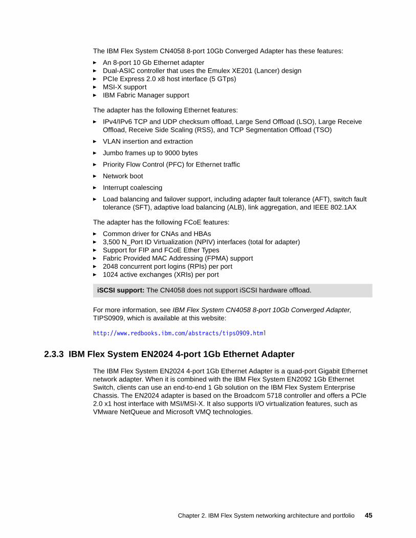
The IBM Flex System CN4058 8-port 10Gb Converged Adapter has these features:
� An 8-port 10 Gb Ethernet adapter� Dual-ASIC controller that uses the Emulex XE201 (Lancer) design� PCIe Express 2.0 x8 host interface (5 GTps)� MSI-X support� IBM Fabric Manager support
The adapter has the following Ethernet features:
� IPv4/IPv6 TCP and UDP checksum offload, Large Send Offload (LSO), Large Receive Offload, Receive Side Scaling (RSS), and TCP Segmentation Offload (TSO)
� VLAN insertion and extraction
� Jumbo frames up to 9000 bytes
� Priority Flow Control (PFC) for Ethernet traffic
� Network boot
� Interrupt coalescing
� Load balancing and failover support, including adapter fault tolerance (AFT), switch fault tolerance (SFT), adaptive load balancing (ALB), link aggregation, and IEEE 802.1AX
The adapter has the following FCoE features:
� Common driver for CNAs and HBAs� 3,500 N_Port ID Virtualization (NPIV) interfaces (total for adapter)� Support for FIP and FCoE Ether Types� Fabric Provided MAC Addressing (FPMA) support� 2048 concurrent port logins (RPIs) per port� 1024 active exchanges (XRIs) per port
For more information, see IBM Flex System CN4058 8-port 10Gb Converged Adapter, TIPS0909, which is available at this website:
http://www.redbooks.ibm.com/abstracts/tips0909.html
2.3.3 IBM Flex System EN2024 4-port 1Gb Ethernet Adapter
The IBM Flex System EN2024 4-port 1Gb Ethernet Adapter is a quad-port Gigabit Ethernet network adapter. When it is combined with the IBM Flex System EN2092 1Gb Ethernet Switch, clients can use an end-to-end 1 Gb solution on the IBM Flex System Enterprise Chassis. The EN2024 adapter is based on the Broadcom 5718 controller and offers a PCIe 2.0 x1 host interface with MSI/MSI-X. It also supports I/O virtualization features, such as VMware NetQueue and Microsoft VMQ technologies.
iSCSI support: The CN4058 does not support iSCSI hardware offload.
Chapter 2. IBM Flex System networking architecture and portfolio 45
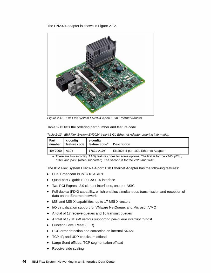
The EN2024 adapter is shown in Figure 2-12.
Figure 2-12 IBM Flex System EN2024 4-port 1 Gb Ethernet Adapter
Table 2-13 lists the ordering part number and feature code.
Table 2-13 IBM Flex System EN2024 4-port 1 Gb Ethernet Adapter ordering information
The IBM Flex System EN2024 4-port 1Gb Ethernet Adapter has the following features:
� Dual Broadcom BCM5718 ASICs
� Quad-port Gigabit 1000BASE-X interface
� Two PCI Express 2.0 x1 host interfaces, one per ASIC
� Full-duplex (FDX) capability, which enables simultaneous transmission and reception of data on the Ethernet network
� MSI and MSI-X capabilities, up to 17 MSI-X vectors
� I/O virtualization support for VMware NetQueue, and Microsoft VMQ
� A total of 17 receive queues and 16 transmit queues
� A total of 17 MSI-X vectors supporting per-queue interrupt to host
� Function Level Reset (FLR)
� ECC error detection and correction on internal SRAM
� TCP, IP, and UDP checksum offload
� Large Send offload, TCP segmentation offload
� Receive-side scaling
Partnumber
x-configfeature code
e-config feature codea
a. There are two e-config (AAS) feature codes for some options. The first is for the x240, p24L, p260, and p460 (when supported). The second is for the x220 and x440.
Description
49Y7900 A10Y 1763 / A10Y EN2024 4-port 1Gb Ethernet Adapter
46 IBM Flex System Networking in an Enterprise Data Center
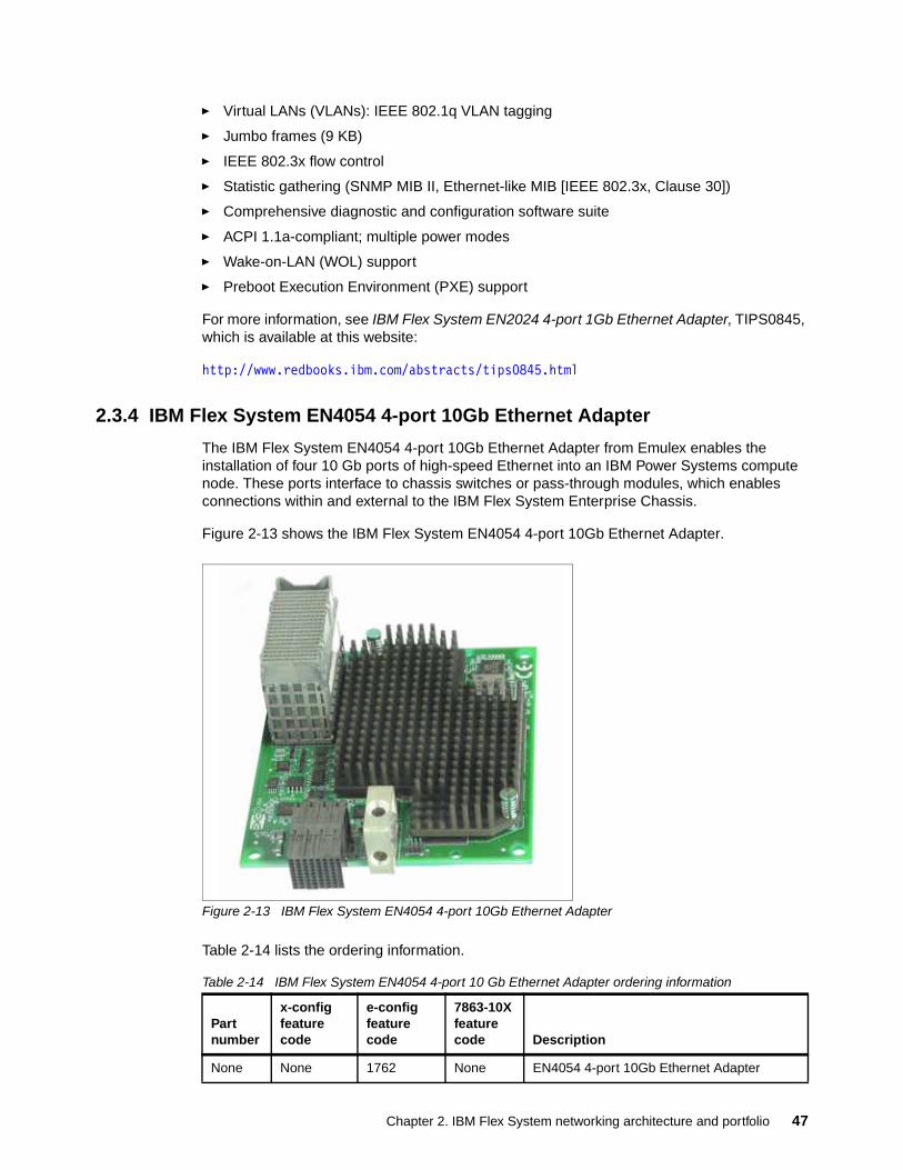
� Virtual LANs (VLANs): IEEE 802.1q VLAN tagging
� Jumbo frames (9 KB)
� IEEE 802.3x flow control
� Statistic gathering (SNMP MIB II, Ethernet-like MIB [IEEE 802.3x, Clause 30])
� Comprehensive diagnostic and configuration software suite
� ACPI 1.1a-compliant; multiple power modes
� Wake-on-LAN (WOL) support
� Preboot Execution Environment (PXE) support
For more information, see IBM Flex System EN2024 4-port 1Gb Ethernet Adapter, TIPS0845, which is available at this website:
http://www.redbooks.ibm.com/abstracts/tips0845.html
2.3.4 IBM Flex System EN4054 4-port 10Gb Ethernet Adapter
The IBM Flex System EN4054 4-port 10Gb Ethernet Adapter from Emulex enables the installation of four 10 Gb ports of high-speed Ethernet into an IBM Power Systems compute node. These ports interface to chassis switches or pass-through modules, which enables connections within and external to the IBM Flex System Enterprise Chassis.
Figure 2-13 shows the IBM Flex System EN4054 4-port 10Gb Ethernet Adapter.
Figure 2-13 IBM Flex System EN4054 4-port 10Gb Ethernet Adapter
Table 2-14 lists the ordering information.
Table 2-14 IBM Flex System EN4054 4-port 10 Gb Ethernet Adapter ordering information
Partnumber
x-config feature code
e-config feature code
7863-10Xfeature code Description
None None 1762 None EN4054 4-port 10Gb Ethernet Adapter
Chapter 2. IBM Flex System networking architecture and portfolio 47
The IBM Flex System EN4054 4-port 10Gb Ethernet Adapter has the following features and specifications:
� Four-port 10 Gb Ethernet adapter
� Dual-ASIC Emulex BladeEngine 3 controller
� Connection to either 1 Gb or 10 Gb data center infrastructure (1 Gb and 10 Gb auto-negotiation)
� PCI Express 3.0 x8 host interface (The p260 and p460 support PCI Express 2.0 x8.)
� Full-duplex capability
� Bus-mastering support
� Direct memory access (DMA) support
� PXE support
� IPv4/IPv6 TCP and UDP checksum offload:
– Large send offload – Large receive offload – Receive-Side Scaling (RSS) – IPv4 TCP Chimney offload – TCP Segmentation offload
� VLAN insertion and extraction
� Jumbo frames up to 9000 bytes
� Load balancing and failover support, including adapter fault tolerance (AFT), switch fault tolerance (SFT), adaptive load balancing (ALB), teaming support, and IEEE 802.3ad
� Enhanced Ethernet (draft):
– Enhanced Transmission Selection (ETS) (P802.1Qaz)
– Priority-based Flow Control (PFC) (P802.1Qbb)
– Data Center Bridging Capabilities eXchange Protocol, CIN-DCBX, and CEE-DCBX (P802.1Qaz)
� Supports Serial over LAN (SoL)
For more information, see IBM Flex System CN4054 10Gb Virtual Fabric Adapter and EN4054 4-port 10Gb Ethernet Adapter, TIPS0868, which is available at this website:
http://www.redbooks.ibm.com/abstracts/tips0868.html?Open
2.3.5 IBM Flex System EN4132 2-port 10Gb Ethernet Adapter
The IBM Flex System EN4132 2-port 10Gb Ethernet Adapter from Mellanox provides the highest performing and most flexible interconnect solution for servers that are used in Enterprise Data Centers, high-performance computing, and embedded environments.
48 IBM Flex System Networking in an Enterprise Data Center
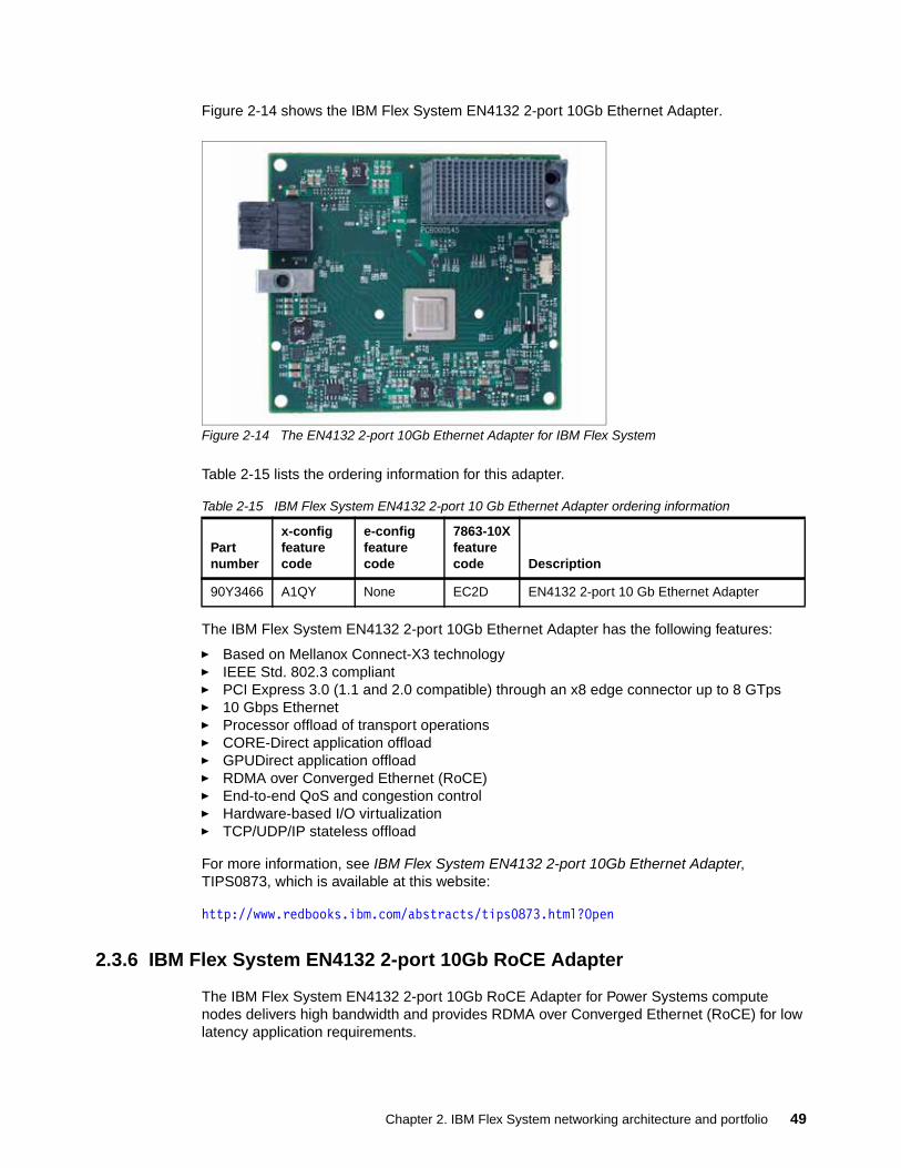
Figure 2-14 shows the IBM Flex System EN4132 2-port 10Gb Ethernet Adapter.
Figure 2-14 The EN4132 2-port 10Gb Ethernet Adapter for IBM Flex System
Table 2-15 lists the ordering information for this adapter.
Table 2-15 IBM Flex System EN4132 2-port 10 Gb Ethernet Adapter ordering information
The IBM Flex System EN4132 2-port 10Gb Ethernet Adapter has the following features:
� Based on Mellanox Connect-X3 technology� IEEE Std. 802.3 compliant� PCI Express 3.0 (1.1 and 2.0 compatible) through an x8 edge connector up to 8 GTps� 10 Gbps Ethernet� Processor offload of transport operations� CORE-Direct application offload� GPUDirect application offload� RDMA over Converged Ethernet (RoCE)� End-to-end QoS and congestion control� Hardware-based I/O virtualization� TCP/UDP/IP stateless offload
For more information, see IBM Flex System EN4132 2-port 10Gb Ethernet Adapter, TIPS0873, which is available at this website:
http://www.redbooks.ibm.com/abstracts/tips0873.html?Open
2.3.6 IBM Flex System EN4132 2-port 10Gb RoCE Adapter
The IBM Flex System EN4132 2-port 10Gb RoCE Adapter for Power Systems compute nodes delivers high bandwidth and provides RDMA over Converged Ethernet (RoCE) for low latency application requirements.
Partnumber
x-config feature code
e-config feature code
7863-10Xfeature code Description
90Y3466 A1QY None EC2D EN4132 2-port 10 Gb Ethernet Adapter
Chapter 2. IBM Flex System networking architecture and portfolio 49
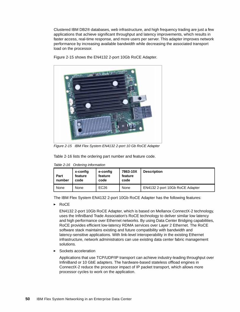
Clustered IBM DB2® databases, web infrastructure, and high frequency trading are just a few applications that achieve significant throughput and latency improvements, which results in faster access, real-time response, and more users per server. This adapter improves network performance by increasing available bandwidth while decreasing the associated transport load on the processor.
Figure 2-15 shows the EN4132 2-port 10Gb RoCE Adapter.
Figure 2-15 IBM Flex System EN4132 2-port 10 Gb RoCE Adapter
Table 2-16 lists the ordering part number and feature code.
Table 2-16 Ordering information
The IBM Flex System EN4132 2-port 10Gb RoCE Adapter has the following features:
� RoCE
EN4132 2-port 10Gb RoCE Adapter, which is based on Mellanox ConnectX-2 technology, uses the InfiniBand Trade Association's RoCE technology to deliver similar low latency and high performance over Ethernet networks. By using Data Center Bridging capabilities, RoCE provides efficient low-latency RDMA services over Layer 2 Ethernet. The RoCE software stack maintains existing and future compatibility with bandwidth and latency-sensitive applications. With link-level interoperability in the existing Ethernet infrastructure, network administrators can use existing data center fabric management solutions.
� Sockets acceleration
Applications that use TCP/UDP/IP transport can achieve industry-leading throughput over InfiniBand or 10 GbE adapters. The hardware-based stateless offload engines in ConnectX-2 reduce the processor impact of IP packet transport, which allows more processor cycles to work on the application.
Partnumber
x-config feature code
e-config feature code
7863-10Xfeature code
Description
None None EC26 None EN4132 2-port 10Gb RoCE Adapter
50 IBM Flex System Networking in an Enterprise Data Center
� I/O virtualization
ConnectX-2 with Virtual Intelligent Queuing (Virtual-IQ) technology provides dedicated adapter resources and ensured isolation and protection for virtual machines within the server. I/O virtualization with ConnectX-2 gives data center managers better server usage while it reduces cost, power, and cable complexity.
The IBM Flex System EN4132 2-port 10Gb RoCE Adapter has the following specifications (which are based on Mellanox Connect-X2 technology):
� PCI Express 2.0 (1.1 compatible) through an x8 edge connector with up to 5 GTps� 10 Gbps Ethernet� Processor offload of transport operations� CORE-Direct application offload� GPUDirect application offload� RoCE� End-to-end QoS and congestion control� Hardware-based I/O virtualization� TCP/UDP/IP stateless off-load� Ethernet encapsulation (EoIB)� 128 MAC/VLAN addresses per port
For more information, see IBM Flex System EN4132 2-port 10Gb RoCE Adapter, TIPS0913, which is available at this website:
http://www.redbooks.ibm.com/abstracts/tips0913.html
2.3.7 IBM Flex System EN6132 2-port 40Gb Ethernet Adapter
The IBM Flex System EN6132 2-port 40Gb Ethernet Adapter provides a high-performance, flexible interconnect solution for servers that are used in the enterprise data center, high-performance computing, and embedded environments. The IBM Flex System EN6132 2-port 40Gb Ethernet Adapter is based on Mellanox ConnectX-3 ASIC. It includes more features such as RDMA and RoCE technologies that help provide acceleration and low latency for specialized applications. This adapter works with the IBM Flex System 40Gb Ethernet Switch to deliver industry-leading Ethernet bandwidth, which is ideal for high-performance computing.
Chapter 2. IBM Flex System networking architecture and portfolio 51
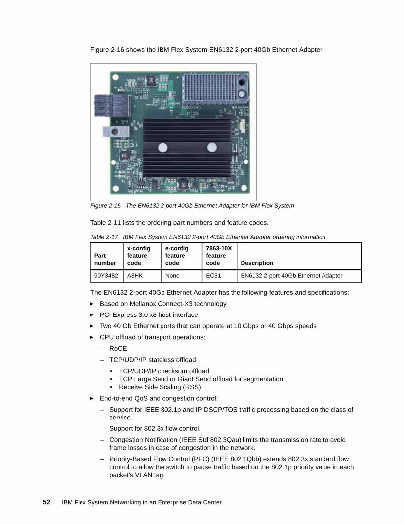
Figure 2-16 shows the IBM Flex System EN6132 2-port 40Gb Ethernet Adapter.
Figure 2-16 The EN6132 2-port 40Gb Ethernet Adapter for IBM Flex System
Table 2-11 lists the ordering part numbers and feature codes.
Table 2-17 IBM Flex System EN6132 2-port 40Gb Ethernet Adapter ordering information
The EN6132 2-port 40Gb Ethernet Adapter has the following features and specifications:
� Based on Mellanox Connect-X3 technology
� PCI Express 3.0 x8 host-interface
� Two 40 Gb Ethernet ports that can operate at 10 Gbps or 40 Gbps speeds
� CPU offload of transport operations:
– RoCE
– TCP/UDP/IP stateless offload:
• TCP/UDP/IP checksum offload• TCP Large Send or Giant Send offload for segmentation• Receive Side Scaling (RSS)
� End-to-end QoS and congestion control:
– Support for IEEE 802.1p and IP DSCP/TOS traffic processing based on the class of service.
– Support for 802.3x flow control.
– Congestion Notification (IEEE Std 802.3Qau) limits the transmission rate to avoid frame losses in case of congestion in the network.
– Priority-Based Flow Control (PFC) (IEEE 802.1Qbb) extends 802.3x standard flow control to allow the switch to pause traffic based on the 802.1p priority value in each packet’s VLAN tag.
Partnumber
x-configfeature code
e-config feature code
7863-10Xfeature code Description
90Y3482 A3HK None EC31 EN6132 2-port 40Gb Ethernet Adapter
52 IBM Flex System Networking in an Enterprise Data Center
– Enhanced Transmission Selection (ETS) (IEEE 802.1Qaz) provides a method for allocating link bandwidth based on the 802.1p priority value in each packet’s VLAN tag.
� Hardware-based I/O virtualization
� Jumbo frame support (up to 10 KB)
� 802.1Q VLAN tagging
� NIC teaming and failover (static and LACP)
� Support for Wake on LAN (WoL)
For more information, see IBM Flex System EN6132 2-port 40Gb Ethernet Adapter, TIPS0912, which is available at this website:
http://www.redbooks.ibm.com/abstracts/tips0912.html?Open
Chapter 2. IBM Flex System networking architecture and portfolio 53

54 IBM Flex System Networking in an Enterprise Data Center
Chapter 3. IBM Flex System data center network design basics
This chapter covers basic and advanced networking techniques that can be deployed with IBM Flex System platform in a data center to meet availability, performance, scalability, and systems management goals.
The following topics are included in this chapter:
� Choosing the Ethernet switch I/O module� Virtual local area networks� Scalability and performance� High availability� FCoE capabilities� Virtual Fabric vNIC solution capabilities� Unified Fabric Port feature� Easy Connect concept� Stacking feature� Openflow support� 802.1Qbg Edge Virtual Bridge support� SPAR feature� Management� Summary and conclusions
3
© Copyright IBM Corp. 2013. All rights reserved. 55
3.1 Choosing the Ethernet switch I/O module
Selecting the Ethernet I/O module that is best for an environment is a process unique to each client. The following factors should be considered when you are deciding which Ethernet model is right for a specific environment:
� The first decision is regarding speed requirements. Do you only need 1Gb connectivity to the servers, or is 10Gb to the servers a requirement?
If there is no immediate need for 10 Gb to the servers, there are no plans to upgrade to 10 Gb in the foreseeable future, and you have no need for any of the advanced features offered in the 10 Gb products, the EN2092 1Gb Ethernet Switch is a possible solution.
If you need a solution that has 10G to the server, is not apparent to the network, only has a single link for each compute node for each I/O module, and requires direct connections from the compute node to the external ToR switch, the EN4091 10Gb Ethernet Pass-thru is a viable option.
If you need 10Gb today or know you need 10Gb in the near future, have need of more than one 10G link from each switch bay to each compute node, or need any of the features that are associated with 10Gb server interfaces, such as FCoE and switched-based vNIC support, you have a choice of EN4093R 10Gb Scalable Switch, the CN4093 10Gb Converged Scalable Switch or the SI4093 System Interconnect Module.
Consider the following factors when you are selecting between the EN4093R 10Gb Scalable Switch, the CN4093 10Gb Converged Scalable Switch, and the SI4093 System Interconnect Module:
� If you require Fibre Channel Forwarder (FCF) services within the Enterprise Chassis, or native Fibre Channel uplinks from the 10G switch, the CN4093 10Gb Converged Scalable Switch is the correct choice.
� If you do not require FCF services or native Fibre Channel ports on the 10G switch, but need the maximum number of 10G uplinks without purchasing an extra license, support for FCoE transit capabilities and the most feature-rich solution the EN4093R 10Gb Scalable Switch is a good choice.
� If you require ready for use not apparent operation (minimal to no configuration on the switch), and do not need any L3 support or other advanced features (and know that more advanced functions are not needed), the SI4093 System Interconnect Module is a potential choice.
There are more criteria involved because each environment has its own unique attributes. However, the criteria reviewed in this section are a good starting point in the decision making process.
56 IBM Flex System Networking in an Enterprise Data Center
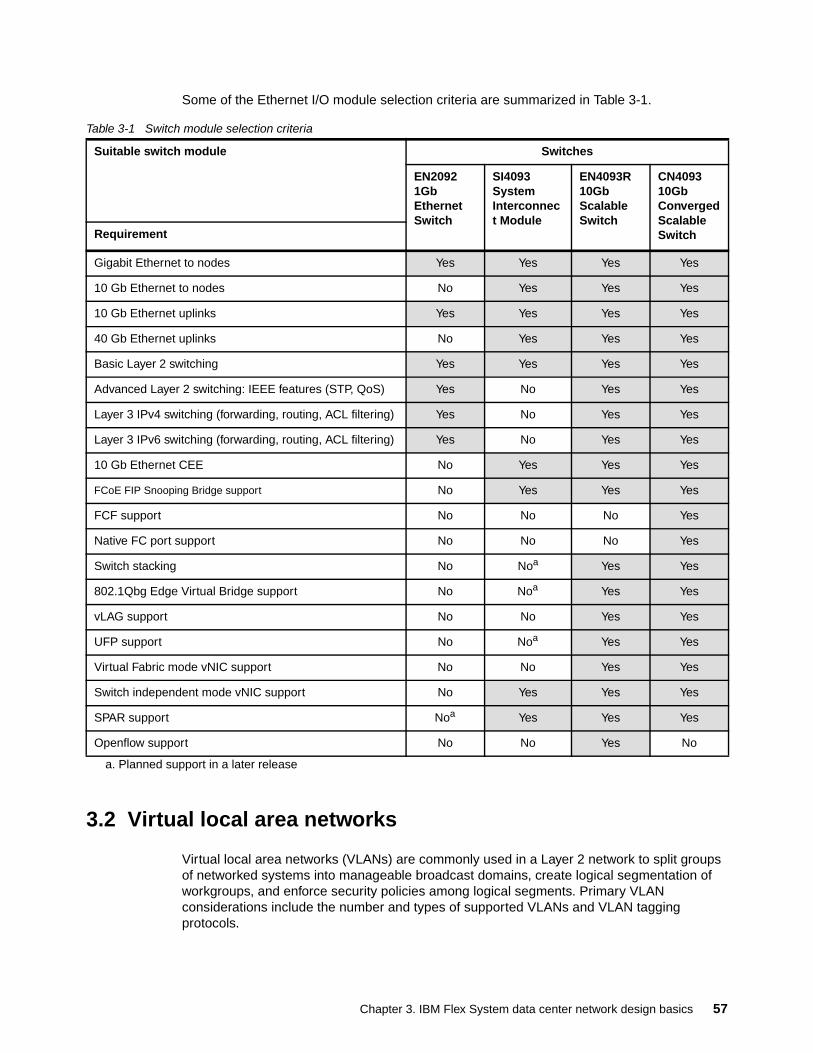
Some of the Ethernet I/O module selection criteria are summarized in Table 3-1.
Table 3-1 Switch module selection criteria
3.2 Virtual local area networks
Virtual local area networks (VLANs) are commonly used in a Layer 2 network to split groups of networked systems into manageable broadcast domains, create logical segmentation of workgroups, and enforce security policies among logical segments. Primary VLAN considerations include the number and types of supported VLANs and VLAN tagging protocols.
Suitable switch module Switches
EN2092 1Gb Ethernet Switch
SI4093 System Interconnect Module
EN4093R 10Gb Scalable Switch
CN4093 10Gb Converged Scalable SwitchRequirement
Gigabit Ethernet to nodes Yes Yes Yes Yes
10 Gb Ethernet to nodes No Yes Yes Yes
10 Gb Ethernet uplinks Yes Yes Yes Yes
40 Gb Ethernet uplinks No Yes Yes Yes
Basic Layer 2 switching Yes Yes Yes Yes
Advanced Layer 2 switching: IEEE features (STP, QoS) Yes No Yes Yes
Layer 3 IPv4 switching (forwarding, routing, ACL filtering) Yes No Yes Yes
Layer 3 IPv6 switching (forwarding, routing, ACL filtering) Yes No Yes Yes
10 Gb Ethernet CEE No Yes Yes Yes
FCoE FIP Snooping Bridge support No Yes Yes Yes
FCF support No No No Yes
Native FC port support No No No Yes
Switch stacking No Noa
a. Planned support in a later release
Yes Yes
802.1Qbg Edge Virtual Bridge support No Noa Yes Yes
vLAG support No No Yes Yes
UFP support No Noa Yes Yes
Virtual Fabric mode vNIC support No No Yes Yes
Switch independent mode vNIC support No Yes Yes Yes
SPAR support Noa Yes Yes Yes
Openflow support No No Yes No
Chapter 3. IBM Flex System data center network design basics 57
The EN4093R 10Gb Scalable Switch, CN4093 10Gb Converged Scalable Switch, and EN2092 1Gb Ethernet Switch have the following VLAN-related features (unless noted):
� Support for 4094 active VLANs, out of the range of 1 - 4094
Some VLANs might be reserved when certain features (for example, stacking, UFP) are enabled.
� IEEE 802.1Q for VLAN tagging on links (also called trunking by some vendors)
Support for tagged or untagged native VLAN.
� Port-based VLANs
� Protocol-based VLANs
� Spanning-tree per VLAN (Per VLAN Rapid Spanning-tree)
This is the default Spanning-tree mode for the EN2092 1Gb Ethernet Switch, EN4093R 10Gb Scalable Switch and CN4093 10Gb Converged Scalable Switch. The SI4093 System Interconnect Module does not support Spanning-tree.
Limited to 127 instances of Spanning-tree. VLANs added after 127 operational instances are placed into Spanning-tree instance 1.
� 802.1x Guest VLANs
� VLAN Maps for ACLs
� VLAN-based port mirroring
The SI4093 System Interconnect Module by default is VLAN not apparent, and passes packets through the switch regardless of tagged or untagged, so the number of VLANs that are supported is limited to whatever the compute node OS and the upstream network support. When it is changed from its default mode to SPAR local domain mode, it supports up to 250 VLANs, but does not support Spanning-tree because it prohibits a user from creating a loop.
Specific to 802.1Q VLAN tagging, this feature is critical to maintain VLAN separation when packets in multiple VLANs must traverse a common link between devices. Without a tagging protocol, such as 802.1Q, maintaining VLAN separation between devices can be accomplished through a separate link for each VLAN, a less than optimal solution.
The need for 802.1Q VLAN tagging is not relegated only to networking devices. It is also supported and frequently used on end nodes, and is implemented differently by various operating systems (OSs). For example, for Windows Server 2008 and earlier, a vendor driver was needed to subdivide the physical interface into logical NICs, with each logical NIC set for a specific VLAN. Typically, this setup is part of the teaming software from the NIC vendor. Windows Server 2012 has tagging option natively available.
For Linux, tagging is done by creating sub-interfaces of a physical or logical NIC, such as eth0.10 for VLAN 10 on physical interface eth0.
Important: The EN4093R 10Gb Scalable Switch and CN4093 10Gb Converged Scalable Switch under certain configurations (for example, Easy Connect mode) are not apparent to VLAN tags and act as a VLAN tag pass-through, so the limitations that are described here do not apply in these modes.
Important: In rare cases, there are some older non-standards based tagging protocols that are used by vendors. These protocols are not compatible with 802.1Q or the Enterprise Chassis switching products.
58 IBM Flex System Networking in an Enterprise Data Center
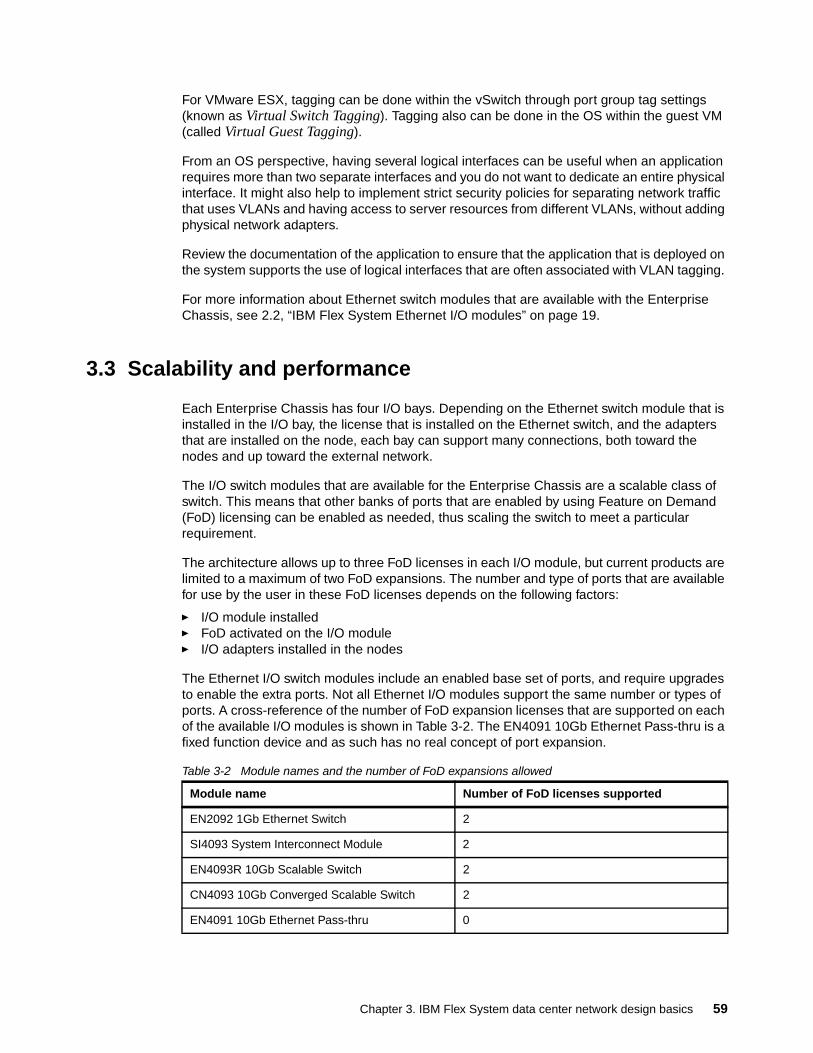
For VMware ESX, tagging can be done within the vSwitch through port group tag settings (known as Virtual Switch Tagging). Tagging also can be done in the OS within the guest VM (called Virtual Guest Tagging).
From an OS perspective, having several logical interfaces can be useful when an application requires more than two separate interfaces and you do not want to dedicate an entire physical interface. It might also help to implement strict security policies for separating network traffic that uses VLANs and having access to server resources from different VLANs, without adding physical network adapters.
Review the documentation of the application to ensure that the application that is deployed on the system supports the use of logical interfaces that are often associated with VLAN tagging.
For more information about Ethernet switch modules that are available with the Enterprise Chassis, see 2.2, “IBM Flex System Ethernet I/O modules” on page 19.
3.3 Scalability and performance
Each Enterprise Chassis has four I/O bays. Depending on the Ethernet switch module that is installed in the I/O bay, the license that is installed on the Ethernet switch, and the adapters that are installed on the node, each bay can support many connections, both toward the nodes and up toward the external network.
The I/O switch modules that are available for the Enterprise Chassis are a scalable class of switch. This means that other banks of ports that are enabled by using Feature on Demand (FoD) licensing can be enabled as needed, thus scaling the switch to meet a particular requirement.
The architecture allows up to three FoD licenses in each I/O module, but current products are limited to a maximum of two FoD expansions. The number and type of ports that are available for use by the user in these FoD licenses depends on the following factors:
� I/O module installed� FoD activated on the I/O module� I/O adapters installed in the nodes
The Ethernet I/O switch modules include an enabled base set of ports, and require upgrades to enable the extra ports. Not all Ethernet I/O modules support the same number or types of ports. A cross-reference of the number of FoD expansion licenses that are supported on each of the available I/O modules is shown in Table 3-2. The EN4091 10Gb Ethernet Pass-thru is a fixed function device and as such has no real concept of port expansion.
Table 3-2 Module names and the number of FoD expansions allowed
Module name Number of FoD licenses supported
EN2092 1Gb Ethernet Switch 2
SI4093 System Interconnect Module 2
EN4093R 10Gb Scalable Switch 2
CN4093 10Gb Converged Scalable Switch 2
EN4091 10Gb Ethernet Pass-thru 0
Chapter 3. IBM Flex System data center network design basics 59
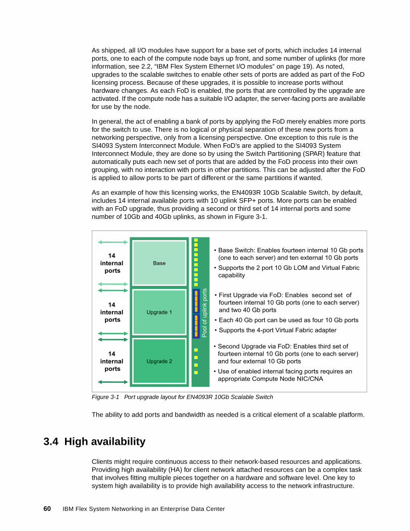
As shipped, all I/O modules have support for a base set of ports, which includes 14 internal ports, one to each of the compute node bays up front, and some number of uplinks (for more information, see 2.2, “IBM Flex System Ethernet I/O modules” on page 19). As noted, upgrades to the scalable switches to enable other sets of ports are added as part of the FoD licensing process. Because of these upgrades, it is possible to increase ports without hardware changes. As each FoD is enabled, the ports that are controlled by the upgrade are activated. If the compute node has a suitable I/O adapter, the server-facing ports are available for use by the node.
In general, the act of enabling a bank of ports by applying the FoD merely enables more ports for the switch to use. There is no logical or physical separation of these new ports from a networking perspective, only from a licensing perspective. One exception to this rule is the SI4093 System Interconnect Module. When FoD’s are applied to the SI4093 System Interconnect Module, they are done so by using the Switch Partitioning (SPAR) feature that automatically puts each new set of ports that are added by the FoD process into their own grouping, with no interaction with ports in other partitions. This can be adjusted after the FoD is applied to allow ports to be part of different or the same partitions if wanted.
As an example of how this licensing works, the EN4093R 10Gb Scalable Switch, by default, includes 14 internal available ports with 10 uplink SFP+ ports. More ports can be enabled with an FoD upgrade, thus providing a second or third set of 14 internal ports and some number of 10Gb and 40Gb uplinks, as shown in Figure 3-1.
Figure 3-1 Port upgrade layout for EN4093R 10Gb Scalable Switch
The ability to add ports and bandwidth as needed is a critical element of a scalable platform.
3.4 High availability
Clients might require continuous access to their network-based resources and applications. Providing high availability (HA) for client network attached resources can be a complex task that involves fitting multiple pieces together on a hardware and software level. One key to system high availability is to provide high availability access to the network infrastructure.
Base
Upgrade 1
Upgrade 2
• Base Switch: Enables fourteen internal 10 Gb ports
(one to each server) and ten external 10 Gb ports
• Supports the 2 port 10 Gb LOM and Virtual Fabric
capability
14internal
ports
Po
ol o
f u
plin
k p
ort
s
• First Upgrade via FoD: Enables second set of
fourteen internal 10 Gb ports (one to each server)
and two 40 Gb ports
• Each 40 Gb port can be used as four 10 Gb ports
• Supports the 4-port Virtual Fabric adapter
• Second Upgrade via FoD: Enables third set of
fourteen internal 10 Gb ports (one to each server)
and four external 10 Gb ports
• Use of enabled internal facing ports requires an
appropriate Compute Node NIC/CNA
14internal
ports
14internal
ports
60 IBM Flex System Networking in an Enterprise Data Center
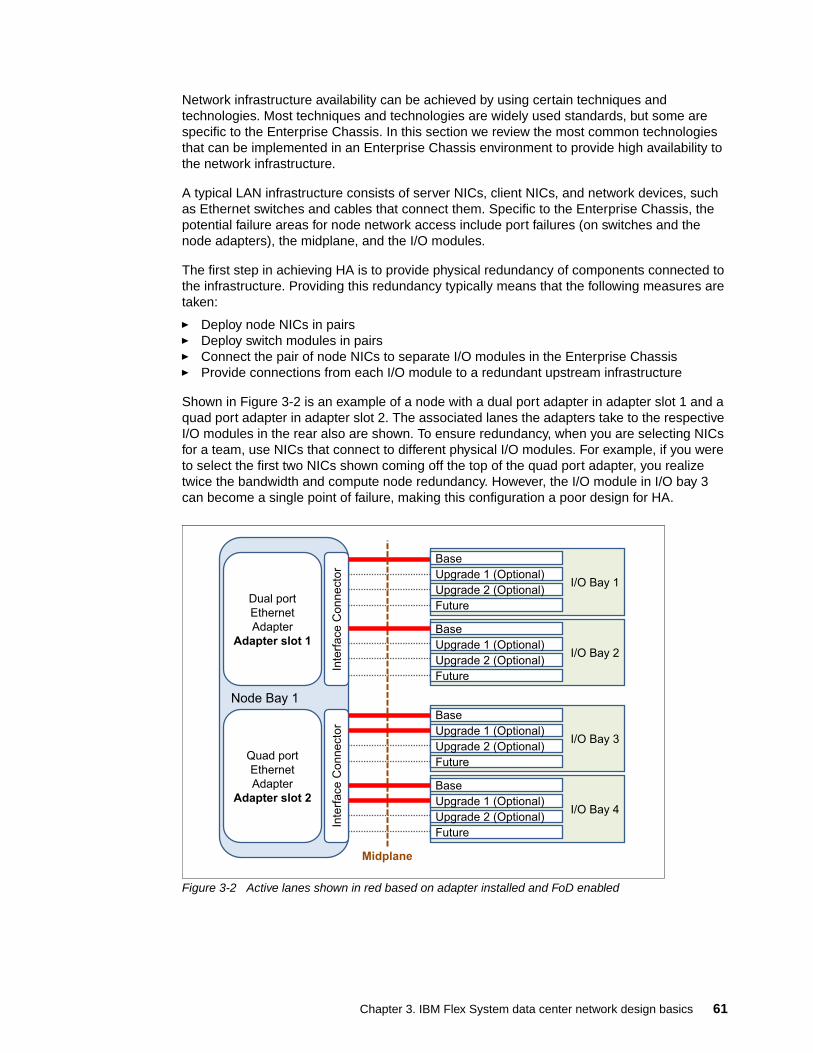
Network infrastructure availability can be achieved by using certain techniques and technologies. Most techniques and technologies are widely used standards, but some are specific to the Enterprise Chassis. In this section we review the most common technologies that can be implemented in an Enterprise Chassis environment to provide high availability to the network infrastructure.
A typical LAN infrastructure consists of server NICs, client NICs, and network devices, such as Ethernet switches and cables that connect them. Specific to the Enterprise Chassis, the potential failure areas for node network access include port failures (on switches and the node adapters), the midplane, and the I/O modules.
The first step in achieving HA is to provide physical redundancy of components connected to the infrastructure. Providing this redundancy typically means that the following measures are taken:
� Deploy node NICs in pairs� Deploy switch modules in pairs� Connect the pair of node NICs to separate I/O modules in the Enterprise Chassis� Provide connections from each I/O module to a redundant upstream infrastructure
Shown in Figure 3-2 is an example of a node with a dual port adapter in adapter slot 1 and a quad port adapter in adapter slot 2. The associated lanes the adapters take to the respective I/O modules in the rear also are shown. To ensure redundancy, when you are selecting NICs for a team, use NICs that connect to different physical I/O modules. For example, if you were to select the first two NICs shown coming off the top of the quad port adapter, you realize twice the bandwidth and compute node redundancy. However, the I/O module in I/O bay 3 can become a single point of failure, making this configuration a poor design for HA.
Figure 3-2 Active lanes shown in red based on adapter installed and FoD enabled
Node Bay 1
Inte
rface C
onnecto
r
I/O Bay 1
Base
Upgrade 1 (Optional)
Upgrade 2 (Optional)
Future
I/O Bay 2
Base
Upgrade 1 (Optional)
Upgrade 2 (Optional)
Future
Inte
rface C
onnecto
r
I/O Bay 3
Base
Upgrade 1 (Optional)
Upgrade 2 (Optional)
Future
I/O Bay 4
Base
Upgrade 1 (Optional)
Upgrade 2 (Optional)
Future
Midplane
Dual port
Ethernet
Adapter
Adapter slot 1
Quad port
Ethernet
Adapter
Adapter slot 2
Chapter 3. IBM Flex System data center network design basics 61
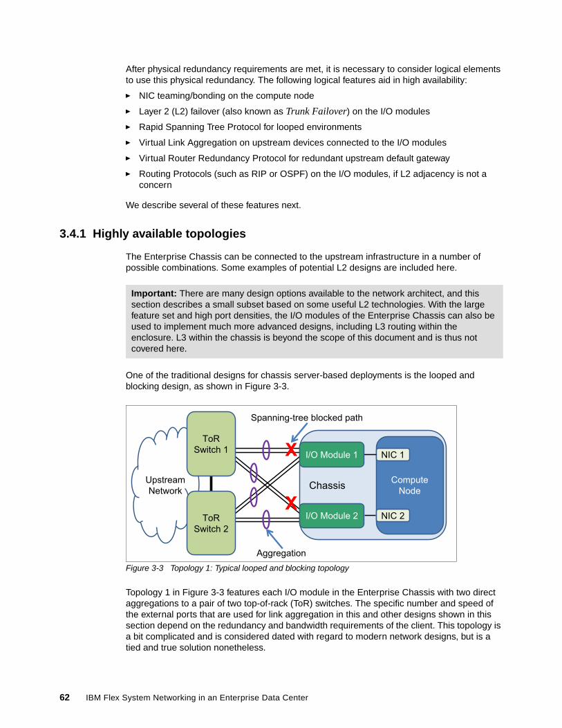
After physical redundancy requirements are met, it is necessary to consider logical elements to use this physical redundancy. The following logical features aid in high availability:
� NIC teaming/bonding on the compute node
� Layer 2 (L2) failover (also known as Trunk Failover) on the I/O modules
� Rapid Spanning Tree Protocol for looped environments
� Virtual Link Aggregation on upstream devices connected to the I/O modules
� Virtual Router Redundancy Protocol for redundant upstream default gateway
� Routing Protocols (such as RIP or OSPF) on the I/O modules, if L2 adjacency is not a concern
We describe several of these features next.
3.4.1 Highly available topologies
The Enterprise Chassis can be connected to the upstream infrastructure in a number of possible combinations. Some examples of potential L2 designs are included here.
One of the traditional designs for chassis server-based deployments is the looped and blocking design, as shown in Figure 3-3.
Figure 3-3 Topology 1: Typical looped and blocking topology
Topology 1 in Figure 3-3 features each I/O module in the Enterprise Chassis with two direct aggregations to a pair of two top-of-rack (ToR) switches. The specific number and speed of the external ports that are used for link aggregation in this and other designs shown in this section depend on the redundancy and bandwidth requirements of the client. This topology is a bit complicated and is considered dated with regard to modern network designs, but is a tied and true solution nonetheless.
Important: There are many design options available to the network architect, and this section describes a small subset based on some useful L2 technologies. With the large feature set and high port densities, the I/O modules of the Enterprise Chassis can also be used to implement much more advanced designs, including L3 routing within the enclosure. L3 within the chassis is beyond the scope of this document and is thus not covered here.
ChassisCompute
Node
NIC 1
NIC 2
Upstream
Network
ToR
Switch 2
ToR
Switch 1
Aggregation
X
X
Spanning-tree blocked path
I/O Module 1
I/O Module 2
62 IBM Flex System Networking in an Enterprise Data Center
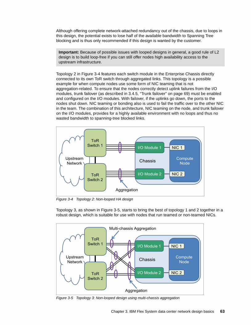
Although offering complete network-attached redundancy out of the chassis, due to loops in this design, the potential exists to lose half of the available bandwidth to Spanning Tree blocking and is thus only recommended if this design is wanted by the customer.
Topology 2 in Figure 3-4 features each switch module in the Enterprise Chassis directly connected to its own ToR switch through aggregated links. This topology is a possible example for when compute nodes use some form of NIC teaming that is not aggregation-related. To ensure that the nodes correctly detect uplink failures from the I/O modules, trunk failover (as described in 3.4.5, “Trunk failover” on page 69) must be enabled and configured on the I/O modules. With failover, if the uplinks go down, the ports to the nodes shut down. NIC teaming or bonding also is used to fail the traffic over to the other NIC in the team. The combination of this architecture, NIC teaming on the node, and trunk failover on the I/O modules, provides for a highly available environment with no loops and thus no wasted bandwidth to spanning-tree blocked links.
Figure 3-4 Topology 2: Non-looped HA design
Topology 3, as shown in Figure 3-5, starts to bring the best of topology 1 and 2 together in a robust design, which is suitable for use with nodes that run teamed or non-teamed NICs.
Figure 3-5 Topology 3: Non-looped design using multi-chassis aggregation
Important: Because of possible issues with looped designs in general, a good rule of L2 design is to build loop-free if you can still offer nodes high availability access to the upstream infrastructure.
ChassisCompute
Node
NIC 1
NIC 2
Upstream
Network
ToR
Switch 2
ToR
Switch 1I/O Module 1
I/O Module 2
Aggregation
ChassisCompute
Node
NIC 1
NIC 2
Upstream
Network
ToR
Switch 2
ToR
Switch 1
Multi-chassis Aggregation
I/O Module 1
I/O Module 2
Aggregation
Chapter 3. IBM Flex System data center network design basics 63
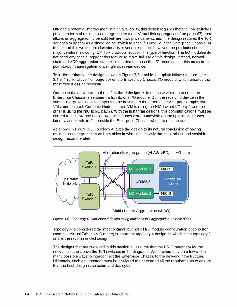
Offering a potential improvement in high availability, this design requires that the ToR switches provide a form of multi-chassis aggregation (see “Virtual link aggregations” on page 67), that allows an aggregation to be split between two physical switches. The design requires the ToR switches to appear as a single logical switch to each I/O module in the Enterprise Chassis. At the time of this writing, this functionality is vendor-specific; however, the products of most major vendors, including IBM ToR products, support this type of function. The I/O modules do not need any special aggregation feature to make full use of this design. Instead, normal static or LACP aggregation support is needed because the I/O modules see this as a simple point-to-point aggregation to a single upstream device.
To further enhance the design shown in Figure 3-5, enable the uplink failover feature (see 3.4.5, “Trunk failover” on page 69) on the Enterprise Chassis I/O module, which ensures the most robust design possible.
One potential draw back to these first three designs is in the case where a node in the Enterprise Chassis is sending traffic into one I/O module. But, the receiving device in the same Enterprise Chassis happens to be hashing to the other I/O device (for example, two VMs, one on each Compute Node, but one VM is using the NIC toward I/O bay 1 and the other is using the NIC to I/O bay 2). With the first three designs, this communications must be carried to the ToR and back down, which uses extra bandwidth on the uplinks, increases latency, and sends traffic outside the Enterprise Chassis when there is no need.
As shown in Figure 3-6, Topology 4 takes the design to its natural conclusion of having multi-chassis aggregation on both sides in what is ultimately the most robust and scalable design recommended.
Figure 3-6 Topology 4: Non-looped design using multi-chassis aggregation on both sides
Topology 4 is considered the most optimal, but not all I/O module configuration options (for example, Virtual Fabric vNIC mode) support the topology 4 design, in which case topology 3 or 2 is the recommended design.
The designs that are reviewed in this section all assume that the L2/L3 boundary for the network is at or above the ToR switches in the diagrams. We touched only on a few of the many possible ways to interconnect the Enterprise Chassis to the network infrastructure. Ultimately, each environment must be analyzed to understand all the requirements to ensure that the best design is selected and deployed.
ChassisCompute
Node
NIC 1
NIC 2
Upstream
Network
ToR
Switch 2
ToR
Switch 1
Multi-chassis Aggregation (vLAG, vPC, mLAG, etc)
I/O Module 1
I/O Module 2
Multi-chassis Aggregation (vLAG)
64 IBM Flex System Networking in an Enterprise Data Center
3.4.2 Spanning Tree
Spanning Tree is defined in the IEEE specification 802.1D. The primary goal of Spanning Tree is to ensure a loop-free design in an L2 network. Loops cannot be allowed to exist in an L2 network because there is no mechanism in an L2 frame to aid in the detection and prevention of looping packets, such as a time to live field or a hop count (all part of the L3 header portion of some packet headers, but not seen by L2 switching devices). Packets might loop indefinitely and use bandwidth that can be used for other purposes. Ultimately, an L2-looped network eventually fails as broadcast and multicast packets rapidly multiply through the loop.
The entire process that is used by Spanning Tree to control loops is beyond the scope of this publication. In its simplest terms, Spanning Tree controls loops by exchanging Bridge Protocol Data Units (BPDUs) and building a tree that blocks redundant paths until they might be needed, for example, if the path that is currently selected for forwarding went down.
The Spanning Tree specification evolved considerably since its original release. Other standards, such as 802.1w (rapid Spanning Tree) and 802.1s (multi-instance Spanning Tree) are included in the current Spanning Tree specification, 802.1D-2004. As some features were added, other features, such as the original non-rapid Spanning Tree, are no longer part of the specification.
The EN2092 1Gb Ethernet Switch, EN4093R 10Gb Scalable Switch, and CN4093 10Gb Converged Scalable Switch all support the 802.1D specification. They also support a Cisco proprietary version of Spanning Tree called Per VLAN Rapid Spanning Tree (PVRST). The following Spanning Tree modes are supported on these modules:
� Rapid Spanning Tree (RSTP), also known as mono instance Spanning Tree� Multi-instance Spanning Tree (MSTP)� PVRST� Disabled (turns off spanning tree on the switch)
Topology 2 in Figure 3-4 on page 63 features each switch module in the Enterprise Chassis.
The default Spanning Tree for the Enterprise Chassis I/O modules is PVRST. This Spanning Tree allows seamless integration into the largest and most commonly deployed infrastructures in use today. This mode also allows for better potential load balancing of redundant links (because blocking and forwarding is determined per VLAN rather than per physical port) over RSTP, and without some of the configuration complexities that are involved with implementing an MSTP environment.
With PVRST, as VLANs are created or deleted, an instance of Spanning Tree is automatically created or deleted for each VLAN.
Other supported forms of Spanning Tree can be enabled and configured if required, thus allowing the Enterprise Chassis to be readily deployed into the most varied environments.
Important: The SI4093 System Interconnect Module does not have support for spanning-tree. It prohibits loops by restricting uplinks out of a switch partition to a single path, which makes it impossible to create a loop.
Chapter 3. IBM Flex System data center network design basics 65
3.4.3 Link aggregation
Sometimes referred to as trunking, port channel, or Etherchannel, link aggregation involves taking multiple physical links and binding them into a single common link for use between two devices. The primary purposes of aggregation are to improve HA and increase bandwidth.
Bundling the linksAlthough there are several different kinds of aggregation, the two most common and that are supported by the Enterprise Chassis I/O modules are static and Link Aggregation Control Protocol (LACP).
Static aggregation does not use any protocol to create the aggregation. Instead, static aggregation combines the ports based on the aggregation configuration applied on the ports and assumes that the other side of the connection does the same.
LACP is an IEEE standard that was defined in 802.3ad. The standard was later included in the mainline 802.3 standard but then was pulled out into the current standard 802.1AX-2008. LACP is a dynamic way of determining whether both sides of the link agree they should be aggregating.
The decision to use static or LACP is usually a question of what a client uses in their network. If there is no preference, the following considerations can be used to aid in the decision making process.
Static aggregation is the quickest and easiest way to build an aggregated link. This method also is the most stable in high-bandwidth usage environments, particularly if pause frames are exchanged.
The use of static aggregation can be advantageous in mixed vendor environments because it can help prevent possible interoperability issues. Because settings in the LACP standard do not have a recommended default, vendors can use different defaults, which can lead to unexpected interoperation. For example, the LACP Data Unit (LACPDU) timers can be set to be exchanged every 1 second or every 30 seconds. If one side is set to 1 second and one side is set to 30 seconds, the LACP aggregation can be unstable. This is not an issue with static aggregations.
Important: In rare cases, there are still some older non-standards-based aggregation protocols, such as Port Aggregation Protocol (PAgP) in use by some vendors. These protocols are not compatible with static or LACP aggregations.
Important: In some cases, static aggregation is referred to as static LACP. This term actually is a contradictory term because as it is difficult in this context to be both static and have a Control Protocol.
Important: Most vendors default to using the 30-second exchange of LACPDUs, including IBM switches. If you encounter a vendor that defaults to 1-second timers (for example, Juniper), we advise that the other vendor changes to operate with 30-second timers, rather than setting both to 1 second. This 30-second setting tends to produce a more robust aggregation as opposed to the 1-second timers.
66 IBM Flex System Networking in an Enterprise Data Center
One of the downsides to static aggregation is that it lacks a mechanism to detect if the other side is correctly configured for aggregation. So, if one side is static and the other side is not configured, configured incorrectly, or is not connected to the correct ports, it is possible to cause a network outage by bringing up the links.
Based on the information that is presented in this section, If you are sure that your links are connected to the correct ports and that both sides are configured correctly for static aggregation, static aggregation is a solid choice.
LACP has the inherent safety that a protocol brings to this process. At link up, LACPDUs are exchanged and both sides must agree they are using LACP before it attempts to bundle the links. So, in the case of misconfiguration or incorrect connections, LACP helps protect the network from an unplanned outage.
IBM has also enhanced LACP to support a feature known as suspend-port. By definition of the IEEE standard, if ports cannot bundle because the other side does not understand LACP (for example, is not configured for LACP), the ports should be treated as individual ports and remain operational. This might lead to potential issues under certain circumstances (such as if Spanning-tree was disabled). To prevent accidental loops, the suspend-port feature can hold the ports down until such time as proper LACPDU’s are exchanged and the links can be bundled. This feature also protects against certain mis-cabling or misconfiguration that might split the aggregation into multiple smaller aggregations. For more information about this feature, see the Application Guide provided for the product.
The disadvantages of using LACP are that it takes a small amount of time to negotiate the aggregation and form an aggregating link (usually under a second), and it can become unstable and unexpectedly fail in environments with heavy and continued pause frame activity.
Another factor to consider about aggregation is whether it is better to aggregate multiple low-speed links into a high-speed aggregation, or use a single high-speed link with a similar speed to all of the links in the aggregation.
If your primary goal is high availability, aggregations can offer a no-single-point-of-failure situation that a single high-speed link cannot offer.
If maximum performance and lowest possible latency are the primary goals, often a single high-speed link makes more sense. Another factor is cost. Often, one high-speed link can cost more to implement than a link that consists of an aggregation of multiple slower links.
Virtual link aggregationsAside from the standard point-to-point aggregations covered in this section, there is a technology that provides multi-chassis aggregation, sometimes called distributed aggregation or virtual link aggregation.
Under the latest IEEE specifications, an aggregation is still defined as a bundle between only two devices. By this definition, you cannot create an aggregation on one device and have the links of that aggregation connect to more than a single device on the other side of the aggregation. The use of only two devices limits the ability to offer certain robust designs.
Although the standards bodies are working on a solution that provides split aggregations across devices, most vendors devised their own version of multi-chassis aggregation. For example, Cisco has virtual Port Channel (vPC) on Nexus products, and Virtual Switch System (VSS) on the 6500 line. IBM offers virtual Link Aggregation (vLAG) on many of our ToR solutions, and on the EN4093R 10Gb Scalable Switch and CN4093 10Gb Converged Scalable Switch.
Chapter 3. IBM Flex System data center network design basics 67
The primary goals of virtual link aggregation are to overcome the limits imposed by current standards-based aggregation and provide a distributed aggregation across a pair of switches instead of a single switch.
The decisions whether to aggregate and which method of aggregation is most suitable to a specific environment are not always straightforward. But if the decision is made to aggregate, the I/O modules for the Enterprise Chassis offer the necessary wanted features to integrate into the aggregated infrastructure.
3.4.4 NIC teaming
NIC teaming, also known as bonding, is a solution that is used on servers to logically bond two or more NICs to form one or more logical interfaces for purposes of high availability, increased performance, or both. While teaming or bonding is not a switch-based technology, it is a critical component of a highly available environment, and is described here for reference purposes.
There are many forms of NIC teaming, and the types available for a server are tied to the OS installed on the server.
For Microsoft Windows, the teaming software traditionally was provided by the NIC vendor and was installed as an add-on to the operating system. This software often also included the elements necessary to enable VLAN tagging on the logical NICs that were created by the teaming software. These logical NICs are seen by the OS as physical NICs and are treated as such when configuring them. Depending on the NIC vendor, the teaming software might offer several different types of failover, including simple Active/Standby, static aggregation, dynamic aggregation (LACP), and vendor-specific load balancing schemes. Starting with Windows Server 2012, NIC teaming (along with VLAN tagging) is native to the OS and no longer requires a third-party application.
For Linux-based systems, the bonding module is used to implement NIC teaming. There are a number of bonding modes available, most commonly mode 1 (Active/Standby) and mode 4 (LACP aggregation). As with Windows teaming, Linux bonding also offers logical interfaces to the OS that can be used as wanted. Unlike Windows teaming, VLAN tagging is controlled by different software in Linux, and can create sub interfaces for VLANs from physical and logical entities, for example, eth0.10 for VLAN 10 on physical eth0, or bond0:20, for VLAN 20 on a logical NIC bond pair 0.
Another common server OS, VMware ESX also has built-in teaming in the form of assigning multiple NICs to a common vSwitch (a logical switch that runs within an ESX host, shared by the VMs that require network access). VMware has several teaming modes, with the default option being called Route based on the originating virtual port ID. This default mode provides a per VM load balance of physical NICs that are assigned to the vSwitch and does not require any form of aggregation configured on the upstream switches. Another mode, Route-based on IP hash, equates to a static aggregation. If configured, this mode requires that the upstream switch connections also be configured for static aggregation.
The teaming method that is best for a specific environment is unique to each situation. However, the following common elements might help in the decision-making process:
� Do not select a mode that requires some form of aggregation (static or LACP) on the switch side unless the NICs in the team go to the same physical switch or logical switch created by a technology, such as virtual link aggregation or stacking.
� If a mode is used that uses some form of aggregation, you must also perform proper configuration on the upstream switches to complete the aggregation on that side.
68 IBM Flex System Networking in an Enterprise Data Center
� The most stable solution is often Active/Standby, but this solution has the disadvantage of losing any bandwidth on a NIC that is in standby mode.
� Most teaming software also offers proprietary forms of load balancing. The selection of these modes must be thoroughly tested for suitability to the task for an environment.
� Most teaming software incorporates the concept of auto failback, which means that if a NIC went down and then came back up, it automatically fails back to the original NIC. Although this function helps ensure good load balancing, each time that a NIC fails, some small packet loss might occur, which can lead to unexpected instabilities. When a flapping link occurs, a severe disruption to the network connection of the servers results, as the connection path goes back and forth between NICs. One way to mitigate this situation is to disable the auto failback feature. After a NIC fails, the traffic falls back only in the event the original link is restored and something happened to the current link that requires a switchover.
It is your responsibility to understand your goals and the tools that are available to achieve those goals. NIC teaming is one tool for users that need high availability connections for their compute nodes.
3.4.5 Trunk failover
Trunk failover, also known as failover or link state tracking, is an important feature for ensuring high availability in chassis-based computing. This feature is used with NIC teaming to ensure the compute nodes can detect an uplink failure from the I/O modules.
With traditional NIC teaming/bonding, the decision process that is used by the teaming software to use a NIC is based on whether the link to the NIC is up or down. In a chassis-based environment, the link between the NIC and the internal I/O module rarely goes down unexpectedly. Instead, a more common occurrence might be the uplinks from the I/O module go down; for example, an upstream switch crashed or cables were disconnected. In this situation, although the I/O module no longer has a path to send packets because of the upstream fault, the actual link to the internal server NIC is still up. The server might continue to send traffic to this unusable I/O module, which leads to a black hole condition.
To prevent this black hole condition and to ensure continued connection to the upstream network, trunk failover can be configured on the I/O modules. Depending on the configuration, trunk failover monitors a set of uplinks. In the event that these uplinks go down, trunk failover takes down the configured server-facing links. This action alerts the server that this path is not available, and NIC teaming can take over and redirect traffic to the other NIC.
Trunk failover offers the following features:
� In addition to triggering on link up/down, trunk failover operates on the spanning-tree blocking/discarding state. From a data packet perspective, a blocked link is no better than a down link.
� Trunk failover can be configured to fail over if the number of links in a monitored aggregation falls below a certain number.
� Trunk failover can be configured to trigger on VLAN failure.
� When a monitored uplink comes back up, trunk failover automatically brings back up the downstream links if Spanning Tree is not blocking and other attributes, such as the minimum number of links are met for the trigger.
Chapter 3. IBM Flex System data center network design basics 69
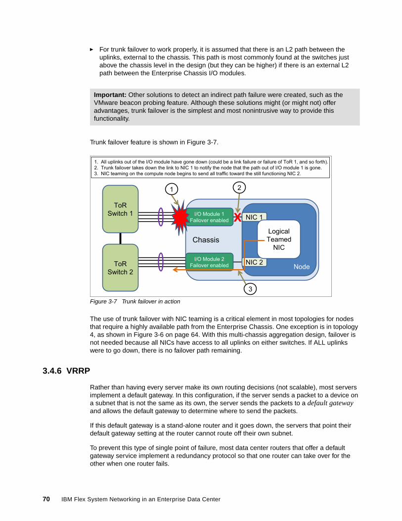
� For trunk failover to work properly, it is assumed that there is an L2 path between the uplinks, external to the chassis. This path is most commonly found at the switches just above the chassis level in the design (but they can be higher) if there is an external L2 path between the Enterprise Chassis I/O modules.
Trunk failover feature is shown in Figure 3-7.
Figure 3-7 Trunk failover in action
The use of trunk failover with NIC teaming is a critical element in most topologies for nodes that require a highly available path from the Enterprise Chassis. One exception is in topology 4, as shown in Figure 3-6 on page 64. With this multi-chassis aggregation design, failover is not needed because all NICs have access to all uplinks on either switches. If ALL uplinks were to go down, there is no failover path remaining.
3.4.6 VRRP
Rather than having every server make its own routing decisions (not scalable), most servers implement a default gateway. In this configuration, if the server sends a packet to a device on a subnet that is not the same as its own, the server sends the packets to a default gateway and allows the default gateway to determine where to send the packets.
If this default gateway is a stand-alone router and it goes down, the servers that point their default gateway setting at the router cannot route off their own subnet.
To prevent this type of single point of failure, most data center routers that offer a default gateway service implement a redundancy protocol so that one router can take over for the other when one router fails.
Important: Other solutions to detect an indirect path failure were created, such as the VMware beacon probing feature. Although these solutions might (or might not) offer advantages, trunk failover is the simplest and most nonintrusive way to provide this functionality.
��� ���������� ��� ����������� ����������� ��� ���� ������������������� ��������� ��� ��!����� �� ���"�#�� �������� ����������� ���������� �$�%���� � ��&����� ����������������� ��� ������� ���������� ��'�� $�%������� ������ ������ ��������� ����������������� ������������������ ��$�%�#�
%�����
$ ��
$�%��
$�%�#� �(�����#
� �(������ ����) ������
*�� ����������
����) �����#*�� ����������
X+ ������������$�%
#
'
�
70 IBM Flex System Networking in an Enterprise Data Center
Although there are nonstandard solutions to this issue, for example, Hot Standby Router Protocol (HSRP), most routers now implement standards-based Virtual Router Redundancy Protocol (VRRP).
In its simplest form, two routers that run VRRP share a common IP address (called the Virtual IP address). One router traditionally acts as master and the other as a backup in the event the master goes down. Information is constantly exchanged between the routers to ensure one can provide the services of the default gateway to the devices that point at its Virtual IP address. Servers that require a default gateway service point the default gateway service at the Virtual IP address, and redundancy is provided by the pair of routers that run VRRP.
The EN2092 1Gb Ethernet Switch, EN4093R 10Gb Scalable Switch, and CN4093 10Gb Converged Scalable Switch offer support for VRRP directly within the Enterprise Chassis, but most common data center designs place this function in the routing devices above the chassis (or even higher). The design depends on how important it to have a common L2 network between nodes in different chassis. If needed, this function can be moved within the Enterprise Chassis as networking requirements dictate.
3.5 FCoE capabilities
One common way to reduce management points and networking elements in an environment is by converging technologies that were traditionally implemented on separate physical infrastructures. As when office phone systems are collapsed from a separate cabling plant and components into a common IP infrastructure, Fibre Channel networks also are experiencing this type of convergence. Also, as with phone systems that have moved to Ethernet, Fibre Channel also is moving to Ethernet.
Fibre Channel over Ethernet (FCoE) removes the need for separate HBAs on the servers and separate Fibre Channel cables out of the back of the server or chassis. Instead, a Converged Network Adapter (CNA) is installed in the server. The CNA presents what appears to be both a NIC and an HBA to the operating system, but the output from the server is only 10 Gb Ethernet.
The IBM Flex System Enterprise Chassis provides multiple I/O modules that support FCoE. The EN4093R 10Gb Scalable Switch, CN4093 10Gb Converged Scalable Switch, and SI4093 System Interconnect Module all support FCoE, with the CN4093 10Gb Converged Scalable Switch also supporting the Fibre Channel Forwarder (FCF) function. This supports NPV, full fabric FC, and native FC ports.
This FCoE function also requires the correct components on the Compute Nodes in the form of the proper CNA and licensing. No special license is needed on any of the I/O modules to support FCoE because support comes as part of the base product.
The EN4091 10Gb Ethernet Pass-thru can also provide support for FCoE, assuming the proper CNA and license are on the Compute Node and the upstream connection supports FCoE traffic.
Important: Although they offer similar services, HSRP and VRRP are not compatible with each other.
Chapter 3. IBM Flex System data center network design basics 71
The EN4093R 10Gb Scalable Switch and SI4093 System Interconnect Module are FIP Snooping Bridges (FSB) and thus provide FCoE transit services between the Compute Node and an upstream Fibre Channel Forwarder (FCF) device. A typical design requires an upstream device such as an IBM G8264CS switch, that breaks the FC portion of the FCoE out to the necessary FC format.
The CN4093 10Gb Converged Scalable Switch also can act as an FSB, but if wanted, can operate as an FCF, which allows the switch to support a full fabric mode for direct storage attachment, or in N Port Virtualizer (NPV) mode, for connection to a non-IBM SAN fabric. The CN4093 10Gb Converged Scalable Switch also supports native FC ports for directly connecting FC devices to the CN4093 10Gb Converged Scalable Switch.
Because the Enterprise Chassis also supports native Fibre Channel modules and various FCoE technologies, it can provide a storage connection solution that meets any wanted goal with regard to remote storage access.
3.6 Virtual Fabric vNIC solution capabilities
Virtual Network Interface Controller (vNIC) is a way to divide a physical NIC into smaller logical NICs (or partition them) so that the OS has more ways to logically connect to the infrastructure. The vNIC feature is supported only on 10 Gb ports that face the compute nodes within the chassis, and only on the certain Ethernet I/O modules. These currently include the EN4093R 10Gb Scalable Switch and CN4093 10Gb Converged Scalable Switch. vNIC also requires a node adapter that also supports this functionality.
As of this writing, there are two primary forms of vNIC available: Virtual Fabric mode (or Switch dependent mode) and Switch independent mode. The Virtual Fabric mode also is subdivided into two submodes: dedicated uplink vNIC mode and shared uplink vNIC mode.
All vNIC modes share the following common elements:
� They are supported only on 10 Gb connections.
� Each vNIC mode allows a NIC to be divided into up to four vNICs per physical NIC (can be less than four, but not more).
� They all require an adapter that has support for one or more of the vNIC modes.
� When vNICs are created, the default bandwidth is 2.5 Gb for each vNIC, but they can be configured to be anywhere from 100 Mb up to the full bandwidth of the NIC.
� The bandwidth of all configured vNICs on a physical NIC cannot exceed 10 Gb.
� All modes support FCoE.
Important: In its default mode, the SI4093 System Interconnect Module supports passing the FCoE traffic up to the FCF, but no FSB support. If FIP snooping is required on the SI4093 System Interconnect Module, it must be placed into local domain SPAR mode.
72 IBM Flex System Networking in an Enterprise Data Center
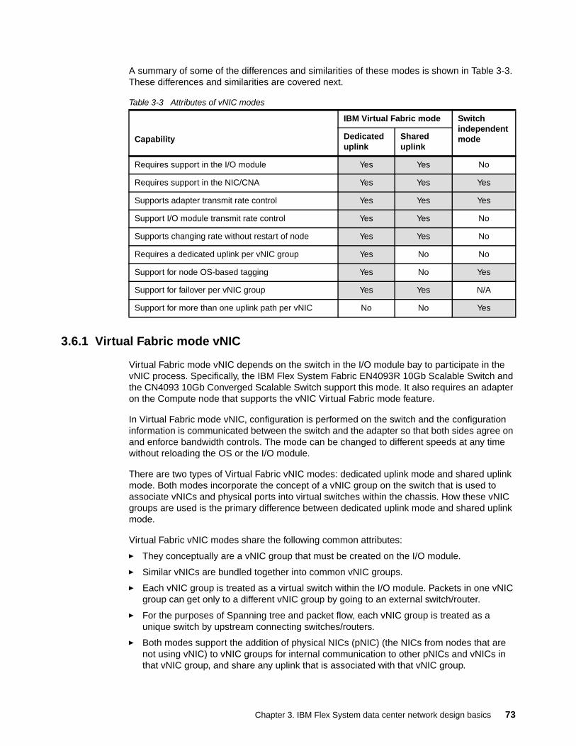
A summary of some of the differences and similarities of these modes is shown in Table 3-3. These differences and similarities are covered next.
Table 3-3 Attributes of vNIC modes
3.6.1 Virtual Fabric mode vNIC
Virtual Fabric mode vNIC depends on the switch in the I/O module bay to participate in the vNIC process. Specifically, the IBM Flex System Fabric EN4093R 10Gb Scalable Switch and the CN4093 10Gb Converged Scalable Switch support this mode. It also requires an adapter on the Compute node that supports the vNIC Virtual Fabric mode feature.
In Virtual Fabric mode vNIC, configuration is performed on the switch and the configuration information is communicated between the switch and the adapter so that both sides agree on and enforce bandwidth controls. The mode can be changed to different speeds at any time without reloading the OS or the I/O module.
There are two types of Virtual Fabric vNIC modes: dedicated uplink mode and shared uplink mode. Both modes incorporate the concept of a vNIC group on the switch that is used to associate vNICs and physical ports into virtual switches within the chassis. How these vNIC groups are used is the primary difference between dedicated uplink mode and shared uplink mode.
Virtual Fabric vNIC modes share the following common attributes:
� They conceptually are a vNIC group that must be created on the I/O module.
� Similar vNICs are bundled together into common vNIC groups.
� Each vNIC group is treated as a virtual switch within the I/O module. Packets in one vNIC group can get only to a different vNIC group by going to an external switch/router.
� For the purposes of Spanning tree and packet flow, each vNIC group is treated as a unique switch by upstream connecting switches/routers.
� Both modes support the addition of physical NICs (pNIC) (the NICs from nodes that are not using vNIC) to vNIC groups for internal communication to other pNICs and vNICs in that vNIC group, and share any uplink that is associated with that vNIC group.
Capability
IBM Virtual Fabric mode Switch independent modeDedicated
uplinkShared uplink
Requires support in the I/O module Yes Yes No
Requires support in the NIC/CNA Yes Yes Yes
Supports adapter transmit rate control Yes Yes Yes
Support I/O module transmit rate control Yes Yes No
Supports changing rate without restart of node Yes Yes No
Requires a dedicated uplink per vNIC group Yes No No
Support for node OS-based tagging Yes No Yes
Support for failover per vNIC group Yes Yes N/A
Support for more than one uplink path per vNIC No No Yes
Chapter 3. IBM Flex System data center network design basics 73
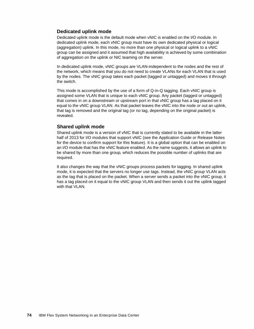
Dedicated uplink modeDedicated uplink mode is the default mode when vNIC is enabled on the I/O module. In dedicated uplink mode, each vNIC group must have its own dedicated physical or logical (aggregation) uplink. In this mode, no more than one physical or logical uplink to a vNIC group can be assigned and it assumed that high availability is achieved by some combination of aggregation on the uplink or NIC teaming on the server.
In dedicated uplink mode, vNIC groups are VLAN-independent to the nodes and the rest of the network, which means that you do not need to create VLANs for each VLAN that is used by the nodes. The vNIC group takes each packet (tagged or untagged) and moves it through the switch.
This mode is accomplished by the use of a form of Q-in-Q tagging. Each vNIC group is assigned some VLAN that is unique to each vNIC group. Any packet (tagged or untagged) that comes in on a downstream or upstream port in that vNIC group has a tag placed on it equal to the vNIC group VLAN. As that packet leaves the vNIC into the node or out an uplink, that tag is removed and the original tag (or no tag, depending on the original packet) is revealed.
Shared uplink modeShared uplink mode is a version of vNIC that is currently slated to be available in the latter half of 2013 for I/O modules that support vNIC (see the Application Guide or Release Notes for the device to confirm support for this feature). It is a global option that can be enabled on an I/O module that has the vNIC feature enabled. As the name suggests, it allows an uplink to be shared by more than one group, which reduces the possible number of uplinks that are required.
It also changes the way that the vNIC groups process packets for tagging. In shared uplink mode, it is expected that the servers no longer use tags. Instead, the vNIC group VLAN acts as the tag that is placed on the packet. When a server sends a packet into the vNIC group, it has a tag placed on it equal to the vNIC group VLAN and then sends it out the uplink tagged with that VLAN.
74 IBM Flex System Networking in an Enterprise Data Center
Virtual Fabric vNIC shared uplink mode is shown in Figure 3-8.
Figure 3-8 IBM Virtual Fabric vNIC shared uplink mode
3.6.2 Switch-independent mode vNIC
Switch-independent mode vNIC is configured only on the node, and the I/O module is unaware of this virtualization. The I/O module acts as a normal switch in all ways (any VLAN that must be carried through the switch must be created on the switch and allowed on the wanted ports). This mode is enabled at the node directly (via F1 setup at boot time or via Emulex OneCommand manager, or possibly via FSM configuration pattern controls), and has similar rules as dedicated vNIC mode regarding how you can divide the vNIC. But any bandwidth settings are limited to how the node sends traffic, not how the I/O module sends traffic back to the node (since the I/O module is unaware of the vNIC virtualization taking place on the Compute Node). Also, the bandwidth settings cannot be changed in real time, because they require a reload for any speed change to take effect.
Switch independent mode requires setting an LPVID value in the Compute Node NIC configuration, and this is a catch-all VLAN for the vNIC to which it is assigned. Any untagged packet from the OS sent to the vNIC is sent to the switch with the tag of the LPVID for that vNIC. Any tagged packet sent from the OS to the vNIC is sent to the switch with the tag set by the OS (the LPVID is ignored). Owing to this interaction, most users set the LPVID to some unused VLAN, and then tag all packets in the OS. One exception to this is for a Compute Node that needs PXE to boot the base OS. In that case, the LPVID for the vNIC that is providing the PXE service must be set for the wanted PXE VLAN.
Operating SystemVMware ESX Physical NIC
EXT-1
vSwitch1
vSwitch2
vSwitch3
vSwitch4
Compute Node
INT-1
EN4093 10 Gb Scalable Switch
EXT-9
EXT-x
vNIC 1.1 Tag VLAN 100
vNIC 1.2 Tag VLAN 200
vNIC 1.3 Tag VLAN 300
vNIC 1.4 Tag VLAN 400
vmnic8
vmnic6
vmnic4
vmnic2
10 Gb NIC
vNIC-Group 1
VLAN100
vNIC-Group 2VLAN200
vNIC-Group 3VLAN300
vNIC-Group 4VLAN400
Chapter 3. IBM Flex System data center network design basics 75
Because all packets that are coming into the switch from an NIC that is configured for switch independent mode vNIC are always tagged (by the OS or by the LPVID setting if the OS is not tagging), all VLANs that are allowed on the port on the switch side should be tagging as well. This means set the PVID/Native VLAN on the switch port to some unused VLAN, or set it to one that is used and enable PVID tagging to ensure the port sends and receives PVID and Native VLAN packets as tagged.
In most OSs, switch independent mode vNIC supports as many VLANs as the OS supports. One exception is with bare metal Windows OS installations, where in switch independent mode, only a limited number of VLANs are supported per vNIC (maximum of 63 VLANs, but less in some cases, depending on version of Windows and what driver is in use). See the documentation for your NIC for details about any limitations for Windows and switch independent mode vNIC.
In this section, we have described the various modes of vNIC. The mode that is best-suited for a user depends on the user’s requirements. Virtual Fabric dedicated uplink mode offers the most control, and shared uplink mode and switch-independent mode offer the most flexibility with uplink connectivity.
3.7 Unified Fabric Port feature
Unified Fabric Port (UFP) is another approach to NIC virtualization. It is similar to vNIC but with enhanced flexibility and should be considered the direction for future development in the virtual NIC area for IBM switching solutions. UFP is supported today on the EN4093R 10Gb Scalable Switch and CN4093 10Gb Converged Scalable Switch.
UFP and vNIC are mutually exclusive in that you cannot enable UFP and vNIC at the same time on the same switch.
If a comparison were to be made between UFP and vNIC, UFP is most closely related to vNIC Virtual Fabric mode in that in both sides, the switch and the NIC/CNA share in controlling bandwidth usage, but there are significant differences. Compared to vNIC, UFP supports the following modes of operation per virtual NIC (vPort):
� Access: The vPort only allows the default VLAN, which is similar to a physical port in access mode.
� Trunk: The vPort permits host side tagging and supports up to 32 customer-defined VLANs on each vPort (4000 total across all vPorts).
� Tunnel: Q-in-Q mode, where the vPort is customer VLAN-independent (this is the closest to vNIC Virtual Fabric dedicated uplink mode). Tunnel mode is the default mode for a vPort.
� FCoE: Dedicates the specific vPort for FCoE traffic.
The following rules and attributes are associated with UFP vPorts:
� They are supported only on 10 Gb internal interfaces.
� UFP allows a NIC to be divided into up to four virtual NICs called vPorts per physical NIC (can be less than 4, but not more).
� Each vPort can be set for a different mode or same mode (with the exception of the FCoE mode, which is limited only a single vPort on a UFP port, and specifically only vPort 2).
� UFP requires the proper support in the Compute Node for any port using UFP.
76 IBM Flex System Networking in an Enterprise Data Center

� By default, each vPort is ensured 2.5 Gb and can burst up to the full 10G if other vPorts do not need the bandwidth. The ensured minimum bandwidth and maximum bandwidth for each vPort are configurable.
� The minimum bandwidth settings of all configured vPorts on a physical NIC cannot exceed 10 Gb.
� Each vPort must have a default VLAN assigned. This default VLAN is used for different purposes in different modes.
� This default VLAN must be unique across the other three vPorts for this physical port, which means that vPort 1.1 must have a different default VLAN assigned than vPort 1.2, 1.3 or 1.4.
� When in trunk or access mode, this default VLAN is untagged by default, but it can be configured for tagging if wanted. This configuration is similar to tagging the native or PVID VLAN on a physical port. In tunnel mode, the default VLAN is the outer tag for the Q-in-Q tunnel through the switch and is not seen by the end hosts and upstream network.
� vPort 2 is the only vPort that supports the FCoE setting. vPort 2 can also be used for other modes (for example, access, trunk or tunnel). However, if you want the physical port to support FCoE, this function can only be defined on vPort 2
Table 3-4 offers some check points in helping to select a UFP mode.
Table 3-4 Attributes of UFP modes
What are some of the criteria to decide if a UFP or vNIC solution should be implemented to provide the virtual NIC capability?
In an environment that has not standardized on any specific virtual NIC technology and does not need per logical NIC failover today, UFP is the way to go. As noted, all future virtual NIC development will be on UFP, and the per-logical NIC failover function will be available in a coming release. UFP has the advantage being able to emulate vNIC virtual fabric modes mode (via tunnel mode for dedicate uplink vNIC and access mode for shared uplink vNIC) but can also offer virtual NIC support with customer VLAN awareness (trunk mode) and shared virtual group uplinks for access and trunk mode vPorts.
If an environment has already standardized on Virtual Fabric mode vNIC and plans to stay with it, or requires the ability of failover per logical group today, Virtual Fabric mode vNIC is recommended.
Capability
IBM UFP vPort mode options
Access Trunk Tunnel FCoE
Support for a single untagged VLAN on the vPorta Yes Yes Yes No
Support for VLAN restrictions on vPortb Yes Yes No Yes
VLAN-independent pass-true for customer VLANs No No Yes No
Support for FCoE on vPort No No No Yes
Support to carry more than 32 VLANs on a vPort No No Yes No
a. Typically a user sets the vPort for access mode if the OS uses this vPort as a simple untagged link. Both trunk and tunnel mode can also support this, but are not necessary to carry only a single untagged VLAN.
b. Access and FCoE mode restricts VLANs to only the default VLAN that is set on the vPort. Trunk mode restricts VLANs to ones that are specifically allowed per VLAN on the switch (up to 32).
Chapter 3. IBM Flex System data center network design basics 77
Note that switch independent mode vNIC is actually exclusive of the above decision making process. Switch independent mode has its own unique attributes, one being truly switch independent, which allows you to configure the switch without restrictions to the virtual NIC technology, other than allowing the proper VLANs. UFP and Virtual Fabric mode vNIC each have a number of unique switch-side requirements and configurations. The down side to Switch independent mode vNIC is the inability to make changes without reloading the server, and the lack of bidirectional bandwidth allocation.
3.8 Easy Connect concept
The Easy Connect concept, some times called Easy Connect mode, is not necessarily a specific feature but a way of using several different existing features to attempt to minimize ongoing switch management requirements. Some customers want the potential uplink cable reduction or increased Compute Node-facing ports that are offered by a switch-based solution, but prefer the ease of use of a pass-through based solution to reduce the potential increase to management required for each edge switch. The Easy Connect concept offers this reduction in management in a fully scalable, switch-based solution.
There are actually several features that can be used to accomplish an Easy Connect solution. A few of those features are described here. Easy Connect takes a switch module and makes it not apparent to the upstream network and the Compute Nodes. It does this by pre-creating a large aggregation of the uplinks so there is no chance for loops, disabling spanning-tree so the upstream does not receive any spanning-tree BPDUs, and then using one form or another of Q-in-Q to mask user VLAN tagging as the packets travel through the switch to remove the need to configure each VLAN the Compute Nodes might need.
After it is configured, a switch in Easy Connect mode does not require any configuration changes as a customer adds and removes VLANs. In essence, Easy Connect turns the switch into a VLAN-independent port aggregator, with support for growing up to the maximum bandwidth of the product (for example, add upgrade FoD’s to increase the 10G links to Compute Nodes and number and types of uplinks available for connection to the upstream network).
To configure an Easy Connect mode, the following options are available:
� For customers that want an Easy Connect type of solution that is immediately ready for use (zero touch switch deployment), the SI4093 System Interconnect Module provides this by default. The SI4093 System Interconnect Module accomplishes this by having the following factory default configuration:
– All default internal and external ports are put into a single SPAR.
– All uplinks are put into a common LACP aggregation and the LACP suspend-port feature is enabled.
– The failover feature is enabled on the common LACP key.
– No spanning-tree support (the SI4093 is designed to never permit more than a single uplink path per SPAR so does not support spanning-tree).
� For customers that want the option of the use of advanced features but also want an Easy Connect mode solution, the EN4093R 10Gb Scalable Switch and CN4093 10Gb Converged Scalable Switch offer configurable options that can make them not apparent to the attaching Compute Nodes and upstream network switches. The option of changing to more advanced modes of configuration when needed also is available.
78 IBM Flex System Networking in an Enterprise Data Center
As noted, the SI4093 System Interconnect Module accomplishes this by defaulting to the SPAR feature in pass-through mode, which puts all Compute Node ports and all uplinks into a common Q-in-Q group. This transparently moves any user packets (tagged or untagged) between the Compute nodes and the upstream networking.
For the EN4093R 10Gb Scalable Switch and CN4093 10Gb Converged Scalable Switch, there are a number of features that can be used to accomplish this need. Some of those features are described here. The primary difference between these switches and the SI4093 System Interconnect Module is that on these models, you must first perform a small set of configuration steps to set up this not apparent mode, after which no more management of the switches is required.
One common element of all Easy Connect modes is the use of a Q-in-Q type operation to hide user VLANs from the switch fabric in the I/O module so that the switch acts as more of a port aggregator and is user VLAN-independent. This Easy Connect mode can be configured by using one of the following features:
� The tagpvid-ingress option� vNIC Virtual Fabric dedicated uplink mode� UFP vPort tunnel mode� SPAR pass-through domain
In general, the features should provide this Easy Connect functionality, with each having some pros and cons. For example, if you want to use Easy Connect with vLAG, you want to use the tagpvid-ingress mode (the other modes do not permit the vLAG ISL). But, if you want to use Easy Connect with FCoE today, you cannot use tagpvid-ingress and must switch to something such as the vNIC Virtual Fabric dedicated uplink mode or UFP tunnel mode (SPAR pass-through mode allows FCoE but does not support FIP snooping, which might not be a concern for some customers).
As an example of how tagpvid-ingress works (and in essence each of these modes), consider the tagpvid-ingress operation. When all internal ports and the wanted uplink ports are placed into a common PVID/Native VLAN and tagpvid-ingress is enabled on these ports (with any wanted aggregation protocol on the uplinks that are required to match the other end of the links), all ports with this Native or PVID setting are part of Q-in-Q tunnel. The Native/PVID VLAN acts as the outer tag (and switches traffic based on this VLAN). The inner customer tag rides through the fabric on the Native or PVID VLAN to the wanted port (or ports) in this tunnel.
In all modes of Easy connect, local switching is still supported. However, if any packet must get to a different subnet or VLAN, it must go to an external L3 routing device to accomplish this task.
It is recommended to contact your local IBM networking resource if you want to implement Easy Connect on the EN4093R 10Gb Scalable Switch and CN4093 10Gb Converged Scalable Switch.
3.9 Stacking feature
Stacking is supported on the EN4093R 10Gb Scalable Switch and CN4093 10Gb Converged Scalable Switch modules. It is provided by reserving a group of uplinks into stacking links and creating a ring of links. This ensures the loss of a single link or single switch in the stack does not lead to a disruption of the stack.
Chapter 3. IBM Flex System data center network design basics 79
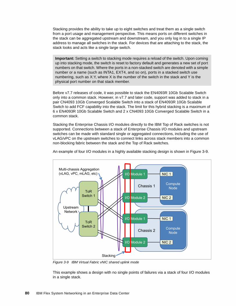
Stacking provides the ability to take up to eight switches and treat them as a single switch from a port usage and management perspective. This means ports on different switches in the stack can be aggregated upstream and downstream, and you only log in to a single IP address to manage all switches in the stack. For devices that are attaching to the stack, the stack looks and acts like a single large switch.
Before v7.7 releases of code, it was possible to stack the EN4093R 10Gb Scalable Switch only into a common stack. However, in v7.7 and later code, support was added to stack in a pair CN4093 10Gb Converged Scalable Switch into a stack of EN4093R 10Gb Scalable Switch to add FCF capability into the stack. The limit for this hybrid stacking is a maximum of 6 x EN4093R 10Gb Scalable Switch and 2 x CN4093 10Gb Converged Scalable Switch in a common stack.
Stacking the Enterprise Chassis I/O modules directly to the IBM Top of Rack switches is not supported. Connections between a stack of Enterprise Chassis I/O modules and upstream switches can be made with standard single or aggregated connections, including the use of vLAG/vPC on the upstream switches to connect links across stack members into a common non-blocking fabric between the stack and the Top of Rack switches.
An example of four I/O modules in a highly available stacking design is shown in Figure 3-9.
Figure 3-9 IBM Virtual Fabric vNIC shared uplink mode
This example shows a design with no single points of failures via a stack of four I/O modules in a single stack.
Important: Setting a switch to stacking mode requires a reload of the switch. Upon coming up into stacking mode, the switch is reset to factory default and generates a new set of port numbers on that switch. Where the ports in a non-stacked switch are denoted with a simple number or a name (such as INTA1, EXT4, and so on), ports in a stacked switch use numbering, such as X:Y, where X is the number of the switch in the stack and Y is the physical port number on that stack member.
Multi-chassis Aggregation
(vLAG, vPC, mLAG, etc)
Chassis 1Compute
Node
NIC 1
NIC 2
Upstream
Network
ToR
Switch 2
ToR
Switch 1
I/O Module 1
I/O Module 2
Stacking
Chassis 2Compute
Node
NIC 1
NIC 2
I/O Module 1
I/O Module 2
80 IBM Flex System Networking in an Enterprise Data Center
One limitation of the current implementation of stacking is that if an upgrade of code is needed, a reload of the entire stack must occur. Because upgrades are uncommon and should be scheduled for non-production hours, a single stack design is efficient and clean. But some customers do not want to have any downtime (scheduled or otherwise) and this single stack design is unwanted. For these users that still want to make the most use of stacking, a two-stack design might be an option. This design features stacking a set of switches in bay 1 into one stack, and a set of switches in bay 2 in a second stack.
The primary advantage to a two-stack design is that each stack can be upgraded one at a time, with the running stack maintaining connectivity for the Compute Nodes during the upgrade and reload. The downside of the two-stack design is that traffic that is flowing from one stack to another stack must go through the upstream network.
As you can see, stacking might be suitable for all customers. However, if it is wanted, it is another tool that is available for building a robust infrastructure by using the Enterprise Chassis I/O modules.
3.10 Openflow support
As of v7.7 code, the EN4093R 10Gb Scalable Switch supports an Openflow option. Openflow is an open standards-based approach for network switching that separates networking into the local data plane (on the switch) and a control plane that is located external to the network switch (usually on a server). Instead of the use of normal learning mechanisms to build up tables of where packets must go, a switch that is running Openflow has the decision-making process in the external server. That server tells the switch to establish “flows” for the sessions that must traverse the switch.
The initial release of support for Openflow on the EN4093R 10Gb Scalable Switch is based on the Openflow 1.0.0 standard and supports the following modes of operation:
� Switch/Hybrid mode: Defaults to all ports as normal switch ports, but can be enabled for Openflow Hybrid mode without a reload, such that some ports can then be enabled for Openflow while others still run normal switching
� Dedicated Openflow mode: Requires a reload to take effect. All ports on the switch are Openflow ports.
By default, the switch is a normal network switch that can be dynamically enabled for Openflow. In this default mode, you can issue a simple operational command to put the switch into Hybrid mode and start to configure ports as Openflow or normal switch ports. Inside the switch, ports that are configured into Openflow mode are isolated from ports in normal mode. Any communication between these Openflow and normal ports must occur outside of the switch.
Hybrid mode Openflow is suitable for users who want to experiment with Openflow on some ports while still use the other ports for regular switch traffic. Dedicated Openflow mode is for a customer that plan to run the entire switch in Openflow mode. It has the benefit of allowing a user to ensure the number of a certain type of flows, known as FDB floes. Hybrid mode does not provide this assurance.
IBM also offers an Openflow controller to manage ports in Openflow mode. For more information about configuring Openflow on the EN4093R 10Gb Scalable Switch, see the appropriate Application Guide for the product.
Chapter 3. IBM Flex System data center network design basics 81
For more information about Openflow, see this website:
http://www.openflow.org
3.11 802.1Qbg Edge Virtual Bridge support
802.1Qbg, also known as Edge Virtual Bridging (EVB) and Virtual Ethernet Port Aggregation (VEPA), is an IEEE standard that is targeted at bringing better network visibility and control into virtualized server environments. It does this by moving the control of packet flows between VMs up from the virtual switch in the hypervisor into the attaching physical switch, which allows the physical switch to provide granular control to the flows between VMs. It also supports the virtualization of the physical NICs into virtual NICs via protocols that are part of the 802.1Qbg specification.
802.1Qbg is supported on the EN4093R 10Gb Scalable Switch and CN4093 10Gb Converged Scalable Switch modules.
The IBM implementation of 802.1Qbg supports the following features:
� Virtual Ethernet Bridging (VEB) and VEPA: Provides support for switching between VMs on a common hypervisor.
� Edge Control Protocol (ECP): Provides reliable delivery of upper layer PDUs.
� Virtual Station Interface (VSI) Discovery and Configuration Protocol (VDP): Support for advertising VSIs to the network and centralized configuration of policies for the VM, regardless of its location in the network.
� EVB Type-Length Value (TLV): A component of LLDP that is used to aid in the discovery and configuration of VEPA, ECP, and VDP.
The current IBM implementation for these products is based on the 802.1Qbg draft, which has some variations from the final standard. For more information about IBM’s implementation and operation of 802.1Qbg, see the appropriate Application Guide for the switch.
For more information about this standard, see this website:
http://standards.ieee.org/about/get/802/802.1.html
3.12 SPAR feature
SPAR is a feature that allows a physical switch to be divided into multiple logical switches. After it is divided, ports within a SPAR session can communicate only with each other. Ports that do not belong to a specific SPAR cannot communicate to ports in that SPAR without going outside the switch.
The EN4093R 10Gb Scalable Switch, the CN4093 10Gb Converged Scalable Switch, and the SI4093 System Interconnect Module support SPAR,
82 IBM Flex System Networking in an Enterprise Data Center
SPAR features the following primary modes of operation:
� Pass-through domain mode
This is the default mode when SPAR is enabled. It is VLAN-independent because it passes tagged and untagged packets through the SPAR session without looking at the customer tag.
On the SI4093 System Interconnect Module, SPAR supports passing FCoE packets to upstream FCF, but without the benefit of FIP snooping within the SPAR. The EN4093R 10Gb Scalable Switch and CN4093 10Gb Converged Scalable Switch do not support FCoE traffic in pass-through domain mode today.
� Local domain mode
This mode is not VLAN-independent and requires a user to create any wanted VLANs on the switch.Currently, there is a limit of 256 VLANs in Local domain mode.
Support is available for FIP Snooping on FCoE sessions. Unlike pass-through domain mode, Local domain mode provides strict control of end host VLAN usage.
Consider the following points regarding SPAR:
� SPAR is disabled by default on the EN4093R 10Gb Scalable Switch and CN4093 10Gb Converged Scalable Switch. SPAR is enabled by default on SI4093 System Interconnect Module, with all ports defaulting to a single pass-through SPAR group. This configuration can be changed if needed.
� Any port can be a member of only a single SPAR group at one time.
� Only a single uplink path is allowed per SPAR group (can be a single link, a static aggregation, or an LACP aggregation). This configuration ensures that no loops are possible with ports in a SPAR group.
� SPAR cannot be used with UFP or Virtual Fabric vNIC. Switch independent mode vNIC is supported with SPAR. UFP support is slated for a future release.
� Up to eight SPAR sessions per switch are supported. This number might be increased in a future release.
As you can see, SPAR should be considered as another tool in the user toolkit for ways to deploy the Enterprise Chassis Ethernet switching solutions in unique ways.
3.13 Management
The Enterprise Chassis is managed as an integrated solution. It also offers the ability to manage each element as an individual product.
From an I/O module perspective, the Ethernet switch modules can be managed through the IBM Flex System Manager™ (FSM), an integrated management appliance for all IBM Flex System solution components.
Chapter 3. IBM Flex System data center network design basics 83
Network Control, a component of FSM, provides advanced network management functions for IBM Flex System Enterprise Chassis network devices. The following functions are included in network control:
� Discovery� Inventory� Network topology� Health and status monitoring� Configuring network devices
Network Control is a preinstalled plug-in that builds on base management software capabilities. This build is done by integrating the launch of vendor-based device management tools, topology views of network connectivity, and subnet-based views of servers and network devices.
Network Control offers the following network-management capabilities:
� Discover network devices in your environment
� Review network device inventory in tables or a network topology view
� Monitor the health and status of network devices
� Manage devices by groups: Ethernet switches, Fibre Channel over Ethernet, or Subnet
� View network device configuration settings and apply templates to configure devices, including Converged Enhanced Ethernet quality of service (QoS), VLANs, and Link Layer Discovery Protocol (LLDP)
� View systems according to VLAN and subnet
� Run network diagnostic tools, such as ping and traceroute
� Create logical network profiles to quickly establish VLAN connectivity
� Simplify VM connections management by configuring multiple characteristics of a network when virtual machines are part of a network system pool
� With management software VMControl, maintain network state (VLANs and ACLs) as a virtual machine is migrated (KVM)
� Manage virtual switches, including virtual Ethernet bridges
� Configure port profiles, a collection of network settings associated with a virtual system
� Automatically configure devices in network systems pools
Ethernet I/O modules also can be managed by the command-line interface (CLI), web interface, IBM System Networking Switch Center, or any third-party SNMP-based management tool.
The EN4093R 10Gb Scalable Switch, CN4093 10Gb Converged Scalable Switch, and the EN2092 1Gb Ethernet Switch modules all offer two CLI options (because it is a non-managed device, the pass-through module has no user interface). The default CLI for these Ethernet switch modules is the IBM Networking OS CLI, which is a menu-driven interface. A user also can enable an optional CLI that is known as industry standard CLI (isCLI) that more closely resembles Cisco IOS CLI. The SI4093 System Interconnect Module only supports the isCLI option for CLI access.
For more information about how to configure various features and the operation of the various user interfaces, see the Application and Command Reference guides, which are available at this website:
http://publib.boulder.ibm.com/infocenter/flexsys/information/index.jsp
84 IBM Flex System Networking in an Enterprise Data Center
3.13.1 Management tools and their capabilities
The various user interfaces that are available for the I/O modules, whether the CLI or the web-based GUI, offer the ability to fully configure and manage all features that are available to the switches. Some elements of the modules can be configured from the CMM user interface.
The best tool for a user often depends on that user’s experience with different interfaces and their knowledge of networking features. Most commonly, the CLI is used by those who work with networks as part of their day-to-day jobs. The CLI offers the quickest way to accomplish tasks, such as scripting an entire configuration. The downside to the CLI is that it tends to be more cryptic to those that do not use them every day. For those users that do not need the power of the CLI, the web-based GUI permits the configuration and management of all switch features.
IBM System Networking Switch CenterAside from the tools that run directly on the modules, IBM also offers IBM SNSC, a tool that provides the following functions:
� Improve network visibility and drive availability, reliability and performance
� Simplify management of large groups of switches with automatic discovery of switches on the network
� Automate and integrate management, deployment and monitoring
� Simple network management protocol (SNMP)- based configuration and management
� Support of network policies for virtualization
� Authentication and authorization
� Fault and performance management
� Integration with IBM Systems Director and VMware Virtual Center and vSphere clients
For more information about IBM SNSC, see this website:
http://www-03.ibm.com/systems/networking/software/snsc/index.html
Any third-party management platforms that support SNMP also can be used to configure and manage the modules.
IBM Fabric ManagerBy using IBM Fabric Manager (IFM), you can quickly replace and recover compute nodes in your environment.
IFM assigns Ethernet MAC, Fibre Channel worldwide name (WWN), and serial-attached SCSI (SAS) WWN addresses so that any compute nodes that are plugged into those bays take on the assigned addresses. These assignments enable the Ethernet and Fibre Channel infrastructure to be configured once and before any compute nodes are connected to the chassis.
With IFM, you can monitor the health of compute nodes and automatically without user intervention replace a failed compute node from a designated pool of spare compute nodes. After receiving a failure alert, IFM attempts to power off the failing compute node, read the IFM virtualized addresses and boot target parameters, apply these parameters to the next compute node in the standby pool, and power on the standby compute node.
Chapter 3. IBM Flex System data center network design basics 85
You can also pre-assign MAC and WWN addresses and storage boot targets for up to 256 chassis or 3584 compute nodes. By using an enhanced GUI, you can create addresses for compute nodes and save the address profiles. You then can deploy the addresses to the bays in the same chassis or in up to 256 different chassis without any compute nodes installed in the chassis. Additionally, you can create profiles for chassis not installed in the environment by associating an IP address to the future chassis.
IFM is available as a Feature on Demand (FoD) through the IBM Flex System Manager management software.
3.14 Summary and conclusions
The IBM Flex System platform provides a unique set of features that enable the integration of leading-edge technologies and transformation approaches into the data centers. These IBM Flex System features ensure that the availability, performance, scalability, security, and manageability goals of the data center networking design are met as efficiently as possible.
The key data center technology implementation trends include the virtualization of servers, storage, and networks. Trends also include the steps toward infrastructure convergence that are based on mature 10 Gb Ethernet technology. In addition, the data center network is being flattened, and the logical overlay network becomes important in overall network design. These approaches and directions are fully supported by IBM Flex System offerings.
The following IBM Flex System data center networking capabilities provide solutions to many issues that arise in data centers where new technologies and approaches are being adopted:
� Network administrator responsibilities can no longer be limited by the NIC level. Administrators must consider the platforms of the server network-specific features and requirements, such as vSwitches. IBM offers Distributed Switch 5000V that provides standard functional capabilities and management interfaces to ensure smooth integration into a data center network management framework.
� After 10 Gb Ethernet networks reach their maturity and price attractiveness, they can provide sufficient bandwidth for virtual machines in virtualized server environments and become a foundation of unified converged infrastructure. IBM Flex System offers 10 Gb Ethernet Scalable Switches and Pass-through modules that can be used to build a unified converged fabric.
� Although 10 Gb Ethernet is becoming a prevalent server network connectivity technology, there is a need to go beyond 10 Gb to avoid oversubscription in switch-to-switch connectivity, thus freeing room for emerging technologies, such as 40 Gb Ethernet. IBM Flex System offers the industry’s first 40 Gb Ethernet-capable switch, EN4093, to ensure that the sufficient bandwidth is available for inter-switch links.
� Network infrastructure must be VM-aware to ensure the end-to-end QoS and security policy enforcement. IBM Flex System network switches offer VMready capability that provides VM visibility to the network and ensures that the network policies are implemented and enforced end-to-end.
� Pay as you grow scalability becomes an essential approach as increasing network bandwidth demands must be satisfied in a cost-efficient way with no disruption in network services. IBM Flex System offers scalable switches that enable ports when required by purchasing and activates simple software FoD upgrades without the need to buy and install additional hardware.
86 IBM Flex System Networking in an Enterprise Data Center

� Infrastructure management integration becomes more important because the interrelations between appliances and functions are difficult to control and manage. Without integrated tools that simplify the data center operations, managing the infrastructure box-by-box becomes cumbersome. IBM Flex System offers centralized systems management with the integrated management appliance (IBM Flex System Manager) that integrates network management functions into a common data center management framework from a single pane of glass.
Chapter 3. IBM Flex System data center network design basics 87

88 IBM Flex System Networking in an Enterprise Data Center
ronyms
ACL access control list
ACLs access control lists
AFT adapter fault tolerance
ALB adaptive load balancing
BE3 BladeEngine 3
BPDUs Bridge Protocol Data Units
CEE Converged Enhanced Ethernet
CLI command line interface
CNA converged network adapter
CNAs converged network adapters
CRM customer relationship management system
DAC direct-attach cable
DACs direct-attach cables
DCB Data Center Bridging
DMA direct memory access
ECP Edge Control Protocol
ETS Enhanced Transmission Selection
EVB Edge Virtual Bridging
FC Fibre Channel
FCF FCoE Forwarder
FCF Fibre Channel Forwarder
FCFs Fibre Channel Forwarders
FCP Fibre Channel protocol
FCoCEE Fibre Channel Over Converged Enhanced Ethernet
FCoE Fibre Channel over Ethernet
FDX Full-duplex
FIP FCoE Initialization Protocol
FLR Function Level Reset
FPMA Fabric Provided MAC Addressing
FSB FIP Snooping Bridges
FSM Flex System Manager
FoD Feature on Demand
HA high availability
HBAs host bus adapters
HSRP Hot Standby Router Protocol
IBM International Business Machines Corporation
IFM IBM Fabric Manager
Abbreviations and ac
© Copyright IBM Corp. 2013. All rights reserved.
ITSO International Technical Support Organization
KVM kernel-based virtual machine
L2 Layer 2
LACP Link Aggregation Control Protocol
LACPDU LACP Data Unit
LAG Link Aggregation Group
LAGs link aggregation groups
LAN local area network
LLDP Link Layer Discovery Protocol
LOM LAN on system board
LSO Large Send Offload
MAC media access control
MSTP Multiple STP
NAS network-attached storage
NICs network interface controllers
NPIV N_Port ID Virtualization
NPV N Port Virtualizer
NTP Network Time Protocol
OSs operating systems
PAgP Port Aggregation Protocol
PDUs protocol data units
PFC Priority-based Flow Control
PIM Protocol Independent Multicast
PVRST Per VLAN Rapid Spanning Tree
PXE Preboot Execution Environment
QoS quality of service
RAS reliability, availability, and serviceability
RMON Remote Monitoring
ROI return on investment
RSCN Registered State Change Notification
RSS Receive Side Scaling
RSTP Rapid Spanning Tree
RoCE RDMA over Converged Ethernet
SAN storage area network
SAS serial-attached SCSI
SFT switch fault tolerance
SLAs service-level agreements
SLP Service Location Protocol
89

SNMP Simple Network Management Protocol
SNSC System Networking Switch Center
SPAN switch port analyzer
SPAR Switch Partitioning
SSH Secure Shell
SoL Serial over LAN
TCO total cost of ownership
TLV Type-Length Value
TOE TCP offload Engine
TSO TCP Segmentation Offload
Tb terabit
ToR top-of-rack
UFP Unified Fabric Port
UFPs unified fabric ports
VEB Virtual Ethernet Bridging
VEPA Virtual Ethernet Port Aggregator
VIOS Virtual I/O Server
VLAN Virtual Land Area Network
VLANs Virtual LANs
VM virtual machine
VMs virtual machines
VPD vital product data
VRRP Virtual Router Redundancy Protocol
VSI Virtual Station Interface
VSS Virtual Switch System
WRR Weighted Round Robin
WWN worldwide name
WoL Wake on LAN
iSCSI Internet Small Computer System Interface
isCLI industry standard CLI
pNIC physical NIC
sFTP Secure FTP
vLAG virtual Link Aggregation
vLAGs Virtual link aggregation groups
vNIC virtual NIC
vNIC2 Virtual NIC 2
vNICs Virtual NICs
vPC virtual Port Channel
90 IBM Flex System Networking in an Enterprise Data Center
Related publications
The publications that are listed in this section are considered particularly suitable for a more detailed discussion of the topics covered in this paper.
IBM Redbooks
The following IBM Redbooks publications provide more information about the topics that are covered in this document. Some publications that are referenced in this list might be available in softcopy only:
� IBM PureFlex System and IBM Flex System Products and Technology, SG24-7984
� IBM Flex System and PureFlex System Network Implementation, SG24-8089
� 10 Gigabit Ethernet Implementation with IBM System Networking Switches, SG24-7960
� Planning for Converged Fabrics: The Next Step in Data Center Evolution, REDP-4620
� IBM Data Center Networking: Planning for Virtualization and Cloud Computing, SG24-7928
You can search for, view, download, or order these documents and other Redbooks, Redpapers, Web Docs, drafts, and other materials at this website:
http://www.ibm.com/redbooks
Help from IBM
IBM Support and downloads:
http://www.ibm.com/support
IBM Global Services:
http://www.ibm.com/services
© Copyright IBM Corp. 2013. All rights reserved. 91

92 IBM Flex System Networking in an Enterprise Data Center

®
REDP-4834-01
INTERNATIONAL TECHNICALSUPPORTORGANIZATION
BUILDING TECHNICAL INFORMATION BASED ON PRACTICAL EXPERIENCE
IBM Redbooks are developed by the IBM International Technical Support Organization. Experts from IBM, Customers and Partners from around the world create timely technical information based on realistic scenarios. Specific recommendations are provided to help you implement IT solutions more effectively in your environment.
For more information:ibm.com/redbooks
Redpaper™
IBM Flex System Networking in an Enterprise Data Center
Describes evolution of enterprise data center networking infrastructure
Describes networking architecture and portfolio
Provides in-depth network planning considerations
Networking in data centers today is undergoing a transition from a discrete traditional model to a more flexible, optimized model or the “smarter” model. Clients are looking to support more workloads with decreasing or flat IT budgets. The network architecture on the recently announced IBM Flex System platform is designed to address the key challenges clients are facing today in their data centers.
IBM Flex System, a new category of computing and the next generation of Smarter Computing, offers intelligent workload deployment and management for maximum business agility. This chassis delivers high-speed performance complete with integrated servers, storage, and networking for multi-chassis management in data center compute environments. Its flexible design can meet the needs of varying workloads with independently scalable IT resource pools for higher usage and lower cost per workload. Although increased security and resiliency protect vital information and promote maximum uptime, the integrated, easy-to-use management system reduces setup time and complexity, which provides a quicker path to ROI.
The purpose of this IBM Redpaper publication is to describe how the data center network design approach is transformed with the introduction of new IBM Flex System platform. This IBM Redpaper publication is intended for anyone who wants to learn more about IBM Flex System networking components and solutions.
Back cover