Embed Size (px)
Citation preview
IBTTA NIOP Phase 2 – Parts 1 and 2 Test Plan
FINAL
Submitted May 4, 2017 Version 1.3
IBTTA NIOP Phase 2 – Parts 1 and 2 Test Plan
Version 1.3 05/4/2017 Page i
Contents 1 Background ........................................................................................................................................... 1 2 Approach ............................................................................................................................................... 1
2.1 Test Environment .......................................................................................................................... 2 2.2 Configuration ................................................................................................................................ 2 2.3 Rounds .......................................................................................................................................... 2 2.4 External Factors ............................................................................................................................ 2
3 Terms and Definitions ........................................................................................................................... 3 3.1 Supplied Tags ................................................................................................................................ 3 3.2 Capture Zone ................................................................................................................................. 3 3.3 Tag Memory .................................................................................................................................. 3 3.4 Test Parameters ............................................................................................................................ 4 3.5 Reader Configuration .................................................................................................................... 6 3.6 Reader Interface ........................................................................................................................... 7 3.7 Application Program ..................................................................................................................... 7 3.8 Speed Tolerance ............................................................................................................................ 7
4 Equipment and System Test Requirements and Plan ........................................................................... 7 4.1 Introduction .................................................................................................................................. 7 4.2 Test Schedule ................................................................................................................................ 8 4.3 Pre-Testing Setup and Assumptions ............................................................................................. 8 4.4 Test Rounds and Features to be Tested ...................................................................................... 10 4.5 Transponders .............................................................................................................................. 17 4.6 Vehicles/Drivers .......................................................................................................................... 20 4.7 Data Capture ............................................................................................................................... 20 4.8 Technology to be Tested ............................................................................................................. 22 4.9 Minimum Performance Requirements ....................................................................................... 22
5 Test Parameters .................................................................................................................................. 24 5.1 General Lab Test Standards ........................................................................................................ 24 5.2 Test Details .................................................................................................................................. 25 5.3 Anomaly Handling ....................................................................................................................... 33 5.4 Test Outcome and Final Report(s) .............................................................................................. 43 5.5 Limitations to Test Plan ............................................................................................................... 44
Attachment A Test Case Sheet (SAMPLE) ............................................................................................. A-1 Attachment B STT Test Procedures ....................................................................................................... B-1 1 Scope .................................................................................................................................................. B-4 2 Reference Documents ........................................................................................................................ B-4 3 Background ........................................................................................................................................ B-4 4 Disclaimer ........................................................................................................................................... B-4 5 Site Overview ..................................................................................................................................... B-4
5.1 Test Track ................................................................................................................................... B-4 5.2 Tolling Equipment Layout .......................................................................................................... B-4 5.3 Site Safety and Security ............................................................................................................. B-5 5.4 Personnel Safety ........................................................................................................................ B-5
IBTTA NIOP Phase 2 – Parts 1 and 2 Test Plan
Version 1.3 05/4/2017 Page ii
6 Personnel ........................................................................................................................................... B-5 6.1 Test Engineer ............................................................................................................................. B-5 6.2 Track Inspection ......................................................................................................................... B-5 6.3 Test Vehicle Inspection .............................................................................................................. B-5 6.4 Test Results Validation ............................................................................................................... B-5 6.5 Supporting Personnel ................................................................................................................. B-6 6.6 RFID Tags .................................................................................................................................... B-6 6.7 RFID Reader ................................................................................................................................ B-6 6.8 RFID Cable .................................................................................................................................. B-6
7 Definitions .......................................................................................................................................... B-7 8 Optimized STT Plan ............................................................................................................................ B-8
8.1 Representative Lap .................................................................................................................... B-8 8.2 Test Round 1 – Setup ................................................................................................................. B-9 8.3 Test Round 2 – Setup ................................................................................................................. B-9 8.4 Test Round 3 – Setup ............................................................................................................... B-10 8.5 Test Round 5 – Setup ............................................................................................................... B-10
9 MET STT Application ........................................................................................................................ B-11 9.1 Functions Summary ................................................................................................................. B-11 9.2 Considerations ......................................................................................................................... B-13
Attachment C STT Field Test Procedures .............................................................................................. C-1 1 Scope .................................................................................................................................................. C-4 2 Site Safety and Security ..................................................................................................................... C-4 3 Supporting Personnel ......................................................................................................................... C-4
3.1 Test Director............................................................................................................................... C-4 3.2 Test Lead .................................................................................................................................... C-4 3.3 Vehicle Marshall ......................................................................................................................... C-4 3.4 Test Engineer ............................................................................................................................. C-4 3.5 Drivers ........................................................................................................................................ C-5
4 Equipment (field testing info) ............................................................................................................ C-5 4.1 RFID Antennas ............................................................................................................................ C-5 4.2 RFID Tags .................................................................................................................................... C-5 4.3 RFID Reader ................................................................................................................................ C-5 4.4 RFID Cable .................................................................................................................................. C-5 4.5 Vehicles ...................................................................................................................................... C-6 4.6 Other Infrastructure ................................................................................................................... C-6
5 Pre-test Preparation........................................................................................................................... C-6 5.1 Track Closure .............................................................................................................................. C-6 5.2 Track Inspection ......................................................................................................................... C-6 5.3 Vehicle Inspection ...................................................................................................................... C-6 5.4 Driver Training............................................................................................................................ C-6 5.5 Communication .......................................................................................................................... C-6
6 Preparing Vehicles and Tags .............................................................................................................. C-7 7 Suggested Schedule ........................................................................................................................... C-7 8 Daily Test Preparation ........................................................................................................................ C-8 9 Round 4 Test Procedures ................................................................................................................... C-8
IBTTA NIOP Phase 2 – Parts 1 and 2 Test Plan
Version 1.3 05/4/2017 Page iii
9.1 Single Lane Runs ........................................................................................................................ C-8 9.2 Triple Lane Runs ......................................................................................................................... C-9
10 Data Validation................................................................................................................................... C-9 10.1 Collection of Data ....................................................................................................................... C-9
11 Error Handling .................................................................................................................................... C-9 Attachment D NIOP Test Program Protocol Hypothesis Testing .......................................................... D-1 Attachment E Driver Test Sheet ............................................................................................................ E-1 Attachment F Vehicle Test Sheet .......................................................................................................... F-1 Attachment G Vehicle Inspection Checklist .......................................................................................... G-1 Attachment H Track Inspection Checklist ............................................................................................. H-1
IBTTA NIOP Phase 2 – Parts 1 and 2 Test Plan
Version 1.3 05/4/2017 Page iv
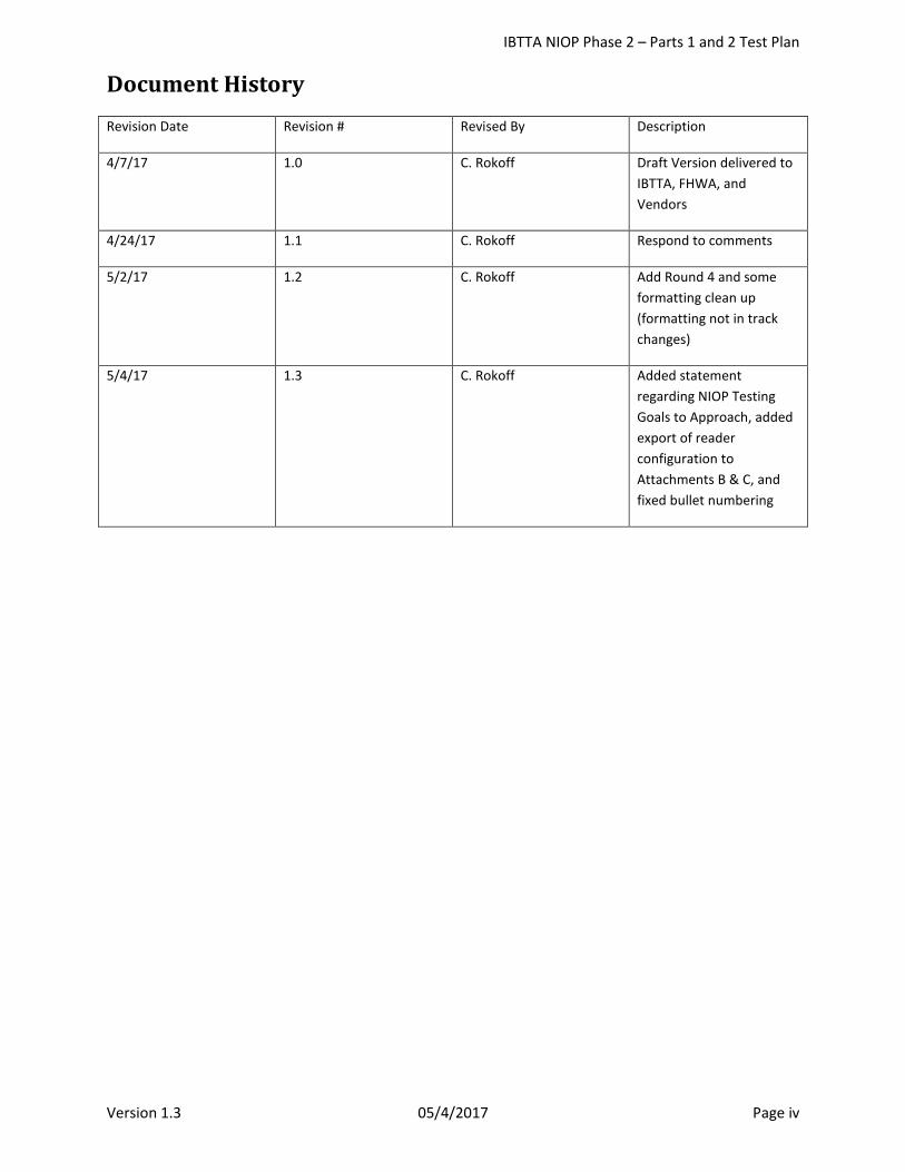
Document History Revision Date Revision # Revised By Description
4/7/17 1.0 C. Rokoff Draft Version delivered to IBTTA, FHWA, and Vendors
4/24/17 1.1 C. Rokoff Respond to comments
5/2/17 1.2 C. Rokoff Add Round 4 and some formatting clean up (formatting not in track changes)
5/4/17 1.3 C. Rokoff Added statement regarding NIOP Testing Goals to Approach, added export of reader configuration to Attachments B & C, and fixed bullet numbering
IBTTA NIOP Phase 2 – Parts 1 and 2 Test Plan
Version 1.3 05/4/2017 Page 1
1 Background The International Bridge, Tunnel and Turnpike Association (IBTTA) was founded in 1932 and is a worldwide association representing toll facility owners and operators and the businesses they serve. IBTTA has members in more than 20 countries and on six continents. Through advocacy, thought leadership and education, members are implementing state-of-the-art, innovative user-based transportation financing solutions to address the critical infrastructure challenges of the 21st century. IBTTA is headquartered in Washington, D.C.
The IBTTA has volunteered, in partnership with the FHWA, to undertake the mission of establishing a national interoperable protocol (NIOP) so that toll paying customers may travel anywhere in North America with a single toll transponder. IBTTA recognizes that many hardware components, software modules, and operational processes are involved in implementing an Electronic Toll Collection (ETC) system program. The technical focus of this initiative, however, deals specifically with the system components that provide the ability to automatically, accurately, and in real-time, communicate and transmit a unique identifier and other data stored from an On-Board Unit (OBU), or transponder, traveling with a vehicle passing through a toll lane/zone, to readers installed at the roadside.
The Roadside Operations Sub-Committee (ROSC) – a technical working group of the IBTTA – has reviewed commonly used protocols and developed a short-list of NIOP candidates that appear to be capable of meeting the technical aspects of the IBTTA North American Toll Interoperability Program Electronic Toll Collection Protocol Requirements Document (Final NIOP Requirements Document). To develop the short-list, the committee evaluated protocols against NIOP requirements and provided consideration to candidate protocols that were in common use by IBTTA member Agencies. The short-listed protocols were accepted by the IBTTA NIOP Steering Committee in July 2014. The short-listed protocols, hereafter referred to as “Candidate Protocols” are the following:
• ISO 18000 6C (also known as ISO 18000 63, or just 6C) • TDM (also known as IAG or E-ZPass) • SeGo (also known as ISO 18000 6B+)
The IBTTA recruited three volunteer technology providers (the Vendors), 3M, Kapsch and TransCore who have committed to sponsor their respective protocols 6C, TDM and SeGo; and support this testing by supplying equipment and expertise to assist the IBTTA in carrying out the testing. The reader vendors will tune their equipment during set-up for each round of testing.
IBTTA selected the OmniAir (formerly OmniAir Certification Services) team for technical services to assist in the conduct and analysis of testing the candidate NIOP protocols. The tolling protocol technology selected out of this process will facilitate seamless travel by roadway users of tolling facilities using a single on-board device across North America. During Phase 1 of the NIOP testing, each of the “Candidate Protocols” was verified for Conformance to their protocols.
This Phase 2 – Parts 1 and 2 Test Plan provides the necessary information to develop and oversee a lab/field performance testing program for compliant NIOP candidate protocols that supports the IBTTA’s evaluation and selection process. As required by the FHWA approved plan, a separate NIOP Phase 2 – Part 3 Test Plan will be developed for the field testing program for Round 6 (if required).
2 Approach The IBTTA has stipulated over 100 requirements for the NIOP protocol. These represent thousands of combinations which, as a practical matter, cannot all be tested. The IBTTA has therefore settled on testing what they have determined to be the most important requirements. These are:
• Handshake degradation of one protocol due to another protocol
IBTTA NIOP Phase 2 – Parts 1 and 2 Test Plan
Version 1.3 05/4/2017 Page 2
• Tag Read accuracy • Tag Write accuracy
The goal of these tests is to clearly define and measure these parameters to ensure consistent testing among all protocols and vendors.
OmniAir developed the Test Approach document in collaboration with IBTTA Roadside Operations Subcommittee, and testing subgroup members to outline testing strategies that will be used to accomplish the NIOP Testing Goals that were established by the IBTTA. Using the approved Test Approach document as the guide, we believe the supporting Test Plan document submitted to the IBTTA for approval conforms to the Test Approach.
2.1 Test Environment Testing will take place in a Lab and in the “Field”. Lab testing will utilize test vehicles (approximately 1 foot long) specifically designed to carry tags, at 15 to 100 mph, down a single indoor track through a tag capture zone. Each test vehicle will carry a single tag of the selected protocol during the test. The height from the lab floor to the transponder in the STT vehicle is 2.6 feet. Field testing will utilize actual vehicles on a three lane outside test facility. The field test will employ lanes of 12 ft. width and the mounting pipe for the antenna(s) will be 17 ft. 6-inch height from the roadway. Vendors will provide and position the lab and field antenna or antennas to their requirements while maintaining the prescribed capture zone. See Section 4.3 for more details on assumptions for Vendor setup.
2.2 Configuration Each protocol has a well-defined set of technical specifications and operational parameters for reading from and writing to tags and it is up to the reader manufacturers and tag suppliers to follow these specifications and provide the tools that implement the operational parameters. Conformance to the specifications was validated during Phase 1 of the NIOP Testing. However, it is up to the protocol sponsors (i.e. Vendors) to configure those tools and establish the physical installation to optimize the system. These configurations can be very different and produce diverse results (e.g. handshakes, tag selection) for the same installation. For this reason, it is important that the configuration and mode of operation of the reader is consistent across different test scenarios and disclosed to ensure certification of the results.
2.3 Rounds Testing is defined in a series of six “Rounds” designed to methodically determine handshake and accuracy parameters supported by statistically significant confidence levels. Following is a summary of the Rounds, where they are performed, and the parameter they are testing.
Table 1 – Summary of Test Rounds Round Handshake/Accuracy Lab/Field Pass/Fail
1 Handshake Lab No 2 Handshake Lab Yes 3 Handshake Lab No 4 Handshake Field No 5 Accuracy Lab Yes
6 (TBD) Accuracy Field Yes
2.4 External Factors There a multitude of external real world factors that can affect the parameters being tested. These range from driver behavior to RF interference. Nearly all of these are random in nature and as such cannot be duplicated in a
IBTTA NIOP Phase 2 – Parts 1 and 2 Test Plan
Version 1.3 05/4/2017 Page 3
controlled test environment. Rather than selecting and introducing pseudo-random parameters, the test will exclude these factors as much as possible to derive a baseline conclusion.
3 Terms and Definitions The items of this section apply to both lab and field testing.
3.1 Supplied Tags Tags used for testing will be encoded per current specifications and supplied with the encoded Agency and Tag Serial Number printed on the tag. SeGo and 6C tags will be “sticker tags” and TDM tags will be hard case with a battery. All tags will be single protocol of the type to be mounted on the interior windshield of a car. The Tag Serial Number must be unique for each tag of a given protocol and the Agency and/or Group code should not correspond to any current or future toll facility. Required quantity of tags is:
• TDM – 50 (Group ID will be 1) • 6C - 50 • SeGo - 50
3.2 Capture Zone The “Capture Zone” shall be defined as the length (in feet) measured along the road (or track) in the direction of travel, beginning at the point where a tag starts to read and ending at the point when the tag stops reading. The capture zone shall not exceed 18 feet for any of the protocols. The capture zone, as defined, is not a function of vehicle speed and is determined by moving a properly mounted tag past the antenna in 1 foot increments and recording the points when the tag starts and stops reading. When measuring the capture zone, the readers must be set to single lane, single protocol mode when determining the capture zone for that protocol. The reader would be cycled through each of the three protocols in turn to verify capture zone size for each protocol. The field capture zone shall be determined by each vendor but must be consistent for all rounds for that vendor’s reader. The lab testing will use the same length cable, antenna angle, and reader configurations and the OmniAir team will make any lab modifications necessary to replicate the field capture zones. Alternatively, the vendor can establish their capture zone in the lab, and then it will be the vendor’s responsibility to make the capture zones in the field replicate the lab established capture zones.
Vehicles chosen for field testing will be sedans with tag mounting locations of 4.5 ft. +/- 1 ft. from the ground and windshield angles of 24 degrees +/- 2 degree range to correlate with the lab test vehicles which have a fixed windshield angle of 24 degrees.
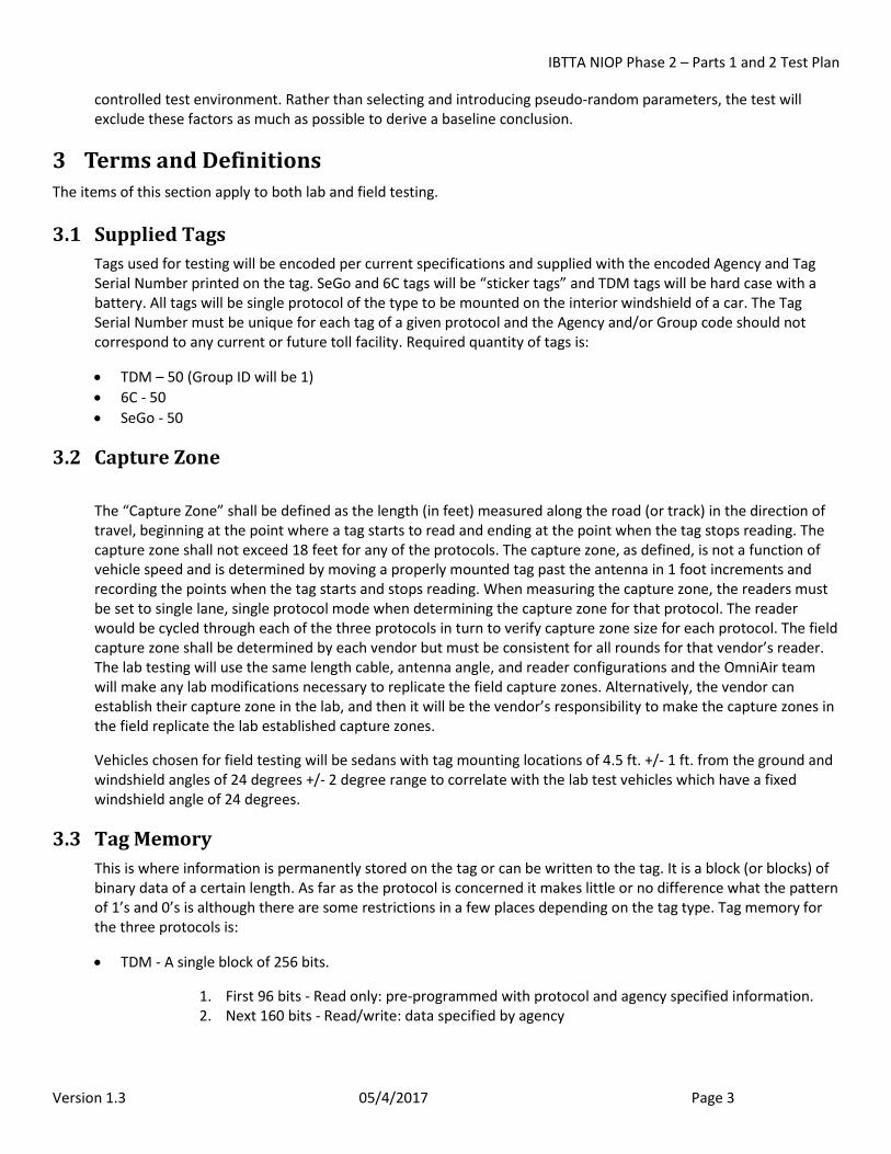
3.3 Tag Memory This is where information is permanently stored on the tag or can be written to the tag. It is a block (or blocks) of binary data of a certain length. As far as the protocol is concerned it makes little or no difference what the pattern of 1’s and 0’s is although there are some restrictions in a few places depending on the tag type. Tag memory for the three protocols is:
• TDM - A single block of 256 bits.
1. First 96 bits - Read only: pre-programmed with protocol and agency specified information. 2. Next 160 bits - Read/write: data specified by agency
IBTTA NIOP Phase 2 – Parts 1 and 2 Test Plan
Version 1.3 05/4/2017 Page 4
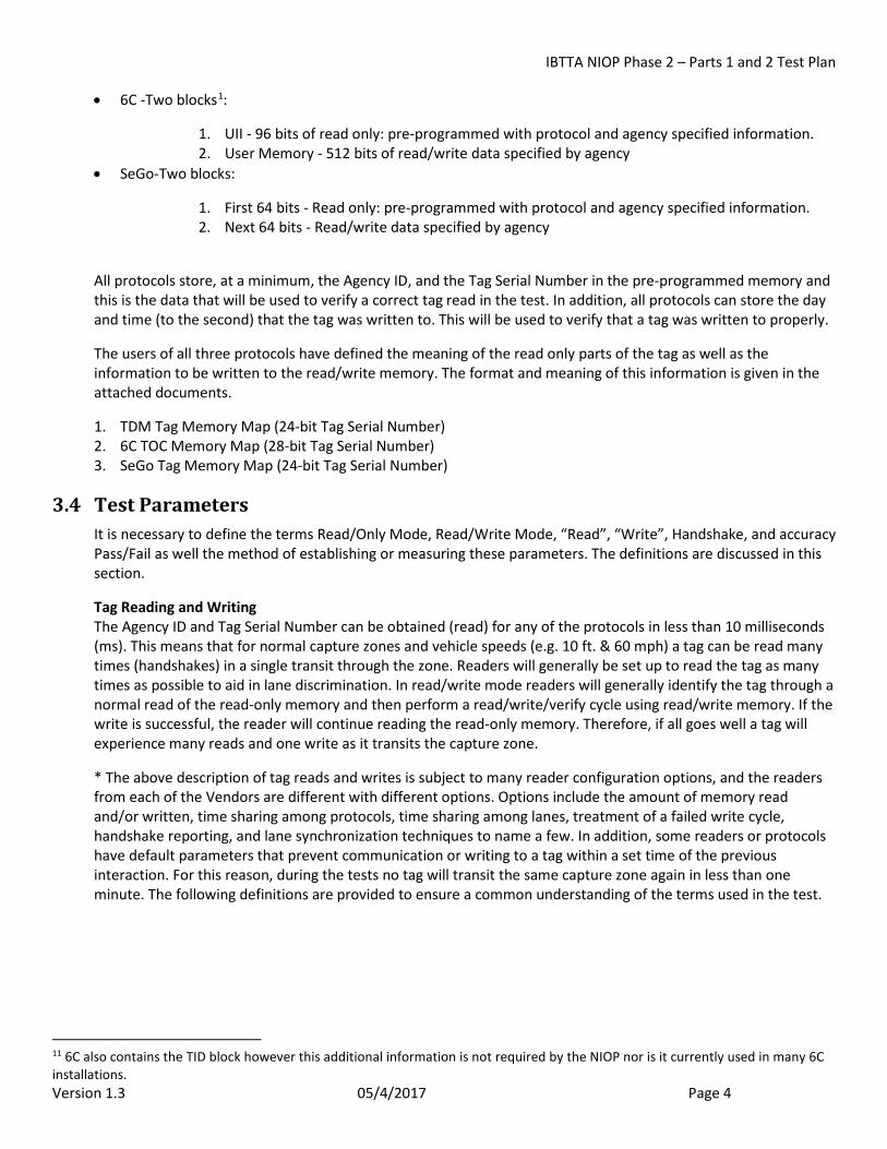
• 6C -Two blocks1:
1. UII - 96 bits of read only: pre-programmed with protocol and agency specified information. 2. User Memory - 512 bits of read/write data specified by agency
• SeGo-Two blocks:
1. First 64 bits - Read only: pre-programmed with protocol and agency specified information. 2. Next 64 bits - Read/write data specified by agency
All protocols store, at a minimum, the Agency ID, and the Tag Serial Number in the pre-programmed memory and this is the data that will be used to verify a correct tag read in the test. In addition, all protocols can store the day and time (to the second) that the tag was written to. This will be used to verify that a tag was written to properly.
The users of all three protocols have defined the meaning of the read only parts of the tag as well as the information to be written to the read/write memory. The format and meaning of this information is given in the attached documents.
1. TDM Tag Memory Map (24-bit Tag Serial Number) 2. 6C TOC Memory Map (28-bit Tag Serial Number) 3. SeGo Tag Memory Map (24-bit Tag Serial Number)
3.4 Test Parameters It is necessary to define the terms Read/Only Mode, Read/Write Mode, “Read”, “Write”, Handshake, and accuracy Pass/Fail as well the method of establishing or measuring these parameters. The definitions are discussed in this section.
Tag Reading and Writing The Agency ID and Tag Serial Number can be obtained (read) for any of the protocols in less than 10 milliseconds (ms). This means that for normal capture zones and vehicle speeds (e.g. 10 ft. & 60 mph) a tag can be read many times (handshakes) in a single transit through the zone. Readers will generally be set up to read the tag as many times as possible to aid in lane discrimination. In read/write mode readers will generally identify the tag through a normal read of the read-only memory and then perform a read/write/verify cycle using read/write memory. If the write is successful, the reader will continue reading the read-only memory. Therefore, if all goes well a tag will experience many reads and one write as it transits the capture zone.
* The above description of tag reads and writes is subject to many reader configuration options, and the readers from each of the Vendors are different with different options. Options include the amount of memory read and/or written, time sharing among protocols, time sharing among lanes, treatment of a failed write cycle, handshake reporting, and lane synchronization techniques to name a few. In addition, some readers or protocols have default parameters that prevent communication or writing to a tag within a set time of the previous interaction. For this reason, during the tests no tag will transit the same capture zone again in less than one minute. The following definitions are provided to ensure a common understanding of the terms used in the test.
11 6C also contains the TID block however this additional information is not required by the NIOP nor is it currently used in many 6C installations.
IBTTA NIOP Phase 2 – Parts 1 and 2 Test Plan
Version 1.3 05/4/2017 Page 5
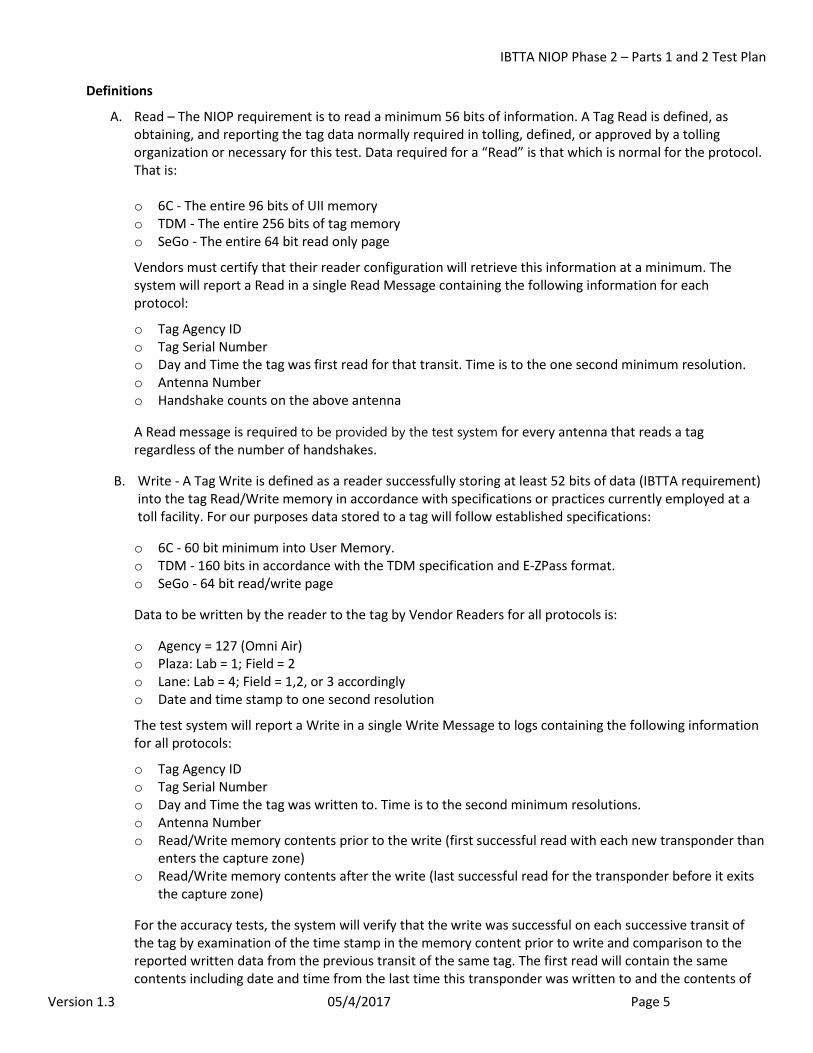
Definitions
A. Read – The NIOP requirement is to read a minimum 56 bits of information. A Tag Read is defined, as obtaining, and reporting the tag data normally required in tolling, defined, or approved by a tolling organization or necessary for this test. Data required for a “Read” is that which is normal for the protocol. That is: o 6C - The entire 96 bits of UII memory o TDM - The entire 256 bits of tag memory o SeGo - The entire 64 bit read only page
Vendors must certify that their reader configuration will retrieve this information at a minimum. The system will report a Read in a single Read Message containing the following information for each protocol:
o Tag Agency ID o Tag Serial Number o Day and Time the tag was first read for that transit. Time is to the one second minimum resolution. o Antenna Number o Handshake counts on the above antenna
A Read message is required to be provided by the test system for every antenna that reads a tag regardless of the number of handshakes.
B. Write - A Tag Write is defined as a reader successfully storing at least 52 bits of data (IBTTA requirement) into the tag Read/Write memory in accordance with specifications or practices currently employed at a toll facility. For our purposes data stored to a tag will follow established specifications:
o 6C - 60 bit minimum into User Memory. o TDM - 160 bits in accordance with the TDM specification and E-ZPass format. o SeGo - 64 bit read/write page
Data to be written by the reader to the tag by Vendor Readers for all protocols is:
o Agency = 127 (Omni Air) o Plaza: Lab = 1; Field = 2 o Lane: Lab = 4; Field = 1,2, or 3 accordingly o Date and time stamp to one second resolution
The test system will report a Write in a single Write Message to logs containing the following information for all protocols:
o Tag Agency ID o Tag Serial Number o Day and Time the tag was written to. Time is to the second minimum resolutions. o Antenna Number o Read/Write memory contents prior to the write (first successful read with each new transponder than
enters the capture zone) o Read/Write memory contents after the write (last successful read for the transponder before it exits
the capture zone)
For the accuracy tests, the system will verify that the write was successful on each successive transit of the tag by examination of the time stamp in the memory content prior to write and comparison to the reported written data from the previous transit of the same tag. The first read will contain the same contents including date and time from the last time this transponder was written to and the contents of

IBTTA NIOP Phase 2 – Parts 1 and 2 Test Plan
Version 1.3 05/4/2017 Page 6
the user memory will be compared to the last read for this same transponder. This will require one additional pass of the tag at the end of each accuracy test. For the Handshake tests, write accuracy is not critical and the write mode will be verified by the system using the time stamp from successive Write messages.
C. Handshake - A correct transmission of the tag’s read-only memory from the tag to the reader. The transmission must involve the complete cycle of interrogation and tag response. A “handshake” is synonymous with a “Read”.
D. Transaction -A transaction is the transit of a transponder into the capture zone and the transaction includes all the “handshakes” for that transit.
E. Transponder – the terms transponder, tag and OBU are used interchangeably throughout this document.
F. Read/Only Mode - A mode of operation wherein a protocol performs one or more Reads as the tag transits the capture zone.
G. Read/Write Mode - A mode of operation wherein a protocol performs one or more Tag Reads and one Tag Write as a tag transits the toll zone. For purposes of this test, each successive Tag Write must contain the date and time to the second.
H. Accuracy - A “Read OK” will be logged for a tag each time it transits a capture zone and results in a successful Read Message when in read only mode or a successful Read Message or Write Message when in read/write mode. Failure to generate either of these messages will result in logging a “No Read” for that transit. A ”Write OK” will be logged for a tag each time it transits a capture zone and results in a successful Write message when in Read/Write mode. Failure to generate this message will result in logging a “No Write” for that transit. The total count of Read OK and Write OK will be used to determine the PASS or FAIL of the accuracy test.
3.5 Reader Configuration Vendors must install the antennas and readers and configure the readers for the tests. There are two factors that are important to these tests; Protocol Modes and Lane Modes. The "Candidate Protocol Reader" is the reader supplied by the sponsoring vendor promoting their Candidate Protocol for the purpose of evaluation of that protocol. The “Local Protocol” for each multi-protocol reader will be the Read Only Protocol being tested alongside the Candidate Protocol in each set of trials. These are listed below for each Vendor.
Table 2 - Protocol Modes Kapsch 3M TransCore
TDM Read/Write (Candidate)
Read Only (Local)
Read Only (Local)
6C Read Only (Local)
Read/Write (Candidate)
Read Only (Local)
SeGo Read Only (Local)
Read Only (Local)
Read/Write (Candidate)
Table 3 - Lane Modes Kapsch 3M TransCore
Single 6C TDM TDM Single SeGo SeGo 6C Single and Triple TDM/6C 6C/TDM SeGo/TDM Single and Triple TDM/SeGo 6C/SeGo SeGo/6C
IBTTA NIOP Phase 2 – Parts 1 and 2 Test Plan
Version 1.3 05/4/2017 Page 7
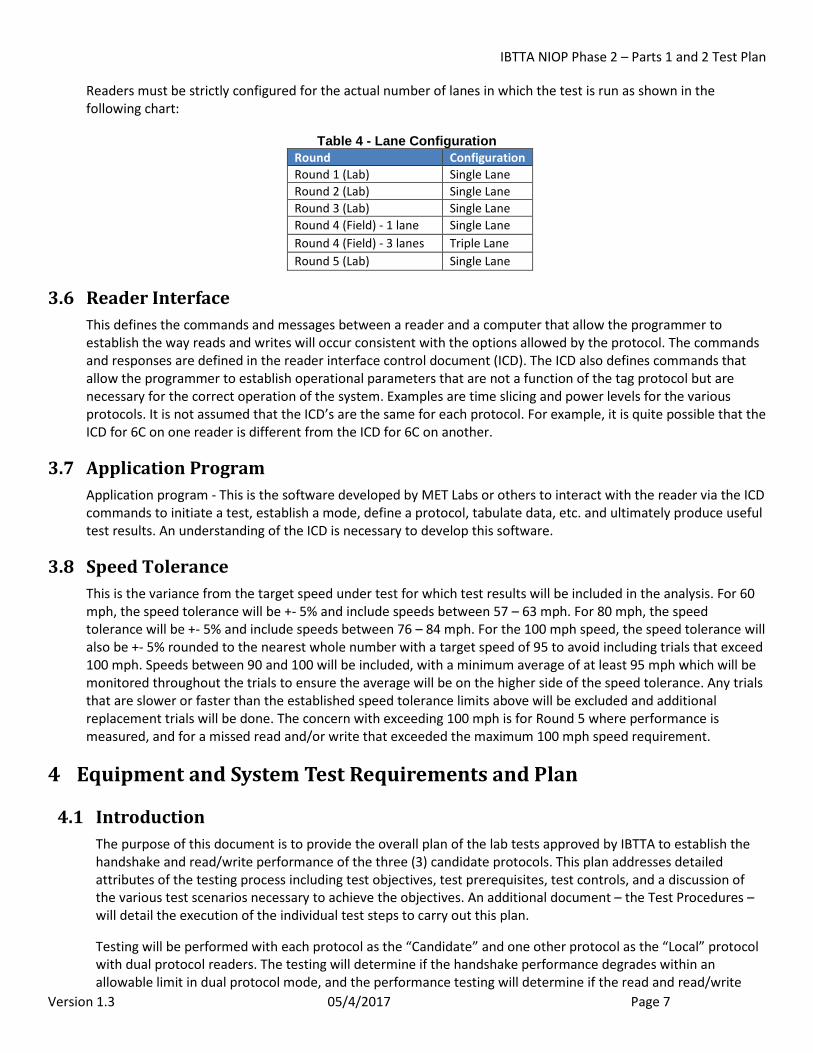
Readers must be strictly configured for the actual number of lanes in which the test is run as shown in the following chart:
Table 4 - Lane Configuration Round Configuration Round 1 (Lab) Single Lane Round 2 (Lab) Single Lane Round 3 (Lab) Single Lane Round 4 (Field) - 1 lane Single Lane Round 4 (Field) - 3 lanes Triple Lane Round 5 (Lab) Single Lane
3.6 Reader Interface This defines the commands and messages between a reader and a computer that allow the programmer to establish the way reads and writes will occur consistent with the options allowed by the protocol. The commands and responses are defined in the reader interface control document (ICD). The ICD also defines commands that allow the programmer to establish operational parameters that are not a function of the tag protocol but are necessary for the correct operation of the system. Examples are time slicing and power levels for the various protocols. It is not assumed that the ICD’s are the same for each protocol. For example, it is quite possible that the ICD for 6C on one reader is different from the ICD for 6C on another.
3.7 Application Program Application program - This is the software developed by MET Labs or others to interact with the reader via the ICD commands to initiate a test, establish a mode, define a protocol, tabulate data, etc. and ultimately produce useful test results. An understanding of the ICD is necessary to develop this software.
3.8 Speed Tolerance This is the variance from the target speed under test for which test results will be included in the analysis. For 60 mph, the speed tolerance will be +- 5% and include speeds between 57 – 63 mph. For 80 mph, the speed tolerance will be +- 5% and include speeds between 76 – 84 mph. For the 100 mph speed, the speed tolerance will also be +- 5% rounded to the nearest whole number with a target speed of 95 to avoid including trials that exceed 100 mph. Speeds between 90 and 100 will be included, with a minimum average of at least 95 mph which will be monitored throughout the trials to ensure the average will be on the higher side of the speed tolerance. Any trials that are slower or faster than the established speed tolerance limits above will be excluded and additional replacement trials will be done. The concern with exceeding 100 mph is for Round 5 where performance is measured, and for a missed read and/or write that exceeded the maximum 100 mph speed requirement.
4 Equipment and System Test Requirements and Plan
4.1 Introduction The purpose of this document is to provide the overall plan of the lab tests approved by IBTTA to establish the handshake and read/write performance of the three (3) candidate protocols. This plan addresses detailed attributes of the testing process including test objectives, test prerequisites, test controls, and a discussion of the various test scenarios necessary to achieve the objectives. An additional document – the Test Procedures – will detail the execution of the individual test steps to carry out this plan.
Testing will be performed with each protocol as the “Candidate” and one other protocol as the “Local” protocol with dual protocol readers. The testing will determine if the handshake performance degrades within an allowable limit in dual protocol mode, and the performance testing will determine if the read and read/write
IBTTA NIOP Phase 2 – Parts 1 and 2 Test Plan
Version 1.3 05/4/2017 Page 8
accuracy are within the IBTTA specified performance standards. The performance requirements from the IBTTA Final Requirements Document, Section 3.7 are shown in Section 4.9 of this Test Plan for each reader and tag protocol combination under test.
Throughout the duration of the testing and reporting, it is not the intent of this testing to compare one vendor’s technology/equipment to other vendor’s systems/results.
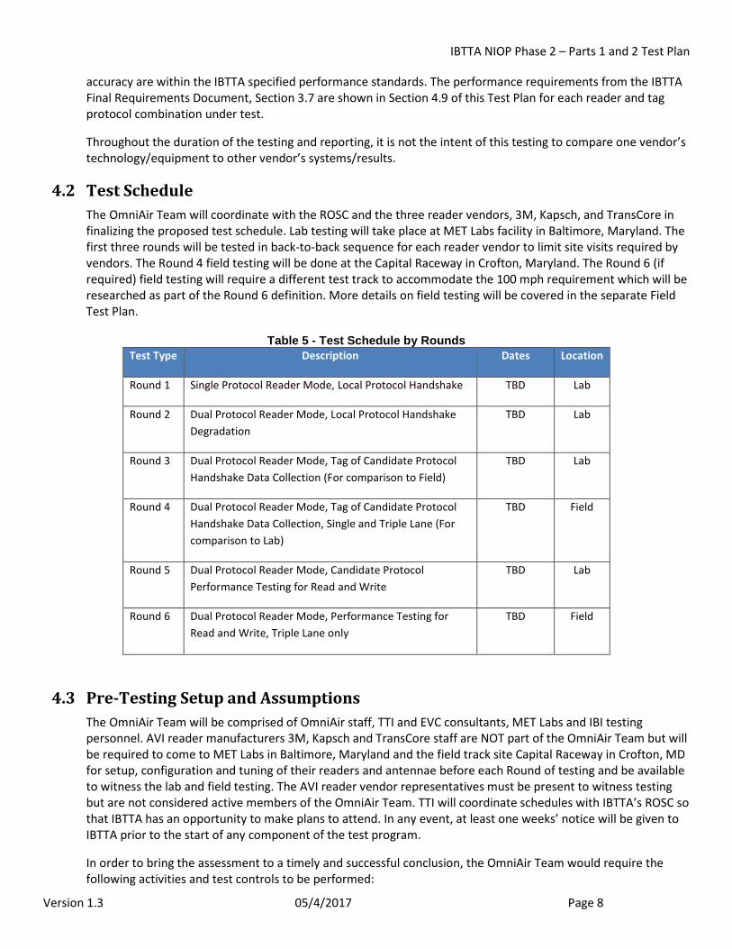
4.2 Test Schedule The OmniAir Team will coordinate with the ROSC and the three reader vendors, 3M, Kapsch, and TransCore in finalizing the proposed test schedule. Lab testing will take place at MET Labs facility in Baltimore, Maryland. The first three rounds will be tested in back-to-back sequence for each reader vendor to limit site visits required by vendors. The Round 4 field testing will be done at the Capital Raceway in Crofton, Maryland. The Round 6 (if required) field testing will require a different test track to accommodate the 100 mph requirement which will be researched as part of the Round 6 definition. More details on field testing will be covered in the separate Field Test Plan.
Table 5 - Test Schedule by Rounds Test Type Description Dates Location
Round 1 Single Protocol Reader Mode, Local Protocol Handshake TBD Lab
Round 2 Dual Protocol Reader Mode, Local Protocol Handshake Degradation
TBD Lab
Round 3 Dual Protocol Reader Mode, Tag of Candidate Protocol Handshake Data Collection (For comparison to Field)
TBD Lab
Round 4 Dual Protocol Reader Mode, Tag of Candidate Protocol Handshake Data Collection, Single and Triple Lane (For comparison to Lab)
TBD Field
Round 5 Dual Protocol Reader Mode, Candidate Protocol Performance Testing for Read and Write
TBD Lab
Round 6 Dual Protocol Reader Mode, Performance Testing for Read and Write, Triple Lane only
TBD Field
4.3 Pre-Testing Setup and Assumptions The OmniAir Team will be comprised of OmniAir staff, TTI and EVC consultants, MET Labs and IBI testing personnel. AVI reader manufacturers 3M, Kapsch and TransCore staff are NOT part of the OmniAir Team but will be required to come to MET Labs in Baltimore, Maryland and the field track site Capital Raceway in Crofton, MD for setup, configuration and tuning of their readers and antennae before each Round of testing and be available to witness the lab and field testing. The AVI reader vendor representatives must be present to witness testing but are not considered active members of the OmniAir Team. TTI will coordinate schedules with IBTTA’s ROSC so that IBTTA has an opportunity to make plans to attend. In any event, at least one weeks’ notice will be given to IBTTA prior to the start of any component of the test program.
In order to bring the assessment to a timely and successful conclusion, the OmniAir Team would require the following activities and test controls to be performed:
IBTTA NIOP Phase 2 – Parts 1 and 2 Test Plan
Version 1.3 05/4/2017 Page 9
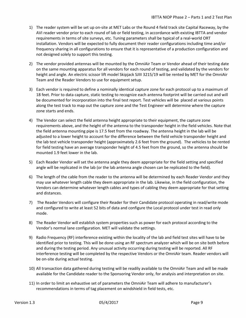
1) The reader system will be set up on-site at MET Labs or the Round 4 field track site Capital Raceway, by the AVI reader vendor prior to each round of lab or field testing, in accordance with existing IBTTA and vendor requirements in terms of site surveys, etc. Tuning parameters shall be typical of a real-world ORT installation. Vendors will be expected to fully document their reader configurations including time and/or frequency sharing in all configurations to ensure that it is representative of a production configuration and not designed solely to support this testing.
2) The vendor provided antennas will be mounted by the OmniAir Team or Vendor ahead of their testing date on the same mounting apparatus for all vendors for each round of testing, and validated by the vendors for height and angle. An electric scissor lift model Skipjack SJIII 3215/19 will be rented by MET for the OmniAir Team and the Reader Vendors to use for equipment setup.
3) Each vendor is required to define a nominally identical capture zone for each protocol up to a maximum of 18 feet. Prior to data capture, static testing to recognize each antenna footprint will be carried out and will be documented for incorporation into the final test report. Test vehicles will be placed at various points along the test track to map out the capture zone and the Test Engineer will determine where the capture zone starts and ends.
4) The Vendor can select the field antenna height appropriate to their equipment, the capture zone requirements above, and the height of the antenna to the transponder height in the field vehicles. Note that the field antenna mounting pipe is 17.5 feet from the roadway. The antenna height in the lab will be adjusted to a lower height to account for the difference between the field vehicle transponder height and the lab test vehicle transponder height (approximately 2.6 feet from the ground). The vehicles to be rented for field testing have an average transponder height of 4.5 feet from the ground, so the antenna should be mounted 1.9 feet lower in the lab.
5) Each Reader Vendor will set the antenna angle they deem appropriate for the field setting and specified angle will be replicated in the lab (or the lab antenna angle chosen can be replicated to the field).
6) The length of the cable from the reader to the antenna will be determined by each Reader Vendor and they may use whatever length cable they deem appropriate in the lab. Likewise, in the field configuration, the Vendors can determine whatever length cables and types of cabling they deem appropriate for that setting and distances.
7) The Reader Vendors will configure their Reader for their Candidate protocol operating in read/write mode and configured to write at least 52 bits of data and configure the Local protocol under test in read only mode.
8) The Reader Vendor will establish system properties such as power for each protocol according to the Vendor’s normal lane configuration. MET will validate the settings.
9) Radio Frequency (RF) interference existing within the locality of the lab and field test sites will have to be identified prior to testing. This will be done using an RF spectrum analyzer which will be on site both before and during the testing period. Any unusual activity occurring during testing will be reported. All RF interference testing will be completed by the respective Vendors or the OmniAir team. Reader vendors will be on-site during actual testing.
10) All transaction data gathered during testing will be readily available to the OmniAir Team and will be made available for the Candidate reader to the Sponsoring Vendor only, for analysis and interpretation on site.
11) In order to limit an exhaustive set of parameters the OmniAir Team will adhere to manufacturer’s recommendations in terms of tag placement on windshield in field tests, etc.
IBTTA NIOP Phase 2 – Parts 1 and 2 Test Plan
Version 1.3 05/4/2017 Page 10
12) Support staff from AVI Reader Vendors (3M, Kapsch and TransCore) will be available to the OmniAir Team prior to testing to confirm and verify reader parameters, as well as during the test conduct stage should any technological issues arise.
13) The OmniAir Team will supply limited different types of vehicles for the field test that match the windshield angle specified in Section 3.2 of this document.
14) During testing, only the reader system being tested will be active and all other reader systems will be powered off.
15) After being mounted in a test vehicle, each tag shall be read using the tag tester/handheld reader to ensure they are functional.
16) Due to timeout limitations, the time between gantry transits needs to be controlled so that the reader sees the tag as a new occurrence every transit (default time is 60 seconds since the last time the tag was written). This will require enough test vehicles to avoid the same transponder travelling more often than every 60 seconds.
17) Anomalies or apparent failures will be investigated by the OmniAir Team as further detailed in Section 5.3. All anomalies or failures will be fully documented for inclusion in the final report.
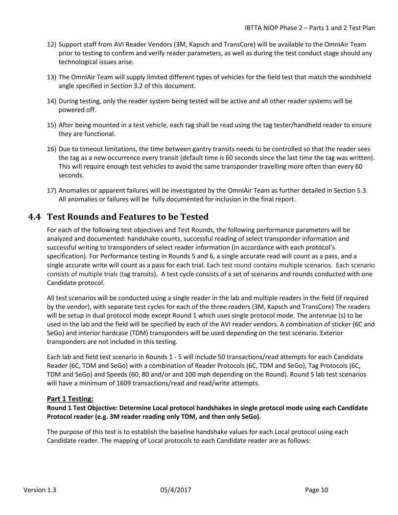
4.4 Test Rounds and Features to be Tested For each of the following test objectives and Test Rounds, the following performance parameters will be analyzed and documented: handshake counts, successful reading of select transponder information and successful writing to transponders of select reader information (in accordance with each protocol’s specification). For Performance testing in Rounds 5 and 6, a single accurate read will count as a pass, and a single accurate write will count as a pass for each trial. Each test round contains multiple scenarios. Each scenario consists of multiple trials (tag transits). A test cycle consists of a set of scenarios and rounds conducted with one Candidate protocol.
All test scenarios will be conducted using a single reader in the lab and multiple readers in the field (if required by the vendor), with separate test cycles for each of the three readers (3M, Kapsch and TransCore) The readers will be setup in dual protocol mode except Round 1 which uses single protocol mode. The antennae (s) to be used in the lab and the field will be specified by each of the AVI reader vendors. A combination of sticker (6C and SeGo) and interior hardcase (TDM) transponders will be used depending on the test scenario. Exterior transponders are not included in this testing.
Each lab and field test scenario in Rounds 1 - 5 will include 50 transactions/read attempts for each Candidate Reader (6C, TDM and SeGo) with a combination of Reader Protocols (6C, TDM and SeGo), Tag Protocols (6C, TDM and SeGo) and Speeds (60, 80 and/or and 100 mph depending on the Round). Round 5 lab test scenarios will have a minimum of 1609 transactions/read and read/write attempts.
Part 1 Testing: Round 1 Test Objective: Determine Local protocol handshakes in single protocol mode using each Candidate Protocol reader (e.g. 3M reader reading only TDM, and then only SeGo).
The purpose of this test is to establish the baseline handshake values for each Local protocol using each Candidate reader. The mapping of Local protocols to each Candidate reader are as follows:
IBTTA NIOP Phase 2 – Parts 1 and 2 Test Plan
Version 1.3 05/4/2017 Page 11
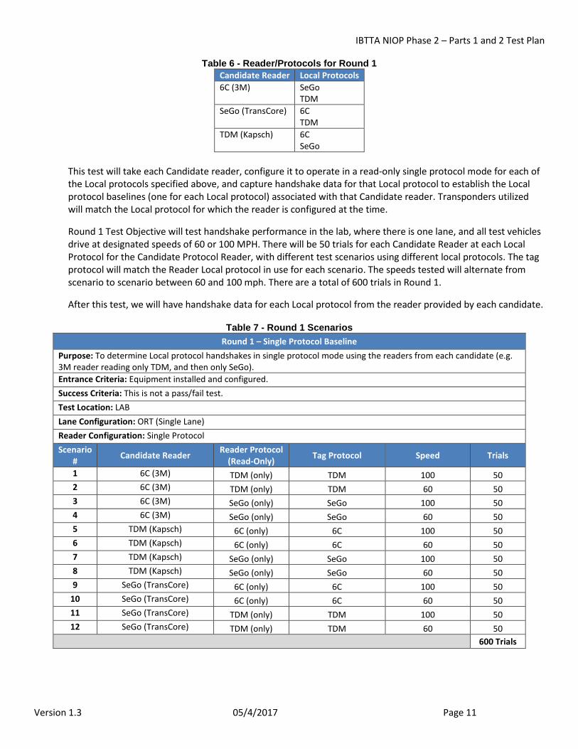
Table 6 - Reader/Protocols for Round 1 Candidate Reader Local Protocols 6C (3M) SeGo
TDM SeGo (TransCore) 6C
TDM TDM (Kapsch) 6C
SeGo This test will take each Candidate reader, configure it to operate in a read-only single protocol mode for each of the Local protocols specified above, and capture handshake data for that Local protocol to establish the Local protocol baselines (one for each Local protocol) associated with that Candidate reader. Transponders utilized will match the Local protocol for which the reader is configured at the time.
Round 1 Test Objective will test handshake performance in the lab, where there is one lane, and all test vehicles drive at designated speeds of 60 or 100 MPH. There will be 50 trials for each Candidate Reader at each Local Protocol for the Candidate Protocol Reader, with different test scenarios using different local protocols. The tag protocol will match the Reader Local protocol in use for each scenario. The speeds tested will alternate from scenario to scenario between 60 and 100 mph. There are a total of 600 trials in Round 1.
After this test, we will have handshake data for each Local protocol from the reader provided by each candidate.
Table 7 - Round 1 Scenarios Round 1 – Single Protocol Baseline
Purpose: To determine Local protocol handshakes in single protocol mode using the readers from each candidate (e.g. 3M reader reading only TDM, and then only SeGo). Entrance Criteria: Equipment installed and configured. Success Criteria: This is not a pass/fail test. Test Location: LAB Lane Configuration: ORT (Single Lane) Reader Configuration: Single Protocol Scenario
# Candidate Reader Reader Protocol (Read-Only) Tag Protocol Speed Trials
1 6C (3M) TDM (only) TDM 100 50 2 6C (3M) TDM (only) TDM 60 50 3 6C (3M) SeGo (only) SeGo 100 50 4 6C (3M) SeGo (only) SeGo 60 50 5 TDM (Kapsch) 6C (only) 6C 100 50 6 TDM (Kapsch) 6C (only) 6C 60 50 7 TDM (Kapsch) SeGo (only) SeGo 100 50 8 TDM (Kapsch) SeGo (only) SeGo 60 50 9 SeGo (TransCore) 6C (only) 6C 100 50
10 SeGo (TransCore) 6C (only) 6C 60 50 11 SeGo (TransCore) TDM (only) TDM 100 50 12 SeGo (TransCore) TDM (only) TDM 60 50
600 Trials
IBTTA NIOP Phase 2 – Parts 1 and 2 Test Plan
Version 1.3 05/4/2017 Page 12
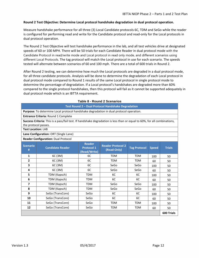
Round 2 Test Objective: Determine Local protocol handshake degradation in dual protocol operation.
Measure handshake performance for all three (3) Local Candidate protocols 6C, TDM and SeGo while the reader is configured for performing read and write for the Candidate protocol and read-only for the Local protocols in dual protocol operation.
The Round 2 Test Objective will test handshake performance in the lab, and all test vehicles drive at designated speeds of 60 or 100 MPH. There will be 50 trials for each Candidate Reader in dual protocol mode with the Candidate Protocol in read/write mode and Local protocol in read only mode, and different scenarios using different Local Protocols. The tag protocol will match the Local protocol in use for each scenario. The speeds tested will alternate between scenarios of 60 and 100 mph. There are a total of 600 trials in Round 2.
After Round 2 testing, we can determine how much the Local protocols are degraded in a dual protocol mode, for all three candidate protocols. Analysis will be done to determine the degradation of each Local protocol in dual protocol mode compared to Round 1 results of the same Local protocol in single protocol mode to determine the percentage of degradation. If a Local protocol’s handshakes are degraded more than 60% compared to the single protocol handshakes, then this protocol will fail as it cannot be supported adequately in dual protocol mode which is an IBTTA requirement.
Table 8 - Round 2 Scenarios Test Round 2 – Dual Protocol Handshake Degradation
Purpose: To determine Local protocol handshake degradation in dual protocol operation. Entrance Criteria: Round 1 Complete Success Criteria: This is a pass/fail test. If handshake degradation is less than or equal to 60%, for all combinations, the protocol passes. Test Location: LAB Lane Configuration: ORT (Single Lane) Reader Configuration: Dual Protocol
Scenario # Candidate Reader
Reader Protocol 1
(Read/Write)
Reader Protocol 2 (Read-Only) Tag Protocol Speed Trials
1 6C (3M) 6C TDM TDM 100 50 2 6C (3M) 6C TDM TDM 60 50 3 6C (3M) 6C SeGo SeGo 100 50 4 6C (3M) 6C SeGo SeGo 60 50 5 TDM (Kapsch) TDM 6C 6C 100 50 6 TDM (Kapsch) TDM 6C 6C 60 50 7 TDM (Kapsch) TDM SeGo SeGo 100 50 8 TDM (Kapsch) TDM SeGo SeGo 60 50 9 SeGo (TransCore) SeGo 6C 6C 100 50
10 SeGo (TransCore) SeGo 6C 6C 60 50 11 SeGo (TransCore) SeGo TDM TDM 100 50 12 SeGo (TransCore) SeGo TDM TDM 60 50
600 Trials
IBTTA NIOP Phase 2 – Parts 1 and 2 Test Plan
Version 1.3 05/4/2017 Page 13
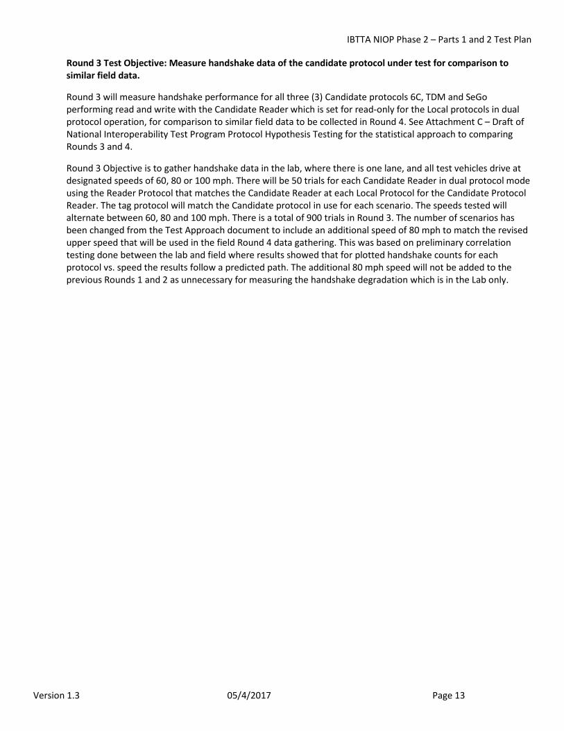
Round 3 Test Objective: Measure handshake data of the candidate protocol under test for comparison to similar field data.
Round 3 will measure handshake performance for all three (3) Candidate protocols 6C, TDM and SeGo performing read and write with the Candidate Reader which is set for read-only for the Local protocols in dual protocol operation, for comparison to similar field data to be collected in Round 4. See Attachment C – Draft of National Interoperability Test Program Protocol Hypothesis Testing for the statistical approach to comparing Rounds 3 and 4.
Round 3 Objective is to gather handshake data in the lab, where there is one lane, and all test vehicles drive at designated speeds of 60, 80 or 100 mph. There will be 50 trials for each Candidate Reader in dual protocol mode using the Reader Protocol that matches the Candidate Reader at each Local Protocol for the Candidate Protocol Reader. The tag protocol will match the Candidate protocol in use for each scenario. The speeds tested will alternate between 60, 80 and 100 mph. There is a total of 900 trials in Round 3. The number of scenarios has been changed from the Test Approach document to include an additional speed of 80 mph to match the revised upper speed that will be used in the field Round 4 data gathering. This was based on preliminary correlation testing done between the lab and field where results showed that for plotted handshake counts for each protocol vs. speed the results follow a predicted path. The additional 80 mph speed will not be added to the previous Rounds 1 and 2 as unnecessary for measuring the handshake degradation which is in the Lab only.
IBTTA NIOP Phase 2 – Parts 1 and 2 Test Plan
Version 1.3 05/4/2017 Page 14
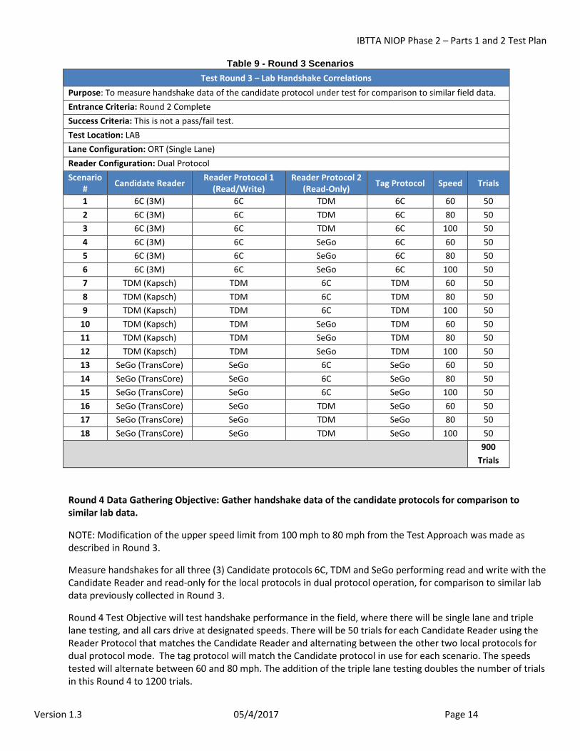
Table 9 - Round 3 Scenarios Test Round 3 – Lab Handshake Correlations
Purpose: To measure handshake data of the candidate protocol under test for comparison to similar field data. Entrance Criteria: Round 2 Complete Success Criteria: This is not a pass/fail test. Test Location: LAB Lane Configuration: ORT (Single Lane) Reader Configuration: Dual Protocol Scenario
# Candidate Reader Reader Protocol 1 (Read/Write)
Reader Protocol 2 (Read-Only) Tag Protocol Speed Trials
1 6C (3M) 6C TDM 6C 60 50 2 6C (3M) 6C TDM 6C 80 50 3 6C (3M) 6C TDM 6C 100 50 4 6C (3M) 6C SeGo 6C 60 50 5 6C (3M) 6C SeGo 6C 80 50 6 6C (3M) 6C SeGo 6C 100 50 7 TDM (Kapsch) TDM 6C TDM 60 50 8 TDM (Kapsch) TDM 6C TDM 80 50 9 TDM (Kapsch) TDM 6C TDM 100 50
10 TDM (Kapsch) TDM SeGo TDM 60 50 11 TDM (Kapsch) TDM SeGo TDM 80 50 12 TDM (Kapsch) TDM SeGo TDM 100 50 13 SeGo (TransCore) SeGo 6C SeGo 60 50 14 SeGo (TransCore) SeGo 6C SeGo 80 50 15 SeGo (TransCore) SeGo 6C SeGo 100 50 16 SeGo (TransCore) SeGo TDM SeGo 60 50 17 SeGo (TransCore) SeGo TDM SeGo 80 50 18 SeGo (TransCore) SeGo TDM SeGo 100 50
900 Trials
Round 4 Data Gathering Objective: Gather handshake data of the candidate protocols for comparison to similar lab data.
NOTE: Modification of the upper speed limit from 100 mph to 80 mph from the Test Approach was made as described in Round 3.
Measure handshakes for all three (3) Candidate protocols 6C, TDM and SeGo performing read and write with the Candidate Reader and read-only for the local protocols in dual protocol operation, for comparison to similar lab data previously collected in Round 3.
Round 4 Test Objective will test handshake performance in the field, where there will be single lane and triple lane testing, and all cars drive at designated speeds. There will be 50 trials for each Candidate Reader using the Reader Protocol that matches the Candidate Reader and alternating between the other two local protocols for dual protocol mode. The tag protocol will match the Candidate protocol in use for each scenario. The speeds tested will alternate between 60 and 80 mph. The addition of the triple lane testing doubles the number of trials in this Round 4 to 1200 trials.
IBTTA NIOP Phase 2 – Parts 1 and 2 Test Plan
Version 1.3 05/4/2017 Page 15
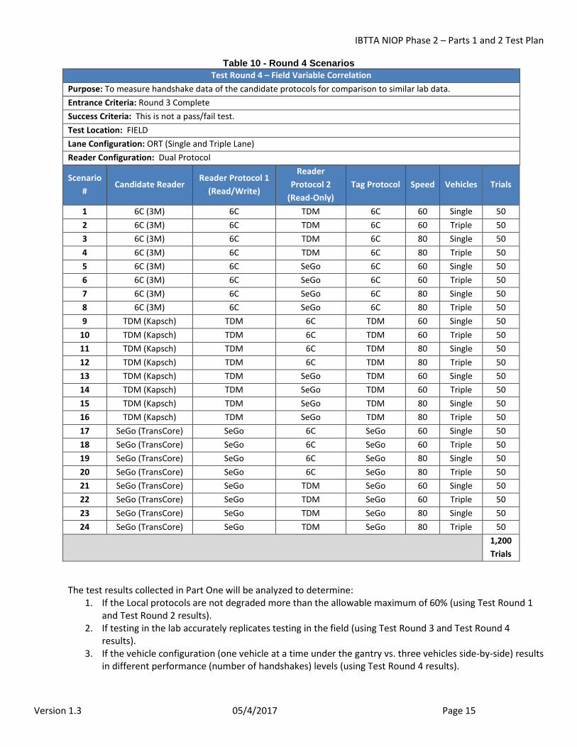
Table 10 - Round 4 Scenarios Test Round 4 – Field Variable Correlation
Purpose: To measure handshake data of the candidate protocols for comparison to similar lab data. Entrance Criteria: Round 3 Complete Success Criteria: This is not a pass/fail test. Test Location: FIELD Lane Configuration: ORT (Single and Triple Lane) Reader Configuration: Dual Protocol
Scenario #
Candidate Reader Reader Protocol 1
(Read/Write)
Reader Protocol 2
(Read-Only) Tag Protocol Speed Vehicles Trials
1 6C (3M) 6C TDM 6C 60 Single 50 2 6C (3M) 6C TDM 6C 60 Triple 50 3 6C (3M) 6C TDM 6C 80 Single 50 4 6C (3M) 6C TDM 6C 80 Triple 50 5 6C (3M) 6C SeGo 6C 60 Single 50 6 6C (3M) 6C SeGo 6C 60 Triple 50 7 6C (3M) 6C SeGo 6C 80 Single 50 8 6C (3M) 6C SeGo 6C 80 Triple 50 9 TDM (Kapsch) TDM 6C TDM 60 Single 50
10 TDM (Kapsch) TDM 6C TDM 60 Triple 50 11 TDM (Kapsch) TDM 6C TDM 80 Single 50 12 TDM (Kapsch) TDM 6C TDM 80 Triple 50 13 TDM (Kapsch) TDM SeGo TDM 60 Single 50 14 TDM (Kapsch) TDM SeGo TDM 60 Triple 50 15 TDM (Kapsch) TDM SeGo TDM 80 Single 50 16 TDM (Kapsch) TDM SeGo TDM 80 Triple 50 17 SeGo (TransCore) SeGo 6C SeGo 60 Single 50 18 SeGo (TransCore) SeGo 6C SeGo 60 Triple 50 19 SeGo (TransCore) SeGo 6C SeGo 80 Single 50 20 SeGo (TransCore) SeGo 6C SeGo 80 Triple 50 21 SeGo (TransCore) SeGo TDM SeGo 60 Single 50 22 SeGo (TransCore) SeGo TDM SeGo 60 Triple 50 23 SeGo (TransCore) SeGo TDM SeGo 80 Single 50 24 SeGo (TransCore) SeGo TDM SeGo 80 Triple 50
1,200 Trials
The test results collected in Part One will be analyzed to determine: 1. If the Local protocols are not degraded more than the allowable maximum of 60% (using Test Round 1
and Test Round 2 results). 2. If testing in the lab accurately replicates testing in the field (using Test Round 3 and Test Round 4
results). 3. If the vehicle configuration (one vehicle at a time under the gantry vs. three vehicles side-by-side) results
in different performance (number of handshakes) levels (using Test Round 4 results).

IBTTA NIOP Phase 2 – Parts 1 and 2 Test Plan
Version 1.3 05/4/2017 Page 16
Part Two Testing:
Round 5 Test Objective: Determine read and write performance of candidate protocols under various configurations.
Determine read and write performance for all three (3) Candidate protocols 6C, TDM and SeGo performing read and write with the Candidate protocol configured read-only for the Local protocols in dual protocol operation.
For planning Part Two of the performance testing, OmniAir assumes the lab will be shown to be an acceptable surrogate for the field based on results of the Part One tests. This assumption makes it possible to perform most of the read and write performance tests in the lab.
Round 5 Test Objective will measure read and write performance in the lab, where there is one lane, and all test vehicles drive at designated speeds of 60 and also 100 MPH. There will be 1,609 – 3,812 trials for each Candidate Reader using the Reader Protocol that matches the Candidate Reader at each Local Protocol for the Candidate Protocol Reader in dual protocol mode. The tag protocol will match the Candidate protocol in use for each scenario. The speeds tested will alternate between 60 and 100 mph between different scenarios. The increased number of trials gives us the amount necessary for statistical significance. There is a total of 19,308 - 45,744 trials in Round 5.
Note: All twelve of these test scenarios will be performed, regardless of outcome of previous Round 5 tests. Each test will result in: a pass; a fail; or an inconclusive result. A pass or fail can occur at an intermediate point (with as little as 1,609 trials) if the number of trial failures meets the criteria in Table 18 of this Test Plan.
Table 11 - Round 5 Scenarios Test Round 5 – Read and Write Performance
Purpose: To determine read and write performance of candidate protocols under various configurations. Entrance Criteria: Part One Complete & Positive Lab/Field Correlation Shown Success Criteria: See discussion Test Location: LAB Lane Configuration: ORT (Single Lane) Reader Configuration: Dual Protocol Scenario
# Candidate Reader
Scenarios Reader Protocol 1
(Read/Write) Reader Protocol 2
(Read-Only) Tag Protocol Speed Trials
1 6C (3M) 6C TDM 6C 100 1,609-3,812 2 6C (3M) 6C TDM 6C 60 1,609-3,812 3 6C (3M) 6C SeGo 6C 100 1,609-3,812 4 6C (3M) 6C SeGo 6C 60 1,609-3,812 5 TDM (Kapsch) TDM 6C TDM 100 1,609-3,812 6 TDM (Kapsch) TDM 6C TDM 60 1,609-3,812 7 TDM (Kapsch) TDM SeGo TDM 100 1,609-3,812 8 TDM (Kapsch) TDM SeGo TDM 60 1,609-3,812 9 SeGo (TransCore) SeGo 6C SeGo 100 1,609-3,812
10 SeGo (TransCore) SeGo 6C SeGo 60 1,609-3,812 11 SeGo (TransCore) SeGo TDM SeGo 100 1,609-3,812 12 SeGo (TransCore) SeGo TDM SeGo 60 1,609-3,812
19,308 - 45,744 Trials
IBTTA NIOP Phase 2 – Parts 1 and 2 Test Plan
Version 1.3 05/4/2017 Page 17
Part Three Testing:
Round 6 Test Objective: Determine read and write performance of candidate protocols when three vehicles are simultaneously in the ORT zone.
After completion of Parts One and Two, the following data will be available for consideration by IBTTA: 1. The results of the lab testing in Part Two. This will include which read and write tests have passed,
failed, or were inconclusive. 2. Whether there are correlations proven in Part One (Rounds 3 and 4) that testing is necessary to cover all
the required variable combinations (e.g. single lane vs. three lane). 3. An accurate current budget, based on the cost and schedules to complete the lab testing in Part Two.
Note this could vary significantly based on Part Two’s range of required tests (19,308 – 45,744 trials).
Using the information in the list above, OmniAir will work with IBTTA to finalize the tests to be run in Part Three, including determination of:
1. Which protocols will be field tested (after consideration of the pass/fail/inconclusive results in Part Two).
2. Which combinations of variables remain to be tested (after consideration of the correlation testing in Part one – single vs. three lanes, speed).
See future deliverable, Phase 2 – Part 3 Test Plan, for Round 6 details.
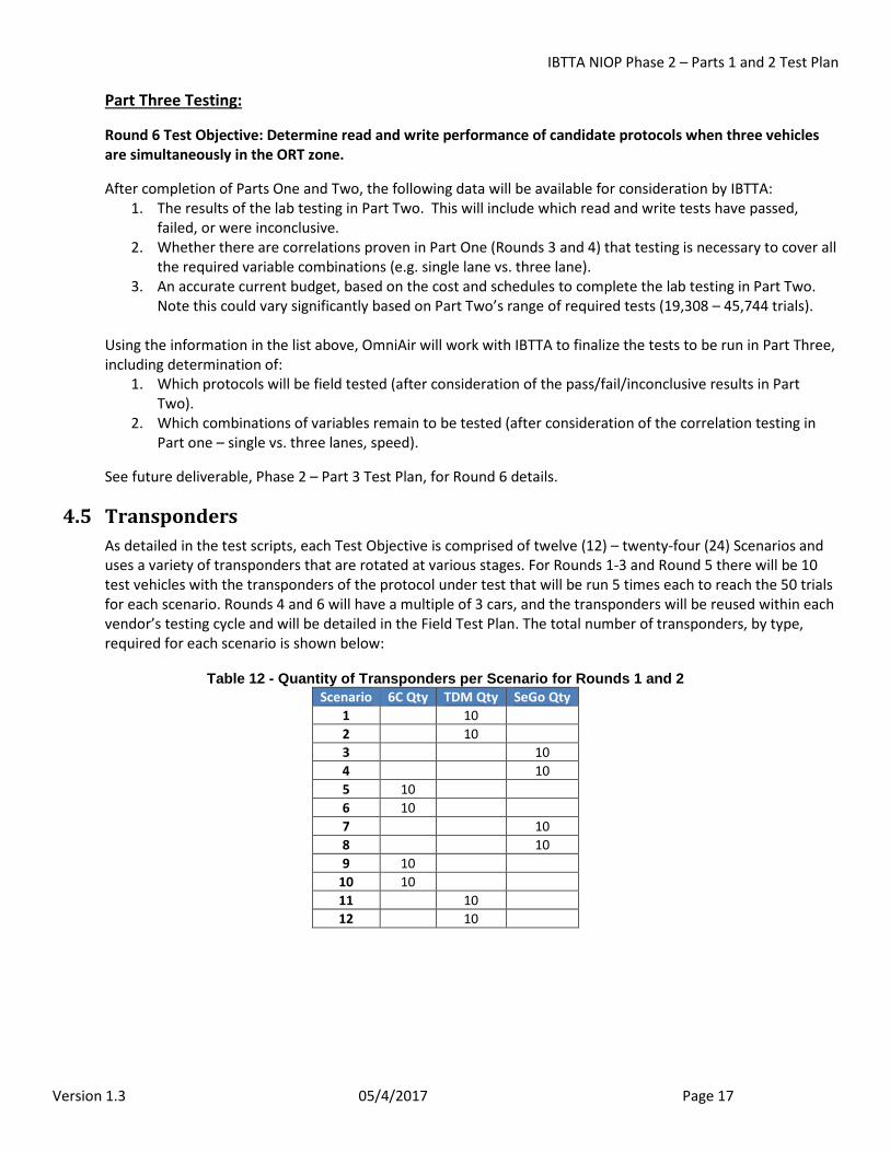
4.5 Transponders As detailed in the test scripts, each Test Objective is comprised of twelve (12) – twenty-four (24) Scenarios and uses a variety of transponders that are rotated at various stages. For Rounds 1-3 and Round 5 there will be 10 test vehicles with the transponders of the protocol under test that will be run 5 times each to reach the 50 trials for each scenario. Rounds 4 and 6 will have a multiple of 3 cars, and the transponders will be reused within each vendor’s testing cycle and will be detailed in the Field Test Plan. The total number of transponders, by type, required for each scenario is shown below:
Table 12 - Quantity of Transponders per Scenario for Rounds 1 and 2 Scenario 6C Qty TDM Qty SeGo Qty
1 10 2 10 3 10 4 10 5 10 6 10 7 10 8 10 9 10
10 10 11 10 12 10
IBTTA NIOP Phase 2 – Parts 1 and 2 Test Plan
Version 1.3 05/4/2017 Page 18
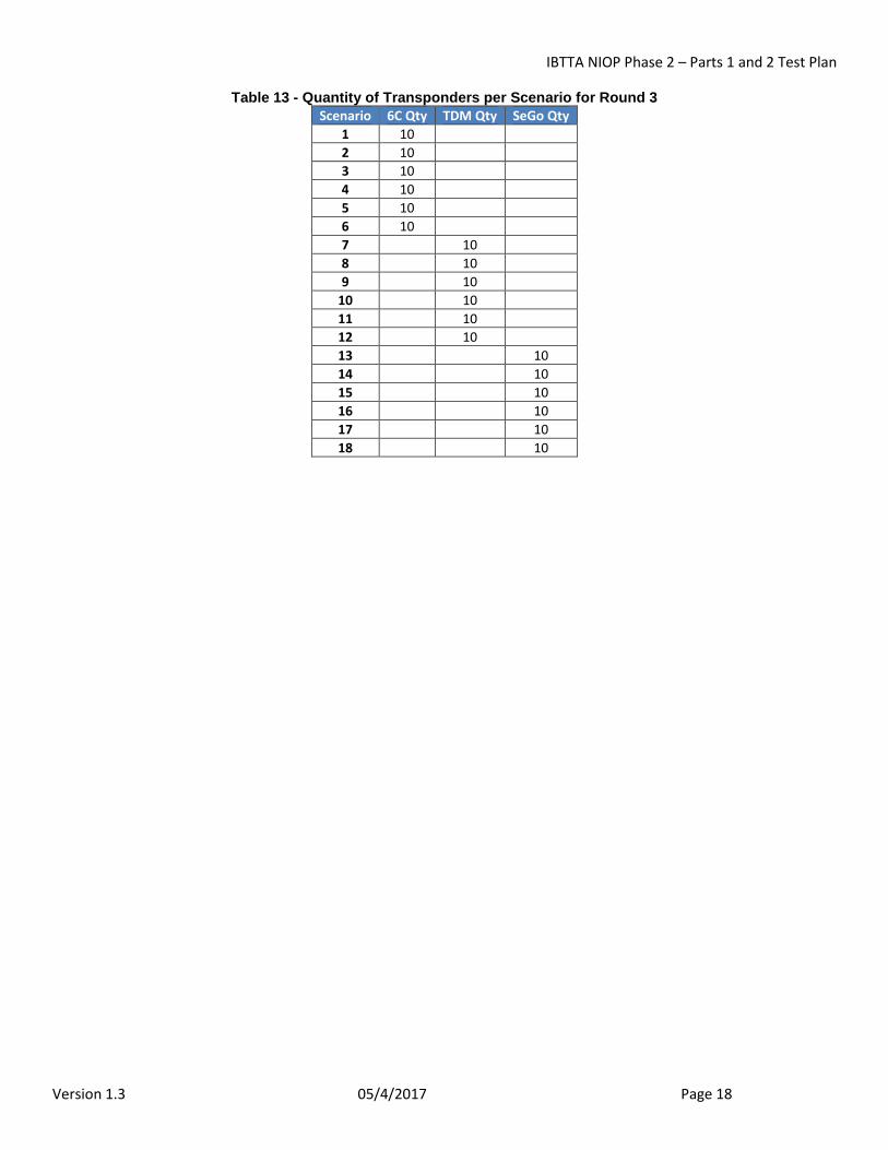
Table 13 - Quantity of Transponders per Scenario for Round 3 Scenario 6C Qty TDM Qty SeGo Qty
1 10 2 10 3 10 4 10 5 10 6 10 7 10 8 10 9 10
10 10 11 10 12 10 13 10 14 10 15 10 16 10 17 10 18 10
IBTTA NIOP Phase 2 – Parts 1 and 2 Test Plan
Version 1.3 05/4/2017 Page 19
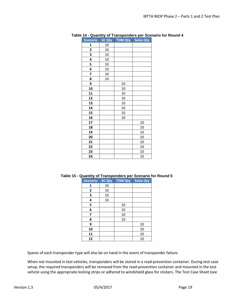
Table 14 - Quantity of Transponders per Scenario for Round 4 Scenario 6C Qty TDM Qty SeGo Qty
1 10 2 10 3 10 4 10 5 10 6 10 7 10 8 10 9 10
10 10 11 10 12 10 13 10 14 10 15 10 16 10 17 10 18 10 19 10 20 10 21 10 22 10 23 10 24 10
Table 15 - Quantity of Transponders per Scenario for Round 5 Scenario 6C Qty TDM Qty SeGo Qty
1 10 2 10 3 10 4 10 5 10 6 10 7 10 8 10 9 10
10 10 11 10 12 10
Spares of each transponder type will also be on hand in the event of transponder failure.
When not mounted in test vehicles, transponders will be stored in a read-prevention container. During test case setup, the required transponders will be removed from the read-prevention container and mounted in the test vehicle using the appropriate locking strips or adhered to windshield glass for stickers. The Test Case Sheet (see
IBTTA NIOP Phase 2 – Parts 1 and 2 Test Plan
Version 1.3 05/4/2017 Page 20
Attachment A) will be filled out to document transponder assignment. Attachment A will also be used to manually track each iteration of each test case and note any observed anomalies.
The test case setup/staging area will be located to prevent any potential transponder reads during the setup process.
Upon removal from a test vehicle (either when required based on transponder rotation or due to transponder failure), transponders will be returned directly to the read-prevention container.
4.6 Vehicles/Drivers At the start of each day’s field testing in Round 4 and Round 6 (if executed), the Driver Test Sheet (Attachment D) and Vehicle Test Sheet (Attachment E) will be completed for inclusion in the test report.
4.7 Data Capture Each reader system will be connected to a laptop for data capture purposes.
The laptop will be connected to the lane controller port(s) of the reader(s). The laptop will be configured with software that will capture and log all messages from the reader in their original format with an associated date/time stamp as well as identifiers for the reader and channel on which the message was received. In addition, the software will translate the transponder read and write messages into readable ASCII format with delimiters between all fields to allow for easy identification of all transponder data elements as well as to ease importing into other software (e.g., MS Excel) for analysis purposes.
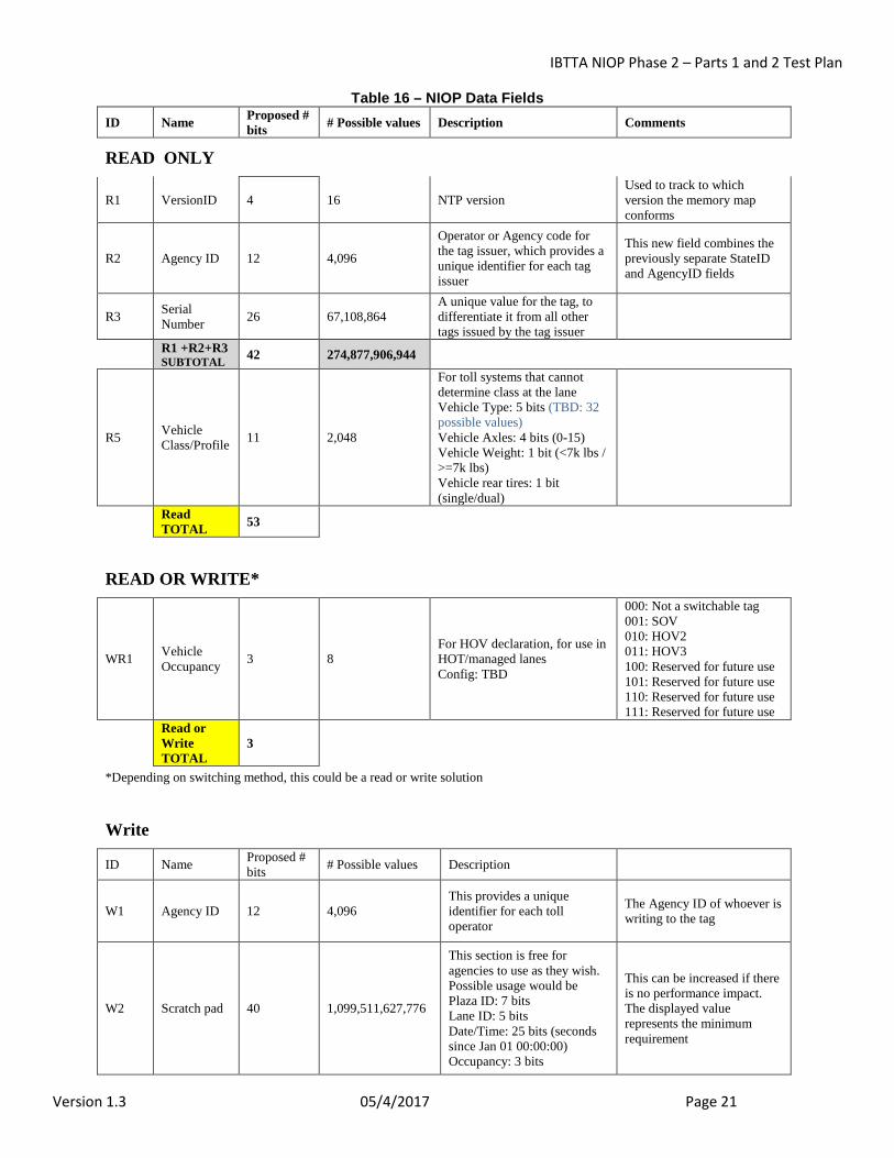
There is a generic minimum number of bits to be read and written for all protocols under test as specified in the Final Draft NIOP Requirements Document v2.2014.09. final amended CLEAN Section 3.8.1.2:
Fixed Data Storage – Minimum Requirements – Read While the fields below are proposed for NIOP, they are not a requirement for NIOP testing. Each protocol currently supports Agency ID and Tag Serial Number at a minimum and it is those fields that we are using to verify the read. The VersionID and Vehicle Class/Profile fields will not be used.
IBTTA NIOP Phase 2 – Parts 1 and 2 Test Plan
Version 1.3 05/4/2017 Page 21
Table 16 – NIOP Data Fields ID Name Proposed #
bits # Possible values Description Comments
READ ONLY
R1 VersionID 4 16 NTP version Used to track to which version the memory map conforms
R2 Agency ID 12 4,096
Operator or Agency code for the tag issuer, which provides a unique identifier for each tag issuer
This new field combines the previously separate StateID and AgencyID fields
R3 Serial Number 26 67,108,864
A unique value for the tag, to differentiate it from all other tags issued by the tag issuer
R1 +R2+R3 SUBTOTAL 42 274,877,906,944
R5 Vehicle Class/Profile 11 2,048
For toll systems that cannot determine class at the lane Vehicle Type: 5 bits (TBD: 32 possible values) Vehicle Axles: 4 bits (0-15) Vehicle Weight: 1 bit (<7k lbs / >=7k lbs) Vehicle rear tires: 1 bit (single/dual)
Read TOTAL 53
READ OR WRITE*
WR1 Vehicle Occupancy 3 8
For HOV declaration, for use in HOT/managed lanes Config: TBD
000: Not a switchable tag 001: SOV 010: HOV2 011: HOV3 100: Reserved for future use 101: Reserved for future use 110: Reserved for future use 111: Reserved for future use
Read or Write TOTAL
3
*Depending on switching method, this could be a read or write solution
Write
ID Name Proposed # bits # Possible values Description
W1 Agency ID 12 4,096 This provides a unique identifier for each toll operator
The Agency ID of whoever is writing to the tag
W2 Scratch pad 40 1,099,511,627,776
This section is free for agencies to use as they wish. Possible usage would be Plaza ID: 7 bits Lane ID: 5 bits Date/Time: 25 bits (seconds since Jan 01 00:00:00) Occupancy: 3 bits
This can be increased if there is no performance impact. The displayed value represents the minimum requirement
IBTTA NIOP Phase 2 – Parts 1 and 2 Test Plan
Version 1.3 05/4/2017 Page 22
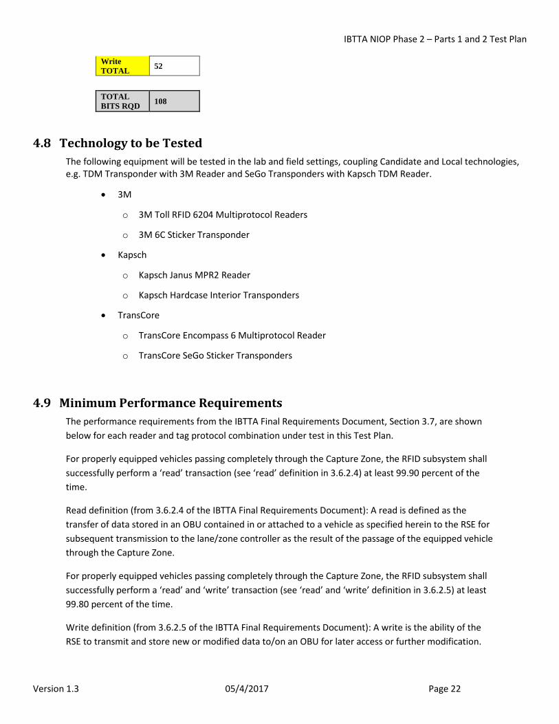
Write TOTAL 52
TOTAL BITS RQD 108
4.8 Technology to be Tested The following equipment will be tested in the lab and field settings, coupling Candidate and Local technologies, e.g. TDM Transponder with 3M Reader and SeGo Transponders with Kapsch TDM Reader.
• 3M
o 3M Toll RFID 6204 Multiprotocol Readers
o 3M 6C Sticker Transponder
• Kapsch
o Kapsch Janus MPR2 Reader
o Kapsch Hardcase Interior Transponders
• TransCore
o TransCore Encompass 6 Multiprotocol Reader
o TransCore SeGo Sticker Transponders
4.9 Minimum Performance Requirements The performance requirements from the IBTTA Final Requirements Document, Section 3.7, are shown below for each reader and tag protocol combination under test in this Test Plan.
For properly equipped vehicles passing completely through the Capture Zone, the RFID subsystem shall successfully perform a ‘read’ transaction (see ‘read’ definition in 3.6.2.4) at least 99.90 percent of the time.
Read definition (from 3.6.2.4 of the IBTTA Final Requirements Document): A read is defined as the transfer of data stored in an OBU contained in or attached to a vehicle as specified herein to the RSE for subsequent transmission to the lane/zone controller as the result of the passage of the equipped vehicle through the Capture Zone.
For properly equipped vehicles passing completely through the Capture Zone, the RFID subsystem shall successfully perform a ‘read’ and ‘write’ transaction (see ‘read’ and ‘write’ definition in 3.6.2.5) at least 99.80 percent of the time.
Write definition (from 3.6.2.5 of the IBTTA Final Requirements Document): A write is the ability of the RSE to transmit and store new or modified data to/on an OBU for later access or further modification.
IBTTA NIOP Phase 2 – Parts 1 and 2 Test Plan
Version 1.3 05/4/2017 Page 23
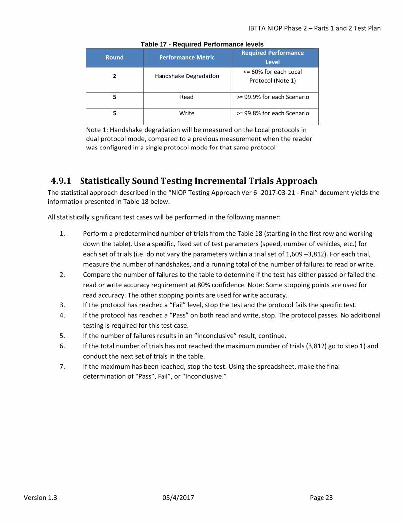
Table 17 - Required Performance levels
Round Performance Metric Required Performance
Level
2 Handshake Degradation <= 60% for each Local
Protocol (Note 1)
5 Read >= 99.9% for each Scenario
5 Write >= 99.8% for each Scenario
Note 1: Handshake degradation will be measured on the Local protocols in dual protocol mode, compared to a previous measurement when the reader was configured in a single protocol mode for that same protocol
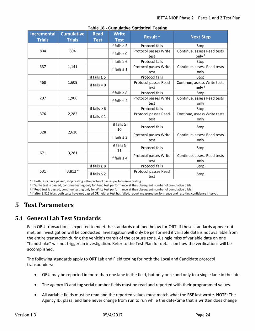
4.9.1 Statistically Sound Testing Incremental Trials Approach The statistical approach described in the “NIOP Testing Approach Ver 6 -2017-03-21 - Final” document yields the information presented in Table 18 below.
All statistically significant test cases will be performed in the following manner:
1. Perform a predetermined number of trials from the Table 18 (starting in the first row and working down the table). Use a specific, fixed set of test parameters (speed, number of vehicles, etc.) for each set of trials (i.e. do not vary the parameters within a trial set of 1,609 –3,812). For each trial, measure the number of handshakes, and a running total of the number of failures to read or write.
2. Compare the number of failures to the table to determine if the test has either passed or failed the read or write accuracy requirement at 80% confidence. Note: Some stopping points are used for read accuracy. The other stopping points are used for write accuracy.
3. If the protocol has reached a “Fail” level, stop the test and the protocol fails the specific test. 4. If the protocol has reached a “Pass” on both read and write, stop. The protocol passes. No additional
testing is required for this test case. 5. If the number of failures results in an “inconclusive” result, continue. 6. If the total number of trials has not reached the maximum number of trials (3,812) go to step 1) and
conduct the next set of trials in the table. 7. If the maximum has been reached, stop the test. Using the spreadsheet, make the final
determination of “Pass”, Fail”, or “Inconclusive.”
IBTTA NIOP Phase 2 – Parts 1 and 2 Test Plan
Version 1.3 05/4/2017 Page 24
Table 18 - Cumulative Statistical Testing Incremental
Trials Cumulative
Trials Read Test
Write Test Result 1 Next Step
804 804 if fails ≥ 5 Protocol fails Stop
if fails = 0 Protocol passes Write test
Continue, assess Read tests only 2
337 1,141 if fails ≥ 6 Protocol fails Stop
if fails ≤ 1 Protocol passes Write test
Continue, assess Read tests only
468 1,609 if fails ≥ 5 Protocol fails Stop
if fails = 0 Protocol passes Read test
Continue, assess Write tests only 3
297 1,906 if fails ≥ 8 Protocol fails Stop
if fails ≤ 2 Protocol passes Write test
Continue, assess Read tests only
376 2,282 if fails ≥ 6 Protocol fails Stop
if fails ≤ 1 Protocol passes Read test
Continue, assess Write tests only
328 2,610 if fails ≥
10 Protocol fails Stop
if fails ≤ 3 Protocol passes Write test
Continue, assess Read tests only
671 3,281 if fails ≥
11 Protocol fails Stop
if fails ≤ 4 Protocol passes Write test
Continue, assess Read tests only
531 3,812 4 if fails ≥ 8 Protocol fails Stop
if fails ≤ 2 Protocol passes Read test Stop
1 If both tests have passed, stop testing – the protocol passes performance testing. 2 If Write test is passed, continue testing only for Read test performance at the subsequent number of cumulative trials. 3 If Read test is passed, continue testing only for Write test performance at the subsequent number of cumulative trials. 4 If after 3,812 trials both tests have not passed OR neither test has failed, report measured performance and resulting confidence interval.
5 Test Parameters
5.1 General Lab Test Standards Each OBU transaction is expected to meet the standards outlined below for ORT. If these standards appear not met, an investigation will be conducted. Investigation will only be performed if variable data is not available from the entire transaction during the vehicle’s transit of the capture zone. A single miss of variable data on one “handshake” will not trigger an investigation. Refer to the Test Plan for details on how the verifications will be accomplished.
The following standards apply to ORT Lab and Field testing for both the Local and Candidate protocol transponders:
• OBU may be reported in more than one lane in the field, but only once and only to a single lane in the lab.
• The agency ID and tag serial number fields must be read and reported with their programmed values.
• All variable fields must be read and the reported values must match what the RSE last wrote. NOTE: The Agency ID, plaza, and lane never change from run to run while the date/time that is written does change
IBTTA NIOP Phase 2 – Parts 1 and 2 Test Plan
Version 1.3 05/4/2017 Page 25
from run to run. The only way to actually verify that the write was successful on a tag that has been used in a previous run is to use the date/time.
• No OBUs are reported that have not traveled through a lane.
5.2 Test Details
5.2.1 Equipment The equipment will meet the following conditions to run the test:
Table 19 - Equipment Conditions
Item Condition
Reader Sending data to RECORDING SYSTEM. No failed modules or other reported anomalies.
Recording System (RS) The RECORDING SYSTEM is comprised of a laptop logging all data generated by the RSE of all test runs.
Laptop is functional and logging data.
OBUs OBU Tester indicates that OBU is working properly.
Test Vehicles Test track simulated cars in functional condition.
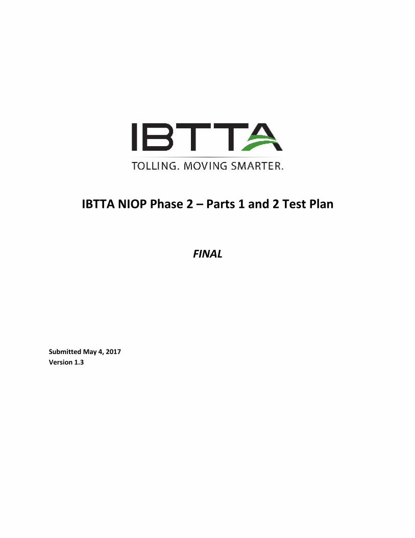
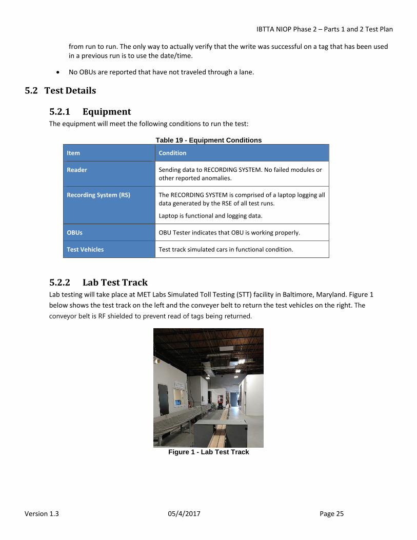
5.2.2 Lab Test Track Lab testing will take place at MET Labs Simulated Toll Testing (STT) facility in Baltimore, Maryland. Figure 1 below shows the test track on the left and the conveyer belt to return the test vehicles on the right. The conveyor belt is RF shielded to prevent read of tags being returned.
Figure 1 - Lab Test Track
IBTTA NIOP Phase 2 – Parts 1 and 2 Test Plan
Version 1.3 05/4/2017 Page 26
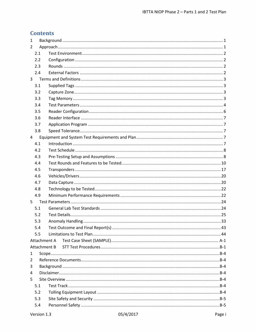
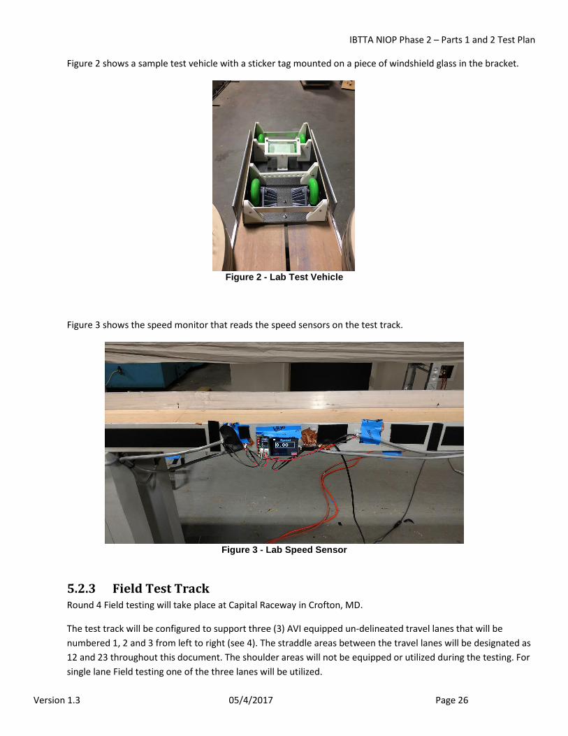
Figure 2 shows a sample test vehicle with a sticker tag mounted on a piece of windshield glass in the bracket.
Figure 2 - Lab Test Vehicle
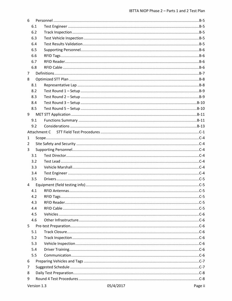
Figure 3 shows the speed monitor that reads the speed sensors on the test track.
Figure 3 - Lab Speed Sensor
5.2.3 Field Test Track Round 4 Field testing will take place at Capital Raceway in Crofton, MD.
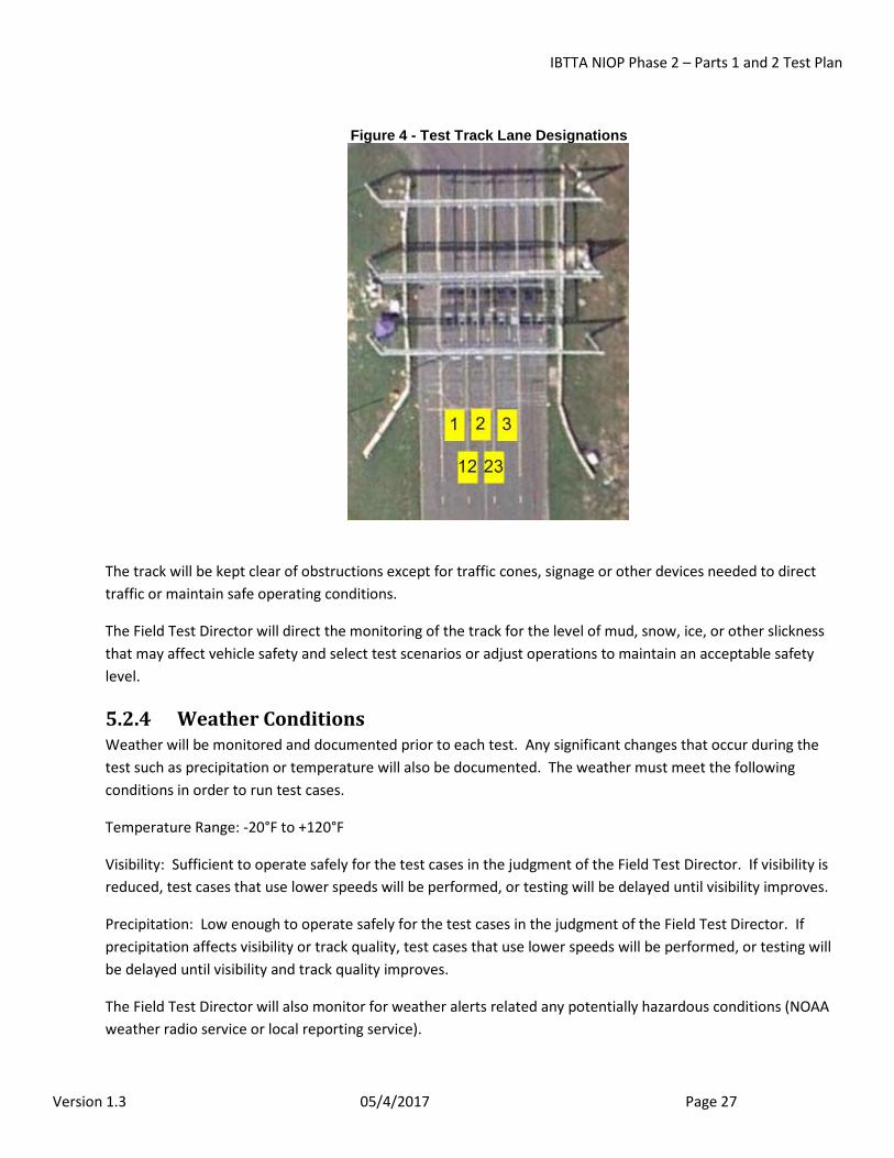
The test track will be configured to support three (3) AVI equipped un-delineated travel lanes that will be numbered 1, 2 and 3 from left to right (see 4). The straddle areas between the travel lanes will be designated as 12 and 23 throughout this document. The shoulder areas will not be equipped or utilized during the testing. For single lane Field testing one of the three lanes will be utilized.
IBTTA NIOP Phase 2 – Parts 1 and 2 Test Plan
Version 1.3 05/4/2017 Page 27
Figure 4 - Test Track Lane Designations
The track will be kept clear of obstructions except for traffic cones, signage or other devices needed to direct traffic or maintain safe operating conditions.
The Field Test Director will direct the monitoring of the track for the level of mud, snow, ice, or other slickness that may affect vehicle safety and select test scenarios or adjust operations to maintain an acceptable safety level.
5.2.4 Weather Conditions Weather will be monitored and documented prior to each test. Any significant changes that occur during the test such as precipitation or temperature will also be documented. The weather must meet the following conditions in order to run test cases.
Temperature Range: -20°F to +120°F
Visibility: Sufficient to operate safely for the test cases in the judgment of the Field Test Director. If visibility is reduced, test cases that use lower speeds will be performed, or testing will be delayed until visibility improves.
Precipitation: Low enough to operate safely for the test cases in the judgment of the Field Test Director. If precipitation affects visibility or track quality, test cases that use lower speeds will be performed, or testing will be delayed until visibility and track quality improves.
The Field Test Director will also monitor for weather alerts related any potentially hazardous conditions (NOAA weather radio service or local reporting service).
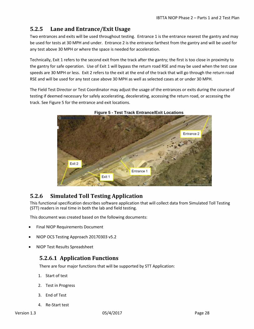
IBTTA NIOP Phase 2 – Parts 1 and 2 Test Plan
Version 1.3 05/4/2017 Page 28
5.2.5 Lane and Entrance/Exit Usage Two entrances and exits will be used throughout testing. Entrance 1 is the entrance nearest the gantry and may be used for tests at 30 MPH and under. Entrance 2 is the entrance farthest from the gantry and will be used for any test above 30 MPH or where the space is needed for acceleration.
Technically, Exit 1 refers to the second exit from the track after the gantry; the first is too close in proximity to the gantry for safe operation. Use of Exit 1 will bypass the return road RSE and may be used when the test case speeds are 30 MPH or less. Exit 2 refers to the exit at the end of the track that will go through the return road RSE and will be used for any test case above 30 MPH as well as selected cases at or under 30 MPH.
The Field Test Director or Test Coordinator may adjust the usage of the entrances or exits during the course of testing if deemed necessary for safely accelerating, decelerating, accessing the return road, or accessing the track. See Figure 5 for the entrance and exit locations.
Figure 5 - Test Track Entrance/Exit Locations
5.2.6 Simulated Toll Testing Application This functional specification describes software application that will collect data from Simulated Toll Testing (STT) readers in real time in both the lab and field testing.
This document was created based on the following documents:
• Final NIOP Requirements Document
• NIOP OCS Testing Approach 20170303 v5.2
• NIOP Test Results Spreadsheet
5.2.6.1 Application Functions There are four major functions that will be supported by STT Application:
1. Start of test
2. Test in Progress
3. End of Test
4. Re-Start test
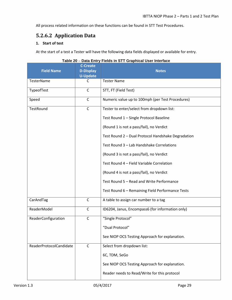
IBTTA NIOP Phase 2 – Parts 1 and 2 Test Plan
Version 1.3 05/4/2017 Page 29
All process related information on these functions can be found in STT Test Procedures.
5.2.6.2 Application Data 1. Start of test
At the start of a test a Tester will have the following data fields displayed or available for entry.
Table 20 – Data Entry Fields in STT Graphical User Interface
Field Name C-Create D-Display U-Update
Notes
TesterName C Tester Name
TypeofTest C STT, FT (Field Test)
Speed C Numeric value up to 100mph (per Test Procedures)
TestRound C Tester to enter/select from dropdown list:
Test Round 1 – Single Protocol Baseline
(Round 1 is not a pass/fail), no Verdict
Test Round 2 – Dual Protocol Handshake Degradation
Test Round 3 – Lab Handshake Correlations
(Round 3 is not a pass/fail), no Verdict
Test Round 4 – Field Variable Correlation
(Round 4 is not a pass/fail), no Verdict
Test Round 5 – Read and Write Performance
Test Round 6 – Remaining Field Performance Tests
CarAndTag C A table to assign car number to a tag
ReaderModel C ID6204, Janus, Encompass6 (for information only)
ReaderConfiguration C “Single Protocol”
“Dual Protocol”
See NIOP OCS Testing Approach for explanation.
ReaderProtocolCandidate C Select from dropdown list:
6C, TDM, SeGo
See NIOP OCS Testing Approach for explanation.
Reader needs to Read/Write for this protocol
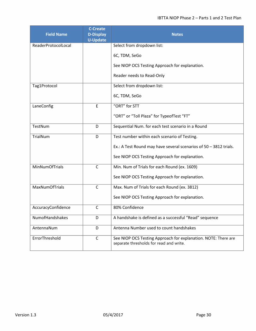
IBTTA NIOP Phase 2 – Parts 1 and 2 Test Plan
Version 1.3 05/4/2017 Page 30
Field Name C-Create D-Display U-Update
Notes
ReaderProtocolLocal Select from dropdown list:
6C, TDM, SeGo
See NIOP OCS Testing Approach for explanation.
Reader needs to Read-Only
Tag1Protocol Select from dropdown list:
6C, TDM, SeGo
LaneConfig E “ORT” for STT
“ORT” or “Toll Plaza” for TypeofTest “FT”
TestNum D Sequential Num. for each test scenario in a Round
TrialNum D Test number within each scenario of Testing.
Ex.: A Test Round may have several scenarios of 50 – 3812 trials.
See NIOP OCS Testing Approach for explanation.
MinNumOfTrials C Min. Num of Trials for each Round (ex. 1609)
See NIOP OCS Testing Approach for explanation.
MaxNumOfTrials C Max. Num of Trials for each Round (ex. 3812)
See NIOP OCS Testing Approach for explanation.
AccuracyConfidence C 80% Confidence
NumofHandshakes D A handshake is defined as a successful “Read” sequence
AntennaNum D Antenna Number used to count handshakes
ErrorThreshold C See NIOP OCS Testing Approach for explanation. NOTE: There are separate thresholds for read and write.
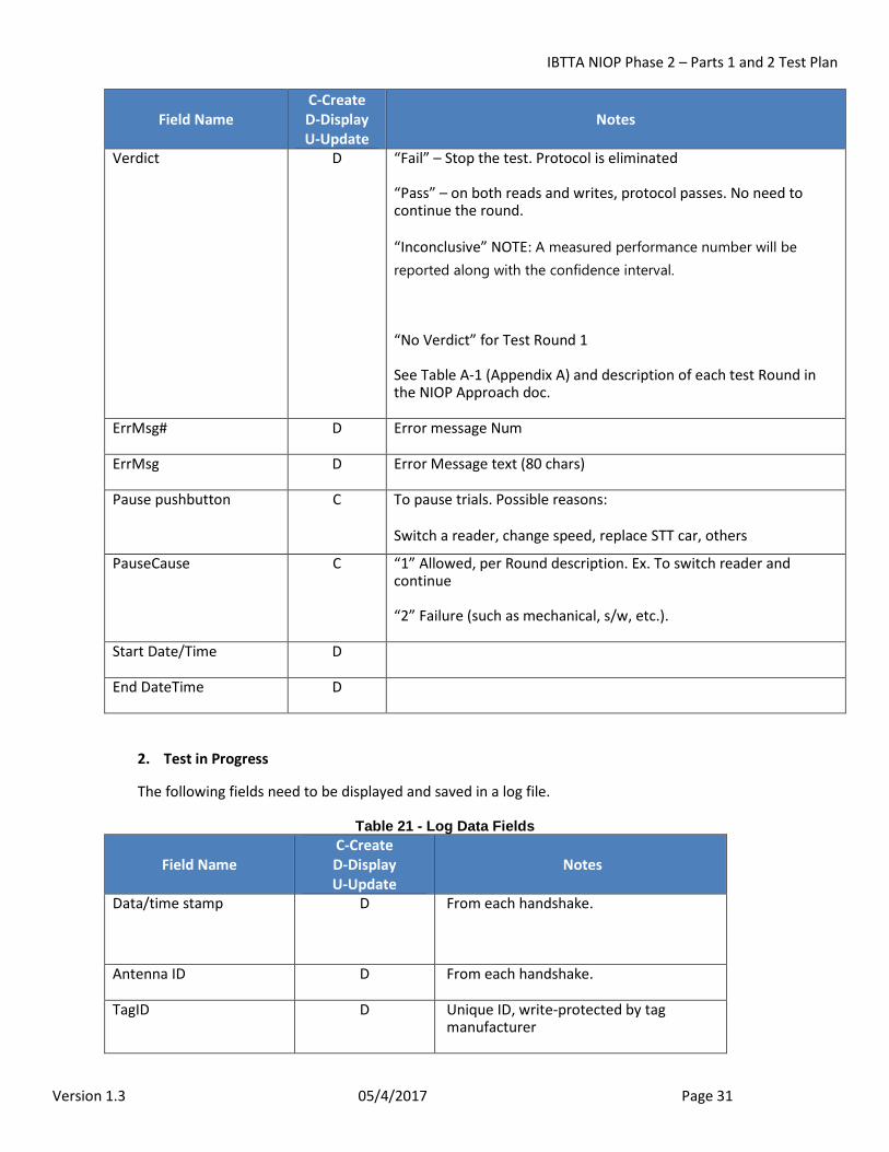
IBTTA NIOP Phase 2 – Parts 1 and 2 Test Plan
Version 1.3 05/4/2017 Page 31
Field Name C-Create D-Display U-Update
Notes
Verdict D “Fail” – Stop the test. Protocol is eliminated
“Pass” – on both reads and writes, protocol passes. No need to continue the round.
“Inconclusive” NOTE: A measured performance number will be reported along with the confidence interval.
“No Verdict” for Test Round 1
See Table A-1 (Appendix A) and description of each test Round in the NIOP Approach doc.
ErrMsg# D Error message Num
ErrMsg D Error Message text (80 chars)
Pause pushbutton C To pause trials. Possible reasons:
Switch a reader, change speed, replace STT car, others
PauseCause C “1” Allowed, per Round description. Ex. To switch reader and continue
“2” Failure (such as mechanical, s/w, etc.).
Start Date/Time D
End DateTime D
2. Test in Progress
The following fields need to be displayed and saved in a log file.
Table 21 - Log Data Fields
Field Name C-Create D-Display U-Update
Notes
Data/time stamp
D From each handshake.
Antenna ID D From each handshake.
TagID D Unique ID, write-protected by tag manufacturer
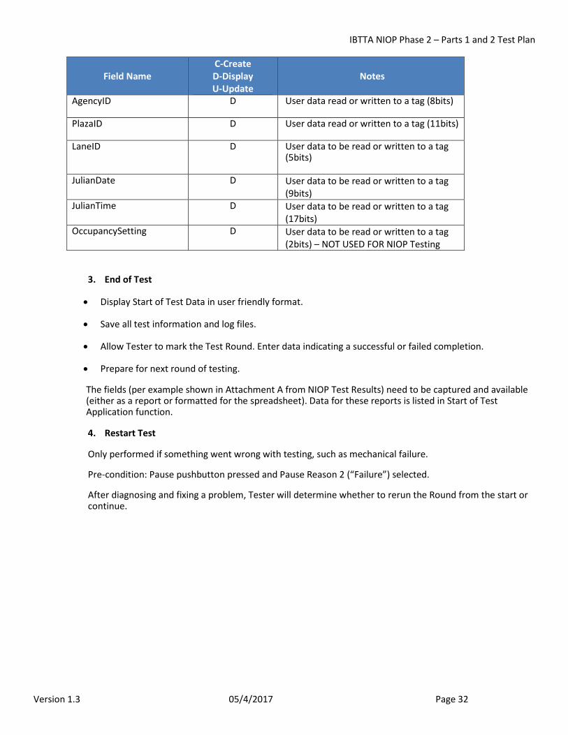
IBTTA NIOP Phase 2 – Parts 1 and 2 Test Plan
Version 1.3 05/4/2017 Page 32
Field Name C-Create D-Display U-Update
Notes
AgencyID D User data read or written to a tag (8bits)
PlazaID D User data read or written to a tag (11bits)
LaneID D User data to be read or written to a tag (5bits)
JulianDate D User data to be read or written to a tag (9bits)
JulianTime D User data to be read or written to a tag (17bits)
OccupancySetting D User data to be read or written to a tag (2bits) – NOT USED FOR NIOP Testing
3. End of Test
• Display Start of Test Data in user friendly format.
• Save all test information and log files.
• Allow Tester to mark the Test Round. Enter data indicating a successful or failed completion.
• Prepare for next round of testing.
The fields (per example shown in Attachment A from NIOP Test Results) need to be captured and available (either as a report or formatted for the spreadsheet). Data for these reports is listed in Start of Test Application function.
4. Restart Test
Only performed if something went wrong with testing, such as mechanical failure.
Pre-condition: Pause pushbutton pressed and Pause Reason 2 (“Failure”) selected.
After diagnosing and fixing a problem, Tester will determine whether to rerun the Round from the start or continue.
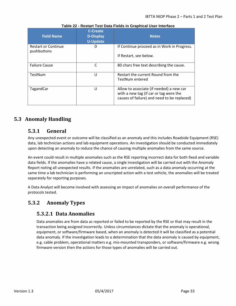
IBTTA NIOP Phase 2 – Parts 1 and 2 Test Plan
Version 1.3 05/4/2017 Page 33
Table 22 - Restart Test Data Fields in Graphical User Interface
Field Name C-Create D-Display U-Update
Notes
Restart or Continue pushbuttons
D If Continue proceed as in Work in Progress.
If Restart, see below.
Failure Cause C 80 chars free text describing the cause.
TestNum U Restart the current Round from the TestNum entered
TagandCar U Allow to associate (if needed) a new car with a new tag (if car or tag were the causes of failure) and need to be replaced)
5.3 Anomaly Handling
5.3.1 General Any unexpected event or outcome will be classified as an anomaly and this includes Roadside Equipment (RSE) data, lab technician actions and lab equipment operations. An investigation should be conducted immediately upon detecting an anomaly to reduce the chance of causing multiple anomalies from the same source.
An event could result in multiple anomalies such as the RSE reporting incorrect data for both fixed and variable data fields. If the anomalies have a related cause, a single investigation will be carried out with the Anomaly Report noting all unexpected results. If the anomalies are unrelated, such as a data anomaly occurring at the same time a lab technician is performing an unscripted action with a test vehicle, the anomalies will be treated separately for reporting purposes.
A Data Analyst will become involved with assessing an impact of anomalies on overall performance of the protocols tested.
5.3.2 Anomaly Types
5.3.2.1 Data Anomalies Data anomalies are from data as reported or failed to be reported by the RSE or that may result in the transaction being assigned incorrectly. Unless circumstances dictate that the anomaly is operational, equipment, or software/firmware based, when an anomaly is detected it will be classified as a potential data anomaly. If the investigation leads to a determination that the data anomaly is caused by equipment, e.g. cable problem, operational matters e.g. mis-mounted transponders, or software/firmware e.g. wrong firmware version then the actions for those types of anomalies will be carried out.
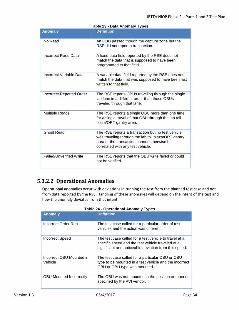
IBTTA NIOP Phase 2 – Parts 1 and 2 Test Plan
Version 1.3 05/4/2017 Page 34
Table 23 - Data Anomaly Types Anomaly Definition
No Read An OBU passed though the capture zone but the RSE did not report a transaction.
Incorrect Fixed Data A fixed data field reported by the RSE does not match the data that is supposed to have been programmed to that field.
Incorrect Variable Data A variable data field reported by the RSE does not match the data that was supposed to have been last written to that field.
Incorrect Reported Order The RSE reports OBUs traveling through the single lab lane in a different order than those OBUs traveled through that lane.
Multiple Reads The RSE reports a single OBU more than one time for a single travel of that OBU through the lab toll plaza/ORT gantry area.
Ghost Read The RSE reports a transaction but no test vehicle was traveling through the lab toll plaza/ORT gantry area or the transaction cannot otherwise be correlated with any test vehicle.
Failed/Unverified Write The RSE reports that the OBU write failed or could not be verified.
5.3.2.2 Operational Anomalies Operational anomalies occur with deviations in running the test from the planned test case and not from data reported by the RSE. Handling of these anomalies will depend on the intent of the test and how the anomaly deviates from that intent.
Table 24 - Operational Anomaly Types Anomaly Definition
Incorrect Order Run The test case called for a particular order of test vehicles and the actual was different.
Incorrect Speed The test case called for a test vehicle to travel at a specific speed and the test vehicle traveled at a significant and noticeable deviation from this speed.
Incorrect OBU Mounted in Vehicle
The test case called for a particular OBU or OBU type to be mounted in a test vehicle and the incorrect OBU or OBU type was mounted.
OBU Mounted Incorrectly The OBU was not mounted in the position or manner specified by the AVI vendor.
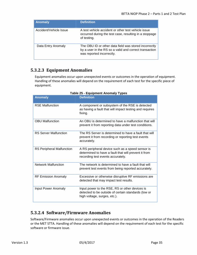
IBTTA NIOP Phase 2 – Parts 1 and 2 Test Plan
Version 1.3 05/4/2017 Page 35
Anomaly Definition
Accident/Vehicle Issue A test vehicle accident or other test vehicle issue occurred during the test case, resulting in a stoppage of testing.
Data Entry Anomaly The OBU ID or other data field was stored incorrectly by a user in the RS so a valid and correct transaction was reported incorrectly.
5.3.2.3 Equipment Anomalies Equipment anomalies occur upon unexpected events or outcomes in the operation of equipment. Handling of these anomalies will depend on the requirement of each test for the specific piece of equipment.
Table 25 - Equipment Anomaly Types Anomaly Definition
RSE Malfunction A component or subsystem of the RSE is detected as having a fault that will impact testing and requires fixing.
OBU Malfunction An OBU is determined to have a malfunction that will prevent it from reporting data under test conditions.
RS Server Malfunction The RS Server is determined to have a fault that will prevent it from recording or reporting test events accurately.
RS Peripheral Malfunction A RS peripheral device such as a speed sensor is determined to have a fault that will prevent it from recording test events accurately.
Network Malfunction The network is determined to have a fault that will prevent test events from being reported accurately.
RF Emission Anomaly Excessive or otherwise disruptive RF emissions are detected that may impact test results.
Input Power Anomaly Input power to the RSE, RS or other devices is detected to be outside of certain standards (low or high voltage, surges, etc.).
5.3.2.4 Software/Firmware Anomalies Software/Firmware anomalies occur upon unexpected events or outcomes in the operation of the Readers or the MET STTA. Handling of these anomalies will depend on the requirement of each test for the specific software or firmware issue.
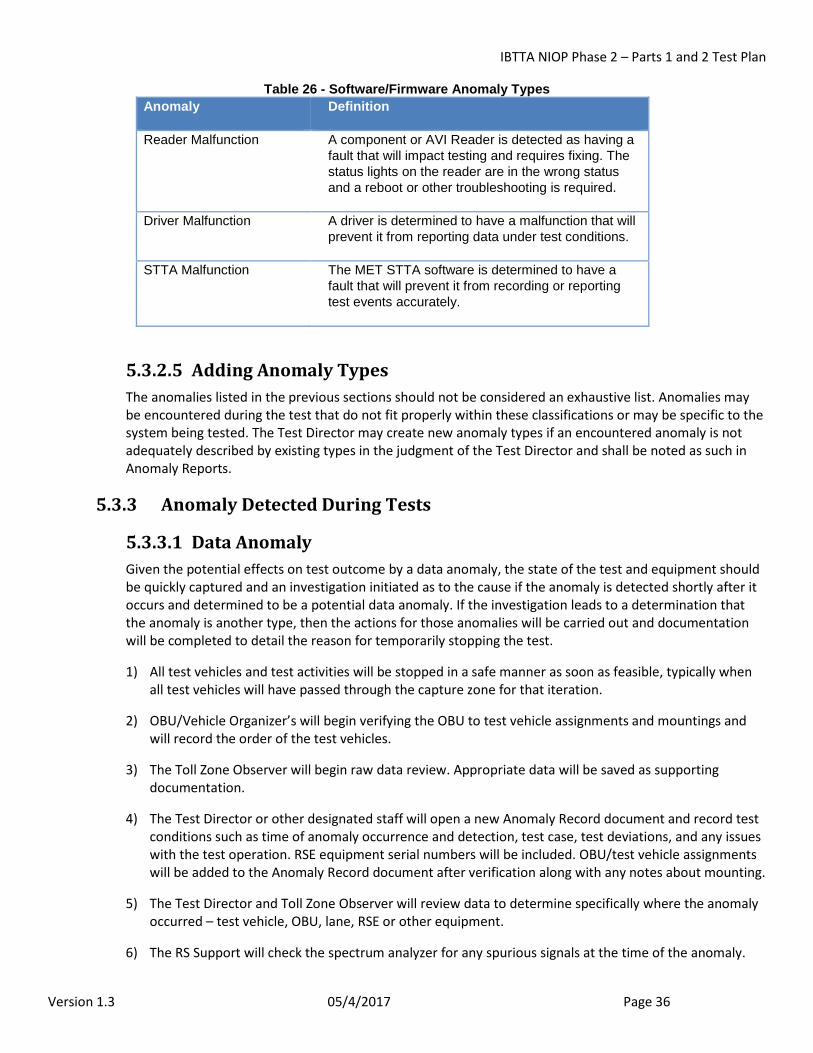
IBTTA NIOP Phase 2 – Parts 1 and 2 Test Plan
Version 1.3 05/4/2017 Page 36
Table 26 - Software/Firmware Anomaly Types Anomaly Definition
Reader Malfunction A component or AVI Reader is detected as having a fault that will impact testing and requires fixing. The status lights on the reader are in the wrong status and a reboot or other troubleshooting is required.
Driver Malfunction A driver is determined to have a malfunction that will prevent it from reporting data under test conditions.
STTA Malfunction The MET STTA software is determined to have a fault that will prevent it from recording or reporting test events accurately.
5.3.2.5 Adding Anomaly Types The anomalies listed in the previous sections should not be considered an exhaustive list. Anomalies may be encountered during the test that do not fit properly within these classifications or may be specific to the system being tested. The Test Director may create new anomaly types if an encountered anomaly is not adequately described by existing types in the judgment of the Test Director and shall be noted as such in Anomaly Reports.
5.3.3 Anomaly Detected During Tests
5.3.3.1 Data Anomaly Given the potential effects on test outcome by a data anomaly, the state of the test and equipment should be quickly captured and an investigation initiated as to the cause if the anomaly is detected shortly after it occurs and determined to be a potential data anomaly. If the investigation leads to a determination that the anomaly is another type, then the actions for those anomalies will be carried out and documentation will be completed to detail the reason for temporarily stopping the test.
1) All test vehicles and test activities will be stopped in a safe manner as soon as feasible, typically when all test vehicles will have passed through the capture zone for that iteration.
2) OBU/Vehicle Organizer’s will begin verifying the OBU to test vehicle assignments and mountings and will record the order of the test vehicles.
3) The Toll Zone Observer will begin raw data review. Appropriate data will be saved as supporting documentation.
4) The Test Director or other designated staff will open a new Anomaly Record document and record test conditions such as time of anomaly occurrence and detection, test case, test deviations, and any issues with the test operation. RSE equipment serial numbers will be included. OBU/test vehicle assignments will be added to the Anomaly Record document after verification along with any notes about mounting.
5) The Test Director and Toll Zone Observer will review data to determine specifically where the anomaly occurred – test vehicle, OBU, lane, RSE or other equipment.
6) The RS Support will check the spectrum analyzer for any spurious signals at the time of the anomaly.
IBTTA NIOP Phase 2 – Parts 1 and 2 Test Plan
Version 1.3 05/4/2017 Page 37
7) The RS Support and other staff will verify that the Data Collection and other test equipment operated correctly. This may include checking OBU data content and the RSE.
8) The Test Director will direct the OBU/Test Vehicles Organizers to retrieve any OBUs that may be involved in the anomaly. The OBU/Test Vehicles Organizers will run the OBUs through the OBU Tester and the results will be recorded in the Anomaly Report. If the OBU Tester reports the OBU as having failed, the OBU will be removed from testing and replaced with an OBU from the spare inventory. If the anomaly is determined to be caused by failure of the OBU, the anomaly will be counted as a failure in performance calculations.
9) Once the general source of the anomaly is understood, the Test Director will draft plans to proceed based on the nature of the anomaly, time needed to further research the anomaly and upcoming test cases. This may include leaving it to later analysis by off-site Data Analysts and continuing with the test.
10) Any notes taken during the test by staff will be collected for later scanning.
11) The Test Director will inform the OmniAir Team of the anomaly and discuss plans to proceed. Plans will depend on the type of anomaly and may include running different test cases while the anomaly is researched or changing the equipment used.
12) The OmniAir Team will provide input on potential courses of action and approve any plan submitted by the Test Director.
13) The Test Director will brief staff on how testing will proceed and what cases will be done and OBU/Test Vehicles Organizers will then brief the lab technicians.
14) Resume testing, if appropriate.
15) Off-site Data Analysts will begin reviewing data to verify if the initial investigation is accurate. They will also prepare the official Anomaly Report package.
16) Off-site Data Analysts will inform the Test Director of their conclusions and if they differ from the initial investigation.
17) The Test Director will review the Anomaly Report and incorporate it into the final Test Report.
5.3.3.2 Operational Anomaly These cases do not require the test to be suspended as the anomaly is not due to the equipment under test. The Test Director will have more leeway to handle the anomaly based on the nature of the anomaly and the test case. The OmniAir Team will be informed of the anomaly and handling but this may just be through the Daily Summary report.
The Test Director will make the following decisions upon detection of an operational anomaly:
1) Order the lab technicians of the test vehicles to take appropriate action such as pausing the test (pausing test software) and stopping the test vehicles wherever they are at in a safe manner, stopping them in a safe manner once the entire platoon has gone through the capture zone, having the test vehicles slow down but continue to prepare for the next iteration or taking no action at all. This may depend on if there are safety issues or if the Test Director needs more time to create a course of action.
2) Determine if the iteration or the entire test case needs to be re-run or if it can continue without interruption. For example, an OBU may be in the wrong test vehicle but if this is not critical to the test,
IBTTA NIOP Phase 2 – Parts 1 and 2 Test Plan
Version 1.3 05/4/2017 Page 38
the case may continue uninterrupted. If it is a key part such as the test vehicle needing to be run at a new speed, then the iteration may be re-run.
3) Determine how to prevent future occurrences. This may include informing the lab technician of the action that should have occurred, increasing time between iterations to ensure that the test vehicles are in the correct order or replacing an OBU with the proper one for the test case.
4) Decide if a lab technician should be replaced for the rest of the case if they may not be capable of performing their assignment in a safe and correct manner.
Test records will be annotated to note the anomaly. Documentation to be saved regarding the anomaly will include test case, circumstances of the anomaly (what was supposed to happen, what did happen, who was involved), data files, course of action after the anomaly and reasons for the course of action.
The Test Director will submit the anomaly records and actions taken to the OmniAir Team. The OmniAir Team will be informed of the anomaly on the same day that the anomaly is detected.
5.3.3.3 Equipment Anomaly These anomalies are the most problematic as they could cause extended delays to testing if replacement and recalibration is required. They may also occur when tests are not being conducted. Anomalies detected during a test may also be obvious equipment faults such as a failed camera or may be discovered while investigating another issue such as what is initially considered a No Read anomaly being caused by a defective network switch. For those anomalies that are clearly an equipment anomaly upon detection, the following actions will be taken:
1) The Test Director will have the test vehicles stop at a convenient point in a safe manner.
2) The Test Director and RS Support (or OBU/Test Vehicles Organizers for OBU anomalies) will check the equipment to verify the source of the fault.
3) The Toll Zone Observer will review the data to determine which transactions may have been affected by the anomaly while also saving copies of video and data files for review. Off-site Data Analysts may also perform this task, albeit with some delay.
4) The Test Director will develop a course of action considering the following issues:
• What is the anomaly affecting? A Temporary RF Emission Anomaly may have no effect on the outcome of the test case so the Test Director may continue the test and merely note the anomaly in the test record.
• What parts or actions are needed to prevent future occurrences of the anomaly and how long will it take?
• Can the test continue in some fashion, perhaps by modifying the scenario to avoid things affected by the anomaly?
• Can test events be accurately recorded?
• If the test can continue in some fashion, which test cases should the OmniAir Team consider rerunning?
5) The Test Director will inform the OmniAir Team of the anomaly and discuss plans to proceed. The discussion will address issues including when testing should resume, whether any transactions should
IBTTA NIOP Phase 2 – Parts 1 and 2 Test Plan
Version 1.3 05/4/2017 Page 39
be rerun and whether the AVI vendor will be required to repair, recalibrate, or replace the equipment. Plans will depend on the type of anomaly and effect on previous test cases. The OmniAir Team will provide input on potential courses of action and approve any plans submitted by the Test Director. Such plans may be contingent upon information gathered in the steps below.
6) The RS Support will complete an Equipment Anomaly Report on the equipment anomaly to include serial number of the equipment, circumstances of the anomaly and affected test transactions.
7) The Test Director will instruct the off-site Data Analysts to review previous data to determine if the equipment anomaly may have affected the data.
8) The Test Director will send the Equipment Anomaly Report to the OmniAir Team.
9) The Test Director will carry out the course of action as directed by the OmniAir Team.
5.3.4 Anomaly Detected During Post-Test Analysis
5.3.4.1 General As soon as possible, post-test analysis will be conducted off-site on the data collected from testing to determine if any anomalies were not detected during testing. Upon detection of an anomaly from the off-site review of collected data, the following procedures will be applied.
5.3.4.2 Data Anomaly In this case, the analysts must rely solely on recorded and saved data to investigate the anomaly. Like the real-time detection case, the Test Engineer may determine that the anomaly is of a different type and in such case; they will carry out the appropriate anomaly handling procedures.
1) The Test Engineer will inform the Test Director that a potential anomaly has been detected.
2) The Test Engineer will begin raw data review. Appropriate data will be saved as supporting documentation.
3) The Test Engineer will review images of the OBU mountings to verify that all OBUs were mounted correctly and to the best of their ability, verify that the test vehicle-OBU assignment data is correct.
4) The Test Engineer will open a new Anomaly Record document and record test conditions such as time of anomaly, test case, test deviations, and any issues with the test operation using available data. Available RSE equipment serial numbers will be included. OBU/test vehicle assignments will be added to the Anomaly Record document after verification along with any notes about mounting. Lab technician assignments will be added if available.
5) The Test Engineer will review data to determine specifically where the anomaly occurred – test vehicle, OBU, lane, RSE or other equipment.
6) The Test Engineer check the spectrum analyzer records for any spurious signals at the time of the anomaly.
7) The Test Engineer will check any available logs to confirm that the RS and other test equipment operated correctly.
8) Once the anomaly’s source has been isolated, the Test Engineer will inform the Test Director of the anomaly source.
IBTTA NIOP Phase 2 – Parts 1 and 2 Test Plan
Version 1.3 05/4/2017 Page 40
9) The Test Director will determine if any test cases for the day may need to be modified and develop plans to proceed.
10) The Test Director will inform the OmniAir Team of the anomaly and if there will be any need to modify upcoming test cases.
11) The OmniAir Team will provide input on potential courses of action and approve any plans submitted by the Test Director. Such plans may be contingent upon information gathered in the steps below.
12) The Test Director will inform the Test Staff if any changes are needed to upcoming test cases.
13) The Test Engineer will prepare the official Anomaly Report package.
14) The Test Director will review the Anomaly Report and include in the final Test Report.
5.3.4.3 Operational Anomaly There are fewer actions that need to be taken in this case as the anomaly is not one that is caused by equipment under test. The major decision for the OmniAir Team is if there will be a need to rerun any test cases. The general steps for handling this will be:
1) The Test Engineer will review the script and the actual actions based on raw data to ensure that an operational anomaly has been properly identified.
2) The Test Engineer will annotate the test record to note the anomaly. Appropriate documentation will be saved.
3) The Test Engineer will inform the Test Director.
4) The Test Director will review the anomaly and develop a course of action such as rerunning the test case, possibly only for a subset of the iterations or just accepting the data if the anomaly had no significant impact and is unrelated to the purpose of the test.
5) The Test Director will inform the OmniAir Team of the anomaly on the same day that the anomaly is detected and of subsequent actions taken.
6) The Test Engineer will prepare the official Anomaly Report package.
7) The Test Director will review the Anomaly Report and include in the final Test Report.
8) The OmniAir Team will determine if action is needed beyond what the Test Director has done.
5.3.4.4 Equipment Anomaly The concern in this case is that the equipment may still be malfunctioning and it could affect testing. Any anomalies that have occurred before the malfunction took place and afterwards will also have to be reinvestigated to verify if the equipment played a part in the anomaly.
1) The Test Engineer will annotate the test record to note the anomaly. Appropriate documentation will be saved.
2) The Test Engineer will inform the Test Director.
3) The Test Director will determine if testing should be halted at a convenient point to check the equipment or if it can be done while testing continues.
IBTTA NIOP Phase 2 – Parts 1 and 2 Test Plan
Version 1.3 05/4/2017 Page 41
4) The Test Director will notify the OmniAir Team of the anomaly detection and whether testing will be halted to check the equipment.
5) The Test Director and RS Support (or OBU/Test Vehicles Organizers for OBU anomalies) will check the equipment to verify the source of the fault and if not currently malfunctioning, the likelihood of it occurring again.
6) The Test Engineer will review anomalies or other test issues that have occurred before and since the initial malfunction to determine if they may also have been affected. Depending on the nature of the anomaly, transactions may have to be reviewed.
7) The Test Director will develop a course of action considering the following issues:
• What may the anomaly affect if it reoccurs?
• What is the likelihood of the anomaly reoccurring? If it is not likely to reoccur or cannot be predicted, such as for Temporary RF Emission Anomalies, the Test Director may continue the test as normal.
• What parts or actions are needed to fix the anomaly and how long will it take?
• Can test events be accurately recorded?
• If the test can continue in some fashion, which test cases should the OmniAir Team consider rerunning?
8) The Test Director will inform OmniAir Team of the anomaly and discuss plans to proceed. The discussion will address issues including when testing should resume, whether any transactions should be rerun and whether the AVI vendor will be required to repair, recalibrate, or replace the equipment. Plans will depend on the type of anomaly and may include running different test cases while the anomaly is researched or changing the equipment used.
9) The OmniAir Team will provide input on potential courses of action and approve any plans submitted by the Test Director. Such plans may be contingent upon information gathered in the steps below.
10) The RS Support will write an Equipment Anomaly Report on the equipment anomaly to include serial number of the equipment if available, circumstances of the anomaly and affected test transactions with the help of the Test Engineer.
11) The Test Director will send the Equipment Anomaly Report to the OmniAir Team.
12) The Test Director will carry out the course of action as directed by the OmniAir Team.
5.3.4.5 Anomaly is Detected During Non-Test Time Equipment checks will be done before and after testing each day. There is the possibility of an equipment anomaly being detected, in which case the following actions will be done:
1) Test staff will record the equipment serial number and nature of the anomaly.
2) If possible, test staff will recheck the equipment to see if the anomaly is repeated.
3) The Test Director or other designated staff will open a new Equipment Anomaly Report document and record the anomaly, the check that was being performed and recent equipment usage. Equipment serial numbers will be included.
IBTTA NIOP Phase 2 – Parts 1 and 2 Test Plan
Version 1.3 05/4/2017 Page 42
4) The RS Support will check the spectrum analyzer for any spurious signals at the time of the anomaly.
5) The RS Support and other staff will verify that related equipment such as the Data Collection and other test equipment are operating correctly and not the source of the anomaly. This may include checking OBU data content and the RSE.
6) Once the anomaly’s source has been isolated, the Test Director will determine how to proceed based on the nature of the anomaly, time needed to fix the problem and upcoming test cases. Possible courses of action include:
• If no reason for the anomaly is found, proceeding with no adjustments;
• If OBU is reported by the OBU Tester to be malfunctioning, remove the OBU from testing and replace it with an OBU from spare inventory;
• If the RSE is malfunctioning, replace the malfunctioning equipment. This may require AVI vendor involvement as determined by the OmniAir Team;
• If data collection equipment malfunctioning, replace equipment if adjustments cannot be made;
• Note that if RSE or data collection equipment is repaired or replaced, some equipment may need to be calibrated.
7) All notes taken during the test by staff will be collected for later scanning.
8) The Test Director shall inform OmniAir Team of the anomaly and discuss potential courses of action.
9) The OmniAir Team will provide input on potential courses of action and approve a final plan.
10) Off-site Data Analysts will begin reviewing data to verify if initial conclusions are accurate. They will also prepare the official Equipment Anomaly Report package.
11) Off-site Data Analysts will also review previous data to check if the data may have been affected by the equipment anomaly.
12) Off-site Data Analysts will inform the Test Director of their conclusions and if they differ from the initial conclusions, the Test Director will decide on how to proceed.
13) The Test Director will review the Equipment Anomaly Report and include in the final Test Report.
5.3.5 Anomaly Tracking Upon creation, anomalies will be given an ID using the following codes:
<AVI Vendor>_<Scenario>_<Sequence Number>
Where:
• AVI Vendor is ‘3M’ for 3M, ‘KP’ for Kapsch or ‘TC’ for TransCore and represents the AVI reader under test;
• Scenario is a two-character ID with the first character representing the Test Objective (1 or 2) and the second character representing the Scenario # from Table 7, Table 8, Table 9, Table 10, or Table 11 that indicates RSE/OBU combination; and
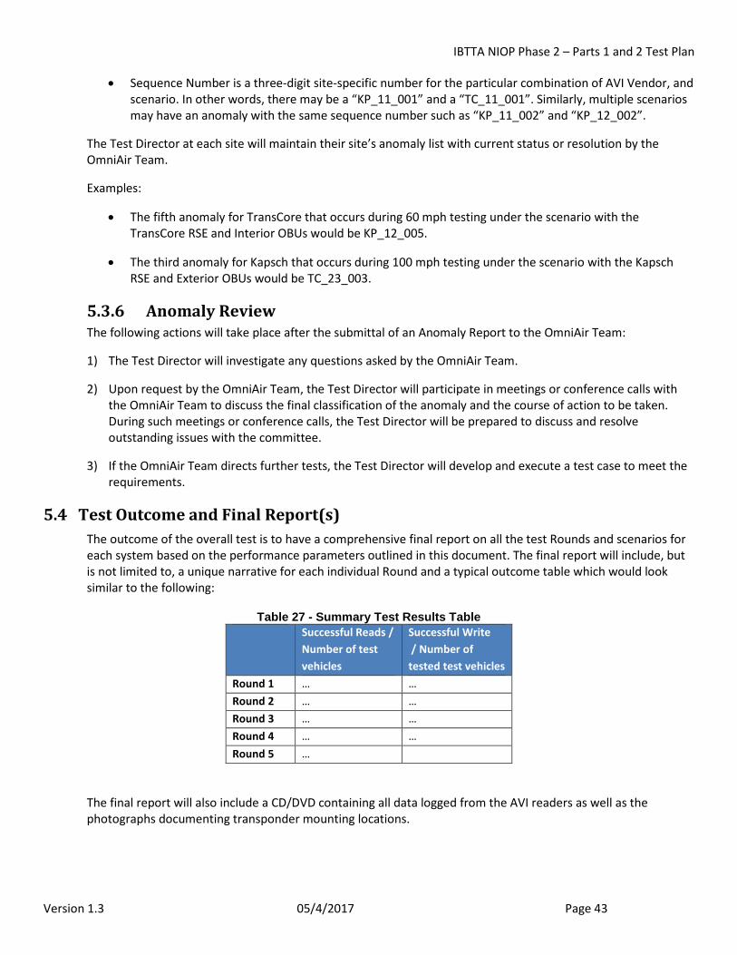
IBTTA NIOP Phase 2 – Parts 1 and 2 Test Plan
Version 1.3 05/4/2017 Page 43
• Sequence Number is a three-digit site-specific number for the particular combination of AVI Vendor, and scenario. In other words, there may be a “KP_11_001” and a “TC_11_001”. Similarly, multiple scenarios may have an anomaly with the same sequence number such as “KP_11_002” and “KP_12_002”.
The Test Director at each site will maintain their site’s anomaly list with current status or resolution by the OmniAir Team.
Examples:
• The fifth anomaly for TransCore that occurs during 60 mph testing under the scenario with the TransCore RSE and Interior OBUs would be KP_12_005.
• The third anomaly for Kapsch that occurs during 100 mph testing under the scenario with the Kapsch RSE and Exterior OBUs would be TC_23_003.
5.3.6 Anomaly Review The following actions will take place after the submittal of an Anomaly Report to the OmniAir Team:
1) The Test Director will investigate any questions asked by the OmniAir Team.
2) Upon request by the OmniAir Team, the Test Director will participate in meetings or conference calls with the OmniAir Team to discuss the final classification of the anomaly and the course of action to be taken. During such meetings or conference calls, the Test Director will be prepared to discuss and resolve outstanding issues with the committee.
3) If the OmniAir Team directs further tests, the Test Director will develop and execute a test case to meet the requirements.
5.4 Test Outcome and Final Report(s) The outcome of the overall test is to have a comprehensive final report on all the test Rounds and scenarios for each system based on the performance parameters outlined in this document. The final report will include, but is not limited to, a unique narrative for each individual Round and a typical outcome table which would look similar to the following:
Table 27 - Summary Test Results Table Successful Reads /
Number of test vehicles
Successful Write / Number of tested test vehicles
Round 1 … … Round 2 … … Round 3 … … Round 4 … … Round 5 …
The final report will also include a CD/DVD containing all data logged from the AVI readers as well as the photographs documenting transponder mounting locations.
IBTTA NIOP Phase 2 – Parts 1 and 2 Test Plan
Version 1.3 05/4/2017 Page 44
5.5 Limitations to Test Plan All parties involved in this undertaking understand that there are limitations to the current test plan based on available resources. Some of these limitations that exist within the scope of this testing, acknowledged by the OmniAir Team are as follows:
Vehicle Speed
The OmniAir Team will operate test vehicles at 60,80 and 100 mph, typical highway speeds and extreme speed in the lab. The vehicles driven in Round 4 field testing will be operated at 60 and 80 mph.
Environmental Conditions
The testing will not include adverse environmental conditions such as inclement weather, heavy rain, snow, temperature, humidity etc., as the testing described in this plan is in the lab and any limited Environmental testing will be done separate from the trials at speed in a controlled lab environment test chamber.
Externally Introduced Interference
The testing will not include any other potential interference than already existing in the environment. The external interference which will not be specifically tested are the following allowed under FCC regulations “cell phones, on-board license transmitters, airports, military, navy, etc.” within immediate proximity. Vendors will conduct spectrum surveys to ensure there are no RF interference that can compromise the test.
Non-RFID Components of the Toll Collection System
This testing will not verify other components of the toll collection system such as the automatic vehicle classification system, violation enforcement system and traffic and revenue messages as well as financial transaction systems.
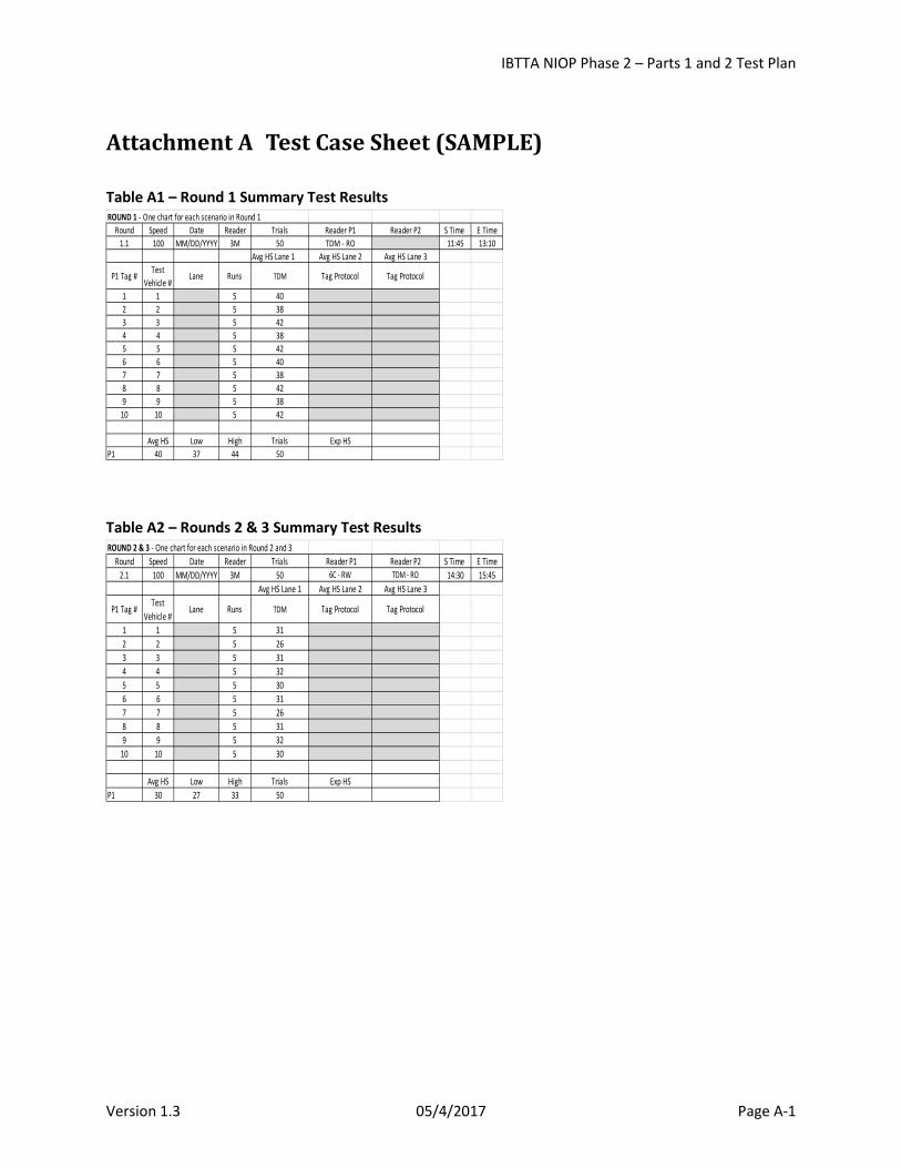
IBTTA NIOP Phase 2 – Parts 1 and 2 Test Plan
Version 1.3 05/4/2017 Page A-1
Attachment A Test Case Sheet (SAMPLE) Table A1 – Round 1 Summary Test Results
Table A2 – Rounds 2 & 3 Summary Test Results
ROUND 1 - One chart for each scenario in Round 1Round Speed Date Reader Trials Reader P1 Reader P2 S Time E Time
1.1 100 MM/DD/YYYY 3M 50 TDM - RO 11:45 13:10Avg HS Lane 1 Avg HS Lane 2 Avg HS Lane 3
P1 Tag # Test Vehicle #
Lane Runs TDM Tag Protocol Tag Protocol
1 1 5 402 2 5 383 3 5 424 4 5 385 5 5 426 6 5 407 7 5 388 8 5 429 9 5 38
10 10 5 42
Avg HS Low High Trials Exp HSP1 40 37 44 50
ROUND 2 & 3 - One chart for each scenario in Round 2 and 3Round Speed Date Reader Trials Reader P1 Reader P2 S Time E Time
2.1 100 MM/DD/YYYY 3M 50 6C - RW TDM - RO 14:30 15:45Avg HS Lane 1 Avg HS Lane 2 Avg HS Lane 3
P1 Tag # Test Vehicle #
Lane Runs TDM Tag Protocol Tag Protocol
1 1 5 312 2 5 263 3 5 314 4 5 325 5 5 306 6 5 317 7 5 268 8 5 319 9 5 32
10 10 5 30
Avg HS Low High Trials Exp HSP1 30 27 33 50
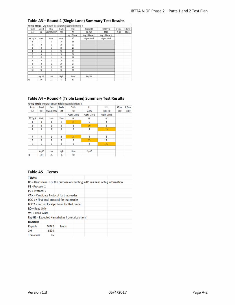
IBTTA NIOP Phase 2 – Parts 1 and 2 Test Plan
Version 1.3 05/4/2017 Page A-2
Table A3 – Round 4 (Single Lane) Summary Test Results
Table A4 – Round 4 (Triple Lane) Summary Test Results
Table A5 – Terms
ROUND 4 Single - One chart for each single lane scenario in Round 4Round Speed Date Reader Trials Reader P1 Reader P2 S Time E Time
4.1 60 MM/DD/YYYY 3M 50 6C-RW TDM 9:00 11:05Avg HS Lane 1 Avg HS Lane 2 Avg HS Lane 3
P1 Tag # Car # Lane Runs 6C Tag Protocol Tag Protocol1 1 1 10 312 2 1 10 303 3 1 10 274 4 1 10 285 5 1 10 346 6 1 10 317 7 1 10 308 8 1 10 279 9 1 10 28
10 10 1 10 34
Avg HS Low High Runs Exp HSP1 30 27 33 50

IBTTA NIOP Phase 2 – Parts 1 and 2 Test Plan
Version 1.3 05/4/2017 Page B-1
Attachment B STT Test Procedures
IBTTA NIOP Phase 2 – Parts 1 and 2 Test Plan
Version 1.3 05/4/2017 Page B-2
STT Simulated Toll Testing
NIOP Electronic Toll Collection Protocol
Lab Test Procedures
April 25, 2016
Draft Version
IBTTA NIOP Phase 2 – Parts 1 and 2 Test Plan
Version 1.3 05/4/2017 Page B-3
Table of Contents
1 Scope .................................................................................................................................................. B-4 2 Reference Documents ........................................................................................................................ B-4 3 Background ........................................................................................................................................ B-4 4 Disclaimer ........................................................................................................................................... B-4 5 Site Overview ..................................................................................................................................... B-4
5.1 Test Track ................................................................................................................................... B-4 5.2 Tolling Equipment Layout .......................................................................................................... B-4 5.3 Site Safety and Security ............................................................................................................. B-5 5.4 Personnel Safety ........................................................................................................................ B-5
6 Personnel ........................................................................................................................................... B-5 6.1 Test Engineer ............................................................................................................................. B-5 6.2 Track Inspection ......................................................................................................................... B-5 6.3 Test Vehicle Inspection .............................................................................................................. B-5 6.4 Test Results Validation ............................................................................................................... B-5 6.5 Supporting Personnel ................................................................................................................. B-6 6.6 RFID Tags .................................................................................................................................... B-6 6.7 RFID Reader ................................................................................................................................ B-6 6.8 RFID Cable .................................................................................................................................. B-6
7 Definitions .......................................................................................................................................... B-7 8 Optimized STT Plan ............................................................................................................................ B-8
8.1 Representative Lap .................................................................................................................... B-8 8.2 Test Round 1 – Setup ................................................................................................................. B-9 8.3 Test Round 2 – Setup ................................................................................................................. B-9 8.4 Test Round 3 – Setup ............................................................................................................... B-10 8.5 Test Round 5 – Setup ............................................................................................................... B-10
9 MET STT Application ........................................................................................................................ B-11 9.1 Functions Summary ................................................................................................................. B-11 9.2 Considerations ......................................................................................................................... B-13
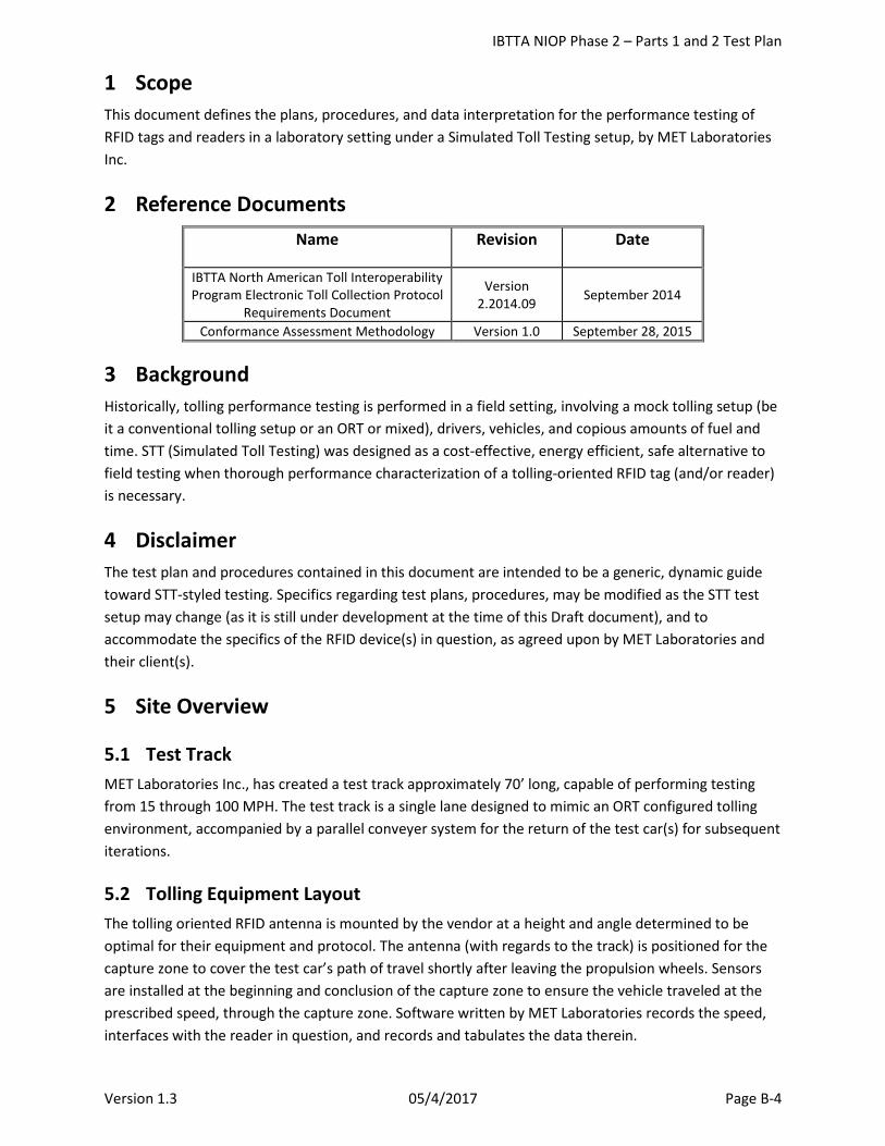
IBTTA NIOP Phase 2 – Parts 1 and 2 Test Plan
Version 1.3 05/4/2017 Page B-4
1 Scope This document defines the plans, procedures, and data interpretation for the performance testing of RFID tags and readers in a laboratory setting under a Simulated Toll Testing setup, by MET Laboratories Inc.
2 Reference Documents Name Revision Date
IBTTA North American Toll Interoperability Program Electronic Toll Collection Protocol
Requirements Document
Version 2.2014.09 September 2014
Conformance Assessment Methodology Version 1.0 September 28, 2015
3 Background Historically, tolling performance testing is performed in a field setting, involving a mock tolling setup (be it a conventional tolling setup or an ORT or mixed), drivers, vehicles, and copious amounts of fuel and time. STT (Simulated Toll Testing) was designed as a cost-effective, energy efficient, safe alternative to field testing when thorough performance characterization of a tolling-oriented RFID tag (and/or reader) is necessary.
4 Disclaimer The test plan and procedures contained in this document are intended to be a generic, dynamic guide toward STT-styled testing. Specifics regarding test plans, procedures, may be modified as the STT test setup may change (as it is still under development at the time of this Draft document), and to accommodate the specifics of the RFID device(s) in question, as agreed upon by MET Laboratories and their client(s).
5 Site Overview
5.1 Test Track MET Laboratories Inc., has created a test track approximately 70’ long, capable of performing testing from 15 through 100 MPH. The test track is a single lane designed to mimic an ORT configured tolling environment, accompanied by a parallel conveyer system for the return of the test car(s) for subsequent iterations.
5.2 Tolling Equipment Layout The tolling oriented RFID antenna is mounted by the vendor at a height and angle determined to be optimal for their equipment and protocol. The antenna (with regards to the track) is positioned for the capture zone to cover the test car’s path of travel shortly after leaving the propulsion wheels. Sensors are installed at the beginning and conclusion of the capture zone to ensure the vehicle traveled at the prescribed speed, through the capture zone. Software written by MET Laboratories records the speed, interfaces with the reader in question, and records and tabulates the data therein.
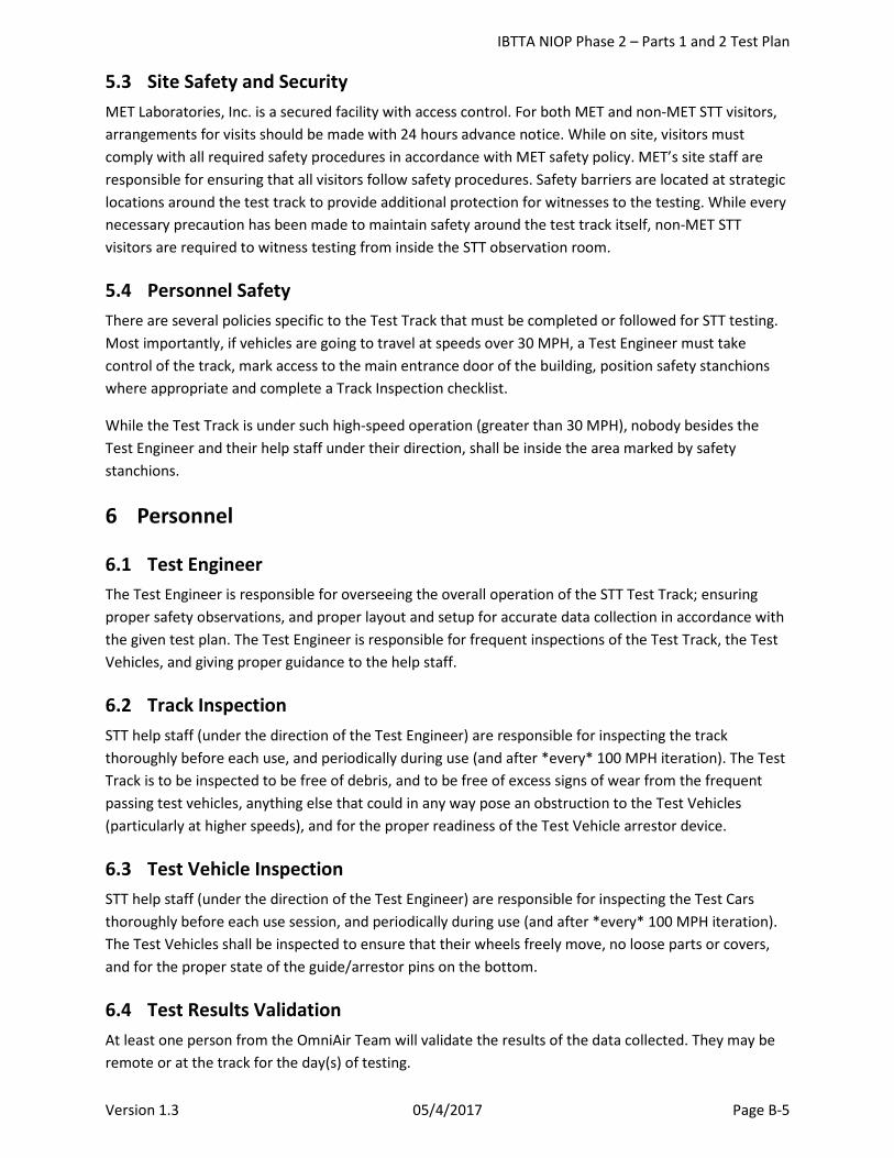
IBTTA NIOP Phase 2 – Parts 1 and 2 Test Plan
Version 1.3 05/4/2017 Page B-5
5.3 Site Safety and Security MET Laboratories, Inc. is a secured facility with access control. For both MET and non-MET STT visitors, arrangements for visits should be made with 24 hours advance notice. While on site, visitors must comply with all required safety procedures in accordance with MET safety policy. MET’s site staff are responsible for ensuring that all visitors follow safety procedures. Safety barriers are located at strategic locations around the test track to provide additional protection for witnesses to the testing. While every necessary precaution has been made to maintain safety around the test track itself, non-MET STT visitors are required to witness testing from inside the STT observation room.
5.4 Personnel Safety There are several policies specific to the Test Track that must be completed or followed for STT testing. Most importantly, if vehicles are going to travel at speeds over 30 MPH, a Test Engineer must take control of the track, mark access to the main entrance door of the building, position safety stanchions where appropriate and complete a Track Inspection checklist.
While the Test Track is under such high-speed operation (greater than 30 MPH), nobody besides the Test Engineer and their help staff under their direction, shall be inside the area marked by safety stanchions.
6 Personnel
6.1 Test Engineer The Test Engineer is responsible for overseeing the overall operation of the STT Test Track; ensuring proper safety observations, and proper layout and setup for accurate data collection in accordance with the given test plan. The Test Engineer is responsible for frequent inspections of the Test Track, the Test Vehicles, and giving proper guidance to the help staff.
6.2 Track Inspection STT help staff (under the direction of the Test Engineer) are responsible for inspecting the track thoroughly before each use, and periodically during use (and after *every* 100 MPH iteration). The Test Track is to be inspected to be free of debris, and to be free of excess signs of wear from the frequent passing test vehicles, anything else that could in any way pose an obstruction to the Test Vehicles (particularly at higher speeds), and for the proper readiness of the Test Vehicle arrestor device.
6.3 Test Vehicle Inspection STT help staff (under the direction of the Test Engineer) are responsible for inspecting the Test Cars thoroughly before each use session, and periodically during use (and after *every* 100 MPH iteration). The Test Vehicles shall be inspected to ensure that their wheels freely move, no loose parts or covers, and for the proper state of the guide/arrestor pins on the bottom.
6.4 Test Results Validation At least one person from the OmniAir Team will validate the results of the data collected. They may be remote or at the track for the day(s) of testing.
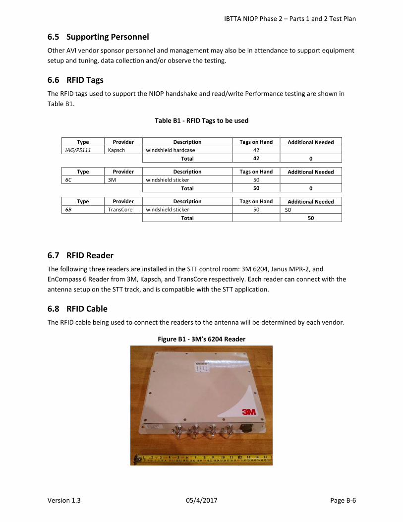
IBTTA NIOP Phase 2 – Parts 1 and 2 Test Plan
Version 1.3 05/4/2017 Page B-6
6.5 Supporting Personnel Other AVI vendor sponsor personnel and management may also be in attendance to support equipment setup and tuning, data collection and/or observe the testing.
6.6 RFID Tags The RFID tags used to support the NIOP handshake and read/write Performance testing are shown in Table B1.
Table B1 - RFID Tags to be used
6.7 RFID Reader The following three readers are installed in the STT control room: 3M 6204, Janus MPR-2, and EnCompass 6 Reader from 3M, Kapsch, and TransCore respectively. Each reader can connect with the antenna setup on the STT track, and is compatible with the STT application.
6.8 RFID Cable The RFID cable being used to connect the readers to the antenna will be determined by each vendor.
Figure B1 - 3M’s 6204 Reader
Type Provider Description Tags on Hand Additional Needed IAG/PS111 Kapsch windshield hardcase 42
Total 42 0 Type Provider Description Tags on Hand Additional Needed
6C 3M windshield sticker 50
Total 50 0 Type Provider Description Tags on Hand Additional Needed
6B TransCore windshield sticker 50 50
Total 50
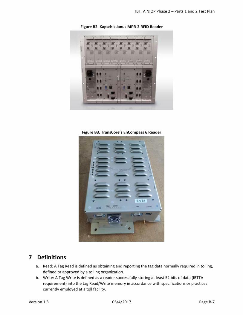
IBTTA NIOP Phase 2 – Parts 1 and 2 Test Plan
Version 1.3 05/4/2017 Page B-7
Figure B2. Kapsch’s Janus MPR-2 RFID Reader
Figure B3. TransCore’s EnCompass 6 Reader
7 Definitions a. Read: A Tag Read is defined as obtaining and reporting the tag data normally required in tolling,
defined or approved by a tolling organization. b. Write: A Tag Write is defined as a reader successfully storing at least 52 bits of data (IBTTA
requirement) into the tag Read/Write memory in accordance with specifications or practices currently employed at a toll facility.
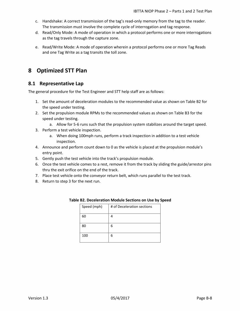
IBTTA NIOP Phase 2 – Parts 1 and 2 Test Plan
Version 1.3 05/4/2017 Page B-8
c. Handshake: A correct transmission of the tag’s read-only memory from the tag to the reader. The transmission must involve the complete cycle of interrogation and tag response.
d. Read/Only Mode: A mode of operation in which a protocol performs one or more interrogations as the tag travels through the capture zone.
e. Read/Write Mode: A mode of operation wherein a protocol performs one or more Tag Reads and one Tag Write as a tag transits the toll zone.
8 Optimized STT Plan
8.1 Representative Lap The general procedure for the Test Engineer and STT help staff are as follows:
1. Set the amount of deceleration modules to the recommended value as shown on Table B2 for the speed under testing.
2. Set the propulsion module RPMs to the recommended values as shown on Table B3 for the speed under testing.
a. Allow for 5-6 runs such that the propulsion system stabilizes around the target speed. 3. Perform a test vehicle inspection.
a. When doing 100mph runs, perform a track inspection in addition to a test vehicle inspection.
4. Announce and perform count down to 0 as the vehicle is placed at the propulsion module’s entry point.
5. Gently push the test vehicle into the track’s propulsion module. 6. Once the test vehicle comes to a rest, remove it from the track by sliding the guide/arrestor pins
thru the exit orifice on the end of the track. 7. Place test vehicle onto the conveyor return belt, which runs parallel to the test track. 8. Return to step 3 for the next run.
Table B2. Deceleration Module Sections on Use by Speed Speed (mph) # of Deceleration sections
60 4
80 6
100 6
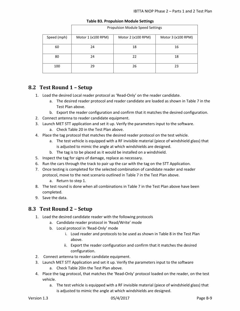
IBTTA NIOP Phase 2 – Parts 1 and 2 Test Plan
Version 1.3 05/4/2017 Page B-9
Table B3. Propulsion Module Settings Propulsion Module Speed Settings
Speed (mph) Motor 1 (x100 RPM) Motor 2 (x100 RPM) Motor 3 (x100 RPM)
60 24 18 16
80 24 22 18
100 29 26 23
8.2 Test Round 1 – Setup 1. Load the desired Local reader protocol as ‘Read-Only’ on the reader candidate.
a. The desired reader protocol and reader candidate are loaded as shown in Table 7 in the Test Plan above.
b. Export the reader configuration and confirm that it matches the desired configuration. 2. Connect antenna to reader candidate equipment. 3. Launch MET STT application and set it up. Verify the parameters input to the software.
a. Check Table 20 in the Test Plan above. 4. Place the tag protocol that matches the desired reader protocol on the test vehicle.
a. The test vehicle is equipped with a RF invisible material (piece of windshield glass) that is adjusted to mimic the angle at which windshields are designed.
b. The tag is to be placed as it would be installed on a windshield. 5. Inspect the tag for signs of damage, replace as necessary. 6. Run the cars through the track to pair up the car with the tag on the STT Application. 7. Once testing is completed for the selected combination of candidate reader and reader
protocol, move to the next scenario outlined in Table 7 in the Test Plan above. a. Return to step 1.
8. The test round is done when all combinations in Table 7 in the Test Plan above have been completed.
9. Save the data.
8.3 Test Round 2 – Setup 1. Load the desired candidate reader with the following protocols
a. Candidate reader protocol in ‘Read/Write’ mode b. Local protocol in ‘Read-Only’ mode
i. Load reader and protocols to be used as shown in Table 8 in the Test Plan above.
ii. Export the reader configuration and confirm that it matches the desired configuration.
2. Connect antenna to reader candidate equipment. 3. Launch MET STT Application and set it up. Verify the parameters input to the software
a. Check Table 20in the Test Plan above. 4. Place the tag protocol, that matches the ‘Read-Only’ protocol loaded on the reader, on the test
vehicle. a. The test vehicle is equipped with a RF invisible material (piece of windshield glass) that
is adjusted to mimic the angle at which windshields are designed.
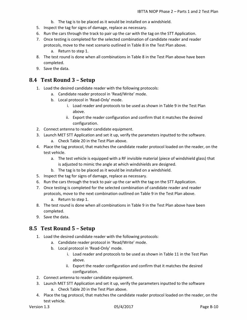
IBTTA NIOP Phase 2 – Parts 1 and 2 Test Plan
Version 1.3 05/4/2017 Page B-10
b. The tag is to be placed as it would be installed on a windshield. 5. Inspect the tag for signs of damage, replace as necessary. 6. Run the cars through the track to pair up the car with the tag on the STT Application. 7. Once testing is completed for the selected combination of candidate reader and reader
protocols, move to the next scenario outlined in Table 8 in the Test Plan above. a. Return to step 1.
8. The test round is done when all combinations in Table 8 in the Test Plan above have been completed.
9. Save the data.
8.4 Test Round 3 – Setup 1. Load the desired candidate reader with the following protocols:
a. Candidate reader protocol in ‘Read/Write’ mode. b. Local protocol in ‘Read-Only’ mode.
i. Load reader and protocols to be used as shown in Table 9 in the Test Plan above.
ii. Export the reader configuration and confirm that it matches the desired configuration.
2. Connect antenna to reader candidate equipment. 3. Launch MET STT Application and set it up, verify the parameters inputted to the software.
a. Check Table 20 in the Test Plan above. 4. Place the tag protocol, that matches the candidate reader protocol loaded on the reader, on the
test vehicle. a. The test vehicle is equipped with a RF invisible material (piece of windshield glass) that
is adjusted to mimic the angle at which windshields are designed. b. The tag is to be placed as it would be installed on a windshield.
5. Inspect the tag for signs of damage, replace as necessary. 6. Run the cars through the track to pair up the car with the tag on the STT Application. 7. Once testing is completed for the selected combination of candidate reader and reader
protocols, move to the next combination outlined on Table 9 in the Test Plan above. a. Return to step 1.
8. The test round is done when all combinations in Table 9 in the Test Plan above have been completed.
9. Save the data.
8.5 Test Round 5 – Setup 1. Load the desired candidate reader with the following protocols:
a. Candidate reader protocol in ‘Read/Write’ mode. b. Local protocol in ‘Read-Only’ mode.
i. Load reader and protocols to be used as shown in Table 11 in the Test Plan above.
ii. Export the reader configuration and confirm that it matches the desired configuration.
2. Connect antenna to reader candidate equipment. 3. Launch MET STT Application and set it up, verify the parameters inputted to the software
a. Check Table 20 in the Test Plan above. 4. Place the tag protocol, that matches the candidate reader protocol loaded on the reader, on the
test vehicle.
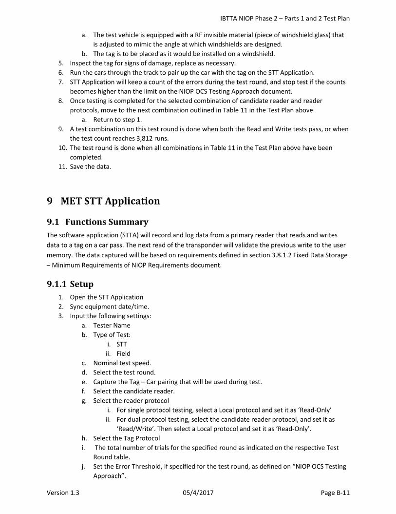
IBTTA NIOP Phase 2 – Parts 1 and 2 Test Plan
Version 1.3 05/4/2017 Page B-11
a. The test vehicle is equipped with a RF invisible material (piece of windshield glass) that is adjusted to mimic the angle at which windshields are designed.
b. The tag is to be placed as it would be installed on a windshield. 5. Inspect the tag for signs of damage, replace as necessary. 6. Run the cars through the track to pair up the car with the tag on the STT Application. 7. STT Application will keep a count of the errors during the test round, and stop test if the counts
becomes higher than the limit on the NIOP OCS Testing Approach document. 8. Once testing is completed for the selected combination of candidate reader and reader
protocols, move to the next combination outlined in Table 11 in the Test Plan above. a. Return to step 1.
9. A test combination on this test round is done when both the Read and Write tests pass, or when the test count reaches 3,812 runs.
10. The test round is done when all combinations in Table 11 in the Test Plan above have been completed.
11. Save the data.
9 MET STT Application
9.1 Functions Summary The software application (STTA) will record and log data from a primary reader that reads and writes data to a tag on a car pass. The next read of the transponder will validate the previous write to the user memory. The data captured will be based on requirements defined in section 3.8.1.2 Fixed Data Storage – Minimum Requirements of NIOP Requirements document.
9.1.1 Setup 1. Open the STT Application 2. Sync equipment date/time. 3. Input the following settings:
a. Tester Name b. Type of Test:
i. STT ii. Field
c. Nominal test speed. d. Select the test round. e. Capture the Tag – Car pairing that will be used during test. f. Select the candidate reader. g. Select the reader protocol
i. For single protocol testing, select a Local protocol and set it as ‘Read-Only’ ii. For dual protocol testing, select the candidate reader protocol, and set it as
‘Read/Write’. Then select a Local protocol and set it as ‘Read-Only’. h. Select the Tag Protocol i. The total number of trials for the specified round as indicated on the respective Test
Round table. j. Set the Error Threshold, if specified for the test round, as defined on “NIOP OCS Testing
Approach”.
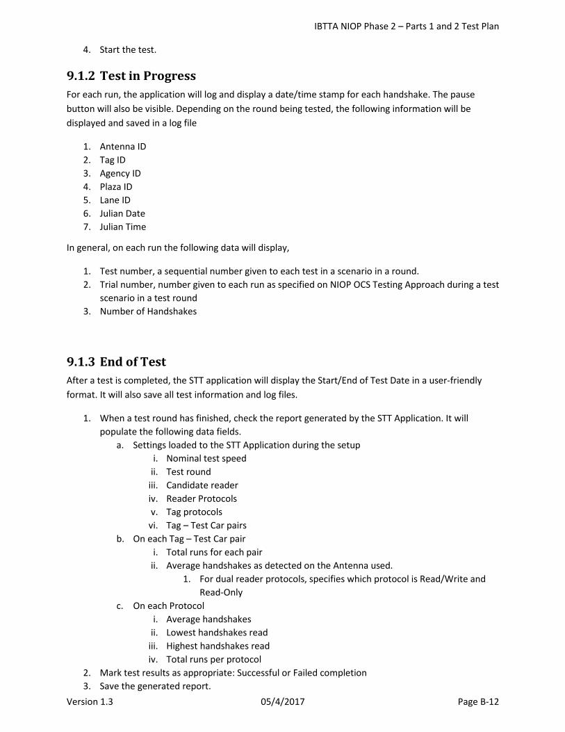
IBTTA NIOP Phase 2 – Parts 1 and 2 Test Plan
Version 1.3 05/4/2017 Page B-12
4. Start the test.
9.1.2 Test in Progress For each run, the application will log and display a date/time stamp for each handshake. The pause button will also be visible. Depending on the round being tested, the following information will be displayed and saved in a log file
1. Antenna ID 2. Tag ID 3. Agency ID 4. Plaza ID 5. Lane ID 6. Julian Date 7. Julian Time
In general, on each run the following data will display,
1. Test number, a sequential number given to each test in a scenario in a round. 2. Trial number, number given to each run as specified on NIOP OCS Testing Approach during a test
scenario in a test round 3. Number of Handshakes
9.1.3 End of Test After a test is completed, the STT application will display the Start/End of Test Date in a user-friendly format. It will also save all test information and log files.
1. When a test round has finished, check the report generated by the STT Application. It will populate the following data fields.
a. Settings loaded to the STT Application during the setup i. Nominal test speed
ii. Test round iii. Candidate reader iv. Reader Protocols v. Tag protocols
vi. Tag – Test Car pairs b. On each Tag – Test Car pair
i. Total runs for each pair ii. Average handshakes as detected on the Antenna used.
1. For dual reader protocols, specifies which protocol is Read/Write and Read-Only
c. On each Protocol i. Average handshakes
ii. Lowest handshakes read iii. Highest handshakes read iv. Total runs per protocol
2. Mark test results as appropriate: Successful or Failed completion 3. Save the generated report.
IBTTA NIOP Phase 2 – Parts 1 and 2 Test Plan
Version 1.3 05/4/2017 Page B-13
4. Confirm log name matches naming convention. 5. Run the setup for the next round of testing.
9.1.4 Restart Test Only to be performed if an anomaly defined in the OmniAir NIOP Test Plan, requiring action from the Test Engineer, occurred during a run.
1. To access the Restart Menu/Options during testing: a. Press the Pause button b. Select option ‘2’ (“Failure”).
2. Describe the failure cause in the text box 3. Input the run number on which the test will restart from.
a. Depending on the type of failure, the restart can continue the current test sequence, or restart prior to the point the failure occurred.
b. The Test Engineer must decide the course of action, taking into account the recommendations given on the “Considerations” section.
4. If needed, input a new Tag – Car pair association. 5. Press the Restart Button.
9.2 Considerations
9.2.1 Test Vehicle Damaged As the damage is spotted, the test engineer will replace the broken/damaged car with a new car from the lab spare pool. The Test Engineer will perform a vehicle inspection on the car. The tag-car pair that links to the damaged car will be taken out of the testing loop, but its data will remain on the log. The new tag-car pair will be added to the STT application testing loop. On the STT Application, hit the pause button, select option’2’ (“Failure”). Describe the cause of failure in the text box.
During single protocol testing:
• If the handshake reading is considerably lower or higher than previous runs, then restart the STT app from the previous run.
• If the test car had to be replaced, then associate the tag with the new test car and restart on current run.
• If the damage caused the tag to fall from its natural position, then readjust the tag and restart on previous run.
During dual protocol testing:
• If the equipment anomaly occurs after the Read/Write pass, then restart by repeating the Read/Write pass. It is done this way, so everything remains constant on a read-write-read run.
• If the test car had to be replaced after a completed read-write-read run, then associate the tag with the new test car and restart on current run.
• If the damage caused the tag to fall from its position, then restart prior to the read/write pass.
IBTTA NIOP Phase 2 – Parts 1 and 2 Test Plan
Version 1.3 05/4/2017 Page B-14
9.2.2 Long Breaks For breaks longer or equal to 10 minutes, recalibrate the RPMs on the propulsion module. Perform 5 to 6 runs prior to resuming testing to allow for the propulsion system to warm up and stabilize to the desired launch speed.
On STT Application, push the pause button, and resume as normal when ready.
9.2.3 Track Reconfiguration As the target speed is changed, the track setup will change to accommodate the propulsion and deceleration modules, so that the test vehicle reaches the target speed and comes to a stop in a safe manner at the end of the track. Perform a track inspection prior to resuming testing. Similar to long breaks, allow for 5 to 6 runs for the propulsion module to stabilize around the target speed, then resume testing.
9.2.4 Propulsion Module As the module warms up due to continuous testing, its launch speed progressively gets faster. When the launch speed starts to consistently approach the tolerance limit of +/-5% of the target speed, it will be necessary to lower the RPMs on the motors controlling the propulsion module. A pair of check runs will be performed in order to verify that the launch speed has changed to tolerable levels.
On the STT Application, press Pause and Resume when ready.
9.2.5 Deceleration Module As the test vehicle continues to make passes thru the track, the deceleration module’s stopping power degrades. When the Test Engineer considers that the test vehicle is no longer stopping in a safe manner at the end of the track, the deceleration module sections will be readjusted or replaced with another set.

IBTTA NIOP Phase 2 – Parts 1 and 2 Test Plan
Version 1.3 05/4/2017 Page C-1
Attachment C STT Field Test Procedures
IBTTA NIOP Phase 2 – Parts 1 and 2 Test Plan
Version 1.3 05/4/2017 Page C-2
Round 4 – NIOP Field Testing
NIOP Electronic Toll Collection Protocol
Field Test Procedures
April 28, 2017
Draft Version
IBTTA NIOP Phase 2 – Parts 1 and 2 Test Plan
Version 1.3 05/4/2017 Page C-3
Table of Contents
1 Scope .................................................................................................................................................. C-4 2 Site Safety and Security ..................................................................................................................... C-4 3 Supporting Personnel ......................................................................................................................... C-4
3.1 Test Director............................................................................................................................... C-4 3.2 Test Lead .................................................................................................................................... C-4 3.3 Vehicle Marshall ......................................................................................................................... C-4 3.4 Test Engineer ............................................................................................................................. C-4 3.5 Drivers ........................................................................................................................................ C-5
4 Equipment (field testing info) ............................................................................................................ C-5 4.1 RFID Antennas ............................................................................................................................ C-5 4.2 RFID Tags .................................................................................................................................... C-5 4.3 RFID Reader ................................................................................................................................ C-5 4.4 RFID Cable .................................................................................................................................. C-5 4.5 Vehicles ...................................................................................................................................... C-6 4.6 Other Infrastructure ................................................................................................................... C-6
5 Pre-test Preparation........................................................................................................................... C-6 5.1 Track Closure .............................................................................................................................. C-6 5.2 Track Inspection ......................................................................................................................... C-6 5.3 Vehicle Inspection ...................................................................................................................... C-6 5.4 Driver Training............................................................................................................................ C-6 5.5 Communication .......................................................................................................................... C-6
6 Preparing Vehicles and Tags .............................................................................................................. C-7 7 Suggested Schedule ........................................................................................................................... C-7 8 Daily Test Preparation ........................................................................................................................ C-8 9 Round 4 Test Procedures ................................................................................................................... C-8
9.1 Single Lane Runs ........................................................................................................................ C-8 9.2 Triple Lane Runs ......................................................................................................................... C-9
10 Data Validation................................................................................................................................... C-9 10.1 Collection of Data ....................................................................................................................... C-9
11 Error Handling .................................................................................................................................... C-9
IBTTA NIOP Phase 2 – Parts 1 and 2 Test Plan
Version 1.3 05/4/2017 Page C-4
1 Scope This document defines the test procedures for the performance testing of RFID tags and readers in an ORT field test environment. Testing will be conducted in one-lane and in three-lane scenarios.
Reference Documents
Name Revision Date
IBTTA North American Toll Interoperability Program Electronic Toll Collection Protocol
Requirements Document
Version 2.2014.09
September 2014
Conformance Assessment Methodology Version 1.0 September 28, 2015
2 Site Safety and Security OmniAir designated participant (IBI or MET Labs) will be responsible for site safety and security during the actual testing. A Test Lead will complete a Test Inspection Checklist prior to testing, to ensure that unauthorized personnel are not present on or near the test track, all track personnel wear safety vests, test drivers have attended a training session and that all access gates are closed during testing.
3 Supporting Personnel
3.1 Test Director The Test Director (an OmniAir designated representative) is responsible for the overall Round 4 testing. The Test Director is assisted by all supporting personnel and makes key decisions on the continuation or ending of test runs.
3.2 Test Lead The Test Lead is the primary interface with OmniAir personnel (TTI). He/she is in charge of the track and drivers during the testing. The Test Lead is responsible for the safety of everyone on the track and ensures that the proper procedures are followed, including closing off the track, making sure that the vehicles and track are inspected, directing drivers, and being the main point of contact with site security. The Test Lead communicates with the drivers and other test personnel via 2-way radios.
3.3 Vehicle Marshall The Vehicle Marshall is responsible for setting up a platoon (formation) of vehicles according to test scenarios, along with starting and stopping each trial.
3.4 Test Engineer The Test Engineer is responsible for overseeing the overall operation of the Field Test; ensuring proper safety observations, and proper layout and setup for accurate data collection in accordance with the given test plan.
Test Engineers will collect test data and record test results.
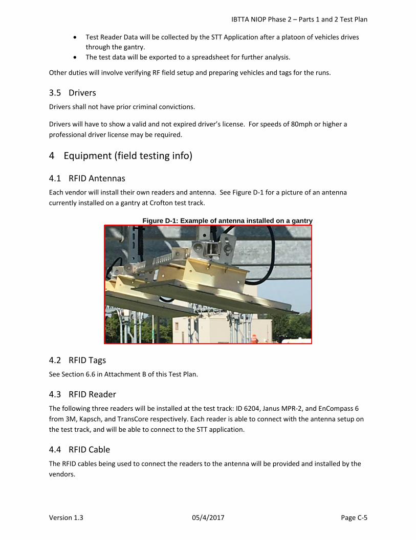
IBTTA NIOP Phase 2 – Parts 1 and 2 Test Plan
Version 1.3 05/4/2017 Page C-5
• Test Reader Data will be collected by the STT Application after a platoon of vehicles drives through the gantry.
• The test data will be exported to a spreadsheet for further analysis.
Other duties will involve verifying RF field setup and preparing vehicles and tags for the runs.
3.5 Drivers Drivers shall not have prior criminal convictions.
Drivers will have to show a valid and not expired driver’s license. For speeds of 80mph or higher a professional driver license may be required.
4 Equipment (field testing info)
4.1 RFID Antennas Each vendor will install their own readers and antenna. See Figure D-1 for a picture of an antenna currently installed on a gantry at Crofton test track.
Figure D-1: Example of antenna installed on a gantry
4.2 RFID Tags See Section 6.6 in Attachment B of this Test Plan.
4.3 RFID Reader The following three readers will be installed at the test track: ID 6204, Janus MPR-2, and EnCompass 6 from 3M, Kapsch, and TransCore respectively. Each reader is able to connect with the antenna setup on the test track, and will be able to connect to the STT application.
4.4 RFID Cable The RFID cables being used to connect the readers to the antenna will be provided and installed by the vendors.
IBTTA NIOP Phase 2 – Parts 1 and 2 Test Plan
Version 1.3 05/4/2017 Page C-6
4.5 Vehicles The OmniAir team will provide rental vehicles, drivers, will do the background check and provide personnel insurance.
A variety of vehicles will be used at 60mph and 80mph +/- 5% test speed. The vehicles will only include sedans. Each driver must complete a Vehicle Inspection checklist before the vehicle is allowed on the track. All vehicles will have a clearly visible number attached to the side of the vehicle.
4.6 Other Infrastructure Roadside cabinets contain additional equipment needed to support the tests, including power supplies and network switches. The readers are accessed over a private network for initial configuration and data collection.
5 Pre-test Preparation
5.1 Track Closure The Test Director confirms that main gates to the track are closed to prevent other vehicles from entering the track during testing.
5.2 Track Inspection The Test Director completes and signs the Track Inspection Checklist confirming that the track has been inspected and is clear of debris. Environmental conditions such as fog and standing water should be noted, which may affect safe driving speeds. The Track Inspection Checklist can be found on the Attachment G
5.3 Vehicle Inspection Drivers complete and sign the Vehicle Inspection Checklist for their assigned vehicle, which the Test Director also signs. Special attention should be given to vehicle brakes, oil level and tires. The Vehicle Inspection Checklist can be found in the Attachment H.
5.4 Driver Training Drivers will witness a demonstration of safety procedures and vehicle lineup, a test drive, and receive a pre-test briefing from the Test Director. Drivers will also take practice laps before any official testing takes place.
5.5 Communication Each driver will receive a 2-way radio for communication with the Test Director. It is important to keep the line clear so that instructions from the Test Director can be heard clearly. Drivers are not allowed to have cell phones on the track, and should limit the volume of the vehicle stereo radio to minimize potential distractions.
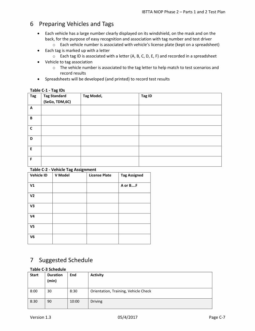
IBTTA NIOP Phase 2 – Parts 1 and 2 Test Plan
Version 1.3 05/4/2017 Page C-7
6 Preparing Vehicles and Tags • Each vehicle has a large number clearly displayed on its windshield, on the mask and on the
back, for the purpose of easy recognition and association with tag number and test driver o Each vehicle number is associated with vehicle’s license plate (kept on a spreadsheet)
• Each tag is marked up with a letter o Each tag ID is associated with a letter (A, B, C, D, E, F) and recorded in a spreadsheet
• Vehicle to tag association o The vehicle number is associated to the tag letter to help match to test scenarios and
record results • Spreadsheets will be developed (and printed) to record test results
Table C-1 - Tag IDs Tag Tag Standard
(SeGo, TDM,6C) Tag Model, Tag ID
A
B
C
D
E
F
Table C-2 - Vehicle Tag Assignment Vehicle ID V Model License Plate Tag Assigned
V1 A or B….F
V2
V3
V4
V5
V6
7 Suggested Schedule Table C-3 Schedule Start Duration
(min) End Activity
8:00 30 8:30 Orientation, Training, Vehicle Check
8:30 90 10:00 Driving
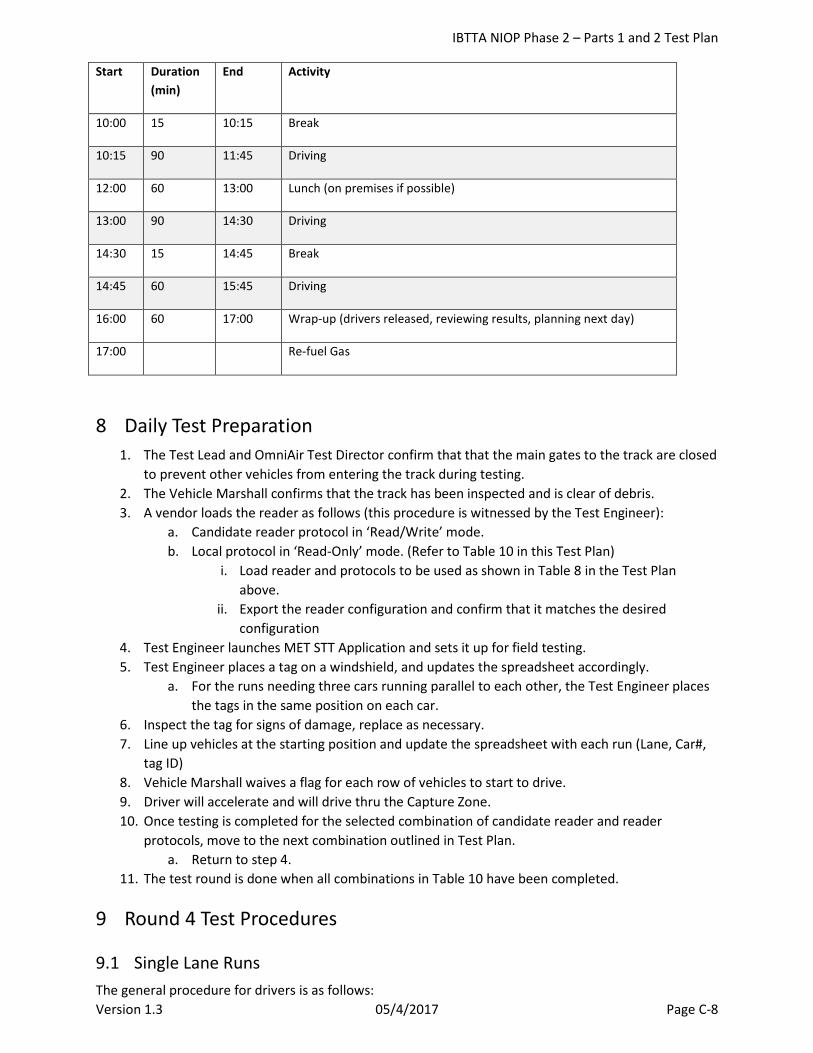
IBTTA NIOP Phase 2 – Parts 1 and 2 Test Plan
Version 1.3 05/4/2017 Page C-8
Start Duration (min)
End Activity
10:00 15 10:15 Break
10:15 90 11:45 Driving
12:00 60 13:00 Lunch (on premises if possible)
13:00 90 14:30 Driving
14:30 15 14:45 Break
14:45 60 15:45 Driving
16:00 60 17:00 Wrap-up (drivers released, reviewing results, planning next day)
17:00 Re-fuel Gas
8 Daily Test Preparation 1. The Test Lead and OmniAir Test Director confirm that that the main gates to the track are closed
to prevent other vehicles from entering the track during testing. 2. The Vehicle Marshall confirms that the track has been inspected and is clear of debris. 3. A vendor loads the reader as follows (this procedure is witnessed by the Test Engineer):
a. Candidate reader protocol in ‘Read/Write’ mode. b. Local protocol in ‘Read-Only’ mode. (Refer to Table 10 in this Test Plan)
i. Load reader and protocols to be used as shown in Table 8 in the Test Plan above.
ii. Export the reader configuration and confirm that it matches the desired configuration
4. Test Engineer launches MET STT Application and sets it up for field testing. 5. Test Engineer places a tag on a windshield, and updates the spreadsheet accordingly.
a. For the runs needing three cars running parallel to each other, the Test Engineer places the tags in the same position on each car.
6. Inspect the tag for signs of damage, replace as necessary. 7. Line up vehicles at the starting position and update the spreadsheet with each run (Lane, Car#,
tag ID) 8. Vehicle Marshall waives a flag for each row of vehicles to start to drive. 9. Driver will accelerate and will drive thru the Capture Zone. 10. Once testing is completed for the selected combination of candidate reader and reader
protocols, move to the next combination outlined in Test Plan. a. Return to step 4.
11. The test round is done when all combinations in Table 10 have been completed.
9 Round 4 Test Procedures
9.1 Single Lane Runs The general procedure for drivers is as follows:
IBTTA NIOP Phase 2 – Parts 1 and 2 Test Plan
Version 1.3 05/4/2017 Page C-9
1. Line up at the road leading to the Track’s entry point. 2. Wait until the Test Director confirms safe entry to the track. 3. Head towards the set of cones signaling the starting point. Perform a U-turn with the intent to align
with the cones. 3.1. Drivers will be told which lane to drive through at the beginning of the lap by the Test Director.
4. When the Test Director indicates it, accelerate thru the track aiming to reach 60mph or 80mph when entering the Capture Zone.
5. Use the rest of the track to safely slow down the vehicle. 6. Use the exit point to merge onto the road leading to the Track’s entry point.
6.1. Vehicles may be queuing for their next run, so drive at a safe speed i.e. 15mph. 7. Return to Step 1 to prepare for the next run.
9.2 Triple Lane Runs The general procedure for drivers is as follows:
1. Line up at the road leading to the Track’s entry point. 2. Wait until the Test Director confirms safe entry to the track. 3. Head towards the set of cones signaling the starting point. Perform a U-turn with the intent to align
with the cones. 3.1. Three cars will enter in a row, leading car will use the left lane, second car will use the middle
lane, and last car will use the right lane. 3.2. As the cars start aligning, the space for a U-turn reduces. Therefore, drive a little further down
the road to perform a safe turn. 4. When the Test Director indicates it, accelerate thru the track aiming to reach 60mph or 80mph
when entering the Capture Zone. 4.1. All three cars should enter the Capture Zone at the same time.
5. Use the rest of the track to safely slow down the vehicle. 6. Use the exit point to merge onto the road leading to the Track’s entry point.
6.1. First vehicle to exit the track should be the car driving on the left lane. Next, the car on the middle lane, and the car on the right lane exits last.
6.2. Vehicles may be queuing for their next run, so drive at a safe speed i.e. 15mph. 7. Return to Step 1 to prepare for the next run.
10 Data Validation
10.1 Collection of Data The data associated with the test runs will be collected by the MET software application, and exported to a spreadsheet for further analysis.
11 Error Handling See Details of Anomaly Handling in Section 5.3.
If errors are detected, they will be analyzed after each Pass of a platoon of vehicles.
Testing will stop to allow the cause to be discovered, analyzed, and corrected.

IBTTA NIOP Phase 2 – Parts 1 and 2 Test Plan
Version 1.3 05/4/2017 Page C-10
Test Director with inputs from Test Lead will make a decision on how to categorize this error and will make a decision to continue testing.

IBTTA NIOP Phase 2 – Parts 1 and 2 Test Plan
Version 1.3 05/4/2017 Page D-1
Attachment D NIOP Test Program Protocol Hypothesis Testing As described in the National Interoperability (NIOP) Test Program Test Planning document, Rounds 3 and 4 of the International Bridge and Tunnel Tolling Association’s (IBTTA) NIOP Test Program are intended to assess whether or not lab testing can act as a surrogate for field testing (and under which conditions) and which variables have a statistical impact on protocol performance. In order to make these evaluations, hypothesis testing and associated statistical analysis will be applied.
In Round 3 of testing, conducted in the lab environment, the intent is to establish a baseline of measured handshake data for the candidate protocols which will in turn be used in determining whether or not the lab can be used as a surrogate for field testing. During this baseline testing, each of the candidate protocols will be run through the track at designated speeds (60 mph, 80 mph, and 100 mph) and with each of the other candidate protocols being used in dual protocol mode. In other words, Protocol A will be tested with both Protocol B and Protocol C. To that end, there will be a total of 18 configurations conducted in this round of testing as noted below.
Table 28. Round 3 Testing Configurations Candidate
Reader Reader
Protocol 1 (i) Reader
Protocol 2 (j) Tag
Protocol Speed (k)
A A B A 60 A A B A 80 A A B A 100 A A C A 60 A A C A 80 A A C A 100 B B A B 60 B B A B 80 B B A B 100 B B C B 60 B B C B 80 B B C B 100 C C A C 60 C C A C 80 C C A C 100 C C B C 60 C C B C 80 C C B C 100
At the conclusion of this round of testing, the raw data collected will include the total number of handshakes (needs defined) observed during each run, the speed at which the vehicle passed through the capture zone, and the time spent in the capture zone (the zone size will be predefined and so this time can be estimated based on the speed at which the vehicle enters the zone). This information will be used to calculate the relative number of handshakes based on speed, to allow for an assessment of the

IBTTA NIOP Phase 2 – Parts 1 and 2 Test Plan
Version 1.3 05/4/2017 Page D-2
impact of speed. Also, calculated will be the average number of handshakes observed under each configuration, to be used in Round 4 testing.
Testing in Round 3 will be conducted using a test for proportions, with those proportions based on the amount of time a vehicle spends in the capture zone (based on its speed, as described above). As each run is performed, its handshake proportion will be calculated as:
𝐻𝐻𝑖𝑖𝑖𝑖𝑖𝑖𝑖𝑖 =𝑁𝑁𝑁𝑁𝑁𝑁𝑁𝑁𝑁𝑁𝑁𝑁 𝑜𝑜𝑜𝑜 𝐻𝐻𝐻𝐻𝐻𝐻𝐻𝐻𝐻𝐻ℎ𝐻𝐻𝑎𝑎𝑁𝑁𝐻𝐻 𝑂𝑂𝑁𝑁𝐻𝐻𝑁𝑁𝑁𝑁𝑂𝑂𝑁𝑁𝐻𝐻
𝑇𝑇𝑇𝑇𝑁𝑁𝑁𝑁 𝑇𝑇𝐻𝐻 𝑅𝑅𝑁𝑁𝐻𝐻𝐻𝐻 𝑍𝑍𝑜𝑜𝐻𝐻𝑁𝑁, 𝑤𝑤ℎ𝑁𝑁𝑁𝑁𝑁𝑁
• Hijkn is the handshake proportion for o Reader Protocol 1 = i, i ε {A, B, C}, o Reader Protocol 2 = j, j ε {A, B, C} and j ≠ i, o Speed = k, k ε {60 mph, 80 mph, 100 mph}, and o Run number = n, n = 1..N
For each configuration defined in Table 28, the average proportion will be calculated as:
𝑝𝑝𝑖𝑖𝑖𝑖𝑖𝑖 = �𝐻𝐻𝑖𝑖𝑖𝑖𝑖𝑖𝑖𝑖𝑁𝑁
, ∀ 𝑇𝑇, 𝑗𝑗,𝑎𝑎, 𝑤𝑤ℎ𝑁𝑁𝑁𝑁𝑁𝑁 𝑁𝑁
𝑖𝑖=1
• pijk is the average handshake proportion for the designated configuration • N = number of runs for the designated configuration (note that N is intended to be the same for
all configurations)
Next, the average proportions will be compared across speeds to determine whether or not the handshake proportion is consistent across the speeds under evaluation. In reality, the null hypothesis (H0) in this case is pij1 = pij2 = pij3, and the alternative hypothesis (HA) is that at least one pijk is different from the others (for each i and j), so ideally the Chi Square test would be used to make the assessment. However, due to the manner in which the proportions (pijk) are being calculated, it is impossible to calculate the expected frequencies needed to perform this test (this “proportion” does not include the binomial result typically used in performing the Chi Square test). Instead, the speed comparisons will be conducted through a series of three two-proportion z-tests, for each i and j pair, where
• H01: pij1 = pij2 and HA1: pij1 ≠ pij2 • H02: pij1 = pij3 and HA2: pij1 ≠ pij3 • H03: pij2 = pij3 and HA3: pij2 ≠ pij3
Those two-proportion z tests will be analyzed using the standard formulae:
𝑧𝑧 =(𝑝𝑝1 − 𝑝𝑝2)
�𝑝𝑝(1 − 𝑝𝑝) � 1𝐻𝐻1
+ 1𝐻𝐻2�
and
𝑝𝑝 =𝑝𝑝1𝐻𝐻1 + 𝑝𝑝2𝐻𝐻2
(𝐻𝐻1 + 𝐻𝐻2)
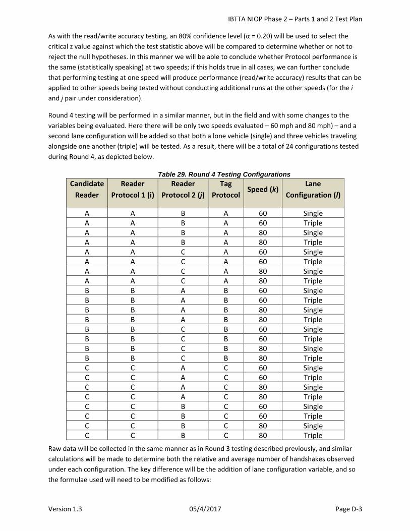
IBTTA NIOP Phase 2 – Parts 1 and 2 Test Plan
Version 1.3 05/4/2017 Page D-3
As with the read/write accuracy testing, an 80% confidence level (α = 0.20) will be used to select the critical z value against which the test statistic above will be compared to determine whether or not to reject the null hypotheses. In this manner we will be able to conclude whether Protocol performance is the same (statistically speaking) at two speeds; if this holds true in all cases, we can further conclude that performing testing at one speed will produce performance (read/write accuracy) results that can be applied to other speeds being tested without conducting additional runs at the other speeds (for the i and j pair under consideration).
Round 4 testing will be performed in a similar manner, but in the field and with some changes to the variables being evaluated. Here there will be only two speeds evaluated – 60 mph and 80 mph) – and a second lane configuration will be added so that both a lone vehicle (single) and three vehicles traveling alongside one another (triple) will be tested. As a result, there will be a total of 24 configurations tested during Round 4, as depicted below.
Table 29. Round 4 Testing Configurations Candidate
Reader Reader
Protocol 1 (i) Reader
Protocol 2 (j) Tag
Protocol Speed (k)
Lane Configuration (l)
A A B A 60 Single A A B A 60 Triple A A B A 80 Single A A B A 80 Triple A A C A 60 Single A A C A 60 Triple A A C A 80 Single A A C A 80 Triple B B A B 60 Single B B A B 60 Triple B B A B 80 Single B B A B 80 Triple B B C B 60 Single B B C B 60 Triple B B C B 80 Single B B C B 80 Triple C C A C 60 Single C C A C 60 Triple C C A C 80 Single C C A C 80 Triple C C B C 60 Single C C B C 60 Triple C C B C 80 Single C C B C 80 Triple
Raw data will be collected in the same manner as in Round 3 testing described previously, and similar calculations will be made to determine both the relative and average number of handshakes observed under each configuration. The key difference will be the addition of lane configuration variable, and so the formulae used will need to be modified as follows:
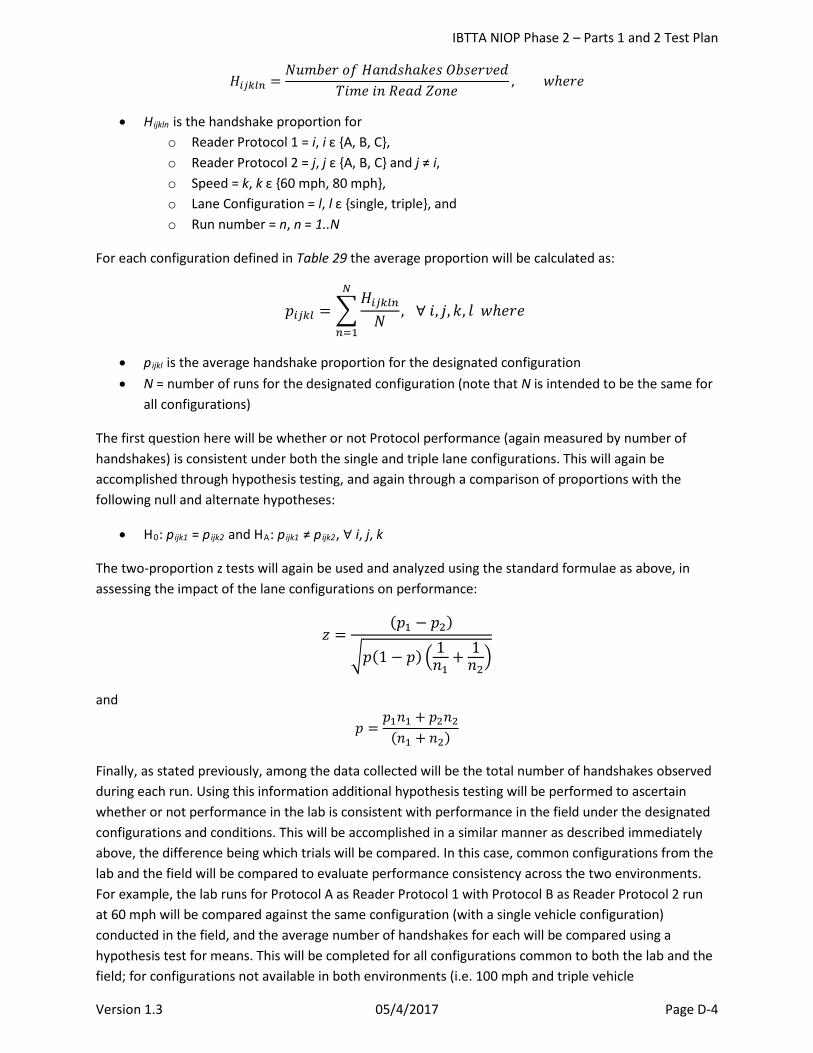
IBTTA NIOP Phase 2 – Parts 1 and 2 Test Plan
Version 1.3 05/4/2017 Page D-4
𝐻𝐻𝑖𝑖𝑖𝑖𝑖𝑖𝑖𝑖𝑖𝑖 =𝑁𝑁𝑁𝑁𝑁𝑁𝑁𝑁𝑁𝑁𝑁𝑁 𝑜𝑜𝑜𝑜 𝐻𝐻𝐻𝐻𝐻𝐻𝐻𝐻𝐻𝐻ℎ𝐻𝐻𝑎𝑎𝑁𝑁𝐻𝐻 𝑂𝑂𝑁𝑁𝐻𝐻𝑁𝑁𝑁𝑁𝑂𝑂𝑁𝑁𝐻𝐻
𝑇𝑇𝑇𝑇𝑁𝑁𝑁𝑁 𝑇𝑇𝐻𝐻 𝑅𝑅𝑁𝑁𝐻𝐻𝐻𝐻 𝑍𝑍𝑜𝑜𝐻𝐻𝑁𝑁, 𝑤𝑤ℎ𝑁𝑁𝑁𝑁𝑁𝑁
• Hijkln is the handshake proportion for o Reader Protocol 1 = i, i ε {A, B, C}, o Reader Protocol 2 = j, j ε {A, B, C} and j ≠ i, o Speed = k, k ε {60 mph, 80 mph}, o Lane Configuration = l, l ε {single, triple}, and o Run number = n, n = 1..N
For each configuration defined in Table 29 the average proportion will be calculated as:
𝑝𝑝𝑖𝑖𝑖𝑖𝑖𝑖𝑖𝑖 = �𝐻𝐻𝑖𝑖𝑖𝑖𝑖𝑖𝑖𝑖𝑖𝑖𝑁𝑁
, ∀ 𝑇𝑇, 𝑗𝑗,𝑎𝑎, 𝑙𝑙 𝑤𝑤ℎ𝑁𝑁𝑁𝑁𝑁𝑁 𝑁𝑁
𝑖𝑖=1
• pijkl is the average handshake proportion for the designated configuration • N = number of runs for the designated configuration (note that N is intended to be the same for
all configurations)
The first question here will be whether or not Protocol performance (again measured by number of handshakes) is consistent under both the single and triple lane configurations. This will again be accomplished through hypothesis testing, and again through a comparison of proportions with the following null and alternate hypotheses:
• H0: pijk1 = pijk2 and HA: pijk1 ≠ pijk2, ∀ i, j, k
The two-proportion z tests will again be used and analyzed using the standard formulae as above, in assessing the impact of the lane configurations on performance:
𝑧𝑧 =(𝑝𝑝1 − 𝑝𝑝2)
�𝑝𝑝(1 − 𝑝𝑝) � 1𝐻𝐻1
+ 1𝐻𝐻2�
and
𝑝𝑝 =𝑝𝑝1𝐻𝐻1 + 𝑝𝑝2𝐻𝐻2
(𝐻𝐻1 + 𝐻𝐻2)
Finally, as stated previously, among the data collected will be the total number of handshakes observed during each run. Using this information additional hypothesis testing will be performed to ascertain whether or not performance in the lab is consistent with performance in the field under the designated configurations and conditions. This will be accomplished in a similar manner as described immediately above, the difference being which trials will be compared. In this case, common configurations from the lab and the field will be compared to evaluate performance consistency across the two environments. For example, the lab runs for Protocol A as Reader Protocol 1 with Protocol B as Reader Protocol 2 run at 60 mph will be compared against the same configuration (with a single vehicle configuration) conducted in the field, and the average number of handshakes for each will be compared using a hypothesis test for means. This will be completed for all configurations common to both the lab and the field; for configurations not available in both environments (i.e. 100 mph and triple vehicle
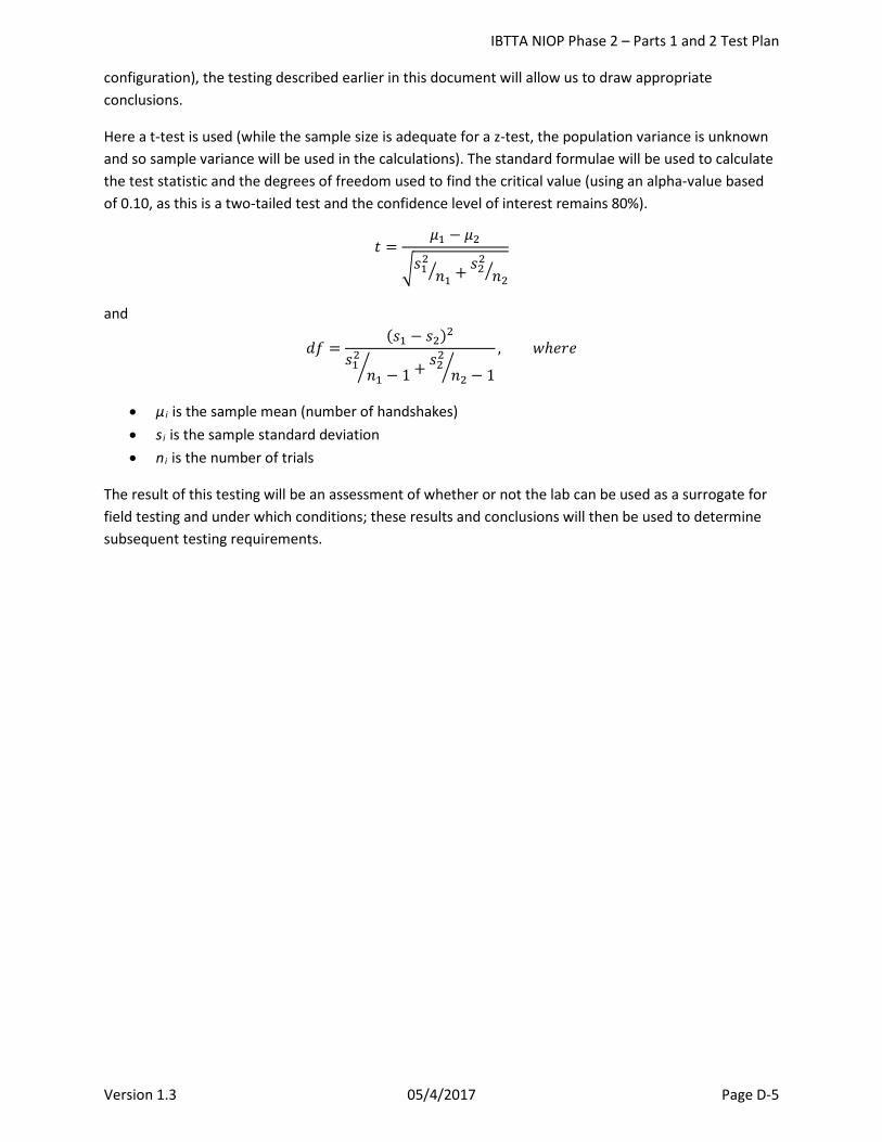
IBTTA NIOP Phase 2 – Parts 1 and 2 Test Plan
Version 1.3 05/4/2017 Page D-5
configuration), the testing described earlier in this document will allow us to draw appropriate conclusions.
Here a t-test is used (while the sample size is adequate for a z-test, the population variance is unknown and so sample variance will be used in the calculations). The standard formulae will be used to calculate the test statistic and the degrees of freedom used to find the critical value (using an alpha-value based of 0.10, as this is a two-tailed test and the confidence level of interest remains 80%).
𝑡𝑡 =𝜇𝜇1 − 𝜇𝜇2
�𝐻𝐻12𝐻𝐻1� + 𝐻𝐻22 𝐻𝐻2�
and
𝐻𝐻𝑜𝑜 =(𝐻𝐻1 − 𝐻𝐻2)2
𝐻𝐻12𝐻𝐻1 − 1� + 𝐻𝐻22
𝐻𝐻2 − 1�, 𝑤𝑤ℎ𝑁𝑁𝑁𝑁𝑁𝑁
• μ i is the sample mean (number of handshakes) • si is the sample standard deviation • ni is the number of trials
The result of this testing will be an assessment of whether or not the lab can be used as a surrogate for field testing and under which conditions; these results and conclusions will then be used to determine subsequent testing requirements.
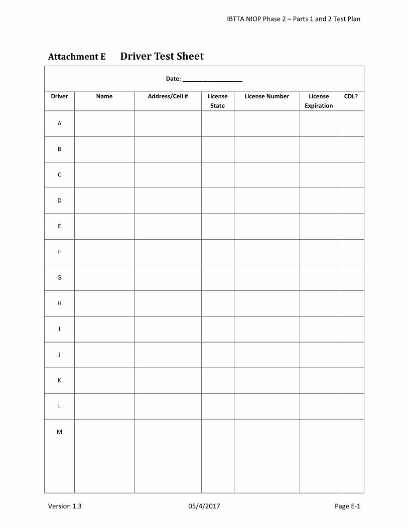
IBTTA NIOP Phase 2 – Parts 1 and 2 Test Plan
Version 1.3 05/4/2017 Page E-1
Attachment E Driver Test Sheet
Date: __________________
Driver Name Address/Cell # License State
License Number License Expiration
CDL?
A
B
C
D
E
F
G
H
I
J
K
L
M

IBTTA NIOP Phase 2 – Parts 1 and 2 Test Plan
Version 1.3 05/4/2017 Page F-1
Attachment F Vehicle Test Sheet
Date: __________________
Vehicle #
Vehicle Type
Make Model Color Plate State
Plate Number Driver
1
2
3
4
5
6
7
8
9
10
11
12
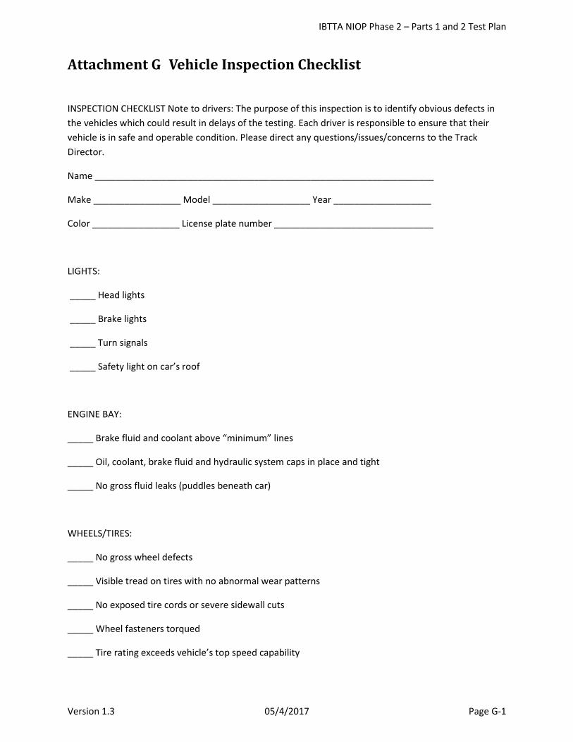
IBTTA NIOP Phase 2 – Parts 1 and 2 Test Plan
Version 1.3 05/4/2017 Page G-1
Attachment G Vehicle Inspection Checklist
INSPECTION CHECKLIST Note to drivers: The purpose of this inspection is to identify obvious defects in the vehicles which could result in delays of the testing. Each driver is responsible to ensure that their vehicle is in safe and operable condition. Please direct any questions/issues/concerns to the Track Director.
Name __________________________________________________________________
Make _________________ Model ___________________ Year ___________________
Color _________________ License plate number _______________________________
LIGHTS:
_____ Head lights
_____ Brake lights
_____ Turn signals
_____ Safety light on car’s roof
ENGINE BAY:
_____ Brake fluid and coolant above “minimum” lines
_____ Oil, coolant, brake fluid and hydraulic system caps in place and tight
_____ No gross fluid leaks (puddles beneath car)
WHEELS/TIRES:
_____ No gross wheel defects
_____ Visible tread on tires with no abnormal wear patterns
_____ No exposed tire cords or severe sidewall cuts
_____ Wheel fasteners torqued
_____ Tire rating exceeds vehicle’s top speed capability
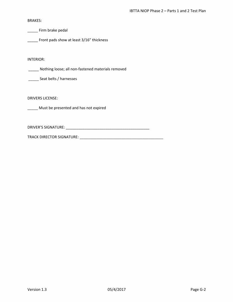
IBTTA NIOP Phase 2 – Parts 1 and 2 Test Plan
Version 1.3 05/4/2017 Page G-2
BRAKES:
_____ Firm brake pedal
_____ Front pads show at least 3/16” thickness
INTERIOR:
_____ Nothing loose; all non-fastened materials removed
_____ Seat belts / harnesses
DRIVERS LICENSE:
_____ Must be presented and has not expired
DRIVER’S SIGNATURE: ________________________________________
TRACK DIRECTOR SIGNATURE: ________________________________________
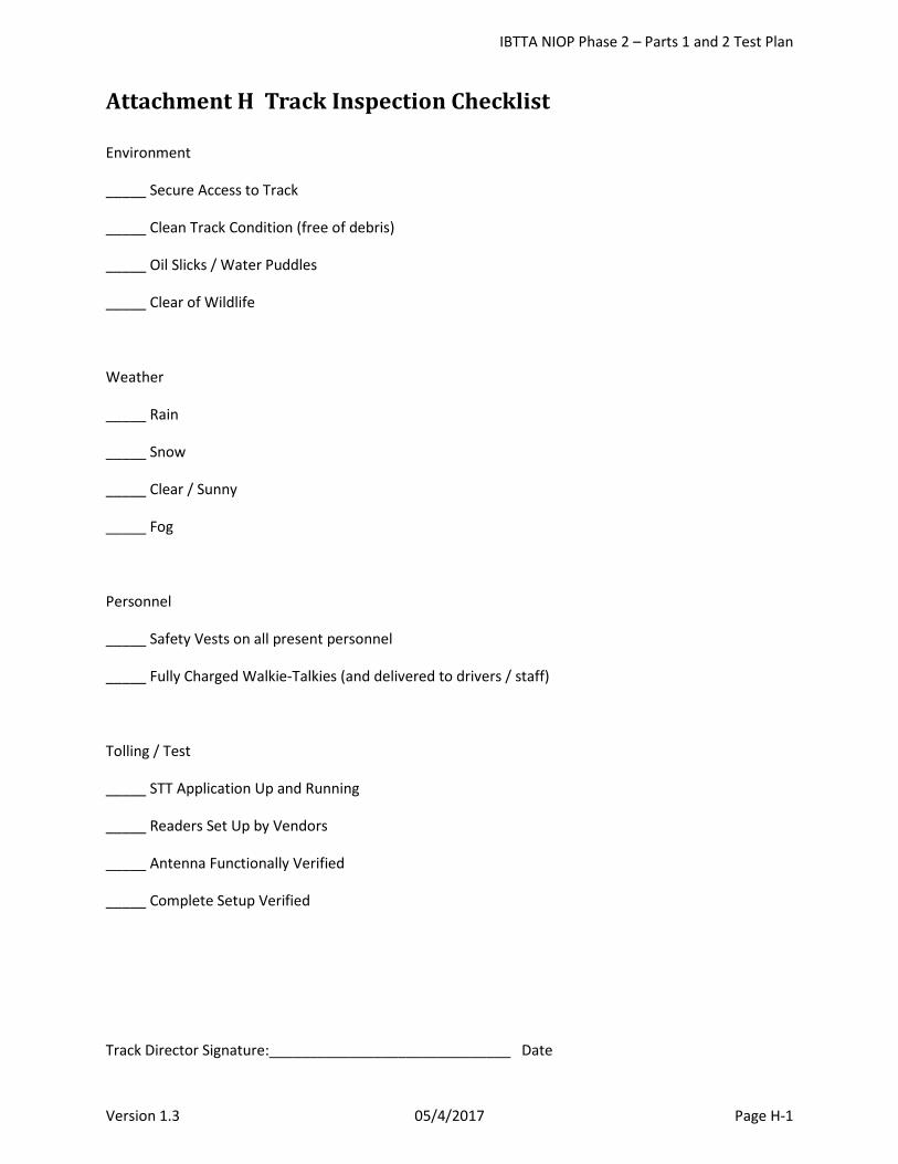
IBTTA NIOP Phase 2 – Parts 1 and 2 Test Plan
Version 1.3 05/4/2017 Page H-1
Attachment H Track Inspection Checklist Environment
_____ Secure Access to Track
_____ Clean Track Condition (free of debris)
_____ Oil Slicks / Water Puddles
_____ Clear of Wildlife
Weather
_____ Rain
_____ Snow
_____ Clear / Sunny
_____ Fog
Personnel
_____ Safety Vests on all present personnel
_____ Fully Charged Walkie-Talkies (and delivered to drivers / staff)
Tolling / Test
_____ STT Application Up and Running
_____ Readers Set Up by Vendors
_____ Antenna Functionally Verified
_____ Complete Setup Verified
Track Director Signature:______________________________ Date


![0!123 - zgrkkx.com · *+,-./0123456789:;?@ABCDEFGHIJKLMN O1PQR/STUVW6XYZ[\]J^_‘Pa.bcdefgPhijkElUhm nIop]6qQ!" rTsQ #" rT[tPuvwxy/z{|1}~ •†‡…6VJK— –Pƒ](https://img.pdfslide.net/doc/110x75/5cdfed8188c993f4758cf7c0/0123-0123456789abcdefghijklmn-o1pqrstuvw6xyzjpabcdefgphijkeluhm.jpg)