Embed Size (px)
Citation preview
ICS(P)A Cartesian Robot Assembly Procedures Fifth Edition
Thank you for purchasing an IAI product. Assemble your product correctly by referring to this Assembly Procedures. Be sure to read the operation manual (CD/DVD) supplied separately for each actuator and handle the actuator correctly
Wiring method/type No. Number of
configured axes Mounting method Between X-axis and Y-axis Between Y-axis and Z-axis Between X-axis and Z-axis Between Y-axis and ZR-axis
Model Drawing No. Completed Drawing List
Drawing No. Assembly Procedures
1 2 axes Y-axis base Self-supporting cable - - - ICS(P)A2-B -SC GMM09-001(1/2) GMM08-003
2 2 axes Y-axis base Cable track - - - ICS(P)A2-B -CT GMM09-001(1/2) GMM08-004
3 2 axes Gantry Cable track - - - ICS(P)A2-G -CT GMM09-001(1/2) GMM08-005
4 2 axes Y-axis slider Self-supporting cable - - - ICS(P)A2-S -SC GMM09-001(1/2) GMM08-006
5 2 axes Y-axis slider - Self-supporting cable - - ICS(P)A2-Y -SC GMM09-001(1/2) GMM08-007
6 2 axes Z-axis base - - Cable track - ICS(P)A2-Z -CT GMM09-001(1/2) GMM08-008
7 3 axes X-Y base, Z-axis base Cable track Cable track - - ICS(P)A3-B B -CT-CT GMM09-001(2/2) GMM08-009
8 3 axes X-Y base, Z-axis base Cable track Self-supporting cable - - ICS(P)A3-B B -CT-SC GMM09-001(2/2) GMM08-010
9 3 axes X-Y base, Z-axis base Self-supporting cable Self-supporting cable - - ICS(P)A3-B B -SC-SC GMM09-001(2/2) GMM08-011
10 3 axes X-Y base, Z-axis slider Self-supporting cable Self-supporting cable - - ICS(P)A3-B S -SC-SC GMM09-001(2/2) GMM08-012
11 3 axes X-Y gantry, Z-axis base Cable track Cable track - - ICS(P)A3-G B -CT-CT GMM09-001(2/2) GMM08-013
12 3 axes X-Y gantry, Z-axis slider Cable track Cable track Self-supporting cable - ICS(P)A3-G S -CT-SC GMM09-001(2/2) GMM08-014
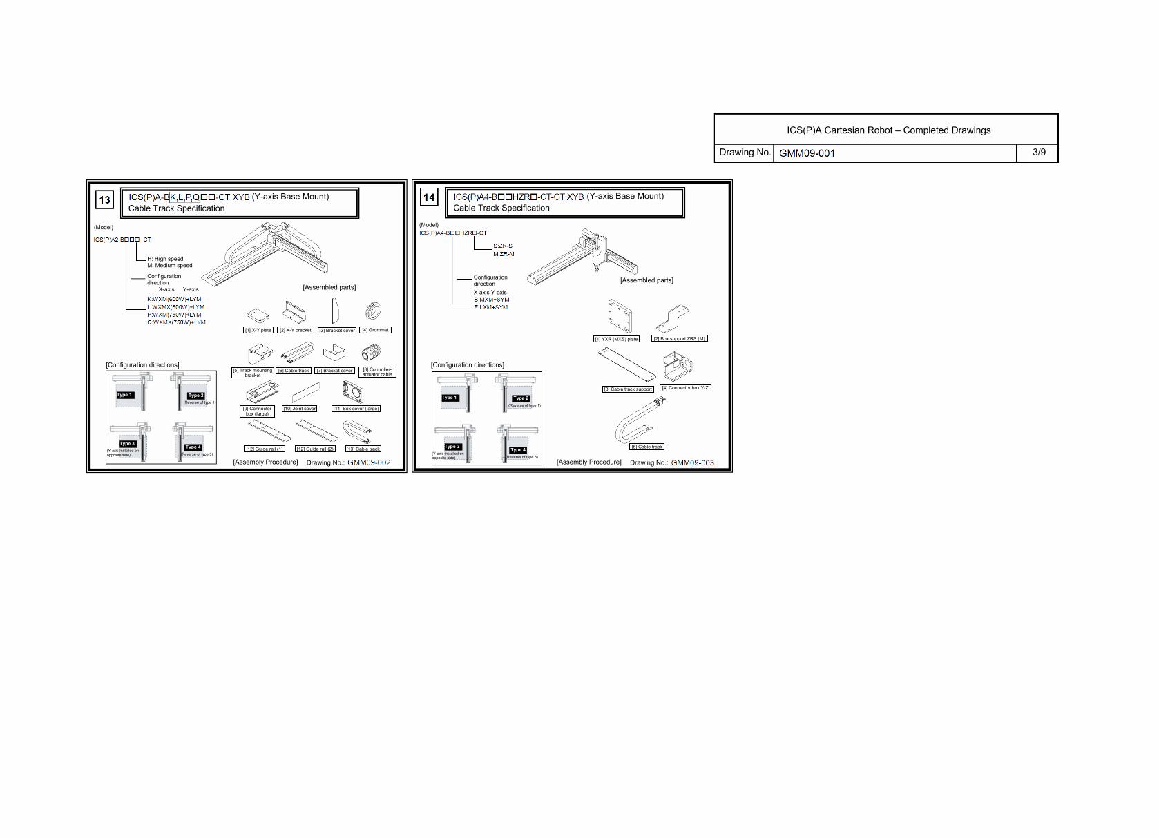
13 2 axes Y-axis base Cable track - ICS(P)A2-BK,L,P,Q -CT GMM09-001(3/3) GMM09-002
14 4 axes Y-axis mount Cable track Cable track ICS(P)A4-B HZR -CT-CT GMM09-001(3/3) GMM09-003
15 Instruction for Cable Track Type Wiring GMM12-001Catalog No.: ME0215-5A
Drawing No.
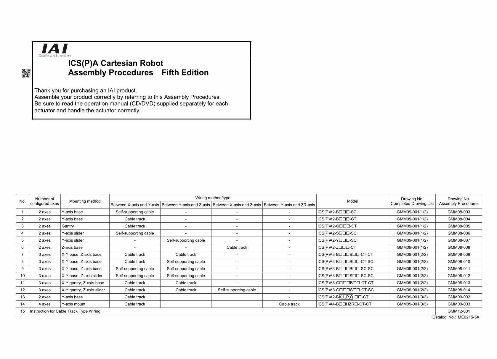
ICS(P)A Cartesian Robot – Completed Drawings
(X-axis Base Mount) Self-supporting Cable Specification
(Model) (Model)
(Model)
(Model) (Model)
(Model)
H: High speed M: Medium speed
Configuration direction
X-axis Y-axis
H: High speed M: Medium speed
Configuration direction
X-axis Y-axis
[Configuration directions]
[Assembled parts]
[Configuration directions]
[Assembled parts]
[Configuration directions]
[Assembled parts]
[Configuration directions]
[Assembled parts]
[Configuration directions]
[Assembled parts]
[Configuration directions]
[Assembled parts]
Type 1 Type 2 (Reverse of type 1)
Type 3 (Y-axis installed on opposite side)
Type 4 (Reverse of type )
[1] X-Y bracket [2] Box cover [3] Connector box (small)
[4] Connector box (large) [5] Bracket cover [6] Grommet with film
[7] Cable fix cap [8] Joint cover
[9] Self-supporting cable assembly
[Assembly Procedure] Drawing No.:
Type 1 Type 2(Reverse of type 1)
Type 3 (Y-axis installed on opposite side)
Type 4(Reverse of type 3)
[1] X-Y bracket [2] Box cover [3] Connector box
[4] Box spacer, BA type only
[5] Joint cover [6] Bracket cover
[7] Grommet with film ( 30, 34)
[8] Cable fix cap [9] Guide rail
[10] Cable track[2], [3], [5] and [9] are assembled before the shipment.
[Assembly Procedure] Drawing No.: [Assembly Procedure] Drawing No.:
[Assembly Procedure] Drawing No.: [Assembly Procedure] Drawing No.: [Assembly Procedure] Drawing No.:
(Y-axis Base Mount) Cable Track Specification
(Gantry) TypeCable Track Specification
(Y-axis Slider Mount) Self-supporting Cable Specification
(Y-axis Slider Mount) (Z-axis Base Mount)
H: High speed
X-axis Y-axis
[1] X-Y bracket (1) [2] X-Y bracket [3] Pin bracket
[4] Spacer [5] Mounting bracket [6] Guide rail
[7] Connector box (small) [8] Box cover [9] Joint cover
[10] Connector box (large) [11] Cable track [12] Grommet with film
[13] Cable fix cap [14] Packing frame
Cable track assembly
[5], [6] and [11] are assembled before the shipment.
H: High speed M: Medium speed
Configuration direction
X-axis Y-axis [1] X-Y bracket [2] Box cover [3] Connector box (small)
[4] Connector box (large) [5] Bracket cover [6] Grommet with film
[7] Cable fix cap [8] Joint cover
[10] Self-supporting cable assembly
[8] Mounting bracket Combination direction: 1
(Operation range)
Combination direction: 2
(Reverse of 1) (Operation range)
Combination direction: 3
(Y-axis installed on opposite side)
(Operation range)
Combination direction: 4
(Reverse of 1) (Operation range)
H: High speed M: Medium speed
Y-axis Z-axis
[1] X-Y bracket [2] Box cover [3] Connector box (small)
[4] Connector box (large) [5] Grommet with film [6] Cable fix cap
[7] Joint cover [8] Box spacer
[9] Self-supporting cable assembly
H: High speed M: Medium speed
X-axis Y-axis
[1] X-Y bracket [2] Box cover [3] Connector box (small)
[3] Connector box (large)
[4] Joint cover [5] Mounting bracket[6] Grommet with film
( 30, 34)
[7] Cable fix cap [8] Guide rail [9] Cable track
[6], [9] and [10] are assembled before the shipment.
1/9
Drawing No.
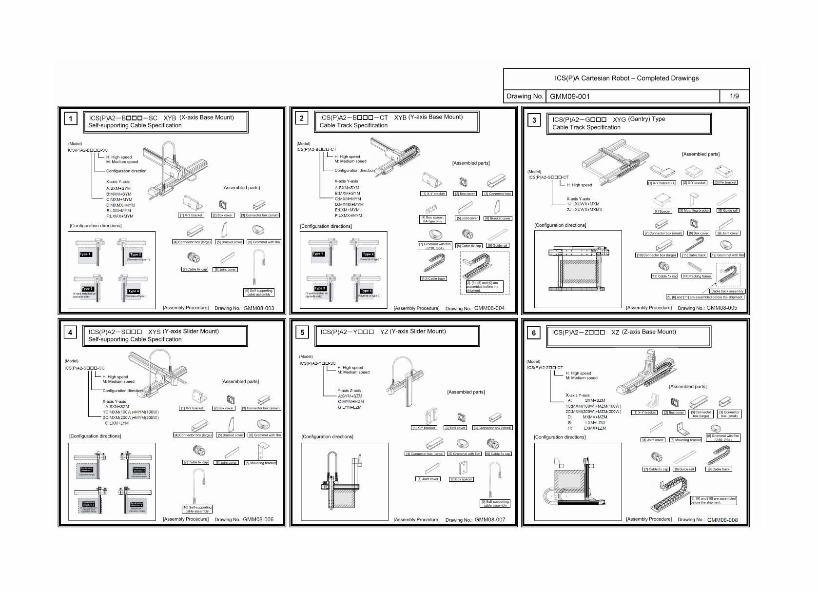
ICS(P)A Cartesian Robot – Completed Drawings
X-Y Base Mount (XYB) + Z-axis, Z-axis Slider Mount X-Y Gantry Configuration (XYG) + Z-axis, Z-axis Base Mount
X-Y Base Mount (XYB) + Z-axis, Z-axis Base Mount X-Y Base Mount (XYB) + Z-axis, Z-axis Base Mount
X-Y Gantry Configuration (XYG) + Z-axis Slider Mount
X-Y Base Mount (XYB) + Z-axis, Z-axis Base Mount
H: High speed M: Medium speed
Z-axis
[Configuration directions]
[Assembled parts]
[Assembly Procedure] Drawing No.:
[Configuration directions]
[Assembled parts]
[Assembly Procedure] Drawing No.:
[Configuration directions]
[Assembled parts]
[Assembly Procedure] Drawing No.:
[Configuration directions]
[Assembled parts]
[Assembly Procedure] Drawing No.:
[Configuration directions]
[Assembled parts]
[Assembly Procedure] Drawing No.:
[Configuration directions]
[Assembled parts]
[Assembly Procedure] Drawing No.:
Configuration direction
X-axis Y-axis
Type 1 Type 2 (Reverse of type 1)
Type 3 (Y-axis installed on opposite side)
Type 4 (Reverse of type 3)
[1] X-Y bracket [4] Connector box (medium)
[3] Connector box (large)
[2] Y-Z bracket
[5] Connector box (small)
[6] Joint cover (large)
[7] Joint cover (medium)
[8] Joint cover (small)
[9] Box cover [10] Bracket cover [11] Grommet with film
[12] Cable fix cap
[13] Box support
[14] Cable track assembly
[14] Cable track assembly Guide rail Cable track mounting bracket Connector box Box cover Cable track The above parts are supplied as a set.
H: High speed M: Medium speed
Z-axis
Configuration direction
X-axis Y-axis
H: High speedM: Medium speed
Type 1 Type 2(Reverse of type 1)
Type 3 Type 3
[1] X-Y bracket [4] Connector box (medium)
[3] Connector box (large)
[2] Y-Z bracket
[5] Connector box (small)
[6] Joint cover (large)
[7] Joint cover(medium)
[8] Joint cover(small)
[9] Box cover [10] Bracket cover [11] Grommetwith film
[12] Cable fix cap
[13] Box support
[14] Cable track assembly
(Y-axis installed on opposite side) (Reverse of type 3)
[15] Self-supporting cable assembly (2)
H: High speed M: Medium speed
Z-axis
Configuration direction
X-axis Y-axis
H: High speed M: Medium speed
[1] X-Y bracket [4] Connector box (medium)
[3] Connector box (large)
[2] Y-Z bracket
[5] Connector box (small)
[6] Box cover [7] Joint cover (large)
[8] Joint cover(medium)
[9] Joint cover(small)
[10] Bracket cover [11] Grommetwith film
[12] Cable fix cap
[13] Box support
[14] Self-supporting cable assembly (1)
[15] Self-supporting cable assembly (2)
Type 1 Type 2 (Reverse of type 1)
Type 3(Y-axis installed on opposite side)
Type 4 (Reverse of type 3)
H: High speed M: Medium speed
Z-axis
X-axis Y-axis
Type 1 Type 2 (Reverse of type 1)
Type 3 (Y-axis installed on opposite side)
Type 4 (Reverse of type 3)
Configuration direction
H: High speed M: Medium speed
[1] X-Y bracket [4] Connector box (medium)
[3] Connector box (large)
[2] Y-Z bracket
[5] Connector box (small)
[6] Box cover [7] Joint cover (large)
[8] Joint cover (medium)
[9] Joint cover (small)
[10] Bracket cover [11] Grommet with film
[12] Cable fix cap
[13] Box support
[14] Self-supporting cable assembly (1)
[15] Self-supporting cable assembly (2)
Z-axisH: High speed
M: Medium speedL: Low speed
Z-axis
X-axis Y-axis
H: High speed
[1] X-Y bracket (1) [2] X-Y bracket (2) [3] Pin bracket [4] Spacer
[5] Y-Z bracket [6] Y-Z plate [7] Mounting bracket (1)
[8] Mounting bracket (2)
[9] Guide rail (1) [10] Guide rail (2) [12] Connector box (medium)
[11] Connector box (large)
[13] Connector box (small)
[14] Box cover[15] Joint
cover (large)[16] Joint cover
(medium)
[17] Joint cover (small)
[18] Cable track [19] Grommet with film
[20] Packing frame
* Cable track assemblyThe cable track assembly is configured with the mounting bracket and guide rail.
Z-axisH: High speed
M: Medium speedL: Low speed
Z-axis
X-axis Y-axis
H: High speed
[1] X-Y bracket (1) [2] X-Y bracket (2) [3] Pin bracket [4] Spacer
[5] Y-Z bracket [6] Mounting bracket (1)
[7] Mounting bracket (2)
[8] Guide rail (1) [9] Guide rail (2) [10] Connector box (large)
[11] Joint cover
[12] Box cover [13] Cable track
[14] Packing frame[15] Self-supporting cable assembly
* Cable track assembly The cable track assembly is configured with the mounting bracket and guide rail.
(Model)(Model)
(Model)(Model)
2/9
(Model)
(Model)
Drawing No.
ICS(P)A Cartesian Robot – Completed Drawings
Cable Track Specification
[Configuration directions]
[Assembled parts]
[Assembly Procedure] Drawing No.:
H: High speed M: Medium speed
Configuration direction
X-axis Y-axis
[Configuration directions]
[Assembled parts]
[Assembly Procedure] Drawing No.:
Configuration direction X-axis Y-axis
Type 1 Type 2 (Reverse of type 1)
Type 3 (Y-axis installed on opposite side)
Type 4 (Reverse of type 3)
Type 1 Type 2(Reverse of type 1)
Type 3 (Y-axis installed on opposite side)
Type 4(Reverse of type 3)
[1] X-Y plate [3] Bracket cover [2] X-Y bracket [4] Grommet
[5] Track mounting bracket
[6] Cable track [7] Bracket cover [8] Controller-actuator cable
[9] Connector box (large)
[10] Joint cover [11] Box cover (large)
[13] Cable track [12] Guide rail (1) [12] Guide rail (2)
(Y-axis Base Mount)Cable Track Specification
(Y-axis Base Mount)
[1] YXR (MXS) plate [2] Box support ZRS (M)
[3] Cable track support [4] Connector box Y-Z
[5] Cable track
(Model) (Model)
3/9
ICS(P)A Cartesian Robot – Completed Drawings
Drawing No. GMM09-001 4/9
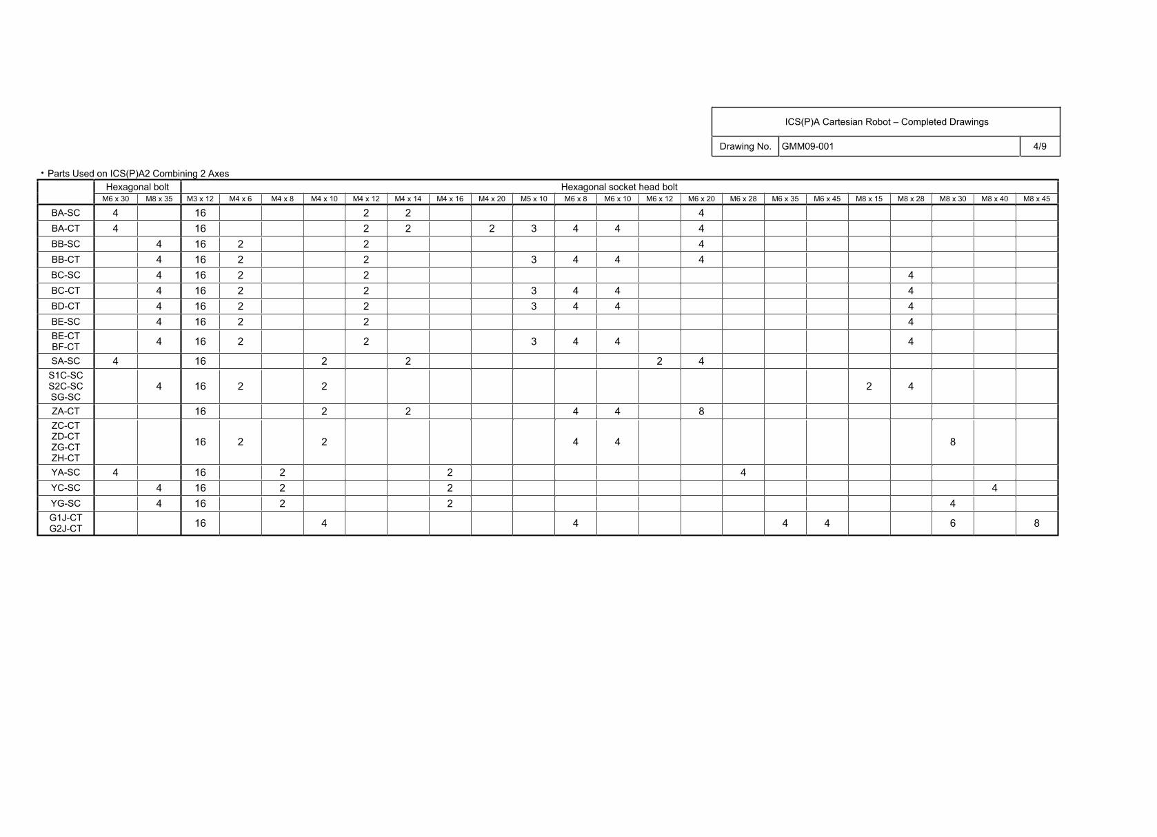
Parts Used on ICS(P)A2 Combining 2 AxesHexagonal bolt Hexagonal socket head bolt
M6 x 30 M8 x 35 M3 x 12 M4 x 6 M4 x 8 M4 x 10 M4 x 12 M4 x 14 M4 x 16 M4 x 20 M5 x 10 M6 x 8 M6 x 10 M6 x 12 M6 x 20 M6 x 28 M6 x 35 M6 x 45 M8 x 15 M8 x 28 M8 x 30 M8 x 40 M8 x 45
BA-SC 4 16 2 2 4BA-CT 4 16 2 2 2 3 4 4 4BB-SC 4 16 2 2 4BB-CT 4 16 2 2 3 4 4 4BC-SC 4 16 2 2 4BC-CT 4 16 2 2 3 4 4 4BD-CT 4 16 2 2 3 4 4 4BE-SC 4 16 2 2 4BE-CTBF-CT 4 16 2 2 3 4 4 4
SA-SC 4 16 2 2 2 4S1C-SC S2C-SC SG-SC
4 16 2 2 2 4
ZA-CT 16 2 2 4 4 8ZC-CTZD-CTZG-CTZH-CT
16 2 2 4 4 8
YA-SC 4 16 2 2 4YC-SC 4 16 2 2 4YG-SC 4 16 2 2 4G1J-CTG2J-CT 16 4 4 4 4 6 8
ICS(P)A Cartesian Robot – Completed Drawings
Drawing No. GMM09-001 5/9
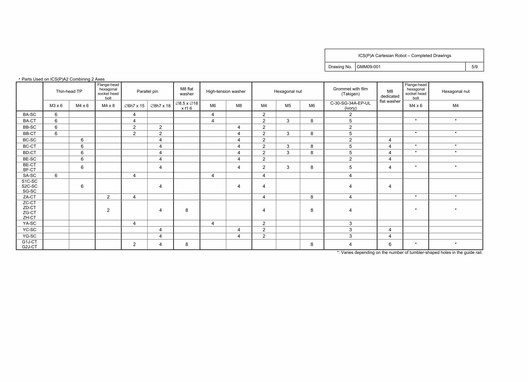
Parts Used on ICS(P)A2 Combining 2 Axes
Thin-head TPFlange-head hexagonal
socket head bolt
Parallel pin M8 flat washer High-tension washer Hexagonal nut Grommet with film
(Takigen)
Flange-head hexagonal
socket head bolt
Hexagonal nut
M3 x 6 M4 x 6 M4 x 8 6h7 x 15 8h7 x 18 8.5 x 18x t1.6 M6 M8 M4 M5 M6 C-30-SG-34A-EP-UL
(ivory)
M8dedicated flat washer
M4 x 6 M4
BA-SC 6 4 4 2 2BA-CT 6 4 4 2 3 8 5 * *BB-SC 6 2 2 4 2 2BB-CT 6 2 2 4 2 3 8 5 * *BC-SC 6 4 4 2 2 4BC-CT 6 4 4 2 3 8 5 4 * *BD-CT 6 4 4 2 3 8 5 4 * *BE-SC 6 4 4 2 2 4BE-CTBF-CT 6 4 4 2 3 8 5 4 * *
SA-SC 6 4 4 4 4S1C-SC S2C-SC SG-SC
6 4 4 4 4 4
ZA-CT 2 4 4 8 4 * *ZC-CTZD-CTZG-CTZH-CT
2 4 8 4 8 4 * *
YA-SC 4 4 2 3YC-SC 4 4 2 3 4YG-SC 4 4 2 3 4G1J-CTG2J-CT 2 4 8 8 4 6 * *
*: Varies depending on the number of tumbler-shaped holes in the guide rail.
ICS(P)A Cartesian Robot – Completed Drawings
Drawing No. GMM09-001 6/9
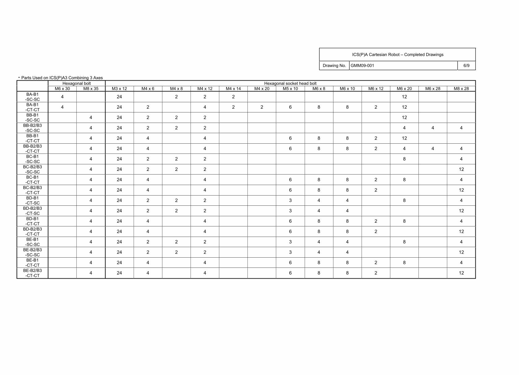
Parts Used on ICS(P)A3 Combining 3 AxesHexagonal bolt Hexagonal socket head bolt
M6 x 30 M8 x 35 M3 x 12 M4 x 6 M4 x 8 M4 x 12 M4 x 14 M4 x 20 M5 x 10 M6 x 8 M6 x 10 M6 x 12 M6 x 20 M6 x 28 M8 x 28BA-B1
-SC-SC 4 24 2 2 2 12
BA-B1-CT-CT 4 24 2 4 2 2 6 8 8 2 12
BB-B1-SC-SC 4 24 2 2 2 12
BB-B2/B3-SC-SC 4 24 2 2 2 4 4 4
BB-B1-CT-CT 4 24 4 4 6 8 8 2 12
BB-B2/B3-CT-CT 4 24 4 4 6 8 8 2 4 4 4
BC-B1-SC-SC 4 24 2 2 2 8 4
BC-B2/B3-SC-SC 4 24 2 2 2 12
BC-B1-CT-CT 4 24 4 4 6 8 8 2 8 4
BC-B2/B3-CT-CT 4 24 4 4 6 8 8 2 12
BD-B1-CT-SC 4 24 2 2 2 3 4 4 8 4
BD-B2/B3-CT-SC 4 24 2 2 2 3 4 4 12
BD-B1-CT-CT 4 24 4 4 6 8 8 2 8 4
BD-B2/B3-CT-CT 4 24 4 4 6 8 8 2 12
BE-B1-SC-SC 4 24 2 2 2 3 4 4 8 4
BE-B2/B3-SC-SC 4 24 2 2 2 3 4 4 12
BE-B1-CT-CT 4 24 4 4 6 8 8 2 8 4
BE-B2/B3-CT-CT 4 24 4 4 6 8 8 2 12
ICS(P)A Cartesian Robot – Completed Drawings
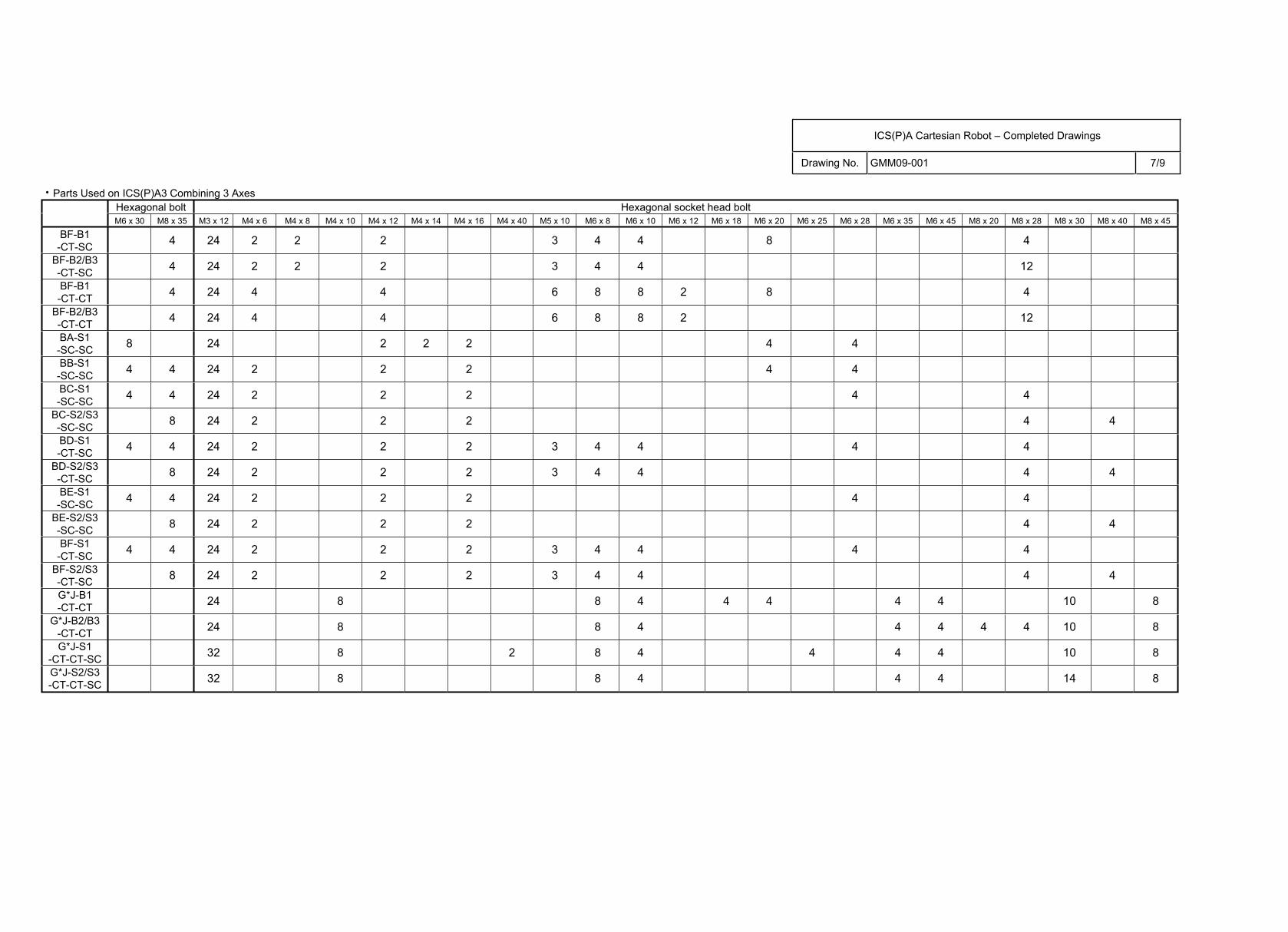
Drawing No. GMM09-001 7/9
Parts Used on ICS(P)A3 Combining 3 AxesHexagonal bolt Hexagonal socket head bolt M6 x 30 M8 x 35 M3 x 12 M4 x 6 M4 x 8 M4 x 10 M4 x 12 M4 x 14 M4 x 16 M4 x 40 M5 x 10 M6 x 8 M6 x 10 M6 x 12 M6 x 18 M6 x 20 M6 x 25 M6 x 28 M6 x 35 M6 x 45 M8 x 20 M8 x 28 M8 x 30 M8 x 40 M8 x 45
BF-B1-CT-SC 4 24 2 2 2 3 4 4 8 4
BF-B2/B3-CT-SC 4 24 2 2 2 3 4 4 12
BF-B1-CT-CT 4 24 4 4 6 8 8 2 8 4
BF-B2/B3-CT-CT 4 24 4 4 6 8 8 2 12
BA-S1-SC-SC 8 24 2 2 2 4 4
BB-S1-SC-SC 4 4 24 2 2 2 4 4
BC-S1-SC-SC 4 4 24 2 2 2 4 4
BC-S2/S3-SC-SC 8 24 2 2 2 4 4
BD-S1-CT-SC 4 4 24 2 2 2 3 4 4 4 4
BD-S2/S3-CT-SC 8 24 2 2 2 3 4 4 4 4
BE-S1-SC-SC 4 4 24 2 2 2 4 4
BE-S2/S3-SC-SC 8 24 2 2 2 4 4
BF-S1-CT-SC 4 4 24 2 2 2 3 4 4 4 4
BF-S2/S3-CT-SC 8 24 2 2 2 3 4 4 4 4
G*J-B1-CT-CT 24 8 8 4 4 4 4 4 10 8
G*J-B2/B3-CT-CT 24 8 8 4 4 4 4 4 10 8
G*J-S1-CT-CT-SC 32 8 2 8 4 4 4 4 10 8
G*J-S2/S3-CT-CT-SC 32 8 8 4 4 4 14 8
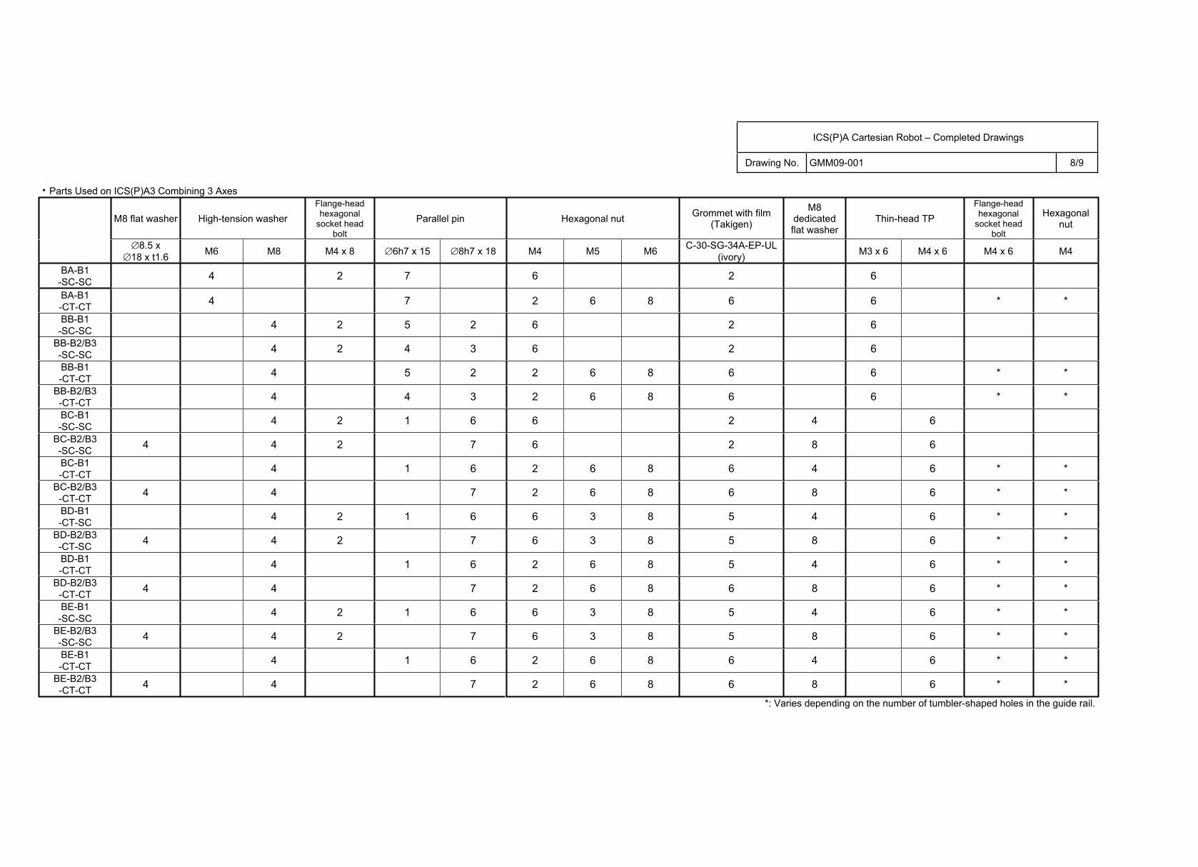
ICS(P)A Cartesian Robot – Completed Drawings
Drawing No. GMM09-001 8/9
Parts Used on ICS(P)A3 Combining 3 Axes
M8 flat washer High-tension washer Flange-head hexagonal
socket head bolt
Parallel pin Hexagonal nut Grommet with film (Takigen)
M8dedicated flat washer
Thin-head TP Flange-head hexagonal
socket head bolt
Hexagonal nut
8.5 x 18 x t1.6 M6 M8 M4 x 8 6h7 x 15 8h7 x 18 M4 M5 M6 C-30-SG-34A-EP-UL
(ivory) M3 x 6 M4 x 6 M4 x 6 M4
BA-B1-SC-SC 4 2 7 6 2 6
BA-B1-CT-CT 4 7 2 6 8 6 6 * *
BB-B1-SC-SC 4 2 5 2 6 2 6
BB-B2/B3-SC-SC 4 2 4 3 6 2 6
BB-B1-CT-CT 4 5 2 2 6 8 6 6 * *
BB-B2/B3-CT-CT 4 4 3 2 6 8 6 6 * *
BC-B1-SC-SC 4 2 1 6 6 2 4 6
BC-B2/B3-SC-SC 4 4 2 7 6 2 8 6
BC-B1-CT-CT 4 1 6 2 6 8 6 4 6 * *
BC-B2/B3-CT-CT 4 4 7 2 6 8 6 8 6 * *
BD-B1-CT-SC 4 2 1 6 6 3 8 5 4 6 * *
BD-B2/B3-CT-SC 4 4 2 7 6 3 8 5 8 6 * *
BD-B1-CT-CT 4 1 6 2 6 8 5 4 6 * *
BD-B2/B3-CT-CT 4 4 7 2 6 8 6 8 6 * *
BE-B1-SC-SC 4 2 1 6 6 3 8 5 4 6 * *
BE-B2/B3-SC-SC 4 4 2 7 6 3 8 5 8 6 * *
BE-B1-CT-CT 4 1 6 2 6 8 6 4 6 * *
BE-B2/B3-CT-CT 4 4 7 2 6 8 6 8 6 * *
*: Varies depending on the number of tumbler-shaped holes in the guide rail.
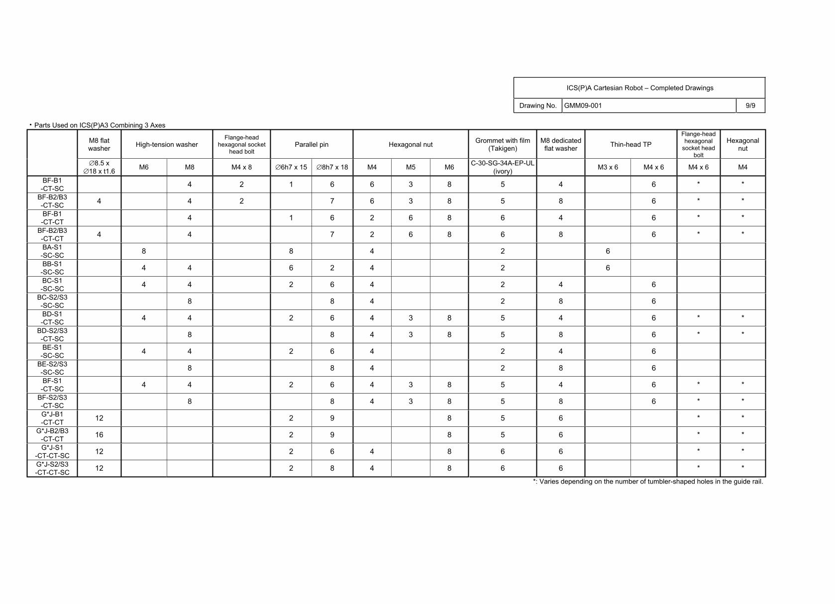
ICS(P)A Cartesian Robot – Completed Drawings
Drawing No. GMM09-001 9/9
Parts Used on ICS(P)A3 Combining 3 Axes
M8 flat washer High-tension washer
Flange-head hexagonal socket
head boltParallel pin Hexagonal nut Grommet with film
(Takigen)M8 dedicated
flat washer Thin-head TP Flange-head hexagonal
socket head bolt
Hexagonal nut
8.5 x 18 x t1.6 M6 M8 M4 x 8 6h7 x 15 8h7 x 18 M4 M5 M6 C-30-SG-34A-EP-UL
(ivory) M3 x 6 M4 x 6 M4 x 6 M4
BF-B1-CT-SC 4 2 1 6 6 3 8 5 4 6 * *
BF-B2/B3-CT-SC 4 4 2 7 6 3 8 5 8 6 * *
BF-B1-CT-CT 4 1 6 2 6 8 6 4 6 * *
BF-B2/B3-CT-CT 4 4 7 2 6 8 6 8 6 * *
BA-S1-SC-SC 8 8 4 2 6
BB-S1-SC-SC 4 4 6 2 4 2 6
BC-S1-SC-SC 4 4 2 6 4 2 4 6
BC-S2/S3-SC-SC 8 8 4 2 8 6
BD-S1-CT-SC 4 4 2 6 4 3 8 5 4 6 * *
BD-S2/S3-CT-SC 8 8 4 3 8 5 8 6 * *
BE-S1-SC-SC 4 4 2 6 4 2 4 6
BE-S2/S3-SC-SC 8 8 4 2 8 6
BF-S1-CT-SC 4 4 2 6 4 3 8 5 4 6 * *
BF-S2/S3-CT-SC 8 8 4 3 8 5 8 6 * *
G*J-B1-CT-CT 12 2 9 8 5 6 * *
G*J-B2/B3-CT-CT 16 2 9 8 5 6 * *
G*J-S1-CT-CT-SC 12 2 6 4 8 6 6 * *
G*J-S2/S3-CT-CT-SC 12 2 8 4 8 6 6 * *
*: Varies depending on the number of tumbler-shaped holes in the guide rail.
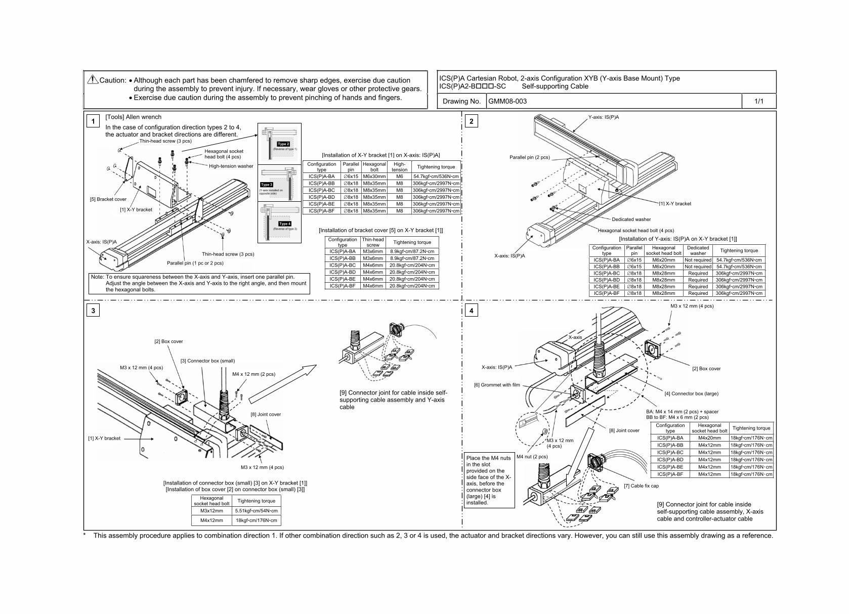
ICS(P)A Cartesian Robot, 2-axis Configuration XYB (Y-axis Base Mount) Type ICS(P)A2-B -SC Self-supporting Cable
Caution: Although each part has been chamfered to remove sharp edges, exercise due caution during the assembly to prevent injury. If necessary, wear gloves or other protective gears. Exercise due caution during the assembly to prevent pinching of hands and fingers. Drawing No. GMM08-003 1/1
* This assembly procedure applies to combination direction 1. If other combination direction such as 2, 3 or 4 is used, the actuator and bracket directions vary. However, you can still use this assembly drawing as a reference.
1 2
3 4
Configuration type
Parallel pin
Hexagonal bolt
High-tension Tightening torque
ICS(P)A-BA 6x15 M6x30mm M6 54.7kgf cm/536N cmICS(P)A-BB 8x18 M8x35mm M8 306kgf cm/2997N cmICS(P)A-BC 8x18 M8x35mm M8 306kgf cm/2997N cmICS(P)A-BD 8x18 M8x35mm M8 306kgf cm/2997N cmICS(P)A-BE 8x18 M8x35mm M8 306kgf cm/2997N cmICS(P)A-BF 8x18 M8x35mm M8 306kgf cm/2997N cm
Configuration type
Thin-headscrew Tightening torque
ICS(P)A-BA M3x6mm 8.9kgf cm/87.2N cmICS(P)A-BB M3x6mm 8.9kgf cm/87.2N cmICS(P)A-BC M4x6mm 20.8kgf cm/204N cmICS(P)A-BD M4x6mm 20.8kgf cm/204N cmICS(P)A-BE M4x6mm 20.8kgf cm/204N cmICS(P)A-BF M4x6mm 20.8kgf cm/204N cm
Configuration type
Parallel pin
Hexagonal socket head bolt
Dedicatedwasher Tightening torque
ICS(P)A-BA 6x15 M6x20mm Not required 54.7kgf cm/536N cmICS(P)A-BB 6x15 M6x20mm Not required 54.7kgf cm/536N cmICS(P)A-BC 8x18 M8x28mm Required 306kgf cm/2997N cmICS(P)A-BD 8x18 M8x28mm Required 306kgf cm/2997N cmICS(P)A-BE 8x18 M8x28mm Required 306kgf cm/2997N cmICS(P)A-BF 8x18 M8x28mm Required 306kgf cm/2997N cm
Hexagonal socket head bolt Tightening torque
M3x12mm 5.51kgf cm/54N cm
M4x12mm 18kgf cm/176N cm
Configuration type
Hexagonal socket head bolt Tightening torque
ICS(P)A-BA M4x20mm 18kgf cm/176N cmICS(P)A-BB M4x12mm 18kgf cm/176N cmICS(P)A-BC M4x12mm 18kgf cm/176N cmICS(P)A-BD M4x12mm 18kgf cm/176N cmICS(P)A-BE M4x12mm 18kgf cm/176N cmICS(P)A-BF M4x12mm 18kgf cm/176N cm
[Tools] Allen wrench In the case of configuration direction types 2 to 4, the actuator and bracket directions are different.
Thin-head screw (3 pcs)
[5] Bracket cover
[1] X-Y bracket
Thin-head screw (3 pcs)
Parallel pin (1 pc or 2 pcs)
Hexagonal socket head bolt (4 pcs)
High-tension washer
Type 2 (Reverse of type 1)
Type 3 (Y-axis installed on opposite side)
Type 4 (Reverse of type 3)
X-axis: IS(P)A
Note: To ensure squareness between the X-axis and Y-axis, insert one parallel pin. Adjust the angle between the X-axis and Y-axis to the right angle, and then mount the hexagonal bolts.
Y-axis: IS(P)A
[1] X-Y bracket
Parallel pin (2 pcs)
Dedicated washer
Hexagonal socket head bolt (4 pcs)
X-axis: IS(P)A
[Installation of Y-axis: IS(P)A on X-Y bracket [1]]
[2] Box cover
[3] Connector box (small)
M4 x 12 mm (2 pcs)
[8] Joint cover
[1] X-Y bracket
[Installation of connector box (small) [3] on X-Y bracket [1]] [Installation of box cover [2] on connector box (small) [3]]
[9] Connector joint for cable inside self-supporting cable assembly and Y-axis cable
M3 x 12 mm (4 pcs)
M3 x 12 mm (4 pcs)
M3 x 12 mm (4 pcs)
[2] Box cover
[4] Connector box (large)
BA: M4 x 14 mm (2 pcs) + spacer BB to BF: M4 x 6 mm (2 pcs)
M3 x 12 mm (4 pcs)
X-axis: IS(P)A
[6] Grommet with film
M4 nut (2 pcs)
[9] Connector joint for cable inside self-supporting cable assembly, X-axis cable and controller-actuator cable
Place the M4 nuts in the slot provided on the side face of the X-axis, before the connector box (large) [4] is installed.
[8] Joint cover
[7] Cable fix cap
[Installation of X-Y bracket [1] on X-axis: IS(P)A]
[Installation of bracket cover [5] on X-Y bracket [1]]
X-axis
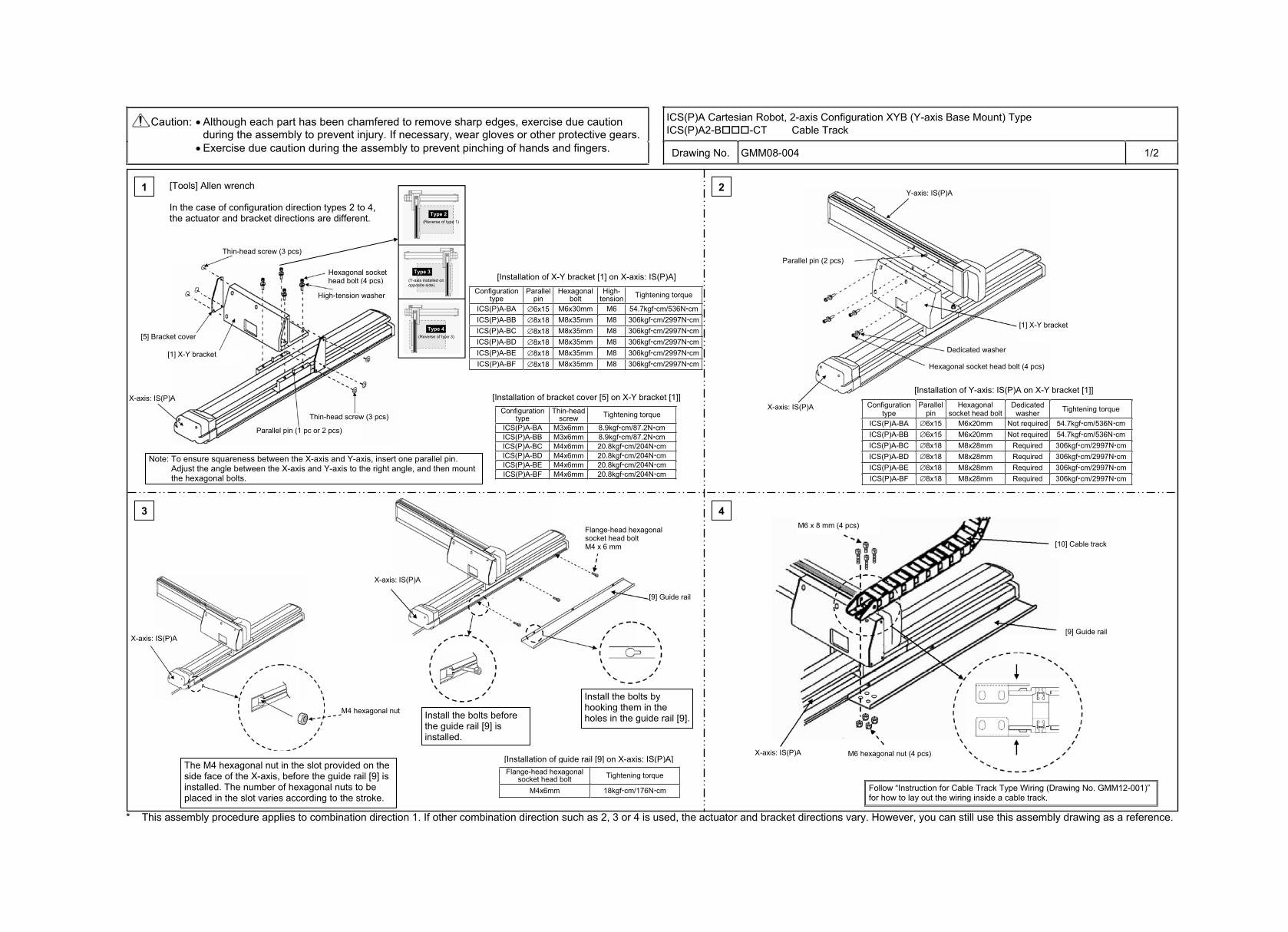
ICS(P)A Cartesian Robot, 2-axis Configuration XYB (Y-axis Base Mount) Type ICS(P)A2-B -CT Cable Track
Caution: Although each part has been chamfered to remove sharp edges, exercise due caution during the assembly to prevent injury. If necessary, wear gloves or other protective gears. Exercise due caution during the assembly to prevent pinching of hands and fingers. Drawing No. GMM08-004 1/2
* This assembly procedure applies to combination direction 1. If other combination direction such as 2, 3 or 4 is used, the actuator and bracket directions vary. However, you can still use this assembly drawing as a reference.
3 4
Flange-head hexagonal socket head bolt Tightening torque
M4x6mm 18kgf cm/176N cm
1 2
Configuration type
Parallel pin
Hexagonal bolt
High-tension Tightening torque
ICS(P)A-BA 6x15 M6x30mm M6 54.7kgf cm/536N cmICS(P)A-BB 8x18 M8x35mm M8 306kgf cm/2997N cmICS(P)A-BC 8x18 M8x35mm M8 306kgf cm/2997N cmICS(P)A-BD 8x18 M8x35mm M8 306kgf cm/2997N cmICS(P)A-BE 8x18 M8x35mm M8 306kgf cm/2997N cmICS(P)A-BF 8x18 M8x35mm M8 306kgf cm/2997N cm
Configuration type
Thin-headscrew Tightening torque
ICS(P)A-BA M3x6mm 8.9kgf cm/87.2N cmICS(P)A-BB M3x6mm 8.9kgf cm/87.2N cmICS(P)A-BC M4x6mm 20.8kgf cm/204N cmICS(P)A-BD M4x6mm 20.8kgf cm/204N cmICS(P)A-BE M4x6mm 20.8kgf cm/204N cmICS(P)A-BF M4x6mm 20.8kgf cm/204N cm
Configuration type
Parallel pin
Hexagonal socket head bolt
Dedicatedwasher Tightening torque
ICS(P)A-BA 6x15 M6x20mm Not required 54.7kgf cm/536N cmICS(P)A-BB 6x15 M6x20mm Not required 54.7kgf cm/536N cmICS(P)A-BC 8x18 M8x28mm Required 306kgf cm/2997N cmICS(P)A-BD 8x18 M8x28mm Required 306kgf cm/2997N cmICS(P)A-BE 8x18 M8x28mm Required 306kgf cm/2997N cmICS(P)A-BF 8x18 M8x28mm Required 306kgf cm/2997N cm
[Tools] Allen wrench
In the case of configuration direction types 2 to 4, the actuator and bracket directions are different.
Thin-head screw (3 pcs)
[5] Bracket cover
[1] X-Y bracket
Thin-head screw (3 pcs)
Parallel pin (1 pc or 2 pcs)
Hexagonal socket head bolt (4 pcs)
High-tension washer
Type 2 (Reverse of type 1)
Type 3 (Y-axis installed on opposite side)
Type 4 (Reverse of type 3)
X-axis: IS(P)A
Note: To ensure squareness between the X-axis and Y-axis, insert one parallel pin. Adjust the angle between the X-axis and Y-axis to the right angle, and then mount the hexagonal bolts.
Y-axis: IS(P)A
[1] X-Y bracket
Parallel pin (2 pcs)
Dedicated washer
Hexagonal socket head bolt (4 pcs)
X-axis: IS(P)A
[Installation of Y-axis: IS(P)A on X-Y bracket [1]]
M6 x 8 mm (4 pcs)
[10] Cable track
[9] Guide rail
M6 hexagonal nut (4 pcs) X-axis: IS(P)A
X-axis: IS(P)A
X-axis: IS(P)A
[9] Guide rail
The M4 hexagonal nut in the slot provided on the side face of the X-axis, before the guide rail [9] is installed. The number of hexagonal nuts to be placed in the slot varies according to the stroke.
Install the bolts before the guide rail [9] is installed.
Install the bolts by hooking them in the holes in the guide rail [9].
[Installation of guide rail [9] on X-axis: IS(P)A]
M4 hexagonal nut
Flange-head hexagonal socket head bolt M4 x 6 mm
[Installation of X-Y bracket [1] on X-axis: IS(P)A]
[Installation of bracket cover [5] on X-Y bracket [1]]
Follow “Instruction for Cable Track Type Wiring (Drawing No. GMM12-001)” for how to lay out the wiring inside a cable track.
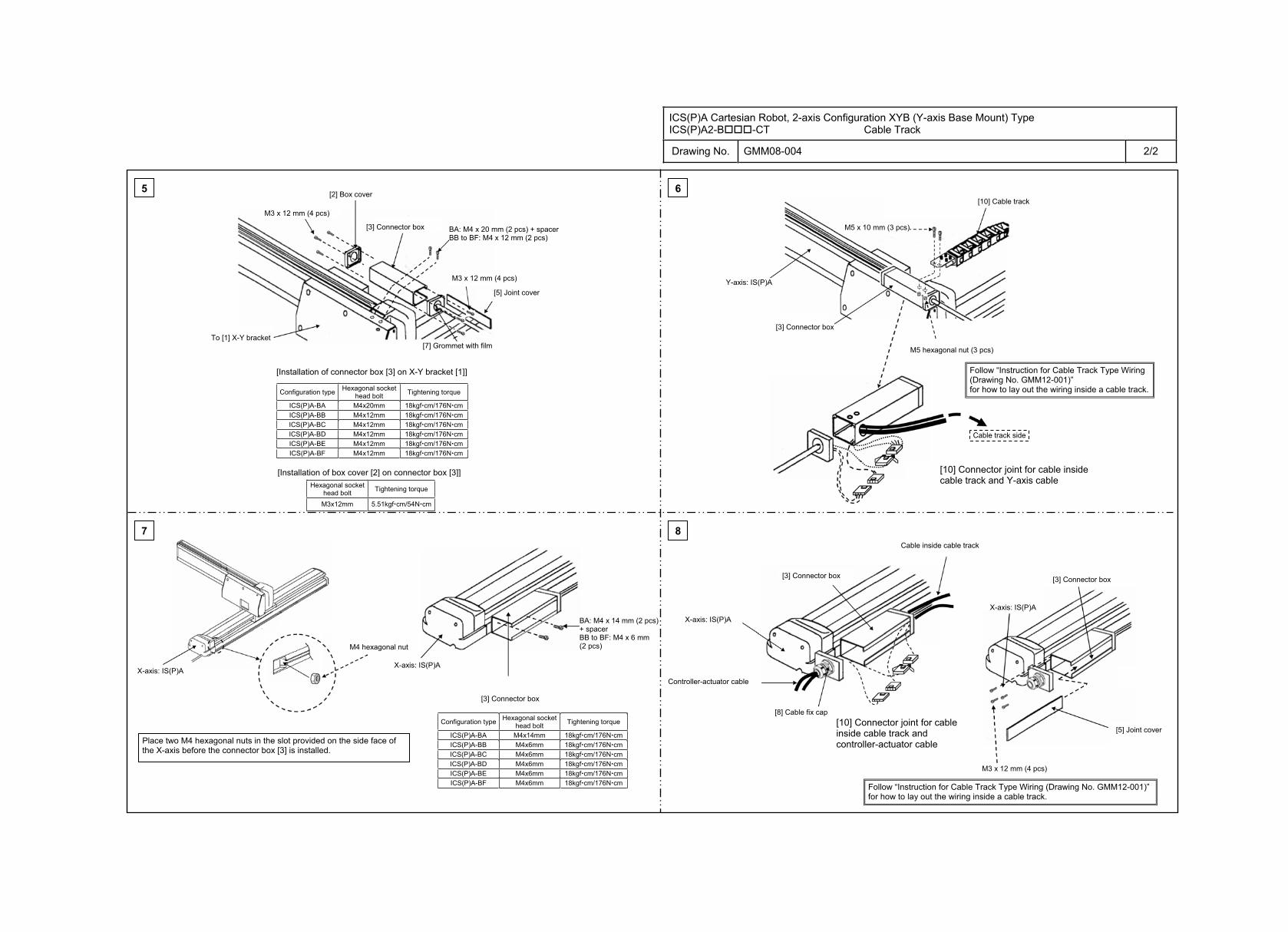
ICS(P)A Cartesian Robot, 2-axis Configuration XYB (Y-axis Base Mount) Type ICS(P)A2-B -CT Cable Track
Drawing No. GMM08-004 2/2
5 6
7 8
Hexagonal socket head bolt Tightening torque
M3x12mm 5.51kgf cm/54N cm
Configuration type Hexagonal socket head bolt Tightening torque
ICS(P)A-BA M4x20mm 18kgf cm/176N cm ICS(P)A-BB M4x12mm 18kgf cm/176N cm ICS(P)A-BC M4x12mm 18kgf cm/176N cm ICS(P)A-BD M4x12mm 18kgf cm/176N cm ICS(P)A-BE M4x12mm 18kgf cm/176N cm ICS(P)A-BF M4x12mm 18kgf cm/176N cm
Configuration type Hexagonal socket head bolt Tightening torque
ICS(P)A-BA M4x14mm 18kgf cm/176N cmICS(P)A-BB M4x6mm 18kgf cm/176N cmICS(P)A-BC M4x6mm 18kgf cm/176N cmICS(P)A-BD M4x6mm 18kgf cm/176N cmICS(P)A-BE M4x6mm 18kgf cm/176N cmICS(P)A-BF M4x6mm 18kgf cm/176N cm
M3 x 12 mm (4 pcs)
[2] Box cover
[3] Connector box M4 x 22 mm (2 pcs)
M3 x 12 mm (4 pcs)
[5] Joint cover
[7] Grommet with film To [1] X-Y bracket
[Installation of connector box [3] on X-Y bracket [1]]
[Installation of box cover [2] on connector box [3]]
BA: M4 x 20 mm (2 pcs) + spacer BB to BF: M4 x 12 mm (2 pcs)
Y-axis: IS(P)A
M5 x 10 mm (3 pcs)
[10] Cable track
[3] Connector box
Cable track side
[10] Connector joint for cable inside cable track and Y-axis cable
M5 hexagonal nut (3 pcs)
X-axis: IS(P)A
M4 hexagonal nut
X-axis: IS(P)A
[3] Connector box
Place two M4 hexagonal nuts in the slot provided on the side face of the X-axis before the connector box [3] is installed.
BA: M4 x 14 mm (2 pcs) + spacer BB to BF: M4 x 6 mm (2 pcs)
[3] Connector box
Cable inside cable track
[8] Cable fix cap
Controller-actuator cable
[3] Connector box
X-axis: IS(P)A
[5] Joint cover
M3 x 12 mm (4 pcs)
[10] Connector joint for cable inside cable track and controller-actuator cable
X-axis: IS(P)A
Follow “Instruction for Cable Track Type Wiring (Drawing No. GMM12-001)” for how to lay out the wiring inside a cable track.
Follow “Instruction for Cable Track Type Wiring (Drawing No. GMM12-001)” for how to lay out the wiring inside a cable track.
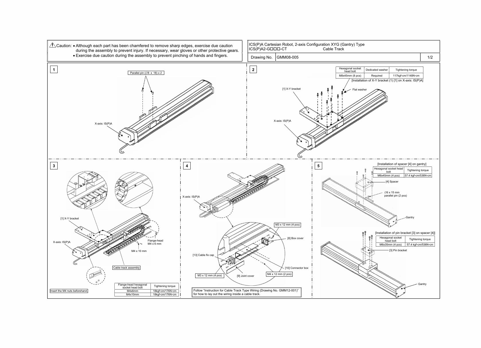
ICS(P)A Cartesian Robot, 2-axis Configuration XYG (Gantry) Type ICS(P)A2-G -CT Cable Track
Caution: Although each part has been chamfered to remove sharp edges, exercise due caution during the assembly to prevent injury. If necessary, wear gloves or other protective gears. Exercise due caution during the assembly to prevent pinching of hands and fingers. Drawing No. GMM08-005 1/2
1 2
43
Hexagonal socket head bolt Dedicated washer Tightening torque
M8x45mm (8 pcs) Required 117kgf cm/1148N cm
Flange-head hexagonal socket head bolt Tightening torque
M4x6mm 18kgf cm/176N cm M4x10mm 18kgf cm/176N cm
Hexagonal socket head bolt Tightening torque
M6x45mm (4 pcs) 57.4 kgf cm/536N cm
Hexagonal socket head bolt Tightening torque
M6x35mm (4 pcs) 57.4 kgf cm/536N cm
Parallel pin ( 8 x 18) x 2
X-axis: IS(P)A X-axis: IS(P)A
[1] X-Y bracket
[Installation of X-Y bracket (1) [1] on X-axis: IS(P)A]
[1] X-Y bracket
X-axis: IS(P)A
Cable track assembly
Insert the M4 nuts beforehand.
Flange-headM4 x 6 mm
X-axis: IS(P)A
[8] Box cover
[10] Connector box
[9] Joint cover
[13] Cable fix cap
M3 x 12 mm (4 pcs)
M3 x 12 mm (4 pcs)
M4 x 12 mm (2 pcs)
[Installation of spacer [4] on gantry]
[Installation of pin bracket [3] on spacer [4]]
[4] Spacer
Gantry
[3] Pin bracket
Gantry
6 x 15 mm parallel pin (2 pcs)
Flat washer
5
M4 x 10 mm
Follow “Instruction for Cable Track Type Wiring (Drawing No. GMM12-001)” for how to lay out the wiring inside a cable track.
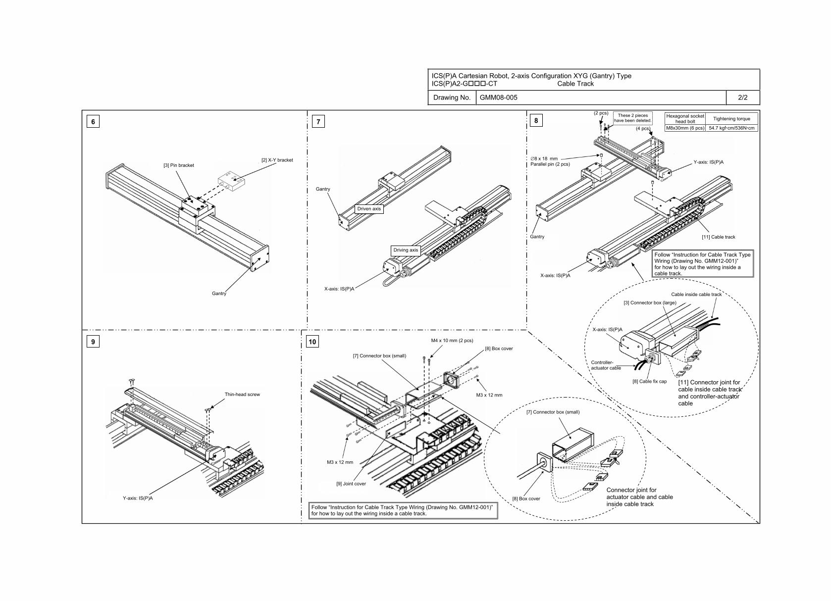
ICS(P)A Cartesian Robot, 2-axis Configuration XYG (Gantry) Type ICS(P)A2-G -CT Cable Track
Drawing No. GMM08-005 2/2
6 7
9
8
10
8 x 18 mmParallel pin (2 pcs)
Hexagonal socket head bolt Tightening torque
M8x30mm (6 pcs) 54.7 kgf cm/536N cm
[2] X-Y bracket [3] Pin bracket
Gantry
Gantry
X-axis: IS(P)A
Gantry
Y-axis: IS(P)A
[11] Cable track
X-axis: IS(P)A
Thin-head screw
Y-axis: IS(P)A
[9] Joint cover
[7] Connector box (small) [8] Box cover
[7] Connector box (small)
[8] Box cover
Connector joint for actuator cable and cable inside cable track
M4 x 10 mm (2 pcs)
Driven axis
Driving axis
(4 pcs)
(2 pcs) These 2 pieces have been deleted.
[3] Connector box (large)
Cable inside cable track
Controller-actuator cable
X-axis: IS(P)A
[8] Cable fix cap [11] Connector joint for cable inside cable track and controller-actuator cable
M3 x 12 mm
M3 x 12 mm
Follow “Instruction for Cable Track Type Wiring (Drawing No. GMM12-001)” for how to lay out the wiring inside a cable track.
Follow “Instruction for Cable Track Type Wiring (Drawing No. GMM12-001)” for how to lay out the wiring inside a cable track.
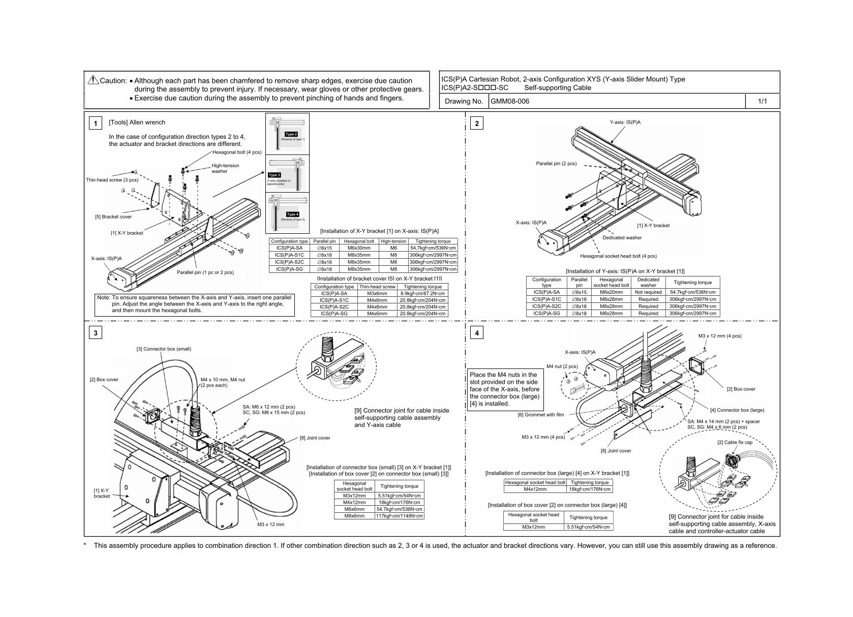
ICS(P)A Cartesian Robot, 2-axis Configuration XYS (Y-axis Slider Mount) Type ICS(P)A2-S -SC Self-supporting Cable
Caution: Although each part has been chamfered to remove sharp edges, exercise due caution during the assembly to prevent injury. If necessary, wear gloves or other protective gears. Exercise due caution during the assembly to prevent pinching of hands and fingers. Drawing No. GMM08-006 1/1
* This assembly procedure applies to combination direction 1. If other combination direction such as 2, 3 or 4 is used, the actuator and bracket directions vary. However, you can still use this assembly drawing as a reference.
2
3 4
Configuration type Parallel pin Hexagonal bolt High-tension Tightening torque ICS(P)A-SA 6x15 M6x30mm M6 54.7kgf cm/536N cm
ICS(P)A-S1C 8x18 M8x35mm M8 306kgf cm/2997N cmICS(P)A-S2C 8x18 M8x35mm M8 306kgf cm/2997N cmICS(P)A-SG 8x18 M8x35mm M8 306kgf cm/2997N cm
Configuration type Thin-head screw Tightening torque ICS(P)A-SA M3x6mm 8.9kgf cm/87.2N cm
ICS(P)A-S1C M4x6mm 20.8kgf cm/204N cmICS(P)A-S2C M4x6mm 20.8kgf cm/204N cmICS(P)A-SG M4x6mm 20.8kgf cm/204N cm
Configuration type
Parallel pin
Hexagonal socket head bolt
Dedicatedwasher Tightening torque
ICS(P)A-SA 6x15 M6x20mm Not required 54.7kgf cm/536N cmICS(P)A-S1C 8x18 M8x28mm Required 306kgf cm/2997N cmICS(P)A-S2C 8x18 M8x28mm Required 306kgf cm/2997N cmICS(P)A-SG 8x18 M8x28mm Required 306kgf cm/2997N cm
Hexagonal socket head bolt Tightening torque
M3x12mm 5.51kgf cm/54N cmM4x12mm 18kgf cm/176N cmM6x6mm 54.7kgf cm/536N cmM8x6mm 117kgf cm/1148N cm
Hexagonal socket head bolt Tightening torque M4x12mm 18kgf cm/176N cm
Hexagonal socket head bolt Tightening torque
M3x12mm 5.51kgf cm/54N cm
M4 x 10 mm, M4 nut (2 pcs each)
M3 x 12 mm
1Type 2
(Reverse of type 1)
Type 3 (Y-axis installed on opposite side)
Type 4 (Reverse of type 3)
[Tools] Allen wrench
In the case of configuration direction types 2 to 4, the actuator and bracket directions are different.
Thin-head screw (3 pcs)
[5] Bracket cover
[1] X-Y bracket
Parallel pin (1 pc or 2 pcs)
Hexagonal bolt (4 pcs)
High-tension washer
[Installation of X-Y bracket [1] on X-axis: IS(P)A]
[Installation of bracket cover [5] on X-Y bracket [1]]
Note: To ensure squareness between the X-axis and Y-axis, insert one parallel pin. Adjust the angle between the X-axis and Y-axis to the right angle, and then mount the hexagonal bolts.
X-axis: IS(P)A
Y-axis: IS(P)A
[1] X-Y bracket
Parallel pin (2 pcs)
Dedicated washer
Hexagonal socket head bolt (4 pcs)
X-axis: IS(P)A
[Installation of Y-axis: IS(P)A on X-Y bracket [1]]
[2] Box cover
[3] Connector box (small)
[8] Joint cover
[1] X-Y bracket
[Installation of connector box (small) [3] on X-Y bracket [1]][Installation of box cover [2] on connector box (small) [3]]
[9] Connector joint for cable inside self-supporting cable assembly and Y-axis cable
SA: M6 x 12 mm (2 pcs) SC, SG: M8 x 15 mm (2 pcs)
M3 x 12 mm (4 pcs)
[2] Box cover
[4] Connector box (large)
X-axis: IS(P)A
[6] Grommet with film
[2] Cable fix cap M3 x 12 mm (4 pcs)
[8] Joint cover
[Installation of connector box (large) [4] on X-Y bracket [1]]
[Installation of box cover [2] on connector box (large) [4]]
[9] Connector joint for cable inside self-supporting cable assembly, X-axis cable and controller-actuator cable
Place the M4 nuts in the slot provided on the side face of the X-axis, before the connector box (large) [4] is installed.
M4 nut (2 pcs)
SA: M4 x 14 mm (2 pcs) + spacer SC, SG: M4 x 6 mm (2 pcs)
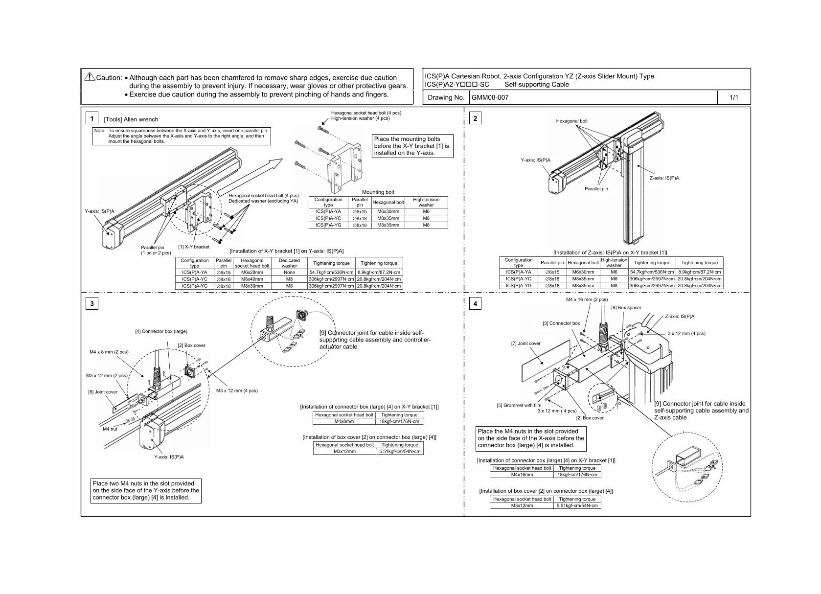
ICS(P)A Cartesian Robot, 2-axis Configuration YZ (Z-axis Slider Mount) Type ICS(P)A2-Y -SC Self-supporting Cable
Caution: Although each part has been chamfered to remove sharp edges, exercise due caution during the assembly to prevent injury. If necessary, wear gloves or other protective gears. Exercise due caution during the assembly to prevent pinching of hands and fingers. Drawing No. GMM08-007 1/1
1 2
3 4
Configuration type
Parallel pin Hexagonal bolt High-tension
washer ICS(P)A-YA 6x15 M6x30mm M6 ICS(P)A-YC 8x18 M8x35mm M8 ICS(P)A-YG 8x18 M8x35mm M8
Configuration type
Parallel pin
Hexagonal socket head bolt
Dedicatedwasher Tightening torque Tightening torque
ICS(P)A-YA 6x15 M6x28mm None 54.7kgf cm/536N cm 8.9kgf cm/87.2N cmICS(P)A-YC 8x18 M8x40mm M8 306kgf cm/2997N cm 20.8kgf cm/204N cmICS(P)A-YG 8x18 M8x30mm M8 306kgf cm/2997N cm 20.8kgf cm/204N cm
Configuration type Parallel pin Hexagonal bolt High-tension
washer Tightening torque Tightening torque
ICS(P)A-YA 6x15 M6x30mm M6 54.7kgf cm/536N cm 8.9kgf cm/87.2N cmICS(P)A-YC 8x18 M8x35mm M8 306kgf cm/2997N cm 20.8kgf cm/204N cmICS(P)A-YG 8x18 M8x35mm M8 306kgf cm/2997N cm 20.8kgf cm/204N cm
Hexagonal socket head bolt Tightening torque M4x8mm 18kgf cm/176N cm
Hexagonal socket head bolt Tightening torque M3x12mm 5.51kgf cm/54N cm
Hexagonal socket head bolt Tightening torque M4x16mm 18kgf cm/176N cm
Hexagonal socket head bolt Tightening torque M3x12mm 5.51kgf cm/54N cm
[Tools] Allen wrench
Note: To ensure squareness between the X-axis and Y-axis, insert one parallel pin. Adjust the angle between the X-axis and Y-axis to the right angle, and then mount the hexagonal bolts.
Hexagonal socket head bolt (4 pcs) Dedicated washer (excluding YA)
[1] X-Y bracket Parallel pin (1 pc or 2 pcs)
Y-axis: IS(P)A
Place the mounting bolts before the X-Y bracket [1] is installed on the Y-axis.
Mounting bolt
[Installation of X-Y bracket [1] on Y-axis: IS(P)A]
Hexagonal socket head bolt (4 pcs)High-tension washer (4 pcs)
Y-axis: IS(P)A
Hexagonal bolt
Z-axis: IS(P)A
Parallel pin
[Installation of Z-axis: IS(P)A on X-Y bracket [1]]
[4] Connector box (large)
[2] Box cover
[8] Joint cover
M4 nut
Y-axis: IS(P)A
Place two M4 nuts in the slot provided on the side face of the Y-axis before the connector box (large) [4] is installed.
[9] Connector joint for cable inside self-supporting cable assembly and controller-actuator cable
[Installation of connector box (large) [4] on X-Y bracket [1]]
[Installation of box cover [2] on connector box (large) [4]]
[Installation of connector box (large) [4] on X-Y bracket [1]]
[Installation of box cover [2] on connector box (large) [4]]
3 x 12 mm (4 pcs)
Z-axis: IS(P)A
[8] Box spacer
[3] Connector box
[7] Joint cover
[5] Grommet with film 3 x 12 mm ( 4 pcs)
[2] Box cover
[9] Connector joint for cable inside self-supporting cable assembly and Z-axis cable
Place the M4 nuts in the slot provided on the side face of the X-axis before the connector box (large) [4] is installed.
M4 x 8 mm (2 pcs)
M3 x 12 mm (2 pcs)
M3 x 12 mm (4 pcs)
M4 x 16 mm (2 pcs)
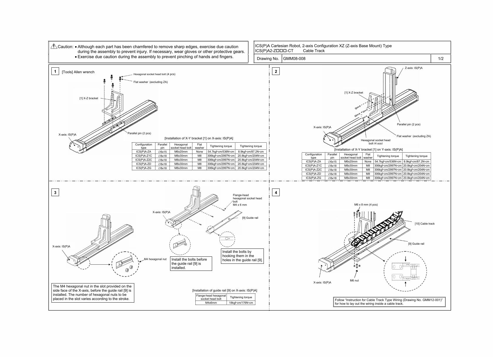
ICS(P)A Cartesian Robot, 2-axis Configuration XZ (Z-axis Base Mount) Type ICS(P)A2-Z -CT Cable Track
Caution: Although each part has been chamfered to remove sharp edges, exercise due caution during the assembly to prevent injury. If necessary, wear gloves or other protective gears. Exercise due caution during the assembly to prevent pinching of hands and fingers. Drawing No. GMM08-008 1/2
1 2
3 4
Configuration type
Parallel pin
Hexagonal socket head bolt
Flat washer Tightening torque Tightening torque
ICS(P)A-ZA 6x15 M6x20mm None 54.7kgf cm/536N cm 8.9kgf cm/87.2N cmICS(P)A-Z1C 8x18 M8x30mm M8 306kgf cm/2997N cm 20.8kgf cm/204N cmICS(P)A-Z2C 8x18 M8x30mm M8 306kgf cm/2997N cm 20.8kgf cm/204N cmICS(P)A-ZD 8x18 M8x30mm M8 306kgf cm/2997N cm 20.8kgf cm/204N cmICS(P)A-ZG 8x18 M8x30mm M8 306kgf cm/2997N cm 20.8kgf cm/204N cm
Flange-head hexagonal socket head bolt Tightening torque
M4x6mm 18kgf cm/176N cm
Configuration type
Parallel pin
Hexagonal socket head bolt
Flat washer Tightening torque Tightening torque
ICS(P)A-ZA 6x15 M6x20mm None 54.7kgf cm/536N cm 8.9kgf cm/87.2N cmICS(P)A-Z1C 8x18 M8x30mm M8 306kgf cm/2997N cm 20.8kgf cm/204N cmICS(P)A-Z2C 8x18 M8x30mm M8 306kgf cm/2997N cm 20.8kgf cm/204N cmICS(P)A-ZD 8x18 M8x30mm M8 306kgf cm/2997N cm 20.8kgf cm/204N cmICS(P)A-ZG 8x18 M8x30mm M8 306kgf cm/2997N cm 20.8kgf cm/204N cm
[Tools] Allen wrench Hexagonal socket head bolt (4 pcs)
[1] X-Z bracket
Parallel pin (2 pcs) X-axis: IS(P)A
Flat washer (excluding ZA)
[Installation of X-Y bracket [1] on X-axis: IS(P)A]
[1] X-Z bracket
Z-axis: IS(P)A
Hexagonal socket head bolt (4 pcs)
Parallel pin (2 pcs)
Flat washer (excluding ZA)
X-axis: IS(P)A
[Installation of X-Y bracket [1] on Y-axis: IS(P)A]
X-axis: IS(P)A
X-axis: IS(P)A
M4 hexagonal nut
The M4 hexagonal nut in the slot provided on the side face of the X-axis, before the guide rail [9] is installed. The number of hexagonal nuts to be placed in the slot varies according to the stroke.
[9] Guide rail
[10] Cable track
[9] Guide rail
X-axis: IS(P)A
Flange-head hexagonal socket head boltM4 x 6 mm
Install the bolts before the guide rail [9] is installed.
Install the bolts by hooking them in the holes in the guide rail [9].
[Installation of guide rail [9] on X-axis: IS(P)A]
M6 nut
M6 x 8 mm (4 pcs)
Follow “Instruction for Cable Track Type Wiring (Drawing No. GMM12-001)” for how to lay out the wiring inside a cable track.
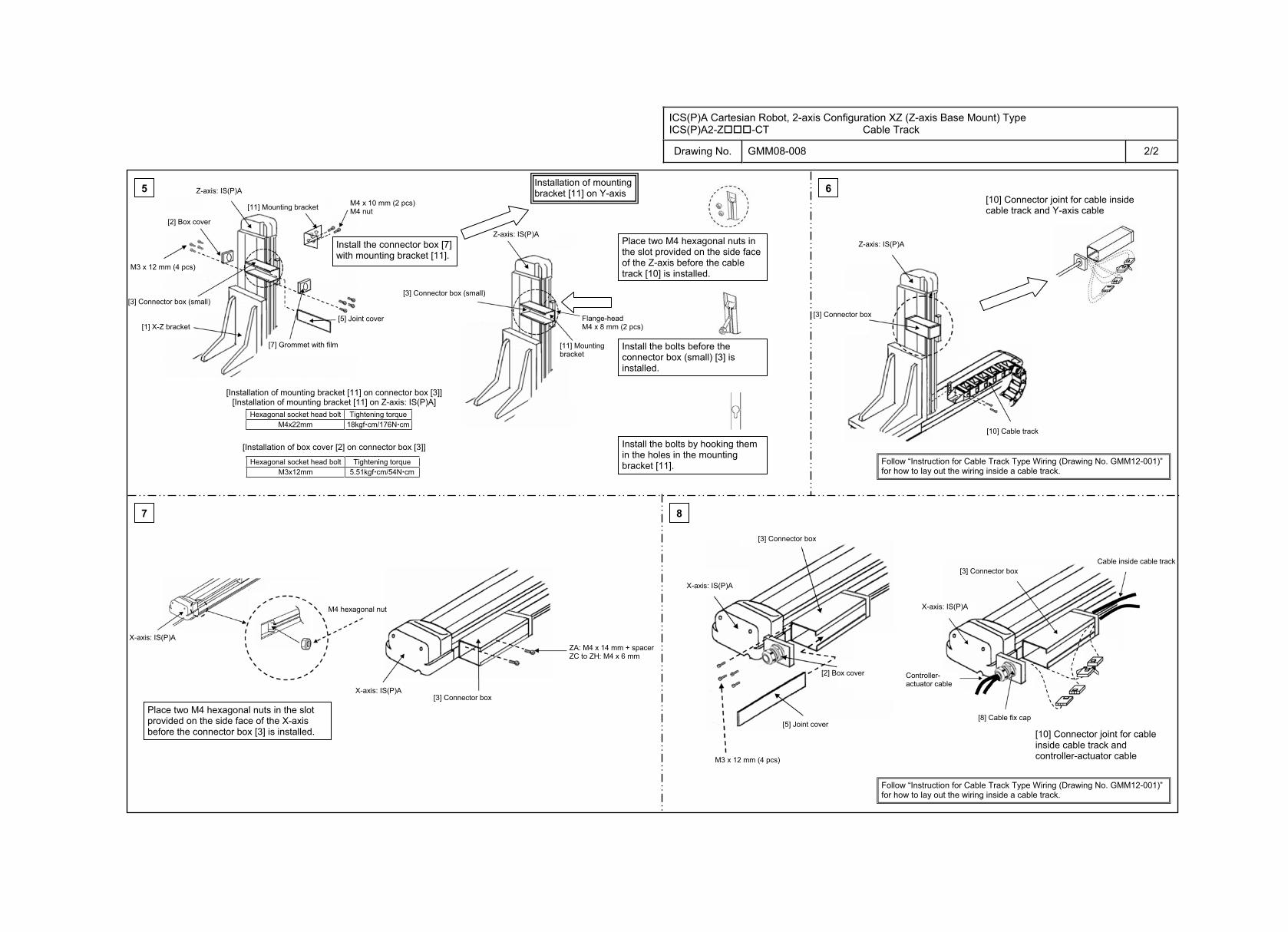
ICS(P)A Cartesian Robot, 2-axis Configuration XZ (Z-axis Base Mount) Type ICS(P)A2-Z -CT Cable Track
Drawing No. GMM08-008 2/2
6
8
Hexagonal socket head bolt Tightening torque M4x22mm 18kgf cm/176N cm
Hexagonal socket head bolt Tightening torque M3x12mm 5.51kgf cm/54N cm
Flange-headM4 x 8 mm (2 pcs)
5
7
Z-axis: IS(P)A M4 x 10 mm (2 pcs) M4 nut [11] Mounting bracket
[5] Joint cover
[7] Grommet with film
[1] X-Z bracket
[3] Connector box (small)
Installation of mounting bracket [11] on Y-axis
Z-axis: IS(P)A
[3] Connector box (small)
[11] Mounting bracket
[Installation of mounting bracket [11] on connector box [3]] [Installation of mounting bracket [11] on Z-axis: IS(P)A]
[Installation of box cover [2] on connector box [3]]
Place two M4 hexagonal nuts in the slot provided on the side face of the Z-axis before the cable track [10] is installed.
Install the bolts before the connector box (small) [3] is installed.
Install the bolts by hooking them in the holes in the mounting bracket [11].
[10] Connector joint for cable inside cable track and Y-axis cable
Z-axis: IS(P)A
[3] Connector box
[10] Cable track
X-axis: IS(P)A
M4 hexagonal nut
X-axis: IS(P)A [3] Connector box
ZA: M4 x 14 mm + spacerZC to ZH: M4 x 6 mm
M3 x 12 mm (4 pcs)
[5] Joint cover
[2] Box cover
[2] Box cover
[3] Connector box
X-axis: IS(P)A
X-axis: IS(P)A
[3] Connector box
Controller-actuator cable
Cable inside cable track
[8] Cable fix cap
[10] Connector joint for cable inside cable track and controller-actuator cable
Place two M4 hexagonal nuts in the slot provided on the side face of the X-axis before the connector box [3] is installed.
M3 x 12 mm (4 pcs)
Install the connector box [7] with mounting bracket [11].
Follow “Instruction for Cable Track Type Wiring (Drawing No. GMM12-001)” for how to lay out the wiring inside a cable track.
Follow “Instruction for Cable Track Type Wiring (Drawing No. GMM12-001)” for how to lay out the wiring inside a cable track.
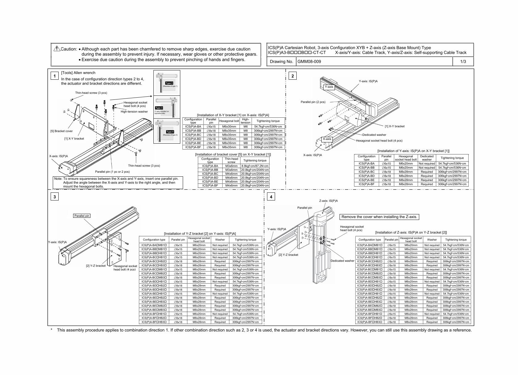
ICS(P)A Cartesian Robot, 3-axis Configuration XYB + Z-axis (Z-axis Base Mount) Type ICS(P)A3-B B -CT-CT X-axis/Y-axis: Cable Track, Y-axis/Z-axis: Self-supporting Cable Track
Caution: Although each part has been chamfered to remove sharp edges, exercise due caution during the assembly to prevent injury. If necessary, wear gloves or other protective gears. Exercise due caution during the assembly to prevent pinching of hands and fingers. Drawing No. GMM08-009 1/3
* This assembly procedure applies to combination direction 1. If other combination direction such as 2, 3 or 4 is used, the actuator and bracket directions vary. However, you can still use this assembly drawing as a reference.
Z-axis: IS(P)A
Y-axis: IS(P)A
[2] Y-Z bracket
Parallel pin
Hexagonal socket head bolt (4 pcs)
Dedicated washer
3 4
Configuration type Parallel pin Hexagonal socket head bolt Washer Tightening torque
ICS(P)A-BA MB1 6x15 M6x20mm Not required 54.7kgf cm/536N cmICS(P)A-BB MB1 6x15 M6x20mm Not required 54.7kgf cm/536N cmICS(P)A-BB HB1 6x15 M6x20mm Not required 54.7kgf cm/536N cmICS(P)A-BC HB1 6x15 M6x20mm Not required 54.7kgf cm/536N cmICS(P)A-BC HB2 8x18 M8x28mm Required 306kgf cm/2997N cmICS(P)A-BC HB3 8x18 M8x28mm Required 306kgf cm/2997N cmICS(P)A-BC MB1 6x15 M6x20mm Not required 54.7kgf cm/536N cmICS(P)A-BC MB2 8x18 M8x28mm Required 306kgf cm/2997N cmICS(P)A-BC MB3 8x18 M8x28mm Required 306kgf cm/2997N cmICS(P)A-BD HB1 6x15 M6x20mm Not required 54.7kgf cm/536N cmICS(P)A-BD HB2 8x18 M8x28mm Required 306kgf cm/2997N cmICS(P)A-BD HB3 8x18 M8x28mm Required 306kgf cm/2997N cmICS(P)A-BE HB1 6x15 M6x20mm Not required 54.7kgf cm/536N cmICS(P)A-BE HB2 8x18 M8x28mm Required 306kgf cm/2997N cmICS(P)A-BE HB3 8x18 M8x28mm Required 306kgf cm/2997N cmICS(P)A-BE MB2 8x18 M8x28mm Required 306kgf cm/2997N cmICS(P)A-BE MB3 8x18 M8x28mm Required 306kgf cm/2997N cmICS(P)A-BF HB1 6x15 M6x20mm Not required 54.7kgf cm/536N cmICS(P)A-BF HB2 8x18 M8x28mm Required 306kgf cm/2997N cmICS(P)A-BF HB3 8x18 M8x28mm Required 306kgf cm/2997N cm
1
Configuration type
Parallel pin Hexagonal bolt High-
tension Tightening torque
ICS(P)A-BA 6x15 M6x30mm M6 54.7kgf cm/536N cmICS(P)A-BB 8x18 M8x35mm M8 306kgf cm/2997N cmICS(P)A-BC 8x18 M8x35mm M8 306kgf cm/2997N cmICS(P)A-BD 8x18 M8x35mm M8 306kgf cm/2997N cmICS(P)A-BE 8x18 M8x35mm M8 306kgf cm/2997N cmICS(P)A-BF 8x18 M8x35mm M8 306kgf cm/2997N cm
Configuration type
Thin-headscrew Tightening torque
ICS(P)A-BA M3x6mm 8.9kgf cm/87.2N cmICS(P)A-BB M3x6mm 20.8kgf cm/204N cmICS(P)A-BC M4x6mm 20.8kgf cm/204N cmICS(P)A-BD M4x6mm 20.8kgf cm/204N cmICS(P)A-BE M4x6mm 20.8kgf cm/204N cmICS(P)A-BF M4x6mm 20.8kgf cm/204N cm
2
Configuration type
Parallel pin
Hexagonal socket head bolt
Dedicatedwasher Tightening torque
ICS(P)A-BA 6x15 M6x20mm Not required 54.7kgf cm/536N cmICS(P)A-BB 6x15 M6x20mm Not required 54.7kgf cm/536N cmICS(P)A-BC 8x18 M8x28mm Required 306kgf cm/2997N cmICS(P)A-BD 8x18 M8x28mm Required 306kgf cm/2997N cmICS(P)A-BE 8x18 M8x28mm Required 306kgf cm/2997N cmICS(P)A-BF 8x18 M8x28mm Required 306kgf cm/2997N cm
Hexagonal socket head bolt (4 pcs)
Dedicated washer
Hexagonal socket head bolt (4 pcs)
Configuration type Parallel pin Hexagonal socket head bolt Washer Tightening torque
ICS(P)A-BA MB1 6x15 M6x20mm Not required 54.7kgf cm/536N cmICS(P)A-BB MB1 6x15 M6x20mm Not required 54.7kgf cm/536N cmICS(P)A-BB HB1 6x15 M6x20mm Not required 54.7kgf cm/536N cmICS(P)A-BC HB1 6x15 M6x20mm Not required 54.7kgf cm/536N cmICS(P)A-BC HB2 8x18 M8x28mm Required 306kgf cm/2997N cm ICS(P)A-BC HB3 8x18 M8x28mm Required 306kgf cm/2997N cm ICS(P)A-BC MB1 6x15 M6x20mm Not required 54.7kgf cm/536N cmICS(P)A-BC MB2 8x18 M8x28mm Required 306kgf cm/2997N cm ICS(P)A-BC MB3 8x18 M8x28mm Required 306kgf cm/2997N cm ICS(P)A-BD HB1 6x15 M6x20mm Not required 54.7kgf cm/536N cmICS(P)A-BD HB2 8x18 M8x28mm Required 306kgf cm/2997N cm ICS(P)A-BD HB3 8x18 M8x28mm Required 306kgf cm/2997N cm ICS(P)A-BE HB1 6x15 M6x20mm Not required 54.7kgf cm/536N cmICS(P)A-BE HB2 8x18 M8x28mm Required 306kgf cm/2997N cm ICS(P)A-BE HB3 8x18 M8x28mm Required 306kgf cm/2997N cm ICS(P)A-BE MB2 8x18 M8x28mm Required 306kgf cm/2997N cm ICS(P)A-BE MB3 8x18 M8x28mm Required 306kgf cm/2997N cm ICS(P)A-BF HB1 6x15 M6x20mm Not required 54.7kgf cm/536N cmICS(P)A-BF HB2 8x18 M8x28mm Required 306kgf cm/2997N cm ICS(P)A-BF HB3 8x18 M8x28mm Required 306kgf cm/2997N cm
[Tools] Allen wrench In the case of configuration direction types 2 to 4, the actuator and bracket directions are different.
Thin-head screw (3 pcs)
[5] Bracket cover
[1] X-Y bracket
Thin-head screw (3 pcs)
Parallel pin (1 pc or 2 pcs)
High-tension washer [Installation of X-Y bracket [1] on X-axis: IS(P)A]
[Installation of bracket cover [5] on X-Y bracket [1]]
Note: To ensure squareness between the X-axis and Y-axis, insert one parallel pin. Adjust the angle between the X-axis and Y-axis to the right angle, and then mount the hexagonal bolts.
Y-axis: IS(P)A
[1] X-Y bracket
Parallel pin (2 pcs)
X-axis: IS(P)A[Installation of Y-axis: IS(P)A on X-Y bracket [1]]
X-axis: IS(P)A
Y-axis: IS(P)A
Parallel pin
[2] Y-Z bracket Hexagonal socket head bolt (4 pcs)
[Installation of Y-Z bracket [2] on Y-axis: IS(P)A]
Remove the cover when installing the Z-axis.
[Installation of Z-axis: IS(P)A on Y-Z bracket [2]]
Type 2 (Reverse of type 1)
Type 3 (Y-axis installed on opposite side)
Type 4 (Reverse of type 3)
X-axis
Y-axis
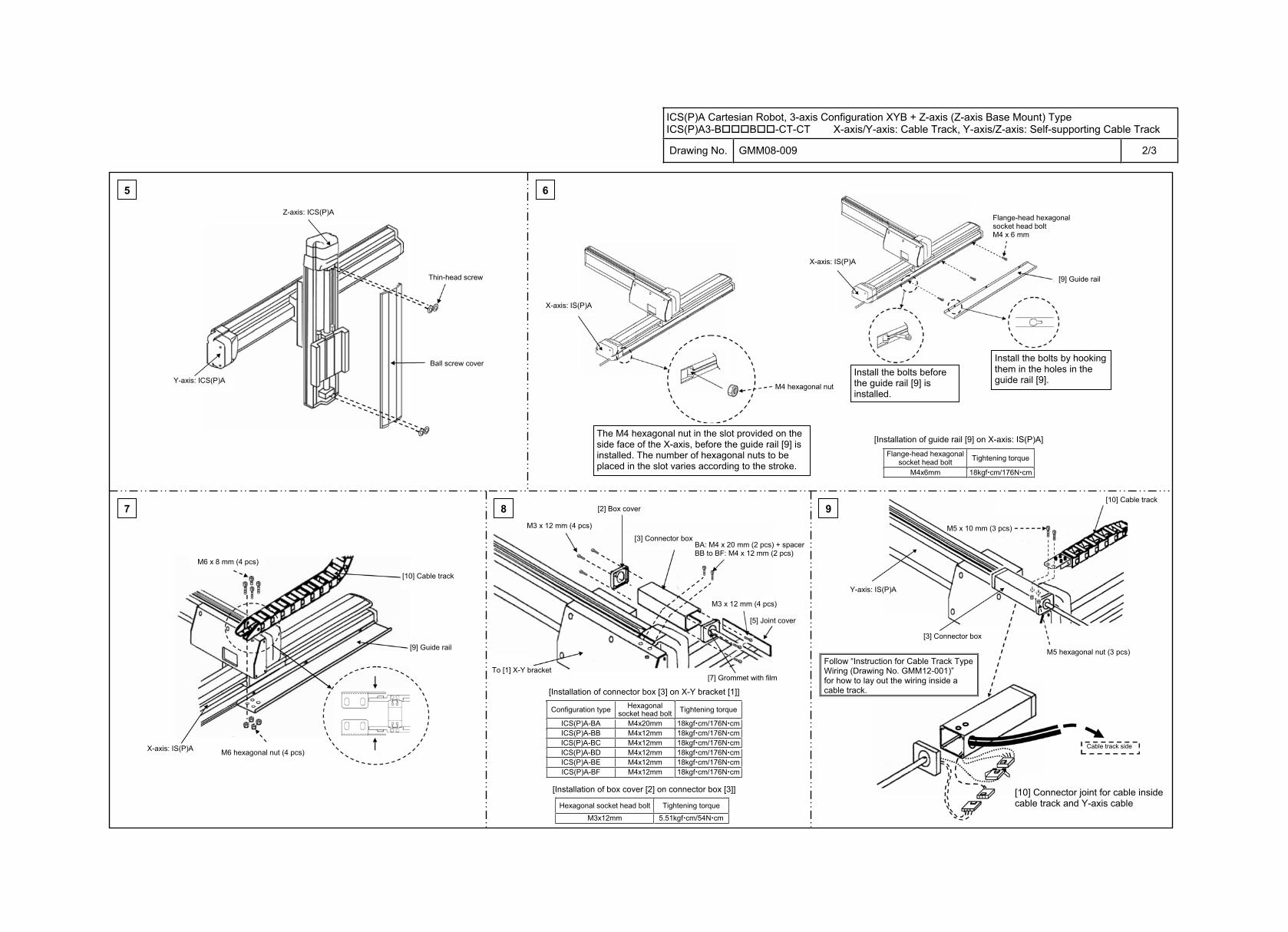
ICS(P)A Cartesian Robot, 3-axis Configuration XYB + Z-axis (Z-axis Base Mount) Type ICS(P)A3-B B -CT-CT X-axis/Y-axis: Cable Track, Y-axis/Z-axis: Self-supporting Cable Track
Drawing No. GMM08-009 2/3
5 6
7 9
Flange-head hexagonal socket head bolt Tightening torque
M4x6mm 18kgf cm/176N cm
Configuration type Hexagonal socket head bolt Tightening torque
ICS(P)A-BA M4x20mm 18kgf cm/176N cmICS(P)A-BB M4x12mm 18kgf cm/176N cmICS(P)A-BC M4x12mm 18kgf cm/176N cmICS(P)A-BD M4x12mm 18kgf cm/176N cmICS(P)A-BE M4x12mm 18kgf cm/176N cmICS(P)A-BF M4x12mm 18kgf cm/176N cm
Hexagonal socket head bolt Tightening torque
M3x12mm 5.51kgf cm/54N cm
Flange-head hexagonal socket head bolt M4 x 6 mm
Z-axis: ICS(P)A
Thin-head screw
Ball screw cover
Y-axis: ICS(P)A
X-axis: IS(P)A
M4 hexagonal nut
X-axis: IS(P)A
[9] Guide rail
The M4 hexagonal nut in the slot provided on the side face of the X-axis, before the guide rail [9] is installed. The number of hexagonal nuts to be placed in the slot varies according to the stroke.
Install the bolts before the guide rail [9] is installed.
Install the bolts by hooking them in the holes in the guide rail [9].
[Installation of guide rail [9] on X-axis: IS(P)A]
M6 x 8 mm (4 pcs)
[10] Cable track
[9] Guide rail
X-axis: IS(P)A M6 hexagonal nut (4 pcs)
M3 x 12 mm (4 pcs)
[2] Box cover
[3] Connector box
M3 x 12 mm (4 pcs)
[5] Joint cover
[7] Grommet with film To [1] X-Y bracket
[Installation of connector box [3] on X-Y bracket [1]]
[Installation of box cover [2] on connector box [3]]
BA: M4 x 20 mm (2 pcs) + spacerBB to BF: M4 x 12 mm (2 pcs)
Y-axis: IS(P)A
M5 x 10 mm (3 pcs)
[10] Cable track
[3] Connector box
Cable track side
[10] Connector joint for cable inside cable track and Y-axis cable
M5 hexagonal nut (3 pcs)
8
Follow “Instruction for Cable Track Type Wiring (Drawing No. GMM12-001)” for how to lay out the wiring inside a cable track.
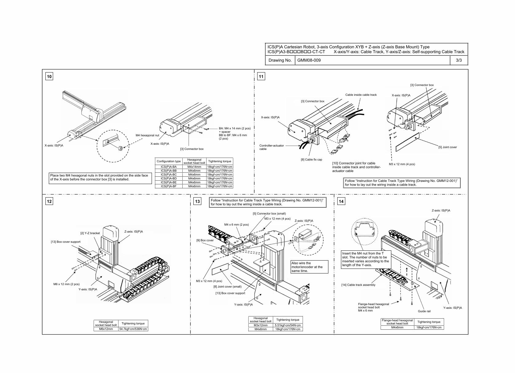
ICS(P)A Cartesian Robot, 3-axis Configuration XYB + Z-axis (Z-axis Base Mount) Type ICS(P)A3-B B -CT-CT X-axis/Y-axis: Cable Track, Y-axis/Z-axis: Self-supporting Cable Track
Drawing No. GMM08-009 3/3
Hexagonal socket head bolt Tightening torque
M3x12mm 5.51kgf cm/54N cmM4x6mm 18kgf cm/176N cm
Hexagonal socket head bolt Tightening torque
M6x12mm 54.7kgf cm/536N cm
Flange-head hexagonal socket head bolt Tightening torque
M4x6mm 18kgf cm/176N cm
10
12 13 14
11
Configuration type Hexagonal socket head bolt Tightening torque
ICS(P)A-BA M4x14mm 18kgf cm/176N cmICS(P)A-BB M4x6mm 18kgf cm/176N cmICS(P)A-BC M4x6mm 18kgf cm/176N cmICS(P)A-BD M4x6mm 18kgf cm/176N cmICS(P)A-BE M4x6mm 18kgf cm/176N cmICS(P)A-BF M4x6mm 18kgf cm/176N cm
Flange-head hexagonal socket head bolt M4 x 6 mm
M4 x 6 mm (2 pcs)
M3 x 12 mm (4 pcs)
M3 x 12 mm (4 pcs)M6 x 12 mm (2 pcs)
M3 x 12 mm (4 pcs)
X-axis: IS(P)A
M4 hexagonal nut
X-axis: IS(P)A
[3] Connector box
Place two M4 hexagonal nuts in the slot provided on the side face of the X-axis before the connector box [3] is installed.
BA: M4 x 14 mm (2 pcs) + spacer BB to BF: M4 x 6 mm (2 pcs)
[3] Connector box
Cable inside cable track
[8] Cable fix cap
Controller-actuator cable
[3] Connector box
X-axis: IS(P)A
[5] Joint cover
[10] Connector joint for cable inside cable track and controller-actuator cable
X-axis: IS(P)A
[13] Box cover support
[2] Y-Z bracket Z-axis: IS(P)A
Y-axis: IS(P)A
[5] Connector box (small)
Z-axis: IS(P)A
[8] Joint cover (small)
Y-axis: IS(P)A
[13] Box cover support
Also wire the motor/encoder at the same time.
Z-axis: IS(P)A
Insert the M4 nut from the T slot. The number of nuts to be inserted varies according to the length of the Y-axis.
[14] Cable track assembly
Guide rail
[9] Box cover
Y-axis: IS(P)A
Follow “Instruction for Cable Track Type Wiring (Drawing No. GMM12-001)” for how to lay out the wiring inside a cable track.
Follow “Instruction for Cable Track Type Wiring (Drawing No. GMM12-001)” for how to lay out the wiring inside a cable track.
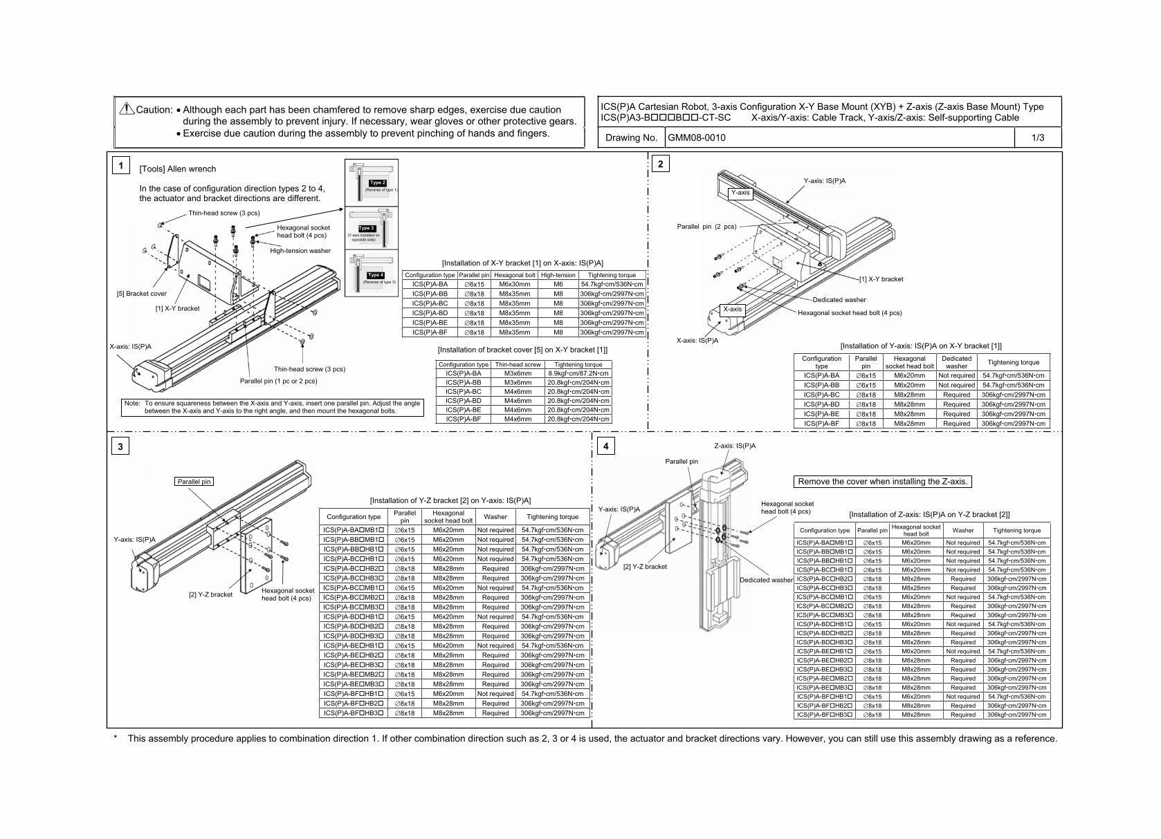
ICS(P)A Cartesian Robot, 3-axis Configuration X-Y Base Mount (XYB) + Z-axis (Z-axis Base Mount) Type ICS(P)A3-B B -CT-SC X-axis/Y-axis: Cable Track, Y-axis/Z-axis: Self-supporting Cable
Caution: Although each part has been chamfered to remove sharp edges, exercise due caution during the assembly to prevent injury. If necessary, wear gloves or other protective gears. Exercise due caution during the assembly to prevent pinching of hands and fingers. Drawing No. GMM08-0010 1/3
* This assembly procedure applies to combination direction 1. If other combination direction such as 2, 3 or 4 is used, the actuator and bracket directions vary. However, you can still use this assembly drawing as a reference.
Z-axis: IS(P)A
Y-axis: IS(P)A
[2] Y-Z bracket
Parallel pin
Hexagonal socket head bolt (4 pcs)
Dedicated washer
3 4
Configuration type Parallel pin Hexagonal socket head bolt Washer Tightening torque
ICS(P)A-BA MB1 6x15 M6x20mm Not required 54.7kgf cm/536N cmICS(P)A-BB MB1 6x15 M6x20mm Not required 54.7kgf cm/536N cmICS(P)A-BB HB1 6x15 M6x20mm Not required 54.7kgf cm/536N cmICS(P)A-BC HB1 6x15 M6x20mm Not required 54.7kgf cm/536N cmICS(P)A-BC HB2 8x18 M8x28mm Required 306kgf cm/2997N cmICS(P)A-BC HB3 8x18 M8x28mm Required 306kgf cm/2997N cmICS(P)A-BC MB1 6x15 M6x20mm Not required 54.7kgf cm/536N cmICS(P)A-BC MB2 8x18 M8x28mm Required 306kgf cm/2997N cmICS(P)A-BC MB3 8x18 M8x28mm Required 306kgf cm/2997N cmICS(P)A-BD HB1 6x15 M6x20mm Not required 54.7kgf cm/536N cmICS(P)A-BD HB2 8x18 M8x28mm Required 306kgf cm/2997N cmICS(P)A-BD HB3 8x18 M8x28mm Required 306kgf cm/2997N cmICS(P)A-BE HB1 6x15 M6x20mm Not required 54.7kgf cm/536N cmICS(P)A-BE HB2 8x18 M8x28mm Required 306kgf cm/2997N cmICS(P)A-BE HB3 8x18 M8x28mm Required 306kgf cm/2997N cmICS(P)A-BE MB2 8x18 M8x28mm Required 306kgf cm/2997N cmICS(P)A-BE MB3 8x18 M8x28mm Required 306kgf cm/2997N cmICS(P)A-BF HB1 6x15 M6x20mm Not required 54.7kgf cm/536N cmICS(P)A-BF HB2 8x18 M8x28mm Required 306kgf cm/2997N cmICS(P)A-BF HB3 8x18 M8x28mm Required 306kgf cm/2997N cm
1
Configuration type Parallel pin Hexagonal bolt High-tension Tightening torque ICS(P)A-BA 6x15 M6x30mm M6 54.7kgf cm/536N cmICS(P)A-BB 8x18 M8x35mm M8 306kgf cm/2997N cmICS(P)A-BC 8x18 M8x35mm M8 306kgf cm/2997N cmICS(P)A-BD 8x18 M8x35mm M8 306kgf cm/2997N cmICS(P)A-BE 8x18 M8x35mm M8 306kgf cm/2997N cmICS(P)A-BF 8x18 M8x35mm M8 306kgf cm/2997N cm
Configuration type Thin-head screw Tightening torque ICS(P)A-BA M3x6mm 8.9kgf cm/87.2N cmICS(P)A-BB M3x6mm 20.8kgf cm/204N cmICS(P)A-BC M4x6mm 20.8kgf cm/204N cmICS(P)A-BD M4x6mm 20.8kgf cm/204N cmICS(P)A-BE M4x6mm 20.8kgf cm/204N cmICS(P)A-BF M4x6mm 20.8kgf cm/204N cm
2
Configuration type
Parallel pin
Hexagonal socket head bolt
Dedicatedwasher Tightening torque
ICS(P)A-BA 6x15 M6x20mm Not required 54.7kgf cm/536N cmICS(P)A-BB 6x15 M6x20mm Not required 54.7kgf cm/536N cmICS(P)A-BC 8x18 M8x28mm Required 306kgf cm/2997N cmICS(P)A-BD 8x18 M8x28mm Required 306kgf cm/2997N cmICS(P)A-BE 8x18 M8x28mm Required 306kgf cm/2997N cmICS(P)A-BF 8x18 M8x28mm Required 306kgf cm/2997N cm
Hexagonal socket head bolt (4 pcs)
Dedicated washer
Hexagonal socket head bolt (4 pcs)
Parallel pin (2 pcs)
[Tools] Allen wrench
In the case of configuration direction types 2 to 4, the actuator and bracket directions are different.
Thin-head screw (3 pcs)
[5] Bracket cover
[1] X-Y bracket
Thin-head screw (3 pcs)
Parallel pin (1 pc or 2 pcs)
Type 2 (Reverse of type 1)
Type 3 (Y-axis installed on
opposite side)
Type 4 (Reverse of type 3)
[Installation of X-Y bracket [1] on X-axis: IS(P)A]
[Installation of bracket cover [5] on X-Y bracket [1]]
Note: To ensure squareness between the X-axis and Y-axis, insert one parallel pin. Adjust the angle between the X-axis and Y-axis to the right angle, and then mount the hexagonal bolts.
X-axis: IS(P)A
High-tension washer
Y-axis: IS(P)A
[1] X-Y bracket
X-axis: IS(P)A [Installation of Y-axis: IS(P)A on X-Y bracket [1]]
Y-axis: IS(P)A
Parallel pin
[2] Y-Z bracket Hexagonal socket head bolt (4 pcs)
Configuration type Parallel pin
Hexagonal socket head bolt Washer Tightening torque
ICS(P)A-BA MB1 6x15 M6x20mm Not required 54.7kgf cm/536N cmICS(P)A-BB MB1 6x15 M6x20mm Not required 54.7kgf cm/536N cmICS(P)A-BB HB1 6x15 M6x20mm Not required 54.7kgf cm/536N cmICS(P)A-BC HB1 6x15 M6x20mm Not required 54.7kgf cm/536N cmICS(P)A-BC HB2 8x18 M8x28mm Required 306kgf cm/2997N cmICS(P)A-BC HB3 8x18 M8x28mm Required 306kgf cm/2997N cmICS(P)A-BC MB1 6x15 M6x20mm Not required 54.7kgf cm/536N cmICS(P)A-BC MB2 8x18 M8x28mm Required 306kgf cm/2997N cmICS(P)A-BC MB3 8x18 M8x28mm Required 306kgf cm/2997N cmICS(P)A-BD HB1 6x15 M6x20mm Not required 54.7kgf cm/536N cmICS(P)A-BD HB2 8x18 M8x28mm Required 306kgf cm/2997N cmICS(P)A-BD HB3 8x18 M8x28mm Required 306kgf cm/2997N cmICS(P)A-BE HB1 6x15 M6x20mm Not required 54.7kgf cm/536N cmICS(P)A-BE HB2 8x18 M8x28mm Required 306kgf cm/2997N cmICS(P)A-BE HB3 8x18 M8x28mm Required 306kgf cm/2997N cmICS(P)A-BE MB2 8x18 M8x28mm Required 306kgf cm/2997N cmICS(P)A-BE MB3 8x18 M8x28mm Required 306kgf cm/2997N cmICS(P)A-BF HB1 6x15 M6x20mm Not required 54.7kgf cm/536N cmICS(P)A-BF HB2 8x18 M8x28mm Required 306kgf cm/2997N cmICS(P)A-BF HB3 8x18 M8x28mm Required 306kgf cm/2997N cm
[Installation of Y-Z bracket [2] on Y-axis: IS(P)A]
Remove the cover when installing the Z-axis.
[Installation of Z-axis: IS(P)A on Y-Z bracket [2]]
X-axis
Y-axis
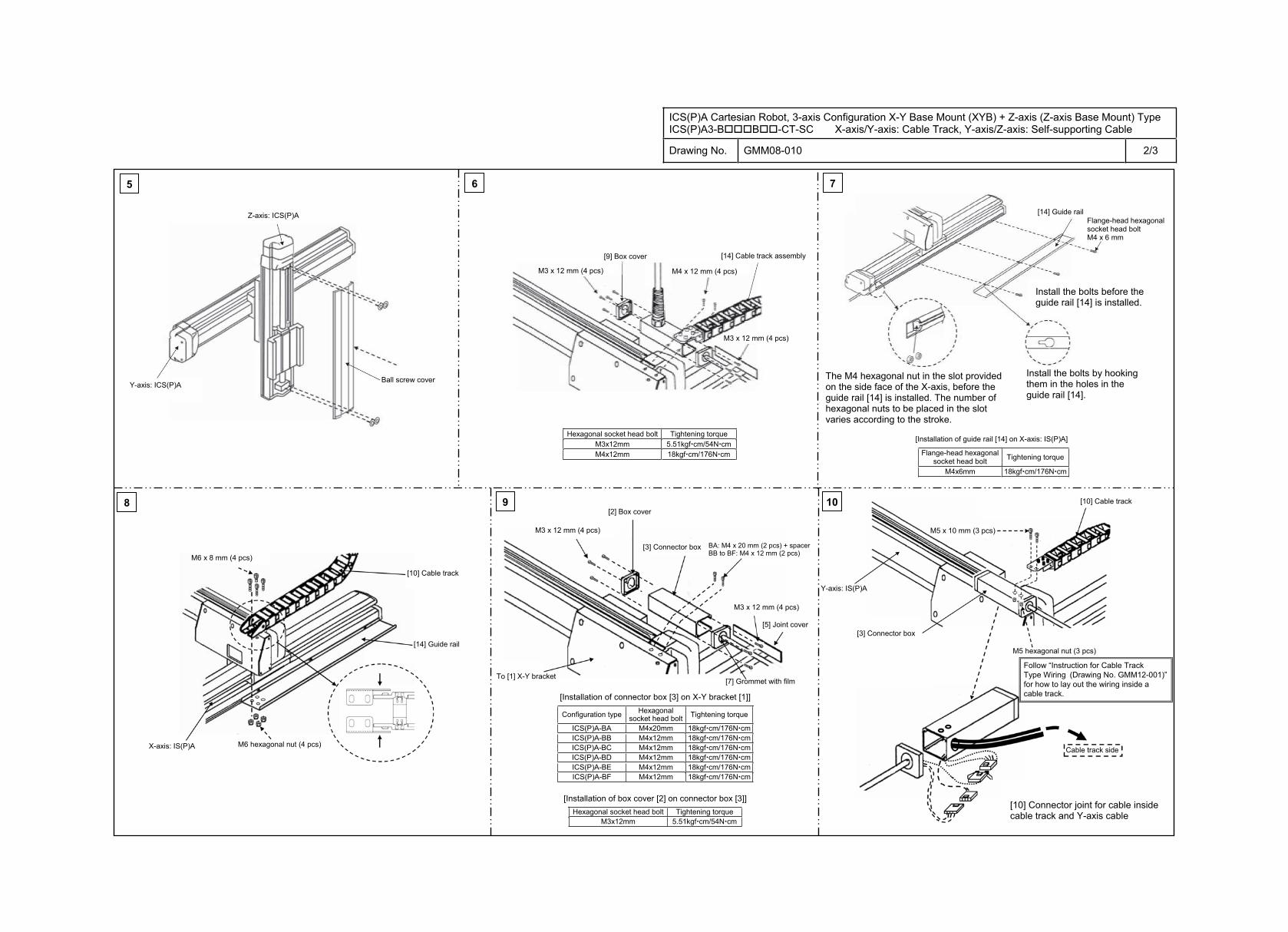
ICS(P)A Cartesian Robot, 3-axis Configuration X-Y Base Mount (XYB) + Z-axis (Z-axis Base Mount) Type ICS(P)A3-B B -CT-SC X-axis/Y-axis: Cable Track, Y-axis/Z-axis: Self-supporting Cable
Drawing No. GMM08-010 2/3
5 6 7
8 9
Flange-head hexagonal socket head bolt Tightening torque
M4x6mm 18kgf cm/176N cm
Configuration type Hexagonal socket head bolt Tightening torque
ICS(P)A-BA M4x20mm 18kgf cm/176N cmICS(P)A-BB M4x12mm 18kgf cm/176N cmICS(P)A-BC M4x12mm 18kgf cm/176N cmICS(P)A-BD M4x12mm 18kgf cm/176N cmICS(P)A-BE M4x12mm 18kgf cm/176N cmICS(P)A-BF M4x12mm 18kgf cm/176N cm
Hexagonal socket head bolt Tightening torque M3x12mm 5.51kgf cm/54N cm
Flange-head hexagonal socket head bolt M4 x 6 mm
10
[14] Guide rail
Install the bolts before the guide rail [14] is installed.
Install the bolts by hooking them in the holes in the guide rail [14].
The M4 hexagonal nut in the slot provided on the side face of the X-axis, before the guide rail [14] is installed. The number of hexagonal nuts to be placed in the slot varies according to the stroke.
[Installation of guide rail [14] on X-axis: IS(P)A]
Z-axis: ICS(P)A
Ball screw cover Y-axis: ICS(P)A
[9] Box cover
M3 x 12 mm (4 pcs) M4 x 12 mm (4 pcs)
M3 x 12 mm (4 pcs)
Hexagonal socket head bolt Tightening torque M3x12mm 5.51kgf cm/54N cmM4x12mm 18kgf cm/176N cm
[14] Cable track assembly
[10] Cable track
M6 x 8 mm (4 pcs)
X-axis: IS(P)A
[14] Guide rail
M6 hexagonal nut (4 pcs)
[2] Box cover
[3] Connector box BA: M4 x 20 mm (2 pcs) + spacer BB to BF: M4 x 12 mm (2 pcs)
To [1] X-Y bracket[7] Grommet with film
[10] Cable track
Y-axis: IS(P)A
[3] Connector box
M5 x 10 mm (3 pcs)
M5 hexagonal nut (3 pcs)
Cable track side
[Installation of connector box [3] on X-Y bracket [1]]
[Installation of box cover [2] on connector box [3]] [10] Connector joint for cable inside cable track and Y-axis cable
M3 x 12 mm (4 pcs)
[5] Joint cover
M3 x 12 mm (4 pcs)
Follow “Instruction for Cable Track Type Wiring (Drawing No. GMM12-001)” for how to lay out the wiring inside a cable track.
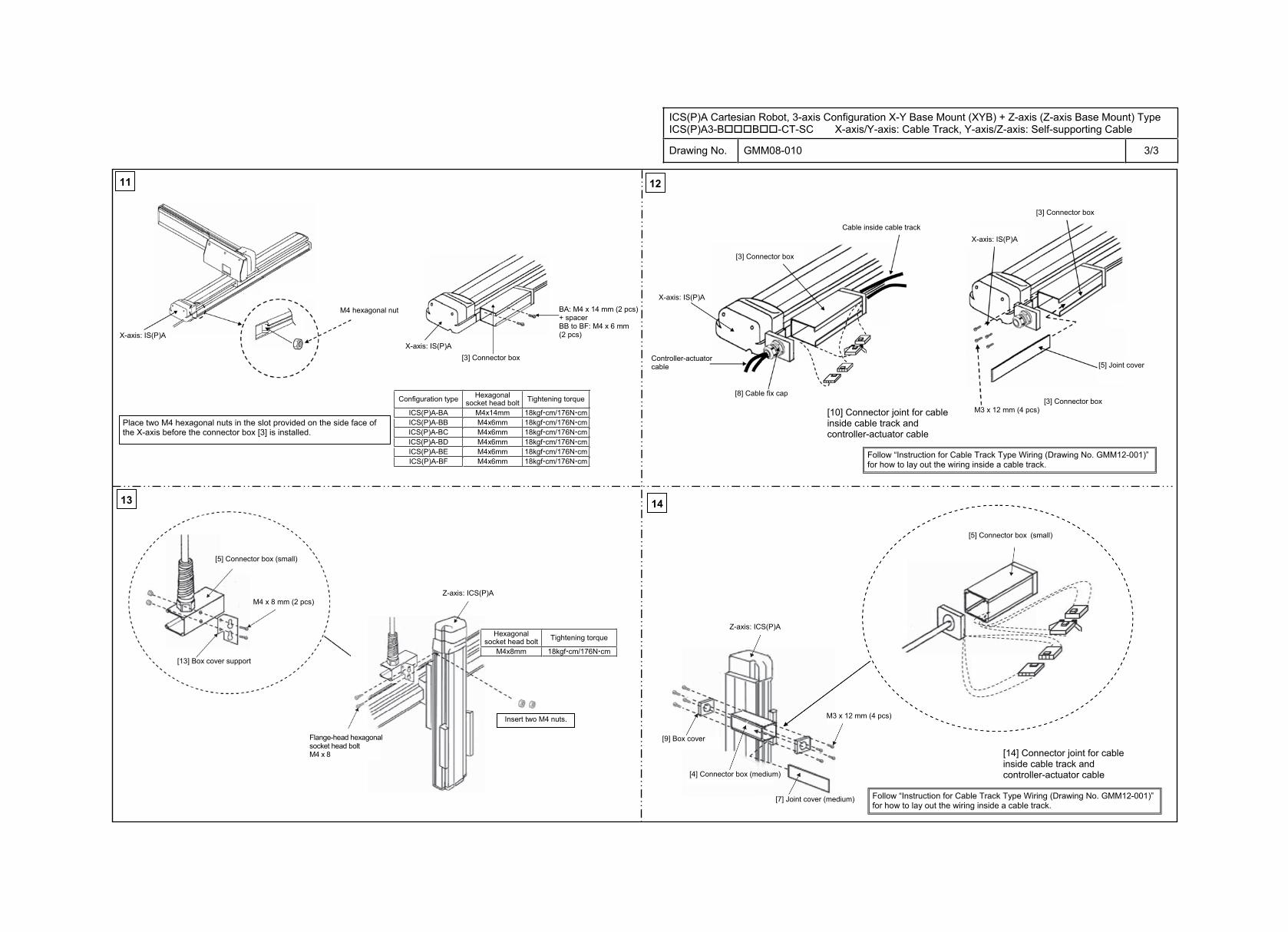
ICS(P)A Cartesian Robot, 3-axis Configuration X-Y Base Mount (XYB) + Z-axis (Z-axis Base Mount) Type ICS(P)A3-B B -CT-SC X-axis/Y-axis: Cable Track, Y-axis/Z-axis: Self-supporting Cable
Drawing No. GMM08-010 3/3
Hexagonal socket head bolt Tightening torque
M4x8mm 18kgf cm/176N cm
11
13 14
12
Configuration type Hexagonal socket head bolt Tightening torque
ICS(P)A-BA M4x14mm 18kgf cm/176N cmICS(P)A-BB M4x6mm 18kgf cm/176N cmICS(P)A-BC M4x6mm 18kgf cm/176N cmICS(P)A-BD M4x6mm 18kgf cm/176N cmICS(P)A-BE M4x6mm 18kgf cm/176N cmICS(P)A-BF M4x6mm 18kgf cm/176N cm
M4 x 8 mm (2 pcs)
M3 x 12 mm (4 pcs)
X-axis: IS(P)A
M4 hexagonal nut
X-axis: IS(P)A [3] Connector box
[5] Joint cover
[3] Connector box
X-axis: IS(P)A
[3] Connector box
X-axis: IS(P)A
Controller-actuator cable
Cable inside cable track
[8] Cable fix cap
[10] Connector joint for cable inside cable track and controller-actuator cable
[5] Connector box (small)
Z-axis: ICS(P)A
[13] Box cover support
Insert two M4 nuts.
Flange-head hexagonal socket head bolt M4 x 8 [14] Connector joint for cable
inside cable track and controller-actuator cable
Z-axis: ICS(P)A
[9] Box cover
[4] Connector box (medium)
[7] Joint cover (medium)
M3 x 12 mm (4 pcs)
Place two M4 hexagonal nuts in the slot provided on the side face of the X-axis before the connector box [3] is installed.
BA: M4 x 14 mm (2 pcs) + spacer BB to BF: M4 x 6 mm (2 pcs)
[3] Connector box
[5] Connector box (small)
Follow “Instruction for Cable Track Type Wiring (Drawing No. GMM12-001)” for how to lay out the wiring inside a cable track.
Follow “Instruction for Cable Track Type Wiring (Drawing No. GMM12-001)” for how to lay out the wiring inside a cable track.
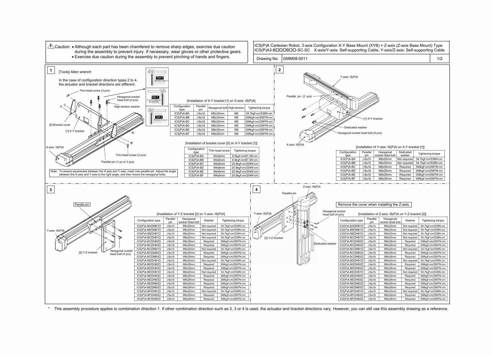
ICS(P)A Cartesian Robot, 3-axis Configuration X-Y Base Mount (XYB) + Z-axis (Z-axis Base Mount) Type ICS(P)A3-B B -SC-SC X-axis/Y-axis: Self-supporting Cable, Y-axis/Z-axis: Self-supporting Cable
Caution: Although each part has been chamfered to remove sharp edges, exercise due caution during the assembly to prevent injury. If necessary, wear gloves or other protective gears. Exercise due caution during the assembly to prevent pinching of hands and fingers. Drawing No. GMM08-0011 1/2
* This assembly procedure applies to combination direction 1. If other combination direction such as 2, 3 or 4 is used, the actuator and bracket directions vary. However, you can still use this assembly drawing as a reference.
Z-axis: IS(P)A
Y-axis: IS(P)A
[2] Y-Z bracket
Parallel pin
Hexagonal socket head bolt (4 pcs)
Dedicated washer
3 4
Configuration type Parallel pin
Hexagonal socket head bolt Washer Tightening torque
ICS(P)A-BA MB1 6x15 M6x20mm Not required 54.7kgf cm/536N cmICS(P)A-BB MB1 6x15 M6x20mm Not required 54.7kgf cm/536N cmICS(P)A-BB HB1 6x15 M6x20mm Not required 54.7kgf cm/536N cmICS(P)A-BC HB1 6x15 M6x20mm Not required 54.7kgf cm/536N cmICS(P)A-BC HB2 8x18 M8x28mm Required 306kgf cm/2997N cmICS(P)A-BC HB3 8x18 M8x28mm Required 306kgf cm/2997N cmICS(P)A-BC MB1 6x15 M6x20mm Not required 54.7kgf cm/536N cmICS(P)A-BC MB2 8x18 M8x28mm Required 306kgf cm/2997N cmICS(P)A-BC MB3 8x18 M8x28mm Required 306kgf cm/2997N cmICS(P)A-BD HB1 6x15 M6x20mm Not required 54.7kgf cm/536N cmICS(P)A-BD HB2 8x18 M8x28mm Required 306kgf cm/2997N cmICS(P)A-BD HB3 8x18 M8x28mm Required 306kgf cm/2997N cmICS(P)A-BE HB1 6x15 M6x20mm Not required 54.7kgf cm/536N cmICS(P)A-BE HB2 8x18 M8x28mm Required 306kgf cm/2997N cmICS(P)A-BE HB3 8x18 M8x28mm Required 306kgf cm/2997N cmICS(P)A-BE MB2 8x18 M8x28mm Required 306kgf cm/2997N cmICS(P)A-BE MB3 8x18 M8x28mm Required 306kgf cm/2997N cmICS(P)A-BF HB1 6x15 M6x20mm Not required 54.7kgf cm/536N cmICS(P)A-BF HB2 8x18 M8x28mm Required 306kgf cm/2997N cmICS(P)A-BF HB3 8x18 M8x28mm Required 306kgf cm/2997N cm
1
Configuration type
Parallel pin Hexagonal bolt High-tension Tightening torque
ICS(P)A-BA 6x15 M6x30mm M6 54.7kgf cm/536N cmICS(P)A-BB 8x18 M8x35mm M8 306kgf cm/2997N cmICS(P)A-BC 8x18 M8x35mm M8 306kgf cm/2997N cmICS(P)A-BD 8x18 M8x35mm M8 306kgf cm/2997N cmICS(P)A-BE 8x18 M8x35mm M8 306kgf cm/2997N cmICS(P)A-BF 8x18 M8x35mm M8 306kgf cm/2997N cm
Configuration type Thin-head screw Tightening torque
ICS(P)A-BA M3x6mm 8.9kgf cm/87.2N cmICS(P)A-BB M3x6mm 8.9kgf cm/87.2N cmICS(P)A-BC M4x6mm 20.8kgf cm/204N cmICS(P)A-BD M4x6mm 20.8kgf cm/204N cmICS(P)A-BE M4x6mm 20.8kgf cm/204N cmICS(P)A-BF M4x6mm 20.8kgf cm/204N cm
2
Configuration type
Parallel pin
Hexagonal socket head bolt
Dedicatedwasher Tightening torque
ICS(P)A-BA 6x15 M6x20mm Not required 54.7kgf cm/536N cmICS(P)A-BB 6x15 M6x20mm Not required 54.7kgf cm/536N cmICS(P)A-BC 8x18 M8x28mm Required 306kgf cm/2997N cmICS(P)A-BD 8x18 M8x28mm Required 306kgf cm/2997N cmICS(P)A-BE 8x18 M8x28mm Required 306kgf cm/2997N cmICS(P)A-BF 8x18 M8x28mm Required 306kgf cm/2997N cm
Hexagonal socket head bolt (4 pcs)
Dedicated washer
Hexagonal socket head bolt (4 pcs)
Parallel pin (2 pcs)
Configuration type Parallel pin
Hexagonal socket head bolt Washer Tightening torque
ICS(P)A-BA MB1 6x15 M6x20mm Not required 54.7kgf cm/536N cmICS(P)A-BB MB1 6x15 M6x20mm Not required 54.7kgf cm/536N cmICS(P)A-BB HB1 6x15 M6x20mm Not required 54.7kgf cm/536N cmICS(P)A-BC HB1 6x15 M6x20mm Not required 54.7kgf cm/536N cmICS(P)A-BC HB2 8x18 M8x28mm Required 306kgf cm/2997N cm ICS(P)A-BC HB3 8x18 M8x28mm Required 306kgf cm/2997N cm ICS(P)A-BC MB1 6x15 M6x20mm Not required 54.7kgf cm/536N cmICS(P)A-BC MB2 8x18 M8x28mm Required 306kgf cm/2997N cm ICS(P)A-BC MB3 8x18 M8x28mm Required 306kgf cm/2997N cm ICS(P)A-BD HB1 6x15 M6x20mm Not required 54.7kgf cm/536N cmICS(P)A-BD HB2 8x18 M8x28mm Required 306kgf cm/2997N cm ICS(P)A-BD HB3 8x18 M8x28mm Required 306kgf cm/2997N cm ICS(P)A-BE HB1 6x15 M6x20mm Not required 54.7kgf cm/536N cmICS(P)A-BE HB2 8x18 M8x28mm Required 306kgf cm/2997N cm ICS(P)A-BE HB3 8x18 M8x28mm Required 306kgf cm/2997N cm ICS(P)A-BE MB2 8x18 M8x28mm Required 306kgf cm/2997N cm ICS(P)A-BE MB3 8x18 M8x28mm Required 306kgf cm/2997N cm ICS(P)A-BF HB1 6x15 M6x20mm Not required 54.7kgf cm/536N cmICS(P)A-BF HB2 8x18 M8x28mm Required 306kgf cm/2997N cm ICS(P)A-BF HB3 8x18 M8x28mm Required 306kgf cm/2997N cm
[Tools] Allen wrench
In the case of configuration direction types 2 to 4, the actuator and bracket directions are different.
Thin-head screw (3 pcs)
[5] Bracket cover
[1] X-Y bracket
Thin-head screw (3 pcs)
Parallel pin (1 pc or 2 pcs)
Type 2 (Reverse of type 1)
Type 3 (Y-axis installed on
opposite side)
Type 4 (Reverse of type 3)
[Installation of X-Y bracket [1] on X-axis: IS(P)A]
[Installation of bracket cover [5] on X-Y bracket [1]]
Note: To ensure squareness between the X-axis and Y-axis, insert one parallel pin. Adjust the angle between the X-axis and Y-axis to the right angle, and then mount the hexagonal bolts.
X-axis: IS(P)A
High-tension washer
Y-axis: IS(P)A
[1] X-Y bracket
X-axis: IS(P)A [Installation of Y-axis: IS(P)A on X-Y bracket [1]]
Y-axis: IS(P)A
Parallel pin
[2] Y-Z bracket Hexagonal socket head bolt (4 pcs)
[Installation of Y-Z bracket [2] on Y-axis: IS(P)A]
Remove the cover when installing the Z-axis.
[Installation of Z-axis: IS(P)A on Y-Z bracket [2]]
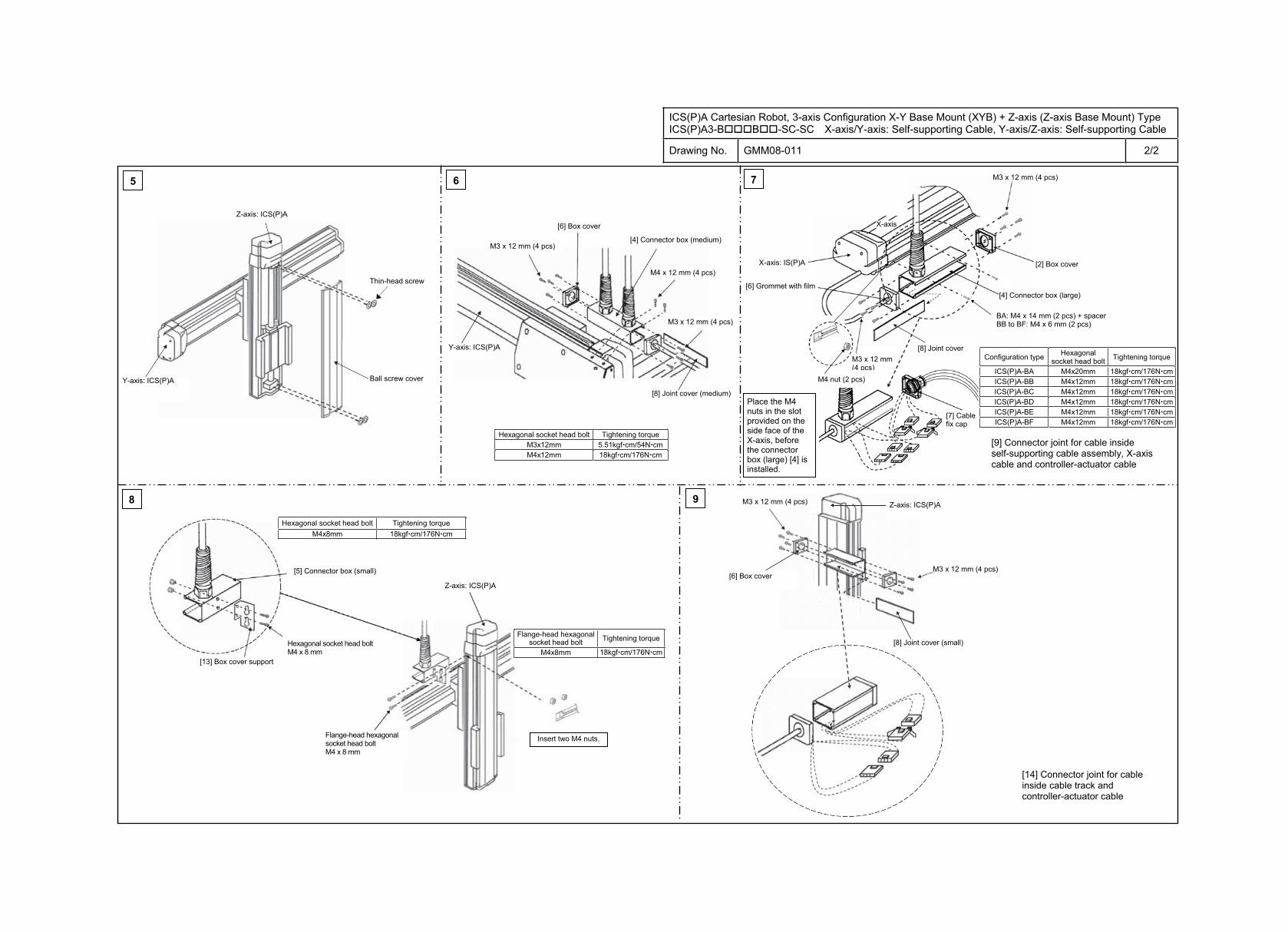
ICS(P)A Cartesian Robot, 3-axis Configuration X-Y Base Mount (XYB) + Z-axis (Z-axis Base Mount) Type ICS(P)A3-B B -SC-SC X-axis/Y-axis: Self-supporting Cable, Y-axis/Z-axis: Self-supporting Cable
Drawing No. GMM08-011 2/2
5 6 7
8 9
Configuration type Hexagonal socket head bolt Tightening torque
ICS(P)A-BA M4x20mm 18kgf cm/176N cmICS(P)A-BB M4x12mm 18kgf cm/176N cmICS(P)A-BC M4x12mm 18kgf cm/176N cmICS(P)A-BD M4x12mm 18kgf cm/176N cmICS(P)A-BE M4x12mm 18kgf cm/176N cmICS(P)A-BF M4x12mm 18kgf cm/176N cm
Z-axis: ICS(P)A
Ball screw cover Y-axis: ICS(P)A
[6] Box cover
M3 x 12 mm (4 pcs)
M4 x 12 mm (4 pcs)
M3 x 12 mm (4 pcs)
Hexagonal socket head bolt Tightening torque M3x12mm 5.51kgf cm/54N cmM4x12mm 18kgf cm/176N cm
M3 x 12 mm (4 pcs)
[6] Box cover
[4] Connector box (medium)
Flange-head hexagonal socket head bolt Tightening torque
M4x8mm 18kgf cm/176N cm
Hexagonal socket head bolt Tightening torque M4x8mm 18kgf cm/176N cm
Y-axis: ICS(P)A
X-axis: IS(P)A
X-axis
[6] Grommet with film
M3 x 12 mm (4 pcs)
[2] Box cover
[4] Connector box (large)
[8] Joint cover
M4 nut (2 pcs)
[8] Joint cover (medium)
[9] Connector joint for cable inside self-supporting cable assembly, X-axis cable and controller-actuator cable
[5] Connector box (small)
Hexagonal socket head bolt M4 x 8 mm
Flange-head hexagonal socket head bolt M4 x 8 mm
Z-axis: ICS(P)A
[13] Box cover support
Insert two M4 nuts.
Z-axis: ICS(P)A
[8] Joint cover (small)
M3 x 12 mm (4 pcs)
[14] Connector joint for cable inside cable track and controller-actuator cable
[7] Cable fix cap
BA: M4 x 14 mm (2 pcs) + spacer BB to BF: M4 x 6 mm (2 pcs)
Thin-head screw
Place the M4 nuts in the slot provided on the side face of the X-axis, before the connector box (large) [4] is installed.
M3 x 12 mm (4 pcs)
ICS(P)A Cartesian Robot, 3-axis Configuration X-Y Base Mount (XYB) + Z-axis (Z-axis Slider Mount) Type ICS(P)A3-B S -SC-SC X-axis/Y-axis: Self-supporting Cable, Y-axis/Z-axis: Self-supporting Cable
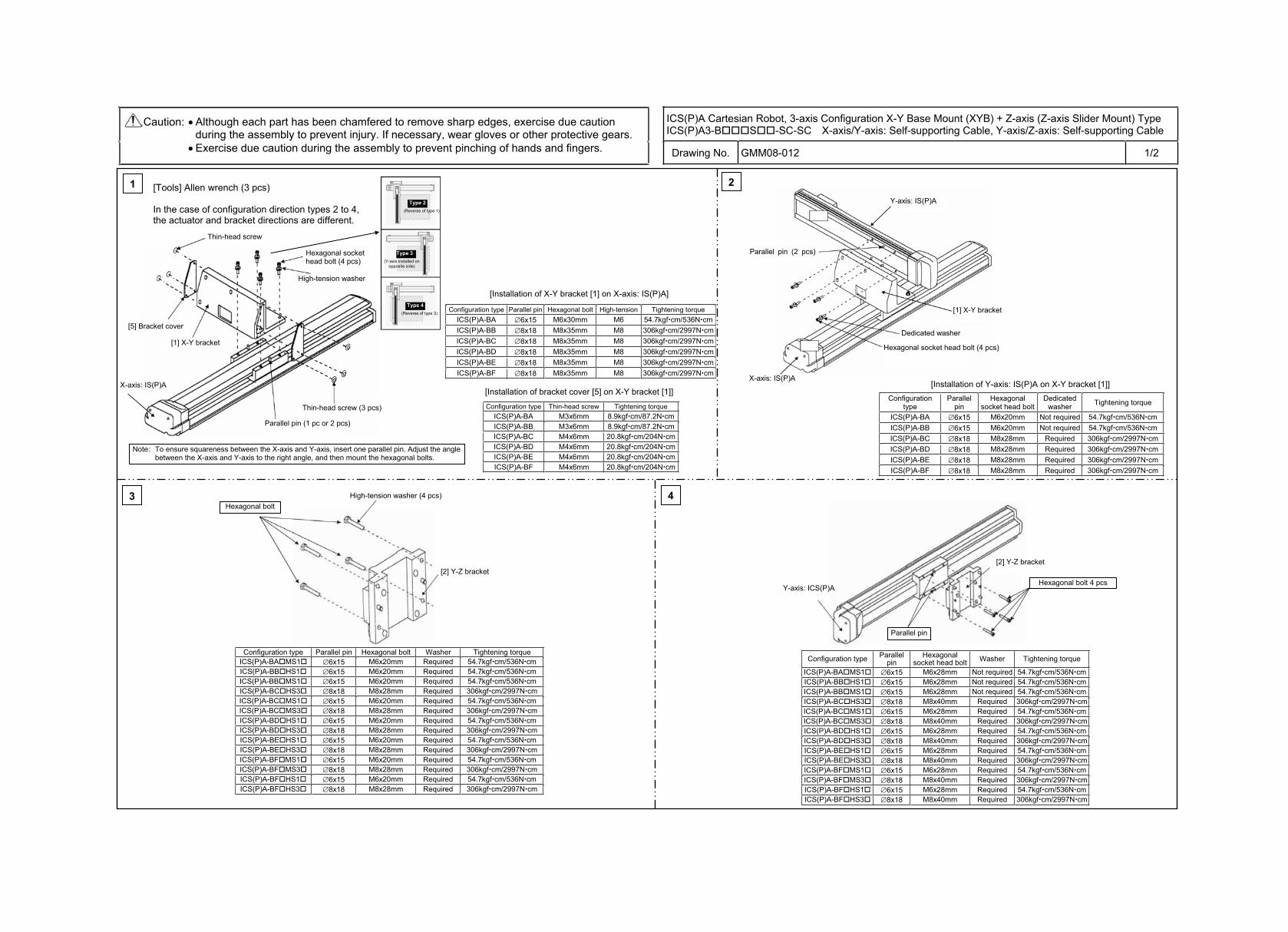
Caution: Although each part has been chamfered to remove sharp edges, exercise due caution during the assembly to prevent injury. If necessary, wear gloves or other protective gears. Exercise due caution during the assembly to prevent pinching of hands and fingers. Drawing No. GMM08-012 1/2
3 4
Configuration type Parallel pin
Hexagonal socket head bolt Washer Tightening torque
ICS(P)A-BA MS1 6x15 M6x28mm Not required 54.7kgf cm/536N cmICS(P)A-BB HS1 6x15 M6x28mm Not required 54.7kgf cm/536N cmICS(P)A-BB MS1 6x15 M6x28mm Not required 54.7kgf cm/536N cmICS(P)A-BC HS3 8x18 M8x40mm Required 306kgf cm/2997N cmICS(P)A-BC MS1 6x15 M6x28mm Required 54.7kgf cm/536N cmICS(P)A-BC MS3 8x18 M8x40mm Required 306kgf cm/2997N cmICS(P)A-BD HS1 6x15 M6x28mm Required 54.7kgf cm/536N cmICS(P)A-BD HS3 8x18 M8x40mm Required 306kgf cm/2997N cmICS(P)A-BE HS1 6x15 M6x28mm Required 54.7kgf cm/536N cmICS(P)A-BE HS3 8x18 M8x40mm Required 306kgf cm/2997N cmICS(P)A-BF MS1 6x15 M6x28mm Required 54.7kgf cm/536N cmICS(P)A-BF MS3 8x18 M8x40mm Required 306kgf cm/2997N cmICS(P)A-BF HS1 6x15 M6x28mm Required 54.7kgf cm/536N cmICS(P)A-BF HS3 8x18 M8x40mm Required 306kgf cm/2997N cm
1
Configuration type Parallel pin Hexagonal bolt High-tension Tightening torque ICS(P)A-BA 6x15 M6x30mm M6 54.7kgf cm/536N cmICS(P)A-BB 8x18 M8x35mm M8 306kgf cm/2997N cmICS(P)A-BC 8x18 M8x35mm M8 306kgf cm/2997N cmICS(P)A-BD 8x18 M8x35mm M8 306kgf cm/2997N cmICS(P)A-BE 8x18 M8x35mm M8 306kgf cm/2997N cmICS(P)A-BF 8x18 M8x35mm M8 306kgf cm/2997N cm
Configuration type Thin-head screw Tightening torque ICS(P)A-BA M3x6mm 8.9kgf cm/87.2N cmICS(P)A-BB M3x6mm 8.9kgf cm/87.2N cmICS(P)A-BC M4x6mm 20.8kgf cm/204N cmICS(P)A-BD M4x6mm 20.8kgf cm/204N cmICS(P)A-BE M4x6mm 20.8kgf cm/204N cmICS(P)A-BF M4x6mm 20.8kgf cm/204N cm
2
Configuration type
Parallel pin
Hexagonal socket head bolt
Dedicatedwasher Tightening torque
ICS(P)A-BA 6x15 M6x20mm Not required 54.7kgf cm/536N cmICS(P)A-BB 6x15 M6x20mm Not required 54.7kgf cm/536N cmICS(P)A-BC 8x18 M8x28mm Required 306kgf cm/2997N cmICS(P)A-BD 8x18 M8x28mm Required 306kgf cm/2997N cmICS(P)A-BE 8x18 M8x28mm Required 306kgf cm/2997N cmICS(P)A-BF 8x18 M8x28mm Required 306kgf cm/2997N cm
Hexagonal socket head bolt (4 pcs)
Dedicated washer
Hexagonal socket head bolt (4 pcs)
Parallel pin (2 pcs)
Configuration type Parallel pin Hexagonal bolt Washer Tightening torque ICS(P)A-BA MS1 6x15 M6x20mm Required 54.7kgf cm/536N cmICS(P)A-BB HS1 6x15 M6x20mm Required 54.7kgf cm/536N cmICS(P)A-BB MS1 6x15 M6x20mm Required 54.7kgf cm/536N cmICS(P)A-BC HS3 8x18 M8x28mm Required 306kgf cm/2997N cmICS(P)A-BC MS1 6x15 M6x20mm Required 54.7kgf cm/536N cmICS(P)A-BC MS3 8x18 M8x28mm Required 306kgf cm/2997N cmICS(P)A-BD HS1 6x15 M6x20mm Required 54.7kgf cm/536N cmICS(P)A-BD HS3 8x18 M8x28mm Required 306kgf cm/2997N cmICS(P)A-BE HS1 6x15 M6x20mm Required 54.7kgf cm/536N cmICS(P)A-BE HS3 8x18 M8x28mm Required 306kgf cm/2997N cmICS(P)A-BF MS1 6x15 M6x20mm Required 54.7kgf cm/536N cmICS(P)A-BF MS3 8x18 M8x28mm Required 306kgf cm/2997N cmICS(P)A-BF HS1 6x15 M6x20mm Required 54.7kgf cm/536N cmICS(P)A-BF HS3 8x18 M8x28mm Required 306kgf cm/2997N cm
[Tools] Allen wrench (3 pcs)
In the case of configuration direction types 2 to 4, the actuator and bracket directions are different.
Thin-head screw
[5] Bracket cover
[1] X-Y bracket
Thin-head screw (3 pcs)
Parallel pin (1 pc or 2 pcs)
Type 2 (Reverse of type 1)
Type 3 (Y-axis installed on
opposite side)
Type 4 (Reverse of type 3)
[Installation of X-Y bracket [1] on X-axis: IS(P)A]
[Installation of bracket cover [5] on X-Y bracket [1]]
Note: To ensure squareness between the X-axis and Y-axis, insert one parallel pin. Adjust the angle between the X-axis and Y-axis to the right angle, and then mount the hexagonal bolts.
X-axis: IS(P)A
High-tension washer
Y-axis: IS(P)A
[1] X-Y bracket
X-axis: IS(P)A [Installation of Y-axis: IS(P)A on X-Y bracket [1]]
Hexagonal bolt
[2] Y-Z bracket
Y-axis: ICS(P)A
[2] Y-Z bracket
Parallel pin
High-tension washer (4 pcs)
Hexagonal bolt 4 pcs
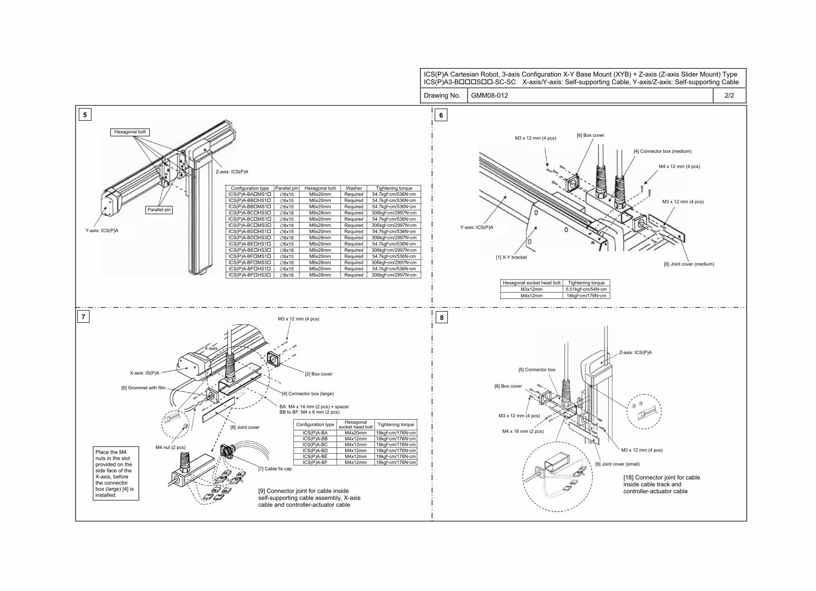
ICS(P)A Cartesian Robot, 3-axis Configuration X-Y Base Mount (XYB) + Z-axis (Z-axis Slider Mount) Type ICS(P)A3-B S -SC-SC X-axis/Y-axis: Self-supporting Cable, Y-axis/Z-axis: Self-supporting Cable
Drawing No. GMM08-012 2/2
5 6
7 8
Y-axis: ICS(P)A
M3 x 12 mm (4 pcs)
Hexagonal socket head bolt Tightening torque M3x12mm 5.51kgf cm/54N cmM4x12mm 18kgf cm/176N cm
[4] Connector box (medium)
[5] Connector box
Configuration type Parallel pin Hexagonal bolt Washer Tightening torque ICS(P)A-BA MS1 6x15 M6x20mm Required 54.7kgf cm/536N cmICS(P)A-BB HS1 6x15 M6x20mm Required 54.7kgf cm/536N cmICS(P)A-BB MS1 6x15 M6x20mm Required 54.7kgf cm/536N cmICS(P)A-BC HS3 8x18 M8x28mm Required 306kgf cm/2997N cmICS(P)A-BC MS1 6x15 M6x20mm Required 54.7kgf cm/536N cmICS(P)A-BC MS3 8x18 M8x28mm Required 306kgf cm/2997N cmICS(P)A-BD HS1 6x15 M6x20mm Required 54.7kgf cm/536N cmICS(P)A-BD HS3 8x18 M8x28mm Required 306kgf cm/2997N cmICS(P)A-BE HS1 6x15 M6x20mm Required 54.7kgf cm/536N cmICS(P)A-BE HS3 8x18 M8x28mm Required 306kgf cm/2997N cmICS(P)A-BF MS1 6x15 M6x20mm Required 54.7kgf cm/536N cmICS(P)A-BF MS3 8x18 M8x28mm Required 306kgf cm/2997N cmICS(P)A-BF HS1 6x15 M6x20mm Required 54.7kgf cm/536N cmICS(P)A-BF HS3 8x18 M8x28mm Required 306kgf cm/2997N cm
[8] Joint cover (medium)
Z-axis: ICS(P)A
Hexagonal bolt
Parallel pin
M4 x 12 mm (4 pcs)
[6] Box cover
Y-axis: ICS(P)A
[1] X-Y bracket
M3 x 12 mm (4 pcs)
Configuration type Hexagonal socket head bolt Tightening torque
ICS(P)A-BA M4x20mm 18kgf cm/176N cmICS(P)A-BB M4x12mm 18kgf cm/176N cmICS(P)A-BC M4x12mm 18kgf cm/176N cmICS(P)A-BD M4x12mm 18kgf cm/176N cmICS(P)A-BE M4x12mm 18kgf cm/176N cmICS(P)A-BF M4x12mm 18kgf cm/176N cm
X-axis: IS(P)A
[6] Grommet with film
M3 x 12 mm (4 pcs)
[2] Box cover
[4] Connector box (large)
[8] Joint cover
M4 nut (2 pcs)
[9] Connector joint for cable inside self-supporting cable assembly, X-axis cable and controller-actuator cable
[7] Cable fix cap
M3 x 12 mm (4 pcs)
[6] Box cover
M4 x 16 mm (2 pcs)
Z-axis: ICS(P)A
M3 x 12 mm (4 pcs)
[18] Connector joint for cable inside cable track and controller-actuator cable
[9] Joint cover (small)
BA: M4 x 14 mm (2 pcs) + spacer BB to BF: M4 x 6 mm (2 pcs)
Place the M4 nuts in the slot provided on the side face of the X-axis, before the connector box (large) [4] is installed.
X-axis
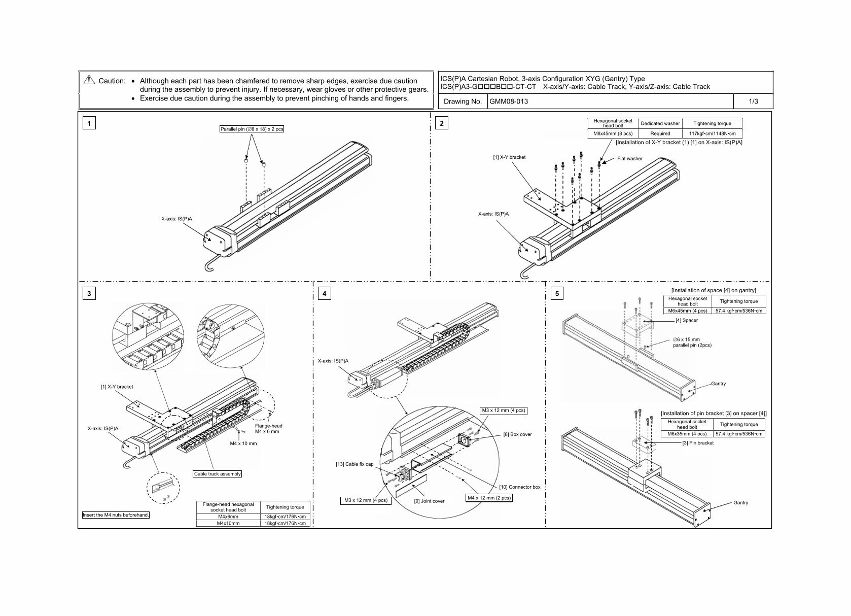
ICS(P)A Cartesian Robot, 3-axis Configuration XYG (Gantry) Type ICS(P)A3-G B -CT-CT X-axis/Y-axis: Cable Track, Y-axis/Z-axis: Cable Track
Caution: Although each part has been chamfered to remove sharp edges, exercise due caution during the assembly to prevent injury. If necessary, wear gloves or other protective gears.
Exercise due caution during the assembly to prevent pinching of hands and fingers. Drawing No. GMM08-013 1/3
1 2
4 53
Hexagonal socket head bolt Dedicated washer Tightening torque
M8x45mm (8 pcs) Required 117kgf cm/1148N cm
Flange-head hexagonal socket head bolt Tightening torque
M4x6mm 18kgf cm/176N cm M4x10mm 18kgf cm/176N cm
Hexagonal socket head bolt Tightening torque
M6x45mm (4 pcs) 57.4 kgf cm/536N cm
Hexagonal socket head bolt Tightening torque
M6x35mm (4 pcs) 57.4 kgf cm/536N cm
Parallel pin ( 8 x 18) x 2 pcs
X-axis: IS(P)A X-axis: IS(P)A
[1] X-Y bracket
[Installation of X-Y bracket (1) [1] on X-axis: IS(P)A]
[1] X-Y bracket
X-axis: IS(P)A
Cable track assembly
Insert the M4 nuts beforehand.
Flange-headM4 x 6 mm
X-axis: IS(P)A
[8] Box cover
[10] Connector box
[9] Joint cover
[13] Cable fix cap
M3 x 12 mm (4 pcs)
M3 x 12 mm (4 pcs)
M4 x 12 mm (2 pcs)
[Installation of space [4] on gantry]
[Installation of pin bracket [3] on spacer [4]]
[3] Pin bracket
Gantry
Flat washer
M4 x 10 mm
[4] Spacer
Gantry
6 x 15 mm parallel pin (2pcs)
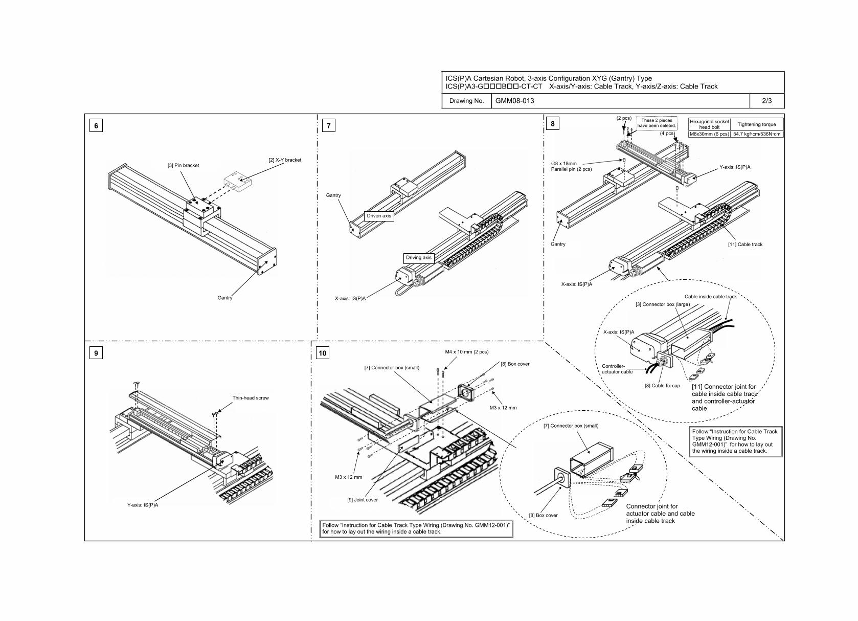
ICS(P)A Cartesian Robot, 3-axis Configuration XYG (Gantry) Type ICS(P)A3-G B -CT-CT X-axis/Y-axis: Cable Track, Y-axis/Z-axis: Cable Track
Drawing No. GMM08-013 2/3
6 7
9
8
10
8 x 18mm Parallel pin (2 pcs)
(4 pcs)
(2 pcs) Hexagonal socket
head bolt Tightening torque
M8x30mm (6 pcs) 54.7 kgf cm/536N cm
[2] X-Y bracket [3] Pin bracket
Gantry
Gantry
X-axis: IS(P)A
These 2 pieces have been deleted.
Gantry
Y-axis: IS(P)A
[11] Cable track
[3] Connector box (large)Cable inside cable track
Controller-actuator cable
X-axis: IS(P)A
[8] Cable fix cap [11] Connector joint for cable inside cable track and controller-actuator cable
X-axis: IS(P)A
Thin-head screw
Y-axis: IS(P)A [9] Joint cover
[7] Connector box (small) [8] Box cover
[7] Connector box (small)
[8] Box cover
Connector joint for actuator cable and cable inside cable track
M4 x 10 mm (2 pcs)
M3 x 12 mm
M3 x 12 mm
Driven axis
Driving axis
Follow “Instruction for Cable Track Type Wiring (Drawing No. GMM12-001)” for how to lay out the wiring inside a cable track.
Follow “Instruction for Cable Track Type Wiring (Drawing No. GMM12-001)” for how to lay out the wiring inside a cable track.
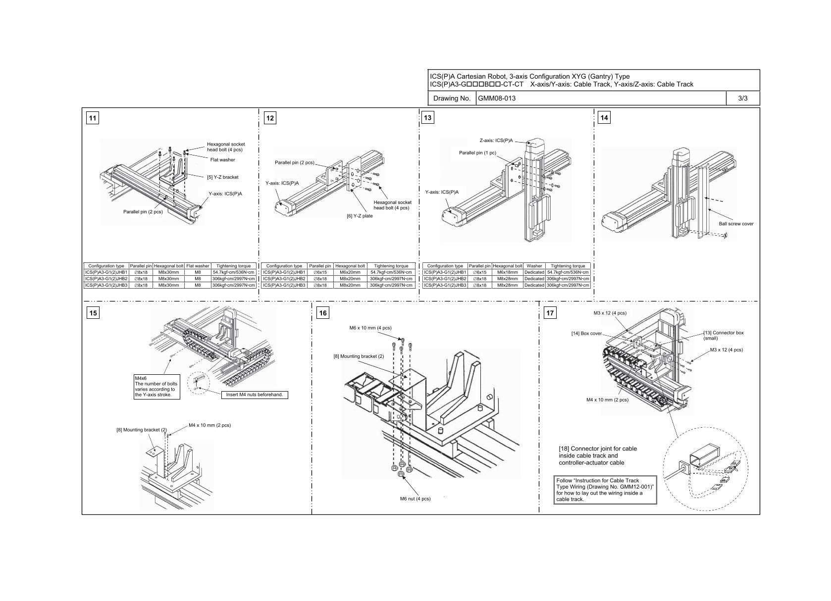
ICS(P)A Cartesian Robot, 3-axis Configuration XYG (Gantry) Type ICS(P)A3-G B -CT-CT X-axis/Y-axis: Cable Track, Y-axis/Z-axis: Cable Track
Drawing No. GMM08-013 3/3
11 12
16 1715
13 14
Configuration type Parallel pin Hexagonal bolt Flat washer Tightening torque ICS(P)A3-G1(2)JHB1 8x18 M8x30mm M8 54.7kgf cm/536N cmICS(P)A3-G1(2)JHB2 8x18 M8x30mm M8 306kgf cm/2997N cm ICS(P)A3-G1(2)JHB3 8x18 M8x30mm M8 306kgf cm/2997N cm
Configuration type Parallel pin Hexagonal bolt Tightening torque ICS(P)A3-G1(2)JHB1 6x15 M6x20mm 54.7kgf cm/536N cmICS(P)A3-G1(2)JHB2 8x18 M8x20mm 306kgf cm/2997N cmICS(P)A3-G1(2)JHB3 8x18 M8x20mm 306kgf cm/2997N cm
Configuration type Parallel pin Hexagonal bolt Washer Tightening torque ICS(P)A3-G1(2)JHB1 6x15 M6x18mm Dedicated 54.7kgf cm/536N cmICS(P)A3-G1(2)JHB2 8x18 M8x28mm Dedicated 306kgf cm/2997N cm ICS(P)A3-G1(2)JHB3 8x18 M8x28mm Dedicated 306kgf cm/2997N cm
Parallel pin (2 pcs)
Y-axis: ICS(P)A
[5] Y-Z bracket
Flat washer
Hexagonal socket head bolt (4 pcs)
Hexagonal socket head bolt (4 pcs)
Parallel pin (2 pcs)
Y-axis: ICS(P)A
Y-axis: ICS(P)A
Parallel pin (1 pc)
Z-axis: ICS(P)A
[6] Y-Z plate Ball screw cover
M4x6 The number of bolts varies according to the Y-axis stroke. Insert M4 nuts beforehand.
[8] Mounting bracket (2) M4 x 10 mm (2 pcs)
M6 x 10 mm (4 pcs)
[8] Mounting bracket (2)
M3 x 12 (4 pcs)
M4 x 10 mm (2 pcs)
[13] Connector box (small)
[14] Box cover
[18] Connector joint for cable inside cable track and controller-actuator cable
M3 x 12 (4 pcs)
M6 nut (4 pcs)
Follow “Instruction for Cable Track Type Wiring (Drawing No. GMM12-001)” for how to lay out the wiring inside a cable track.
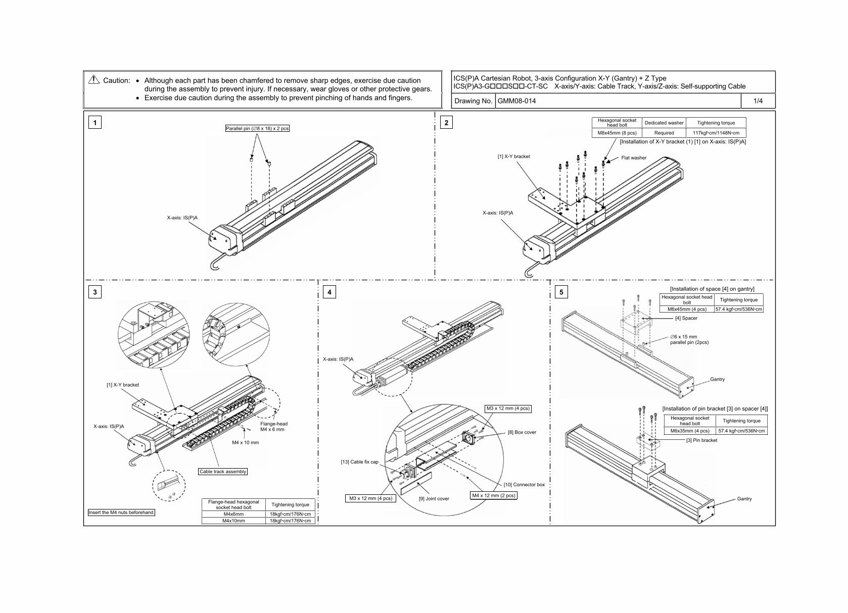
ICS(P)A Cartesian Robot, 3-axis Configuration X-Y (Gantry) + Z Type ICS(P)A3-G S -CT-SC X-axis/Y-axis: Cable Track, Y-axis/Z-axis: Self-supporting Cable
Caution: Although each part has been chamfered to remove sharp edges, exercise due caution during the assembly to prevent injury. If necessary, wear gloves or other protective gears.
Exercise due caution during the assembly to prevent pinching of hands and fingers. Drawing No. GMM08-014 1/4
1 2
4 53
Hexagonal socket head bolt Dedicated washer Tightening torque
M8x45mm (8 pcs) Required 117kgf cm/1148N cm
Flange-head hexagonal socket head bolt Tightening torque
M4x6mm 18kgf cm/176N cm M4x10mm 18kgf cm/176N cm
Hexagonal socket head bolt Tightening torque
M6x45mm (4 pcs) 57.4 kgf cm/536N cm
Hexagonal socket head bolt Tightening torque
M6x35mm (4 pcs) 57.4 kgf cm/536N cm
Parallel pin ( 8 x 18) x 2 pcs
X-axis: IS(P)A X-axis: IS(P)A
[1] X-Y bracket
[Installation of X-Y bracket (1) [1] on X-axis: IS(P)A]
[1] X-Y bracket
X-axis: IS(P)A
Cable track assembly
Insert the M4 nuts beforehand.
Flange-headM4 x 6 mm
X-axis: IS(P)A
[8] Box cover
[10] Connector box
[9] Joint cover
[13] Cable fix cap
M3 x 12 mm (4 pcs)
M3 x 12 mm (4 pcs)
M4 x 12 mm (2 pcs)
[Installation of space [4] on gantry]
[Installation of pin bracket [3] on spacer [4]]
[4] Spacer
Gantry
[3] Pin bracket
Gantry
6 x 15 mm parallel pin (2pcs)
Flat washer
M4 x 10 mm
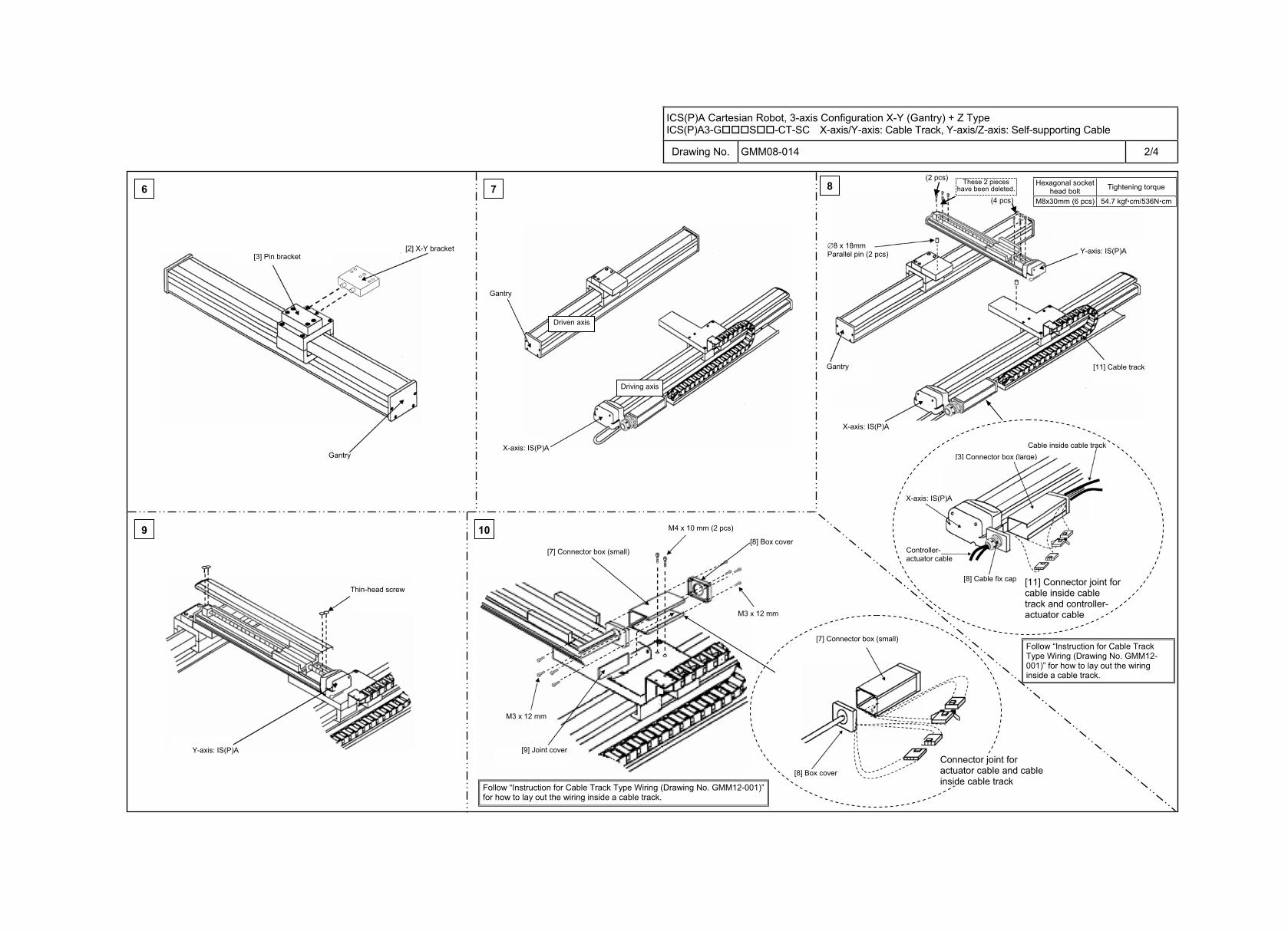
ICS(P)A Cartesian Robot, 3-axis Configuration X-Y (Gantry) + Z Type ICS(P)A3-G S -CT-SC X-axis/Y-axis: Cable Track, Y-axis/Z-axis: Self-supporting Cable
Drawing No. GMM08-014 2/4
6 7
9
8
10
8 x 18mm Parallel pin (2 pcs)
(4 pcs)
(2 pcs) Hexagonal socket
head bolt Tightening torque
M8x30mm (6 pcs) 54.7 kgf cm/536N cm
[2] X-Y bracket [3] Pin bracket
Gantry
Gantry
X-axis: IS(P)A
These 2 pieces have been deleted.
Gantry
Y-axis: IS(P)A
[11] Cable track
[3] Connector box (large)Cable inside cable track
X-axis: IS(P)A
[8] Cable fix cap [11] Connector joint for cable inside cable track and controller-actuator cable
X-axis: IS(P)A
Thin-head screw
Y-axis: IS(P)A [9] Joint cover
[7] Connector box (small) [8] Box cover
[7] Connector box (small)
[8] Box cover
Connector joint for actuator cable and cable inside cable track
M4 x 10 mm (2 pcs)
M3 x 12 mm
M3 x 12 mm
Driving axis
Controller-actuator cable
Driven axis
Follow “Instruction for Cable Track Type Wiring (Drawing No. GMM12-001)” for how to lay out the wiring inside a cable track.
Follow “Instruction for Cable Track Type Wiring (Drawing No. GMM12-001)” for how to lay out the wiring inside a cable track.
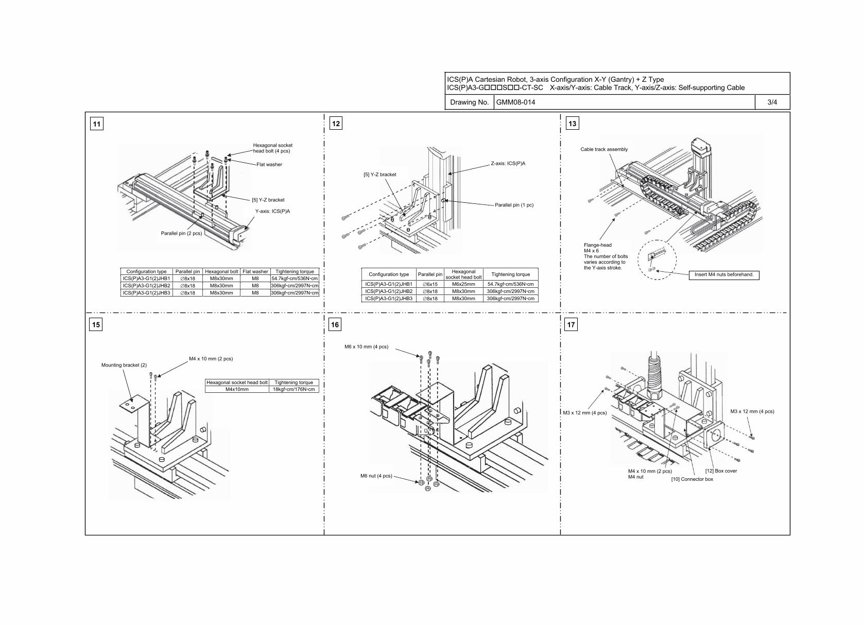
ICS(P)A Cartesian Robot, 3-axis Configuration X-Y (Gantry) + Z Type ICS(P)A3-G S -CT-SC X-axis/Y-axis: Cable Track, Y-axis/Z-axis: Self-supporting Cable
Drawing No. GMM08-014 3/4
11 12
16 1715
13
Configuration type Parallel pin Hexagonal bolt Flat washer Tightening torque ICS(P)A3-G1(2)JHB1 8x18 M8x30mm M8 54.7kgf cm/536N cmICS(P)A3-G1(2)JHB2 8x18 M8x30mm M8 306kgf cm/2997N cm ICS(P)A3-G1(2)JHB3 8x18 M8x30mm M8 306kgf cm/2997N cm
Configuration type Parallel pin Hexagonal socket head bolt Tightening torque
ICS(P)A3-G1(2)JHB1 6x15 M6x25mm 54.7kgf cm/536N cmICS(P)A3-G1(2)JHB2 8x18 M8x30mm 306kgf cm/2997N cmICS(P)A3-G1(2)JHB3 8x18 M8x30mm 306kgf cm/2997N cm
Parallel pin (2 pcs)
Y-axis: ICS(P)A
[5] Y-Z bracket
Flat washer
Hexagonal socket head bolt (4 pcs)
Z-axis: ICS(P)A
Parallel pin (1 pc)
[5] Y-Z bracket
Flange-headM4 x 6 The number of bolts varies according to the Y-axis stroke.
Insert M4 nuts beforehand.
Cable track assembly
Mounting bracket (2) M4 x 10 mm (2 pcs)
M3 x 12 mm (4 pcs)
[10] Connector box
[12] Box cover
M3 x 12 mm (4 pcs)
M4 x 10 mm (2 pcs) M4 nut
M6 x 10 mm (4 pcs)
M6 nut (4 pcs)
Hexagonal socket head bolt Tightening torque M4x10mm 18kgf cm/176N cm
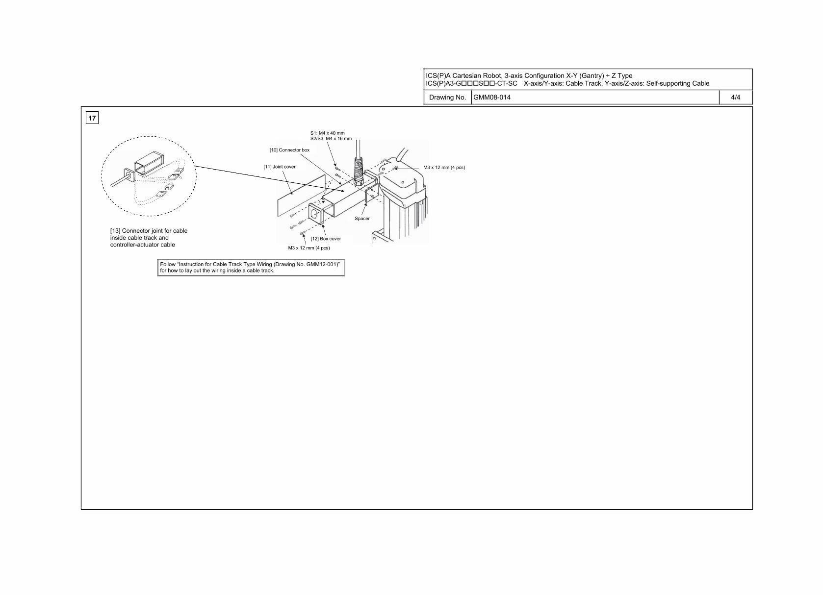
ICS(P)A Cartesian Robot, 3-axis Configuration X-Y (Gantry) + Z Type ICS(P)A3-G S -CT-SC X-axis/Y-axis: Cable Track, Y-axis/Z-axis: Self-supporting Cable
Drawing No. GMM08-014 4/4
17
[10] Connector box
[12] Box cover [13] Connector joint for cable inside cable track and controller-actuator cable
[11] Joint cover
M3 x 12 mm (4 pcs)
M3 x 12 mm (4 pcs)
Spacer
S1: M4 x 40 mm S2/S3: M4 x 16 mm
Follow “Instruction for Cable Track Type Wiring (Drawing No. GMM12-001)” for how to lay out the wiring inside a cable track.
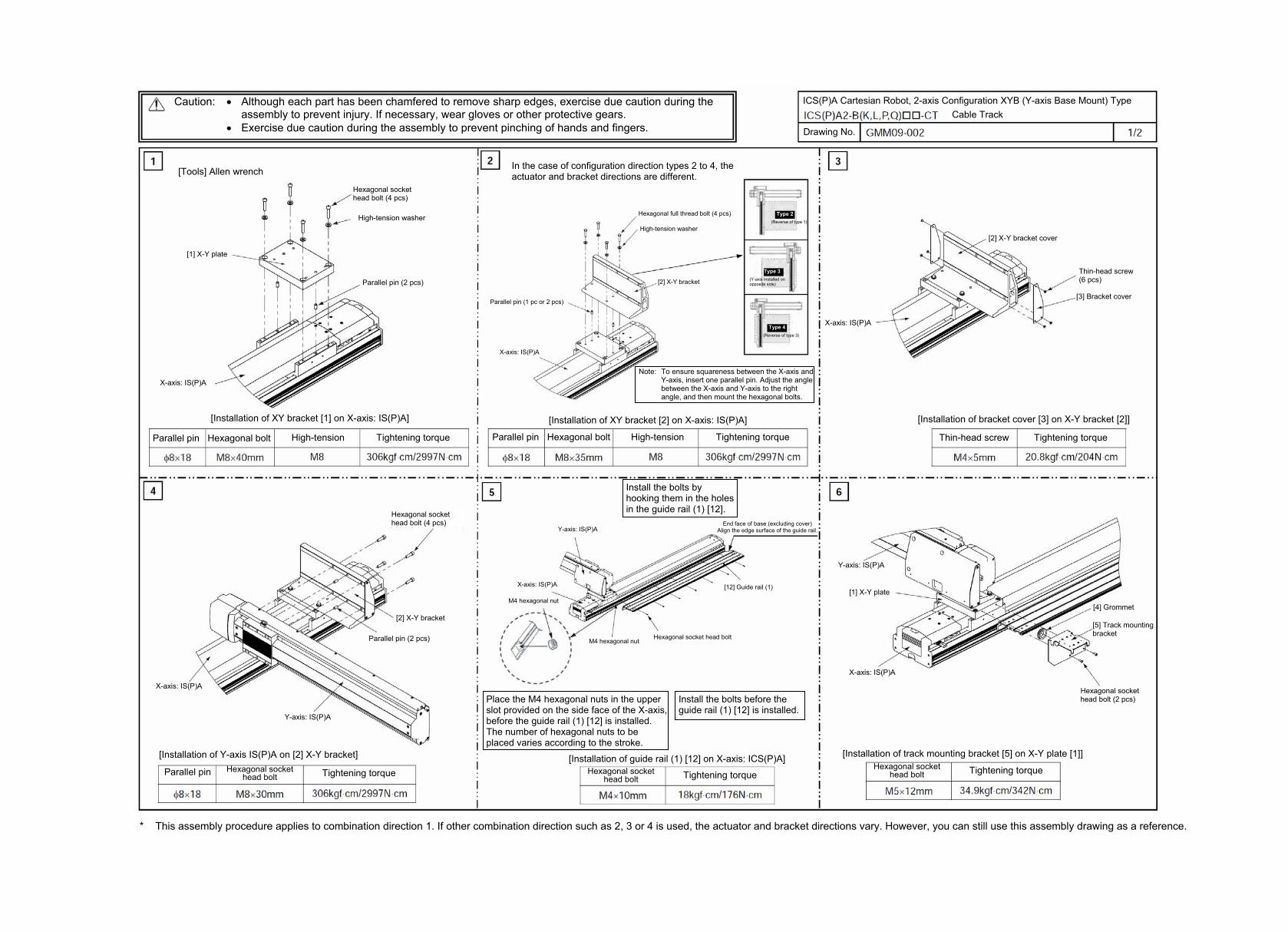
* This assembly procedure applies to combination direction 1. If other combination direction such as 2, 3 or 4 is used, the actuator and bracket directions vary. However, you can still use this assembly drawing as a reference.
Drawing No.
Caution: Although each part has been chamfered to remove sharp edges, exercise due caution during the assembly to prevent injury. If necessary, wear gloves or other protective gears.
Exercise due caution during the assembly to prevent pinching of hands and fingers.
ICS(P)A Cartesian Robot, 2-axis Configuration XYB (Y-axis Base Mount) Type Cable Track
[Tools] Allen wrench
Parallel pin (2 pcs)
Hexagonal socket head bolt (4 pcs)
X-axis: IS(P)A
High-tension washer
[1] X-Y plate
[Installation of XY bracket [1] on X-axis: IS(P)A]
Parallel pin Hexagonal bolt Tightening torque High-tension
In the case of configuration direction types 2 to 4, the actuator and bracket directions are different.
Hexagonal full thread bolt (4 pcs)
High-tension washer
[2] X-Y bracket
Parallel pin (1 pc or 2 pcs)
X-axis: IS(P)A
Type 2(Reverse of type 1)
Type 3(Y-axis installed on opposite side)
Type 4(Reverse of type 3)
Note: To ensure squareness between the X-axis and Y-axis, insert one parallel pin. Adjust the angle between the X-axis and Y-axis to the right angle, and then mount the hexagonal bolts.
[Installation of XY bracket [2] on X-axis: IS(P)A]
Parallel pin Hexagonal bolt Tightening torque High-tension
X-axis: IS(P)A
[2] X-Y bracket cover
Thin-head screw (6 pcs)
[3] Bracket cover
[Installation of bracket cover [3] on X-Y bracket [2]]
Tightening torque Thin-head screw
Hexagonal socket head bolt (4 pcs)
X-axis: IS(P)A
Y-axis: IS(P)A
Parallel pin (2 pcs)
[2] X-Y bracket
[Installation of Y-axis IS(P)A on [2] X-Y bracket]
Parallel pin Hexagonal socket head bolt Tightening torque
Y-axis: IS(P)A
X-axis: IS(P)A
M4 hexagonal nut
M4 hexagonal nut Hexagonal socket head bolt
[12] Guide rail (1)
Install the bolts by hooking them in the holes in the guide rail (1) [12].
End face of base (excluding cover) Align the edge surface of the guide rail.
Place the M4 hexagonal nuts in the upper slot provided on the side face of the X-axis, before the guide rail (1) [12] is installed. The number of hexagonal nuts to be placed varies according to the stroke.
Install the bolts before the guide rail (1) [12] is installed.
[Installation of guide rail (1) [12] on X-axis: ICS(P)A]Hexagonal socket
head bolt Tightening torque Hexagonal socket
head bolt Tightening torque
Y-axis: IS(P)A
[1] X-Y plate
X-axis: IS(P)A
[4] Grommet
[5] Track mounting bracket
Hexagonal socket head bolt (2 pcs)
[Installation of track mounting bracket [5] on X-Y plate [1]]
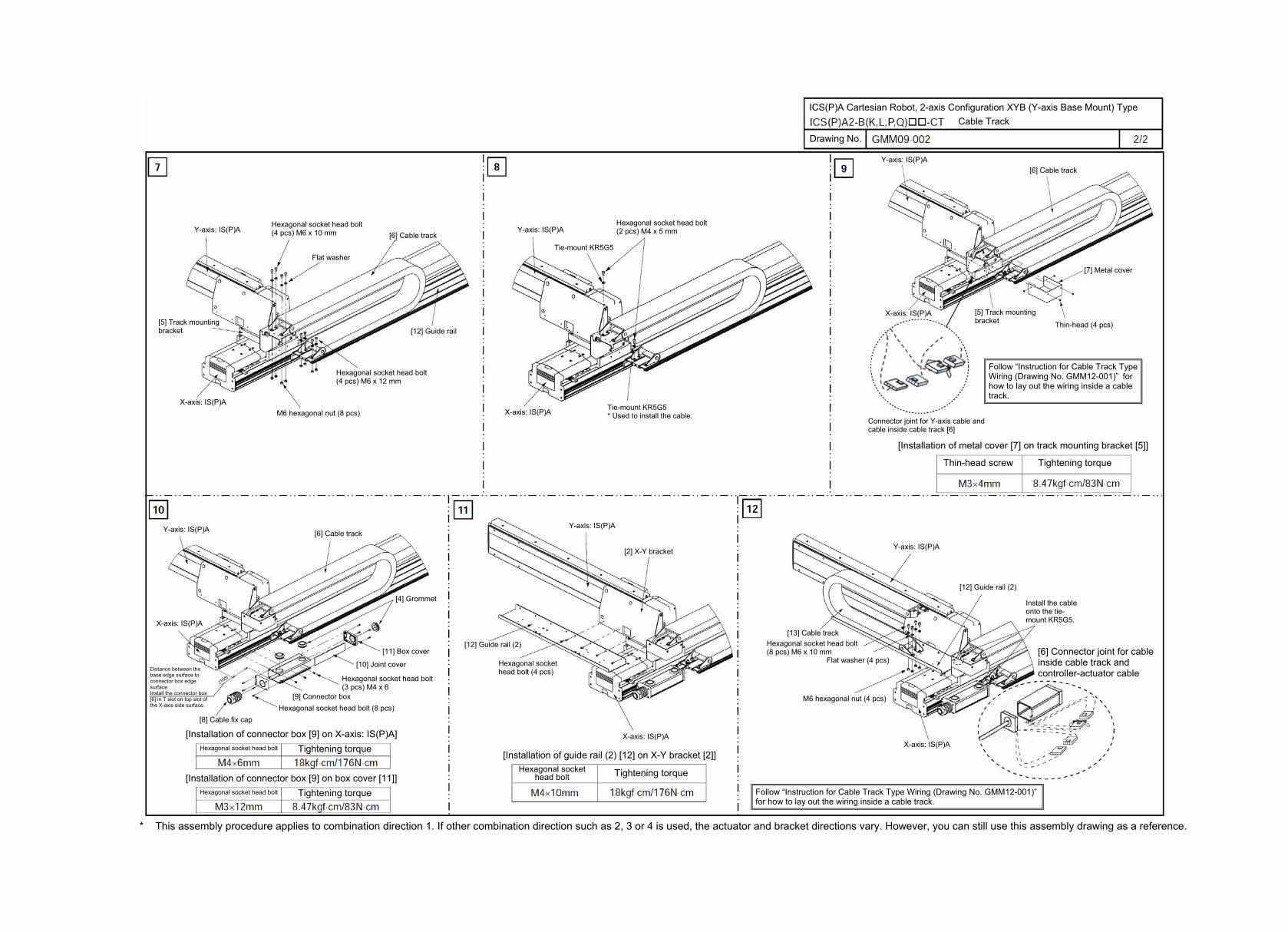
* This assembly procedure applies to combination direction 1. If other combination direction such as 2, 3 or 4 is used, the actuator and bracket directions vary. However, you can still use this assembly drawing as a reference.
Drawing No.
ICS(P)A Cartesian Robot, 2-axis Configuration XYB (Y-axis Base Mount) Type Cable Track
X-axis: IS(P)A
Y-axis: IS(P)A
[5] Track mounting bracket
Hexagonal socket head bolt (4 pcs) M6 x 10 mm [6] Cable track
Flat washer
M6 hexagonal nut (8 pcs)
Hexagonal socket head bolt (4 pcs) M6 x 12 mm
[12] Guide rail
Y-axis: IS(P)A
X-axis: IS(P)A Tie-mount KR5G5 * Used to install the cable.
Tie-mount KR5G5
Hexagonal socket head bolt (2 pcs) M4 x 5 mm
Y-axis: IS(P)A
X-axis: IS(P)A
[6] Cable track
[7] Metal cover
Thin-head (4 pcs)
[5] Track mounting bracket
Connector joint for Y-axis cable and cable inside cable track [6]
[Installation of metal cover [7] on track mounting bracket [5]]
Tightening torque Thin-head screw
Y-axis: IS(P)A [6] Cable track
X-axis: IS(P)A
[4] Grommet
[11] Box cover
[10] Joint cover
Hexagonal socket head bolt (3 pcs) M4 x 6
[9] Connector boxHexagonal socket head bolt (8 pcs)
[8] Cable fix cap
Distance between the base edge surface to connector box edge surface Install the connector box [6] in T slot on top slot of the X-axis side surface.
[Installation of connector box [9] on X-axis: IS(P)A] Hexagonal socket head bolt Tightening torque
[Installation of connector box [9] on box cover [11]] Hexagonal socket head bolt Tightening torque
Hexagonal socket head bolt Tightening torque
X-axis: IS(P)A
Hexagonal socket head bolt (4 pcs)
[12] Guide rail (2)
Y-axis: IS(P)A
[2] X-Y bracket
[Installation of guide rail (2) [12] on X-Y bracket [2]]
Y-axis: IS(P)A
[13] Cable trackHexagonal socket head bolt (8 pcs) M6 x 10 mm
Flat washer (4 pcs)
[12] Guide rail (2)
Install the cable onto the tie-mount KR5G5.
M6 hexagonal nut (4 pcs)
X-axis: IS(P)A
[6] Connector joint for cable inside cable track and controller-actuator cable
Follow “Instruction for Cable Track Type Wiring (Drawing No. GMM12-001)” for how to lay out the wiring inside a cable track.
Follow “Instruction for Cable Track Type Wiring (Drawing No. GMM12-001)” forhow to lay out the wiring inside a cable track.
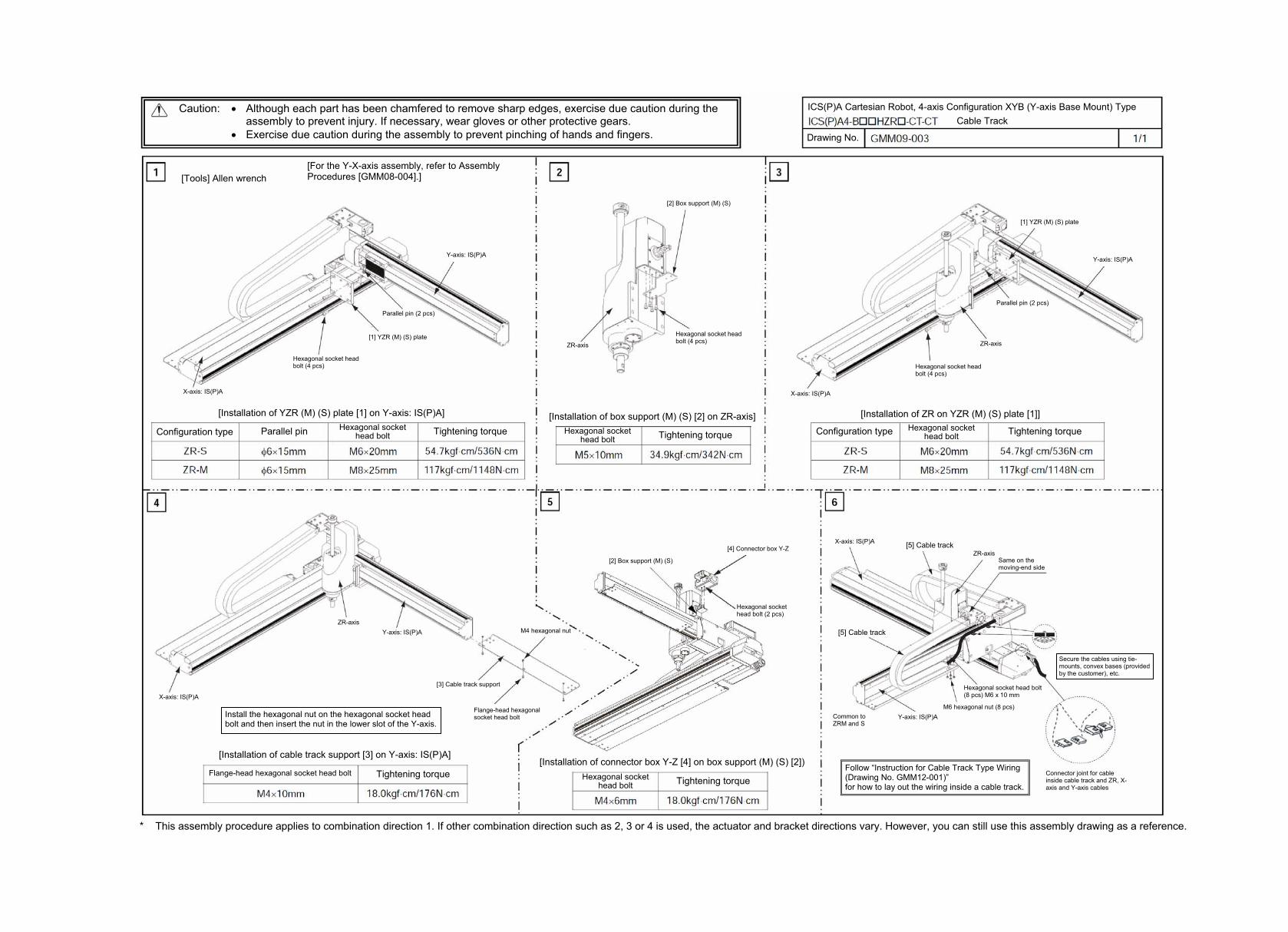
* This assembly procedure applies to combination direction 1. If other combination direction such as 2, 3 or 4 is used, the actuator and bracket directions vary. However, you can still use this assembly drawing as a reference.
Caution: Although each part has been chamfered to remove sharp edges, exercise due caution during the assembly to prevent injury. If necessary, wear gloves or other protective gears.
Exercise due caution during the assembly to prevent pinching of hands and fingers.
ICS(P)A Cartesian Robot, 4-axis Configuration XYB (Y-axis Base Mount) Type Cable Track
Drawing No.
[Tools] Allen wrench
Parallel pin (2 pcs)
Hexagonal socket head bolt (4 pcs)
Y-axis: IS(P)A
X-axis: IS(P)A
[For the Y-X-axis assembly, refer to Assembly Procedures [GMM08-004].]
[1] YZR (M) (S) plate
[Installation of YZR (M) (S) plate [1] on Y-axis: IS(P)A]
Parallel pin Tightening torque Hexagonal socket head bolt Configuration type
[2] Box support (M) (S)
Hexagonal socket head bolt (4 pcs) ZR-axis
[Installation of box support (M) (S) [2] on ZR-axis]
Tightening torque Hexagonal socket head bolt
Parallel pin (2 pcs)
Hexagonal socket head bolt (4 pcs)
Y-axis: IS(P)A
X-axis: IS(P)A
[1] YZR (M) (S) plate
ZR-axis
[Installation of ZR on YZR (M) (S) plate [1]]
Tightening torque Hexagonal socket head bolt Configuration type
Y-axis: IS(P)A
X-axis: IS(P)A
ZR-axis
Install the hexagonal nut on the hexagonal socket head bolt and then insert the nut in the lower slot of the Y-axis.
[Installation of cable track support [3] on Y-axis: IS(P)A]
Tightening torque Flange-head hexagonal socket head bolt
[3] Cable track support
Flange-head hexagonal socket head bolt
M4 hexagonal nut
[2] Box support (M) (S)
[4] Connector box Y-Z
Hexagonal socket head bolt (2 pcs)
[Installation of connector box Y-Z [4] on box support (M) (S) [2])
Tightening torque Hexagonal socket head bolt
X-axis: IS(P)A [5] Cable track ZR-axis
Same on the moving-end side
[5] Cable track
Common to ZRM and S
Y-axis: IS(P)A
Hexagonal socket head bolt (8 pcs) M6 x 10 mm
M6 hexagonal nut (8 pcs)
Secure the cables using tie-mounts, convex bases (provided by the customer), etc.
Connector joint for cable inside cable track and ZR, X-axis and Y-axis cables
Follow “Instruction for Cable Track Type Wiring (Drawing No. GMM12-001)” for how to lay out the wiring inside a cable track.
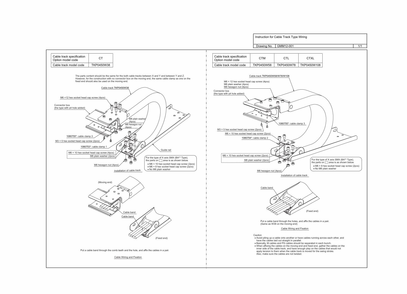
Instruction for Cable Track Type Wiring
Drawing No. GMM12-001 1/1
Cable track specification Option model code CTM CTL CTXL
Cable track model code TKP0450W58 TKP0450W78 TKP0450W108
Cable track specification Option model code CT
Cable track model code TKP0450W38
The parts content should be the same for the both cable tracks between X and Y and between Y and Z.However, for the construction with no connector box on the moving end, the same cable clamp as one on the fixed end should also be used on the moving end.
Cable track TKP0450W38
M6 ×12 hex socket head cap screw (4pcs)
M6 × 10 hex socket head cap screw (4pcs)M6 plain washer (2pcs)
M6 plain washer (4pcs)
M3 × 5 hex socket head cap screw (2pcs)
Connector box (the type with φ4 hole added)
1080755*: cable clamp 3
1080753*: cable clamp 1
M6 hexagon nut (4pcs)
M6 hexagon nut (4pcs)
Installation of cable track
Cable Wiring and Fixation
Cable band
Cable band
Put a cable band through the comb teeth and the hole, and affix the cables in a pair.
Guide rail
For the type of X axis SMX (BA** Type), the parts on area is as shown below. • M6 × 10 hex socket head cap screw (2pcs) • M6 × 8 hex socket head cap screw (2pcs) • No M6 plain washer
(Moving end)
(Fixed end)
Installation of cable track
Cable Wiring and Fixation
Put a cable band through the holes, and affix the cables in a pair.(Same as W38 on the moving end)
Cable band
Cable track TKP0450W58/W78/W108
M6 × 12 hex socket head cap screw (4pcs)M6 plain washer (4pcs)M6 hexagon nut (4pcs)
M6 × 10 hex socket head cap screw (2pcs)
M3 × 5 hex socket head cap screw (2pcs)
Connector box (the type with φ4 hole added)
1080755*: cable clamp 3
1080754*: cable clamp 2
M6 hexagon nut (4pcs)
For the type of X axis SMX (BA** Type), the parts on area is as shown below. • M6 × 8 hex socket head cap screw (2pcs) • No M6 plain washer
M6 × 10 hex socket head cap screw (2pcs)
M6 plain washer (2pcs)
(Fixed end)
Caution • Avoid piling up a cable onto another or have cables running across each other, and
have the cables laid out straight in parallel. • Basically, M cables and PG cables should be separated in each bunch. • When affixing the cables on the moving end and fixed end, gather the cables on the
inner side of the cable track, and have enough play on the cables that would not apply tension to them when the cable track is moved for the swing stroke.Also, make sure the cables are not twisted.