Embed Size (px)
Citation preview
IDENTIFYING PRODUCT SCALING PRINCIPLES
A Thesis
by
ANGEL GERARDO PEREZ
Submitted to the Office of Graduate Studies of
Texas A&M University
in partial fulfillment of the requirements for the degree of
MASTER OF SCIENCE
August 2011
Major Subject: Mechanical Engineering
IDENTIFYING PRODUCT SCALING PRINCIPLES
A Thesis
by
ANGEL GERARDO PEREZ
Submitted to the Office of Graduate Studies of
Texas A&M University
in partial fulfillment of the requirements for the degree of
MASTER OF SCIENCE
Approved by:
Chair of Committee, Julie Linsey
Committee Members, Richard Malak
Michael Johnson
Head of Department, Dennis L. O‟Neal
August 2011
Major Subject: Mechanical Engineering
iii
ABSTRACT
Identifying Product Scaling Principles. (August 2011)
Angel Gerardo Perez, B.S., The University of Texas Pan American
Chair of Advisory Committee: Dr. Julie Linsey
There are countless products that perform the same function but are engineered
to suit a different scale. Designers are often faced with the problem of taking a solution
at one scale and mapping it to another. This frequently happens with design-by-analogy
and bioinspired design. Despite various scaling laws for specific systems, there are no
global principles for scaling systems, for example from a biological nano scale to macro
scale. This is likely one of the reasons that bioinspired design is difficult. Very often
scaling laws assume the same physical principles are being used, but this study of
products indicates that a variety of changes occur as scale changes including changing
the physical principles to meet a particular function. Empirical product research was
used to determine a set of principles by observing and understanding numerous products
and natural analogies to unearth new generalizations. The function a product performs is
examined at various scales to view subtle and blatant differences. Principles are then
determined. A case study validating the principles is also presented. Future work will
validate and measure the effectiveness of the principles for design.

iv
ACKNOWLEDGEMENTS
I would first like to thank my advisor, Dr. Linsey, for her guidance,
encouragement and support. Throughout my thesis period, she directed me in the right
direction, answered all the questions I asked and provided a lot of great ideas. Thanks to
the members of my committee, Dr. Malak and Dr. Johnson for their added support.
I would like to thank all my lab mates for their support as well as entertainment. I would
also like to thank Texas A&M University and the Department of Mechanical
Engineering for allowing me the opportunity to further my knowledge with such a
traditional and exceptional institution. Thanks to all my colleagues and the department
faculty and staff for making my time a memorable and joyful experience.
Thanks to all my friends for providing some needed fun. I wish to thank my entire
family and adopted families for all their support and encouragement throughout my time
at Texas A&M University. I especially want to thank my loving girlfriend for always
being there for me and forcing me to study and work. Finally, and most importantly, I
wish to thank my parents. Thank you for the daily phone calls and all the support and
love. I dedicate this thesis to them.
v
TABLE OF CONTENTS
Page
ABSTRACT ...................................................................................................................... iii
ACKNOWLEDGEMENTS .............................................................................................. iv
TABLE OF CONTENTS ................................................................................................... v
LIST OF FIGURES.......................................................................................................... vii
LIST OF TABLES ............................................................................................................. x
1. INTRODUCTION .......................................................................................................... 1
2. PRIOR WORK ............................................................................................................... 6
2.1 Dimensional Analysis and Similitude .............................................................. 6
2.1.1 Scaling Laws ..................................................................................... 8
2.1.2 Scaled Models ................................................................................... 9
2.2 Biomimetics ................................................................................................... 10
2.3 Product Platform and Product Families ......................................................... 12
2.4 Nanotechnology ............................................................................................. 14
3. EMPIRICAL PRODUCT STUDY .............................................................................. 16
3.1 Method ........................................................................................................... 16
3.1.1 Product Identification and Search Method ...................................... 18
3.1.2 Investigating Products ..................................................................... 21
3.2 Results and Discussion ................................................................................... 23
3.2.1 Example Products ............................................................................ 24
3.2.2 Determining Product Scale Differences .......................................... 27
3.2.3 Scaling Principles ............................................................................ 30
3.2.4 Integrating the Scaling Principles into a Reverse Engineering
and Redesign Method ...................................................................... 40
3.2.5 Energy Sources ................................................................................ 44
4. COMPARATIVE CASE STUDY ............................................................................... 51
vi
Page
4.1 Senior Design and Redesign Process Comparison ......................................... 52
4.2 Small Scale ..................................................................................................... 55
4.2.1 The Scaling Method with Small Scale Products ............................. 56
4.2.2 Small Scale Principle Results .......................................................... 65
4.3 Large Scale ..................................................................................................... 79
4.3.1 The Scaling Method with Large Scale Products ............................. 79
4.3.2 Large Scale Principle Results .......................................................... 83
4.4 Final Concept ................................................................................................. 93
4.5 Senior Design Concept and Scaling Concept Comparison ............................ 99
5. CONCLUSIONS AND FUTURE WORK ................................................................ 105
REFERENCES ............................................................................................................... 112
APPENDIX A ................................................................................................................ 122
APPENDIX B ................................................................................................................ 133
APPENDIX C ................................................................................................................ 136
APPENDIX D ................................................................................................................ 137
APPENDIX E ................................................................................................................. 139
APPENDIX F ................................................................................................................. 141
APPENDIX G ................................................................................................................ 144
APPENDIX H ................................................................................................................ 145
APPENDIX I .................................................................................................................. 146
VITA .............................................................................................................................. 151
vii
LIST OF FIGURES
Page
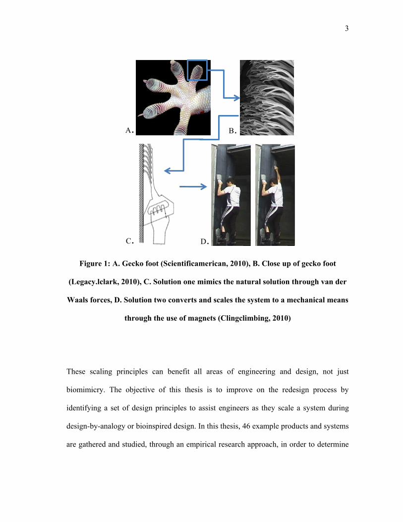
Figure 1: A. Gecko foot (Scientificamerican, 2010), B. Close up of gecko foot
(Legacy.lclark, 2010), C. Solution one mimics the natural solution through
van der Waals forces, D. Solution two converts and scales the system to a
mechanical means through the use of magnets (Clingclimbing, 2010) .............. 3
Figure 2: A. Goose grass plant (Openlearn A, 2011), B. Velcro close up (Openlearn
B, 2011) ............................................................................................................. 11
Figure 3: General and detailed empirical research approach Singh et al. (2009) ............ 17
Figure 4: Product search method ...................................................................................... 19
Figure 5: Examples of pecan shelling machines A. Manual nut cracker (Faqs, 2010),
B. Electric nut cracker (Lemfgco, 2010), C. Production shelling machine
(Biodiesel-machine, 2010) ................................................................................ 25
Figure 6: A. Hand air pump (Reviewsalert, 2011), B. Air compressor
(Aircompressorhut, 2011) ................................................................................. 28
Figure 7: A. Tape measure (Amazon, 2010), B. Laser tape
(Williamcameronwoodworking, 2010) ............................................................. 29
Figure 8: Examples “change energy source” A. Mechanical nutcracker powered by
the user (Faqs, 2010), B. Conversion to an electric production shelling
machine (Biodiesel-machine, 2010) .................................................................. 32
Figure 9: Examples “simplify system” A. Multi-step city water treatment plant
(Durhamcountync, 2010), B. Simplified to a one step portable filter bag by
removing additional, unnecessary steps (Rei, 2010) ........................................ 33
Figure 10: Examples “change method” A. Bandsaw blade (Bandsawcutting, 2010),
B. Replaced by a plasma cutter that converts gas into plasma to cut metal
(Samsoncnc, 2010) ............................................................................................ 35
Figure 11: Examples "combine functions” A. Multiple tool bread making facility
(Adventuresincapitalism, 2010), B. Combined into a single home bread
maker (Homeinteriorshome, 2010) ................................................................... 37
Figure 12: Examples “directly transfer components” A. The teeth on a cross-cut hand
saw (Homeconstructionshop, 2010), B. Transferred to a circular saw blade
(123rf, 2010) ...................................................................................................... 38
viii
Page
Figure 13: Examples “change parameters” A. Wheel barrow‟s physical parameters
(Blogs.riverfronttimes, 2010), B. Increased for an earth mover‟s new
capacity needs (Budologyproductions, 2010) ................................................... 40
Figure 14: Otto and Wood's redesign product development process (Otto & Wood,
2001) plus additional tasks that must occur to implement the scaling
principles properly ............................................................................................. 42
Figure 15: Direct energy transfer from pedals to rear wheel through gears and chain
(Flickr, 2010) ..................................................................................................... 47
Figure 16: Energy stored in flexible bows until released by trigger (Crankyfarmer,
2010) .................................................................................................................. 48
Figure 17: Shaking powered flashlight which converts mechanical energy into electric
through direct or indirect energy transfer (Geekalerts, 2010) ........................... 49
Figure 18: Senior and scaling design process that is based upon the redesign process
(Otto & Wood, 2001) ........................................................................................ 53
Figure 19: Manual push cart Black Box model ................................................................ 61
Figure 20: Electric push cart Black Box model ............................................................... 61
Figure 21: A. Manual and B. Electric push cart activity diagrams with highlighted
boxes that represent possible activities that can be simplified or combined
through the application of the „simplify system‟ and „combine functions‟
principles ........................................................................................................... 64
Figure 22: By applying the energy source principle and human powered checklist, a
sitting tricycle design was generated that is powered by the user ..................... 65
Figure 23: The „simplify principle‟ in conjunction with customer reviews revealed
that a one step unfolding process is preferred, similar to this product
(Bagboy, 2011) .................................................................................................. 67
Figure 24: A. Original cart wheel design B. Converted to a track system used to
transport the golf bag and user realized due to the „change method‟
principle ............................................................................................................. 68
Figure 25: The „change method‟ principle also led to possible golf bag securing ideas
such as adjustable brackets that are only adjusted once .................................... 69
ix
Page
Figure 26: The „parameter change‟ principle revealed these possible cart
configurations based on A. Four and three wheel setup with B. Two wheels
in front or C. One wheel in front ....................................................................... 72
Figure 27: Solar panel idea incorporated onto the base of the cart frame through
„energy source‟ principle ................................................................................... 73
Figure 28: Combining battery placement into cart and battery plug in by utilizing
metallic connection prongs, remove user plug .................................................. 75
Figure 29: EZ GO TXT electric golf cart (Batterysource, 2011) ..................................... 80
Figure 30: Electric Golf Cart Black Box Model .............................................................. 81
Figure 31: Electric Golf Cart activity diagram with highlighted boxes that represent
possible activities that can be simplified or combined through the
application of the scaling principles .................................................................. 83
Figure 32: Possible configuration of an electric motor with batteries and solar panel
derived from the „energy source‟ principle and automatic energy source
checklist ............................................................................................................. 84
Figure 33: Original rear housing with axles and differential simplified to a solid rear
axle design with incorporated brake and pulley grasped through the
application of the „simplify system‟ principle (Ezgo, 2011) ............................. 86
Figure 34: Potential suspension and steering configurations derived by applying the
„change method‟ principle ................................................................................. 87
Figure 35: Golf cart brake and parking brake pedal (Ocmonstercarts, 2011) .................. 88
Figure 36: Final design rendering incorporating all ideas generated by applying the
scaling principles ............................................................................................... 95
Figure 37: Ability of cart to fold to a compact size due to folding control arms and
handle and removable seat ................................................................................ 97
Figure 38: Ideas generated and incorporated from large and small principle
application ......................................................................................................... 99
Figure 39: Senior design team concept .......................................................................... 100
Figure 40: Differences between the senior design team final concept using a typical
design process and the scaling process utilizing the scaling principles .......... 103
x
LIST OF TABLES
Page
Table 1: Product class, example product and system selection criteria Saunders et al.
(2009) ................................................................................................................ 20
Table 2: “Pecan Sheller” Product class examples with individual sub-functions, in
functional basis, and how they are performed in order to easily review and
compare each product class ............................................................................... 23
Table 3: Comparison products ......................................................................................... 25
Table 4: Energy source checklist (Mechanism and energy types based on Otto &
Wood, 2001) ...................................................................................................... 45
Table 5: Scaling Manual Push Carts (Golf Smith, 2011) ................................................. 57
Table 6: Scaling Electric Push Carts (Sand Trap, The, 2011) .......................................... 60
Table 7: Manual push cart sub-functions ......................................................................... 62
Table 8: Electric push cart sub-functions ......................................................................... 63
Table 9: Push cart idea summary generated from scaling principles ............................... 76
Table 10: Electric golf cart sub-functions ........................................................................ 82
Table 11: Golf cart idea summary generated from scaling principles ............................. 89
1
1. INTRODUCTION
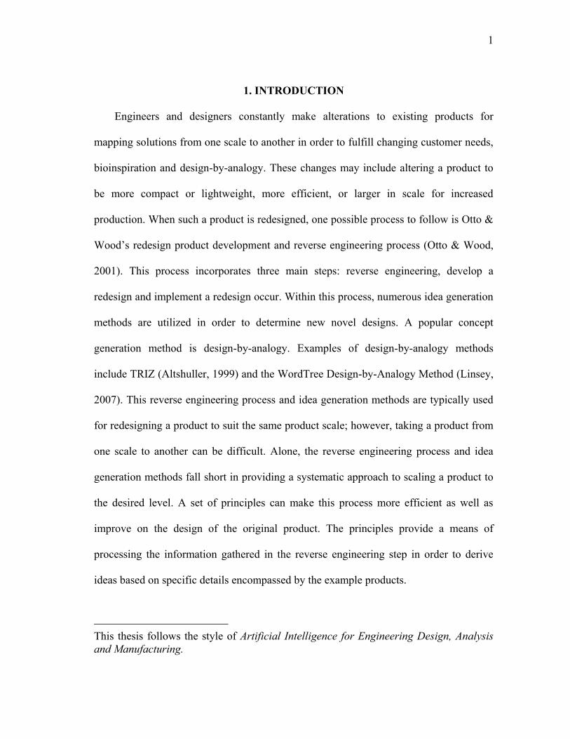
1Engineers and designers constantly make alterations to existing products for
mapping solutions from one scale to another in order to fulfill changing customer needs,
bioinspiration and design-by-analogy. These changes may include altering a product to
be more compact or lightweight, more efficient, or larger in scale for increased
production. When such a product is redesigned, one possible process to follow is Otto &
Wood‟s redesign product development and reverse engineering process (Otto & Wood,
2001). This process incorporates three main steps: reverse engineering, develop a
redesign and implement a redesign occur. Within this process, numerous idea generation
methods are utilized in order to determine new novel designs. A popular concept
generation method is design-by-analogy. Examples of design-by-analogy methods
include TRIZ (Altshuller, 1999) and the WordTree Design-by-Analogy Method (Linsey,
2007). This reverse engineering process and idea generation methods are typically used
for redesigning a product to suit the same product scale; however, taking a product from
one scale to another can be difficult. Alone, the reverse engineering process and idea
generation methods fall short in providing a systematic approach to scaling a product to
the desired level. A set of principles can make this process more efficient as well as
improve on the design of the original product. The principles provide a means of
processing the information gathered in the reverse engineering step in order to derive
ideas based on specific details encompassed by the example products.
This thesis follows the style of Artificial Intelligence for Engineering Design, Analysis
and Manufacturing.
2
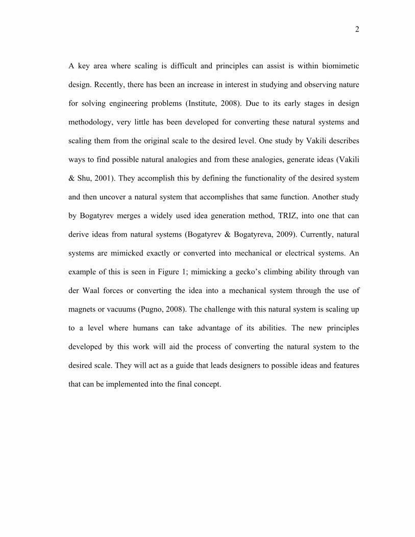
A key area where scaling is difficult and principles can assist is within biomimetic
design. Recently, there has been an increase in interest in studying and observing nature
for solving engineering problems (Institute, 2008). Due to its early stages in design
methodology, very little has been developed for converting these natural systems and
scaling them from the original scale to the desired level. One study by Vakili describes
ways to find possible natural analogies and from these analogies, generate ideas (Vakili
& Shu, 2001). They accomplish this by defining the functionality of the desired system
and then uncover a natural system that accomplishes that same function. Another study
by Bogatyrev merges a widely used idea generation method, TRIZ, into one that can
derive ideas from natural systems (Bogatyrev & Bogatyreva, 2009). Currently, natural
systems are mimicked exactly or converted into mechanical or electrical systems. An
example of this is seen in Figure 1; mimicking a gecko‟s climbing ability through van
der Waal forces or converting the idea into a mechanical system through the use of
magnets or vacuums (Pugno, 2008). The challenge with this natural system is scaling up
to a level where humans can take advantage of its abilities. The new principles
developed by this work will aid the process of converting the natural system to the
desired scale. They will act as a guide that leads designers to possible ideas and features
that can be implemented into the final concept.
3
Figure 1: A. Gecko foot (Scientificamerican, 2010), B. Close up of gecko foot
(Legacy.lclark, 2010), C. Solution one mimics the natural solution through van der
Waals forces, D. Solution two converts and scales the system to a mechanical means
through the use of magnets (Clingclimbing, 2010)
These scaling principles can benefit all areas of engineering and design, not just
biomimicry. The objective of this thesis is to improve on the redesign process by
identifying a set of design principles to assist engineers as they scale a system during
design-by-analogy or bioinspired design. In this thesis, 46 example products and systems
are gathered and studied, through an empirical research approach, in order to determine
A. B.
C. D.
4
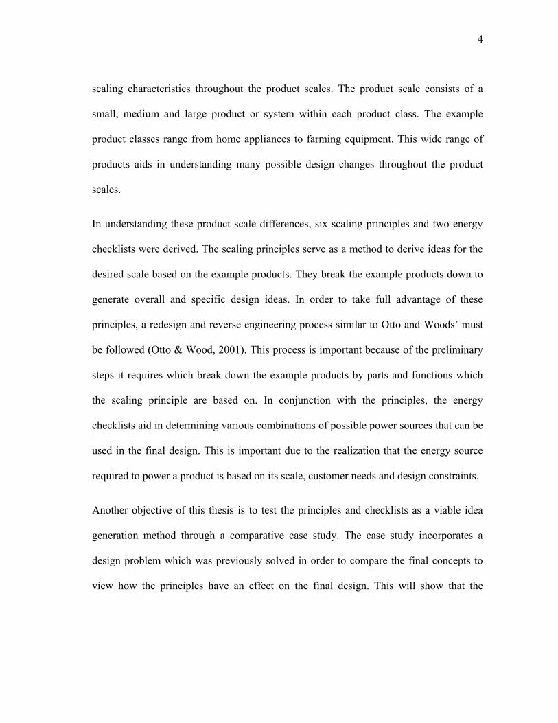
scaling characteristics throughout the product scales. The product scale consists of a
small, medium and large product or system within each product class. The example
product classes range from home appliances to farming equipment. This wide range of
products aids in understanding many possible design changes throughout the product
scales.
In understanding these product scale differences, six scaling principles and two energy
checklists were derived. The scaling principles serve as a method to derive ideas for the
desired scale based on the example products. They break the example products down to
generate overall and specific design ideas. In order to take full advantage of these
principles, a redesign and reverse engineering process similar to Otto and Woods‟ must
be followed (Otto & Wood, 2001). This process is important because of the preliminary
steps it requires which break down the example products by parts and functions which
the scaling principle are based on. In conjunction with the principles, the energy
checklists aid in determining various combinations of possible power sources that can be
used in the final design. This is important due to the realization that the energy source
required to power a product is based on its scale, customer needs and design constraints.
Another objective of this thesis is to test the principles and checklists as a viable idea
generation method through a comparative case study. The case study incorporates a
design problem which was previously solved in order to compare the final concepts to
view how the principles have an effect on the final design. This will show that the

5
principles add a new and improved insight into scaling that has not been previously
observed.
6
2. PRIOR WORK
Scaling is critical in many fields of engineering and design. There is plenty of work
previously performed on scaling theory, including dimensional analysis, similitude and
scaling laws. Scaling can also be applied to areas such as biomimetics, product design
including prototypes and product platforms, and even nanotechnology.
2.1 Dimensional Analysis and Similitude
Scaling is based on the theories of dimensional analysis and similarity. Dimensional
analysis is „a method by which we deduce information about a phenomenon from the
single premise that the phenomenon can be described by a dimensionally correct
equation among variables (Langhaar, 1951). This can be restated as a way to
comprehend physical data without dimensions. This method reduces the complexity of
problems to a simpler form by removing and simplifying certain variables the desired
quantity depends on. It allows for the dimensionless parameters to be acquired in order
for these variables to be removed. The Buckingham pi theorem is one way to determine
the amount of dimensionless numbers that will come out of the equation. This is the
number of dimensional variables minus the number of dimensions. Dimensionally
correct in the definition refers to the same dimensions on both sides of the equation, or
dimensionally homogeneous. Dimensional analysis is useful in a number of applications;
including a “check” of units in equations, conversion of units and determining
relationships when between product scales. It provides a tool for engineers to understand
and infer how a scaled system will behave when scaling occurs. The main advantage of
this theory is the fact that a solution can be acquired quickly because a detailed analysis
7
does not have to be performed. On the other hand, a complete solution is not obtained as
a detailed analysis would provide (Bridgeman, 1922).
There are several steps to properly use dimensional analysis in order to gain insight into
scaled systems. These steps minimize the possibility of missing a parameter in the
equation. Ipsen depicts a step-by-step approach that begins by first identifying all
variables the desired quantity depends on (Ipsen, 1960). The next step in the process is
determining the dimensions of these quantities in terms of length, mass, time etc. The
last step is removing dimensions from the variables one at a time in order to obtain a
dimensionless result.
Similitude or similarity is a relevant theory to dimensional analysis. Geometry was the
first area where similitude was used. It was noted that two shapes with different sizes
can be similar due to incorporating the same angles. Other types of similarity include
kinematic and dynamic similarity. Kinematic similarity refers to two objects or systems
that experience similar motions such as velocity or acceleration. Dynamic similarity is
when two objects or systems experience similar forces. Similitude is used in a number of
fields such as fluids, thermodynamics and dynamics. It can be used for testing scaled
models in product design. „The objective of a similarity method is to experimentally
predict the behavior of the target system through an indirect scaled testing, alleviating
complex system construction and testing effort‟(Otto & Wood, 2001).
8
2.1.1 Scaling Laws
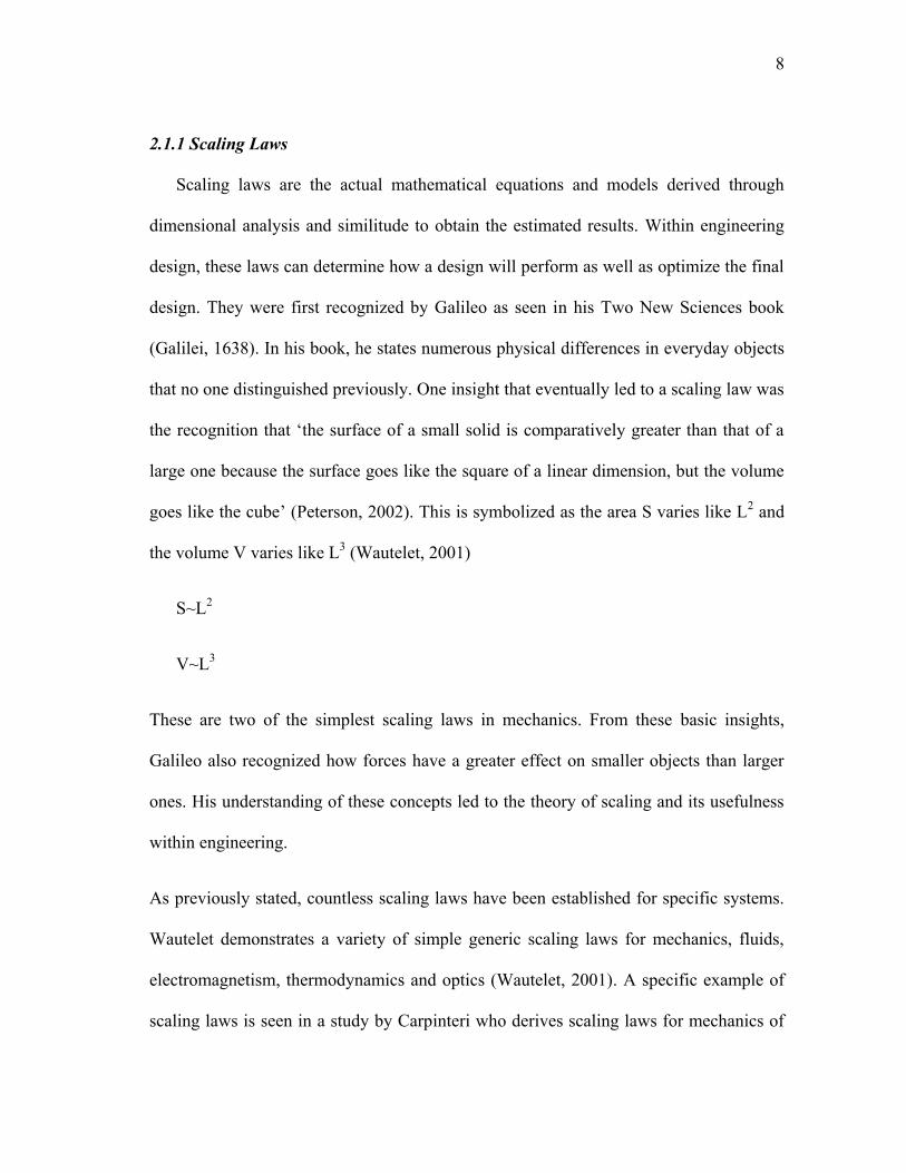
Scaling laws are the actual mathematical equations and models derived through
dimensional analysis and similitude to obtain the estimated results. Within engineering
design, these laws can determine how a design will perform as well as optimize the final
design. They were first recognized by Galileo as seen in his Two New Sciences book
(Galilei, 1638). In his book, he states numerous physical differences in everyday objects
that no one distinguished previously. One insight that eventually led to a scaling law was
the recognition that „the surface of a small solid is comparatively greater than that of a
large one because the surface goes like the square of a linear dimension, but the volume
goes like the cube‟ (Peterson, 2002). This is symbolized as the area S varies like L2 and
the volume V varies like L3 (Wautelet, 2001)
S~L2
V~L3
These are two of the simplest scaling laws in mechanics. From these basic insights,
Galileo also recognized how forces have a greater effect on smaller objects than larger
ones. His understanding of these concepts led to the theory of scaling and its usefulness
within engineering.
As previously stated, countless scaling laws have been established for specific systems.
Wautelet demonstrates a variety of simple generic scaling laws for mechanics, fluids,
electromagnetism, thermodynamics and optics (Wautelet, 2001). A specific example of
scaling laws is seen in a study by Carpinteri who derives scaling laws for mechanics of
9
materials, specifically on crack propagation Carpinteri et al. (2006). By utilizing the
dimensional analysis approach, scaling laws were derived in order to understand and
estimate how crack growth occurs in materials such as concrete. With these laws,
engineers can test how size and material property changes affect crack growth. Another
study shows how laws of similarity were determined for wind turbine rotors in order for
ease of optimization when scaling to the desired level (Peterson, 1984). The study
depicts how certain scaling laws for varying changes such as rotational speed, radius of
the rotor and even the incidence of the blades has an effect on the overall performance.
This allows for the optimal design to be obtained quickly. Scaling laws have also been
derived for optical lens systems as studied by Lohman (Lohman, 1989). They help
determine necessary changes in lens configuration and dimensions when scaled.
There are countless studies related to deriving and applying scaling laws for specific
systems. They provide insight into what specific details need to be altered when scaling,
such as the equations that relate to structural requirements needed to be considered for a
larger system. General scaling principles can be used in conjunction with dimensional
analysis for a more efficient means of designing a scaled product.
2.1.2 Scaled Models
Prototyping and testing of a product or system is an important step in the design
process, which relates to the previously described theories. They are used for a multitude
of intentions, including verifying analytical and numerical models, keeping development
costs low, as well as finding the performance and feasibility of a design (Otto & Wood,
10
2001). An example of this is testing a scaled airplane prototype in a wind tunnel to test
its aerodynamic performance before manufacturing the full scale model (Bushnell,
2005). By utilizing the proper scaling laws, this scaled down model provides useful
information on how the wing design will perform for the full-scale model. The scaling
laws help engineers determine how to build the model in order to take that data to the
desired full scale system. Material properties and structures can also be tested through
scaled down models; however in some cases it might not be suitable. When dynamic
loads are applied to structures as referenced by Oshiro and Alves, inaccurate values will
be determined due to improper scaling laws (Oshiro and Alves, 2009). When this occurs,
the model is said to be distorted or have imperfect similarity. These material choices for
the desired product scale must be accounted for individually through proper analysis.
Scaled model testing in conjunction with scaling laws help reduce design time as well as
provide information on what necessary changes are required when scaling.
2.2 Biomimetics
It is known that natural systems have evolved over millions of years to adapt and
thrive in numerous environments. These adaptations have been studied and tested in
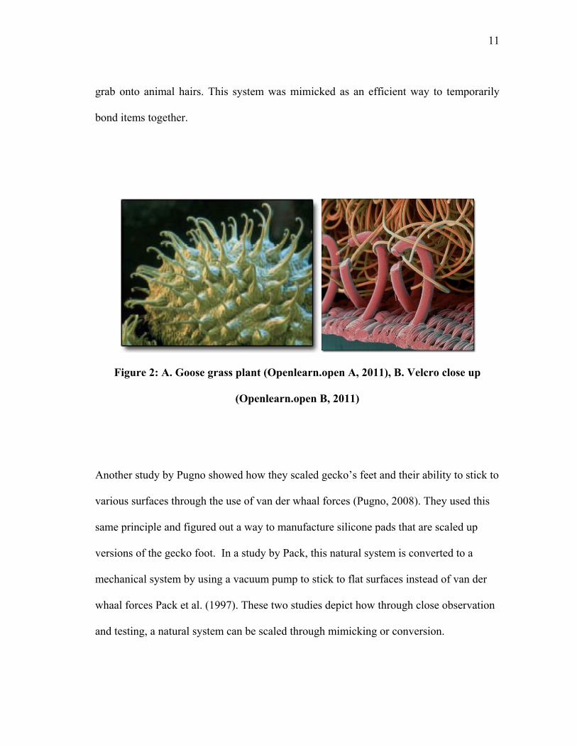
order to mimic or convert for our advantage. A product example of this is Velcro, as
seen in Figure 2. It was developed by George De Mestral who observed Galiumaparine
(goosegrass) and its fruits ability to cling to animals who came in contact with it Jackson
et al. (2009). The plant and fruit were studied in detail to first understand how this
occurred. Through close observation, the fruit revealed hook like prongs which would
11
grab onto animal hairs. This system was mimicked as an efficient way to temporarily
bond items together.
Figure 2: A. Goose grass plant (Openlearn.open A, 2011), B. Velcro close up
(Openlearn.open B, 2011)
Another study by Pugno showed how they scaled gecko‟s feet and their ability to stick to
various surfaces through the use of van der whaal forces (Pugno, 2008). They used this
same principle and figured out a way to manufacture silicone pads that are scaled up
versions of the gecko foot. In a study by Pack, this natural system is converted to a
mechanical system by using a vacuum pump to stick to flat surfaces instead of van der
whaal forces Pack et al. (1997). These two studies depict how through close observation
and testing, a natural system can be scaled through mimicking or conversion.
12
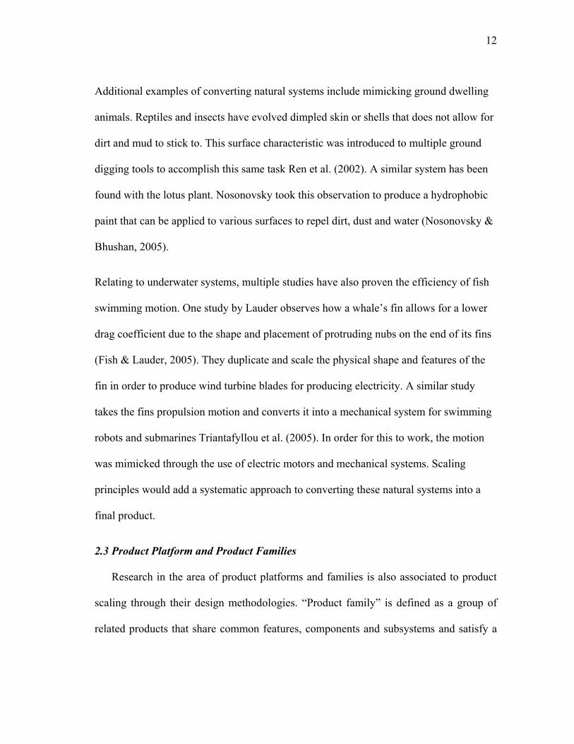
Additional examples of converting natural systems include mimicking ground dwelling
animals. Reptiles and insects have evolved dimpled skin or shells that does not allow for
dirt and mud to stick to. This surface characteristic was introduced to multiple ground
digging tools to accomplish this same task Ren et al. (2002). A similar system has been
found with the lotus plant. Nosonovsky took this observation to produce a hydrophobic
paint that can be applied to various surfaces to repel dirt, dust and water (Nosonovsky &
Bhushan, 2005).
Relating to underwater systems, multiple studies have also proven the efficiency of fish
swimming motion. One study by Lauder observes how a whale‟s fin allows for a lower
drag coefficient due to the shape and placement of protruding nubs on the end of its fins
(Fish & Lauder, 2005). They duplicate and scale the physical shape and features of the
fin in order to produce wind turbine blades for producing electricity. A similar study
takes the fins propulsion motion and converts it into a mechanical system for swimming
robots and submarines Triantafyllou et al. (2005). In order for this to work, the motion
was mimicked through the use of electric motors and mechanical systems. Scaling
principles would add a systematic approach to converting these natural systems into a
final product.
2.3 Product Platform and Product Families
Research in the area of product platforms and families is also associated to product
scaling through their design methodologies. “Product family” is defined as a group of
related products that share common features, components and subsystems and satisfy a
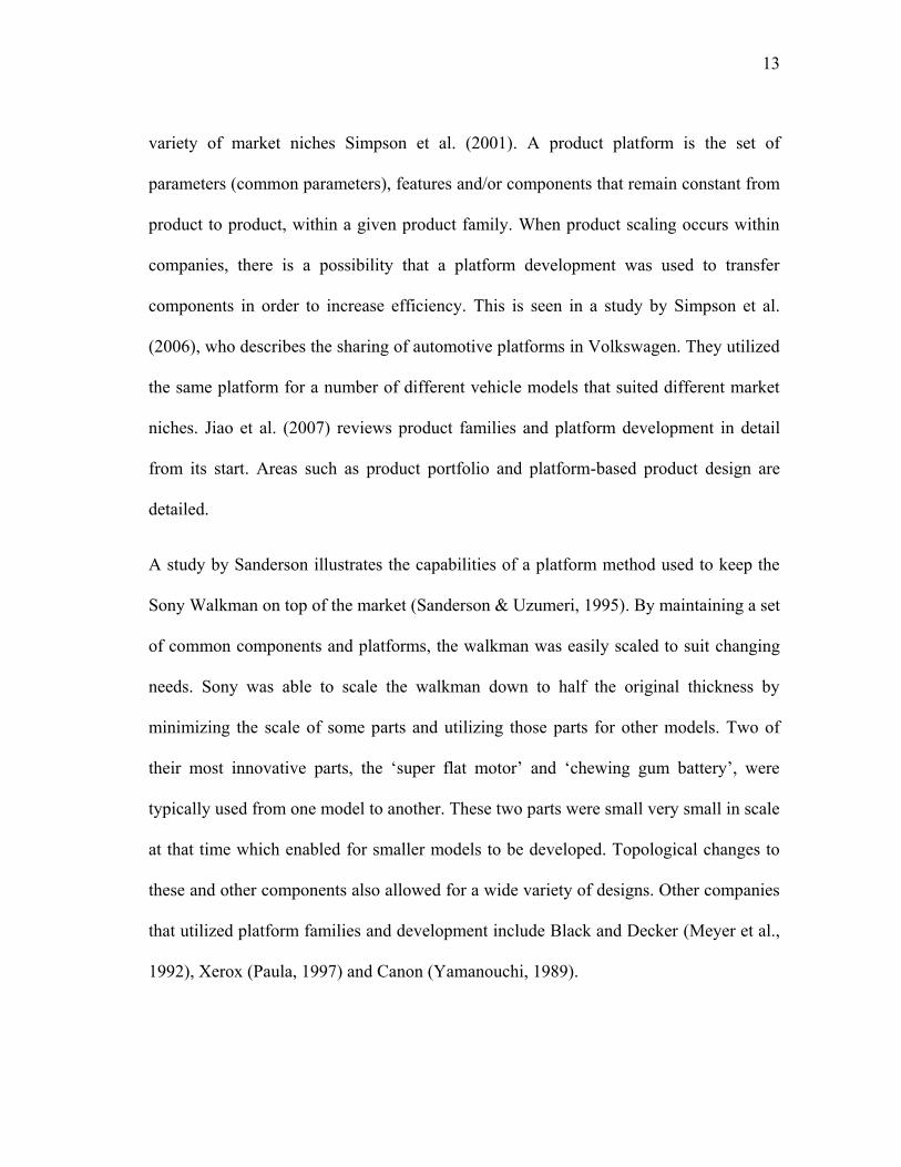
13
variety of market niches Simpson et al. (2001). A product platform is the set of
parameters (common parameters), features and/or components that remain constant from
product to product, within a given product family. When product scaling occurs within
companies, there is a possibility that a platform development was used to transfer
components in order to increase efficiency. This is seen in a study by Simpson et al.
(2006), who describes the sharing of automotive platforms in Volkswagen. They utilized
the same platform for a number of different vehicle models that suited different market
niches. Jiao et al. (2007) reviews product families and platform development in detail
from its start. Areas such as product portfolio and platform-based product design are
detailed.
A study by Sanderson illustrates the capabilities of a platform method used to keep the
Sony Walkman on top of the market (Sanderson & Uzumeri, 1995). By maintaining a set
of common components and platforms, the walkman was easily scaled to suit changing
needs. Sony was able to scale the walkman down to half the original thickness by
minimizing the scale of some parts and utilizing those parts for other models. Two of
their most innovative parts, the „super flat motor‟ and „chewing gum battery‟, were
typically used from one model to another. These two parts were small very small in scale
at that time which enabled for smaller models to be developed. Topological changes to
these and other components also allowed for a wide variety of designs. Other companies
that utilized platform families and development include Black and Decker (Meyer et al.,
1992), Xerox (Paula, 1997) and Canon (Yamanouchi, 1989).
14
There are also numerous studies that present methods to incorporate platform
architecture into companies. This conversion will allow the companies to save money on
development and increase the amount of models available, fulfilling numerous market
niches and scales. Martin describes incorporating the design for variety (DFV) method to
develop product architecture for a company‟s product line (Martin & Ishi, 2002). It
integrates using generational variety index (GVI) and coupling index (CI) to measure the
product line architecture in order to determine the best fit. Another study by Zacharias
proposes a method which considers engineering and marketing combined to adapt
platform architecture (Zacharias & Yassine, 2008). This model determines the cost as
well as the amount of variants possible in a product platform conversion.
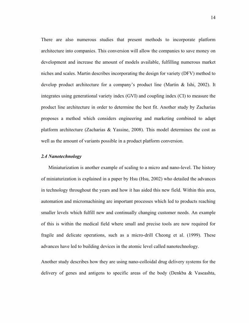
2.4 Nanotechnology
Miniaturization is another example of scaling to a micro and nano-level. The history
of miniaturization is explained in a paper by Hsu (Hsu, 2002) who detailed the advances
in technology throughout the years and how it has aided this new field. Within this area,
automation and micromachining are important processes which led to products reaching
smaller levels which fulfill new and continually changing customer needs. An example
of this is within the medical field where small and precise tools are now required for
fragile and delicate operations, such as a micro-drill Cheong et al. (1999). These
advances have led to building devices in the atomic level called nanotechnology.
Another study describes how they are using nano-colloidal drug delivery systems for the
delivery of genes and antigens to specific areas of the body (Denkba & Vaseashta,
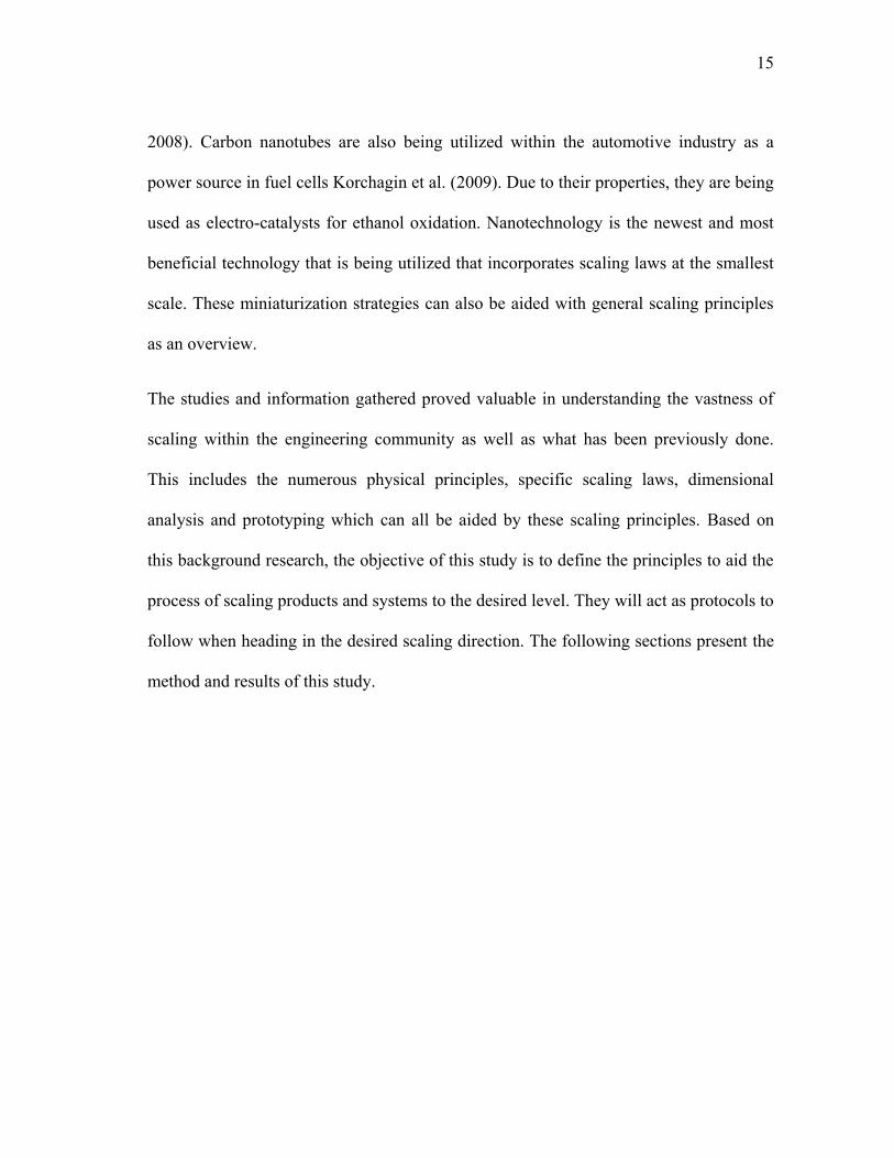
15
2008). Carbon nanotubes are also being utilized within the automotive industry as a
power source in fuel cells Korchagin et al. (2009). Due to their properties, they are being
used as electro-catalysts for ethanol oxidation. Nanotechnology is the newest and most
beneficial technology that is being utilized that incorporates scaling laws at the smallest
scale. These miniaturization strategies can also be aided with general scaling principles
as an overview.
The studies and information gathered proved valuable in understanding the vastness of
scaling within the engineering community as well as what has been previously done.
This includes the numerous physical principles, specific scaling laws, dimensional
analysis and prototyping which can all be aided by these scaling principles. Based on
this background research, the objective of this study is to define the principles to aid the
process of scaling products and systems to the desired level. They will act as protocols to
follow when heading in the desired scaling direction. The following sections present the
method and results of this study.
16
3. EMPIRICAL PRODUCT STUDY
The scaling principles were derived through an empirical research process which
incorporates searching, investigating and understanding example products and systems
in order to reveal product scale differences. These differences provide guidance for the
changes necessary when scaling a product, ultimately leading to the scaling principles
and two energy check lists.
3.1 Method
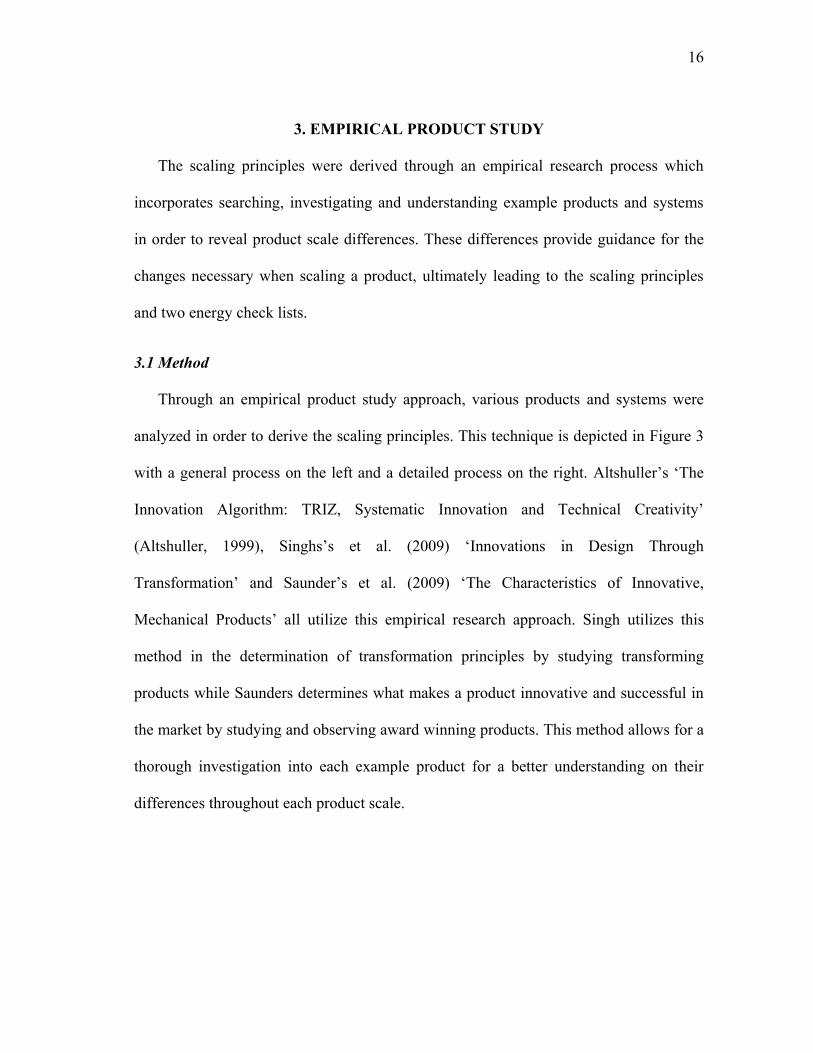
Through an empirical product study approach, various products and systems were
analyzed in order to derive the scaling principles. This technique is depicted in Figure 3
with a general process on the left and a detailed process on the right. Altshuller‟s „The
Innovation Algorithm: TRIZ, Systematic Innovation and Technical Creativity‟
(Altshuller, 1999), Singhs‟s et al. (2009) „Innovations in Design Through
Transformation‟ and Saunder‟s et al. (2009) „The Characteristics of Innovative,
Mechanical Products‟ all utilize this empirical research approach. Singh utilizes this
method in the determination of transformation principles by studying transforming
products while Saunders determines what makes a product innovative and successful in
the market by studying and observing award winning products. This method allows for a
thorough investigation into each example product for a better understanding on their
differences throughout each product scale.
17
Figure 3: General and detailed empirical research approach Singh et al. (2009)
Search for examples
through environmental
and internet search
Identify product classes
in order to locate
additional examples
Refine the product list
based upon product
selection criteria
Label examples by
power source, solutions
to functions, and
physical parameters
Compare products in
product classes
Derive principles and
sub-principles from
differences
Derive principles
Determine product scale
differences
Study products/
systems
Search products/
systems
General research
approach
Detailed research
approach
Determine how example
products work
18
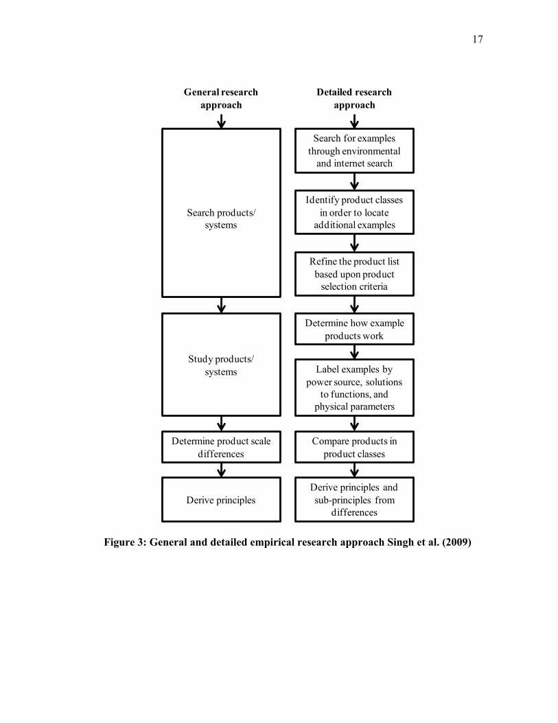
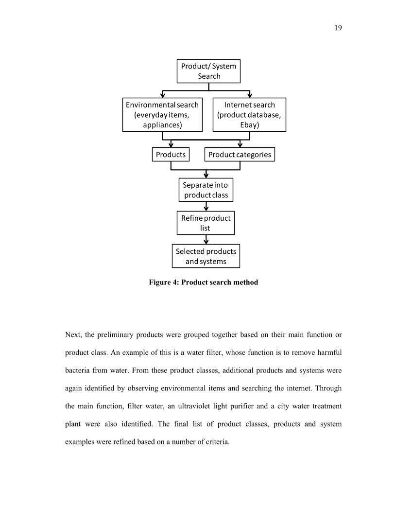
3.1.1 Product Identification and Search Method
Example products are necessary in the derivation of these scaling principles. The
search method for the products is shown in Figure 4. First, preliminary products were
selected by observing everyday environmental items. This involved searching for
products around the house, office and even the city, in order to determine a preliminary
list of items. Other means of determining preliminary products came from searching an
online product database, Ebay, an online merchandise auctioning website. It uses a
product category list to assist its users in finding their desired items. Searching through
this list for new products, additional items were identified. These items were categorized
based on general function, such as a nut cracker or coffee grinder, which allowed for a
broader spectrum of items to be determined. In some cases, product categories were
determined, such as agricultural equipment, which led to additional products such as a
combine harvester and grain harvester.
19
Figure 4: Product search method
Next, the preliminary products were grouped together based on their main function or
product class. An example of this is a water filter, whose function is to remove harmful
bacteria from water. From these product classes, additional products and systems were
again identified by observing environmental items and searching the internet. Through
the main function, filter water, an ultraviolet light purifier and a city water treatment
plant were also identified. The final list of product classes, products and system
examples were refined based on a number of criteria.
Product/ SystemSearch
Internet search(product database,
Ebay)
Environmental search(everyday items,
appliances)
Products Product categories
Separate into product class
Selected productsand systems
Refine productlist
20
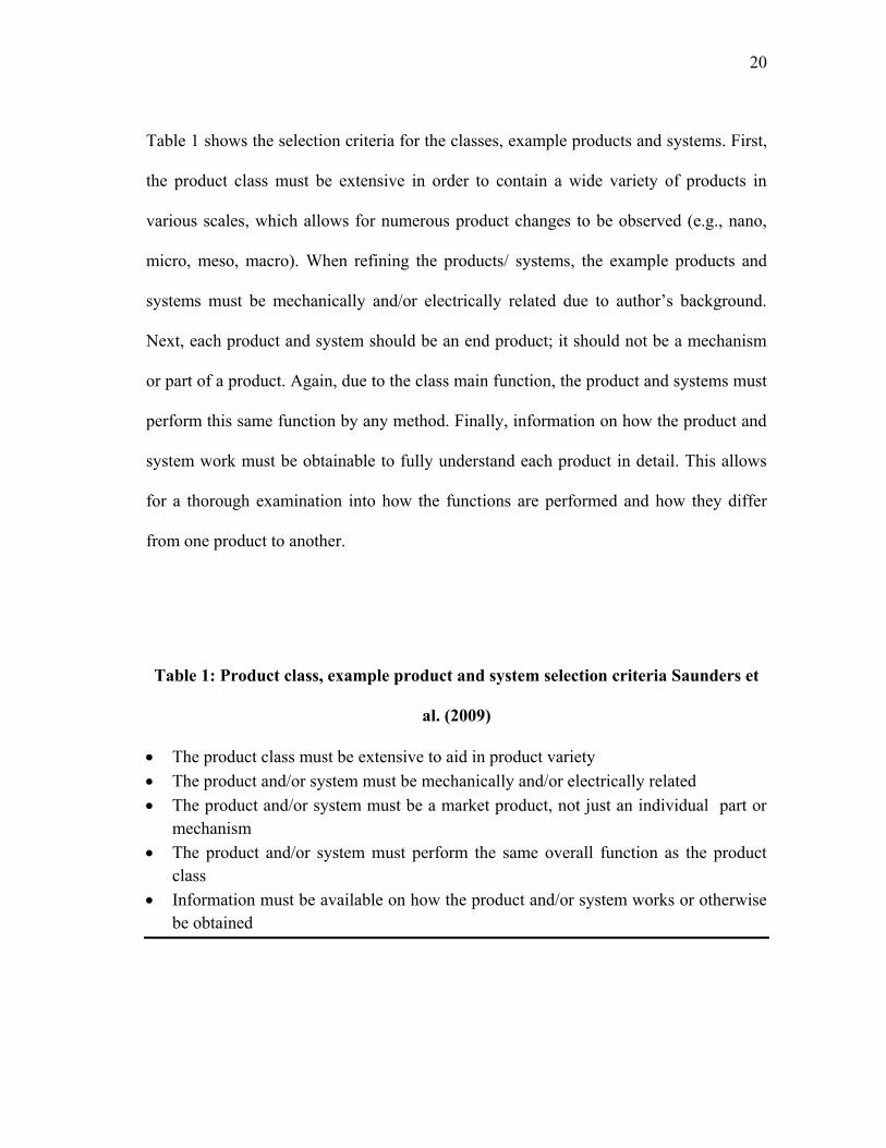
Table 1 shows the selection criteria for the classes, example products and systems. First,
the product class must be extensive in order to contain a wide variety of products in
various scales, which allows for numerous product changes to be observed (e.g., nano,
micro, meso, macro). When refining the products/ systems, the example products and
systems must be mechanically and/or electrically related due to author‟s background.
Next, each product and system should be an end product; it should not be a mechanism
or part of a product. Again, due to the class main function, the product and systems must
perform this same function by any method. Finally, information on how the product and
system work must be obtainable to fully understand each product in detail. This allows
for a thorough examination into how the functions are performed and how they differ
from one product to another.
Table 1: Product class, example product and system selection criteria Saunders et
al. (2009)
The product class must be extensive to aid in product variety
The product and/or system must be mechanically and/or electrically related
The product and/or system must be a market product, not just an individual part or
mechanism
The product and/or system must perform the same overall function as the product
class
Information must be available on how the product and/or system works or otherwise
be obtained
21
Once all products were refined based on the product selection criteria, 46 products and
systems were obtained. There were 17 total product classes, 12 contained three example
products and 5 classes contained 2 products. This list incorporates a wide variety of
product classes ranging from transporting dirt to making bread. It is extensive to provide
insights into the product differences in order to derive the general scaling principles.
3.1.2 Investigating Products
Example products are labeled based on their “energy source”, “solutions to
functions”, and “physical properties” to thoroughly understand how they work. The
majority of this research was again web based relying on websites such as How Stuff
Works, Google Search, Google Scholar and Texas A&M‟s online article library. This
online article search utilizes other article databases to find related studies to the search
entry. These databases include Academic Search Complete, Applied Science and
Technology Full Text, and Science Direct. A number of books were also utilized such as
How Stuff Works (Brain, 2001) and The New Way Things Work Macaulay et al. (1998).
“Energy source” in this study is defined as what powers a product or system. Through
observation, systems were divided into two categories, user and machine activity. An
example of a user activity is removing a pecan from the shell while a machine activity is
an electric nutcracker cracking the shell.
“Solutions to functions” relate to the products‟ overall function and sub-functions and
how they are performed. The overall function is defined as the main function being
performed, such as shelling for a shelling machine. Whereas the sub-functions are the
22
individual functions or steps necessary to fulfill the overall function, such as import nut,
form shell, export nut and separate nut from shell.
Products can also be separated into two categories, concurrent or non-concurrent
systems. A concurrent system is defined as a system which can perform multiple
functions at the same time; whereas a non-concurrent system is one that can only
perform one individual function at a time (Dictionary.com, 2011).
“Physical property” is defined as “any property used to characterize matter and energy
and their interactions” (Dictionary.com, 2001). This can be categorized into intensive
and extensive properties. Intensive properties are scale independent, such as hardness,
ductility, and elasticity. Extensive properties are scale dependent, such as stiffness,
volume, and mass. Extensive properties are altered when scaling is required and
intensive properties are not (Chemistry-Dictionary.com, 2011).
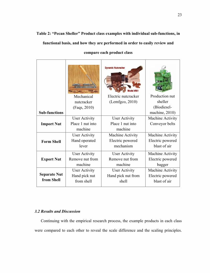
The three product characteristics, “energy source”, “solutions to functions” and
“physical properties”, were summarized into an outline for ease of comparison between
each product scale. The outline consisted of the main function performed, followed by
each sub-function, under which power source, solutions to functions, and physical
property for each product were under. The shelling machine outline is shown in Table 2
as an example with images of each mechanism. This method enabled the differences of
each product to be easily compared.
23
Table 2: “Pecan Sheller” Product class examples with individual sub-functions, in
functional basis, and how they are performed in order to easily review and
compare each product class
3.2 Results and Discussion
Continuing with the empirical research process, the example products in each class
were compared to each other to reveal the scale difference and the scaling principles.
Sub-functions
Mechanical
nutcracker
(Faqs, 2010)
Electric nutcracker
(Lemfgco, 2010)
Production nut
sheller
(Biodiesel-
machine, 2010)
Import Nut
User Activity
Place 1 nut into
machine
User Activity
Place 1 nut into
machine
Machine Activity
Conveyor belts
Form Shell
User Activity
Hand operated
lever
Machine Activity
Electric powered
mechanism
Machine Activity
Electric powered
blast of air
Export Nut
User Activity
Remove nut from
machine
User Activity
Remove nut from
machine
Machine Activity
Electric powered
bagger
Separate Nut
from Shell
User Activity
Hand pick nut
from shell
User Activity
Hand pick nut from
shell
Machine Activity
Electric powered
blast of air
24
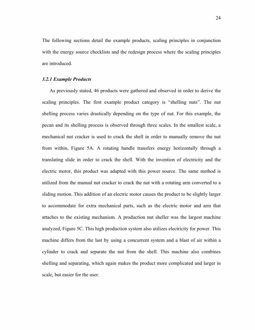
The following sections detail the example products, scaling principles in conjunction
with the energy source checklists and the redesign process where the scaling principles
are introduced.
3.2.1 Example Products
As previously stated, 46 products were gathered and observed in order to derive the
scaling principles. The first example product category is “shelling nuts”. The nut
shelling process varies drastically depending on the type of nut. For this example, the
pecan and its shelling process is observed through three scales. In the smallest scale, a
mechanical nut cracker is used to crack the shell in order to manually remove the nut
from within, Figure 5A. A rotating handle transfers energy horizontally through a
translating slide in order to crack the shell. With the invention of electricity and the
electric motor, this product was adapted with this power source. The same method is
utilized from the manual nut cracker to crack the nut with a rotating arm converted to a
sliding motion. This addition of an electric motor causes the product to be slightly larger
to accommodate for extra mechanical parts, such as the electric motor and arm that
attaches to the existing mechanism. A production nut sheller was the largest machine
analyzed, Figure 5C. This high production system also utilizes electricity for power. This
machine differs from the last by using a concurrent system and a blast of air within a
cylinder to crack and separate the nut from the shell. This machine also combines
shelling and separating, which again makes the product more complicated and larger in
scale, but easier for the user.
25
A. B. C.
Figure 5: Examples of pecan shelling machines A. Manual nut cracker (Faqs, 2010),
B. Electric nut cracker (Lemfgco, 2010), C. Production shelling machine (Biodiesel-
machine, 2010)
Table 3 depicts the full list of example products and systems utilized to determine the
scaling principles.
Table 3: Comparison products
Saw
a) Hand saw
b) Electric circular saw
c) Gasoline powered chainsaw
Trencher
a) Pull plow
b) Gasoline push trencher
c) Gasoline ride trencher
Length Measurer
a) 12 inch ruler
b) Tape measure

26
Table 3: Continued
c) Laser tape
Building
a) Wooden building
b) Concrete building
c) Metal and glass skyscraper
Dirt Transport
a) Push wheelbarrow
b) Dump truck
c) Earth mover
Cut metal
a) Hand shears
b) Bandsaw
c) Plasma cutter
Excavate Earth
a) Shovel
b) Backhoe Excavator
c) Dragline excavator
Water Filtration
a) Water bag filter
b) Uv light purifier
c) City water treatment plant
Tell Time
a) Mechanical wrist watch
b) Electric wrist watch
Weight Scale
a) Balance
b) Mechanical weight scale
c) Load cell truck scale
27
Table 3: Continued
Grain Harvesting
a) Scythe
b) Grain harvester
Bread Making
a) Hand kneading
b) Production bread making
c) Electric home bread maker
Cotton Picking
a) Hand picking cotton
b) Cotton picker
Press
a) Mechanical vice
b) Hydraulic press
c) 100 ton press
Air pump
a) Hand operated air pump
b) Air compressor
Secure items
a) Combination lock
b) Safe
3.2.2 Determining Product Scale Differences
Repeated patterns were recognized throughout the product scales, which led to the
derivation of the scaling principles. The first four principles were realized from the
“solutions to functions” portion of the product summary. This section was important in
28
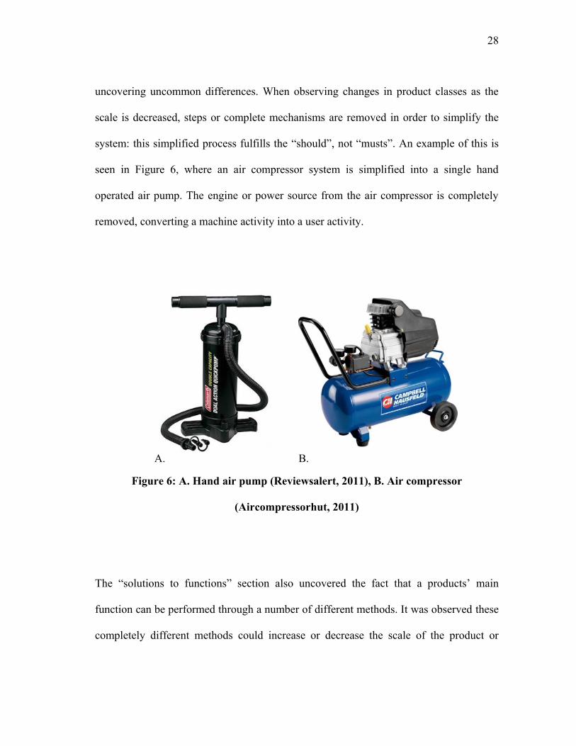
uncovering uncommon differences. When observing changes in product classes as the
scale is decreased, steps or complete mechanisms are removed in order to simplify the
system: this simplified process fulfills the “should”, not “musts”. An example of this is
seen in Figure 6, where an air compressor system is simplified into a single hand
operated air pump. The engine or power source from the air compressor is completely
removed, converting a machine activity into a user activity.
A. B.
Figure 6: A. Hand air pump (Reviewsalert, 2011), B. Air compressor
(Aircompressorhut, 2011)
The “solutions to functions” section also uncovered the fact that a products‟ main
function can be performed through a number of different methods. It was observed these
completely different methods could increase or decrease the scale of the product or
29
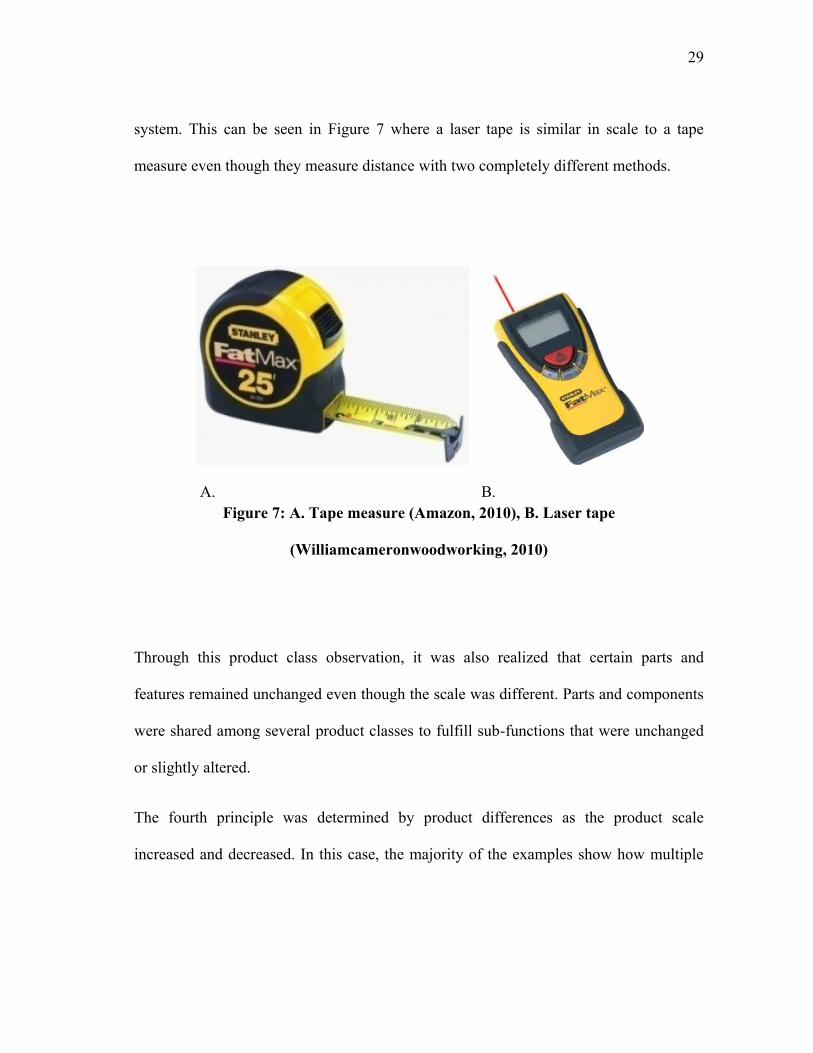
system. This can be seen in Figure 7 where a laser tape is similar in scale to a tape
measure even though they measure distance with two completely different methods.
A. B.
Figure 7: A. Tape measure (Amazon, 2010), B. Laser tape
(Williamcameronwoodworking, 2010)
Through this product class observation, it was also realized that certain parts and
features remained unchanged even though the scale was different. Parts and components
were shared among several product classes to fulfill sub-functions that were unchanged
or slightly altered.
The fourth principle was determined by product differences as the product scale
increased and decreased. In this case, the majority of the examples show how multiple
30
manual steps are combined into one automatic system. Functions and sub-functions were
also combined when scaling was decreased.
The “energy source” category of the product summary revealed the next scaling
principle, which was expected. In the majority of the product groups, both user and
machine activity systems were employed, where user activities were typically found in
smaller scales and machine activities in larger scales. In some cases, a product might be
scaled and designed for users without electricity or gasoline. In this case, natural
resources available to the user must be utilized as an energy source, such as a nearby
river.
The last principle relates to the physical differences in each product class, which was
again expected. The size and material of the product, depending on the necessary
capacity, is altered to suit each need. Topological changes were also noticed with the
various placements of certain parts. With this realization, parameter change was the last
principle created. These principles could not have been generated without these example
products. Their span throughout the product scale helped in realizing the sub-principles
as well.
3.2.3 Scaling Principles
Through our empirical product research method, six scaling principles were derived:
„change energy source‟, „simplify system‟, „change method‟, „combine functions‟,
„directly transfer components‟ and „change parameters‟. A description of each principle
31
and energy source checklist supporting the „change energy source‟ principle is described
in detail in the following sections.
Change energy source- Change energy source to a more efficient means or to better
fulfill the desired customer needs and design constraints. Change a user activity into a
machine activity. Use available natural resources when applicable.
There are many energy sources available to power products and machines. First, human
energy by the user can be utilized. This is typically found with smaller and lower cost
products. When rivers or similar natural resources are available, they can be taken
advantage of by users who do not have the luxuries of electricity or gasoline. An
example of this is using a water mill to grind corn. When other energy sources such as
electricity and fossil fuels are accessible, they allow products to be automatically run,
increasing production and efficiency. These energy sources are typically used to power
larger scaled products and machines. However, there are certain factors that need to be
considered before choosing an energy source. These factors are related to the customer
needs and design constraints required for the product, which is what determines the best
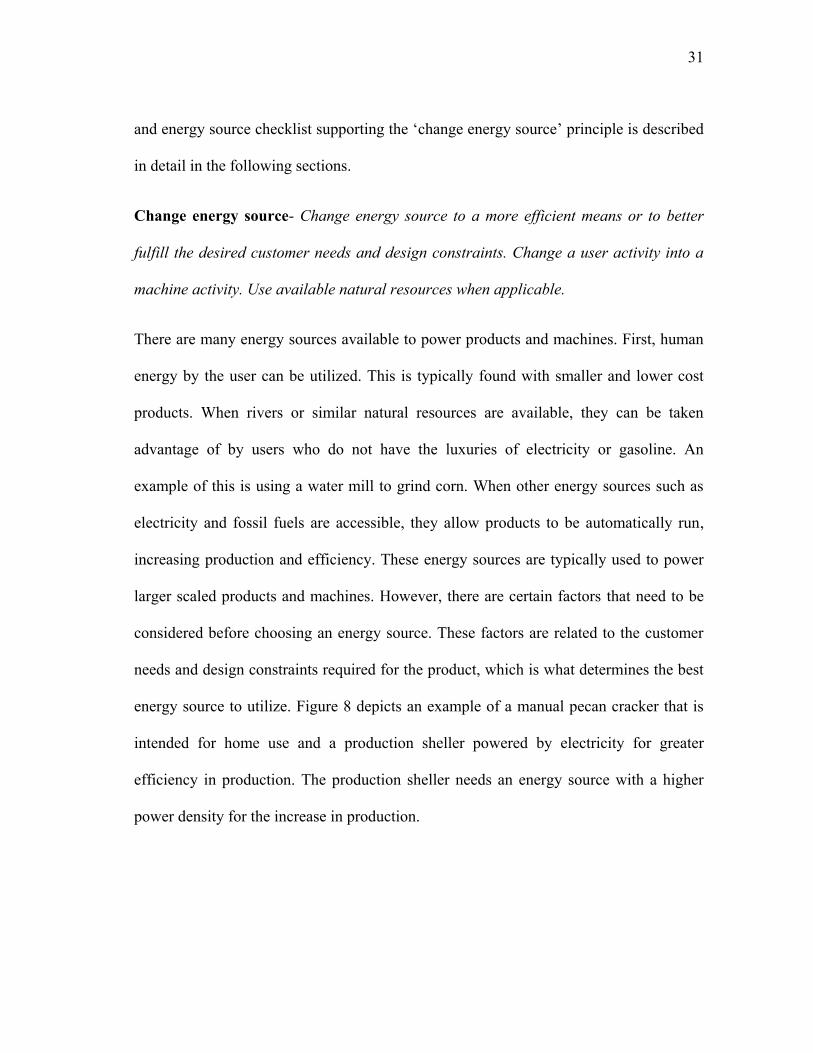
energy source to utilize. Figure 8 depicts an example of a manual pecan cracker that is
intended for home use and a production sheller powered by electricity for greater
efficiency in production. The production sheller needs an energy source with a higher
power density for the increase in production.
32
A. B.
Figure 8: Examples “change energy source” A. Mechanical nutcracker powered by
the user (Faqs, 2010), B. Conversion to an electric production shelling machine
(Biodiesel-machine, 2010)
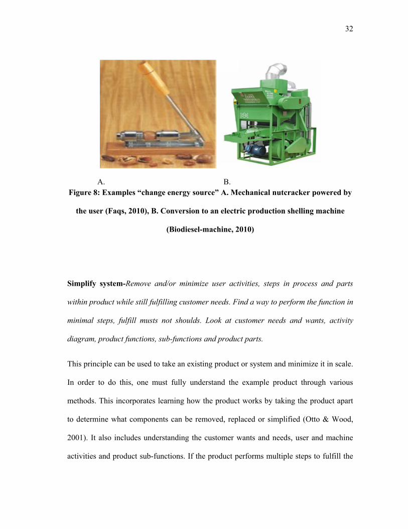
Simplify system-Remove and/or minimize user activities, steps in process and parts
within product while still fulfilling customer needs. Find a way to perform the function in
minimal steps, fulfill musts not shoulds. Look at customer needs and wants, activity
diagram, product functions, sub-functions and product parts.
This principle can be used to take an existing product or system and minimize it in scale.
In order to do this, one must fully understand the example product through various
methods. This incorporates learning how the product works by taking the product apart
to determine what components can be removed, replaced or simplified (Otto & Wood,
2001). It also includes understanding the customer wants and needs, user and machine
activities and product sub-functions. If the product performs multiple steps to fulfill the
33
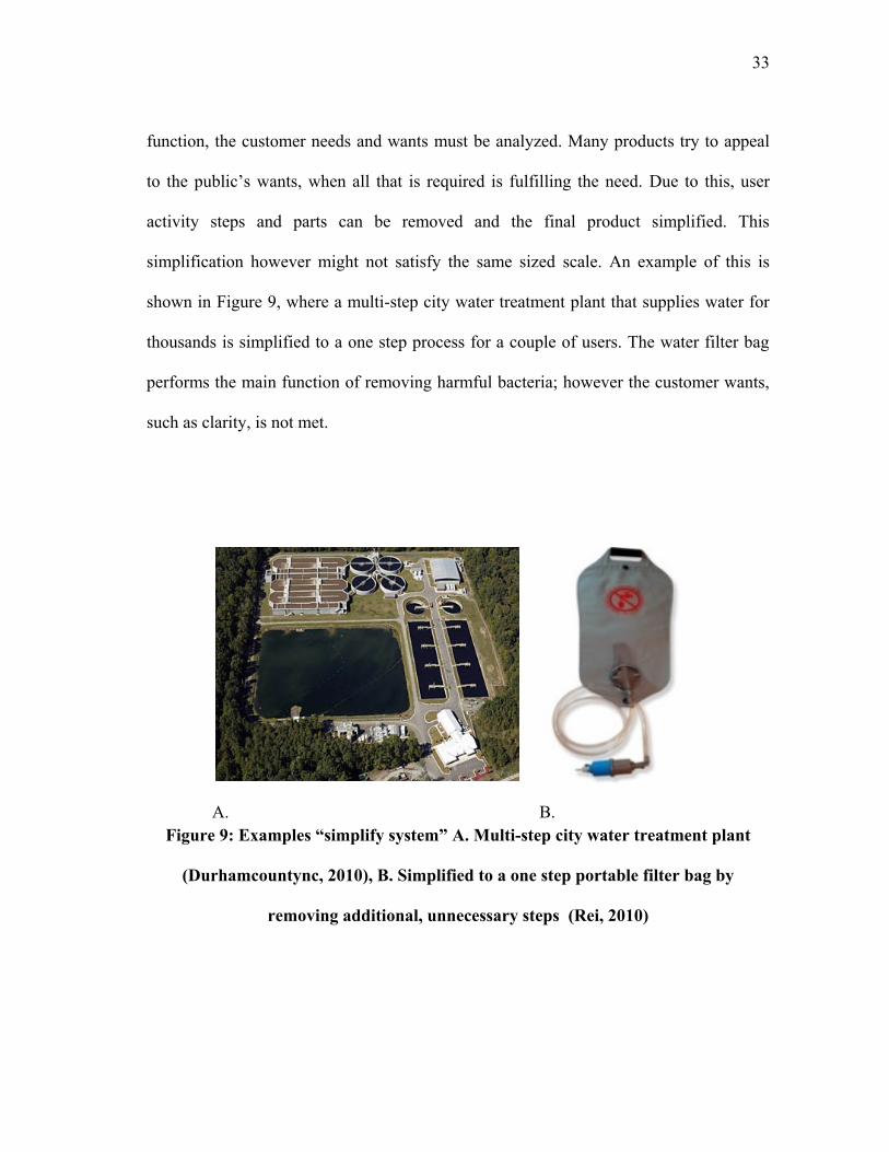
function, the customer needs and wants must be analyzed. Many products try to appeal
to the public‟s wants, when all that is required is fulfilling the need. Due to this, user
activity steps and parts can be removed and the final product simplified. This
simplification however might not satisfy the same sized scale. An example of this is
shown in Figure 9, where a multi-step city water treatment plant that supplies water for
thousands is simplified to a one step process for a couple of users. The water filter bag
performs the main function of removing harmful bacteria; however the customer wants,
such as clarity, is not met.
A. B.
Figure 9: Examples “simplify system” A. Multi-step city water treatment plant
(Durhamcountync, 2010), B. Simplified to a one step portable filter bag by
removing additional, unnecessary steps (Rei, 2010)
34
Change method- Find an alternate method to perform the same function/sub-function to
better fulfill customer needs. Change a user activity into a machine activity. Change the
process that performs the function (e.g., physical to chemical). Design a new way to
perform the current function, new technology. Adapt an existing product system/
mechanism to fulfill the current function. Look at customer needs and wants, activity
diagram, product functions and sub-functions and product parts.
This principle incorporates determining other possible solutions and ideas to the overall
design problem as well as individual product functions and user activities. One way this
can be accomplished is by using an existing product mechanism directly or through
modification to perform the current function. An example of this is modifying a rotating
potato peeler to string a guitar. Another way is to determine whether the function can be
performed by changing the general process (e.g., a physical process converted to
chemical). A completely new method can also be engineered to perform the desired
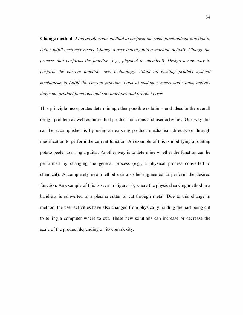
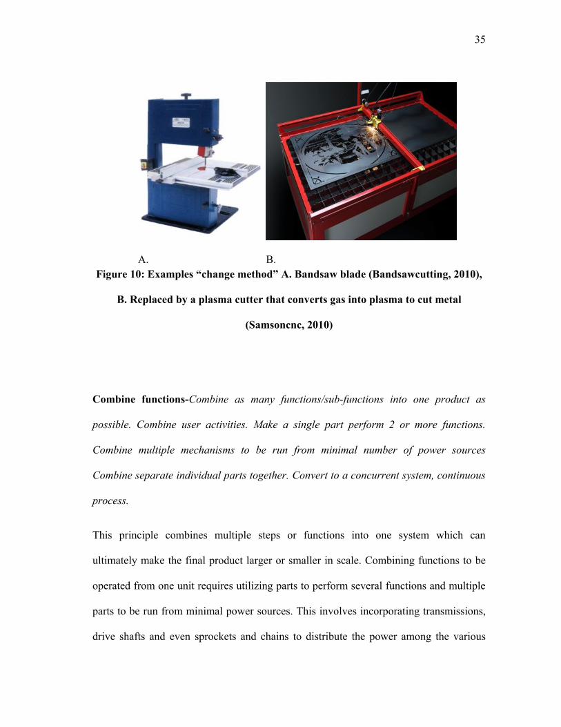
function. An example of this is seen in Figure 10, where the physical sawing method in a
bandsaw is converted to a plasma cutter to cut through metal. Due to this change in
method, the user activities have also changed from physically holding the part being cut
to telling a computer where to cut. These new solutions can increase or decrease the
scale of the product depending on its complexity.
35
A. B.
Figure 10: Examples “change method” A. Bandsaw blade (Bandsawcutting, 2010),
B. Replaced by a plasma cutter that converts gas into plasma to cut metal
(Samsoncnc, 2010)
Combine functions-Combine as many functions/sub-functions into one product as
possible. Combine user activities. Make a single part perform 2 or more functions.
Combine multiple mechanisms to be run from minimal number of power sources
Combine separate individual parts together. Convert to a concurrent system, continuous
process.
This principle combines multiple steps or functions into one system which can
ultimately make the final product larger or smaller in scale. Combining functions to be
operated from one unit requires utilizing parts to perform several functions and multiple
parts to be run from minimal power sources. This involves incorporating transmissions,
drive shafts and even sprockets and chains to distribute the power among the various
36
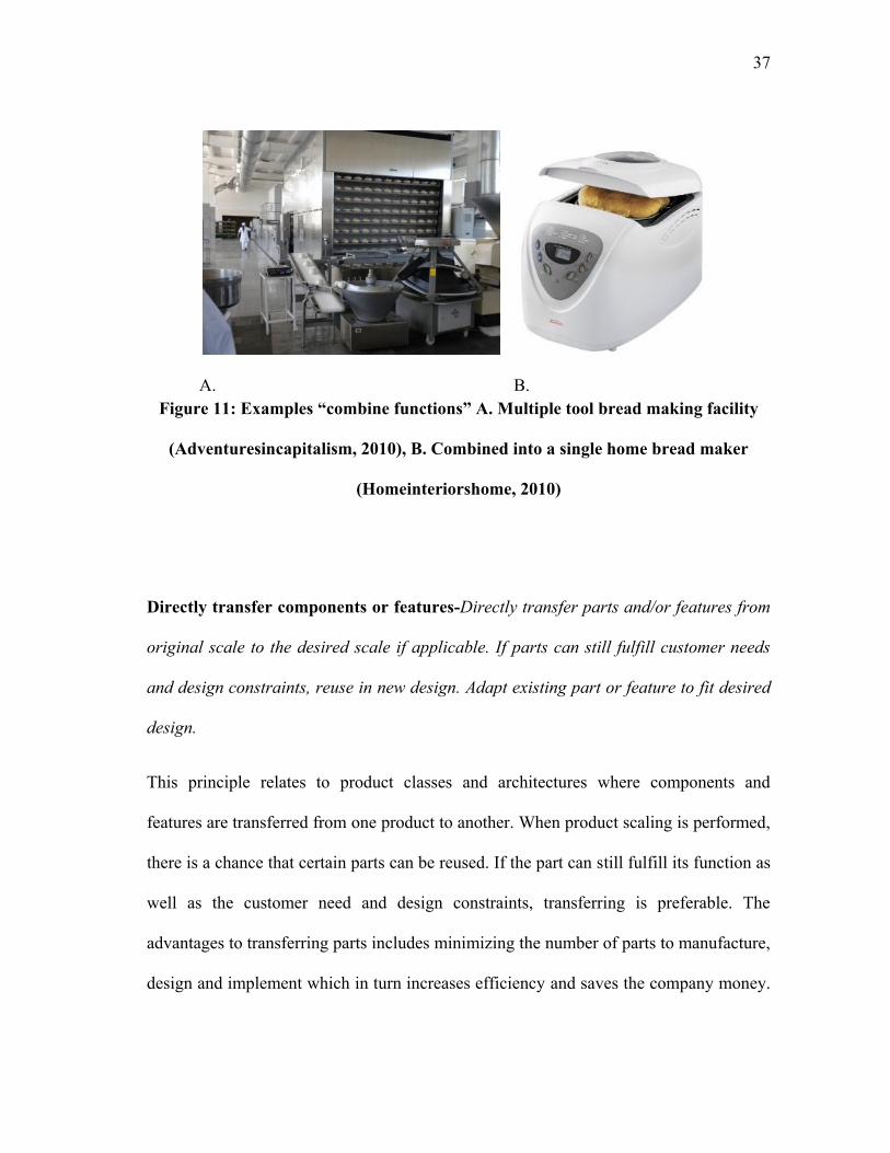
mechanisms. This allows for several moving systems to be powered from one motor,
removing additional motors and saving space. Combining user activities also serves as a
way to minimize the amount of user activities. If two functions can be combined, the
product will require less input from the user, saving time. An example of “combine
functions” is seen in Figure 11, where the bread making process requires the user to
perform multiple activities and utilize multiple appliances, such as a mixer and oven.
This process is combined into a single home bread maker that uses one rotating paddle to
mix as well as knead the ingredients in one unit. This unit also contains a heating
element in order to bake the bread where it was mixed. User activities such as hand
mixing and kneading also decrease after converting the process to a machine activity.
This smaller product fulfills the same function, however at a different production scale.
Combining functions can be aided by the addition of a concurrent process. This can be
utilized in order for all functions to be performed at the same time. Conveyor systems
can be implemented to help this process along by allowing a seamless transfer from one
function to the next, making the process continuous.
37
A. B.
Figure 11: Examples “combine functions” A. Multiple tool bread making facility
(Adventuresincapitalism, 2010), B. Combined into a single home bread maker
(Homeinteriorshome, 2010)
Directly transfer components or features-Directly transfer parts and/or features from
original scale to the desired scale if applicable. If parts can still fulfill customer needs
and design constraints, reuse in new design. Adapt existing part or feature to fit desired
design.
This principle relates to product classes and architectures where components and
features are transferred from one product to another. When product scaling is performed,
there is a chance that certain parts can be reused. If the part can still fulfill its function as
well as the customer need and design constraints, transferring is preferable. The
advantages to transferring parts includes minimizing the number of parts to manufacture,
design and implement which in turn increases efficiency and saves the company money.
38
It also allows the company to produce a wider amount of products to appeal to different
customers Simpson et al. (2001). This principle can be applied to both scaling up or
down; however the scale change is typically small. Greater changes of scale would
incorporate many more drastic changes to parts and features. Transferring would not be
suitable in these cases.
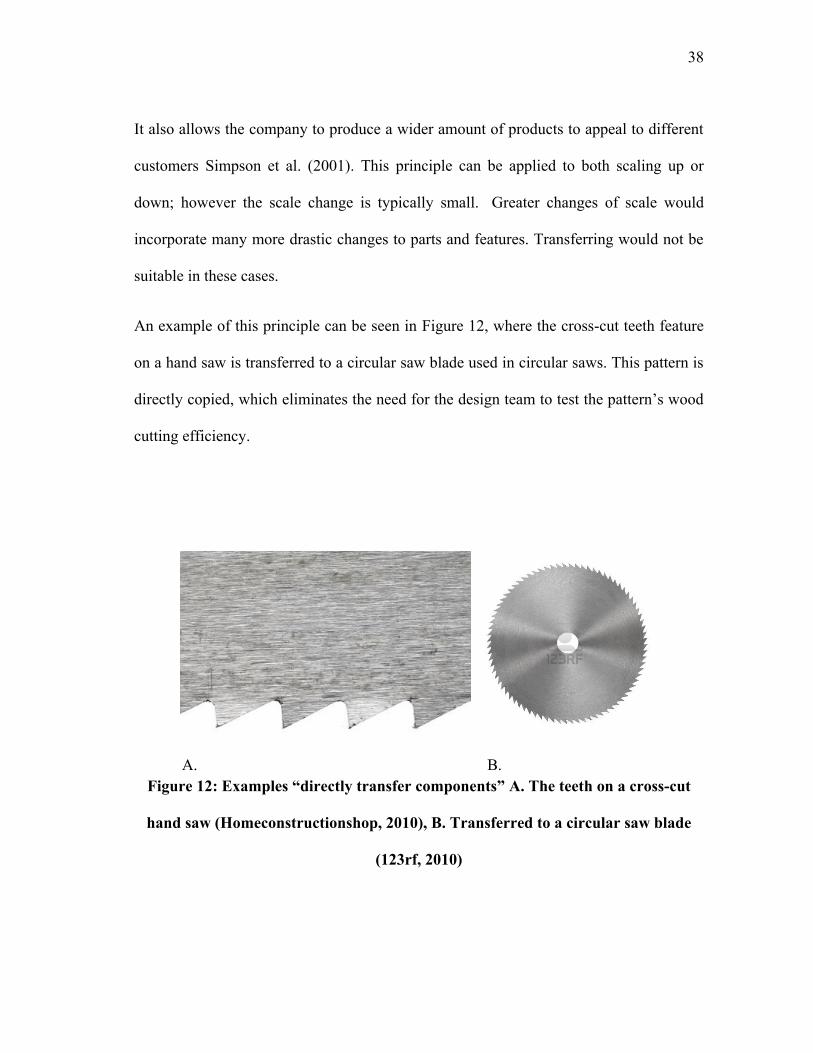
An example of this principle can be seen in Figure 12, where the cross-cut teeth feature
on a hand saw is transferred to a circular saw blade used in circular saws. This pattern is
directly copied, which eliminates the need for the design team to test the pattern‟s wood
cutting efficiency.
A. B.
Figure 12: Examples “directly transfer components” A. The teeth on a cross-cut
hand saw (Homeconstructionshop, 2010), B. Transferred to a circular saw blade
(123rf, 2010)
39
Change parameters - Change material and/or physical parameters of individual parts
to fulfill new customer needs. Change extensive properties (scale variant) to sustain new
capacity loads. Change the physical location of individual parts to better fulfill customer
needs.
This principle observes the material properties as well as the physical scale of the overall
product and its parts and the changes that are necessary to accommodate the desired
capacity loads. Material selection is an important factor when designing a new product.
Depending on the product‟s function and customer needs, the material choices can vary
tremendously. From a lightweight portable hand drill made of metal and plastic to an all
steel dump truck, the materials must meet the desired requirements. The capacity load
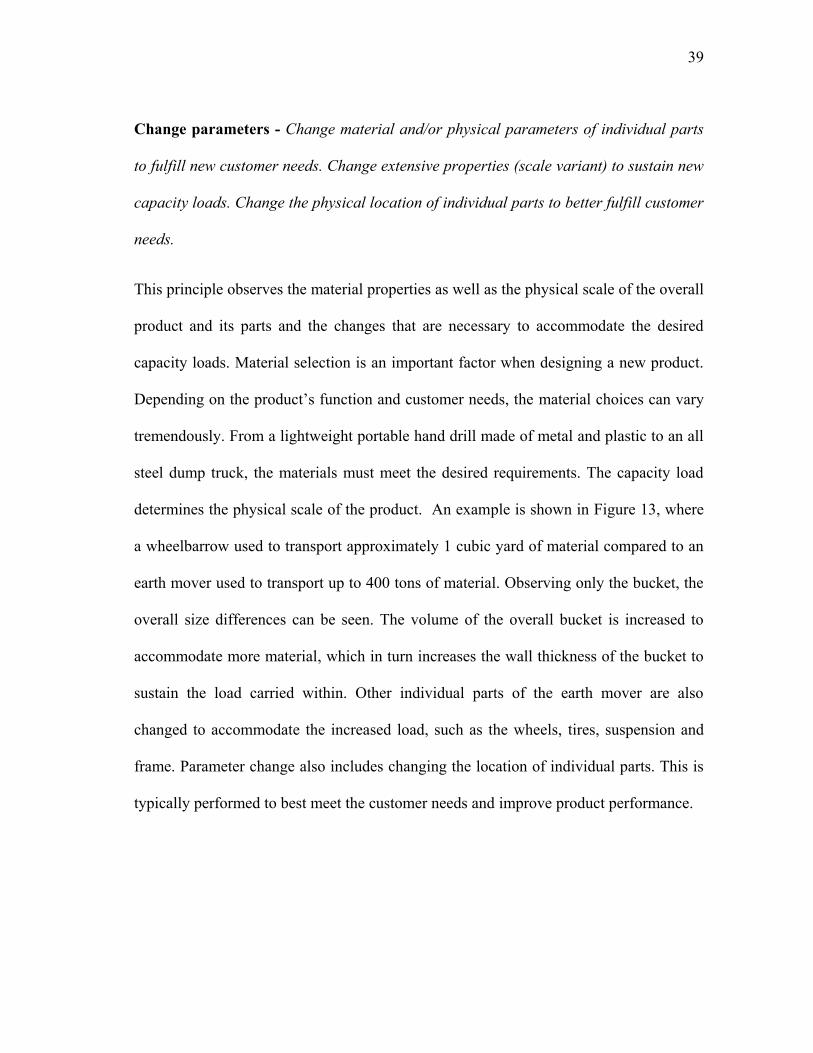
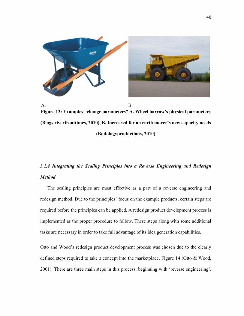
determines the physical scale of the product. An example is shown in Figure 13, where
a wheelbarrow used to transport approximately 1 cubic yard of material compared to an
earth mover used to transport up to 400 tons of material. Observing only the bucket, the
overall size differences can be seen. The volume of the overall bucket is increased to
accommodate more material, which in turn increases the wall thickness of the bucket to
sustain the load carried within. Other individual parts of the earth mover are also
changed to accommodate the increased load, such as the wheels, tires, suspension and
frame. Parameter change also includes changing the location of individual parts. This is
typically performed to best meet the customer needs and improve product performance.
40
A. B.
Figure 13: Examples “change parameters” A. Wheel barrow‟s physical parameters
(Blogs.riverfronttimes, 2010), B. Increased for an earth mover‟s new capacity needs
(Budologyproductions, 2010)
3.2.4 Integrating the Scaling Principles into a Reverse Engineering and Redesign
Method
The scaling principles are most effective as a part of a reverse engineering and
redesign method. Due to the principles‟ focus on the example products, certain steps are
required before the principles can be applied. A redesign product development process is
implemented as the proper procedure to follow. These steps along with some additional
tasks are necessary in order to take full advantage of its idea generation capabilities.
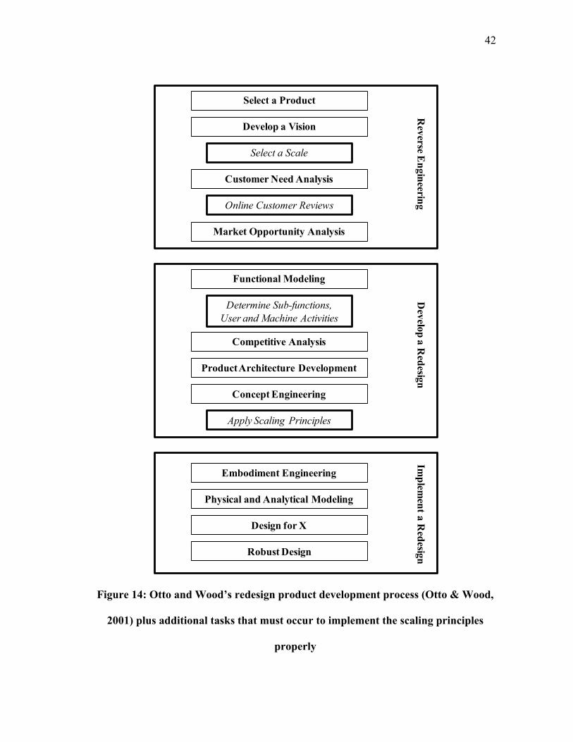
Otto and Wood‟s redesign product development process was chosen due to the clearly
defined steps required to take a concept into the marketplace, Figure 14 (Otto & Wood,
2001). There are three main steps in this process, beginning with „reverse engineering‟.
41
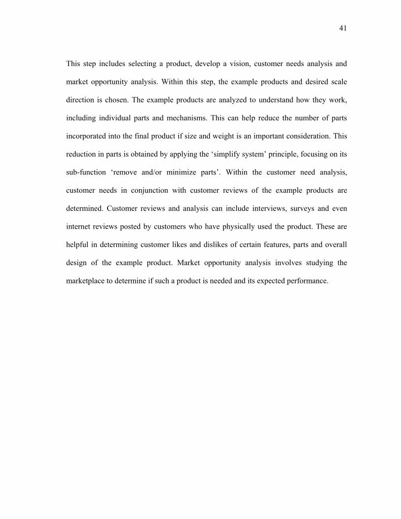
This step includes selecting a product, develop a vision, customer needs analysis and
market opportunity analysis. Within this step, the example products and desired scale
direction is chosen. The example products are analyzed to understand how they work,
including individual parts and mechanisms. This can help reduce the number of parts
incorporated into the final product if size and weight is an important consideration. This
reduction in parts is obtained by applying the „simplify system‟ principle, focusing on its
sub-function „remove and/or minimize parts‟. Within the customer need analysis,
customer needs in conjunction with customer reviews of the example products are
determined. Customer reviews and analysis can include interviews, surveys and even
internet reviews posted by customers who have physically used the product. These are
helpful in determining customer likes and dislikes of certain features, parts and overall
design of the example product. Market opportunity analysis involves studying the
marketplace to determine if such a product is needed and its expected performance.
42
Figure 14: Otto and Wood‟s redesign product development process (Otto & Wood,
2001) plus additional tasks that must occur to implement the scaling principles
properly
Select a Product
Develop a Vision
Customer Need Analysis
Market Opportunity Analysis
Functional Modeling
Competitive Analysis
Product Architecture Development
Concept Engineering
Embodiment Engineering
Physical and Analytical Modeling
Design for X
Robust Design
Rev
erse En
gin
eering
Dev
elop
a R
edesig
nIm
plem
ent a
Red
esign
Select a Scale
Online Customer Reviews
Determine Sub-functions,
User and Machine Activities
Apply Scaling Principles
43
„Develop a redesign‟ is the next step which incorporates functional modeling,
competitive analysis, product architecture development and concept engineering. The
main function as well as the sub-functions are derived within the functional modeling
step. This is important for the application of the „combine functions‟, „change method‟
and „simplify system‟ principles. Through an understanding of the products‟ sub-
functions, the realization that a number of these sub-functions can be combined will be
apparent when scaling down. User and machine activities must also be determined for
„simplify system‟ and „change method‟. Through the creation of an activity diagram,
user activities are clearly exposed. This can help reduce the number of user activities
involved with handling the product. With these tasks completed, the scaling principles
and energy source checklists can be implemented in the „concept engineering‟ step. This
is the proper placement for these principles since the example products are now
completely understood and deconstructed. These principles serve as a principle-based
idea generation method similar to TIPS/TRIZ, Wordtree and other concept generation
aids. The scaling principles should be used in conjunction with these existing idea
generation methods in order to generate the most ideas and innovative products.
The last step in the redesign process is „implement a redesign‟, which incorporates
embodiment engineering, physical and analytical modeling, design for X and robust
design. This is the proper procedure that must be followed in order to apply the scaling
principles. With these steps and scaling principles accomplished, the final concept will
fulfill and possibly surpass the design requirements.
44
3.2.5 Energy Sources
The proper energy source to power a product or system is an important aspect for an
engineer or designer to consider. However, choosing the best one that fulfills the design
constraints and customer needs can sometimes be difficult. In order to aid this process,
two checklists were established that are based on customer needs in conjunction with the
“change energy source” principle to help choose the best combination of solutions.
These energy source checklists were derived by observing the example products as well
as studying literature about incorporating energy in engineering design (Otto & Wood,
2001). From the example products, it was obvious that energy sources could first be
separated into human powered and automatic. Table 4 shows the two energy source
checklists, beginning with human powered. This checklist is valuable in determining
solutions for a design problem which requires a manual or human powered solution.
This is common when a product is scaled down to be hand operated or sold at a cheaper
price. A possible design problem which would benefit from this checklist is developing a
transportation system for someone who is handicapped. By studying the checklist, one or
possibly two mechanisms acted upon by a body part can be chosen to propel the user
where they desire.

45
Table 4: Energy source checklist (Mechanism and energy types based on Otto &
Wood, 2001)
Human powered
Body part
Arm operated
Leg operated
Torso operated
Neck operated
Shoulder operated
Knee operated
Mechanism Type
Rotational
Translational
Vibration
Energy Transfer Type
Direct
Indirect (storage)
Gravity
Pendulum
Spring
Flywheel
Hydraulic accumulator
CAES, pneumatic
Energy Conversion - Electricity
Direct
Indirect (storage)
Capacitor

46
Table 4: Continued
Automatic
Energy Type
Renewable
Wind
Water
Solar
Geothermal
Direct
Indirect (storage)
Electricity
Battery
Plug in
Direct
Indirect (storage)
Mechanical
Rotational
Translational
Vibrational
Fossil Fuels
Acoustic
Biological
Chemical
Hydraulic
Magnetic
Pneumatic
Radioactive
Thermal
Direct
Indirect (storage)
47
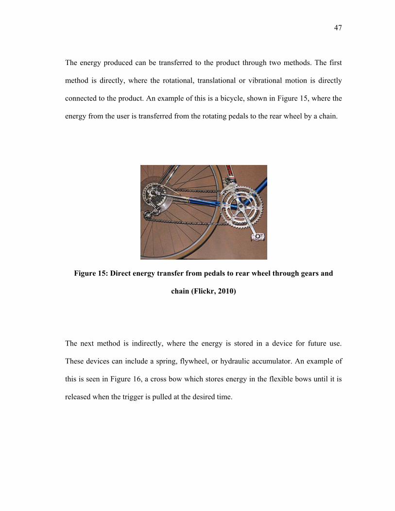
The energy produced can be transferred to the product through two methods. The first
method is directly, where the rotational, translational or vibrational motion is directly
connected to the product. An example of this is a bicycle, shown in Figure 15, where the
energy from the user is transferred from the rotating pedals to the rear wheel by a chain.
Figure 15: Direct energy transfer from pedals to rear wheel through gears and
chain (Flickr, 2010)
The next method is indirectly, where the energy is stored in a device for future use.
These devices can include a spring, flywheel, or hydraulic accumulator. An example of
this is seen in Figure 16, a cross bow which stores energy in the flexible bows until it is
released when the trigger is pulled at the desired time.

48
Figure 16: Energy stored in flexible bows until released by trigger (Crankyfarmer,
2010)
Products can also be powered independently, one energy source, or as a combination of
energy sources. This typically includes converting human power or mechanical energy
into electrical. This is done through the use of a generator which is what performs the
energy conversion. Figure 17 depicts a flashlight which is powered by manual action in
order to produce and store electrical energy for future use. This type of system it
typically used when electricity or an electric source is not available.
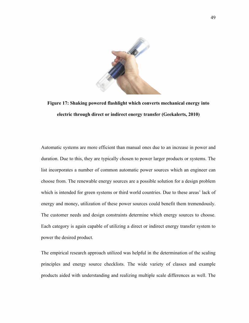
49
Figure 17: Shaking powered flashlight which converts mechanical energy into
electric through direct or indirect energy transfer (Geekalerts, 2010)
Automatic systems are more efficient than manual ones due to an increase in power and
duration. Due to this, they are typically chosen to power larger products or systems. The
list incorporates a number of common automatic power sources which an engineer can
choose from. The renewable energy sources are a possible solution for a design problem
which is intended for green systems or third world countries. Due to these areas‟ lack of
energy and money, utilization of these power sources could benefit them tremendously.
The customer needs and design constraints determine which energy sources to choose.
Each category is again capable of utilizing a direct or indirect energy transfer system to
power the desired product.
The empirical research approach utilized was helpful in the determination of the scaling
principles and energy source checklists. The wide variety of classes and example
products aided with understanding and realizing multiple scale differences as well. The

50
scaling principles in conjunction with the energy source checklists and redesign process
can improve design efficiency and the original products‟ performance.
51
4. COMPARATIVE CASE STUDY
A preliminary test for the scaling principles and revised redesign process is
undertaking a comparative case study which involves solving a design problem;
designing a portable golf transportation system to carry the user and golf bag. This case
study has the ability to validate these principles as a viable idea generation method for
product scaling. The following section presents a comparison between the process
utilized by a senior design team that solved the design problem previously and the
scaling method. The scaling principles are then applied to both example product scales
by which ideas are generated and a final design is developed. The final concept is then
compared to the senior design teams‟ concept to understand how the scaling principles
affect the overall performance of the design.
The undertaken case study was based on a previous design problem from
undergraduate senior design. This problem was previously solved by a team of seniors
from The University of Texas Pan-American, which included the thesis author. The
proposed problem was designing a portable golf transportation system to transport both
the user and golf bag. This design problem was chosen based on the ability to compare
the final concepts using a typical design process and the redesign method applying the
scaling principles. The comparison can show how the scaling principles affect the
number of ideas generated and the performance of the final design. Another reason for
choosing this problem is because the scaling principles could be applied in two
directions, scaling up from the push cart and scaling down from the golf cart. The last
reason for choosing this problem is due to minimal solutions in this desired product
52
scale. The example products must be utilized in order to generate ideas and an overall
design.
The customer needs for this design problem are:
• Carry an average size person (190 lbs.)
• Carry an average size golf bag (35 lbs.)
• Securely hold golf bag
• Portable/Compact (fit in average size car trunk, 15 cubic ft.)
• Safe
4.1 Senior Design and Redesign Process Comparison
The previous design method utilized by the undergraduate senior design team was
one based on a typical design process. The team based this process on designing an
original product, not a redesign of an existing product. This process utilizes similar steps
from the reverse engineering method/ scaling design process; however there are also
differences. Figure 18 shows both processes in detail.
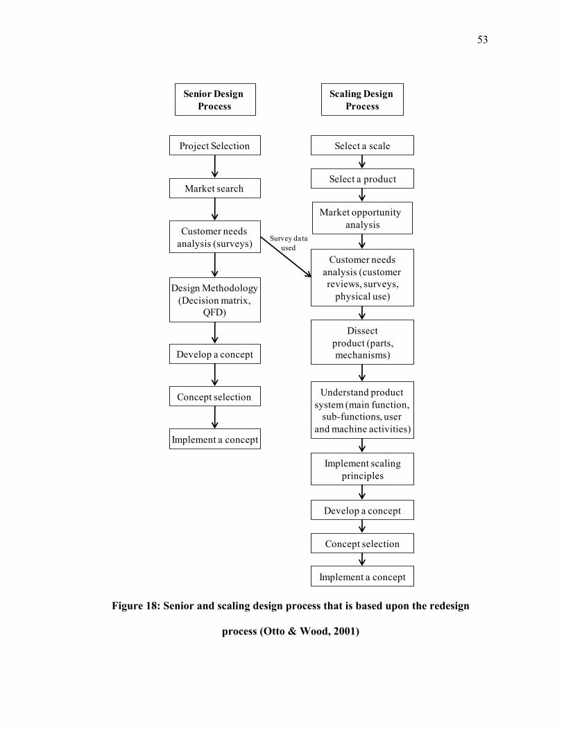
53
Figure 18: Senior and scaling design process that is based upon the redesign
process (Otto & Wood, 2001)
Market search
Design Methodology
(Decision matrix,
QFD)
Concept selection
Project Selection
Customer needs
analysis (surveys)
Develop a concept
Implement a concept
Select a product
Customer needs
analysis (customer
reviews, surveys,
physical use)
Dissect
product (parts,
mechanisms)
Understand product
system (main function,
sub-functions, user
and machine activities)
Implement scaling
principles
Market opportunity
analysis
Select a scale
Senior Design
Process
Scaling Design
Process
Concept selection
Develop a concept
Implement a concept
Survey data
used
54
Both processes begin with developing an idea on which the design problem is based
upon. In the scaling process, this step incorporates selecting example products as well as
the desired scale. The next shared step is market search. This step incorporates
researching other products and designs in order to understand what is currently on the
market and whether there is a need for such a product. Next, a customer needs analysis is
performed to determine whether users would purchase such a product and if they did
what they would like in the product. This is performed through surveys, interviews and
other similar methods. The senior design process utilized surveys which were passed out
at local golf courses in order to determine if such a product is wanted. This survey can
be seen in the Appendix G. The results from this survey were also utilized in the scaling
process for better understanding customer needs and wants. For the scaling process,
additional online customer reviews were researched on the example products to further
aid in understanding customer likes and dislikes. This additional step was performed due
to the redesign process.
The senior design process continues to design methodology, including a decision matrix
and quality function deployment. The decision matrix aided in comparing the customer
wants to determine which was most important, Appendix H. The QFD table correlates
wants to engineering specifications or requirements in order to establish targets in which
can be met. The next step in the senior design process jumps to idea generation or
develop a concept. The method utilized by the senior design team to generate concepts
was based on an overall picture. A complete concept was developed which limited the
amount of ideas generated. Very few ideas were specific to parts and mechanisms which
55
differed greatly to the scaling process. Due to the close observations of the scaling
products, a lot of ideas were generated for specific parts and features. This again is due
to the scaling principles and the focus on the scaled product.
The scaling process continues with understanding the example products. These products
are researched and deconstructed in order to fully understand how they work. This
includes physically studying, examining, and tearing the example products apart. Each
example product is decomposed into sub-mechanisms followed by individual parts. The
main function, sub-functions as well as machine and user activities are also determined
in order to take full advantage of the scaling principles. Once the product is fully studied,
the scaling principles can be applied to all aspects of the example products; sub-
functions, parts, user and machine activates. The scaling principles are applied within the
idea generation step. This step can also utilize additional idea generation methods such
as mind maps and TRIZ to gain supplementary ideas. From this step on, both processes
incorporate the same design and development steps. These include develop a concept,
concept selection and implement a concept. The scaling process is similar to the typical
design process; however additional detailed actions must be taken to implement the
principles correctly.
4.2 Small Scale
Due to the desired scale, in between two distinct product scales, the principles can be
applied in two directions. The scaling method is first applied to the small scale products
followed by the application of the principles and details on the generated ideas.
56
4.2.1 The Scaling Method with Small Scale Products
Following the redesign process, choosing the best scaling products was the first step.
Due to developing a design from two different scales, the small scale products were
looked at first. The products chosen from this category are manual and electric push
carts. Both manual and electric carts were picked to scale from in order to fully
understand this product class. Both have their advantages and disadvantages that are
taken into account to develop the best design possible.
An internet search was performed in order to find these products. Using Google search,
searches were made for „golf push carts‟ and „electric golf push carts‟. This led to
websites such as Golfsmith.com, Thesandtrap.com and Criticalgolf.com which provided
many variations of carts as well as their customer reviews. These reviews proved
valuable in understanding what customers liked and disliked about their push carts. The
scaling products reviewed were the Clicgear Model 3.0, Sun Mountain 2010 Micro cart
and Tour Trek Tahoe push cart, all seen in Table 5. The Clicgear and Tour Trek models
both have three wheels while the Sun Mountain model has four, the two typical
configurations in design for push carts on the market. Based on the reviews from
Golfsmith.com, the Clicgear and Sun Mountain carts were the highest ranked with
almost 5 stars (Golfsmith, 2011). Table 5 also shows what features and aspects of the
scaling carts are liked by the customers. This is taken into great consideration when
generating ideas for the final concept.
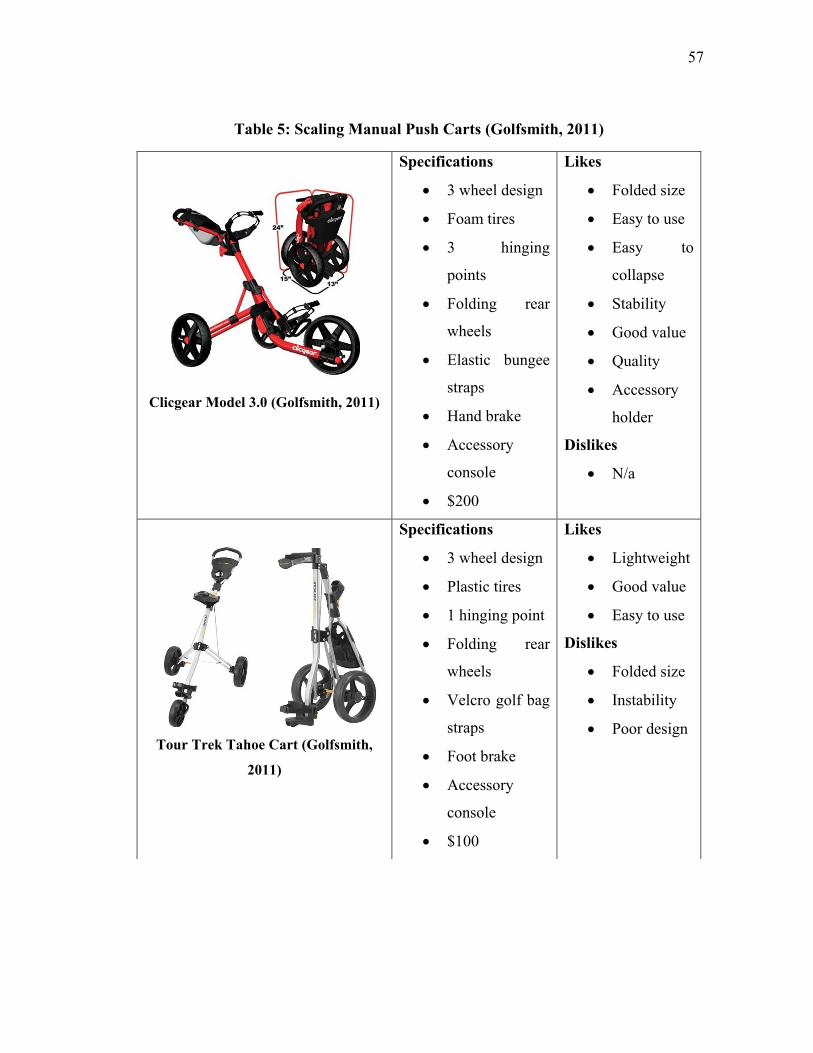
57
Table 5: Scaling Manual Push Carts (Golfsmith, 2011)
Clicgear Model 3.0 (Golfsmith, 2011)
Specifications
3 wheel design
Foam tires
3 hinging
points
Folding rear
wheels
Elastic bungee
straps
Hand brake
Accessory
console
$200
Likes
Folded size
Easy to use
Easy to
collapse
Stability
Good value
Quality
Accessory
holder
Dislikes
N/a
Tour Trek Tahoe Cart (Golfsmith,
2011)
Specifications
3 wheel design
Plastic tires
1 hinging point
Folding rear
wheels
Velcro golf bag
straps
Foot brake
Accessory
console
$100
Likes
Lightweight
Good value
Easy to use
Dislikes
Folded size
Instability
Poor design
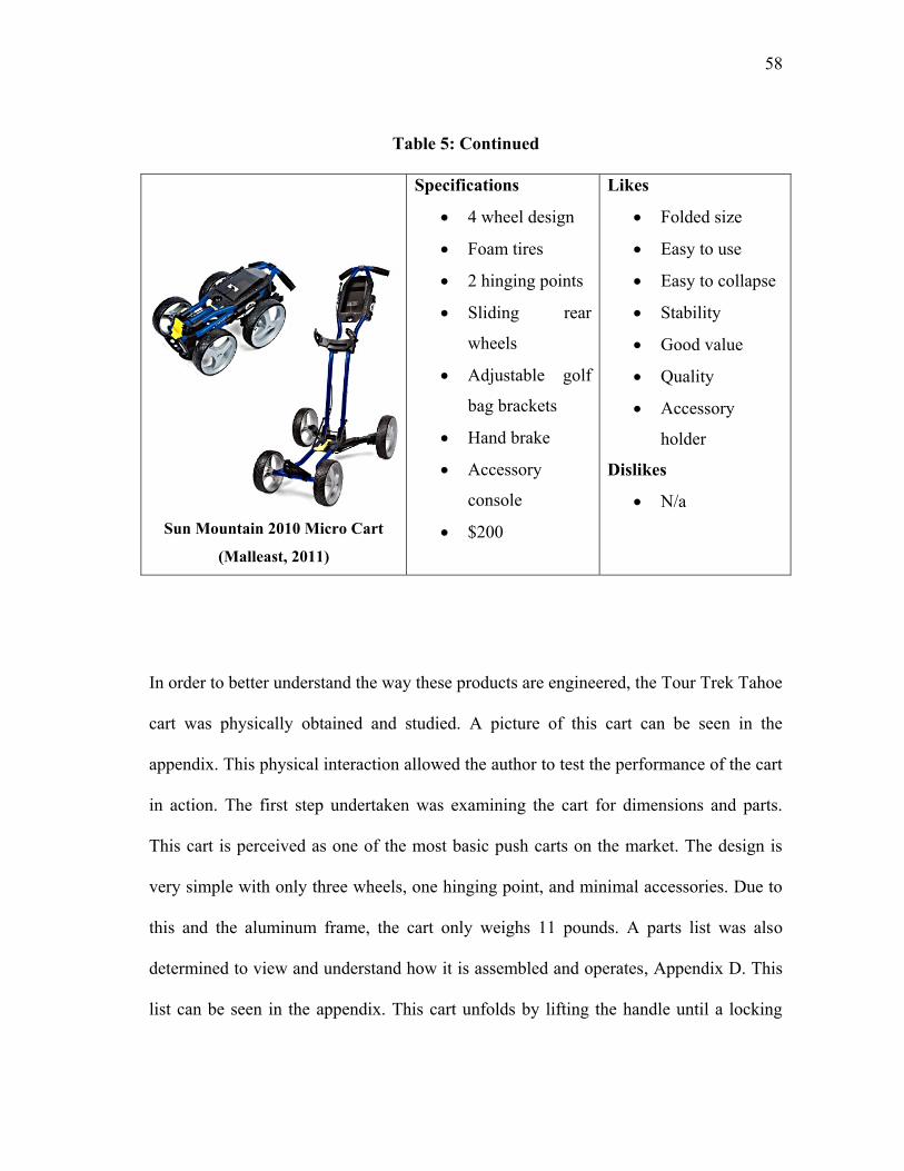
58
Table 5: Continued
Sun Mountain 2010 Micro Cart
(Malleast, 2011)
Specifications
4 wheel design
Foam tires
2 hinging points
Sliding rear
wheels
Adjustable golf
bag brackets
Hand brake
Accessory
console
$200
Likes
Folded size
Easy to use
Easy to collapse
Stability
Good value
Quality
Accessory
holder
Dislikes
N/a
In order to better understand the way these products are engineered, the Tour Trek Tahoe
cart was physically obtained and studied. A picture of this cart can be seen in the
appendix. This physical interaction allowed the author to test the performance of the cart
in action. The first step undertaken was examining the cart for dimensions and parts.
This cart is perceived as one of the most basic push carts on the market. The design is
very simple with only three wheels, one hinging point, and minimal accessories. Due to
this and the aluminum frame, the cart only weighs 11 pounds. A parts list was also
determined to view and understand how it is assembled and operates, Appendix D. This
list can be seen in the appendix. This cart unfolds by lifting the handle until a locking
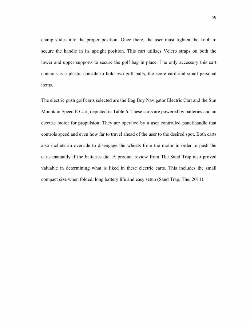
59
clamp slides into the proper position. Once there, the user must tighten the knob to
secure the handle in its upright position. This cart utilizes Velcro straps on both the
lower and upper supports to secure the golf bag in place. The only accessory this cart
contains is a plastic console to hold two golf balls, the score card and small personal
items.
The electric push golf carts selected are the Bag Boy Navigator Electric Cart and the Sun
Mountain Speed E Cart, depicted in Table 6. These carts are powered by batteries and an
electric motor for propulsion. They are operated by a user controlled panel/handle that
controls speed and even how far to travel ahead of the user to the desired spot. Both carts
also include an override to disengage the wheels from the motor in order to push the
carts manually if the batteries die. A product review from The Sand Trap also proved
valuable in determining what is liked in these electric carts. This includes the small
compact size when folded, long battery life and easy setup (Sand Trap, The, 2011).
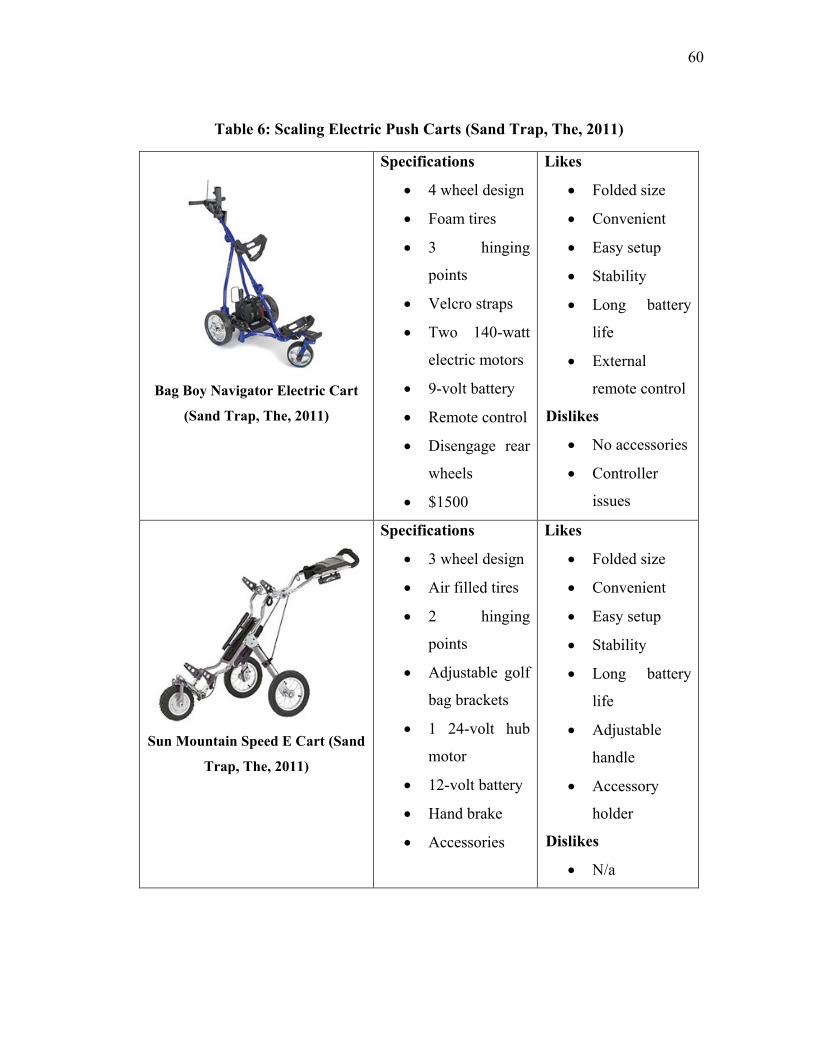
60
Table 6: Scaling Electric Push Carts (Sand Trap, The, 2011)
Bag Boy Navigator Electric Cart
(Sand Trap, The, 2011)
Specifications
4 wheel design
Foam tires
3 hinging
points
Velcro straps
Two 140-watt
electric motors
9-volt battery
Remote control
Disengage rear
wheels
$1500
Likes
Folded size
Convenient
Easy setup
Stability
Long battery
life
External
remote control
Dislikes
No accessories
Controller
issues
Sun Mountain Speed E Cart (Sand
Trap, The, 2011)
Specifications
3 wheel design
Air filled tires
2 hinging
points
Adjustable golf
bag brackets
1 24-volt hub
motor
12-volt battery
Hand brake
Accessories
Likes
Folded size
Convenient
Easy setup
Stability
Long battery
life
Adjustable
handle
Accessory
holder
Dislikes
N/a
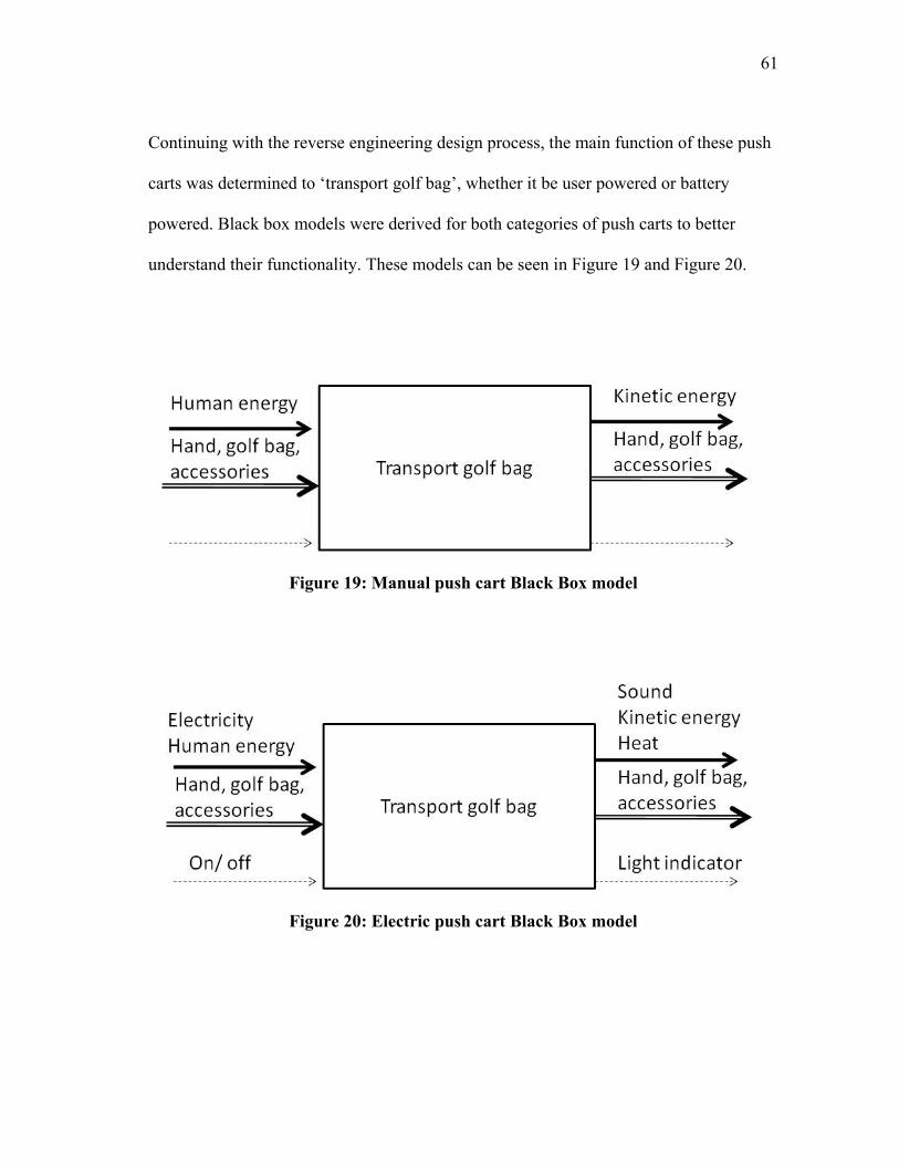
61
Continuing with the reverse engineering design process, the main function of these push
carts was determined to „transport golf bag‟, whether it be user powered or battery
powered. Black box models were derived for both categories of push carts to better
understand their functionality. These models can be seen in Figure 19 and Figure 20.
Figure 19: Manual push cart Black Box model
Figure 20: Electric push cart Black Box model

62
Both manual and electric push carts have identical material and signal input and outputs.
The differences between the two are seen in the energy input and output flows. The
manual push cart includes human energy as the input and kinetic energy as the output.
The electric push cart adds electricity and human energy as inputs and sound, kinetic
energy and heat as outputs.
With the overall function of both manual and electric push carts obtained, sub-functions
as well as user and machine activities were determined, Table 7 and Table 8.
Table 7: Manual push cart sub-functions
• Expand to full size
o Pull out legs and handle - user activity
o Slide and tighten locking clamp- user activity
• Hold golf bag
o Strap in golf bag (Velcro)- user activity
• Transport golf bag around course
o Push and pull of cart- user activity
o Push and release parking brake- user activity
• Fold to compact size
o Loosen clamp and slide up- user activity
o Pull legs and handle together - user activity
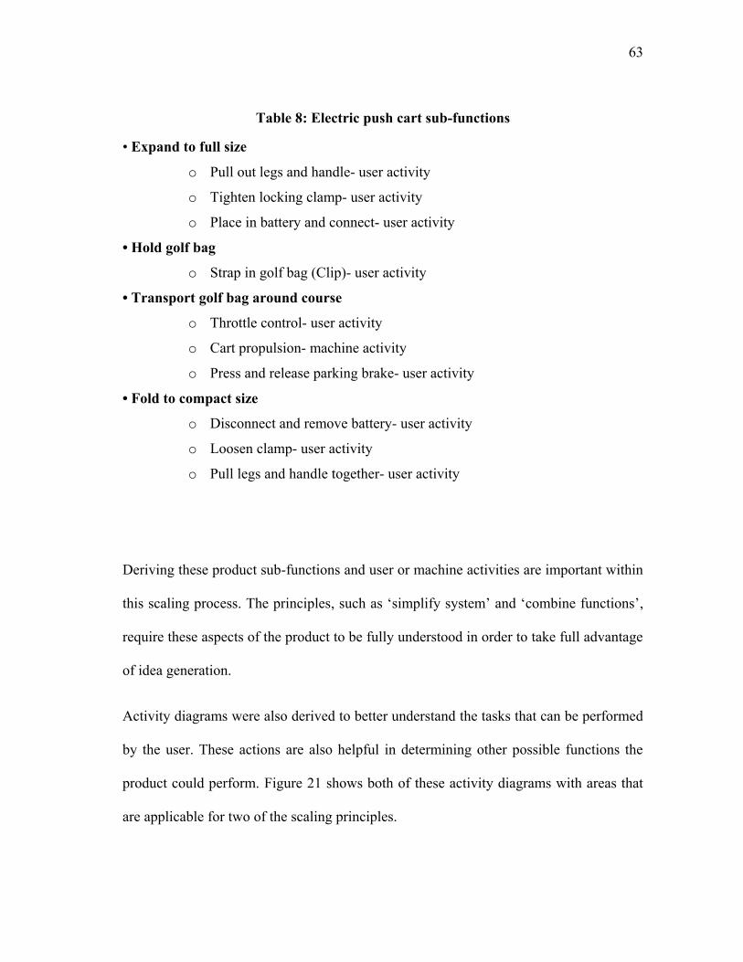
63
Table 8: Electric push cart sub-functions
• Expand to full size
o Pull out legs and handle- user activity
o Tighten locking clamp- user activity
o Place in battery and connect- user activity
• Hold golf bag
o Strap in golf bag (Clip)- user activity
• Transport golf bag around course
o Throttle control- user activity
o Cart propulsion- machine activity
o Press and release parking brake- user activity
• Fold to compact size
o Disconnect and remove battery- user activity
o Loosen clamp- user activity
o Pull legs and handle together- user activity
Deriving these product sub-functions and user or machine activities are important within
this scaling process. The principles, such as „simplify system‟ and „combine functions‟,
require these aspects of the product to be fully understood in order to take full advantage
of idea generation.
Activity diagrams were also derived to better understand the tasks that can be performed
by the user. These actions are also helpful in determining other possible functions the
product could perform. Figure 21 shows both of these activity diagrams with areas that
are applicable for two of the scaling principles.
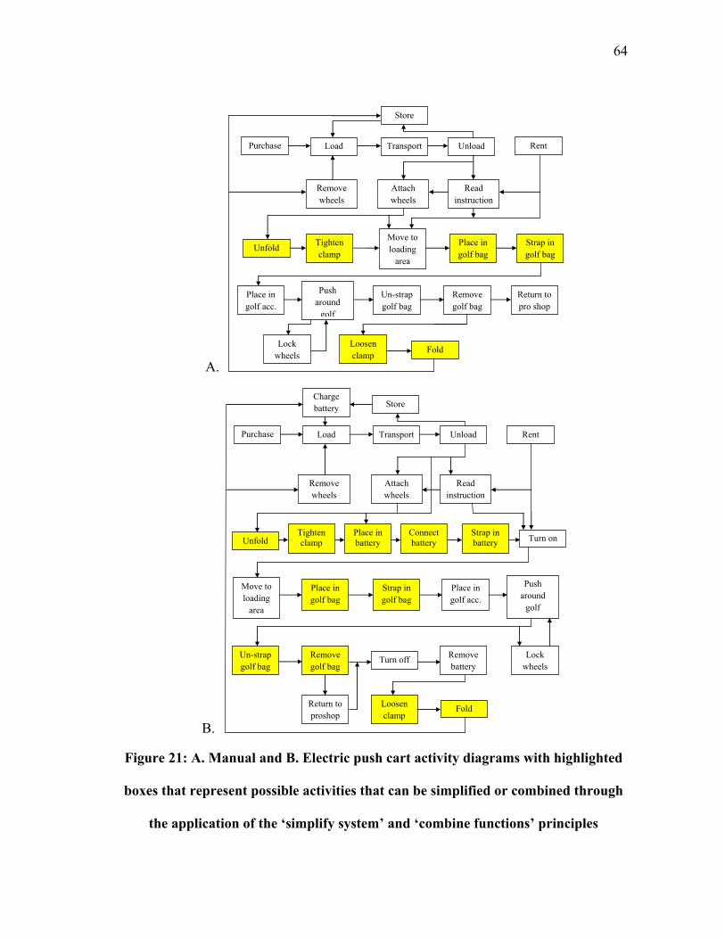
64
A.
B.
Figure 21: A. Manual and B. Electric push cart activity diagrams with highlighted
boxes that represent possible activities that can be simplified or combined through
the application of the „simplify system‟ and „combine functions‟ principles
Purchase Load Transport Unload
Move to
loading
area
Read
instruction
s
Unfold Place in
golf bag
Strap in
golf bag
Place in
golf acc.
Push
around
golf
course
Fold
Remove
golf bag
Un-strap
golf bag
Store
Rent
Tighten
clamp
Loosen
clamp
Attach
wheels
Remove
wheels
Return to
pro shop
Lock
wheels
Purchase Load Transport Unload
Move to
loading
area
Read
instruction
s
Unfold
Place in
golf bag
Strap in
golf bag
Place in
golf acc.
Push
around
golf
course
Fold
Remove
golf bag
Un-strap
golf bag
Store
Turn on Place in
battery
Rent
Tighten
clamp
Loosen
clamp
Charge
battery
Turn off
Attach
wheels
Remove
wheels
Return to
proshop
Lock
wheels
Remove
battery
Connect
battery
Strap in
battery
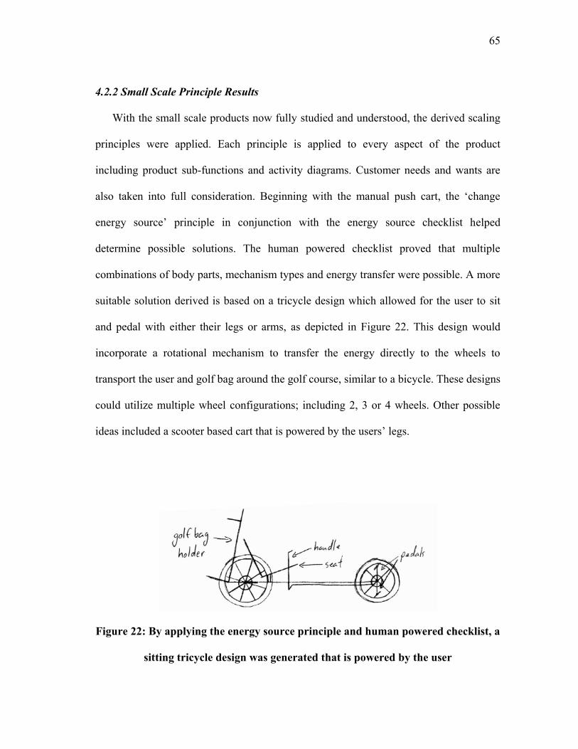
65
4.2.2 Small Scale Principle Results
With the small scale products now fully studied and understood, the derived scaling
principles were applied. Each principle is applied to every aspect of the product
including product sub-functions and activity diagrams. Customer needs and wants are
also taken into full consideration. Beginning with the manual push cart, the „change
energy source‟ principle in conjunction with the energy source checklist helped
determine possible solutions. The human powered checklist proved that multiple
combinations of body parts, mechanism types and energy transfer were possible. A more
suitable solution derived is based on a tricycle design which allowed for the user to sit
and pedal with either their legs or arms, as depicted in Figure 22. This design would
incorporate a rotational mechanism to transfer the energy directly to the wheels to
transport the user and golf bag around the golf course, similar to a bicycle. These designs
could utilize multiple wheel configurations; including 2, 3 or 4 wheels. Other possible
ideas included a scooter based cart that is powered by the users‟ legs.
Figure 22: By applying the energy source principle and human powered checklist, a
sitting tricycle design was generated that is powered by the user
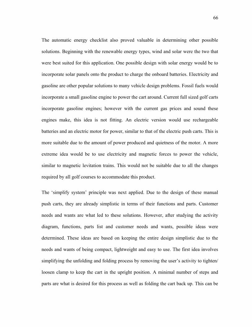
66
The automatic energy checklist also proved valuable in determining other possible
solutions. Beginning with the renewable energy types, wind and solar were the two that
were best suited for this application. One possible design with solar energy would be to
incorporate solar panels onto the product to charge the onboard batteries. Electricity and
gasoline are other popular solutions to many vehicle design problems. Fossil fuels would
incorporate a small gasoline engine to power the cart around. Current full sized golf carts
incorporate gasoline engines; however with the current gas prices and sound these
engines make, this idea is not fitting. An electric version would use rechargeable
batteries and an electric motor for power, similar to that of the electric push carts. This is
more suitable due to the amount of power produced and quietness of the motor. A more
extreme idea would be to use electricity and magnetic forces to power the vehicle,
similar to magnetic levitation trains. This would not be suitable due to all the changes
required by all golf courses to accommodate this product.
The „simplify system‟ principle was next applied. Due to the design of these manual
push carts, they are already simplistic in terms of their functions and parts. Customer
needs and wants are what led to these solutions. However, after studying the activity
diagram, functions, parts list and customer needs and wants, possible ideas were
determined. These ideas are based on keeping the entire design simplistic due to the
needs and wants of being compact, lightweight and easy to use. The first idea involves
simplifying the unfolding and folding process by removing the user‟s activity to tighten/
loosen clamp to keep the cart in the upright position. A minimal number of steps and
parts are what is desired for this process as well as folding the cart back up. This can be
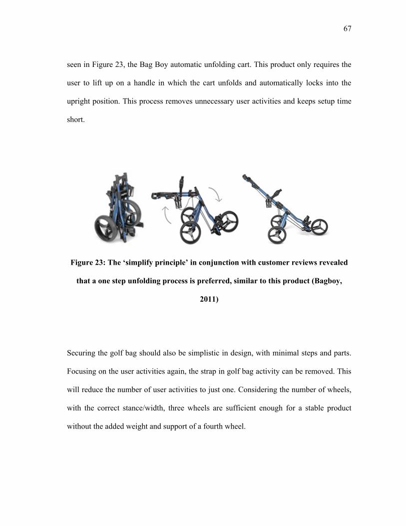
67
seen in Figure 23, the Bag Boy automatic unfolding cart. This product only requires the
user to lift up on a handle in which the cart unfolds and automatically locks into the
upright position. This process removes unnecessary user activities and keeps setup time
short.
Figure 23: The „simplify principle‟ in conjunction with customer reviews revealed
that a one step unfolding process is preferred, similar to this product (Bagboy,
2011)
Securing the golf bag should also be simplistic in design, with minimal steps and parts.
Focusing on the user activities again, the strap in golf bag activity can be removed. This
will reduce the number of user activities to just one. Considering the number of wheels,
with the correct stance/width, three wheels are sufficient enough for a stable product
without the added weight and support of a fourth wheel.
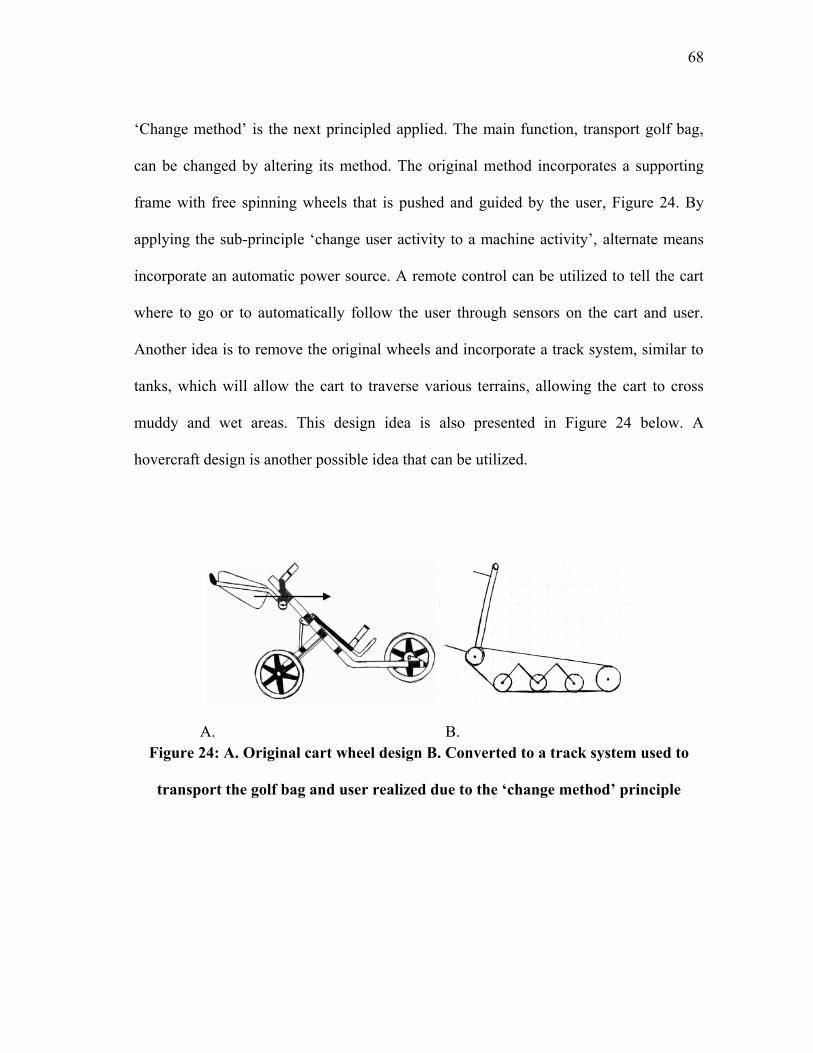
68
„Change method‟ is the next principled applied. The main function, transport golf bag,
can be changed by altering its method. The original method incorporates a supporting
frame with free spinning wheels that is pushed and guided by the user, Figure 24. By
applying the sub-principle „change user activity to a machine activity‟, alternate means
incorporate an automatic power source. A remote control can be utilized to tell the cart
where to go or to automatically follow the user through sensors on the cart and user.
Another idea is to remove the original wheels and incorporate a track system, similar to
tanks, which will allow the cart to traverse various terrains, allowing the cart to cross
muddy and wet areas. This design idea is also presented in Figure 24 below. A
hovercraft design is another possible idea that can be utilized.
A. B.
Figure 24: A. Original cart wheel design B. Converted to a track system used to
transport the golf bag and user realized due to the „change method‟ principle
69
The first sub-function of the manual push cart is to „expand to full-size‟ which is
performed manually by the user by unfolding and locking it into place. This can also be
changed to a machine activity through hydraulic pistons or electric motor. Another idea
is to utilize a shape memory material that „remembers‟ its unfolded shape and when
activated, returns to that shape. This was realized by applying the sub-principle „adapt
existing system‟. Various ideas were then derived for ways to secure the golf bag. Some
ideas include utilizing elastic straps like bungee cords, Velcro, magnetic locks and even
automatic self-tightening straps. Figure 25 depicts an adjustable bracket idea that can
also be utilized to secure the golf bag onto the cart. For folding, the user again must
loosen all knobs and manually fold the cart. Ideas for this sub-function are the same as
the unfolding process previously mentioned. Ideas for the emergency brake include a
foot applied system, hand lever system, or even an automatic setup which is
automatically performed once the cart comes to a complete stop.
Figure 25: The „change method‟ principle also led to possible golf bag securing
ideas such as adjustable brackets that are only adjusted once
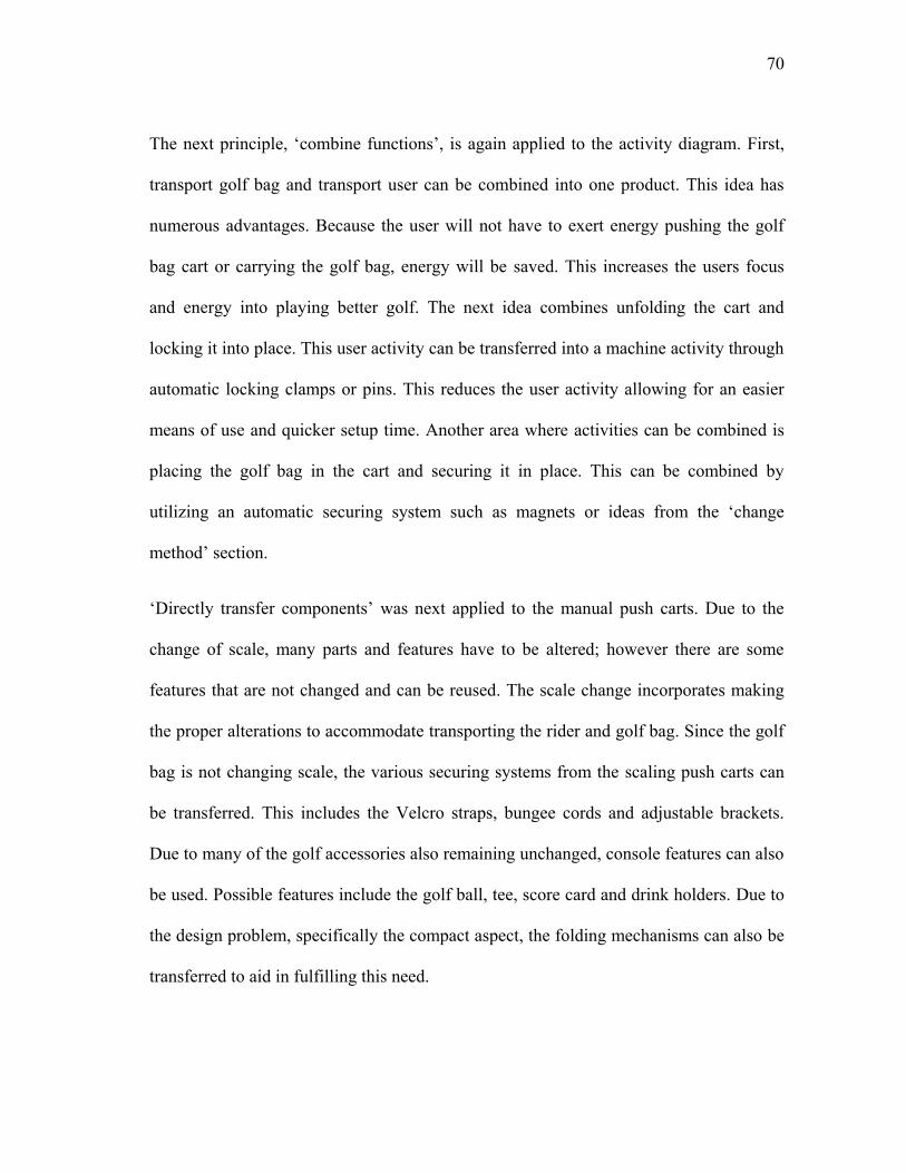
70
The next principle, „combine functions‟, is again applied to the activity diagram. First,
transport golf bag and transport user can be combined into one product. This idea has
numerous advantages. Because the user will not have to exert energy pushing the golf
bag cart or carrying the golf bag, energy will be saved. This increases the users focus
and energy into playing better golf. The next idea combines unfolding the cart and
locking it into place. This user activity can be transferred into a machine activity through
automatic locking clamps or pins. This reduces the user activity allowing for an easier
means of use and quicker setup time. Another area where activities can be combined is
placing the golf bag in the cart and securing it in place. This can be combined by
utilizing an automatic securing system such as magnets or ideas from the „change
method‟ section.
„Directly transfer components‟ was next applied to the manual push carts. Due to the
change of scale, many parts and features have to be altered; however there are some
features that are not changed and can be reused. The scale change incorporates making
the proper alterations to accommodate transporting the rider and golf bag. Since the golf
bag is not changing scale, the various securing systems from the scaling push carts can
be transferred. This includes the Velcro straps, bungee cords and adjustable brackets.
Due to many of the golf accessories also remaining unchanged, console features can also
be used. Possible features include the golf ball, tee, score card and drink holders. Due to
the design problem, specifically the compact aspect, the folding mechanisms can also be
transferred to aid in fulfilling this need.

71
The last principle, „change parameters‟, is an important principle to consider since the
product is altered to now support the weight of the user. This additional force on the
product means changing the extensive properties, materials and dimensions. The current
aluminum frame needs to be changed to a stronger aluminum alloy or lightweight steel
alloy. One possible material is 4130 chromoly steel. It is an alloy steel with a high
strength-to-weight ratio. Besides the frame‟s material, other material changes were taken
into account. An example of this is the possibility of changing plastic pieces to carbon
fiber for its added strength while still remaining lightweight. The wheels and tires is
another place where material changes can be made. The rims also need to be altered for
the increased load but can still remain light due to new available materials.
Parameter change also includes the changes in the physical placement of the components
as well as possible additions. Beginning with the wheels, various configurations are
possible. This includes the possibility of using three or four wheels. For a three wheel
vehicle, there are two possible combinations. The first is having one wheel in front and
two in back while the other is two in front and one in back. These different
configurations can be seen in Figure 26 below.
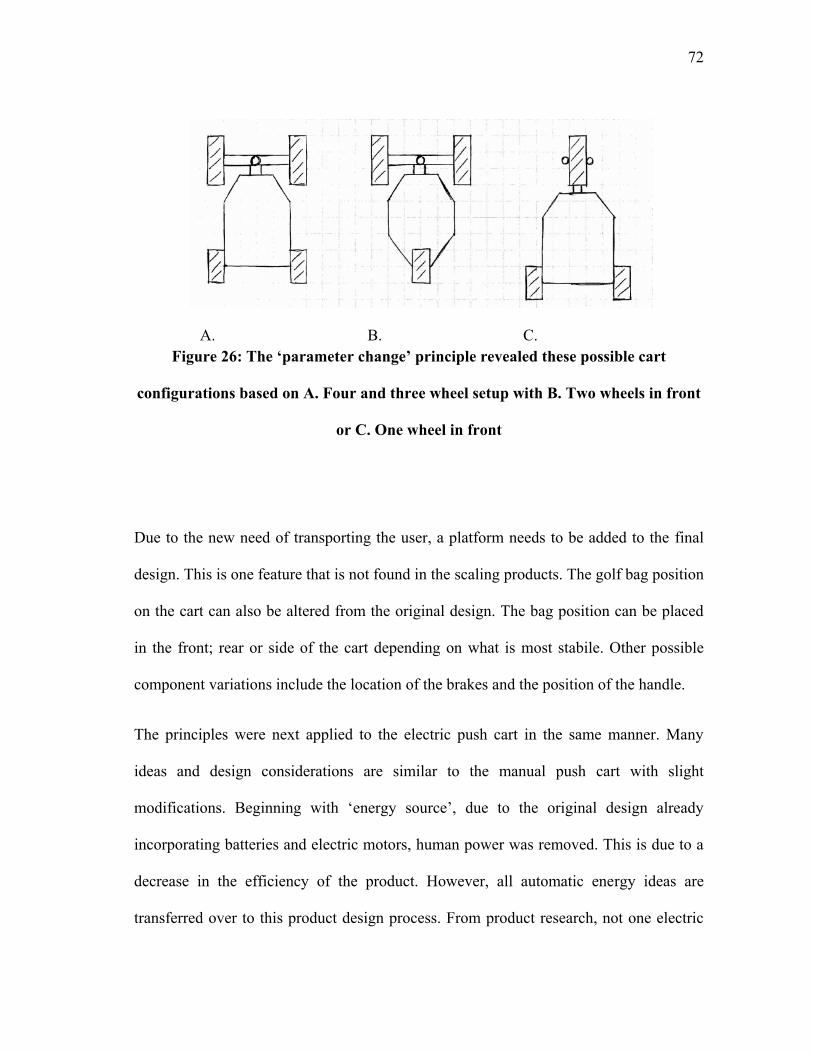
72
A. B. C.
Figure 26: The „parameter change‟ principle revealed these possible cart
configurations based on A. Four and three wheel setup with B. Two wheels in front
or C. One wheel in front
Due to the new need of transporting the user, a platform needs to be added to the final
design. This is one feature that is not found in the scaling products. The golf bag position
on the cart can also be altered from the original design. The bag position can be placed
in the front; rear or side of the cart depending on what is most stabile. Other possible
component variations include the location of the brakes and the position of the handle.
The principles were next applied to the electric push cart in the same manner. Many
ideas and design considerations are similar to the manual push cart with slight
modifications. Beginning with „energy source‟, due to the original design already
incorporating batteries and electric motors, human power was removed. This is due to a
decrease in the efficiency of the product. However, all automatic energy ideas are
transferred over to this product design process. From product research, not one electric
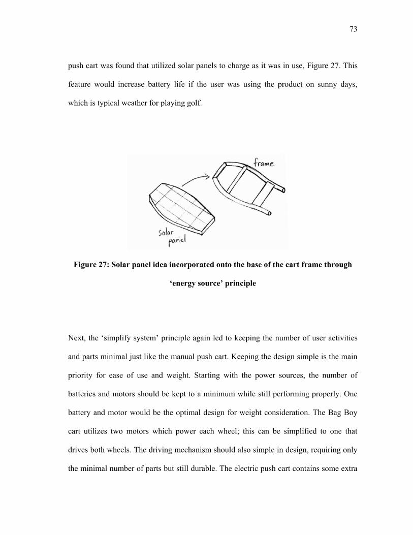
73
push cart was found that utilized solar panels to charge as it was in use, Figure 27. This
feature would increase battery life if the user was using the product on sunny days,
which is typical weather for playing golf.
Figure 27: Solar panel idea incorporated onto the base of the cart frame through
„energy source‟ principle
Next, the „simplify system‟ principle again led to keeping the number of user activities
and parts minimal just like the manual push cart. Keeping the design simple is the main
priority for ease of use and weight. Starting with the power sources, the number of
batteries and motors should be kept to a minimum while still performing properly. One
battery and motor would be the optimal design for weight consideration. The Bag Boy
cart utilizes two motors which power each wheel; this can be simplified to one that
drives both wheels. The driving mechanism should also simple in design, requiring only
the minimal number of parts but still durable. The electric push cart contains some extra
74
accessories that can be removed or simplified. One of these is the remote control with its
additional mechanisms for operation. This feature is considered to be a customer want
not a need. With this removal, several steering mechanisms can be removed, saving
weight.
„Change method‟ ideas are again all transferred over from the manual push cart since
there are many similarities. This includes the minimal step and parts involved with the
unfolding and folding process. It also includes the various ideas for securing the golf bag
onto the cart.
For „combine functions‟, again ideas are shared from the manual push cart. A new idea
with this specific cart involves combing the battery placement in the cart and plug in.
These two steps can be incorporated into one through a battery with prongs that
automatically make the electrical connection. This design would be similar to a cell
phone battery with its metallic prongs, as seen in Figure 28.
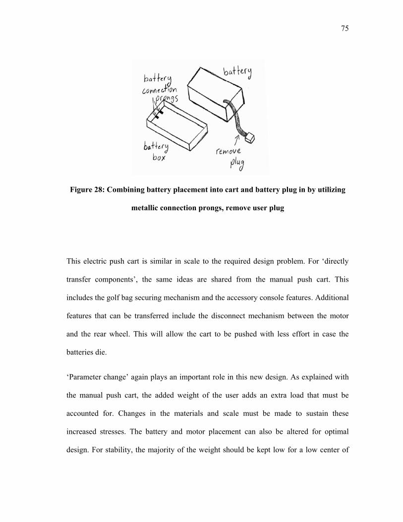
75
Figure 28: Combining battery placement into cart and battery plug in by utilizing
metallic connection prongs, remove user plug
This electric push cart is similar in scale to the required design problem. For „directly
transfer components‟, the same ideas are shared from the manual push cart. This
includes the golf bag securing mechanism and the accessory console features. Additional
features that can be transferred include the disconnect mechanism between the motor
and the rear wheel. This will allow the cart to be pushed with less effort in case the
batteries die.
„Parameter change‟ again plays an important role in this new design. As explained with
the manual push cart, the added weight of the user adds an extra load that must be
accounted for. Changes in the materials and scale must be made to sustain these
increased stresses. The battery and motor placement can also be altered for optimal
design. For stability, the majority of the weight should be kept low for a low center of
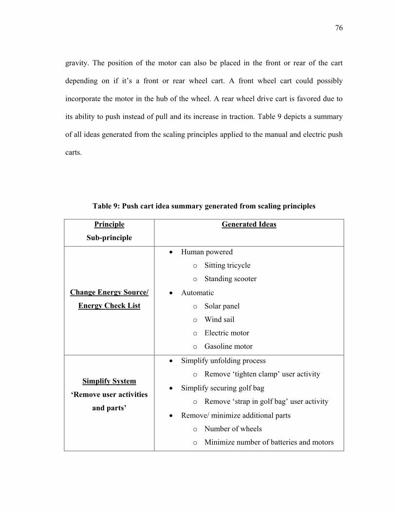
76
gravity. The position of the motor can also be placed in the front or rear of the cart
depending on if it‟s a front or rear wheel cart. A front wheel cart could possibly
incorporate the motor in the hub of the wheel. A rear wheel drive cart is favored due to
its ability to push instead of pull and its increase in traction. Table 9 depicts a summary
of all ideas generated from the scaling principles applied to the manual and electric push
carts.
Table 9: Push cart idea summary generated from scaling principles
Principle
Sub-principle
Generated Ideas
Change Energy Source/
Energy Check List
Human powered
o Sitting tricycle
o Standing scooter
Automatic
o Solar panel
o Wind sail
o Electric motor
o Gasoline motor
Simplify System
„Remove user activities
and parts‟
Simplify unfolding process
o Remove „tighten clamp‟ user activity
Simplify securing golf bag
o Remove „strap in golf bag‟ user activity
Remove/ minimize additional parts
o Number of wheels
o Minimize number of batteries and motors
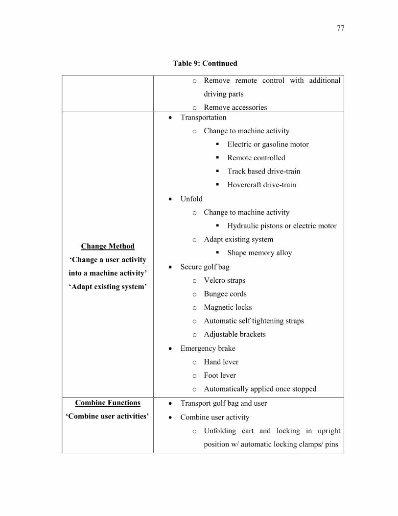
77
Table 9: Continued
o Remove remote control with additional
driving parts
o Remove accessories
Change Method
„Change a user activity
into a machine activity‟
„Adapt existing system‟
Transportation
o Change to machine activity
Electric or gasoline motor
Remote controlled
Track based drive-train
Hovercraft drive-train
Unfold
o Change to machine activity
Hydraulic pistons or electric motor
o Adapt existing system
Shape memory alloy
Secure golf bag
o Velcro straps
o Bungee cords
o Magnetic locks
o Automatic self tightening straps
o Adjustable brackets
Emergency brake
o Hand lever
o Foot lever
o Automatically applied once stopped
Combine Functions
„Combine user activities‟
Transport golf bag and user
Combine user activity
o Unfolding cart and locking in upright
position w/ automatic locking clamps/ pins
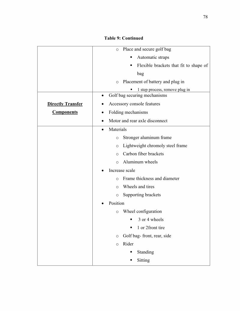
78
Table 9: Continued
o Place and secure golf bag
Automatic straps
Flexible brackets that fit to shape of
bag
o Placement of battery and plug in
1 step process, remove plug in
Directly Transfer
Components
Golf bag securing mechanisms
Accessory console features
Folding mechanisms
Motor and rear axle disconnect
Materials
o Stronger aluminum frame
o Lightweight chromoly steel frame
o Carbon fiber brackets
o Aluminum wheels
Increase scale
o Frame thickness and diameter
o Wheels and tires
o Supporting brackets
Position
o Wheel configuration
3 or 4 wheels
1 or 2front tire
o Golf bag- front, rear, side
o Rider
Standing
Sitting
79
Table 9: Continued
o Handle
Front
Sides
o Brakes
Rear
Front
o Motor
Rear- rear wheel drive
Front- incorporated into wheel hub,
front wheel drive
4.3 Large Scale
The scaling method and principles are next applied to the large scale product, electric
golf cart. The process and generated ideas are described in detail in the following
sections.
4.3.1 The Scaling Method with Large Scale Products
Scaling down from a larger scale was also performed in order to understand both
sides of the product scale. The large scaling product chosen for this problem is an EZGO
TXT electric golf cart ($5000) (EZ GO, 2011), depicted in Figure 29. This is a well-
known and typical golf cart used at golf courses that users rent on a daily basis. An
internet search was performed for customer reviews through Google search by using
„ezgo golf cart review‟ in the search field. Websites such as Golfcartcomparison.com
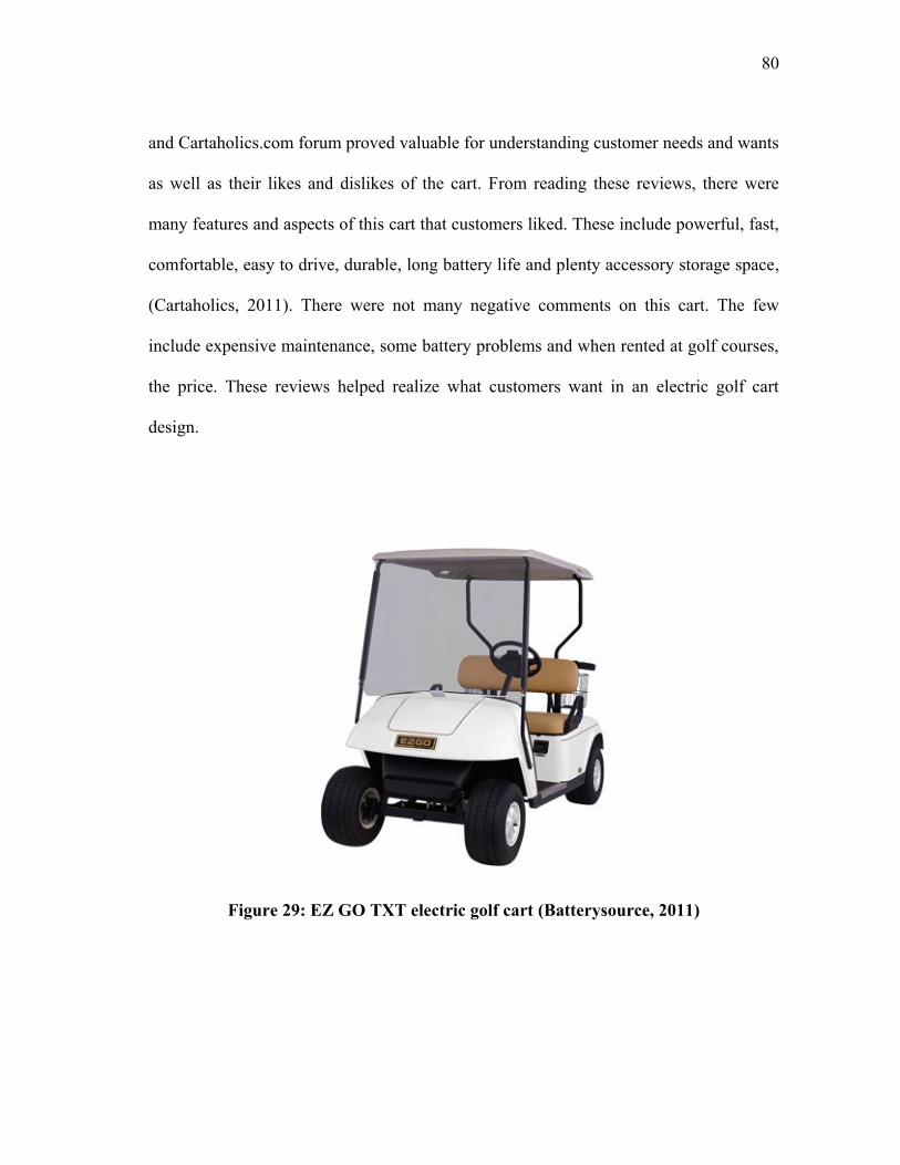
80
and Cartaholics.com forum proved valuable for understanding customer needs and wants
as well as their likes and dislikes of the cart. From reading these reviews, there were
many features and aspects of this cart that customers liked. These include powerful, fast,
comfortable, easy to drive, durable, long battery life and plenty accessory storage space,
(Cartaholics, 2011). There were not many negative comments on this cart. The few
include expensive maintenance, some battery problems and when rented at golf courses,
the price. These reviews helped realize what customers want in an electric golf cart
design.
Figure 29: EZ GO TXT electric golf cart (Batterysource, 2011)
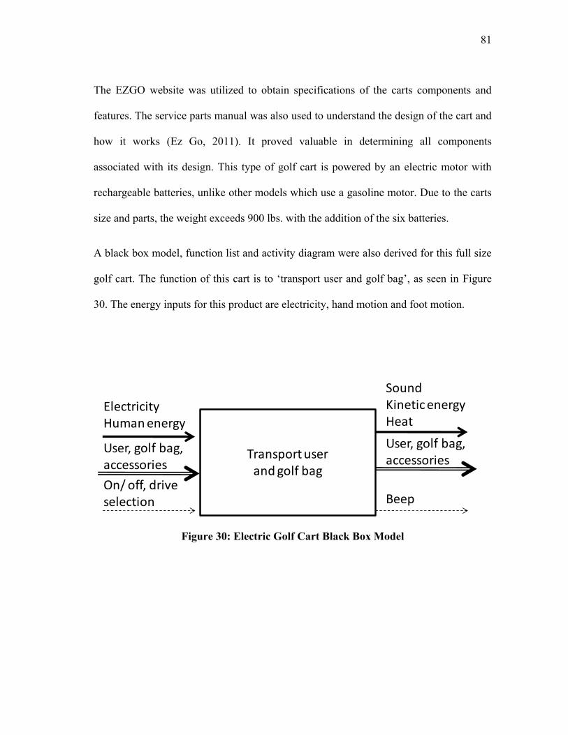
81
The EZGO website was utilized to obtain specifications of the carts components and
features. The service parts manual was also used to understand the design of the cart and
how it works (Ez Go, 2011). It proved valuable in determining all components
associated with its design. This type of golf cart is powered by an electric motor with
rechargeable batteries, unlike other models which use a gasoline motor. Due to the carts
size and parts, the weight exceeds 900 lbs. with the addition of the six batteries.
A black box model, function list and activity diagram were also derived for this full size
golf cart. The function of this cart is to „transport user and golf bag‟, as seen in Figure
30. The energy inputs for this product are electricity, hand motion and foot motion.
Figure 30: Electric Golf Cart Black Box Model
Transport user and golf bag
User, golf bag, accessories
ElectricityHuman energy
On/ off, drive selection
Sound Kinetic energyHeat
Beep
User, golf bag, accessories
82
Next, the sub-functions as well as the user and machine activities are presented for this
electric golf cart below in Table 10. This helps in understanding how the golf cart
functions and sub-functions are performed.
Table 10: Electric golf cart sub-functions
• Load golf bag
o Lift and place golf bag onto cart- user activity
o Strap in golf bag (lever clip)- user activity
• Transport golf bags and passengers around golf course
o Throttle control- user activity
o Cart propulsion- machine activity
o Press and release brake- user activity
• Unload golf bag
o Un-strap golf bag- user activity
o Lift and remove golf bag from cart- user activity
Finally, the activity diagram is presented in Figure 31 in order to understand all possible
tasks performed by the user.
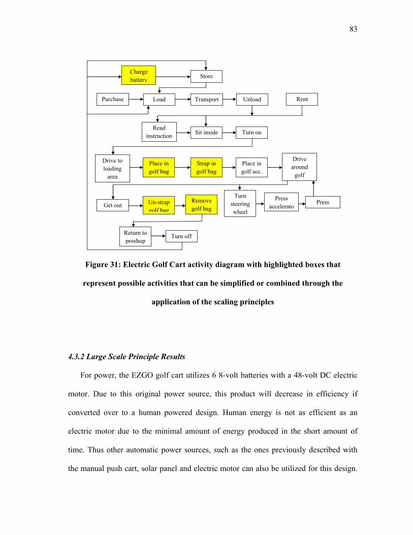
83
Figure 31: Electric Golf Cart activity diagram with highlighted boxes that
represent possible activities that can be simplified or combined through the
application of the scaling principles
4.3.2 Large Scale Principle Results
For power, the EZGO golf cart utilizes 6 8-volt batteries with a 48-volt DC electric
motor. Due to this original power source, this product will decrease in efficiency if
converted over to a human powered design. Human energy is not as efficient as an
electric motor due to the minimal amount of energy produced in the short amount of
time. Thus other automatic power sources, such as the ones previously described with
the manual push cart, solar panel and electric motor can also be utilized for this design.
Purchase Load Transport Unload
Read
instruction
s
Place in
golf bag
Strap in
golf bag
Place in
golf acc.
Remove
golf bag Un-strap
golf bag
Store
Turn on
Rent
Sit inside
Press
accelerato
r
Turn
steering
wheel Get out
Charge
battery
Press
brake
Drive to
loading
area
Turn off
Drive
around
golf
course
Return to
proshop
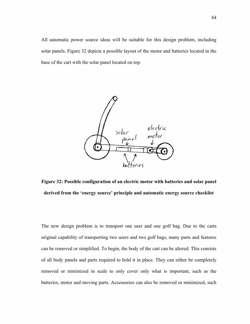
84
All automatic power source ideas will be suitable for this design problem, including
solar panels. Figure 32 depicts a possible layout of the motor and batteries located in the
base of the cart with the solar panel located on top.
Figure 32: Possible configuration of an electric motor with batteries and solar panel
derived from the „energy source‟ principle and automatic energy source checklist
The new design problem is to transport one user and one golf bag. Due to the carts
original capability of transporting two users and two golf bags, many parts and features
can be removed or simplified. To begin, the body of the cart can be altered. This consists
of all body panels and parts required to hold it in place. They can either be completely
removed or minimized in scale to only cover only what is important, such as the
batteries, motor and moving parts. Accessories can also be removed or minimized, such
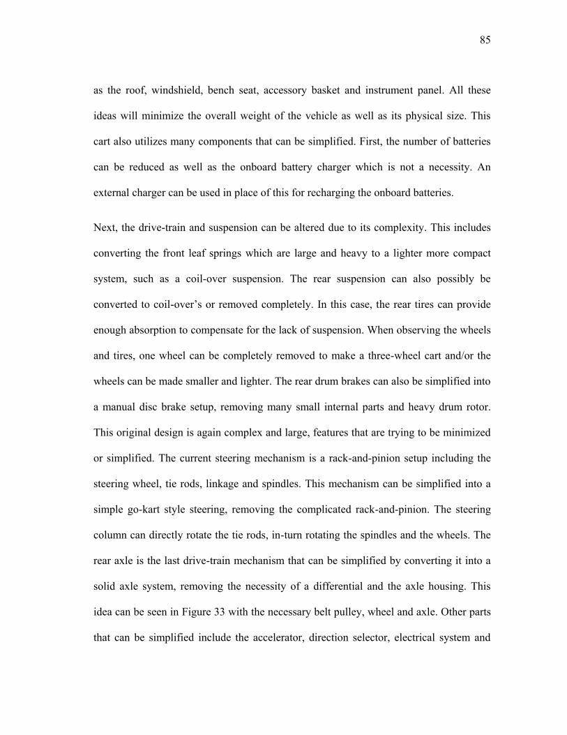
85
as the roof, windshield, bench seat, accessory basket and instrument panel. All these
ideas will minimize the overall weight of the vehicle as well as its physical size. This
cart also utilizes many components that can be simplified. First, the number of batteries
can be reduced as well as the onboard battery charger which is not a necessity. An
external charger can be used in place of this for recharging the onboard batteries.
Next, the drive-train and suspension can be altered due to its complexity. This includes
converting the front leaf springs which are large and heavy to a lighter more compact
system, such as a coil-over suspension. The rear suspension can also possibly be
converted to coil-over‟s or removed completely. In this case, the rear tires can provide
enough absorption to compensate for the lack of suspension. When observing the wheels
and tires, one wheel can be completely removed to make a three-wheel cart and/or the
wheels can be made smaller and lighter. The rear drum brakes can also be simplified into
a manual disc brake setup, removing many small internal parts and heavy drum rotor.
This original design is again complex and large, features that are trying to be minimized
or simplified. The current steering mechanism is a rack-and-pinion setup including the
steering wheel, tie rods, linkage and spindles. This mechanism can be simplified into a
simple go-kart style steering, removing the complicated rack-and-pinion. The steering
column can directly rotate the tie rods, in-turn rotating the spindles and the wheels. The
rear axle is the last drive-train mechanism that can be simplified by converting it into a
solid axle system, removing the necessity of a differential and the axle housing. This
idea can be seen in Figure 33 with the necessary belt pulley, wheel and axle. Other parts
that can be simplified include the accelerator, direction selector, electrical system and
86
the parking brake system. These features and components are again complex, simpler
designs are available to use which better fulfill the design problem.
Figure 33: Original rear housing with axles and differential simplified to a solid
rear axle design with incorporated brake and pulley grasped through the
application of the „simplify system‟ principle (Ezgo, 2011)
The „change method‟ principle is applied to the golf cart functions, sub-functions and its
various mechanisms. Possible ideas for the transport function are similar to the manual
and electric push cart including a track system and magnetic levitation system. As
previously mentioned, the suspension can be converted into a rubber, coil-over or airbag
system with a multitude of suspension geometries and setups. These include
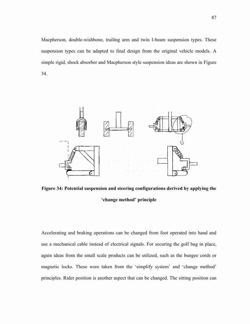
87
Macpherson, double-wishbone, trailing arm and twin I-beam suspension types. These
suspension types can be adapted to final design from the original vehicle models. A
simple rigid, shock absorber and Macpherson style suspension ideas are shown in Figure
34.
Figure 34: Potential suspension and steering configurations derived by applying the
„change method‟ principle
Accelerating and braking operations can be changed from foot operated into hand and
use a mechanical cable instead of electrical signals. For securing the golf bag in place,
again ideas from the small scale products can be utilized, such as the bungee cords or
magnetic locks. These were taken from the „simplify system‟ and „change method‟
principles. Rider position is another aspect that can be changed. The sitting position can
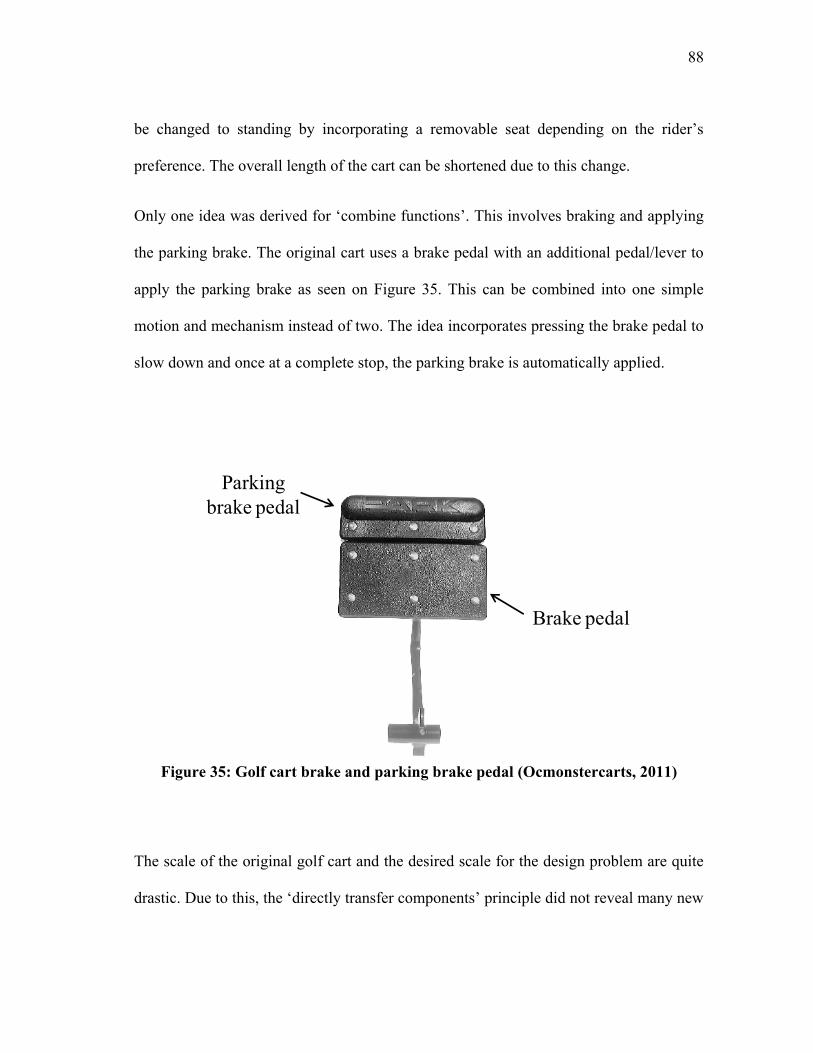
88
be changed to standing by incorporating a removable seat depending on the rider‟s
preference. The overall length of the cart can be shortened due to this change.
Only one idea was derived for „combine functions‟. This involves braking and applying
the parking brake. The original cart uses a brake pedal with an additional pedal/lever to
apply the parking brake as seen on Figure 35. This can be combined into one simple
motion and mechanism instead of two. The idea incorporates pressing the brake pedal to
slow down and once at a complete stop, the parking brake is automatically applied.
Figure 35: Golf cart brake and parking brake pedal (Ocmonstercarts, 2011)
The scale of the original golf cart and the desired scale for the design problem are quite
drastic. Due to this, the „directly transfer components‟ principle did not reveal many new
Brake pedal
Parking
brake pedal
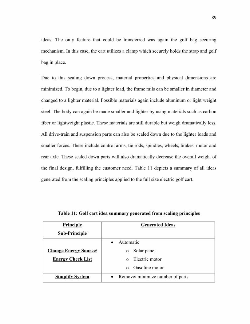
89
ideas. The only feature that could be transferred was again the golf bag securing
mechanism. In this case, the cart utilizes a clamp which securely holds the strap and golf
bag in place.
Due to this scaling down process, material properties and physical dimensions are
minimized. To begin, due to a lighter load, the frame rails can be smaller in diameter and
changed to a lighter material. Possible materials again include aluminum or light weight
steel. The body can again be made smaller and lighter by using materials such as carbon
fiber or lightweight plastic. These materials are still durable but weigh dramatically less.
All drive-train and suspension parts can also be scaled down due to the lighter loads and
smaller forces. These include control arms, tie rods, spindles, wheels, brakes, motor and
rear axle. These scaled down parts will also dramatically decrease the overall weight of
the final design, fulfilling the customer need. Table 11 depicts a summary of all ideas
generated from the scaling principles applied to the full size electric golf cart.
Table 11: Golf cart idea summary generated from scaling principles
Principle
Sub-Principle
Generated Ideas
Change Energy Source/
Energy Check List
Automatic
o Solar panel
o Electric motor
o Gasoline motor
Simplify System Remove/ minimize number of parts
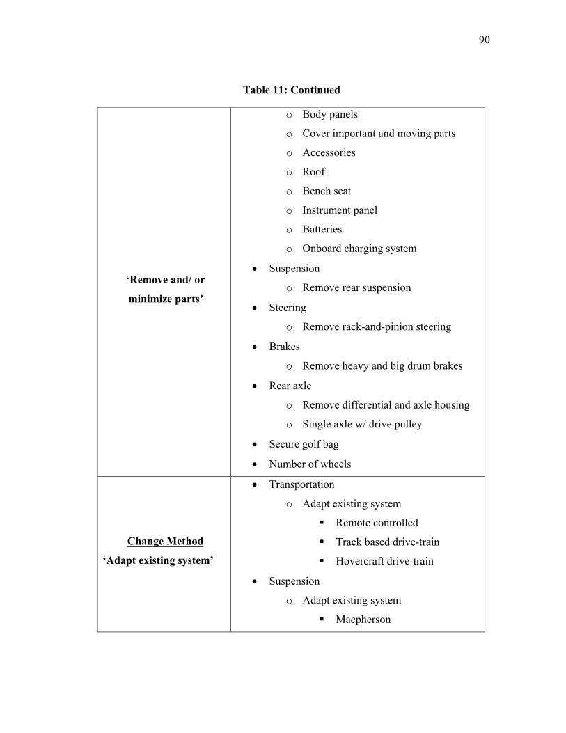
90
Table 11: Continued
„Remove and/ or
minimize parts‟
o Body panels
o Cover important and moving parts
o Accessories
o Roof
o Bench seat
o Instrument panel
o Batteries
o Onboard charging system
Suspension
o Remove rear suspension
Steering
o Remove rack-and-pinion steering
Brakes
o Remove heavy and big drum brakes
Rear axle
o Remove differential and axle housing
o Single axle w/ drive pulley
Secure golf bag
Number of wheels
Change Method
„Adapt existing system‟
Transportation
o Adapt existing system
Remote controlled
Track based drive-train
Hovercraft drive-train
Suspension
o Adapt existing system
Macpherson
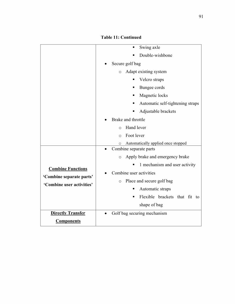
91
Table 11: Continued
Swing axle
Double-wishbone
Secure golf bag
o Adapt existing system
Velcro straps
Bungee cords
Magnetic locks
Automatic self-tightening straps
Adjustable brackets
Brake and throttle
o Hand lever
o Foot lever
o Automatically applied once stopped
Combine Functions
„Combine separate parts‟
„Combine user activities‟
Combine separate parts
o Apply brake and emergency brake
1 mechanism and user activity
Combine user activities
o Place and secure golf bag
Automatic straps
Flexible brackets that fit to
shape of bag
Directly Transfer
Components
Golf bag securing mechanism
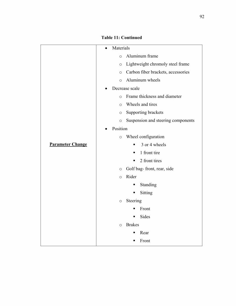
92
Table 11: Continued
Parameter Change
Materials
o Aluminum frame
o Lightweight chromoly steel frame
o Carbon fiber brackets, accessories
o Aluminum wheels
Decrease scale
o Frame thickness and diameter
o Wheels and tires
o Supporting brackets
o Suspension and steering components
Position
o Wheel configuration
3 or 4 wheels
1 front tire
2 front tires
o Golf bag- front, rear, side
o Rider
Standing
Sitting
o Steering
Front
Sides
o Brakes
Rear
Front
93
4.4 Final Concept
With the principles incorporated into the design process and ideas derived, the design
continues with concept selection. The final design incorporates ideas in overall function
and parts derived through applying the scaling principles. These ideas are taken from
both sides of the scaling process, incorporating all ideas and design considerations into
one final concept. First, an electric power source was chosen as the main means of
power due to its advantages. This was chosen due to the customer likes from the electric
push cart and golf cart. It will incorporate two-12 volt rechargeable batteries and a 24-
volt electric motor. A renewable means of energy is also utilized through a solar panel
that will lie on the deck of the cart. This solar panel will be constructed of tempered
glass in order to sustain the weight of the rider. The solar panel will charge the batteries
as the user is playing golf. The batteries, motor and electrical components will all be
contained in the base of the cart. The batteries will remain in the base at all times,
reducing user activities. Besides the solar panel for recharging, the cart will also contain
an external plug to connect the cart to a common 15 amp/ 125 volt power socket.
The base of the cart will be composed of a steel frame with an outer aluminum shell to
protect the internals. The frame will be constructed of 4130 chromoly steel tubing with a
0.75 inch diameter and 0.1 inch thickness. This frame idea was generated from the large
scale golf cart which utilizes frame rails to support the body and components of the cart.
The neck of the frame will contain a hinging point in order for the user to fold the front
wheels and handle onto the base of the cart, reducing its overall area. This folding
mechanism will utilize an automatic locking pin that will activate once in the correct
94
position. When folding, the handle unit will fold down onto the deck where a lock will
hold it in place for ease of transport. These were taken from the unfolding and folding
method ideas of the manual and electric push carts. This keeps the number of user
activities minimal, reducing setup time. Another accessory for the base of the cart is a
slot in which a removable seat can be placed, also derived from the push carts. This seat
will be adjustable in height to suit the user‟s comfort. It incorporates a locking clamp
similar to that found on bicycle seat posts to secure it at the proper rider position.
The overall layout of the cart will be a three-wheel design with two larger wheels in
front and one smaller wheel centered in the rear, as seen in Figure 36. The two front
wheels are 10 inches in diameter while the rear wheel will be 6 inches. The reason why
this configuration was chosen was due to its stability. With two wheels in front, there is
no concern of tipping over when turning. This is common with three wheel vehicles that
utilize one front wheel.
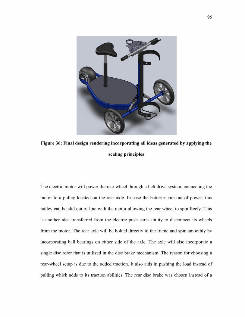
95
Figure 36: Final design rendering incorporating all ideas generated by applying the
scaling principles
The electric motor will power the rear wheel through a belt drive system, connecting the
motor to a pulley located on the rear axle. In case the batteries run out of power, this
pulley can be slid out of line with the motor allowing the rear wheel to spin freely. This
is another idea transferred from the electric push carts ability to disconnect its wheels
from the motor. The rear axle will be bolted directly to the frame and spin smoothly by
incorporating ball bearings on either side of the axle. The axle will also incorporate a
single disc rotor that is utilized in the disc brake mechanism. The reason for choosing a
rear-wheel setup is due to the added traction. It also aids in pushing the load instead of
pulling which adds to its traction abilities. The rear disc brake was chosen instead of a
96
front setup in order to maintain breaking balance. If placed in front of the cart, possible
injuries could occur due to the cart flipping over from sudden stops.
The rear wheel will not contain any type of suspension components. This is due to
keeping the weight of the cart light. The rear tire will be able to absorb small bumps. The
front suspension will absorb the majority of the bumps. A swing axle suspension will be
used which includes control arms, spindles and coilovers. With this type of suspension,
each wheel can move independently of one another adding to the comfort level for the
rider. Each control arm will be able to hinge due to a removable pin located at the upper
mounting point of the coilover. Once disconnected, the coilover and arm can hinge
upward again reducing its overall width. The control arms can then be locked into the
folding position by replacing the pin in the upper mounting position. Figure 37 depicts
the cart once folded at the neck and control arm hinges. The steering mechanism used
will be a simple go-kart style setup. This design incorporates tie rods which are directly
connected to the spindles and lower steering column. As the user rotates the handle, the
steering column also rotates moving the tie rods and the spindles. These suspension and
steering ideas were derived from the large scale golf cart since the push carts do not
utilize steering and suspension. The folding capabilities were derived from the small
scale push carts. It proved valuable in designing a suitable front suspension and steering
system.
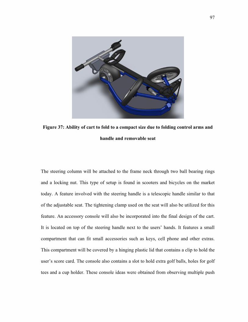
97
Figure 37: Ability of cart to fold to a compact size due to folding control arms and
handle and removable seat
The steering column will be attached to the frame neck through two ball bearing rings
and a locking nut. This type of setup is found in scooters and bicycles on the market
today. A feature involved with the steering handle is a telescopic handle similar to that
of the adjustable seat. The tightening clamp used on the seat will also be utilized for this
feature. An accessory console will also be incorporated into the final design of the cart.
It is located on top of the steering handle next to the users‟ hands. It features a small
compartment that can fit small accessories such as keys, cell phone and other extras.
This compartment will be covered by a hinging plastic lid that contains a clip to hold the
user‟s score card. The console also contains a slot to hold extra golf balls, holes for golf
tees and a cup holder. These console ideas were obtained from observing multiple push
98
carts and choosing features from certain designs. A set of straight handlebars will be
used for the final design. Both sides of the bars will include rubber grips for added
comfort. The right side will also contain a twist throttle control incorporated into the
grip. The left side will support the brake lever which will also incorporate the emergency
brake. This will be activated when the hand brake is fully depressed and deactivate when
pressed again.
The golf bag will be supported by the frame neck and handle in front of the cart. The
reason this placement was chosen was due to the existing column support. No added
brace or structure will need to be added, minimizing weight. The bag will also be
centered in the middle of the cart resulting in proper balance. The golf bag will remain
secured onto the cart through the use of adjustable plastic clamps. These clamps will be
adjusted by the user to fit the diameter of the bag only one time. Once properly adjusted,
the bag will simply slide into place and be securely held. The design was also chosen
from observing push carts and their bag securing mechanisms. All ideas incorporated
from the scaling principles are summarized in Figure 38 below. From the large scale, the
drive-train and all its components were integrated into the final concept design. Small
scale features include all folding and golf bag securing mechanisms as well as
accessories.
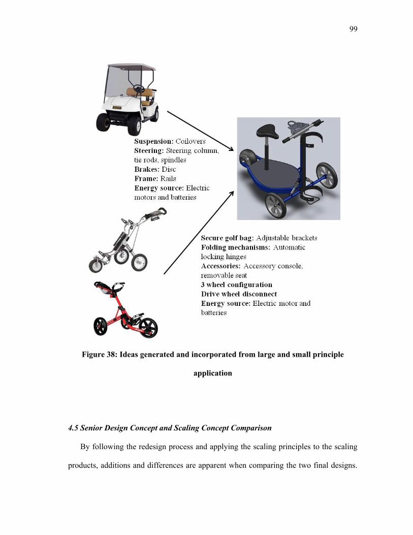
99
Figure 38: Ideas generated and incorporated from large and small principle
application
4.5 Senior Design Concept and Scaling Concept Comparison
By following the redesign process and applying the scaling principles to the scaling
products, additions and differences are apparent when comparing the two final designs.
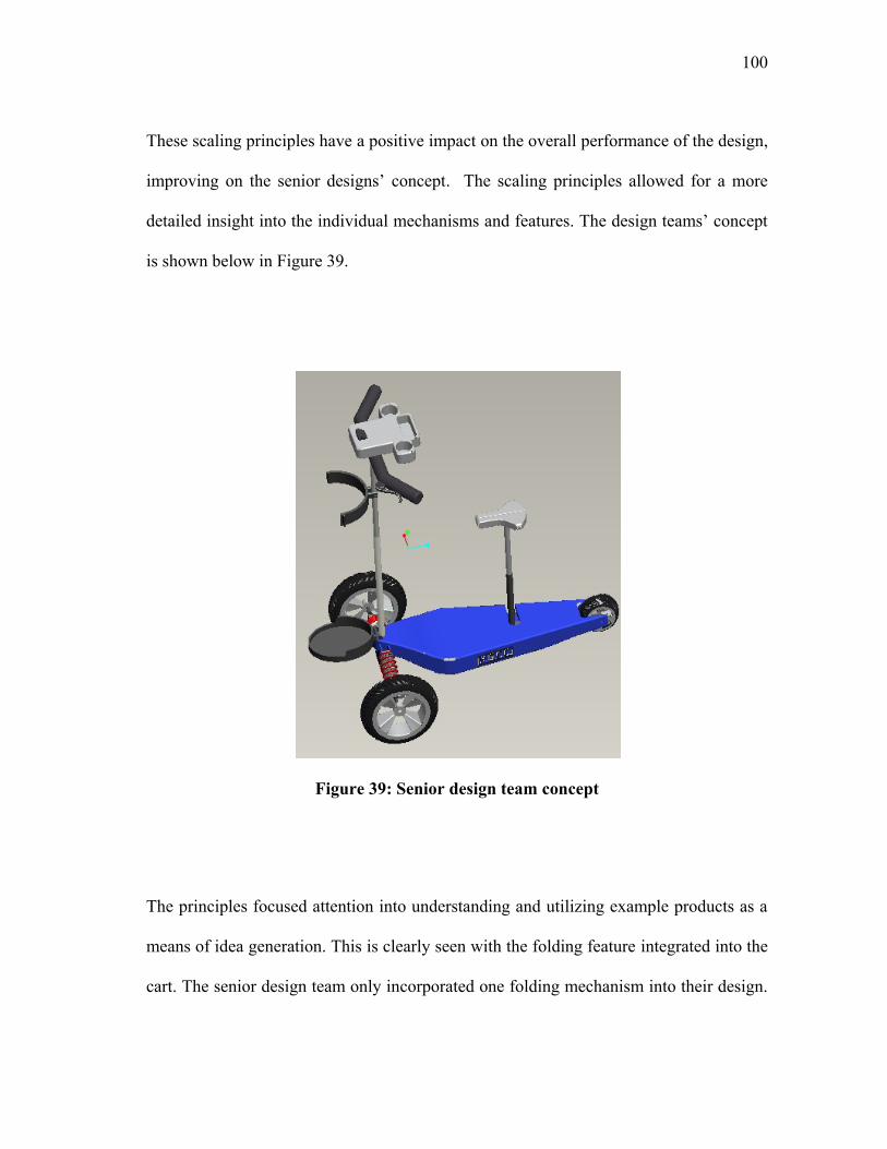
100
These scaling principles have a positive impact on the overall performance of the design,
improving on the senior designs‟ concept. The scaling principles allowed for a more
detailed insight into the individual mechanisms and features. The design teams‟ concept
is shown below in Figure 39.
Figure 39: Senior design team concept
The principles focused attention into understanding and utilizing example products as a
means of idea generation. This is clearly seen with the folding feature integrated into the
cart. The senior design team only incorporated one folding mechanism into their design.
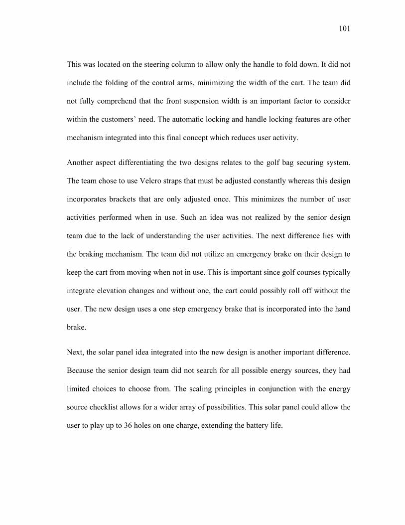
101
This was located on the steering column to allow only the handle to fold down. It did not
include the folding of the control arms, minimizing the width of the cart. The team did
not fully comprehend that the front suspension width is an important factor to consider
within the customers‟ need. The automatic locking and handle locking features are other
mechanism integrated into this final concept which reduces user activity.
Another aspect differentiating the two designs relates to the golf bag securing system.
The team chose to use Velcro straps that must be adjusted constantly whereas this design
incorporates brackets that are only adjusted once. This minimizes the number of user
activities performed when in use. Such an idea was not realized by the senior design
team due to the lack of understanding the user activities. The next difference lies with
the braking mechanism. The team did not utilize an emergency brake on their design to
keep the cart from moving when not in use. This is important since golf courses typically
integrate elevation changes and without one, the cart could possibly roll off without the
user. The new design uses a one step emergency brake that is incorporated into the hand
brake.
Next, the solar panel idea integrated into the new design is another important difference.
Because the senior design team did not search for all possible energy sources, they had
limited choices to choose from. The scaling principles in conjunction with the energy
source checklist allows for a wider array of possibilities. This solar panel could allow the
user to play up to 36 holes on one charge, extending the battery life.

102
The last major difference between the two designs is the ability to disengage the rear
axle from the motor. This idea was obtained from studying the electric push carts.
Several customer reviews stated that they liked this feature since pushing the cart while
still engaged was much more difficult. Without searching these products and reviews,
this important idea would not have been realized. A summary of all differences between
the two designs is depicted in Figure 40.
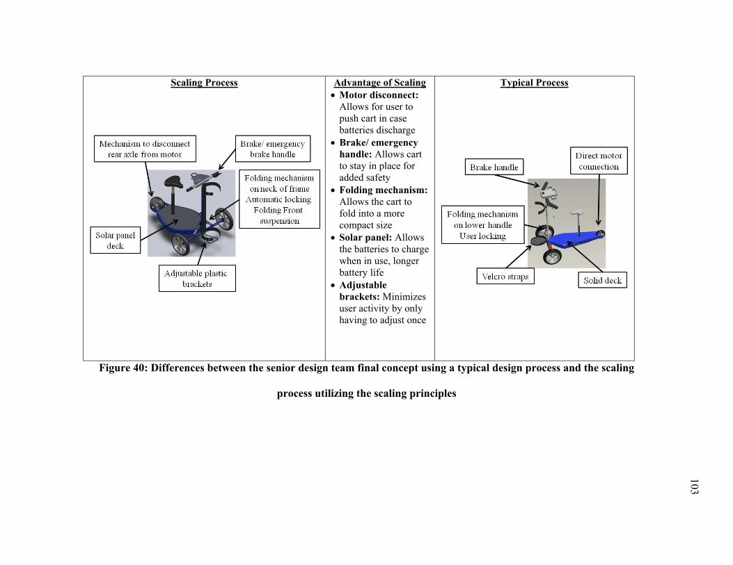
103
Scaling Process
Advantage of Scaling
Motor disconnect:
Allows for user to
push cart in case
batteries discharge
Brake/ emergency
handle: Allows cart
to stay in place for
added safety
Folding mechanism:
Allows the cart to
fold into a more
compact size
Solar panel: Allows
the batteries to charge
when in use, longer
battery life
Adjustable
brackets: Minimizes
user activity by only
having to adjust once
Typical Process
Figure 40: Differences between the senior design team final concept using a typical design process and the scaling
process utilizing the scaling principles
104
Even though the layout of both designs is similar, the scaling method led to additional
ideas that are very beneficial to the overall concept. The scaling principles focus on the
customer needs and ways to accommodate these needs. They are met with higher
standards due to an increase in their consideration. This is done through observing and
studying example products in great detail in order to gain specific as well as broad ideas.
The customer reviews are an additional aid in understanding there likes and dislikes for
specific products. Due to this, small additions are added to the design that has a large
effect on the overall performance. The additional folding feature and the new placement
of the handle hinge help decrease the carts folded dimensions. This compact size will
allow it to fit in smaller vehicles, increasing the market size. The automatic locking pins
also remove user activities to make setup quicker and easier. These changes are an
improvement over the senior design teams‟ concept due to the scaling method and
principles.
105
5. CONCLUSIONS AND FUTURE WORK
Scaling of existing products and natural systems are continuously performed by
engineers and designers. They are altered due to the changing needs and wants of
customers, bioinspiration and design-by-analogy. Normally, engineers utilize a typical
design or redesign process in which example products are reverse engineered. This is
characteristically performed when designing a product that suits the same scale as the
example product. When a product is designed to suit a different product scale, the
redesign process falls short in guiding the designers through the scaling process. There
is no current systematic approach to scaling products to the desired level. This research
utilized an empirical research approach for understanding scaled products in order to
generate a systematic process.
Due to the small amount of example products and/or systems used to derive these
scaling principles, 46, not all possible changes that occur through the scaling process
could be revealed. However, enough information was offered to derive six general
scaling principles that form a bases on which ideas can be generated for product scaling.
These principles include: „change energy source‟, „simplify system‟, „change method‟,
„combine functions‟, „directly transfer components‟ and „parameter change‟. They all
work together to break down the scaling product to its most basic foundations in order to
generate novel and robust ideas. In conjunction with the change energy source principle,
human and automatic energy checklists were derived. They proved valuable in
understanding various combinations of power sources that can be implemented into a
106
design. Depending on the design constraints and customer needs, the most fitting power
source or combination of can be chosen from these checklists.
In order for these principles to be properly applied to the design problem and generate
the most ideas, a scaling process is required. These steps and tasks include determining
the scaling products‟ main function, sub-functions, user and machine activities, detailed
mechanisms, parts and how they work in conjunction with one another. Customer
analysis is another important step, which involves researching and gathering information
on customer needs, wants, likes and dislikes. This contributes to appealing to the
customer and in turn, develops a well-designed product that fulfills the preferred market
scale. This scaling method in combination with the principles can be used to make the
product development process more efficient as well as improve on the original design.
The comparative case study implemented in this research validated the process and
principles as a possible idea generation method for product scaling. By taking on a
previously solved design problem, designing a portable golf transportation system to
transport the user and golf bag, the final concepts were compared to reveal the affects of
the scaling principles on the final design. By using the scaling process in conjunction
with the principles, there was greater insight into the products‟ individual functions and
components. The principles require the scaling products to be broken down to their most
basic functions in order to take full advantage of. This allows for more ideas to be
generated for specific functions and sub-functions which in turn generated a better
performing solution.
107
Even though the case study showed that ideas could be generated through the application
of the scaling principles, there are some conclusions that cannot be made. First, it does
not prove that they will work on a design problem which requires a large scale change.
An example of this is scaling the original product or system at a macro scale to a nano
scale. Secondly, the case study does not establish the principles as a biomimetic idea
generation method. The design problem consisted of redesigning and scaling a market
product, not a natural system. This can be solved by undertaking another case study
which incorporates a biomimetic design problem. This can possibly show that these
scaling principles can also work for bioinspiration.
The final concept incorporated features and ideas generated from both sides of the
product scale. By scaling from two sides, a full understanding of important features was
realized that are necessary to incorporate into the design. From the small scale products,
compact features were the most important aspects considered. This includes all folding
and locking mechanisms, golf bag securing mechanisms and user accessories. These
small features appeal to the user and their activities, which are minimal in scale but
make a big difference to the overall design. These features would not have been realized
without the customer analysis including the customer reviews. From the large product
scale, the entire drive-train portion of the design was comprehended. Due to the small
scale products not containing much on this characteristic, another scale needed to be
studied, the large scale product. From here, ideas were generated regarding possible
motor, steering, suspension and frame configurations. This drive-train is important due
to the fact that it must carry and propel both the golf bag and user throughout the golf
108
course safely and consistently. The final design must fulfill the customer needs and
design constraints which are what was accomplished through utilizing the scaling
method and principles.
For this case study, extra input was also gathered on customer likes and dislikes which
could have had an effect on the outcome of the final design when compared to the senior
design concept. This was due to the redesign process and its utilization of determining
customer likes and dislikes for the example product. The senior design teams‟ customer
needs, likes and dislikes were based on their surveys. Even though this data was utilized
for this study, the additional information could have altered the overall design process.
Additional differences between the senior design team and this study include the amount
of time spent on the design problem. First, the senior design team consisted of 3 students
who evenly separated the design tasks. Next, two semesters were devoted to the design
problem. The first semester incorporated project selection, market/ literature search,
design methodology, concept designs and necessary analysis. The second semester
continued with additional idea generation through the building of the physical prototype.
In this study, only the author performed the necessary tasks required to solve the design
problem. The amount of time spent on the design problem in this study was only 3
months. These various differences also have an effect on the final designs developed.
For future work on this scaling process and method, some recommendations are
proposed from insights gained from this thesis. The background research, results and
case study led to the following recommendations:
109
• Test the scaling process and principles: In order to increase the validation of this
scaling process and principles as a viable idea generation method, an experiment can be
implemented on a sample group of students. The experiment will include a problem
statement, similar to this case study, on which to build from. One possible experiment
can test the differences in ideas generated between a typical design process and the
scaling process with its scaling principles. First, the group will go through the typical
design process and steps in order to generate as many ideas possible in a given amount
of time. Next, the group will follow the scaling process and generate as many ideas as
possible in that same amount of time. The number of ideas generated from the two
processes can then be compared to see if the scaling process aided in determining more
ideas. Another possible experiment is testing whether scaling from two product scales is
better than scaling from just one. The experiment will consist of two groups which both
have all necessary information and steps provided to them. The first group will follow
the scaling process and generate as many ideas possible from applying the principles to
only one scale, small. The second group will be given additional information on the
other scale on which they can apply to both scales to generate as many ideas as possible.
Once completed, the number of generated ideas can be compared to determine whether
scaling from two scales is better than one. All information gathered will be analyzed to
determine the effectiveness of this process and principles.
• Study and research a greater number of example products: The amount of example
products researched for determining these scaling principles can be increased in order to
view a broader range of items. This increase in products might uncover additional
110
insights into product differences throughout the product scale. This can include
increasing the number of product categories as well as product scales within each
category. Increasing the number of product categories widens the amount of products
studied and the ability to view additional mechanisms and features not covered within
this thesis. The number of product scales within each product category can also be
increased to view additional differences. In this thesis, the number of product scales for
each category was two or three; this included small, medium and large. This number can
be increased to five or six which will give a more detailed view into the more subtle
changes made when the scale change is not very dramatic. This will allow for more
detailed sub-principles to be derived.
• Compare to additional idea generation methods: To test its effectiveness as an idea
generation method, an experiment can be made to compare it to other common methods.
This experiment will consist of comparing the number of ideas generated from utilizing
one method, say TIPS/TRIZ, to the scaling method. It will again entail a design problem
and all necessary information required to properly apply both methods. The group will
first generate ideas using the TIPS/TRIZ method in a given amount of time. Then using
the scaling method, generate as many ideas in the same amount of time. The results can
then be compared to determine whether the scaling method derived more ideas. This can
also be compared to other idea generation methods, such as the Wordtree method and 6-
3-5.
111
• Apply to another case study: This process and principles were only applied to one case
study in which ideas were generated and problem solved. It was then compared to a
previous design which was undertaken and solved at an earlier date to view the
differences between the final concepts. The results showed that by utilizing the scaling
principles, a more detailed understanding of the product and its features was realized.
Another case study can be undertaken to determine whether the same results are derived.
It can entail applying the scaling method and principles to another previously solved
design problem to view their differences. The comparison between the results of the two
case studies can show how the principles affect the idea generation process. Additional
case studies can also be performed on various product categories and scales. This will
prove that the principles work on all product scales and categories, not just this one.
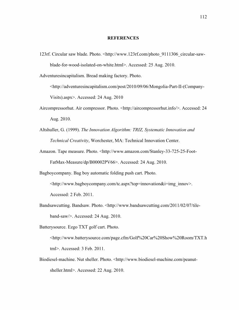
112
REFERENCES
123rf. Circular saw blade. Photo. <http://www.123rf.com/photo_9111306_circular-saw-
blade-for-wood-isolated-on-white.html>. Accessed: 25 Aug. 2010.
Adventuresincapitalism. Bread making factory. Photo.
<http://adventuresincapitalism.com/post/2010/09/06/Mongolia-Part-II-(Company-
Visits).aspx>. Accessed: 24 Aug. 2010
Aircompressorhut. Air compressor. Photo. <http://aircompressorhut.info/>. Accessed: 24
Aug. 2010.
Altshuller, G. (1999). The Innovation Algorithm: TRIZ, Systematic Innovation and
Technical Creativity, Worchester, MA: Technical Innovation Center.
Amazon. Tape measure. Photo. <http://www.amazon.com/Stanley-33-725-25-Foot-
FatMax-Measure/dp/B00002PV66>. Accessed: 24 Aug. 2010.
Bagboycompany. Bag boy automatic folding push cart. Photo.
<http://www.bagboycompany.com/tc.aspx?top=innovation&i=img_innov>.
Accessed: 2 Feb. 2011.
Bandsawcutting. Bandsaw. Photo. <http://www.bandsawcutting.com/2011/02/07/tile-
band-saw/>. Accessed: 24 Aug. 2010.
Batterysource. Ezgo TXT golf cart. Photo.
<http://www.batterysource.com/page.cfm/Golf%20Car%20Show%20Room/TXT.h
tml>. Accessed: 3 Feb. 2011.
Biodiesel-machine. Nut sheller. Photo. <http://www.biodiesel-machine.com/peanut-
sheller.html>. Accessed: 22 Aug. 2010.
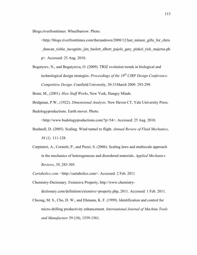
113
Blogs.riverfronttimes. Wheelbarrow. Photo.
<http://blogs.riverfronttimes.com/therundown/2008/12/last_minute_gifts_for_chris
_duncan_richie_incognito_jim_haslett_albert_pujols_gary_pinkel_rick_majerus.ph
p>. Accessed: 25 Aug. 2010.
Bogatyrev, N., and Bogatyreva, O. (2009). TRIZ evolution trends in biological and
technological design strategies. Proceedings of the 19th
CIRP Design Conference-
Competitive Design. Cranfield University, 30-31March 2009. 293-299.
Brain, M., (2001). How Stuff Works, New York, Hungry Minds.
Bridgman, P.W., (1922). Dimensional Analysis. New Haven CT, Yale University Press.
Budologyproductions. Earth mover. Photo.
<http://www.budologyproductions.com/?p=54>. Accessed: 25 Aug. 2010.
Bushnell, D. (2005). Scaling: Wind tunnel to flight. Annual Review of Fluid Mechanics,
38 (1), 111-128.
Carpinteri, A., Cornetti, P., and Puzzi, S. (2006). Scaling laws and multiscale approach
in the mechanics of heterogeneous and disordered materials. Applied Mechanics
Reviews, 59, 283-305.
Cartaholics.com. <http://cartaholics.com>. Accessed: 2 Feb. 2011
Chemistry-Dictionary. Extensive Property, http://www.chemistry-
dictionary.com/definition/extensive+property.php, 2011. Accessed: 1 Feb. 2011.
Cheong, M. S., Cho, D. W., and Ehmann, K. F. (1999). Identification and control for
micro-drilling productivity enhancement. International Journal of Machine Tools
and Manufacture 39 (10), 1539-1561.
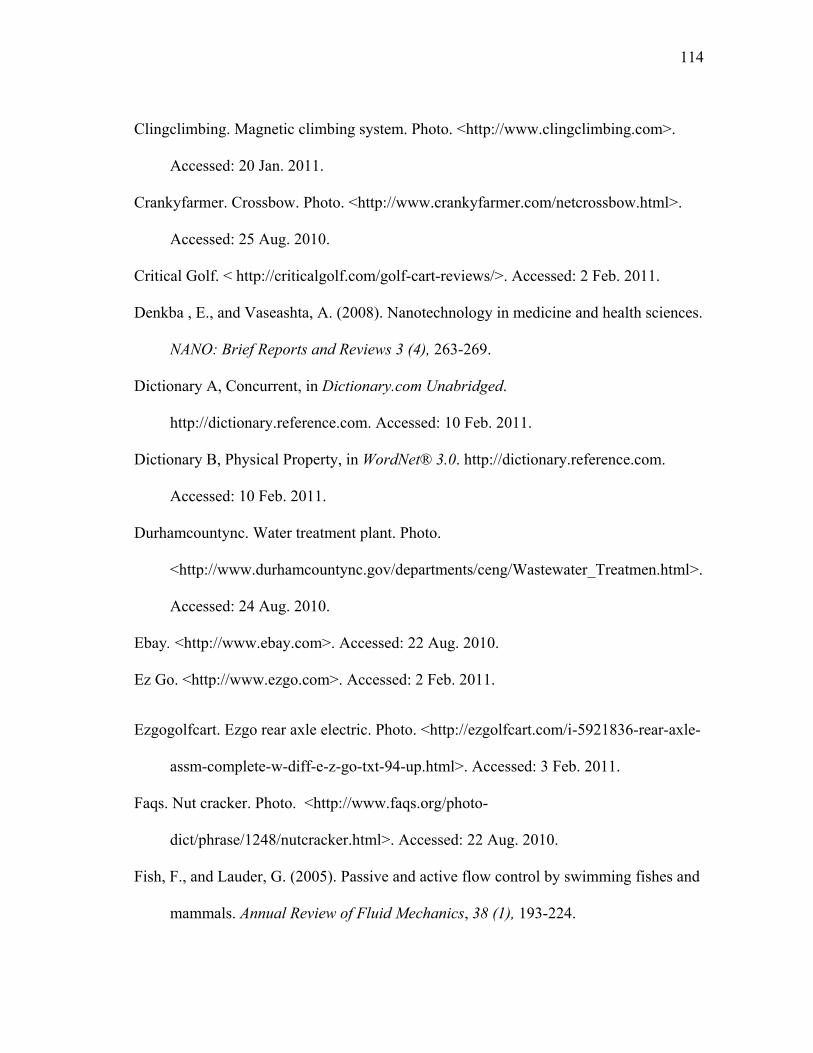
114
Clingclimbing. Magnetic climbing system. Photo. <http://www.clingclimbing.com>.
Accessed: 20 Jan. 2011.
Crankyfarmer. Crossbow. Photo. <http://www.crankyfarmer.com/netcrossbow.html>.
Accessed: 25 Aug. 2010.
Critical Golf. < http://criticalgolf.com/golf-cart-reviews/>. Accessed: 2 Feb. 2011.
Denkba , E., and Vaseashta, A. (2008). Nanotechnology in medicine and health sciences.
NANO: Brief Reports and Reviews 3 (4), 263-269.
Dictionary A, Concurrent, in Dictionary.com Unabridged.
http://dictionary.reference.com. Accessed: 10 Feb. 2011.
Dictionary B, Physical Property, in WordNet® 3.0. http://dictionary.reference.com.
Accessed: 10 Feb. 2011.
Durhamcountync. Water treatment plant. Photo.
<http://www.durhamcountync.gov/departments/ceng/Wastewater_Treatmen.html>.
Accessed: 24 Aug. 2010.
Ebay. <http://www.ebay.com>. Accessed: 22 Aug. 2010.
Ez Go. <http://www.ezgo.com>. Accessed: 2 Feb. 2011.
Ezgogolfcart. Ezgo rear axle electric. Photo. <http://ezgolfcart.com/i-5921836-rear-axle-
assm-complete-w-diff-e-z-go-txt-94-up.html>. Accessed: 3 Feb. 2011.
Faqs. Nut cracker. Photo. <http://www.faqs.org/photo-
dict/phrase/1248/nutcracker.html>. Accessed: 22 Aug. 2010.
Fish, F., and Lauder, G. (2005). Passive and active flow control by swimming fishes and
mammals. Annual Review of Fluid Mechanics, 38 (1), 193-224.
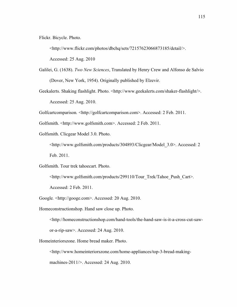
115
Flickr. Bicycle. Photo.
<http://www.flickr.com/photos/dbchq/sets/72157623066873185/detail/>.
Accessed: 25 Aug. 2010
Galilei, G. (1638). Two New Sciences, Translated by Henry Crew and Alfonso de Salvio
(Dover, New York, 1954). Originally published by Elzevir.
Geekalerts. Shaking flashlight. Photo. <http://www.geekalerts.com/shaker-flashlight/>.
Accessed: 25 Aug. 2010.
Golfcartcomparison. <http://golfcartcomparison.com>. Accessed: 2 Feb. 2011.
Golfsmith. <http://www.golfsmith.com>. Accessed: 2 Feb. 2011.
Golfsmith. Clicgear Model 3.0. Photo.
<http://www.golfsmith.com/products/304893/Clicgear/Model_3.0>. Accessed: 2
Feb. 2011.
Golfsmith. Tour trek tahoecart. Photo.
<http://www.golfsmith.com/products/299110/Tour_Trek/Tahoe_Push_Cart>.
Accessed: 2 Feb. 2011.
Google. <http://googe.com>. Accessed: 20 Aug. 2010.
Homeconstructionshop. Hand saw close up. Photo.
<http://homeconstructionshop.com/hand-tools/the-hand-saw-is-it-a-cross-cut-saw-
or-a-rip-saw>. Accessed: 24 Aug. 2010.
Homeinteriorszone. Home bread maker. Photo.
<http://www.homeinteriorszone.com/home-appliances/top-3-bread-making-
machines-2011/>. Accessed: 24 Aug. 2010.
116
Howstuffworks. <http://www.howstuffworks.com>. Accessed: 26 Aug. 2010.
Hsu, T.-R. (2002). Miniaturization- A Paradigm Shift in Advanced Manufacturing and
Education. IEEE/ASME International Conference on Advanced Manufacturing
Technologies and Education in the 21st Century. Chia-Yi, Taiwan, Republic of
China. 10-15 August 2002.
Institute, T. B. (2008). What Is Biomimicry?,
http://asknature.org/article/view/what_is_biomimicry. Accessed: 1/21/2011.
Ipsen, D.C. (1960). Units, Dimensions, and Dimensionless Numbers. New York,
McGraw-Hill Book Company, Inc.
Jiao, J., Simpson, T. W., and Siddique, Z. (2007). Product family design and platform-
based product development: A state-of-the-art review. Journal of Intelligent
Manufacturing, 18 (1), pp. 5-29.
Korchagin, O., Novikov, V., Rakov, E., Kuznetsov, V., and Tarasevich, M. (2009).
Carbon nanotubes as efficient catalyst supports for fuel cells with direct ethanol
oxidation, Russian Journal of Electrochemistry 46 (8), 882-889.
Langhaar, Henry L. (1951). Dimensional Analysis and Theory of Models. New York,
John Wiley & Sons, Inc.
Leemfgco. Electric nut cracker. Photo.
<http://www.leemfgco.com/store/index.php?act=viewProd&productId=7>.
Accessed: 22 Aug. 2010.
Legacy.lclark. Gecko foot close up. Photo. <http://legacy.lclark.edu/>. Accessed: 15 Jan.
2011.
117
Library Tamu. <http://www.library.tamu.edu>. Accessed: 26 Aug. 2010.
Linsey, J.S. (2007). Design-By-Analogy and Representation in Innovative Engineering
Concept Generation. Ph. D. The University of Texas at Austin.
Lohmann, A. (1989). Scaling laws for lens systems. Applied Optics, pp. 28 (23), 4996-
4998.
Macaulay, D., Ardley, N., and Leonard, S. (1998). The New Way Things Work, Boston:
Houghton Mifflin.
Malleast. Sun mountain micro cart. Photo. <http://www.malleast.com/new-2009-sun-
mountain-micro-cart-golf-trolley-silver-p-1819.html>. Accessed: 2 Feb. 2011.
Martin, M. V., and Ishii, K. (2002). Design for variety: Developing standardized and
modularized product platform architectures. Research in engineering Design 13
(4), 213-235.
Meyer, M. H., and Utterback, J. M. (1992). The Product Family and the Dynamics of
Core Capability. International Center for Research on the Management of
Technology, Sloan School of Management, Massachusetts Institute of Technology.
Nosonovsky, M. and Bhushan, B. (2005). Roughness optimization for biomimetic
superhydrophobic surfaces. Microsystem Technologies 11 (7), 535-549.
Ocmonstercarts. Golf cart brake/ parking brake pedal. Photo.
<http://ocmonstercarts.com/cart/products/41/index.php>. Accessed: 5 Feb. 2011.
Openlearn.open A. Goose grass hooks close up. Photo.
<http://openlearn.open.ac.uk/mod/oucontent/view.php?id=397861§ion=1.11.5
>. Accessed: 20 Jan. 2011.
118
Openlearn.open B. Velcro close up. Photo.
<http://openlearn.open.ac.uk/mod/oucontent/view.php?id=397861§ion=1.11.5
>. Accessed: 20 Jan. 2011.
Oshiro, R.E. and Alves, M. (2009). Scaling of structures subject to impact loads when
using a power law constitutive equation. International Journal of Solids and
Structures, 46, 3412-3421.
Otto, K., Wood, K. (2001). Product Design Techniques in Reverse Engineering and New
Product Development. Upper Saddle River, NJ, Prentice Hall.
Pack, R. T., Christopher Jr, J. L., and Kawamura, K. (1997). A rubbertuator-based
structure-climbing inspection robot, Proceedings of the 1997 IEEE Conference on
Robotics and Automation,Albuquerque, NM., 1869-1874.
Paula, G. (1997). Reinventing a core product line. Mechanical Engineering 119 (10),
102-103.
Peterson, H. (1984). Scaling laws applied to wind turbine design. Wind Engineering 8
(2), 99-108.
Peterson, M. (2002). Galileo‟s discovery of scaling laws. American Journal of Physics
70, 575-580.
Pugno, N. (2008). Spiderman gloves. Nano Today 3 (5-6), 35-41.
Rei. Water filter bag. Photo. <http://www.rei.com/product/778043/sawyer-water-filter-
system-4-liter>. Accessed: 24 Aug. 2010.
119
Ren, L., Han, Z., Li, J., and Tong, J. (2002). Effects of non-smooth characteristics on
bionic bulldozer blades in resistance reduction against soil. Journal of
Terramechanics, 39 (4), pp. 221-230.
Reviewsalert. Coleman air pump. Photo. <http://reviewsalert.com/coleman-air-pump-
large-dual-action-hand/>. Accessed: 24 Aug. 2010.
Samsomcnc. Plasma cutter cnc. Photo. <http://www.samsoncnc.com/art.php>. Accessed:
24 Aug. 2010.
Sand Trap, The. < http://thesandtrap.com/b/reviews>. Accessed: 2 Feb. 2011.
Sand Trap, The. Bag boy navigator electric cart. Photo.
<http://thesandtrap.com/b/accessories/page/2>. Accessed: 2 Feb. 2011
Sand Trap, The. Sun mountain speed E cart. Photo.
<http://thesandtrap.com/b/accessories/sun_mountain_speed_e_cart_review>.
Accessed: 2 Feb. 2011.
Sanderson, S., and Uzumeri, M. (1995). Managing product families: The case of the
sony walkman. Research Policy 24 (5), 761-782.
Saunders, M. N., Seepersad, C. C., and Hölttä-Otto, K. (2009). The characteristics of
innovative, mechanical products. Proceedings of the ASME 2009 International
Design Engineering Technical Conferences & Computers and Information in
Engineering Conference, 30 August – 2 September, San Diego, CA.
ScientificAmerican. Gecko foot. Photo.
<http://www.scientificamerican.com/media/inline/>. Accessed: 15 Jan. 2011
120
Simpson, T., Siddique, Z., and Jiao, J. (2006). Platform-based product family
development. Product Platform and Product Family Design: Methods and
Applications. pp. 1–15. New York: Springer.
Simpson, T. W., Maier, J. R. A., and Mistree, F. (2001). Product platform design:
Method and application. Research in Engineering Design 13 (1), pp. 2-22.
Singh, A., Yoon, E.S., Jackson, R. (2009). Biomimetics: The science of imitating nature.
Tribology & Lubrication Technology 65 (2), 40-47.
Singh, V., Skiles, S. M., Krager, J. E., Wood, K. L., Jensen, D., and Sierakowski, R.
(2009). Innovations in design through transformation: A fundamental study of
transformation principles. Journal of Mechanical Design (131), 081010-1 –
081010-18.
Triantafyllou, M., Hover, F., Techet, A., and Yue, D. (2005). Review of hydrodynamic
scaling laws in aquatic locomotion and fishlike swimming. Applied Mechanics
Reviews 58, 226-237.
Vakili, V., and Shu, L. (2001). Towards Biomimetic Concept Generation. Proceedings
of ASME 2001 Design Engineering Technical Conference. Pittsburgh, PA, 9-12
Sept., DETC2001/DTM-21715.
Wautelet, M. (2001). Scaling laws in the macro-, micro-and nanoworlds. European
Journal of Physics 22, pp. 601.
Williamcameronwoodworking. Laser tape. Photo.
<http://www.williamcameronwoodworking.com/Tools/tape_measures.htm>.
Accessed: 24 Aug. 2010.

121
Yamanouchi, T. (1989). Breakthrough: The development of the canon personal copier.
Long Range Planning 22 (5), 11-21.
Zacharias, N. A., and Yassine, A. A. (2008). Optimal platform investment for product
family design. Journal of Intelligent Manufacturing 19 (2), 131-148.
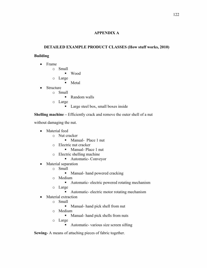
122
APPENDIX A
DETAILED EXAMPLE PRODUCT CLASSES (How stuff works, 2010)
Building
Frame
o Small
Wood
o Large
Metal
Structure
o Small
Random walls
o Large
Large steel box, small boxes inside
Shelling machine – Efficiently crack and remove the outer shell of a nut
without damaging the nut.
Material feed
o Nut cracker
Manual- Place 1 nut
o Electric nut cracker
Manual- Place 1 nut
o Electric shelling machine
Automatic- Conveyor
Material separation
o Small
Manual- hand powered cracking
o Medium
Automatic- electric powered rotating mechanism
o Large
Automatic- electric motor rotating mechanism
Material extraction
o Small
Manual- hand pick shell from nut
o Medium
Manual- hand pick shells from nuts
o Large
Automatic- various size screen sifting
Sewing- A means of attaching pieces of fabric together.
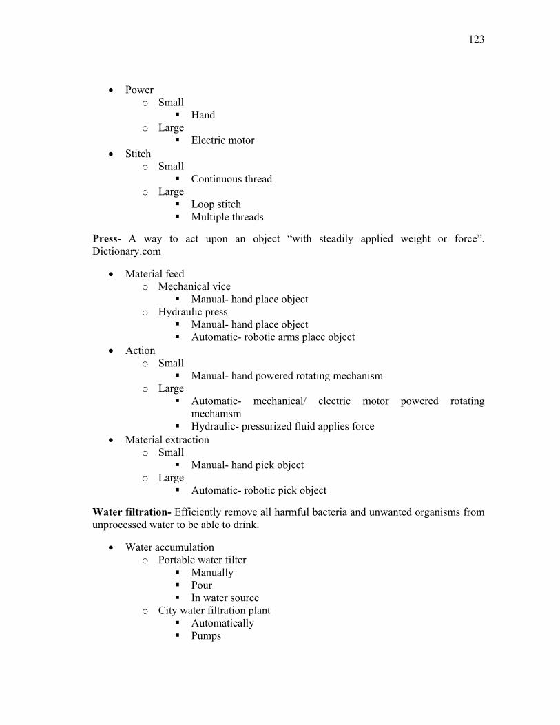
123
Power
o Small
Hand
o Large
Electric motor
Stitch
o Small
Continuous thread
o Large
Loop stitch
Multiple threads
Press- A way to act upon an object “with steadily applied weight or force”.
Dictionary.com
Material feed
o Mechanical vice
Manual- hand place object
o Hydraulic press
Manual- hand place object
Automatic- robotic arms place object
Action
o Small
Manual- hand powered rotating mechanism
o Large
Automatic- mechanical/ electric motor powered rotating
mechanism
Hydraulic- pressurized fluid applies force
Material extraction
o Small
Manual- hand pick object
o Large
Automatic- robotic pick object
Water filtration- Efficiently remove all harmful bacteria and unwanted organisms from
unprocessed water to be able to drink.
Water accumulation
o Portable water filter
Manually
Pour
In water source
o City water filtration plant
Automatically
Pumps
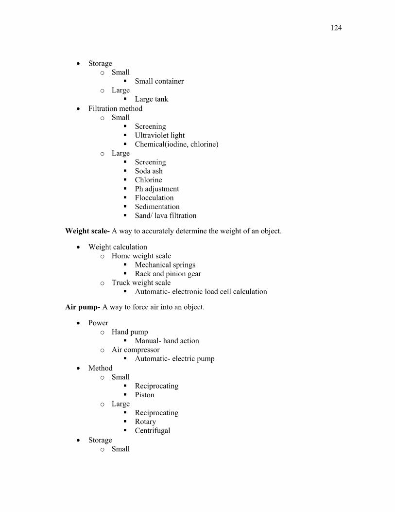
124
Storage
o Small
Small container
o Large
Large tank
Filtration method
o Small
Screening
Ultraviolet light
Chemical(iodine, chlorine)
o Large
Screening
Soda ash
Chlorine
Ph adjustment
Flocculation
Sedimentation
Sand/ lava filtration
Weight scale- A way to accurately determine the weight of an object.
Weight calculation
o Home weight scale
Mechanical springs
Rack and pinion gear
o Truck weight scale
Automatic- electronic load cell calculation
Air pump- A way to force air into an object.
Power
o Hand pump
Manual- hand action
o Air compressor
Automatic- electric pump
Method
o Small
Reciprocating
Piston
o Large
Reciprocating
Rotary
Centrifugal
Storage
o Small
125
Direct air into object
No tank
One way valve
o Large
Pressurized storage tank
No tank
One way valve
Saw- A device that can cut through an object.
Power
o Hand saw
Manual- hand operated
o Chain/ circular saw
Automatic- electric/ gas motor
Method
o Small
Oscillation of arm
o Large
Electric / gas motor rotates cutting chain
Blade
o Small
Serrated teeth
Thin solid body
o Large
Serrated teeth
Thick rotating chain body
Thin rotating circular disk
Drill- A device that can cut a hole into an object.
Power
o Hand powered
Manual- hand operated
o Portable drill
Automatic- electric motor
o Oil well
Automatic- electric/ gas motor
Method
o Small
Rotation of hand
o Medium
Electric motor rotates bit
126
o Large
Gas motor rotates bit
Bit
o Small
Steel
o Medium
High carbon steel
o Large
High carbon steel
Titanium
Lock- A device for securing an object.
Locking mechanism
o Combination lock
Mechanical tumblers
o Safe
Mechanical tumblers
Magnetic
Electronic
Length measure
Length calculation
o Ruler/ tape measure
Manual- visual comparison to markings
o Electronic ruler
Automatic- Time it takes for laser to return to origin determines
length
Watch- A device that calculates time.
Time calculation
o Hourglass
Calculated amount of sand through a hole
o Mechanical watch
Automatic- gears measure seconds, minutes, and hours
Automatic- quartz crystal
o Electronic watch
Automatic- electronic computer chip
Compactor- A means of compacting dirt by vibration/ pounding.
Power
127
o Hand stomper
Manual- hand
o Motorized compactor
Automatic- gasoline motor
o Crane compactor
Automatic- gasoline motor
Method
o Small
Arm lifting and dropping
o Medium
Motor drives rotating arm which moves compactor up and down
o Large
Motor lifts large weight through cables up and down
Trencher- A means of digging a narrow yet deep cut into the earth.
Power
o Plow
Manual- hand
o Trencher
Automatic-gasoline motor
Method
o Small
Pull plow through dirt
Animal pulls plow through dirt
o Large
Motor drives rotating chain which cuts through dirt
Blade
o Small
Large steel plow
o Large
Large rotating serrated chain
Dirt removal- A means of removing dirt.
Power
o Shovel
Manual- hand
o Back hoe
Automatic-gasoline motor
Method
o Small
Dig shovel into ground to remove dirt
o Large
128
Motor drives hydraulic pistons which digs shovel into ground to
remove dirt
Blade
o Small
Small steel shovel
o Large
Large steel bucket with teeth
Earth mover- A means of moving dirt.
Power
o Wheelbarrow
Manual- hand
o Dump truck
Automatic-gasoline motor
Method
o Small
Person pushes mall bucket with wheels
o Large
Motor drives large truck with huge bucket
Motor drives hydraulic pistons which lift one side of bucket to
remove dirt
Bucket
o Small
Small steel dish
o Large
Large steel truck bed
Grain harvesting- Means of gathering and preparing grain for sale
Power
o Scythe
Manual- hand
o Combine harvester
Automatic-gasoline motor
Method
o Small
Swing scythe through grain stalks to cut
Gather grain stalks into sheaves and tie into bunches
Thresh grain by separating cereal grain from chaff
o Large
Motor drives rotating mechanism which cuts stalks
Motor drives auger which feeds grain into elevator
129
Mechanical elevator carries grain to threshing drum
Motor drives threshing drum which separates cereal from chaff
Blade
o Small
Long thin steel blade
o Large
Large rotating metal blades
Cotton picking- Means of picking cotton and seed from plant to use for textiles
Power
o Hand laborers
Manual- hand
o Cotton picker
Automatic-gasoline motor
Method
o Small
Pick cotton lint and seed from stalks by hand
Gather cotton into large containers for travel
o Large
Motor drives rotating rows of barbed spindles which remove seed-
cotton
Motor drives rotating mechanism opposite direction to remove
seed-cotton
Field cultivator- farm implement for stirring and pulverizing the soil, either before
planting or to remove weeds and to aerate and loosen the soil after the crop has begun to
grow.
Power
o Hand cultivator
Manual- hand
o Field cultivator/ tiller
Automatic-gasoline motor
Method
o Small
Dig into soil to loosen
o Large
Motor drives rotating auger
Tool
o Small
Small steel pronged tool
o Large
130
Large steel auger
Bread maker- A means of making bread.
Power
o Hand
Manual- hand
o Home bread maker
Automatic- electric motor
o Industry bread maker
Automatic- electric motor
Mixing
o Small
Hand
o Large
Rotating metal arms
o Larger
Rotating metal arms
Container
o Small
Small bowl
o Large
Medium bowl/ tub
Use as oven
o Larger
Large tub
Baking
o Small
Home oven
o Large
Heating plate/ oven
o Larger
Industrial oven
Blender/ mixer- A means of mixing together various substances.
Power
o Whisk
Manual- hand
o Hand mixer
Automatic- electric motor
o Industrial mixer
Automatic- electric motor
Method
o Small
131
Arm moves whisk rapidly through substance
o Medium
Motor rapidly rotates small steel blades
o Large
Motor rapidly rotates large steel blades
Oven
Coffee grinder- A means of grinding coffee.
Power
o Hand operated
Manual- hand
o Home grinder
Automatic- electric motor
o Industry grinder
Automatic- electric motor
Method
o Small
Arm rotates stone against another stone
o Medium
Motor rotates metal blades
o Large
Motor rotates metal blades
Potato peeler- A means of peeling potatoes.
Power
o Hand peeler
Manual- hand
o Industrial peeler
Automatic- electric motor
Method
o Small
Arm moves sharp blade over potato
o Large
Motor rotates steel tumbler
Juicer- A means of juicing various fruits and vegetables.
Power
o Hand
Manual- hand
o Home juicer
Automatic- electric motor
132
o Industrial juicer
Automatic- electric motor
Method
o Small
Hand squeezes fruit
o Medium
Motor rotates juicing head
o Large
Motor rapidly rotates metal grinding wheel
Energy generator- A means of generating energy.
Power
o Small
Manual- Hand
o Large
Automatic
Gasoline motor
Water
Wind
Method
o Small
Rotate shaft which runs generator
o Large
Motor/ water/ wind rotates shaft which runs generator
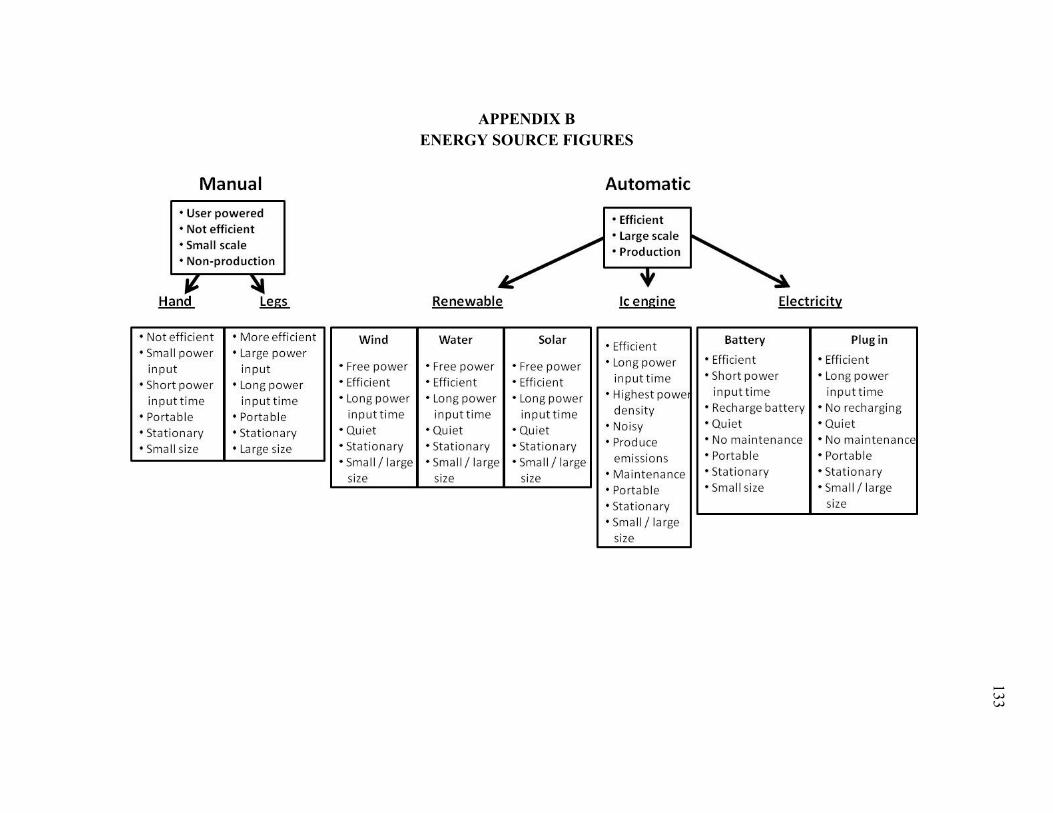
133
APPENDIX B
ENERGY SOURCE FIGURES
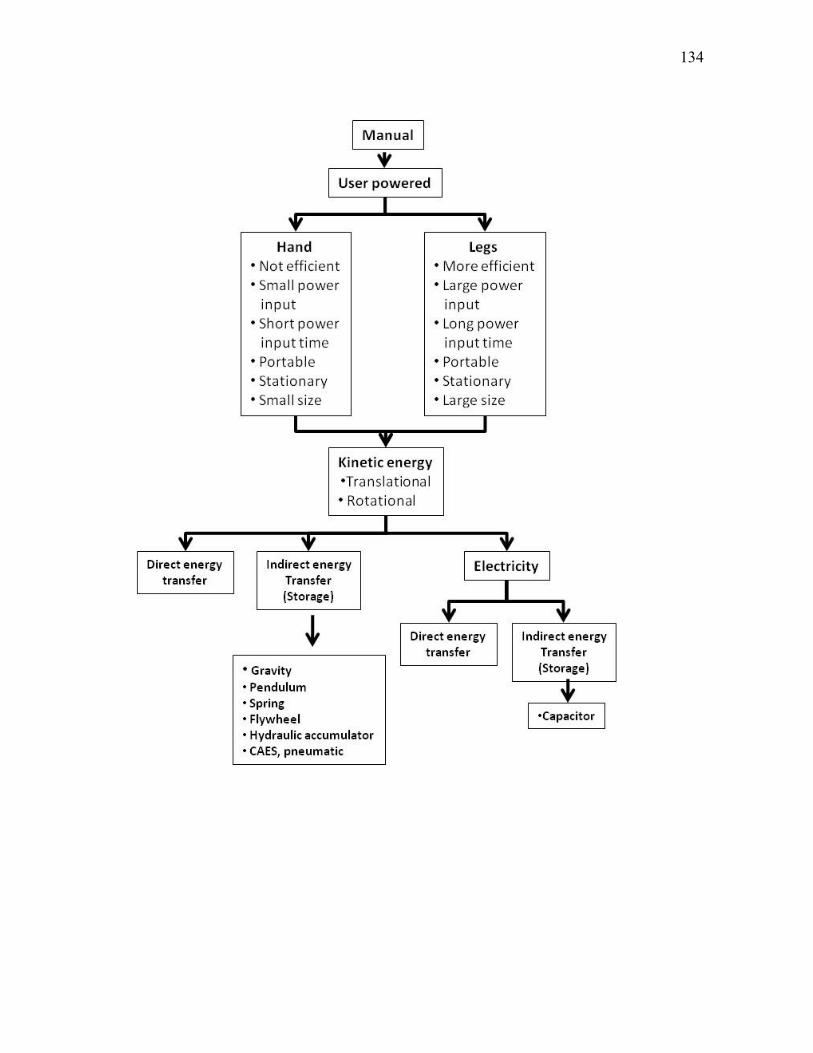
134
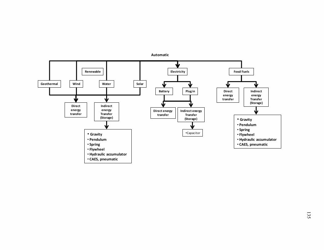
135
Automatic
SolarWind
Plug inBattery
Renewable Fossil fuels
WaterGeothermal
Electricity
Direct energy transfer
Indirect energyTransfer(Storage)
•Capacitor
Direct energy transfer
Indirect energy
Transfer(Storage)
• Gravity
• Pendulum• Spring• Flywheel• Hydraulic accumulator• CAES, pneumatic
Direct energy transfer
Indirect energy
Transfer(Storage)
• Gravity
• Pendulum• Spring• Flywheel• Hydraulic accumulator• CAES, pneumatic
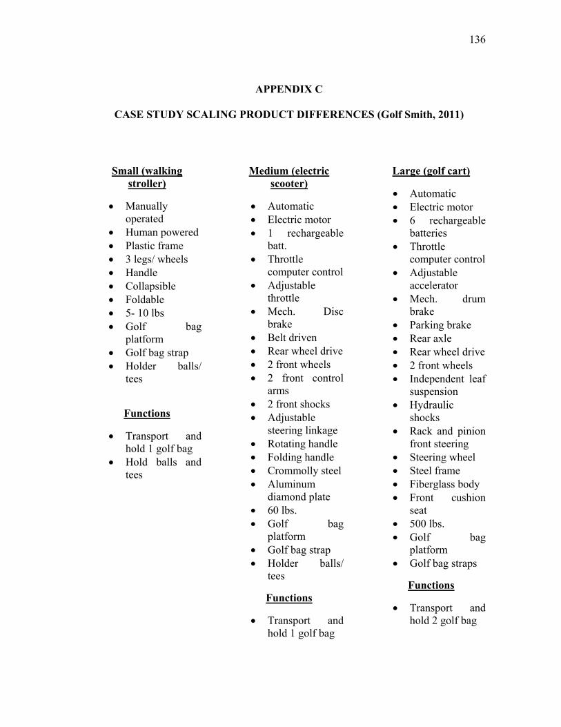
136
APPENDIX C
CASE STUDY SCALING PRODUCT DIFFERENCES (Golf Smith, 2011)
Small (walking
stroller)
Manually
operated
Human powered
Plastic frame
3 legs/ wheels
Handle
Collapsible
Foldable
5- 10 lbs
Golf bag
platform
Golf bag strap
Holder balls/
tees
Functions
Transport and
hold 1 golf bag
Hold balls and
tees
Medium (electric
scooter)
Automatic
Electric motor
1 rechargeable
batt.
Throttle
computer control
Adjustable
throttle
Mech. Disc
brake
Belt driven
Rear wheel drive
2 front wheels
2 front control
arms
2 front shocks
Adjustable
steering linkage
Rotating handle
Folding handle
Crommolly steel
Aluminum
diamond plate
60 lbs.
Golf bag
platform
Golf bag strap
Holder balls/
tees
Functions
Transport and
hold 1 golf bag
Large (golf cart)
Automatic
Electric motor
6 rechargeable
batteries
Throttle
computer control
Adjustable
accelerator
Mech. drum
brake
Parking brake
Rear axle
Rear wheel drive
2 front wheels
Independent leaf
suspension
Hydraulic
shocks
Rack and pinion
front steering
Steering wheel
Steel frame
Fiberglass body
Front cushion
seat
500 lbs.
Golf bag
platform
Golf bag straps
Functions
Transport and
hold 2 golf bag

137
APPENDIX D
TOUR TREK TAHOE CART PARTS LIST
1- Aluminum handle
o Foam grip
o Plastic molded accessory holder
4- Phillips head screws
o 1- plastic adjustable locker
1- metal bolt
1- plastic twist knob
o 1- plastic end cap (connects rods to lower legs)
o 2- metal rods
o 1- plastic pivot point
1-metal bolt
1- aluminum down tube
o 1- plastic endcap
o 1- upper golf bag holder
o 1- upper velcro golf bag strap
1- metal bolt
o 1- metal water bottle holder
2- metal rivets
o 1- plastic lower golf bag holder
1- metal bolt
o 1- lower clip golf bag strap
o 1- front wheel clamp/holder
1- spring action locker
2- metal screws
o 1- metal front wheel arm
o 1- plastic front wheel
1- metal bolt

138
o 1- lower legs pivot support
4- metal rivets
2- large lower legs
2- metal bolts
o 2- small lower legs
2- metal bolts
o 1- metal braided cable
(metal rods)
o 2- rear wheel spindles
8- metal bolts
2- rear wheel locking latches
2- rear wheel parking levers
2- metal rivets
o 2- plastic rear wheels
2- metal/plastic axles with hole for locking
Ring of notches on axle for parking leve
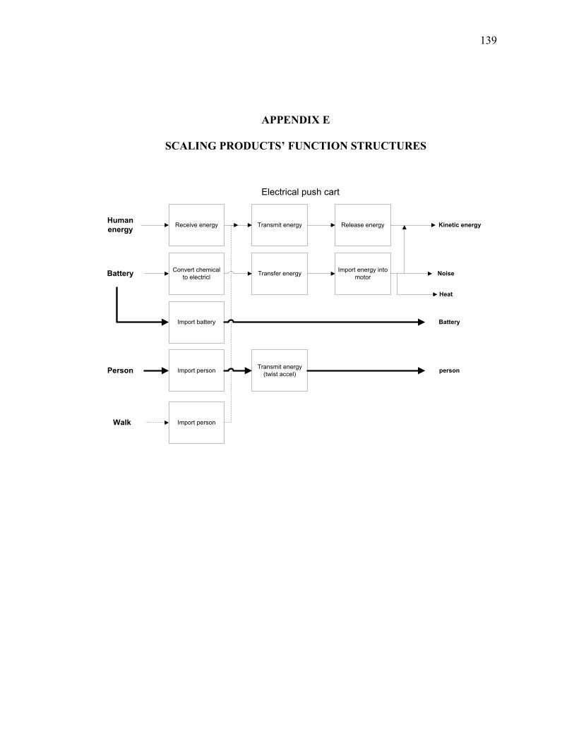
139
APPENDIX E
SCALING PRODUCTS‟ FUNCTION STRUCTURES
Receive energy Transmit energy Release energyHuman
energy
Person
Battery
person
Battery
Heat
Noise
Kinetic energy
Import battery
Convert chemical
to electriclTransfer energy
Import energy into
motor
Import personTransmit energy
(twist accel)
Electrical push cart
Walk Import person
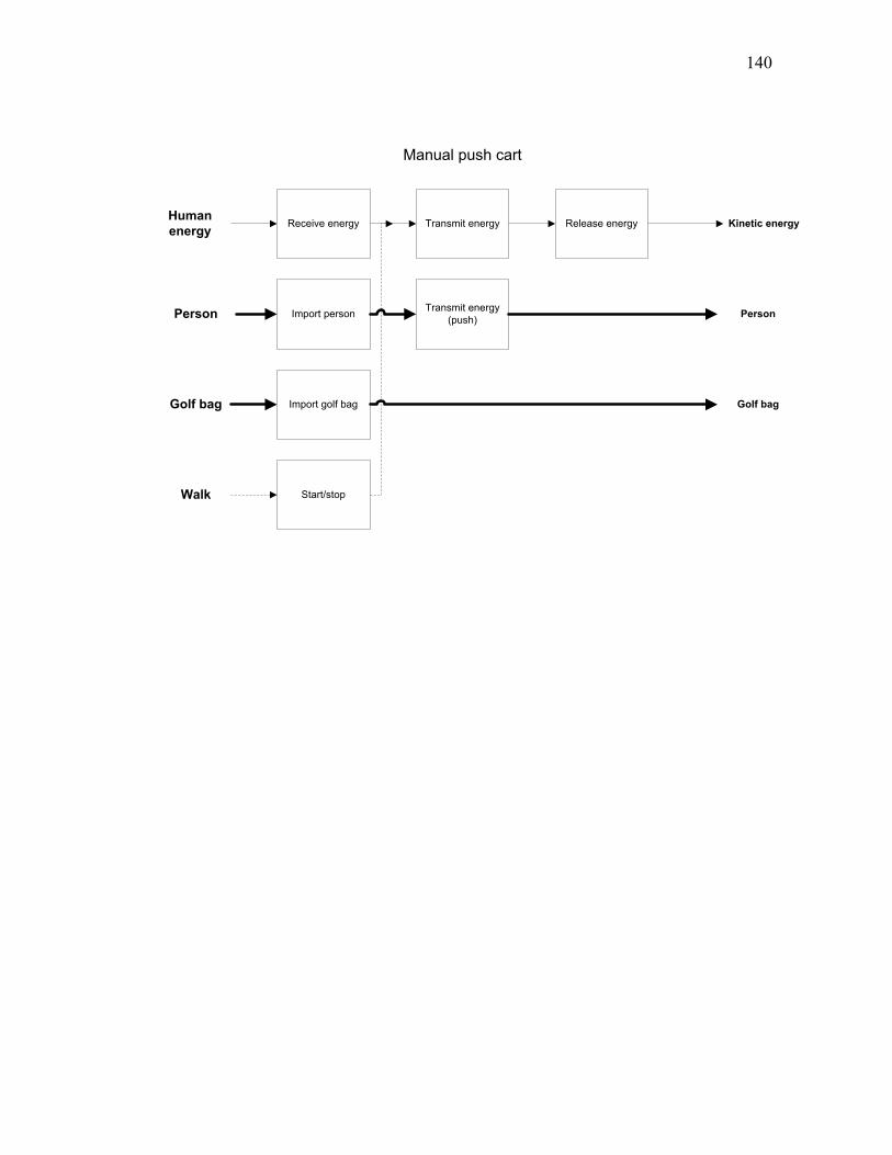
140
Receive energy Transmit energy Release energyHuman
energy
Person Person
Kinetic energy
Import personTransmit energy
(push)
Manual push cart
Golf bag Golf bagImport golf bag
Walk Start/stop
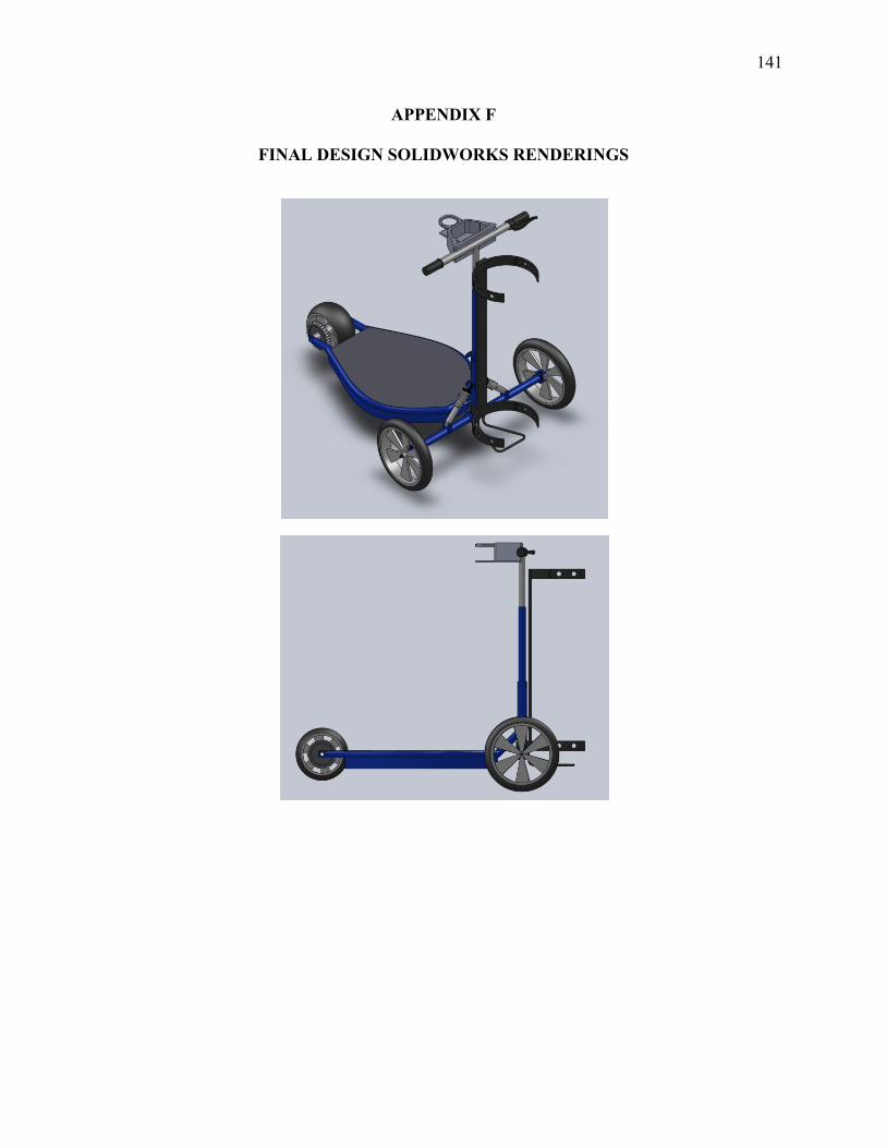
141
APPENDIX F
FINAL DESIGN SOLIDWORKS RENDERINGS
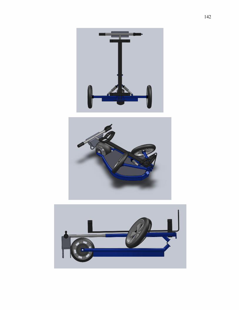
142
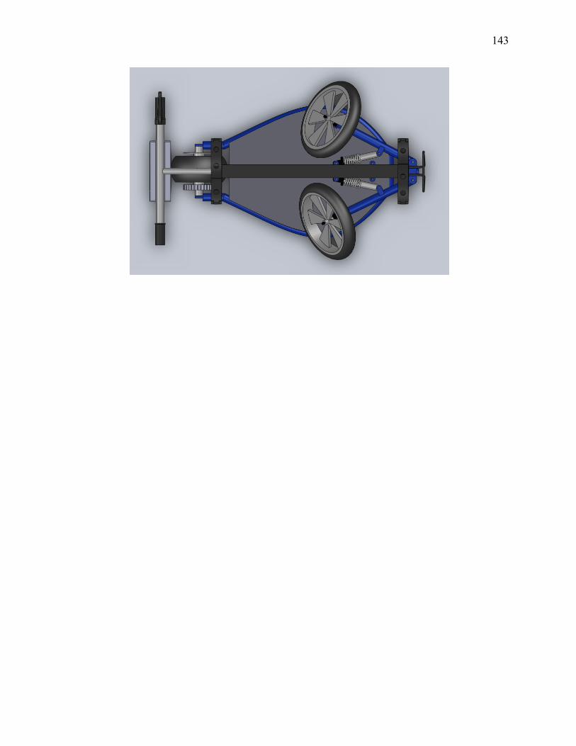
143
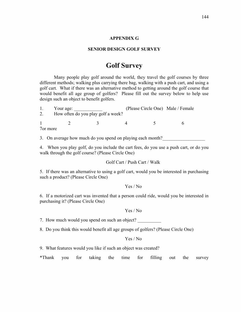
144
APPENDIX G
SENIOR DESIGN GOLF SURVEY
Golf Survey
Many people play golf around the world, they travel the golf courses by three
different methods; walking plus carrying there bag, walking with a push cart, and using a
golf cart. What if there was an alternative method to getting around the golf course that
would benefit all age group of golfers? Please fill out the survey below to help use
design such an object to benefit golfers.
1. Your age: ____________ (Please Circle One) Male / Female
2. How often do you play golf a week?
1 2 3 4 5 6
7or more
3. On average how much do you spend on playing each month?__________________
4. When you play golf, do you include the cart fees, do you use a push cart, or do you
walk through the golf course? (Please Circle One)
Golf Cart / Push Cart / Walk
5. If there was an alternative to using a golf cart, would you be interested in purchasing
such a product? (Please Circle One)
Yes / No
6. If a motorized cart was invented that a person could ride, would you be interested in
purchasing it? (Please Circle One)
Yes / No
7. How much would you spend on such an object? __________
8. Do you think this would benefit all age groups of golfers? (Please Circle One)
Yes / No
9. What features would you like if such an object was created?
*Thank you for taking the time for filling out the survey

145
APPENDIX H
SENIOR DESIGN DECISION MATRIX
Requirements TotalPercent
%
Light weight 0 0 0 1 1 1 1 1 1 1 7 12.73
Compact 1 0 0 1 1 1 1 1 1 1 8 14.55
Easy to use 1 1 1 1 1 1 1 1 1 1 10 18.18
Comfortable 1 1 0 1 1 1 1 1 1 1 9 16.36
Affordable 0 0 0 0 1 00 1 1 1
4 7.27
Appearance 0 0 0 0 00 0 0 0 1
1 1.82
Low Maintenance 0 0 0 0 11 0 1 1 1
5 9.09
Durability 0 0 0 01 1 1 1 1 1
6 10.91
Fast 0 0 0 00 1 0 0 1 1
3 5.45
Fast Charge Time0 0 0 0 0 1 0 0 0 1 2
3.64
Accessories0 0 0 0 0 0 0 0 0 0 0
0.00
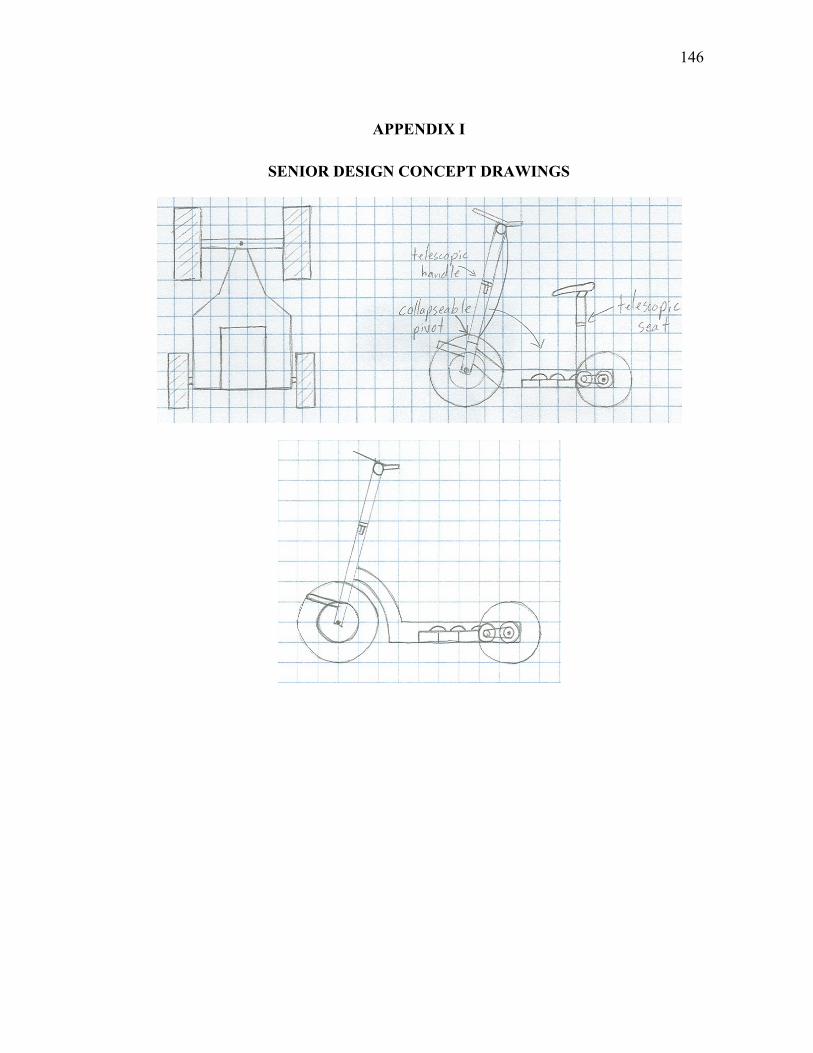
146
APPENDIX I
SENIOR DESIGN CONCEPT DRAWINGS
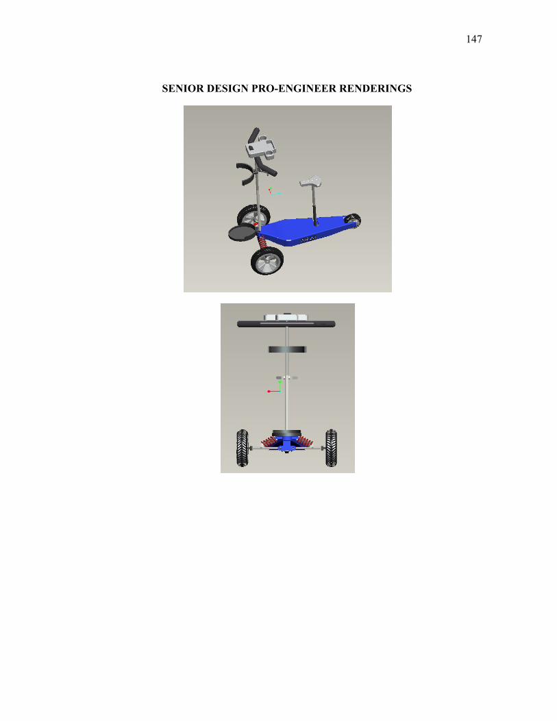
147
SENIOR DESIGN PRO-ENGINEER RENDERINGS
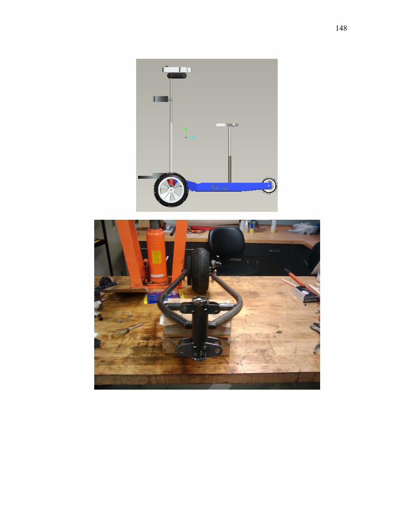
148
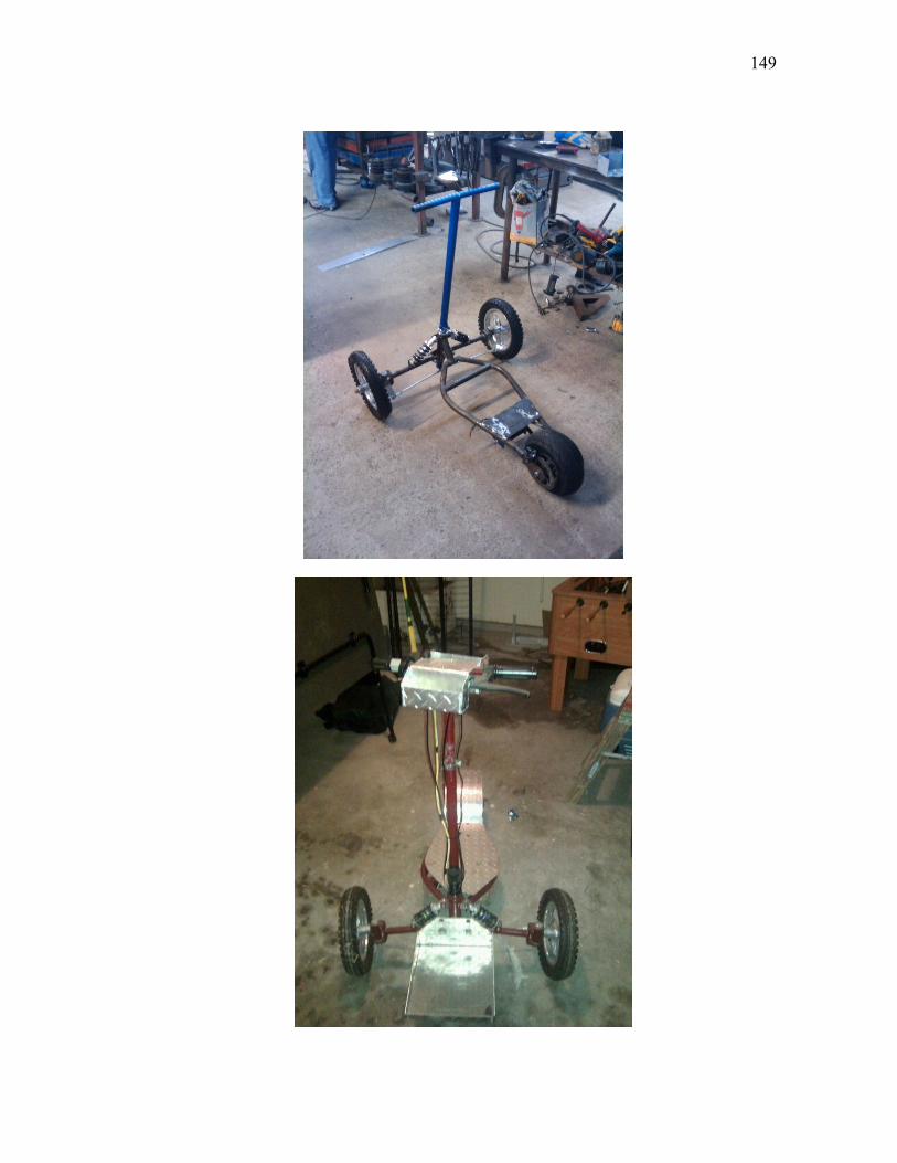
149
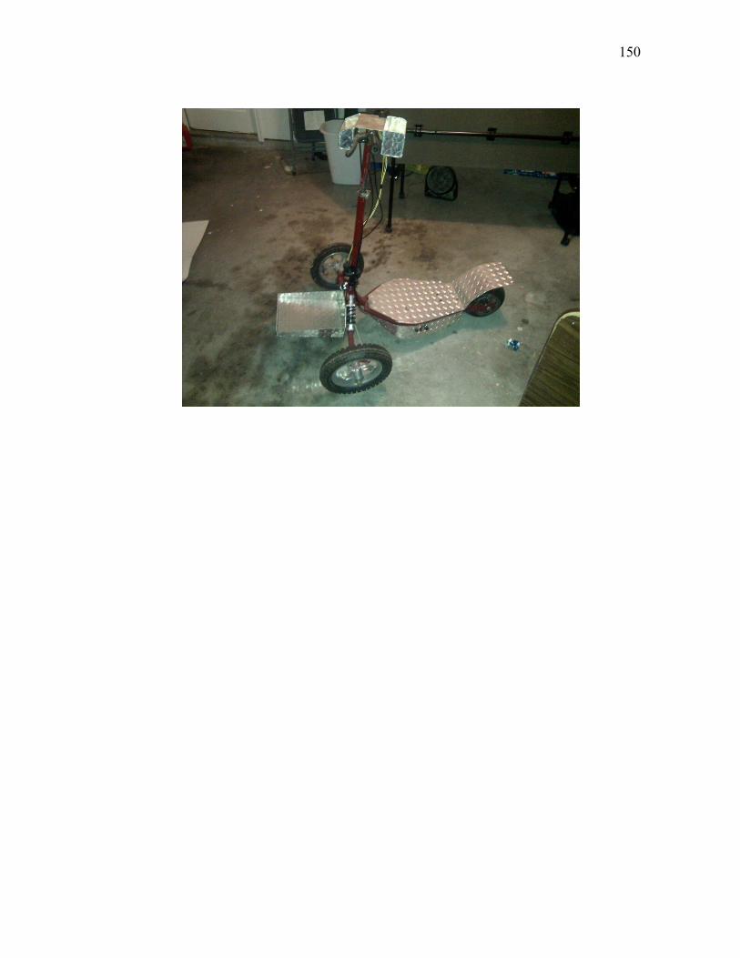
150
151
VITA
Angel Gerardo Perez obtained his Bachelor of Science degree in mechanical
engineering from The University of Texas Pan American in December 2008. He pursued
graduate studies at Texas A&M University in mechanical engineering and received his
Master of Science degree in August 2011. His research interest includes design-by-
analogy and idea generation.
Permanent Address:
Department of Mechanical Engineering, ENPH, 3123
TAMU, College Station, Texas 77843, USA.
Email: [email protected]