Embed Size (px)
Citation preview
Illustration ©ESA
Outline
1. Mission Goal
2. Gravity Sensor System
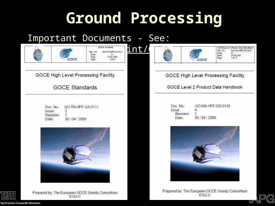
3. Ground Processing
4. Conclusions
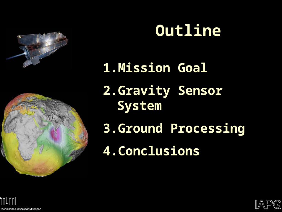
Dynamic Ocean Topography
The Geoid
Equipotential Surface
Reference of Physical Height Systems
Geoid
Topography
Ellipsoid
Mean Ocean Surface
Geometric Height
Physical Height
Sea Surface Height
Geoid Height
Mission Goal
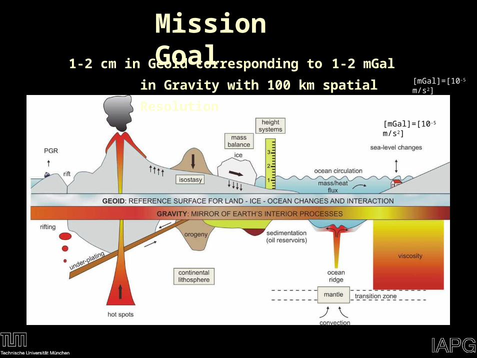
Mission Goal
[mGal]=[10-5 m/s2]
1-2 cm in Geoid corresponding to 1-2 mGal in Gravity
with 100 km spatial Resolution [mGal]=[10-5 m/s2]
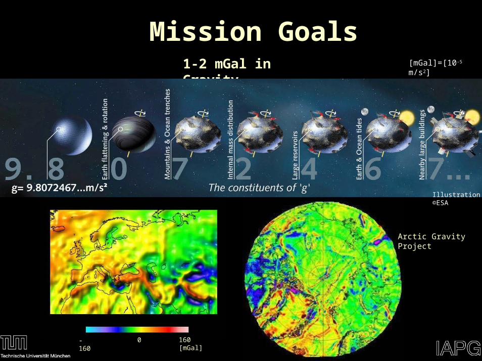
Mission Goals1-2 mGal in Gravity [mGal]=[10-5 m/s2]
Illustration ©ESA
-160 0 160 [mGal]
Arctic Gravity Project
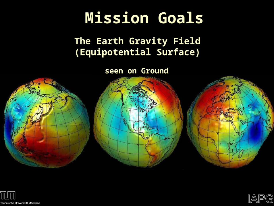
Mission GoalsThe Earth Gravity Field (Equipotential Surface)
seen on Ground
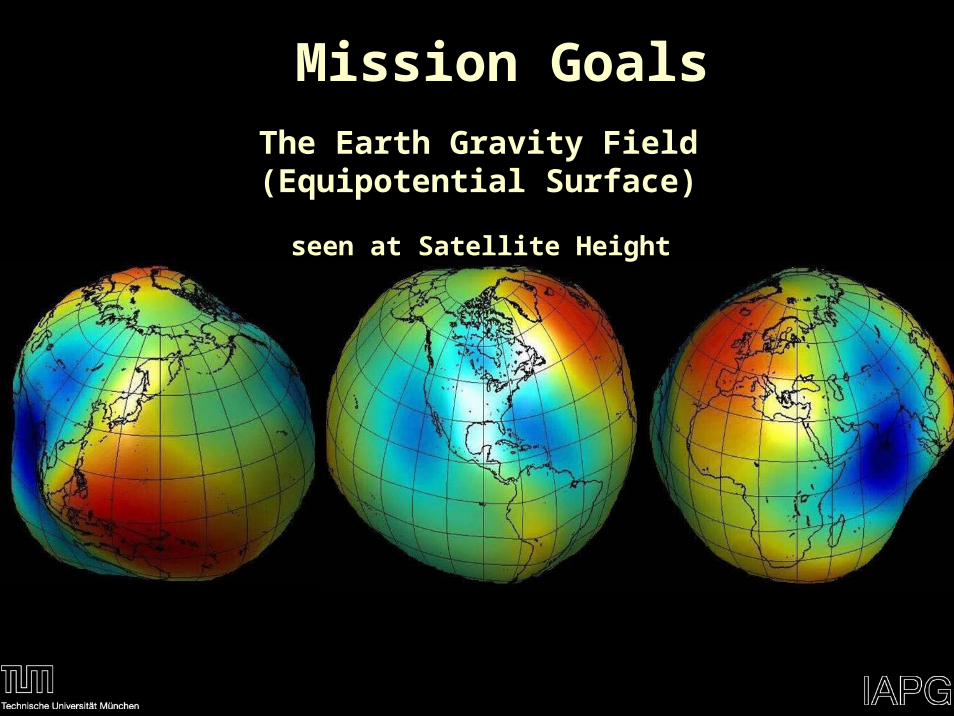
The Earth Gravity Field (Equipotential Surface)
seen at Satellite Height
Mission Goals
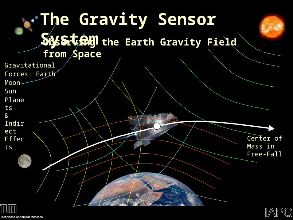
Observing the Earth Gravity Field from Space
Gravitational Forces: EarthMoon SunPlanets& Indirect Effects
Center of Mass in Free-Fall
The Gravity Sensor System
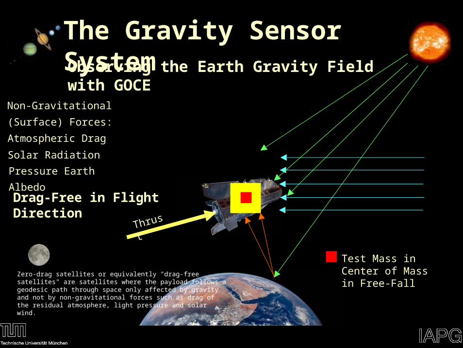
Non-Gravitational (Surface) Forces:
Atmospheric Drag
Solar Radiation Pressure
Earth Albedo
Test Mass in Center of Mass in Free-Fall
Thrust
Drag-Free in Flight Direction
The Gravity Sensor SystemObserving the Earth Gravity Field with GOCE
Zero-drag satellites or equivalently "drag-free satellites" are satellites where the payload follows a geodesic path through space only affected by gravity and not by non-gravitational forces such as drag of the residual atmosphere, light pressure and solar wind.
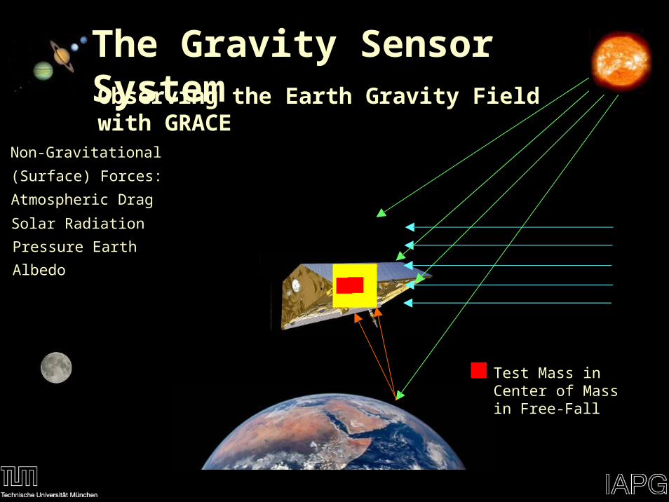
Non-Gravitational (Surface) Forces:
Atmospheric Drag
Solar Radiation Pressure
Earth Albedo
Test Mass in Center of Mass in Free-Fall
The Gravity Sensor SystemObserving the Earth Gravity Field with GRACE
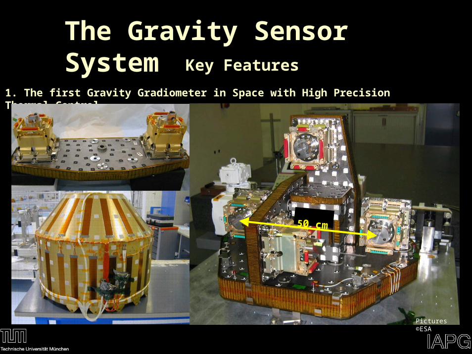
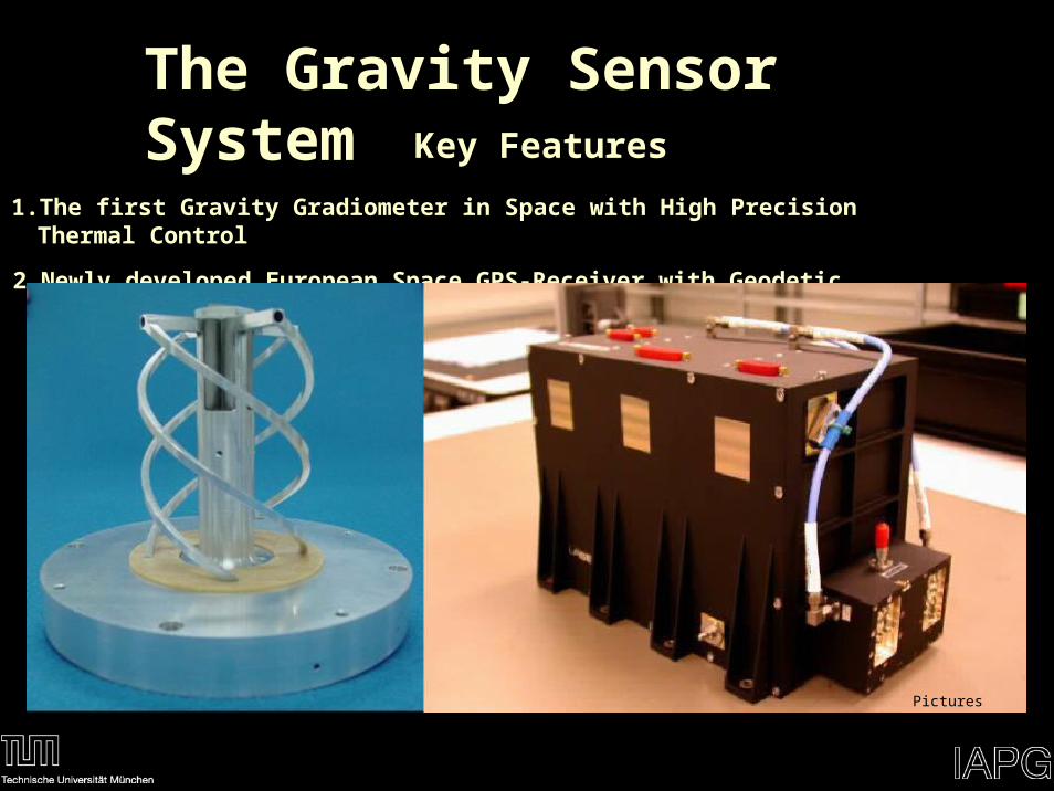
The Gravity Sensor SystemKey Features
1. The first Gravity Gradiometer in Space with High Precision Thermal Control
50 cm
Pictures ©ESA
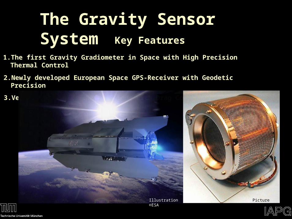
The Gravity Sensor SystemKey Features
1. The first Gravity Gradiometer in Space with High Precision Thermal Control
2. Newly developed European Space GPS-Receiver with Geodetic Precision
Pictures ©ESA
The Gravity Sensor SystemKey Features
1. The first Gravity Gradiometer in Space with High Precision Thermal Control
2. Newly developed European Space GPS-Receiver with Geodetic Precision
3. Very Low Orbit in 260 km Height with Drag Compensation
Illustration ©ESA Picture ©ESA
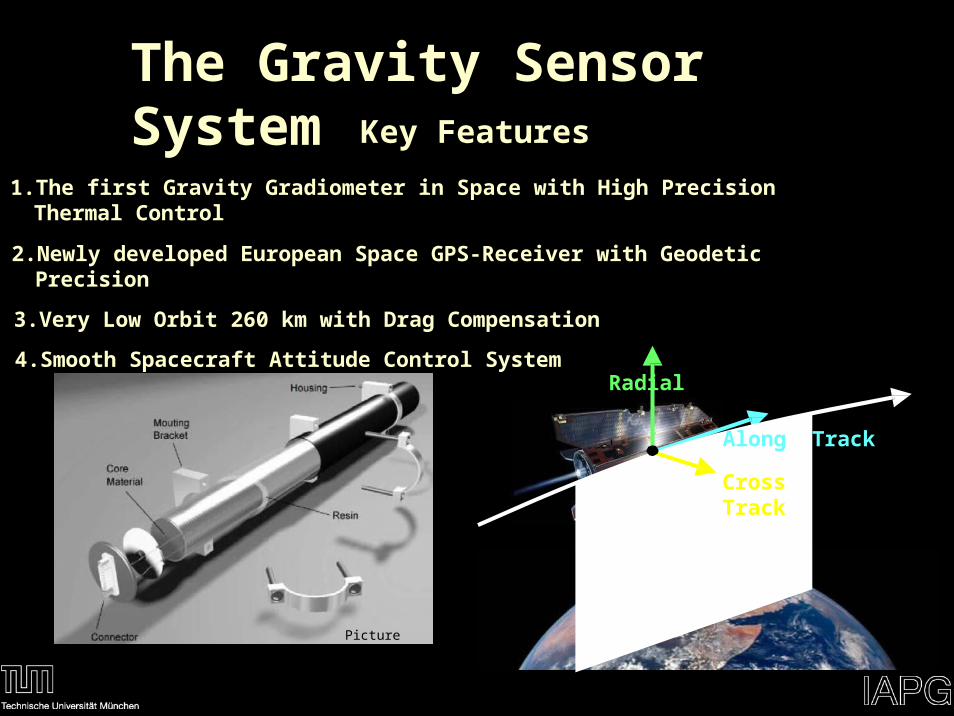
The Gravity Sensor SystemKey Features
1. The first Gravity Gradiometer in Space with High Precision Thermal Control
2. Newly developed European Space GPS-Receiver with Geodetic Precision
3. Very Low Orbit 260 km with Drag Compensation
4. Smooth Spacecraft Attitude Control SystemRadial
Along Track
Cross Track
Picture ©ESA
INCOSE 2008 System Engineering for our Planet, Utrecht, The Netherlands, Academic Forum, 17.6.2008
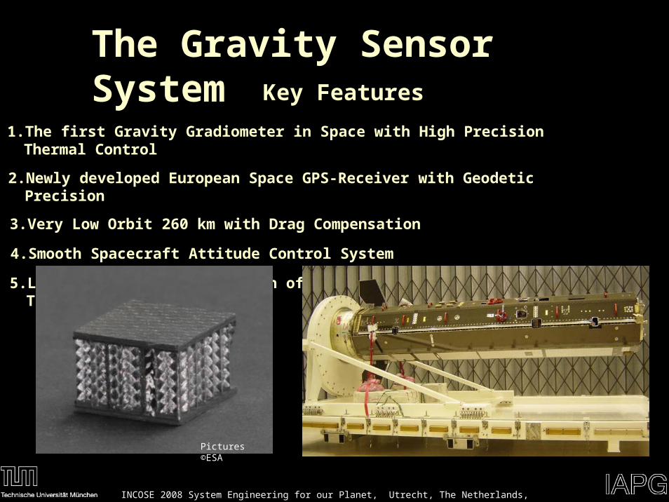
The Gravity Sensor SystemKey Features
1. The first Gravity Gradiometer in Space with High Precision Thermal Control
2. Newly developed European Space GPS-Receiver with Geodetic Precision
3. Very Low Orbit 260 km with Drag Compensation
4. Smooth Spacecraft Attitude Control System
5. Largest Carbon Construction of a Satellite for Stiffness and Thermal Stability
Pictures ©ESA
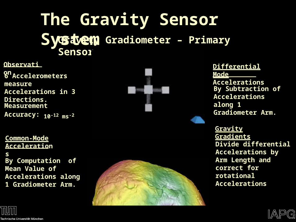
The Gravity Sensor SystemGravity Gradiometer – Primary Sensor
Observation
6 Accelerometers measure Accelerations in 3 Directions.
Measurement Accuracy:
10-12 ms-2
Differential Mode Accelerations
By Subtraction of Accelerations along 1 Gradiometer Arm.
Gravity Gradients
Divide differential Accelerations by Arm Length and correct for rotational Accelerations
Common-Mode Accelerations
By Computation of Mean Value of Accelerations along 1 Gradiometer Arm.
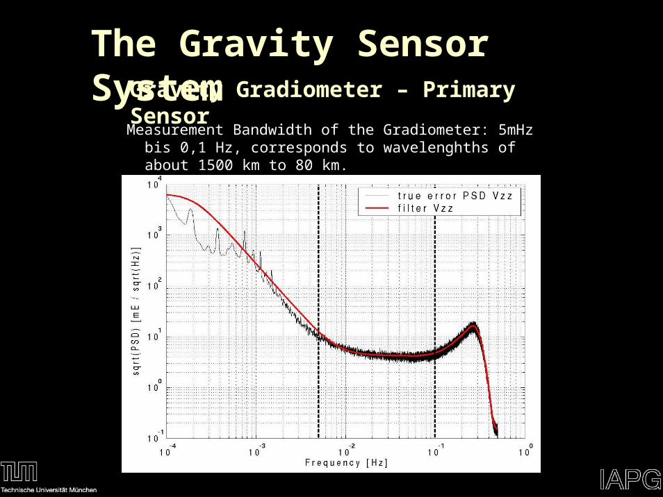
Measurement Bandwidth of the Gradiometer: 5mHz bis 0,1 Hz, corresponds to wavelenghths of about 1500 km to 80 km.
The Gravity Sensor SystemGravity Gradiometer – Primary Sensor
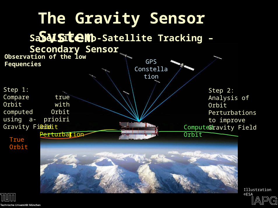
The Gravity Sensor SystemSatellite-to-Satellite Tracking – Secondary Sensor
Illustration ©ESA
Step 1:Compare true Orbit with computed Orbit using a- prioiri Gravity Field
Step 2:Analysis of Orbit Perturbations to improve Gravity Field
Computed Orbit
True Orbit
Orbit Perturbation
GPSConstellatio
n
Observation of the low Fequencies
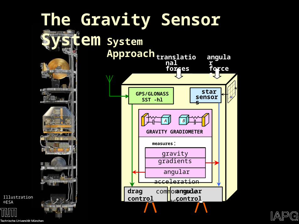
The Gravity Sensor SystemSystem Approach
translational forces
angular forces
star sensors
drag control
*
*
angular control
GPS/GLONASSSST -hl
A B
GRAVITY GRADIOMETER
measures:
gravity gradients
angular
acceleration
common mode acc.Illustration ©ESA
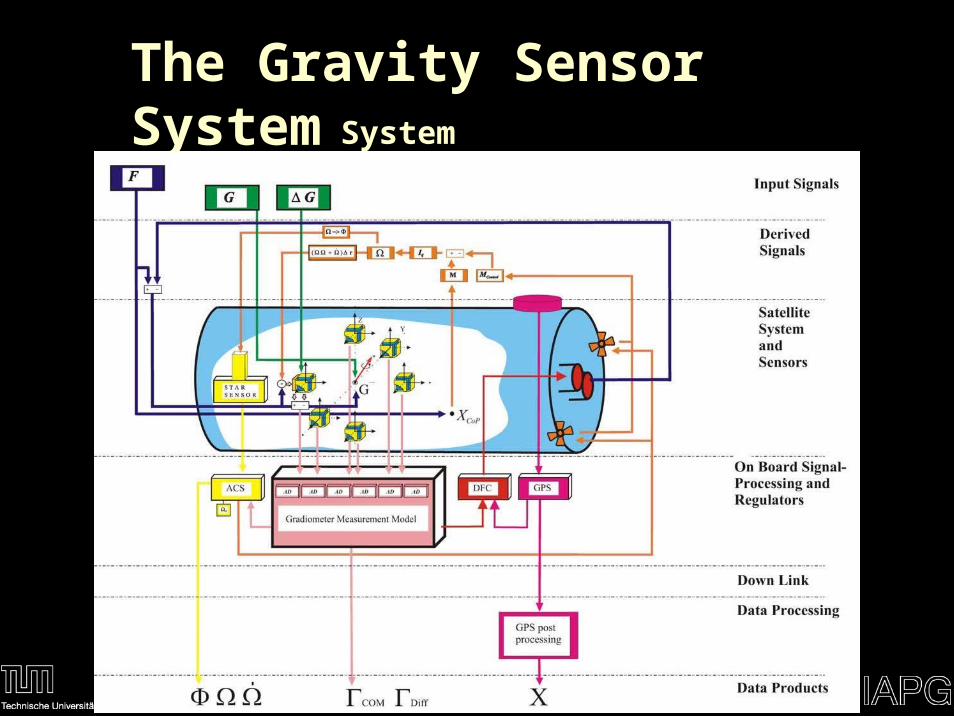
The Gravity Sensor SystemSystem Approach
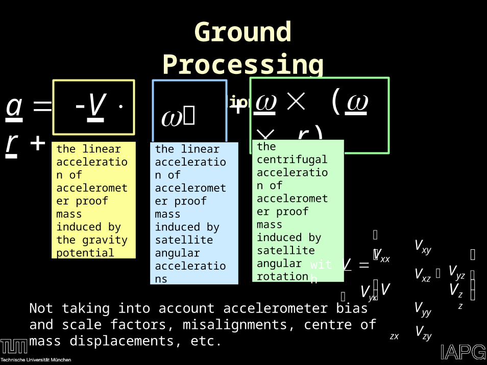
Ground ProcessingGradiometry
( r)a V r r the linear acceleration of accelerometer proof mass induced by satellite angular accelerations
the centrifugal acceleration of accelerometer proof mass induced by satellite angular rotation
the linear acceleration of accelerometer proof mass induced by the gravity potential
Not taking into account accelerometer bias and scale factors, misalignments, centre of mass displacements, etc.
⎛Vxx
Vxy
Vxz ⎞
Vyy
zx Vzy
V
⎜ Vyx
Vyz ⎟zzV V
⎜ ⎟
⎜ ⎟⎝ ⎠
with
Ground Processing
V Vxx xy xz ⎟
V 0 y za rz yx
⎟⎟ ⎪
⎜ x ⎟
⎜ a
⎟
⎨
⎜ V
V V⎟ ⎜ yx yy yz ⎟
Vzy
0
⎟ ⎬ ⎜ r y z
y
⎟
z x
⎟
x
y⎟ ⎪
⎜ y ⎟0⎝ a z
⎠⎝ V
x
Vzz 2 2 ⎟
⎝
r
y xz z x
z
x y
⎠⎭
⎪
⎟
⎜⎜
⎛ ⎞ ⎞⎜ ⎟
⎪
⎪ ⎜⎪
⎜ ⎜ ⎟ ⎜⎟
⎪
⎜
⎜ ⎜ ⎜⎪
⎜ ⎜
⎟⎟
⎜⎟
⎟⎠ ⎟ ⎪
⎜
⎟
⎜⎜⎝ ⎠⎠⎪
⎩
⎝
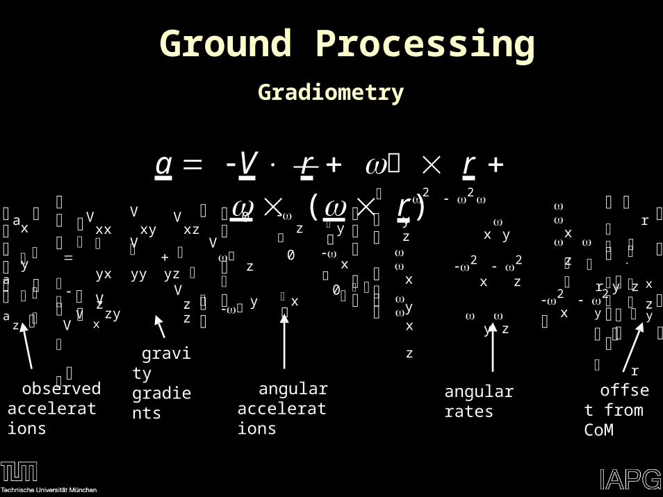
Gradiometry
a V r r ( r)⎛ 2 2
x y
2 2
x z
y z
x
z
⎧
⎛
⎞⎫
⎛
⎞⎛⎞
angular ratesangular accelerations
observed accelerations
gravity gradients
offset from CoM
A
A
A3
A4
A6
A2
X5
X 3
X1
X6
X2
X 4
Z1
Z6 Z 5
Z 3
Z 4
Z2
Y1
Y6 Y5
Y3
Y4
Y2
O5
O1
O6
O2
O4
O3
1
5
OGRF
ZGRFYGR
F
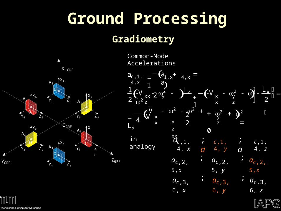
Gradiometry
Common-Mode AccelerationsX GRF
1,x 4,x
c,1,4,x
V 2 2 V 2 2 Lx xxx y z xx y z
V 2 2 Vy
z
xx
2 2 0 Lx xx y z
1
2
a a a
L1
2 1
2 2 2 ⎠
4
⎛ ⎞ ⎜ ⎟⎝
Ground Processing
c,1,4, y
c,1,4, x
c,1,4, z
;a
;a
ain analogy
ac,2,5,x ac,2,5, y ac,2,5,x; ;
ac,3,6, yac,3,6,
x
ac,3,6,
z
; ;
A
A
A3
A4
A6
A2
X5
X 3
X1
X6
X2
X 4
Z1
Z6 Z 5
Z 3
Z 4
Z2
Y1
Y6 Y5
Y3
Y4
Y2
O5
O1
O6
O2
O4
O3
1
5
OGRF
X GRF
ZGRFYGR
F
a 1 a a
x
d,1,4,x 1,x 4,x
V 2 2
y
z
V 2 2 Lx 1 x
xx xx y z
2V 22 22 V 2 2
Lx
Lxxx y z xx y z
2L
12 2 2 2 ⎠
4 2
⎛ ⎞ ⎜ ⎟⎝
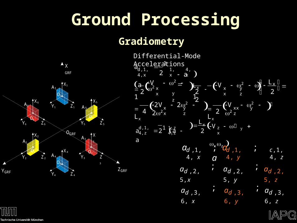
GradiometryDifferential-Mode Accelerations
a 1 a a V y x z
d,1,4,z
1,z 4,z zxL
2 2
Ground Processing
d ,1,4, y
d ,1,4, x
c,1,4, z
; a ; aa
ad ,2,5,x ad ,2,5,
y
ad ,2,5,
z
; ;
ad ,3,6,
y
ad ,3,6,
x
ad ,3,6,
z
; ;
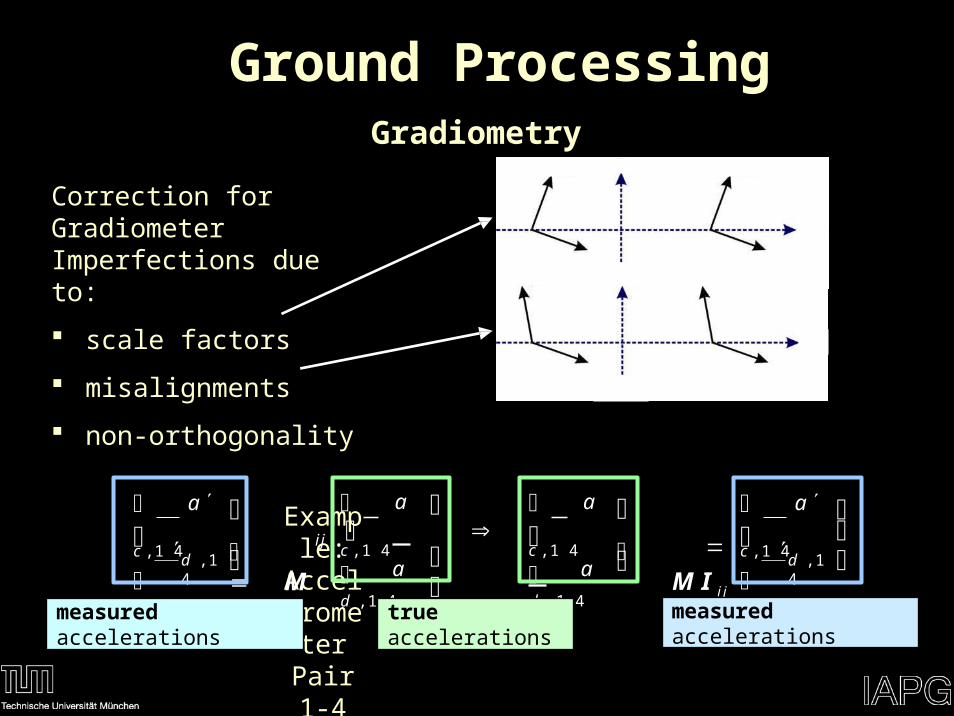
Ground ProcessingGradiometry
Correction for Gradiometer Imperfections due to:
scale factors
misalignments
non-orthogonality
Example:
Accelerometer Pair 1-
4
⎛ a
c ,1 4
⎛ a
c ,1 4
⎛ a
c ,1 4
⎛ a
c ,1 4d ,1 4
d ,1 4⎝ a d
,1 4
⎝ a d
,1 4
i j ⎟ M I i j ⎝
a
⎝
a
⎟ M
⎞⎜
⎟⎠
⎞⎞ ⎞⎜ ⎜ ⎜ ⎟
⎠⎠ ⎠
measured accelerations true accelerations measured accelerations
A
A
A3
A4
A6
A2
X5
X 3
X1
X6
X2
X 4
Z1
Z6 Z 5
Z 3
Z 4
Z2
Y1
Y6 Y5
Y3
Y4
Y2
O5
O1
O6
O2
O4
O3
1
5
OGRF
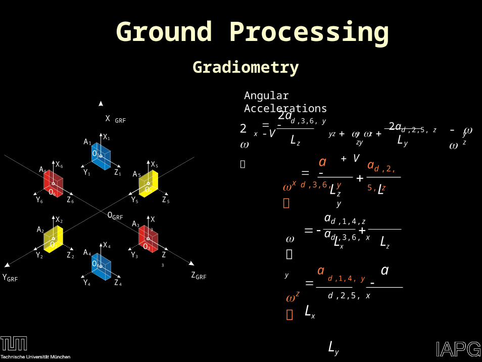
Gradiometry
Angular AccelerationsX GRF
ZGRFYGR
F
Ground Processing
2a - d ,3,6, y -V
2ad ,2,5, z V2
- x yz y z zy y zz yL L
a -d ,3,6, y
ad ,2,5,
zz y
xL L
ad ,1,4,z ad ,3,6,
x
y
Lx Lz
a a d ,1,4, y d ,2,5,
x
Lx
Ly
z
2ad ,1,4,
xV
2 2
y
zxx
Lx
2ad ,2,5, y
V 2 2
x
zyy
Ly
2ad ,3,6, z
V 2 2
x
yzz
Lz
a a d ,1,4, y d ,2,5, x
x yLx Ly
xyV
a a d ,1,4, z d ,3,6, x
xzLx Lz
x zV
a a d ,2,5, z d ,3,6, y
y zLy Lz
zyV
Angular Rate Reconstruction
Ground ProcessingGradiometry
A
A5
A3
A 4
A6
A2
X5
X
X1
X6
X
X 4
Z1
O6
Y6
Z6
O5
Y5 Z 5
Z 3
Z
Z2
Y1
Y3
Y
Y2
O1
O2
O4
O3
1
2
4 4
3OGRF
X GRF
ZGRFYGRF
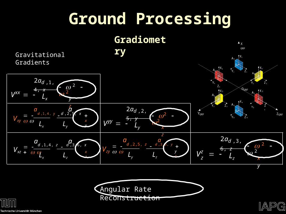
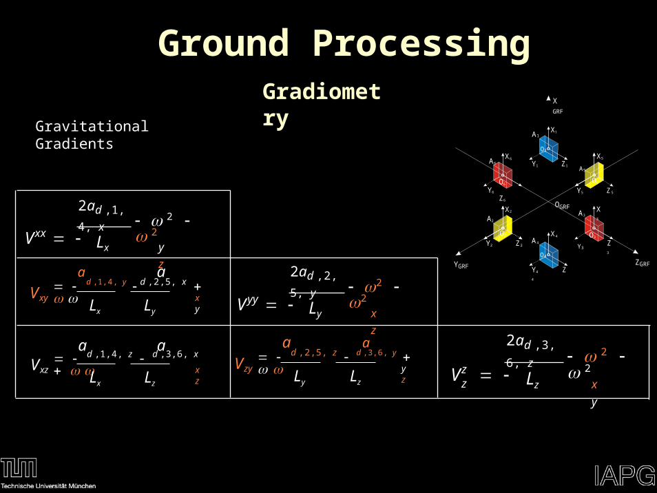
Gravitational Gradients
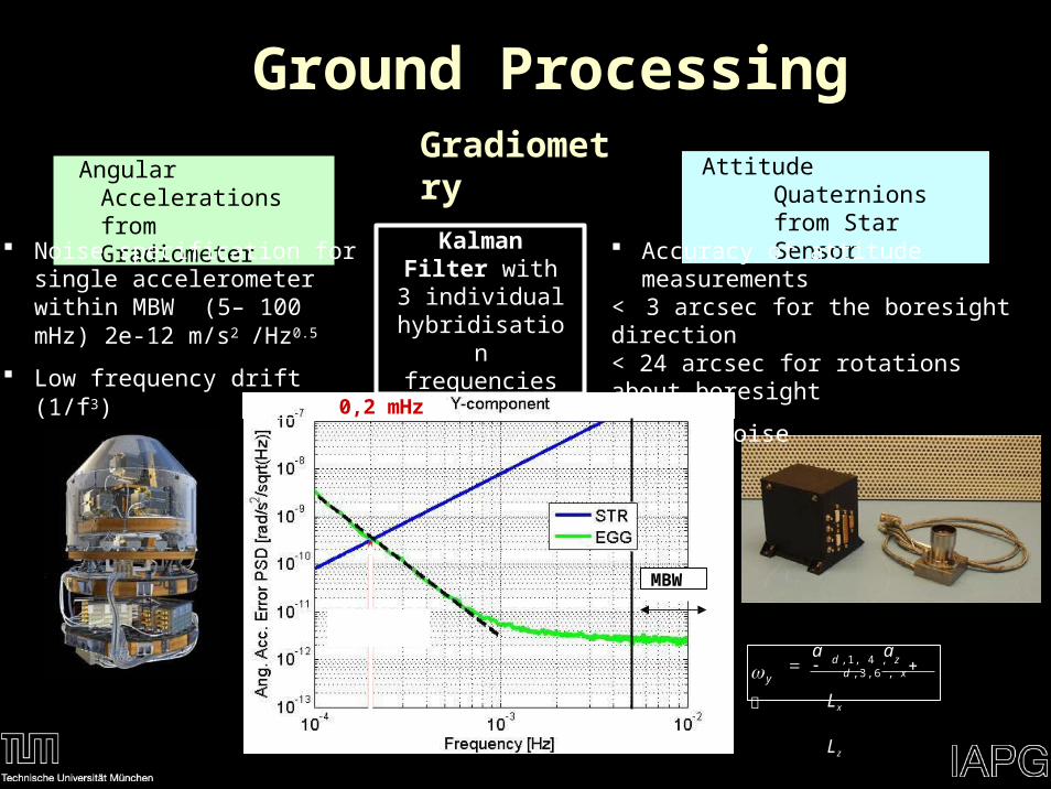
Angular Accelerations from Gradiometer
Noise specification for single accelerometer within MBW (5– 100 mHz) 2e-12 m/s2 /Hz0.5
Low frequency drift (1/f3)
Attitude Quaternions from Star Sensor
Accuracy of attitude measurements< 3 arcsec for the boresight direction< 24 arcsec for rotations about boresight
White noise
0,2 mHz
Kalman Filter with 3 individual
hybridisation frequencies
a a d ,1, 4 , z d ,3,6 ,
x
Lx
L z
y
MBW
Ground ProcessingGradiometry
Ground Processing
2ad ,1,4,
xV
2 2
y
zxx
Lx
2ad ,2,5, y
V 2 2
x
zyy
Ly
2ad ,3,6, z
V 2 2
x
yzz
Lz
a a d ,1,4, y d ,2,5, x
x yLx Ly
xyV
a a d ,1,4, z d ,3,6, x
xzLx Lz
x zV
a a d ,2,5, z d ,3,6, y
y zLy Lz
zyV
Gradiometry
A
A5
A3
A 4
A6
A2
X5
X 3
X1
X6
X2
X 4
Z1
O6
Y6
Z6
O5
Y5 Z 5
Z 3
Y4 Z 4
Z2
Y1
Y3Y2
O1
O2
O4
O3
1
OGRF
X GRF
ZGRFYGR
F
Gravitational Gradients
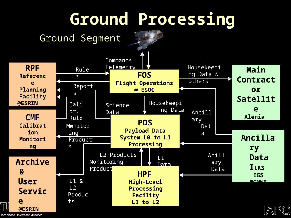
FOSFlight Operations
@ ESOC
Commands Telemetry
PDSPayload Data System L0 to L1 Processing
@ ESRIN
HPFHigh-Level Processing
FacilityL1 to L2 Processing
@ EGG-C
Science Data Housekeeping Data
L1 DataL2 Products Monitoring Products
Ancillary Data ILRS
IGS ECMWFOther
Main Contractor
SatelliteAlenia
Housekeeping Data & others
Anillary Data
AncillaryData
RPFReference Planning Facility
@ESRIN
CMFCalibration Monitoring
Facility@ESRIN
Archive& User Service@ESRIN
Reports
Rules
Monitoring Products
L1 & L2Products
Calibr. Rules
Ground ProcessingGround Segment
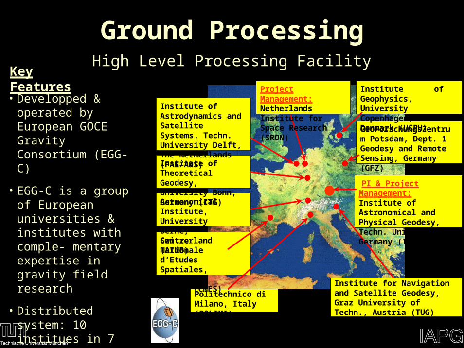
Ground ProcessingHigh Level Processing Facility
Astronomical Institute, University Berne, Switzerland (AIUB)
Centre Nationale d‘Etudes Spatiales, Toulouse, France (CNES)
Politechnico di Milano, Italy (POLIMI)
PI & Project Management: Institute of Astronomical and Physical Geodesy, Techn. Univ. Munich, Germany (IAPG)
Institute for Navigation and Satellite Geodesy, Graz University of Techn., Austria (TUG)
Institute of Theoretical Geodesy, University Bonn, Germany (ITG)
Institute of Astrodynamics and Satellite Systems, Techn. University Delft, The Netherlands (FAE/A&S)
Project Management: Netherlands Institute for Space Research (SRON)
Institute of Geophysics, University Copenhagen, Denmark (UCPH)
GeoForschungsZentrum Potsdam, Dept. 1 Geodesy and Remote Sensing, Germany (GFZ)
Key Features
• Developped & operated by European GOCE Gravity Consortium (EGG-C)
• EGG-C is a group of European universities & institutes with comple- mentary expertise in gravity field research
• Distributed system: 10 institues in 7 countries
• Independent validation by overlap of expertise
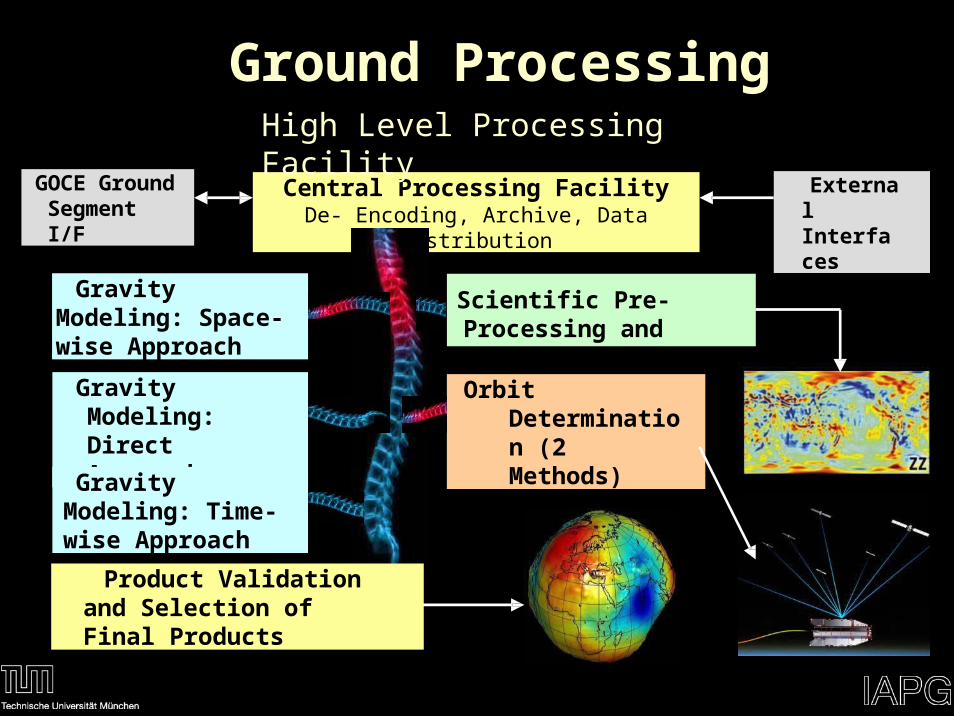
Central Processing FacilityDe- Encoding, Archive, Data Distribution
Scientific Pre-Processing and External Calibration
Orbit Determination (2 Methods)
External Interfaces
GOCE Ground Segment I/F
Gravity Modeling: Direct Approach
Gravity Modeling: Time-wise Approach
Gravity Modeling: Space-wise Approach
Product Validation and Selection of Final Products
Ground ProcessingHigh Level Processing Facility
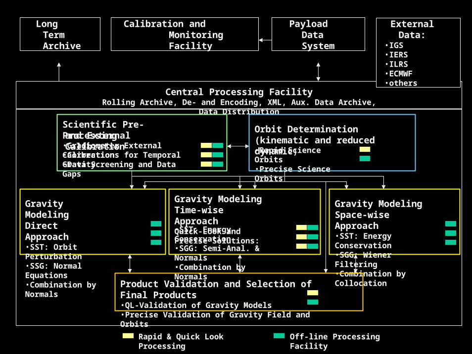
Central Processing FacilityRolling Archive, De- and Encoding, XML, Aux. Data Archive, Data Distribution
Gravity Modeling Time-wise ApproachQuick-Look and Precise Solutions:•SST: Energy Conservation•SGG: Semi-Anal. & Normals•Combination by Normals
Gravity Modeling Space-wise Approach•SST: Energy Conservation•SGG: Wiener Filtering•Combination by Collocation
Gravity Modeling Direct Approach•SST: Orbit Perturbation•SSG: Normal Equations•Combination by Normals
Scientific Pre-Processingand External Calibration
•Gradiometer External Calibration•Corrections for Temporal Gravity•Data Screening and Data Gaps
Orbit Determination(kinematic and reduced dynamic)•Rapid Science Orbits•Precise Science Orbits
Product Validation and Selection of Final Products•QL-Validation of Gravity Models•Precise Validation of Gravity Field and Orbits
Rapid & Quick Look Processing Off-line Processing Facility
Long Term Archive
Calibration and Monitoring Facility
Payload Data System
External Data:•IGS•IERS•ILRS•ECMWF•others
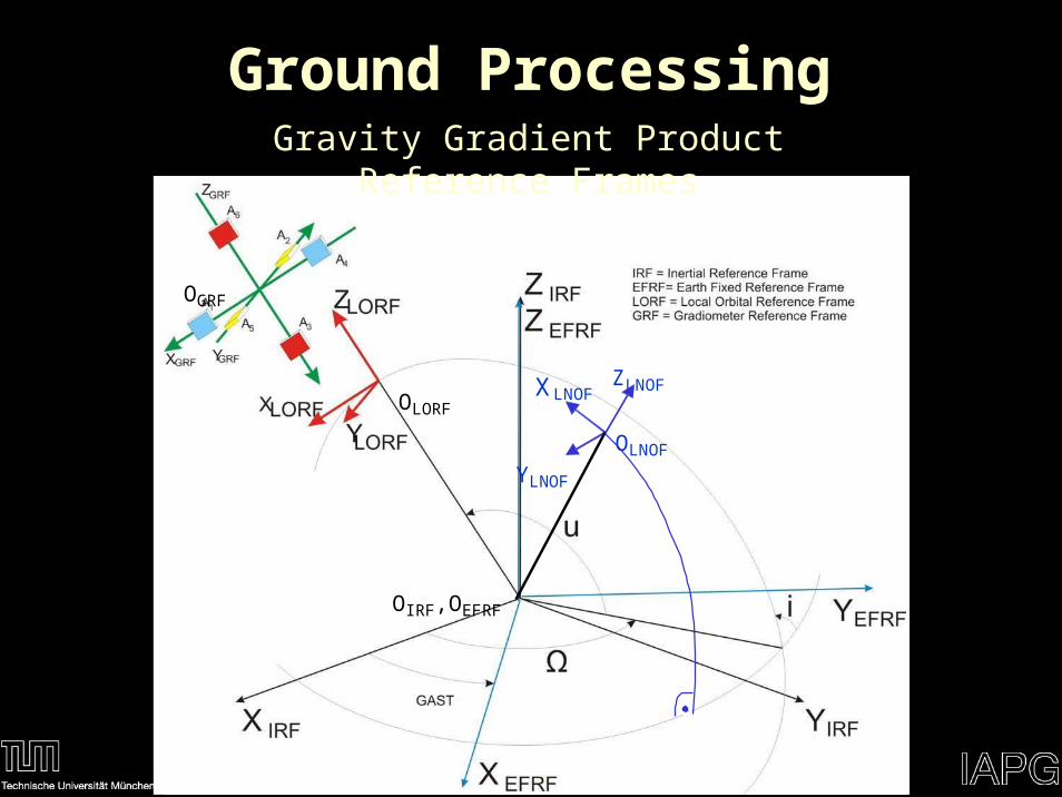
OIRF,OEFRF
OLNOF
ZLNOFXLNOF
YLNOF
Ground ProcessingGravity Gradient Product Reference Frames
OLORF
OGRF
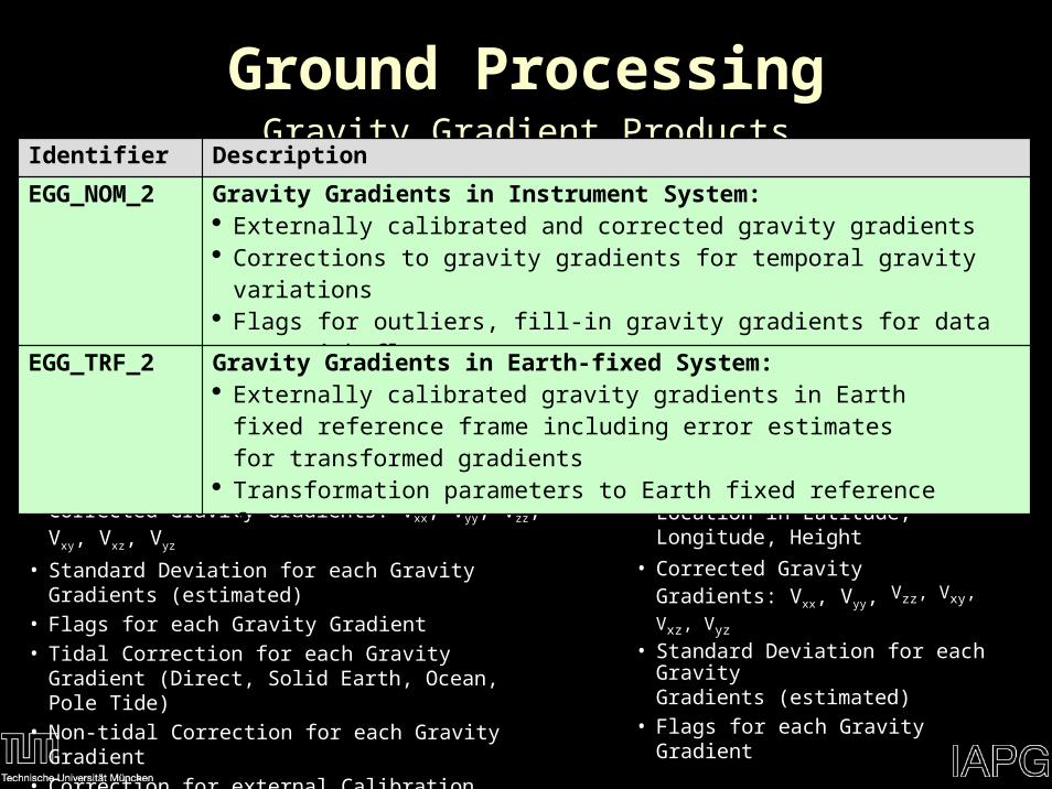
Ground ProcessingGravity Gradient Products
EGG_NOM_2 Data Content:• GPS Time
• Corrected Gravity Gradients: Vxx, Vyy, Vzz, Vxy, Vxz, Vyz
• Standard Deviation for each Gravity Gradients (estimated)• Flags for each Gravity Gradient• Tidal Correction for each Gravity Gradient (Direct, Solid
Earth, Ocean, Pole Tide)• Non-tidal Correction for each Gravity Gradient• Correction for external Calibration• Inertial Attitude Quaternions
EGG_TRF_2 Data Content:• GPS Time• Location in Latitude, Longitude, Height
• Corrected Gravity Gradients: Vxx, Vyy, Vzz, Vxy, Vxz, Vyz
• Standard Deviation for each GravityGradients (estimated)
• Flags for each Gravity Gradient
Identifier Description
EGG_NOM_2 Gravity Gradients in Instrument System: Externally calibrated and corrected gravity gradients Corrections to gravity gradients for temporal gravity variations Flags for outliers, fill-in gravity gradients for data gaps with flags
EGG_TRF_2 Gravity Gradients in Earth-fixed System: Externally calibrated gravity gradients in Earth fixed reference frame
including error estimates for transformed gradients Transformation parameters to Earth fixed reference frame
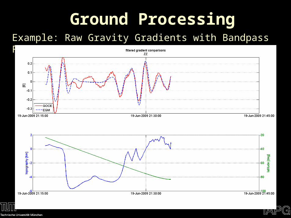
Example: Raw Gravity Gradients with Bandpass Filter applied
Ground Processing
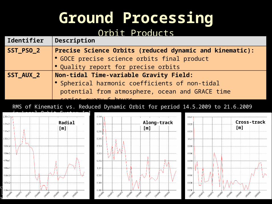
Ground ProcessingOrbit Products
RMS of Kinematic vs. Reduced Dynamic Orbit for period 14.5.2009 to 21.6.2009 in Local Orbit System [m]
Radial [m] Along-track [m] Cross-track [m]
Identifier Description
SST_PSO_2 Precise Science Orbits (reduced dynamic and kinematic): GOCE precise science orbits final product Quality report for precise orbits
SST_AUX_2 Non-tidal Time-variable Gravity Field: Spherical harmonic coefficients of non-tidal potential from atmosphere,
ocean and GRACE time series every 6 hours
Ground ProcessingGravity Field Products
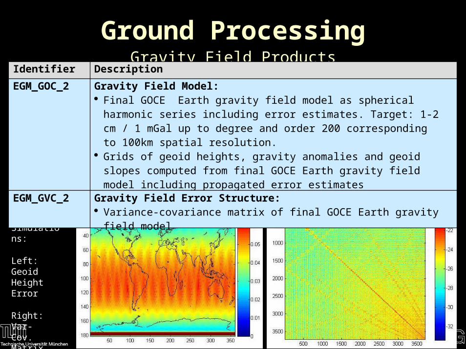
From Simulations:
Left: Geoid Height Error
Right: Var- Cov. Matrix (Subset)
Identifier Description
EGM_GOC_2 Gravity Field Model: Final GOCE Earth gravity field model as spherical harmonic series
including error estimates. Target: 1-2 cm / 1 mGal up to degree and order 200 corresponding to 100km spatial resolution.
Grids of geoid heights, gravity anomalies and geoid slopes computed from final GOCE Earth gravity field model including propagated error estimates
Quality report for final GOCE gravity field model
EGM_GVC_2 Gravity Field Error Structure: Variance-covariance matrix of final GOCE Earth gravity field model
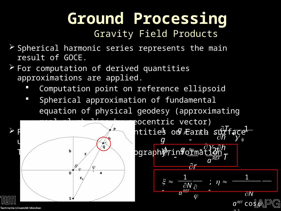
Gravity Field Products Spherical harmonic series represents the main result of GOCE. For computation of derived quantities approximations are applied.
Computation point on reference ellipsoid Spherical approximation of fundamental equation of physical
geodesy (approximating real plumb line by geocentric vector) For computing derived quantities on Earth surface use GOCE User
Toolbox together with topography information.
Ground Processing
r
P
a
b
' O
h
rN
Q
S
0 h 0 h T 1
TPΔ g g
2a REF
Δ g T
r
T
1 N 1
NaREF cos
; a REF
Conclusions GOCE is designed to improve our knowledge of the Earth
gravity field by an order of magnitude.
From the preliminary analyses we are confident to reach this goal after completion of at least two measurement phases.
It is expected that GOCE will open new views in various Earth science disciplines.
The EGG-C consortium is starting to operationally analyze GOCE data during measurement phases.
It is recommended to potential users to take a look to the available products documentation in order to become familiar.