Embed Size (px)
Citation preview
0
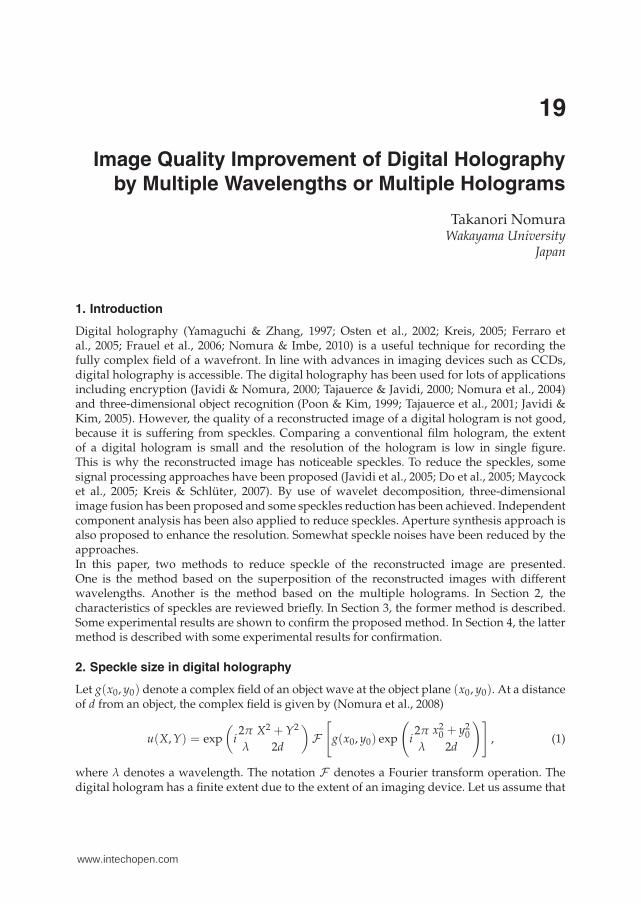
Image Quality Improvement of Digital Holography
by Multiple Wavelengths or Multiple Holograms
Takanori NomuraWakayama University
Japan
1. Introduction
Digital holography (Yamaguchi & Zhang, 1997; Osten et al., 2002; Kreis, 2005; Ferraro etal., 2005; Frauel et al., 2006; Nomura & Imbe, 2010) is a useful technique for recording thefully complex field of a wavefront. In line with advances in imaging devices such as CCDs,digital holography is accessible. The digital holography has been used for lots of applicationsincluding encryption (Javidi & Nomura, 2000; Tajauerce & Javidi, 2000; Nomura et al., 2004)and three-dimensional object recognition (Poon & Kim, 1999; Tajauerce et al., 2001; Javidi &Kim, 2005). However, the quality of a reconstructed image of a digital hologram is not good,because it is suffering from speckles. Comparing a conventional film hologram, the extentof a digital hologram is small and the resolution of the hologram is low in single figure.This is why the reconstructed image has noticeable speckles. To reduce the speckles, somesignal processing approaches have been proposed (Javidi et al., 2005; Do et al., 2005; Maycocket al., 2005; Kreis & Schlüter, 2007). By use of wavelet decomposition, three-dimensionalimage fusion has been proposed and some speckles reduction has been achieved. Independentcomponent analysis has been also applied to reduce speckles. Aperture synthesis approach isalso proposed to enhance the resolution. Somewhat speckle noises have been reduced by theapproaches.In this paper, two methods to reduce speckle of the reconstructed image are presented.One is the method based on the superposition of the reconstructed images with differentwavelengths. Another is the method based on the multiple holograms. In Section 2, thecharacteristics of speckles are reviewed briefly. In Section 3, the former method is described.Some experimental results are shown to confirm the proposed method. In Section 4, the lattermethod is described with some experimental results for confirmation.
2. Speckle size in digital holography
Let g(x0, y0) denote a complex field of an object wave at the object plane (x0, y0). At a distanceof d from an object, the complex field is given by (Nomura et al., 2008)
u(X,Y) = exp
(
i2π
λ
X2 + Y2
2d
)
F
[
g(x0, y0) exp
(
i2π
λ
x20 + y2
0
2d
)]
, (1)
where λ denotes a wavelength. The notation F denotes a Fourier transform operation. Thedigital hologram has a finite extent due to the extent of an imaging device. Let us assume that
19
www.intechopen.com
the extent is a× b. Therefore the digital hologram can be written as
u′(X,Y) = u(X,Y)rect
(
X
a
)
rect
(
Y
b
)
. (2)
The compelx field of the reconstructed object U(x, y) can be calculated by
U(x, y) = exp
(
−i2π
λ
x2 + y2
2d
)
F
[
u′(X,Y) exp
(
−i2π
λ
X2 + Y2
2d
)]
= exp
(
−i2π
λ
x2 + y2
2d
)
{
g(x0, y0) exp
(
i2π
λ
x02 + y2
0
2d
)
∗ sinc( ax0
λd
)
sinc
(
by0
λd
)
}
,
(3)
where the notation ∗ denotes a convolution operation. From Eq. (3), the reconstructed object isgiven by a convolution between the original complex field and a sinc function determined bythe extent of the imaging device. If the speckle size is defined as a full width at half maximumof the main lobe of the sinc function, the size of the speckle ΔSx and ΔSy are approximatelygiven by
ΔSx =λd
a, (4)
ΔSy =λd
b, (5)
respectively. These relations are also shown in the literature (Kreis, 2005). The speckle spoilsthe quality of the reconstructed image. To improve the quality, two approaches are considered.One approach is to make the effect weaken. Another approach is to reduce the size of thespeckle using large a × b based on a synthetic aperture. In the following Sections, bothapproaches are described.
3. Speckles reduction by multiple wavelengths
3.1 Speckle model and reconstructed image with multiple wavelengths
If digital holograms with different wavelengths are recorded, the shape and the positionof speckles are different from each other, because the complex field of the diffracted wavedepends on the wavelength based on Eq. (1). Here it is assumed that the shape and the positionof the speckles are randomly changed in relation to a wavelength. Namely the intensity of thereconstructed object I ′(x, y) is assumed to be given by
I ′(x, y) = I(x, y) + si(x, y), (6)
where I(x, y) and si(x, y) denote the intensity of the reconstructed object without the speckleand the speckle recorded by the wavelengh λi. By the summation of I ′(x, y) over differentwavelengths,
N
∑i=1
I ′(x, y) =N
∑i=1
I(x, y) +N
∑i=1
si(x, y),
NI ′(x, y) = NI(x, y) + S, (7)
398 Holography, Research and Technologies
www.intechopen.com
is obtained, where S is considered as a constant value given by
N
∑i=1
si(x, y) = S. (8)
This equation is based on the above-mentioned assumption. If the constant value S isnegligible smaller than NI ′(x, y), the relation written by
I ′(x, y) = I(x, y), (9)
is can be obtained. Namely, by superposing the multiple reconstructed image intensity withdifferent wavelengths, the blight and dark spots, namely speckles, are smoothed so that theimage quality is improved.However, a difficulty to superpose the reconstructed images is come up. The pixel size Δx andΔy of the reconstructed image are given by
Δx =λd
NXΔX, (10)
Δy =λd
NYΔY, (11)
respectively, where, NX and NY denote the number of pixels of the digital holograms,respectively, and ΔX and ΔY denote the pixels sizes of the imaging devices, respectively(Kreis, 2005; Javidi et al., 2005). The relations mean that the pixel size in the reconstructedimage varies according to the wavelength. The pixel size in the reconstructed image shouldbe equal to superpose. From here the case Δx is explained for simplicity. To equalize Δx, oneof the parameters d, Nx, and ΔX have to be changed. It is unrealistic to change distance daccording to the change of the wavelength, because it is not easy to implement. One approachis to change NX for a different wavelength by padding zeroes (Javidi et al., 2005). This isa simple and smart method, because it needs neither experimental manipulation nor signalprocessing. However the Fast Fourier Transform (FFT) algorithm that the sampling number isequal to the Nth power of two can not be adopted.Here, the method to change the pixel size (sampling interval) of the digital hologram bycompensation is proposed. Let λc and λi (i = 1, . . . , N) denote a criterion wavelength anda wavelength used for recording. Using Eq. (6), the compensated sampling interval Δx′ canbe written as
Δx′ =λi
λcΔx, (12)
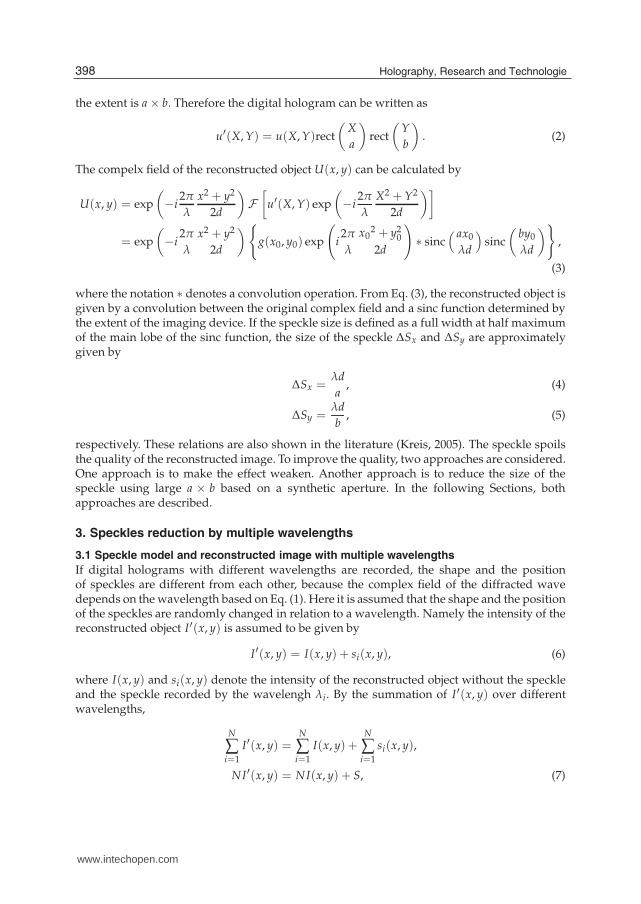
where Δx denote the sampling interval before compensation. Base on the compensation, thepixel value (intensity) of the hologram should be changed. Linear interpolation betweenneighbor pixel values is adopted to determine the value of the compensated pixel. It isassumed here that the the change of the pixel value of the interferogram (digital hologram) isnot sharp. Let I(n) and I ′(m) denote the intensity of the digital hologram at the nth pixel andthe intensity of the compensated digital hologram at the mth pixel, respectively. The schematicdiagram of compensation of a digital hologram for a different wavelength is shown in Fig. 1.The compensated pixel value denoted by I ′(m + 1) is given by
I ′(m + 1) =I(n + 1) − I(n)
Δx
{
(m + 1)Δx′ − nΔx}
+ I(n). (13)
399Image Quality Improvement of Digital Holography by Multiple Wavelengths or Multiple Holograms
www.intechopen.com
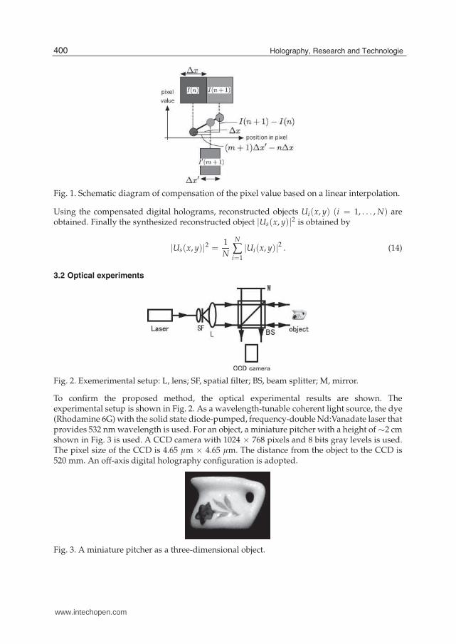
Fig. 1. Schematic diagram of compensation of the pixel value based on a linear interpolation.
Using the compensated digital holograms, reconstructed objects Ui(x, y) (i = 1, . . . , N) areobtained. Finally the synthesized reconstructed object |Us(x, y)|2 is obtained by
|Us(x, y)|2 =1
N
N
∑i=1
|Ui(x, y)|2 . (14)
3.2 Optical experiments
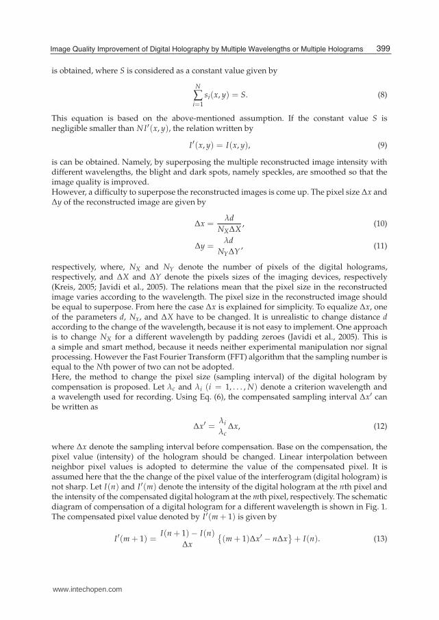
Fig. 2. Exemerimental setup: L, lens; SF, spatial filter; BS, beam splitter; M, mirror.
To confirm the proposed method, the optical experimental results are shown. Theexperimental setup is shown in Fig. 2. As a wavelength-tunable coherent light source, the dye(Rhodamine 6G) with the solid state diode-pumped, frequency-double Nd:Vanadate laser thatprovides 532 nm wavelength is used. For an object, a miniature pitcher with a height of ∼2 cmshown in Fig. 3 is used. A CCD camera with 1024 × 768 pixels and 8 bits gray levels is used.The pixel size of the CCD is 4.65 μm × 4.65 μm. The distance from the object to the CCD is520 mm. An off-axis digital holography configuration is adopted.
Fig. 3. A miniature pitcher as a three-dimensional object.
400 Holography, Research and Technologies
www.intechopen.com
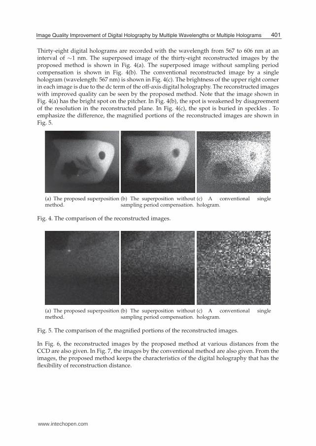
Thirty-eight digital holograms are recorded with the wavelength from 567 to 606 nm at aninterval of ∼1 nm. The superposed image of the thirty-eight reconstructed images by theproposed method is shown in Fig. 4(a). The superposed image without sampling periodcompensation is shown in Fig. 4(b). The conventional reconstructed image by a singlehologram (wavelength: 567 nm) is shown in Fig. 4(c). The brightness of the upper right cornerin each image is due to the dc term of the off-axis digital holography. The reconstructed imageswith improved quality can be seen by the proposed method. Note that the image shown inFig. 4(a) has the bright spot on the pitcher. In Fig. 4(b), the spot is weakened by disagreementof the resolution in the reconstructed plane. In Fig. 4(c), the spot is buried in speckles . Toemphasize the difference, the magnified portions of the reconstructed images are shown inFig. 5.
(a) The proposed superpositionmethod.
(b) The superposition withoutsampling period compensation.
(c) A conventional singlehologram.
Fig. 4. The comparison of the reconstructed images.
(a) The proposed superpositionmethod.
(b) The superposition withoutsampling period compensation.
(c) A conventional singlehologram.
Fig. 5. The comparison of the magnified portions of the reconstructed images.
In Fig. 6, the reconstructed images by the proposed method at various distances from theCCD are also given. In Fig. 7, the images by the conventional method are also given. From theimages, the proposed method keeps the characteristics of the digital holography that has theflexibility of reconstruction distance.
401Image Quality Improvement of Digital Holography by Multiple Wavelengths or Multiple Holograms
www.intechopen.com
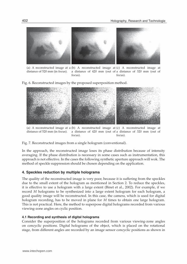
(a) A reconstructed image at adistance of 520 mm (in focus).
(b) A reconstructed image ata distance of 420 mm (out offocus).
(c) A reconstructed image ata distance of 320 mm (out offocus).
Fig. 6. Reconstructed images by the proposed superposition method.
(a) A reconstructed image at adistance of 520 mm (in focus).
(b) A reconstructed image ata distance of 420 mm (out offocus).
(c) A reconstructed image ata distance of 320 mm (out offocus).
Fig. 7. Reconstructed images from a single hologram (conventional).
In the approach, the reconstructed image loses its phase distribution because of intensityaveraging. If the phase distribution is necessary in some cases such as instrumentation, thisapproach is not effective. In the cases the following synthetic aperture approach will wok. Themethod of speckle suppression should be chosen depending on the application.
4. Speckles reduction by multiple holograms
The quality of the reconstructed image is very poor, because it is suffering from the specklesdue to the small extent of the hologram as mentioned in Section 2. To reduce the speckles,it is effective to use a hologram with a large extent (Binet et al., 2002). For example, if werecord M holograms to be synthesized into a large extent hologram for each hologram, agood quality image will be reconstructed. In this case, the camera, which is used for digitalhologram recording, has to be moved in plane for M times to obtain one large hologram.This is not practical. Here, the method to superpose digital holograms recorded from variousviewing-zone angles on cyclic position.
4.1 Recording and synthesis of digital holograms
Consider the superposition of the holograms recorded from various viewing-zone angleson concyclic positions. Digital holograms of the object, which is placed on the rotationalstage, from different angles are recorded by an image sensor concyclic positions as shown in
402 Holography, Research and Technologies
www.intechopen.com
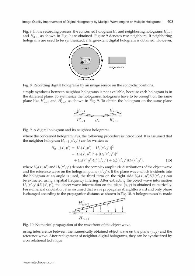
Fig. 8. In the recording process, the concerned hologram Hn and neighboring holograms Hn−1
and Hn+1 as shown in Fig. 9 are obtained. Figure 9 denotes two neighbors. If neighboringholograms are used to be synthesized, a large-extent digital hologram is obtained. However,
Fig. 8. Recording digital holograms by an image sensor on the concyclic positions.
simply synthesis between neighbor holograms is not available, because each hologram is inthe different plane. To synthesize the holograms, holograms have to be brought on the sameplane like H′
n−1 and H′n+1 as shown in Fig. 9. To obtain the hologram on the same plane
Fig. 9. A digital hologram and its neighbor holograms.
where the concerned hologram lays, the following procedure is introduced. It is assumed thatthe neighbor hologram Hn−1(x
′, y′) can be written as
Hn−1(x′, y′) = |Ur(x
′, y′) +Uo(x′, y′)|2
= |Ur(x′, y′)|2 + |Uo(x
′, y′)|2
+Uo(x′, y′)U∗
r (x′, y′) +U∗o (x′, y′)Ur(x
′, y′), (15)
where Uo(x′, y′) and Ur(x′, y′) denotes the complex amplitude distributions of the object waveand the reference wave on the hologram plane (x′, y′). If the plane wave which incidents intothe hologram at an angle is used, the third term on the right side Uo(x′, y′)U∗
r (x′, y′) canbe extracted using a spatial frequency filtering. After extracting the object wave informationUo(x′, y′)U∗
r (x′, y′), the object wave information on the plane (x, y) is obtained numerically.For numerical calculation, it is assumed that wave propagates straightforward and only phaseis changed according to the propagation distance as shown in Fig. 10. A hologram can be made
Fig. 10. Numerical propagation of the wavefront of the object wave.
using interference between the numerically obtained object wave on the plane (x, y) and thereference wave. After realignment of neighbor digital holograms, they can be synthesized bya correlational technique.
403Image Quality Improvement of Digital Holography by Multiple Wavelengths or Multiple Holograms
www.intechopen.com
4.2 Experimental results
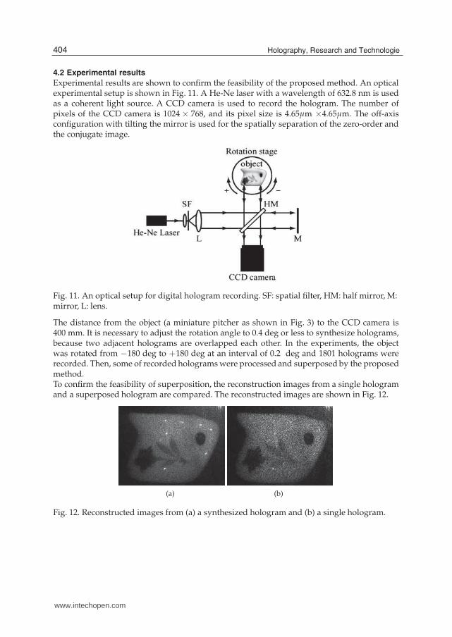
Experimental results are shown to confirm the feasibility of the proposed method. An opticalexperimental setup is shown in Fig. 11. A He-Ne laser with a wavelength of 632.8 nm is usedas a coherent light source. A CCD camera is used to record the hologram. The number ofpixels of the CCD camera is 1024 × 768, and its pixel size is 4.65μm ×4.65μm. The off-axisconfiguration with tilting the mirror is used for the spatially separation of the zero-order andthe conjugate image.
Fig. 11. An optical setup for digital hologram recording. SF: spatial filter, HM: half mirror, M:mirror, L: lens.
The distance from the object (a miniature pitcher as shown in Fig. 3) to the CCD camera is400 mm. It is necessary to adjust the rotation angle to 0.4 deg or less to synthesize holograms,because two adjacent holograms are overlapped each other. In the experiments, the objectwas rotated from −180 deg to +180 deg at an interval of 0.2 deg and 1801 holograms wererecorded. Then, some of recorded holograms were processed and superposed by the proposedmethod.To confirm the feasibility of superposition, the reconstruction images from a single hologramand a superposed hologram are compared. The reconstructed images are shown in Fig. 12.
(a) (b)
Fig. 12. Reconstructed images from (a) a synthesized hologram and (b) a single hologram.
404 Holography, Research and Technologies
www.intechopen.com
(a) (b)
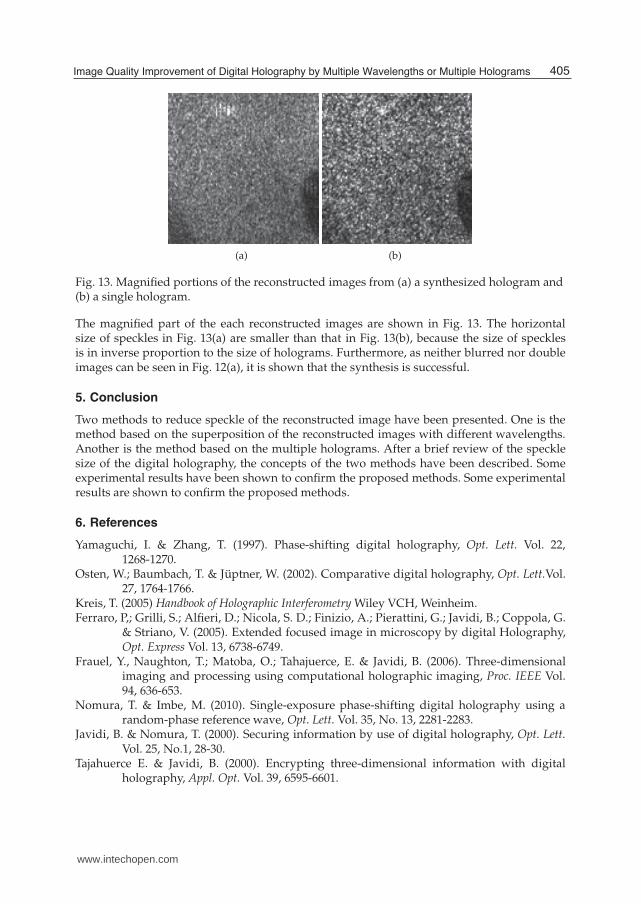
Fig. 13. Magnified portions of the reconstructed images from (a) a synthesized hologram and(b) a single hologram.
The magnified part of the each reconstructed images are shown in Fig. 13. The horizontalsize of speckles in Fig. 13(a) are smaller than that in Fig. 13(b), because the size of specklesis in inverse proportion to the size of holograms. Furthermore, as neither blurred nor doubleimages can be seen in Fig. 12(a), it is shown that the synthesis is successful.
5. Conclusion
Two methods to reduce speckle of the reconstructed image have been presented. One is themethod based on the superposition of the reconstructed images with different wavelengths.Another is the method based on the multiple holograms. After a brief review of the specklesize of the digital holography, the concepts of the two methods have been described. Someexperimental results have been shown to confirm the proposed methods. Some experimentalresults are shown to confirm the proposed methods.
6. References
Yamaguchi, I. & Zhang, T. (1997). Phase-shifting digital holography, Opt. Lett. Vol. 22,1268-1270.
Osten, W.; Baumbach, T. & Jüptner, W. (2002). Comparative digital holography, Opt. Lett.Vol.27, 1764-1766.
Kreis, T. (2005) Handbook of Holographic Interferometry Wiley VCH, Weinheim.Ferraro, P,; Grilli, S.; Alfieri, D.; Nicola, S. D.; Finizio, A.; Pierattini, G.; Javidi, B.; Coppola, G.
& Striano, V. (2005). Extended focused image in microscopy by digital Holography,Opt. Express Vol. 13, 6738-6749.
Frauel, Y., Naughton, T.; Matoba, O.; Tahajuerce, E. & Javidi, B. (2006). Three-dimensionalimaging and processing using computational holographic imaging, Proc. IEEE Vol.94, 636-653.
Nomura, T. & Imbe, M. (2010). Single-exposure phase-shifting digital holography using arandom-phase reference wave, Opt. Lett. Vol. 35, No. 13, 2281-2283.
Javidi, B. & Nomura, T. (2000). Securing information by use of digital holography, Opt. Lett.Vol. 25, No.1, 28-30.
Tajahuerce E. & Javidi, B. (2000). Encrypting three-dimensional information with digitalholography, Appl. Opt. Vol. 39, 6595-6601.
405Image Quality Improvement of Digital Holography by Multiple Wavelengths or Multiple Holograms
www.intechopen.com
Nomura, T.; Uota, K. & Morimoto, Y. (2004). Hybrid optical encryption of a 3-D object using adigital holographic technique, Opt. Eng. Vol. 43, 2228-2232.
Poon, T.-C. & Kim, T. (1999). Optical Image Recognition of Three-Dimensional Objects, Appl.Opt. Vol. 38, 370-381.
Tajahuerce, E.; Matoba, O. & Javidi, B. (2001). Shift-invariant three-dimensional objectrecognition by means of digital holography, Appl. Opt. Vol. 40, 3877-3888.
Javidi, B. & Kim, D. (2005). Three-dimensional-object recognition by use of single-exposureon-axis digital holography, Opt. Lett. Vol. 30, 236-238.
Javidi,B.; Ferraro, P.; Hong, S.-H.;De Nicola, S.; Finizio, A; Alfieri, D. & Pierattini, G. (2005)Three-dimensional image fusion by use of multiwavelength digital holography, Opt.Lett. Vol. 30, 144-146.
Do, C. M.; Hong, S.-H.; Nomura, T. & Javidi, B. (2005) Multi-wavelength holographic imagefusions using discrete wavelet transform, Proc. SPIE Vol. 6016, 60160Z-1-6.
Maycock, J.; Mc Elhinney, C. P.; McDonald, J. B.; Naughton, T. & Javidi, B. (2005). Independentcomponent analysis applied to digital holograms of three-dimensional objects, Proc.SPIE Vol. 5908, 590806-1-9.
Kreis, T. & Schlüter, K. (2007). Resolution enhancement by aperture synthesis in digitalholography, Opt. Eng. Vol. 46, 055803.
Nomura, T., Okamura, M., Nitanai, E. & Numata, T. (2008). Image quality improvement ofdigital holography by superposition of reconstructed images obtained by multiplewavelengths, Appl. Opt. Vol. 47, No. 19, D38-D43.
Binet, R.; Colineau, J. & Lehureau, J. -C. (2002). Short-range synthetic aperture imaging at 633nm by digital holography, Appl. Opt. Vol. 41, 4775-4782.
406 Holography, Research and Technologies
www.intechopen.com
Holography, Research and TechnologiesEdited by Prof. Joseph Rosen
ISBN 978-953-307-227-2Hard cover, 454 pagesPublisher InTechPublished online 28, February, 2011Published in print edition February, 2011
InTech EuropeUniversity Campus STeP Ri Slavka Krautzeka 83/A 51000 Rijeka, Croatia Phone: +385 (51) 770 447 Fax: +385 (51) 686 166www.intechopen.com
InTech ChinaUnit 405, Office Block, Hotel Equatorial Shanghai No.65, Yan An Road (West), Shanghai, 200040, China
Phone: +86-21-62489820 Fax: +86-21-62489821
Holography has recently become a field of much interest because of the many new applications implementedby various holographic techniques. This book is a collection of 22 excellent chapters written by various experts,and it covers various aspects of holography. The chapters of the book are organized in six sections, startingwith theory, continuing with materials, techniques, applications as well as digital algorithms, and finally endingwith non-optical holograms. The book contains recent outputs from researches belonging to different researchgroups worldwide, providing a rich diversity of approaches to the topic of holography.
How to referenceIn order to correctly reference this scholarly work, feel free to copy and paste the following:
Takanori Nomura (2011). Image Quality Improvement of Digital Holography by Multiple Wavelengths orMultiple Holograms, Holography, Research and Technologies, Prof. Joseph Rosen (Ed.), ISBN: 978-953-307-227-2, InTech, Available from: http://www.intechopen.com/books/holography-research-and-technologies/image-quality-improvement-of-digital-holography-by-multiple-wavelengths-or-multiple-holograms

© 2011 The Author(s). Licensee IntechOpen. This chapter is distributedunder the terms of the Creative Commons Attribution-NonCommercial-ShareAlike-3.0 License, which permits use, distribution and reproduction fornon-commercial purposes, provided the original is properly cited andderivative works building on this content are distributed under the samelicense.