Embed Size (px)
Citation preview
Journal
Paper
Background
Impala Platinum Ltd. has embarked on anexpansion programme to grow platinumproduction from 1.9 million ounces (moz) perannum to 2.8 moz by December 2008. Part ofthe expansion involves increasing smeltercapacity by approximately 50%.
A significant portion (40%) of the R 850million that has been appropriated for thesmelter expansion will be for off-gas cleaningand treatment facilities. Due to increasingpressure from authorities and the promul-gation of the new Air Quality Act it hasbecome necessary for Impala Platinum tofurther address air quality issues. The smelteremission control strategy is based on threeimportant aspects, which must be adequatelyaddressed in order to improve the quality ofambient air, in and around the plant. The firstaspect is to meet the ambient air qualitystandards as specified in the Air Quality Act.The second criterion is to improve the visualaspect of the plant so that good publicrelations are fostered, and the third is tominimize occupational exposure of employeesto dust and sulphur dioxide gas so thatoccupational hygiene is improved.
It was decided early on that to address allthree legs of the strategy, a full feasibilitystudy would be carried out on two off-gascleaning routes. The route selected would haveto meet the above objectives at the increasedproduction rate, but in addition, improve animportant parameter, which is the amount ofSO2 emitted per ounce of platinum produced.This parameter is currently 5.8 kg SO2 perplatinum ounce but will reduce to approxi-mately 2.1 kg SO2 per platinum ounce after the implementation of the future gas cleaningexpansion. Despite the increased platinumproduction, this represents an improvement of 65%.
The first option study (option 1) wasawarded to IST Industrial in collaboration withMECS and essentially entails an expansion ofthe existing gas cleaning infrastructure withtwo new lime scrubbing plants for the tailgases and fugitive gases. The second optionstudy (option 2) was awarded to E+PC incollaboration with Outokumpu and is acompletely new wet gas treatment section anddouble conversion, double catalysis acid plantwith a sulphur burner, which treats all gasesexcept for furnace fugitive gases. Furnacefugitive gases will be treated in the existingSulfacidTM plant. Each option is described inmore detail below.
➤ Option 1—Upgraded and expandedexisting acid plant, expanded existingSulfacidTM plant, tail gas scrubbing in anew lime scrubbing plant and fugitivegas capture and treatment in a secondnew lime scrubbing plant. The existing sulphuric acid plant isupgraded from a capacity of 12 Nm3/s to15 Nm3/s and treats converter off-gas
Impala Platinum Smelter, Rustenburg—an integrated smelter off-gas treatmentsolution
by G. Westcott*, M. Tacke†, N. Schoeman§, and N. Morgan§
Synopsis
Impala Platinum, the second largest platinum producer in the world,is embarking on a major expansion strategy to increase its platinumoutput from 1.95 moz to 2.8 moz by the year 2008. The smeltercomplex, situated in Rustenburg, will undergo substantial modifi-cations, and will require a solution to the capture and treatment ofthe smelter off-gases and dust produced during smelting andconverting operations. One of the solutions explored was anintegrated approach, where all the off-gases from both the primarysmelting electric furnaces and the converter operations are routed toa large central gas cleaning and double catalysis, double absorptionacid plant. In-line sulphur burning, utilizing a highly flexible LURO1
spin cup burner with a turn down ratio of 50%, ensures that theacid plant operates independently of operating conditions at thesmelter complex.
* Impala Platinum.† Outotec.§ Engineering and Projects Company.© The Southern African Institute of Mining and
Metallurgy, 2007. SA ISSN 0038–223X/3.00 +0.00. This paper was first published at the SAIMMConference, SO2 handling and sulphuric acidmanufacture, 18–20 April 2007
281The Journal of The Southern African Institute of Mining and Metallurgy VOLUME 107 NON-REFEREED PAPER MAY 2007 ▲
Impala Platinum Smelter, Rustenburg—an integrated smelter off-gas treatment
only. The existing Sulfacid™ plant is upgraded from 8to 12 pots and treats off-gas from the three operationalfurnaces. The tail gases from the expanded acid andSulfacid™ plants are combined and treated in a newlime scrubbing plant, which produces gypsum. Thecleaned tail gas from this plant is vented to atmospherevia a new stack. Fugitive gases from the converters andfurnaces are captured and treated in a new limescrubbing plant. The tail gas from this plant is ventedto atmosphere via a new stack.
➤ Option 2—New gas cleaning section and doubleconversion, double catalysis sulphuric acid plant withsulphur burner.A new double conversion, double catalysis sulphuricacid plant with sulphur burner of 44 Nm3/s capacity isbuilt for the treatment of converter primary and fugitivegas and furnace primary off-gas. The cleaned gas isvented to atmosphere via a new stack. The existingSulfacid™ plant is utilized for the treatment of furnacefugitive gases. The cleaned gas is vented to the existingSulfacid™ stack.
Introduction
In all pyrometallurgical processes, vapours develop over theliquid slag/metal phase or on the surface of the solid particlesunder high temperature conditions. These vapours containreaction products of the slag or metal phase with the gasphase and/or simply products of evaporation formed due tothe extremely elevated temperatures. The solid and vapourcontents in the gas may have to be removed for the followingreasons:
➤ The removal of hazardous components for environ-mental protection
➤ The recovery of valuable contents from the gas phase.
Engineering and Projects Company and OutokumpuTechnology undertook a detailed study for the ImpalaPlatinum Smelter, evaluating the treatment of the entiresmelter complex off-gases through a single large gas cleaningand acid plant. This included both the constant volume, lowSO2 content electric furnace off-gases and the highly variablevolume and variable SO2 content converter off-gases.
The brief was to ensure world-class standards in terms ofparticulate capture and SO2 emissions. A double catalysis,double absorption plant was designed incorporating sulphurburning to supplement the thermal requirements for auto-thermal operation. The resultant design met all the particulateremoval criteria and would have resulted in no visible stackemissions with all discharges well within the applicableenvironmental legislation. The discussion below refers to theproposal made for treating these off-gases.
Impala Platinum currently operates two 6-in-line electricfurnaces for the smelting of platinum concentrate at itsRustenburg smelter. As part of Impala’s expansionprogramme, a third electric furnace will be brought on line in2008. The continuous off-gas flow from all three of thesefurnaces contains:
➤ Considerable quantities of dust➤ SO2 generated by sulphide combustion
➤ SO3 generated by sulphide combustion➤ Metalloids contents such as As, Se and other
evaporated traces➤ Halogens such as HF and HCl.
Dust was to be recovered mainly for the PGM content, butis also associated with other impurities in the gaseous phase.The separation of solid particles is primarily done in the hotgas precipitators, leaving the other impurities as vapours inthe gas phase.
The gases are collected from the furnaces and ductedunder suction to hot gas electrostatic precipitators. Theproposed option was to then pass these gases to a scrubbing,cleaning and cooling section prior to entering doubleabsorption sulphur burning acid plant for the conversion ofSO2 and the absorption of SO3.
There are also 6 Pierce-Smith converters, which are usedto oxidize the furnace matte. These provide another majorsource of discontinuous gas flow with large fluctuations. Twoof these are large converters of 77 m3 capacity and four aresmaller converters of 33 m3 capacity. Another large converterwill be brought into operation during the expansionprogramme. The operation of the Peirce-Smith converters willbe cyclical and the sequence will be dependent upon matteproduction in the electric furnaces. Due to the cyclic nature ofthe converting operation, the SO2 strength of the convertergas feed to the acid plant will vary. A sulphur burning sectionis incorporated into the proposal in order to stabilize theamount and strength of the SO2 gas and provide for steadyand reliable operation.
Before the gas enters the acid plant, it is important thatthe majority of the impurities are removed as these can becontaminants and lead to the production of sub-standardproduct acid. Impurities in the product acid are of particularconcern where the acid will be used in the production offertilizers. Contaminants also cause blinding of the catalystbed and excessive pressure differential through the system. Itis also important that the gas is cooled to the correcttemperature so that the water balance is optimal and so thatexcessive water is not introduced into the system.
This paper describes the unique solution of treating thecombined converter and furnace off-gases, supplementedwith sulphur burning to ensure strike temperature ismaintained for optimum catalytic conversion of SO2 to SO3.The importance of a sequential methodology for cleaning theoff-gases from the furnace and converter operations is alsodetailed.
Each stage of cleaning has its own unique characteristicsand equipment selection is important for optimal cleaningoperations.
Auto-thermal converter operation
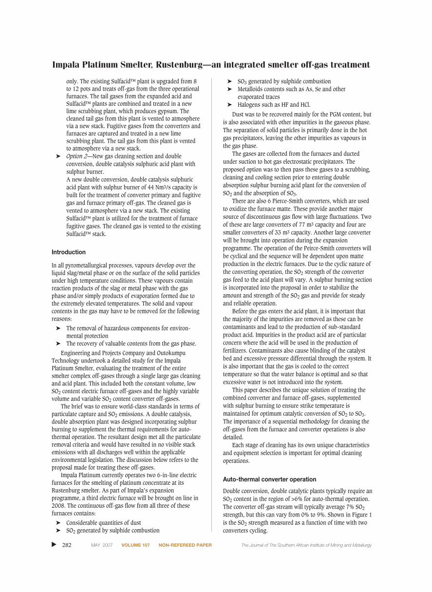
Double conversion, double catalytic plants typically require anSO2 content in the region of >6% for auto-thermal operation.The converter off-gas stream will typically average 7% SO2
strength, but this can vary from 0% to 9%. Shown in Figure 1is the SO2 strength measured as a function of time with twoconverters cycling.
▲
282 MAY 2007 VOLUME 107 NON-REFEREED PAPER The Journal of The Southern African Institute of Mining and Metallurgy
The introduction of the proprietary spin cup burner allowsrapid ramp-up and turn-down of the SO2 content from thesulphur burner. As can be seen in Figure 1, the SO2 off-gasconcentration can vary considerably with the cycling of thePierce-Smith converters. In order to keep the plant in auto-thermal operation at relatively constant temperatures,approximately 59 tons of sulphur must be burnt each day.This results in an additional 170 tons per day of 98.5% acidproduction.
Furnace off-gas collection, electrostatic precipitationand scrubbing
Off-gases from the electric furnaces will be treated separatelyfrom the converter off-gases through hot ESPs and a wetventuri scrubber before being combined at the primary starcooler outlet.
The primary reason for the separate treatment of gasesfrom the furnaces and converters, is to ensure the recapture ofdry, entrained dust in the furnace gas. Due to the removal ofthe furnace gases under suction, dust from the furnace blacktop is carried towards the gas treatment section (Table I). Asthis dust originates from the concentrate feedstock to thefurnace, it contains substantial valuable elements and it ispreferable to recover the material prior to wet treatment sothat it can be returned to the furnace concentrate silos as adry feed.
The off-gas from the three electric furnaces will be ductedto two new hot gas electrostatic precipitators for the removalof solid dust particles. Each precipitator will have 4 fieldswhere 3 fields of one hot gas ESP will give the requiredcleaning efficiency. This ensures that the second ESP is ableto give standby capacity for maintenance periods. It is of
Impala Platinum Smelter, Rustenburg—an integrated smelter off-gas treatmentJournal
Paper
283The Journal of The Southern African Institute of Mining and Metallurgy VOLUME 107 NON-REFEREED PAPER MAY 2007 ▲
Figure 1—SO2 gas strength versus converter cycle time
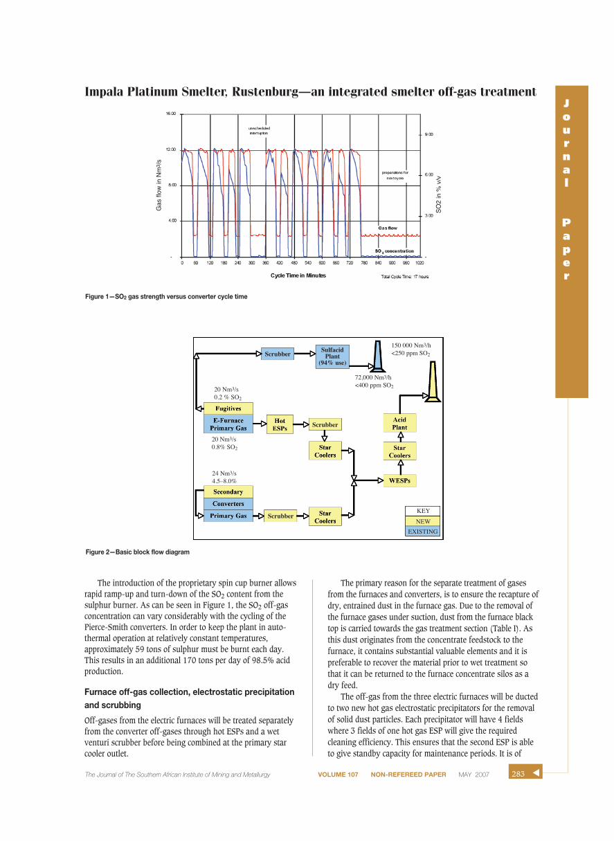
Figure 2—Basic block flow diagram
20 Nm3/s0.8% SO2
20 Nm3/s0.2 % SO2
Scrubber
Scrubber
Scrubber
KEY
NEW
EXISTING
SulfacidPlant
(94% use)
150 000 Nm3/h<250 ppm SO2
72,000 Nm3/h<400 ppm SO2
24 Nm3/s4.5–8.0%
Gas
flow
in N
m3 /
s
SO
2 in
% v
/v
Impala Platinum Smelter, Rustenburg—an integrated smelter off-gas treatment
extreme importance that the temperature of the gas be keptabove 300°C as this ensures that the gas remains above itsdew point and that there is no condensation and consequentcorrosion of the precipitator shell and internals. Despite therequirement for excess capacity in the hot ESPs, it isimportant that the vessels are not vastly overdesigned as thiswill result in a large drop in gas velocity from the inlet ductinto the vessel and a large resultant cooling of the gas incontact with the outer casing of the ESP. This would increasethe risk of cooling this gas below its dew point and thelikelihood of casing corrosion would be increased, asobserved frequently in past operations.
The off-gas will be drawn from the electric furnaces andthrough the hot gas precipitators by the furnace ID fans, andducted to the primary off-gas scrubbing plant. In the hot gaselectrostatic precipitators, the dust load in the off-gas will bereduced from 65 000 mg/Nm3 to less than 30 mg/Nm3.
Most dust particles in the off-gas such as Si, Cu, Zn, Feand Pb are removed. The dust collected in the hot gas precip-itator hoppers will be pneumatically conveyed to existingconcentrate silos. The temperature of the off-gas entering thehot gas ESPs should be kept above 300°C so that the traces ofSO3 in the gas do not drop below the dew point and formcorrosive sulphuric acid.
Larger solid particles are removed in the hot gas ESPs,but the fine particles, volatilized metalloids and other gaseouscompounds require further wet gas cleaning for removal. Theelectric furnace off-gas leaving the ID fans will be ducted tothe venturi scrubber, where the gas will be cooled by contactwith a dilute sulphuric acid spray. The cooled gas leaving theventuri scrubber will pass through a droplet eliminator,before entering the gas cooling stage. Process water will beadded to the venturi scrubber circuit to make up the lossesdue to evaporation and the bleed to the converter gas radialflow scrubber circuit. During the scrubbing process, vapoursof SO3, As and Se as well as other metal vapours will betransformed into submicron particles to be removed in thedownstream wet ESPs (WESPs).
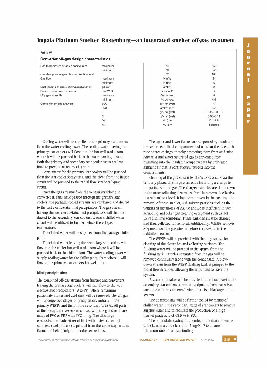
Pierce-Smith converter gas collection and scrubbingThe combined Pierce-Smith converter off-gas stream (TableIII), collected by the converter primary and secondary hoods,will be received at a terminal point in the converter off-gasduct, and ducted to the new converter off-gas primary gasscrubbing plant. As the converter off-gas does not containthe levels of dust evident in the furnace off-gas, it will not benecessary to pass this gas through hot gas ESPs.
The converter off-gas will be ducted directly to the highefficiency (radial flow) scrubber, where the gas will be cooledand partially cleaned by contact with a dilute sulphuric acidstream. The cooled gas leaving the scrubber will pass throughthe droplet eliminator. Dissolved impurities in the converteroff-gas are collected in a similar manner to the impuritiesremoved from the furnace off-gas in the venturi scrubber.The variable throat of the radial flow scrubber ensures thatthere is a constant scrubbing efficiency and constant pressuredrop with the varying gas volume through the system as the
converter blow cycle continues.There is a brick lining at the dry/wet interface in both the
venturi and high efficiency scrubbers. This lining resistsabrasion as well as chemical attack by fluorine.
The converter ID fans will draw the off-gases from theconverters and through the radial flow scrubber. The level ofsuspended solids in the scrubber liquor circuit will becontrolled at an acceptable level by pumping a side stream tothe settler. The collected solids will be drained from the settlerand recycled to the smelter.
The bleed out of the scrubber circuit will be pumped tothe stripping tower, where the dissolved SO2 will be strippedout by air drawn in under suction and the SO2 gas returnedto the main off-gas stream. The stripped weak acid bleedstream will be combined with the underflow from the settlerand recycled to the Smelter.
Gas gooling
The off-gas streams leaving the furnace venturi scrubber andthe converter ID fans will be ducted to the primary starcoolers as independent streams as the gas volume of theconverter off-gas stream will vary. The gas cooling isnecessary to achieve the correct gas temperature to meet thewater balance requirements in the acid plant as well ascooling the gas to substantially assist the removal of halidesfrom the gas stream. If halides such as Cl- and F- are notefficiently removed from the system, they are detrimental toproduct acid quality as well as possibly causing problemswith corrosion to acid piping and coolers, deterioration ofcandle filters and the destruction of the catalyst carrier.
▲
284 MAY 2007 VOLUME 107 NON-REFEREED PAPER The Journal of The Southern African Institute of Mining and Metallurgy
Table I
Furnace off-gas design characteristics
Off-gas temperature maximum °C 400minimum °C 300
Maximum flow Nm3/s 18Pressure mbar g -20Dust burden: maximum (dry) g/Nm3 65Analysis: SO2 (normal—in a wet basis) % v/v 0.9
(maximum—in a wet basis) % v/v 1.1SO3 g/Nm3 (wet) 3.5H2O g/Nm3 (dry) 20O2 % (wet) 19Cl- mg/Nm3 4.3F- mg/Nm3 121.8
Table II
Analysis of dust collected at current ESPs
Element Design value (%)
Silica 43.0Magnesium oxides 18.0Alumina 12.0Sulphides 4.50Calcium oxides 3.50
Cooling water will be supplied to the primary star coolersfrom the water cooling tower. The cooling water leaving theprimary star coolers will flow into the hot well tank, fromwhere it will be pumped back to the water cooling tower.Both the primary and secondary star cooler tubes are leadlined to prevent attack by Cl- and F-.
Spray water for the primary star coolers will be pumpedfrom the star cooler spray tank, and the bleed from the liquorcircuit will be pumped to the radial flow scrubber liquorcircuit.
Once the gas streams from the venturi scrubber andconverter ID fans have passed through the primary starcoolers, the partially cooled streams are combined and ductedto the wet electrostatic mist precipitators. The gas streamleaving the wet electrostatic mist precipitators will then beducted to the secondary star coolers, where a chilled watercircuit will be utilized to further reduce the off-gastemperature.
The chilled water will be supplied from the package chillerplant.
The chilled water leaving the secondary star coolers willflow into the chiller hot well tank, from where it will bepumped back to the chiller plant. The water cooling tower willsupply cooling water for the chiller plant, from where it willflow to the primary star coolers hot well tank.
Mist precipitation
The combined off-gas stream from furnace and convertersleaving the primary star coolers will then flow to the wetelectrostatic precipitators (WESPs), where remainingparticulate matter and acid mist will be removed. The off-gaswill undergo two stages of precipitation, initially in theprimary WESPs and then in the secondary WESPs. All partsof the precipitator vessels in contact with the gas stream aremade of PVC or FRP with PVC lining. The dischargeelectrodes are made either of lead with a steel core or ofstainless steel and are suspended from the upper support andframe and held firmly in the tube centre lines.
The upper and lower frames are supported by insulatorshoused in lead-lined compartments situated at the side of theprecipitator casings, thereby protecting them from acid mist.Any mist and water saturated gas is prevented frommigrating into the insulator compartments by preheatedambient air that is continuously purged into thecompartments.
Cleaning of the gas stream by the WESPs occurs via thecentrally placed discharge electrodes imparting a charge tothe particles in the gas. The charged particles are then drawnto the outer collecting electrodes. Particle removal is effectiveto a sub-micron level. It has been proven in the past that theremoval of these smaller, sub-micron particles such as thevolatilized metalloids of As, Te and Be is inefficient in wetscrubbing and other gas cleaning equipment such as hotESPs and lime scrubbing. These particles must be chargedand then collected for removal. Additionally, WESPs removeSO3 mist from the gas stream before it moves on to theoxidation section.
The WESPs will be provided with flushing sprays forcleaning of the electrodes and collecting surfaces. Theflushing water will be pumped to the sprays from theflushing tank. Particles separated from the gas will beremoved continually along with the condensate. A blow-down stream from the WESP flushing tank is pumped to theradial flow scrubber, allowing the impurities to leave thesystem.
A vacuum breaker will be provided in the duct leaving thesecondary star coolers to protect equipment from excessivesuction conditions observed when there is a blockage in thesystem.
The demisted gas will be further cooled by means ofchilled water in the secondary stage of star coolers to removesurplus water and to facilitate the production of a highmarket grade acid of 98.5 % H2SO4.
The particulate loading at the inlet to the main blower isto be kept to a value less than 2 mg/Nm3 to ensure aminimum rate of catalyst fouling.
Impala Platinum Smelter, Rustenburg—an integrated smelter off-gas treatmentJournal
Paper
The Journal of The Southern African Institute of Mining and Metallurgy VOLUME 107 NON-REFEREED PAPER MAY 2007 285 ▲
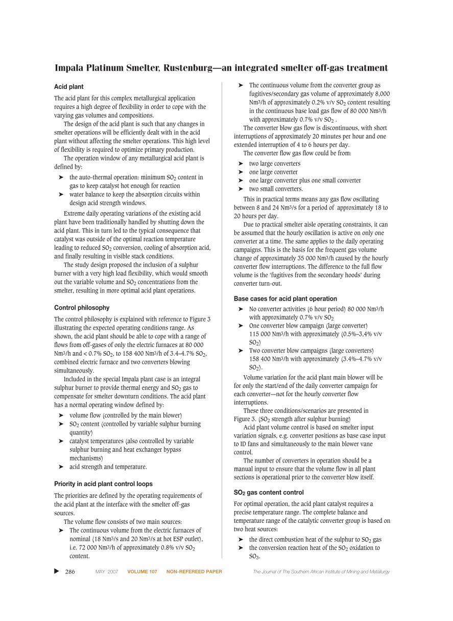
Table III
Converter off-gas design characteristics
Gas temperature at gas cleaning inlet maximum °C 550
minimum °C 250
Gas dew point at gas cleaning section inlet °C 180
Gas flow maximum Nm3/s 24
minimum Nm3/s 6
Dust loading at gas cleaning section inlet g/Nm3 g/Nm3 2
Pressure at converter hoods mm W.G. -mm W.G. –4
SO2 gas strength maximum % v/v wet 8
minimum % v/v wet 4.5
Converter off-gas analysis : SO3 g/Nm3 (wet) 5
H2O g/Nm3 (dry) 20
F- g/Nm3 (wet) 0.005–0.0016
Cl- g/Nm3 (wet) 0.03–0.11
O2 v/v (dry) 12–15 %
N2 v/v (dry) balance
Impala Platinum Smelter, Rustenburg—an integrated smelter off-gas treatment
Acid plant
The acid plant for this complex metallurgical applicationrequires a high degree of flexibility in order to cope with thevarying gas volumes and compositions.
The design of the acid plant is such that any changes insmelter operations will be efficiently dealt with in the acidplant without affecting the smelter operations. This high levelof flexibility is required to optimize primary production.
The operation window of any metallurgical acid plant isdefined by:
➤ the auto-thermal operation: minimum SO2 content ingas to keep catalyst hot enough for reaction
➤ water balance to keep the absorption circuits withindesign acid strength windows.
Extreme daily operating variations of the existing acidplant have been traditionally handled by shutting down theacid plant. This in turn led to the typical consequence thatcatalyst was outside of the optimal reaction temperatureleading to reduced SO2 conversion, cooling of absorption acid,and finally resulting in visible stack conditions.
The study design proposed the inclusion of a sulphurburner with a very high load flexibility, which would smoothout the variable volume and SO2 concentrations from thesmelter, resulting in more optimal acid plant operations.
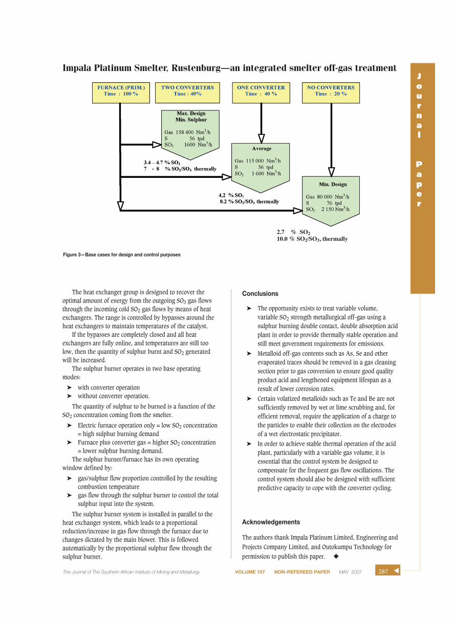
Control philosophy
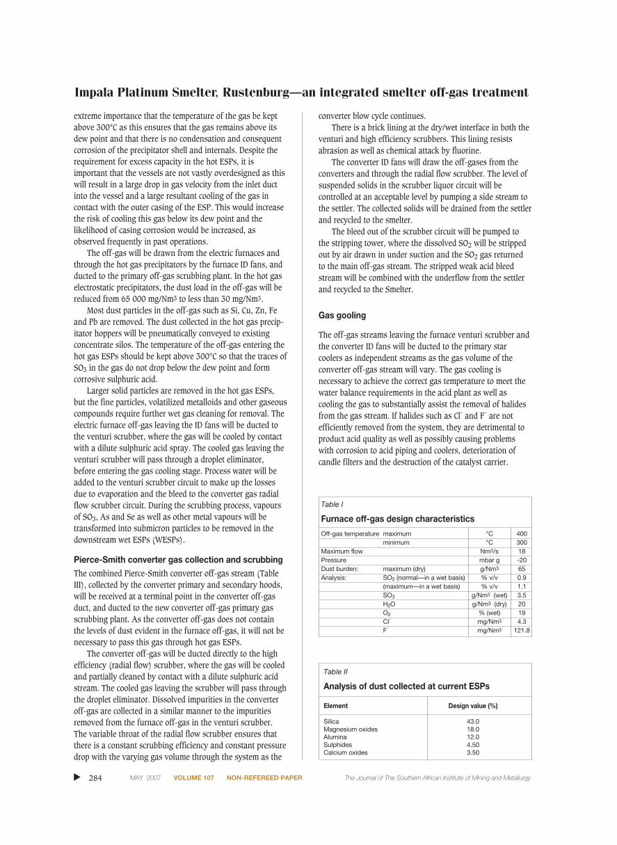
The control philosophy is explained with reference to Figure 3illustrating the expected operating conditions range. Asshown, the acid plant should be able to cope with a range offlows from off-gases of only the electric furnaces at 80 000Nm3/h and < 0.7% SO2, to 158 400 Nm3/h of 3.4–4.7% SO2,combined electric furnace and two converters blowingsimultaneously.
Included in the special Impala plant case is an integralsulphur burner to provide thermal energy and SO2 gas tocompensate for smelter downturn conditions. The acid planthas a normal operating window defined by:
➤ volume flow (controlled by the main blower)➤ SO2 content (controlled by variable sulphur burning
quantity)➤ catalyst temperatures (also controlled by variable
sulphur burning and heat exchanger bypassmechanisms)
➤ acid strength and temperature.
Priority in acid plant control loops
The priorities are defined by the operating requirements ofthe acid plant at the interface with the smelter off-gassources.
The volume flow consists of two main sources:➤ The continuous volume from the electric furnaces of
nominal (18 Nm3/s and 20 Nm3/s at hot ESP outlet),i.e. 72 000 Nm3/h of approximately 0.8% v/v SO2
content.
➤ The continuous volume from the converter group asfugitives/secondary gas volume of approximately 8,000Nm3/h of approximately 0.2% v/v SO2 content resultingin the continuous base load gas flow of 80 000 Nm3/hwith approximately 0.7% v/v SO2 .
The converter blow gas flow is discontinuous, with shortinterruptions of approximately 20 minutes per hour and oneextended interruption of 4 to 6 hours per day.
The converter flow gas flow could be from:
➤ two large converters ➤ one large converter➤ one large converter plus one small converter➤ two small converters.
This in practical terms means any gas flow oscillatingbetween 8 and 24 Nm3/s for a period of approximately 18 to20 hours per day.
Due to practical smelter aisle operating constraints, it canbe assumed that the hourly oscillation is active on only oneconverter at a time. The same applies to the daily operatingcampaigns. This is the basis for the frequent gas volumechange of approximately 35 000 Nm3/h caused by the hourlyconverter flow interruptions. The difference to the full flowvolume is the ‘fugitives from the secondary hoods’ duringconverter turn-out.
Base cases for acid plant operation
➤ No converter activities (6 hour period) 80 000 Nm3/hwith approximately 0.7% v/v SO2
➤ One converter blow campaign (large converter) 115 000 Nm3/h with approximately (0.5%–3,4% v/vSO2)
➤ Two converter blow campaigns (large converters) 158 400 Nm3/h with approximately (3.4%–4.7% v/vSO2).
Volume variation for the acid plant main blower will befor only the start/end of the daily converter campaign foreach converter—not for the hourly converter flowinterruptions.
These three conditions/scenarios are presented in Figure 3. (SO2 strength after sulphur burning)
Acid plant volume control is based on smelter inputvariation signals, e.g. converter positions as base case inputto ID fans and simultaneously to the main blower vanecontrol.
The number of converters in operation should be amanual input to ensure that the volume flow in all plantsections is operational prior to the converter blow itself.
SO2 gas content control
For optimal operation, the acid plant catalyst requires aprecise temperature range. The complete balance andtemperature range of the catalytic converter group is based ontwo heat sources:
➤ the direct combustion heat of the sulphur to SO2 gas➤ the conversion reaction heat of the SO2 oxidation to
SO3.
▲
286 MAY 2007 VOLUME 107 NON-REFEREED PAPER The Journal of The Southern African Institute of Mining and Metallurgy
The heat exchanger group is designed to recover theoptimal amount of energy from the outgoing SO3 gas flowsthrough the incoming cold SO2 gas flows by means of heatexchangers. The range is controlled by bypasses around theheat exchangers to maintain temperatures of the catalyst.
If the bypasses are completely closed and all heatexchangers are fully online, and temperatures are still toolow, then the quantity of sulphur burnt and SO2 generatedwill be increased.
The sulphur burner operates in two base operatingmodes:
➤ with converter operation➤ without converter operation.
The quantity of sulphur to be burned is a function of theSO2 concentration coming from the smelter.
➤ Electric furnace operation only = low SO2 concentration= high sulphur burning demand
➤ Furnace plus converter gas = higher SO2 concentration= lower sulphur burning demand.
The sulphur burner/furnace has its own operatingwindow defined by:
➤ gas/sulphur flow proportion controlled by the resultingcombustion temperature
➤ gas flow through the sulphur burner to control the totalsulphur input into the system.
The sulphur burner system is installed in parallel to theheat exchanger system, which leads to a proportionalreduction/increase in gas flow through the furnace due tochanges dictated by the main blower. This is followedautomatically by the proportional sulphur flow through thesulphur burner.
Conclusions
➤ The opportunity exists to treat variable volume,variable SO2 strength metallurgical off-gas using asulphur burning double contact, double absorption acidplant in order to provide thermally stable operation andstill meet government requirements for emissions.
➤ Metalloid off-gas contents such as As, Se and otherevaporated traces should be removed in a gas cleaningsection prior to gas conversion to ensure good qualityproduct acid and lengthened equipment lifespan as aresult of lower corrosion rates.
➤ Certain volatized metalloids such as Te and Be are notsufficiently removed by wet or lime scrubbing and, forefficient removal, require the application of a charge tothe particles to enable their collection on the electrodesof a wet electrostatic precipitator.
➤ In order to achieve stable thermal operation of the acidplant, particularly with a variable gas volume, it isessential that the control system be designed tocompensate for the frequent gas flow oscillations. Thecontrol system should also be designed with sufficientpredictive capacity to cope with the converter cycling.
Acknowledgements
The authors thank Impala Platinum Limited, Engineering andProjects Company Limited, and Outokumpu Technology forpermission to publish this paper. ◆
Impala Platinum Smelter, Rustenburg—an integrated smelter off-gas treatmentJournal
Paper
The Journal of The Southern African Institute of Mining and Metallurgy VOLUME 107 NON-REFEREED PAPER MAY 2007 287 ▲
Figure 3—Base cases for design and control purposes
2.7 % SO210.0 % SO2/SO3, thermally