Embed Size (px)
Citation preview
Implementation and documentation ofSensor Web Enablement at KNMI
Álvaro Plata Martínez
De Bilt, 2011 | Stageverslag

KNMI stageverslag De Bilt, 2011 PO Box 201 3730 AE De Bilt Wilhelminalaan 10 De Bilt The Netherlands http://www.knmi.nl Phone +31(0)30.220 69 11 Fax +31 (0)30.221 04 07 Title: Implementation and documentation of Sensor Web Enablement at KNMI Author: Álvaro Plata Martínez Supervisors: Wiel Wauben John van de Vegte
Implementation and documentation of Sensor Web Enablement at KNMI | Contents
Page 4 of 53
Contents
1. Introduction ...........................................................................5 2. Introduction to SWE ................................................................7
2.1. Sensor Web Enablement Concept........................................7 2.2. OGC Standard SWE...........................................................9
2.2.1. SWE Components.....................................................9 3. Installation procedure ............................................................ 16
3.1. PostGIS 1.4.0-2.............................................................. 17 3.2. Maven 2.2.1-2................................................................ 17
3.2.1. Eclipse.................................................................. 17 3.2.2. Maven integration .................................................. 17 3.2.3. Maven .................................................................. 18
3.3. 52North Sensor Observation Service.................................. 21 3.3.1. Directory structure ................................................. 23 3.3.2. Database .............................................................. 23
3.3.2.1. Database structure ........................................ 23 3.3.3. Properties configuration .......................................... 27 3.3.4. Sensor description.................................................. 28 3.3.5. Deploy.................................................................. 28 3.3.6. Test .................................................................... 29
4. Implementation .................................................................... 30 4.1. kmds2xml ..................................................................... 31 4.2. PostXML ........................................................................ 32
4.2.1. HttpClient ............................................................. 32 4.2.2. HttpCore............................................................... 33 4.2.3. Commons-logging .................................................. 33
5. Conclusions and recommendations .......................................... 35 6. References ........................................................................... 36
Appendix A .......................................................................... 37 Appendix B .......................................................................... 39 Appendix C .......................................................................... 45 Appendix D .......................................................................... 46 Appendix E .......................................................................... 51 Appendix F........................................................................... 52
Implementation and documentation of Sensor Web Enablement at KNMI | Introduction
Page 5 of 53
1 Introduction
The R&D Information and Observation Technology Division of KNMI aims to continually improve KNMI’s observation infrastructure in order to keep it up-to-date and cost-effective. For that purpose it was considered necessary to get some experience with the emerging Sensor Web Enablement (SWE) standards from the Open Geospatial Consortium (OGC). Between 2006 and 2008 KNMI participated in a national project1 during which an SWE server was installed at KNMI and fed with 10-minute data form the meteorological network. The evaluation showed that SWE was only partly available (in fact only the Sensor Observation Service SOS) and still in development. Although the desired functionality was not fully available SWE showed promising potential, particularly in respect to standardisation of the exchange of sensor data and associated meta data. Hence KNMI concluded that SWE could at that moment not be considered for operational use, but it was interesting enough to keep track of SWE developments and if possible contribute to it2. The SOS service implemented in mid 2007 on a Windows server has been operated since. In this report the work of a traineeship is presented in which a next step related to SWE was taken. Already during the previous project the SOS implementation on a Windows server caused several security issues, but porting of the 52North SOS implementation developed and tested under Windows to Linux was beyond the scope of the project. More recently, Windows server license policy made porting to Linux desirable. Hence the goals of the traineeship were:
(i) the installation of the most recent version of the SWE software suite of 52North on a Linux platform.
(ii) the continuous insertion of sensor data into the database of the SOS
service via the SOS service.
(iii) the installation of the 52N SWE visualization tool/webviewer and/or SWE extraction via GIS in order to facilitate easy visualisation of the data available via SOS.
(iv) the specification, implementation and visualization of ceilometer
backscatter profile data in SWE. This topic was selected as a case study to check whether it is feasible to handle multi-dimensional sensor data in SWE.
Due to the amount of work required for items (i) and (ii) and the time available, the latter 2 items have been removed from the work list. Furthermore it was decided that the scripts required to feed sensor data continuously to the SOS database should not be included in topic (ii). Existing infrastructure at KNMI was considered more suitable for managing and monitoring the corresponding processing and insertion steps.
Implementation and documentation of Sensor Web Enablement at KNMI | Introduction
Page 6 of 53
The outline of this report is as follows. Chapter 2 gives an overview of SWE and the related services. The two deliverables of this traineeship are reported next. The installation of current SWE software suite of 52N on a Linux platform is described in Chapter 3. Chapter 3 gives a detailed installation procedure for installing the SOS service version 3.1.1 of 52North as well as for the required software packages and relevant settings. The building blocks for the insertion of sensor data into the database of the SOS service are given in Chapter 4. This includes a description of the implemented software as well as the actual code. Finally Chapter 5 gives some conclusions and recommendations.
Implementation and documentation of Sensor Web Enablement at KNMI | Introduction to SWE
Page 7 of 53
2 Introduction to SWE
We live in a technology-based world in which a lot of different electronic devices for many different purposes are operated. The way to interconnect all those devices, such as computers, mobile phones, security cameras or sensors is Internet. In this environment, the main goal is the interoperability3, defined as a property of a product or system, whose interfaces are completely understood, to work with other products or systems, present or future, without any restricted access or implementation. Sensors, or in fact sensor networks, are the topic of this report. A sensor network is a computer accessible network of many, spatially distributed devices using sensors to monitor conditions at different locations, such as temperature, sound, vibration, pressure, motion or pollutants4. As sensors are everywhere, and there are so many different kinds of sensors, it is a great opportunity to get information of all of them.
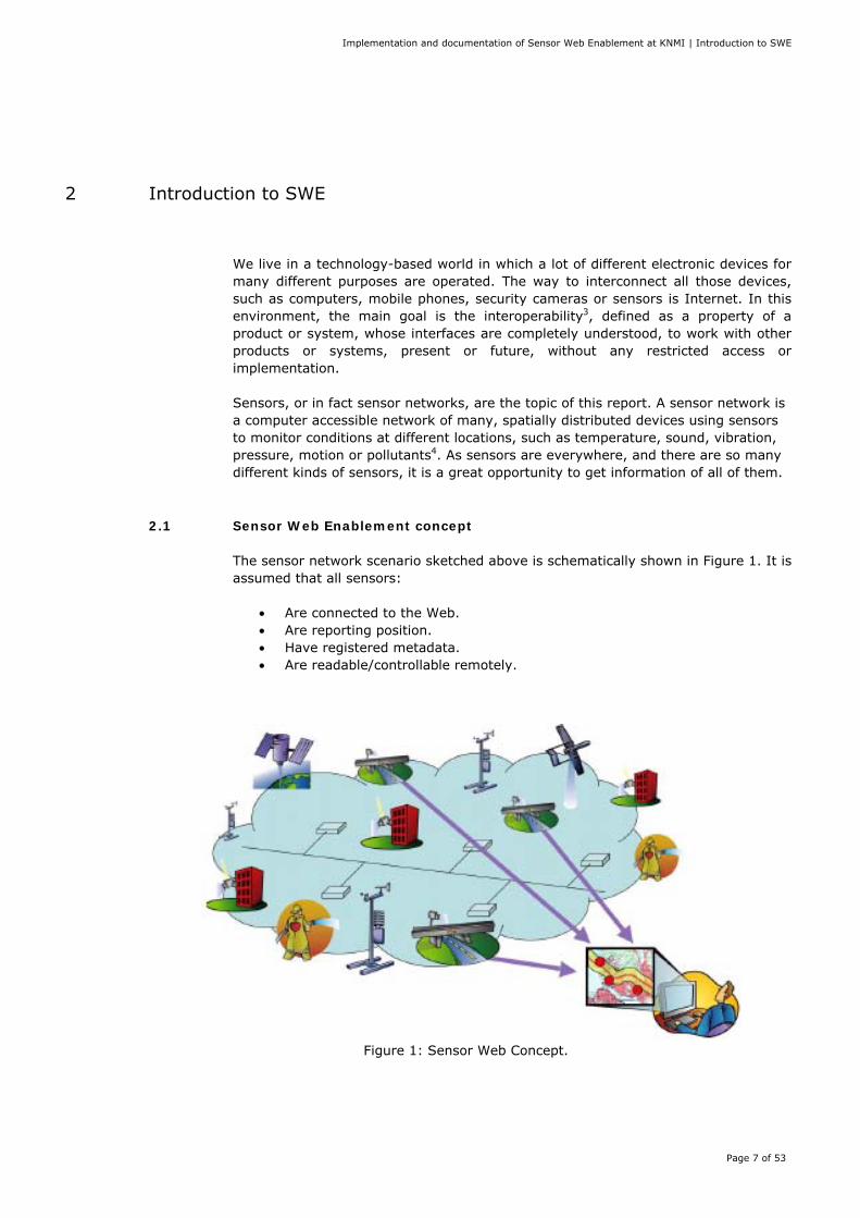
2.1 Sensor Web Enablement concept The sensor network scenario sketched above is schematically shown in Figure 1. It is assumed that all sensors:
• Are connected to the Web. • Are reporting position. • Have registered metadata. • Are readable/controllable remotely.
Figure 1: Sensor Web Concept.
Implementation and documentation of Sensor Web Enablement at KNMI | Introduction to SWE
Page 8 of 53
Hence, the objective is to make all kind of sensors via the WWW:
• Discoverable. • Accessible. • Controllable. • The framework for a WWW-based sensor web. • The foundation for ‘plug-and-play’ web-based sensor networks.
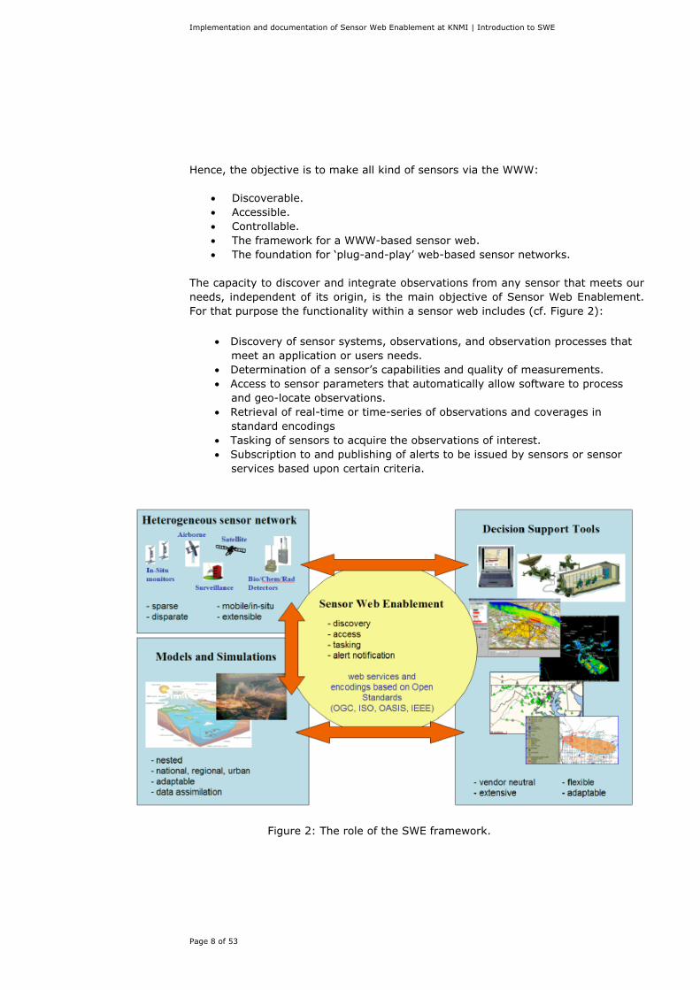
The capacity to discover and integrate observations from any sensor that meets our needs, independent of its origin, is the main objective of Sensor Web Enablement. For that purpose the functionality within a sensor web includes (cf. Figure 2):
• Discovery of sensor systems, observations, and observation processes that meet an application or users needs.
• Determination of a sensor’s capabilities and quality of measurements. • Access to sensor parameters that automatically allow software to process
and geo-locate observations. • Retrieval of real-time or time-series of observations and coverages in
standard encodings • Tasking of sensors to acquire the observations of interest. • Subscription to and publishing of alerts to be issued by sensors or sensor
services based upon certain criteria.
Figure 2: The role of the SWE framework.
Implementation and documentation of Sensor Web Enablement at KNMI | Introduction to SWE
Page 9 of 53
2.2 OGC Standard SWE The OGC standard SWE is being defined in order to facilitate the sensor web framework. SWE uses standards and protocols that are already established in the Internet. One of them is the eXtensible Markup Language (XML). Thus, XML schemas can be used to publish formal descriptions of the sensor’s capabilities, location and interfaces, so that everyone can parse and interpret the XML data, enabling e.g. an automated discovery of the existence of sensors and the evaluation of their characteristics based on their published descriptions. The protocols and interfaces through which applications and services will be able to access sensors of all types over the Web can be classified in two groups: Service Model and Information Model (cf. Figure 3).
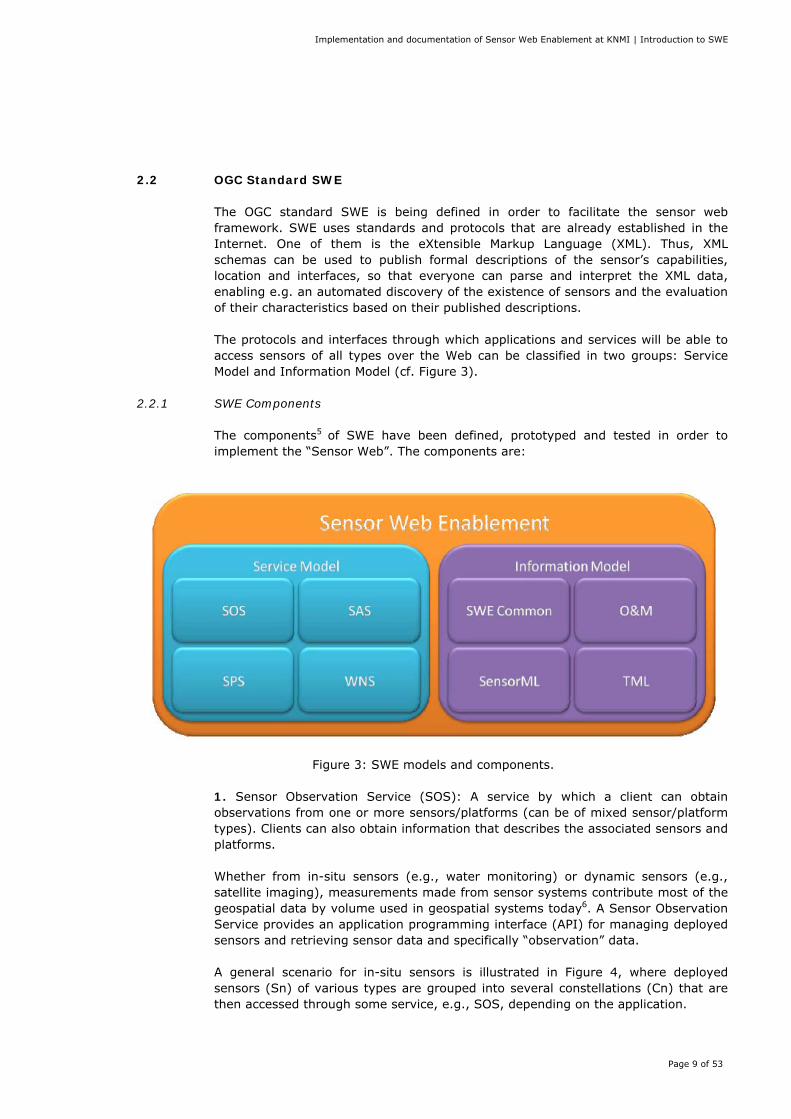
2.2.1 SWE Components The components5 of SWE have been defined, prototyped and tested in order to implement the “Sensor Web”. The components are:
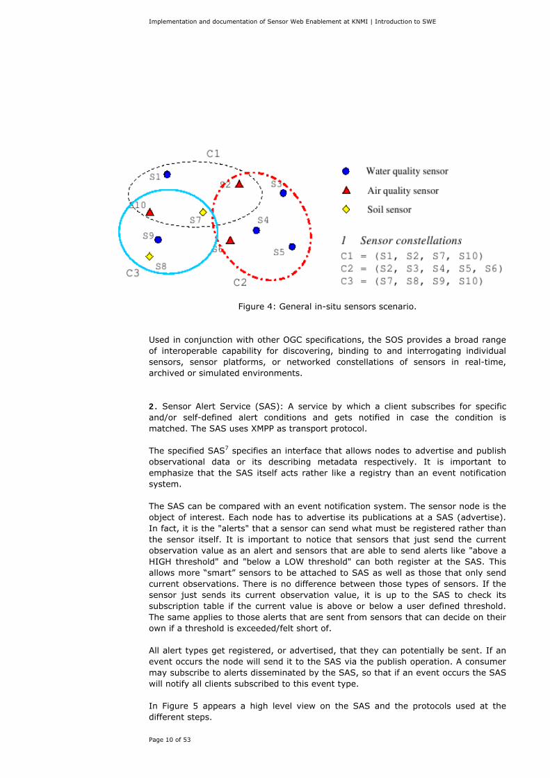
Figure 3: SWE models and components. 1. Sensor Observation Service (SOS): A service by which a client can obtain observations from one or more sensors/platforms (can be of mixed sensor/platform types). Clients can also obtain information that describes the associated sensors and platforms. Whether from in-situ sensors (e.g., water monitoring) or dynamic sensors (e.g., satellite imaging), measurements made from sensor systems contribute most of the geospatial data by volume used in geospatial systems today6. A Sensor Observation Service provides an application programming interface (API) for managing deployed sensors and retrieving sensor data and specifically “observation” data. A general scenario for in-situ sensors is illustrated in Figure 4, where deployed sensors (Sn) of various types are grouped into several constellations (Cn) that are then accessed through some service, e.g., SOS, depending on the application.
Implementation and documentation of Sensor Web Enablement at KNMI | Introduction to SWE
Page 10 of 53
Figure 4: General in-situ sensors scenario.
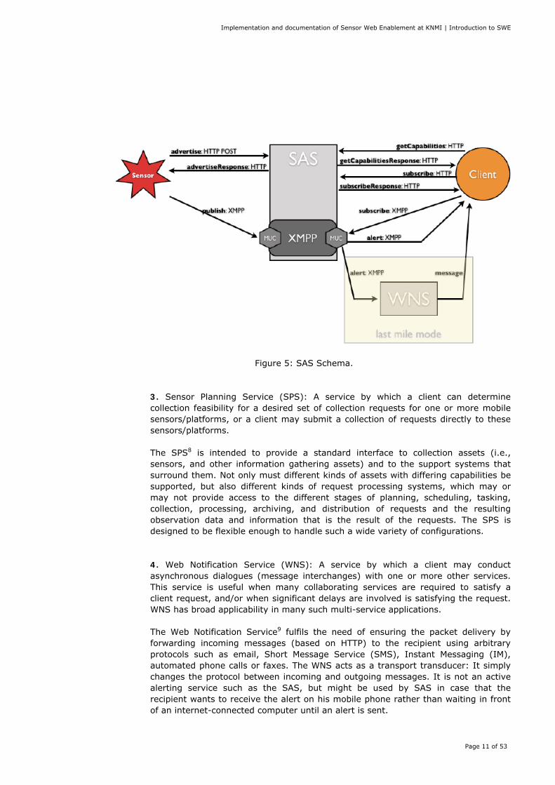
Used in conjunction with other OGC specifications, the SOS provides a broad range of interoperable capability for discovering, binding to and interrogating individual sensors, sensor platforms, or networked constellations of sensors in real-time, archived or simulated environments. 2. Sensor Alert Service (SAS): A service by which a client subscribes for specific and/or self-defined alert conditions and gets notified in case the condition is matched. The SAS uses XMPP as transport protocol. The specified SAS7 specifies an interface that allows nodes to advertise and publish observational data or its describing metadata respectively. It is important to emphasize that the SAS itself acts rather like a registry than an event notification system. The SAS can be compared with an event notification system. The sensor node is the object of interest. Each node has to advertise its publications at a SAS (advertise). In fact, it is the "alerts" that a sensor can send what must be registered rather than the sensor itself. It is important to notice that sensors that just send the current observation value as an alert and sensors that are able to send alerts like "above a HIGH threshold" and "below a LOW threshold" can both register at the SAS. This allows more “smart” sensors to be attached to SAS as well as those that only send current observations. There is no difference between those types of sensors. If the sensor just sends its current observation value, it is up to the SAS to check its subscription table if the current value is above or below a user defined threshold. The same applies to those alerts that are sent from sensors that can decide on their own if a threshold is exceeded/felt short of. All alert types get registered, or advertised, that they can potentially be sent. If an event occurs the node will send it to the SAS via the publish operation. A consumer may subscribe to alerts disseminated by the SAS, so that if an event occurs the SAS will notify all clients subscribed to this event type. In Figure 5 appears a high level view on the SAS and the protocols used at the different steps.
Implementation and documentation of Sensor Web Enablement at KNMI | Introduction to SWE
Page 11 of 53
Figure 5: SAS Schema.
3. Sensor Planning Service (SPS): A service by which a client can determine collection feasibility for a desired set of collection requests for one or more mobile sensors/platforms, or a client may submit a collection of requests directly to these sensors/platforms. The SPS8 is intended to provide a standard interface to collection assets (i.e., sensors, and other information gathering assets) and to the support systems that surround them. Not only must different kinds of assets with differing capabilities be supported, but also different kinds of request processing systems, which may or may not provide access to the different stages of planning, scheduling, tasking, collection, processing, archiving, and distribution of requests and the resulting observation data and information that is the result of the requests. The SPS is designed to be flexible enough to handle such a wide variety of configurations. 4. Web Notification Service (WNS): A service by which a client may conduct asynchronous dialogues (message interchanges) with one or more other services. This service is useful when many collaborating services are required to satisfy a client request, and/or when significant delays are involved is satisfying the request. WNS has broad applicability in many such multi-service applications. The Web Notification Service9 fulfils the need of ensuring the packet delivery by forwarding incoming messages (based on HTTP) to the recipient using arbitrary protocols such as email, Short Message Service (SMS), Instant Messaging (IM), automated phone calls or faxes. The WNS acts as a transport transducer: It simply changes the protocol between incoming and outgoing messages. It is not an active alerting service such as the SAS, but might be used by SAS in case that the recipient wants to receive the alert on his mobile phone rather than waiting in front of an internet-connected computer until an alert is sent.
Implementation and documentation of Sensor Web Enablement at KNMI | Introduction to SWE
Page 12 of 53
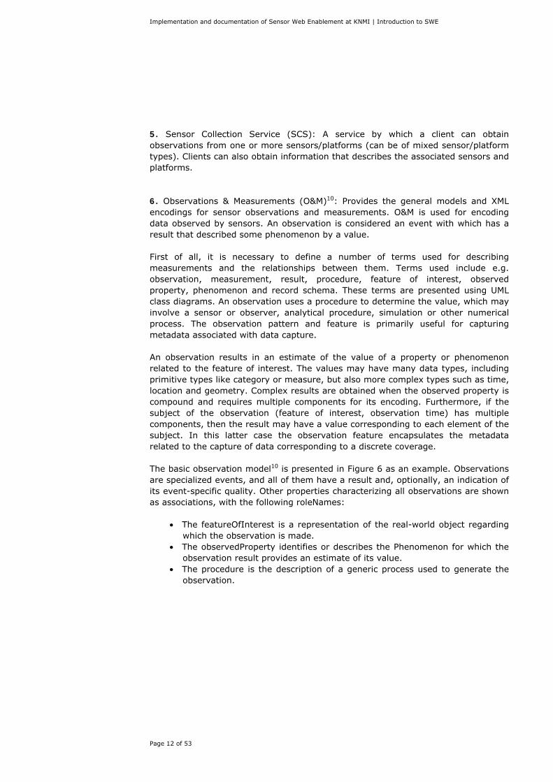
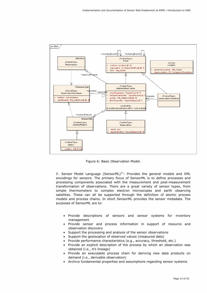
5. Sensor Collection Service (SCS): A service by which a client can obtain observations from one or more sensors/platforms (can be of mixed sensor/platform types). Clients can also obtain information that describes the associated sensors and platforms. 6. Observations & Measurements (O&M)10: Provides the general models and XML encodings for sensor observations and measurements. O&M is used for encoding data observed by sensors. An observation is considered an event with which has a result that described some phenomenon by a value. First of all, it is necessary to define a number of terms used for describing measurements and the relationships between them. Terms used include e.g. observation, measurement, result, procedure, feature of interest, observed property, phenomenon and record schema. These terms are presented using UML class diagrams. An observation uses a procedure to determine the value, which may involve a sensor or observer, analytical procedure, simulation or other numerical process. The observation pattern and feature is primarily useful for capturing metadata associated with data capture. An observation results in an estimate of the value of a property or phenomenon related to the feature of interest. The values may have many data types, including primitive types like category or measure, but also more complex types such as time, location and geometry. Complex results are obtained when the observed property is compound and requires multiple components for its encoding. Furthermore, if the subject of the observation (feature of interest, observation time) has multiple components, then the result may have a value corresponding to each element of the subject. In this latter case the observation feature encapsulates the metadata related to the capture of data corresponding to a discrete coverage. The basic observation model10 is presented in Figure 6 as an example. Observations are specialized events, and all of them have a result and, optionally, an indication of its event-specific quality. Other properties characterizing all observations are shown as associations, with the following roleNames:
• The featureOfInterest is a representation of the real-world object regarding which the observation is made.
• The observedProperty identifies or describes the Phenomenon for which the observation result provides an estimate of its value.
• The procedure is the description of a generic process used to generate the observation.
Implementation and documentation of Sensor Web Enablement at KNMI | Introduction to SWE
Page 13 of 53
Figure 6: Basic Observation Model.
7. Sensor Model Language (SensorML)11: Provides the general models and XML encodings for sensors. The primary focus of SensorML is to define processes and processing components associated with the measurement and post-measurement transformation of observations. There are a great variety of sensor types, from simple thermometers to complex electron microscopes and earth observing satellites. These can all be supported through the definition of atomic process models and process chains. In short SensorML provides the sensor metadata. The purposes of SensorML are to:
• Provide descriptions of sensors and sensor systems for inventory management
• Provide sensor and process information in support of resource and observation discovery
• Support the processing and analysis of the sensor observations • Support the geolocation of observed values (measured data) • Provide performance characteristics (e.g., accuracy, threshold, etc.) • Provide an explicit description of the process by which an observation was
obtained (i.e., it’s lineage) • Provide an executable process chain for deriving new data products on
demand (i.e., derivable observation) • Archive fundamental properties and assumptions regarding sensor systems
Implementation and documentation of Sensor Web Enablement at KNMI | Introduction to SWE
Page 14 of 53
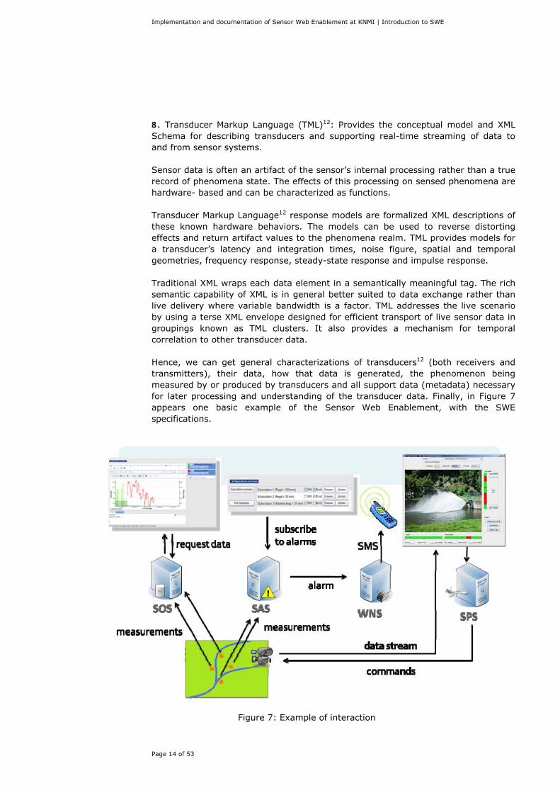
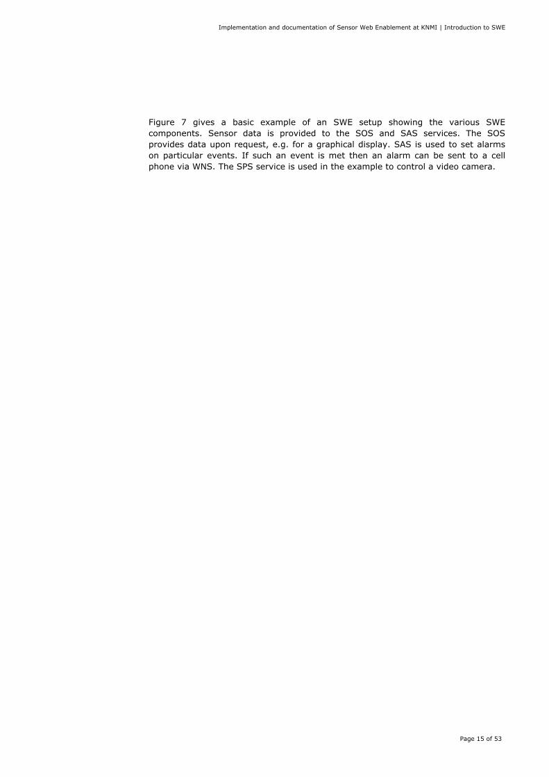
8. Transducer Markup Language (TML)12: Provides the conceptual model and XML Schema for describing transducers and supporting real-time streaming of data to and from sensor systems. Sensor data is often an artifact of the sensor’s internal processing rather than a true record of phenomena state. The effects of this processing on sensed phenomena are hardware- based and can be characterized as functions. Transducer Markup Language12 response models are formalized XML descriptions of these known hardware behaviors. The models can be used to reverse distorting effects and return artifact values to the phenomena realm. TML provides models for a transducer’s latency and integration times, noise figure, spatial and temporal geometries, frequency response, steady-state response and impulse response. Traditional XML wraps each data element in a semantically meaningful tag. The rich semantic capability of XML is in general better suited to data exchange rather than live delivery where variable bandwidth is a factor. TML addresses the live scenario by using a terse XML envelope designed for efficient transport of live sensor data in groupings known as TML clusters. It also provides a mechanism for temporal correlation to other transducer data. Hence, we can get general characterizations of transducers12 (both receivers and transmitters), their data, how that data is generated, the phenomenon being measured by or produced by transducers and all support data (metadata) necessary for later processing and understanding of the transducer data. Finally, in Figure 7 appears one basic example of the Sensor Web Enablement, with the SWE specifications.
Figure 7: Example of interaction
Implementation and documentation of Sensor Web Enablement at KNMI | Introduction to SWE
Page 15 of 53
Figure 7 gives a basic example of an SWE setup showing the various SWE components. Sensor data is provided to the SOS and SAS services. The SOS provides data upon request, e.g. for a graphical display. SAS is used to set alarms on particular events. If such an event is met then an alarm can be sent to a cell phone via WNS. The SPS service is used in the example to control a video camera.
Implementation and documentation of Sensor Web Enablement at KNMI | Installation procedure
Page 16 of 53
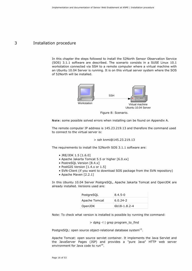
3 Installation procedure
In this chapter the steps followed to install the 52North Sensor Observation Service (SOS) 3.1.1 software are described. The scenario consists in a SUSE Linux 10.1 workstation connected via SSH to a remote computer where a virtual machine with an Ubuntu 10.04 Server is running. It is on this virtual server system where the SOS of 52North will be installed.
Virtual machineUbuntu 10.04 Server
SSH
Workstation
Figure 8: Scenario.
Note: some possible solved errors when installing can be found on Appendix A. The remote computer IP address is 145.23.219.13 and therefore the command used to connect to the virtual server is:
> ssh [email protected] The requirements to install the 52North SOS 3.1.1 software are:
• JRE/JDK 1.5 [1.6.0] • Apache Jakarta Tomcat 5.5 or higher [6.0.xx] • PostreSQL Version [8.4.x] • PostGIS Version [1.4.x or 1.5] • SVN-Client (if you want to download SOS package from the SVN repository) • Apache Maven [2.2.1]
In this Ubuntu 10.04 Server PostgreSQL, Apache Jakarta Tomcat and OpenJDK are already installed. Versions used are:
PostgreSQL 8.4.5-0
Apache Tomcat 6.0.24-2
OpenJDK 6b18-1.8.2-4
Note: To check what version is installed is possible by running the command:
> dpkg -l | grep program_to_find PostgreSQL: open source object-relational database system13. Apache Tomcat: open source servlet container. It implements the Java Servlet and the JavaServer Pages (JSP) and provides a "pure Java" HTTP web server environment for Java code to run14.
Implementation and documentation of Sensor Web Enablement at KNMI | Installation procedure
Page 17 of 53
Open Java Development Kit (OpenJDK): open source implementation of the Java Platform Standard Edition15. As it is supposed that the official Sun Java Development Kit and Java Runtime Environment will be used, these packages have to be installed by typing in the console:
> sudo apt-get install sun-java6-jdk > sudo apt-get install sun-java6-jre
The manual installation of PostGIS, Maven and 52North SOS is described below.
3.1 PostGIS 1.4.0-2 PostGIS adds support for geographic objects to the PostgreSQL object-relational database. To install it is possible by just running the command:
> sudo apt-get install postgis Although in this point PostGIS is already installed in the computer as a part of PostgreSQL, the PostGIS template is not available when creating new databases yet, as it will be mentioned in the ‘Create database’ section. Note: another option is to install PostGIS by running:
> sudo apt-get install postgresql-8.4-postgis
3.2 Maven 2.2.1-2 Apache Maven is a software project management and comprehension tool. Based on the concept of a project object model (POM), Maven can manage a project's build, reporting and documentation from a central piece of information16. Note: It requires Java JDK 1.4 or newer, hence it should be installed after JDK.
3.2.1 Eclipse Eclipse17 is a multi-language software development environment comprising an integrated development environment (IDE) and an extensible plug-in system. It is written mostly in Java and can be used to develop applications in Java and, by means of various plug-ins, other programming languages including Ada, C, C++, COBOL, Perl, PHP, Python, Scala, Clojure, and Scheme. To install eclipse the command used is:
> sudo apt-get install eclipse
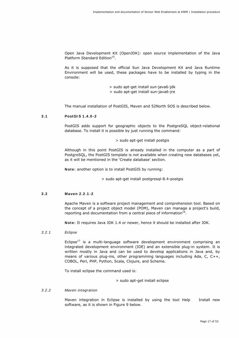
3.2.2 Maven integration Maven integration in Eclipse is installed by using the tool Help � Install new software, as it is shown in Figure 9 below.
Implementation and documentation of Sensor Web Enablement at KNMI | Installation procedure
Page 18 of 53
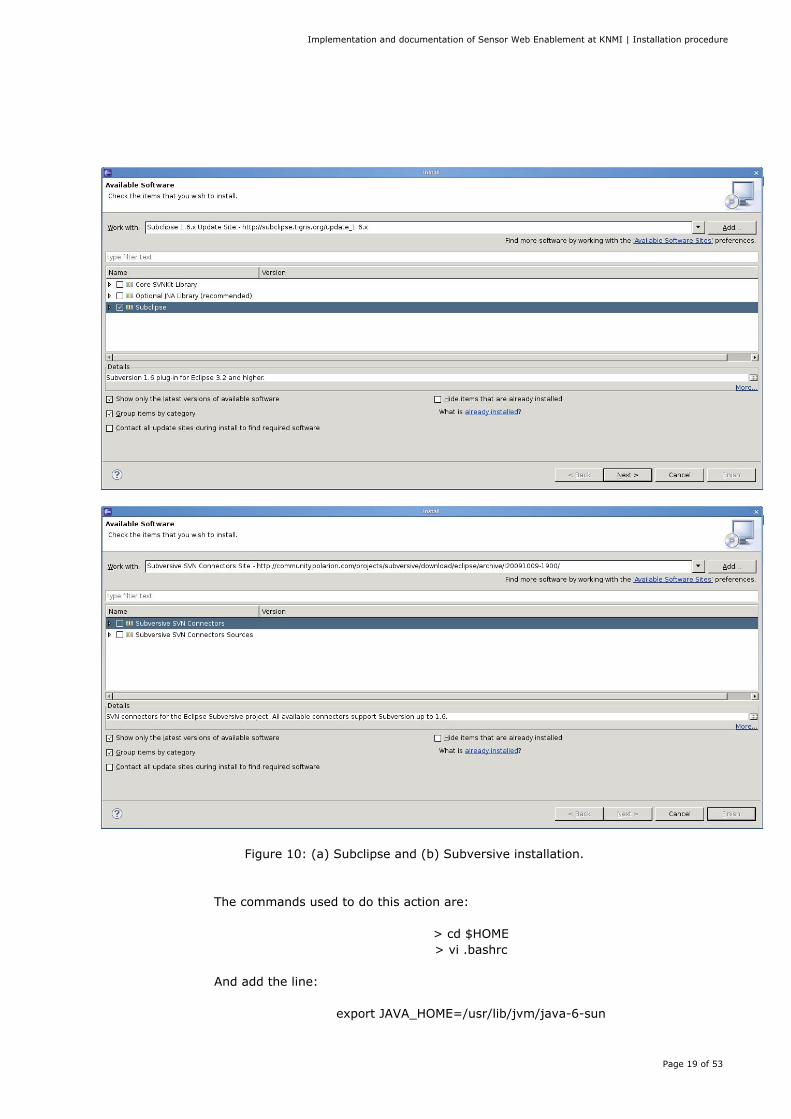
Figure 9: Install maven integration. The next step is to get the subversion client:
> sudo apt-get install subversion In the same way followed to install Maven Integration we can install the Subclipse and Subversive plugins as well, as it is shown in the Figure 10 (a) and (b) respectively.
3.2.3 Maven Before to install Maven, it is necessary to set the environment variable $JAVA_HOME to the Java installation folder, in this case:
/usr/lib/jvm/java-6-sun This must be changed in the .bashrc file so that the change is permanent because otherwise it would be necessary to set every time that a new shell is open.
Implementation and documentation of Sensor Web Enablement at KNMI | Installation procedure
Page 19 of 53
Figure 10: (a) Subclipse and (b) Subversive installation. The commands used to do this action are:
> cd $HOME > vi .bashrc
And add the line:
export JAVA_HOME=/usr/lib/jvm/java-6-sun
Implementation and documentation of Sensor Web Enablement at KNMI | Installation procedure
Page 20 of 53
Once it is done it is possible to install Maven:
> sudo apt-get install maven2 The next step is to configure Maven by editing the settings.xml file located in /etc/maven2/. 1) Under the <settings> tag the path to the local repository is inserted. <localRepository> /home/knmi/maven2repository </localRepository>
Note: This repository has been created by the user: 2) Under the <profiles> tag the following profile is inserted: <profile> <id>52n-start</id> <repositories> <repository> <id>n52-releases</id> <name>52n Releases</name> <url>http://52north.org/maven/repo/releases</url> <releases> <enabled>true</enabled> </releases> <snapshots> <enabled>false</enabled> </snapshots> </repository> <repository> <id>geotools</id> <name>Geotools repository</name> <url>http://maven.geotools.fr/repository</url> </repository> <repository> <id>Refractions</id> <name>Refractions repository</name> <url>http://lists.refractions.net/m2</url> </repository> <repository> <id>Apache</id> <name>Apache repository</name> <url>http://repo1.maven.org/maven2</url> </repository> </repositories> </profile>
3) After the <profiles> Section the following active profile is inserted: <activeProfiles>
Implementation and documentation of Sensor Web Enablement at KNMI | Installation procedure
Page 21 of 53
<activeProfile>52n-start</activeProfile> </activeProfiles>
In this point, basic repositories and profiles to allow Maven to find modules on which the 52N SOS depends have been added. The final step is to configure the properties, by editing the build.properties file located in /home/knmi/52n-sos/conf/: # Tomcat Manager username **HAS TO BE CHANGED** deploy.tomcat.manager.username=admin # Tomcat Manager password **HAS TO BE CHANGED** deploy.tomcat.manager.password=tomcat
Previously, the tomcat-users.xml located in /etc/tomcat6/ has to be edited: <tomcat-users> <role rolename="manager"/> <user username="admin" password="tomcat" roles="admin,manager"/> </tomcat-users>
3.3 52North Sensor Observation Service The Sensor Observation Service18 aggregates readings from live, in-situ and remote sensors. The service provides an interface to make sensors and sensor data archives accessible via an interoperable web based interface. Four profiles are defined within the SOS specification: core, transactional, enhanced, and entire. The current release implements the core profile comprising of the mandatory operations:
• GetCapabilities, for requesting a self-description of the service. • GetObservation, for requesting the pure sensor data encoded in
Observation&Measurements (O&M). • DescribeSensor, for requesting information about the sensor itself, encoded
in a Sensor Model Language (SensorML) instance document. The recent development snapshot implements also the following optional operations:
• GetFeatureOfInterest, for requesting the GML encoded representation of the feature that is the target of the observation.
• GetResult, for periodically polling of sensor data. • RegisterSensor, for registering new sensors.
Implementation and documentation of Sensor Web Enablement at KNMI | Installation procedure
Page 22 of 53
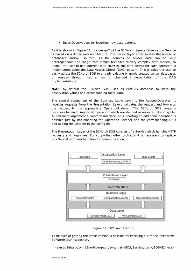
• InsertObservation, for inserting new observations. As it is shown in Figure 11, the design19 of the 52°North Sensor Observation Service is based on a 4-tier web architecture. The lowest layer encapsulates the access of databases and/or -sources. As the sources of sensor data can be very heterogeneous and range from simple text files to very complex data models, to enable the user to use different data sources, the data access for each operation is implemented using the Data Access Object (DAO) pattern. This enables the user to easily adjust the 52North SOS to already existing or newly created sensor databases or sources through just a new or changed implementation of the DAO implementations. Note: by default the 52North SOS uses as PostGIS database to store the observation values and corresponding meta data. The central component of the Business Logic Layer is the RequestOperator. It receives requests from the Presentation Layer, validates the request and forwards the request to the appropriate OperationListener. The 52North SOS contains Listeners for each supported operation which are defined in an external config file. All Listeners implement a common interface, so supporting an additional operation is possible just by implementing the Operation Listener and the corresponding DAO and adding the Listener in the config file. The Presentation Layer of the 52North SOS consists of a Servlet which handles HTTP requests and responses. For supporting other protocols it is necessary to replace this Servlet with another class for communication.
Figure 11: SOS architecture. To be sure of getting the latest version is possible by checking out the sources from 52°North-SVN-Repository. > svn co https://svn.52north.org/svn/swe/main/SOS/Service/trunk/SOS/52n-sos/
Implementation and documentation of Sensor Web Enablement at KNMI | Installation procedure
Page 23 of 53
3.3.1 Directory structure The directory structure of the main /home/knmi/52n-sos/ directory of 52North SOS 3.1.1 is as follows:
• 52n-sos-coding: source files
• 52n-sos-core: source files
• 52n-sos-dao-postgis: source files
• 52n-sos-ogc: source files
• 52n-sos-services: source files.
• db: sql scripts for the DB schema
• doc: installation guide
• jmeter: Apache Jmeter test files
3.3.2 Database To manage databases It is possible to use pgAdmin, which is graphical front-end administration tool for PostgreSQL. However, when trying to create a database using pgadmin3, it wasn't work. It was solved by creating the database within a shell, as the superuser “postgres”:
> psql -U postgres And then:
> create database "SOSDatabase" with encoding='UTF8' TEMPLATE=postgistemplate connection limit=-1;
Now database is created. Then, for being able to use the PostGIS template: > createlang plpgsql SOSDatabase > psql -d SOSDatabase -f /usr/share/postgresql/8.4/contrib/postgis.sql > psql -d SOSDatabase -f /usr/share/postgresql/8.4/contrib/spatial_ref_sys.sql > psql -d SOSDatabase -f /usr/share/postgresql/8.4/contrib/postgis_comments.sql
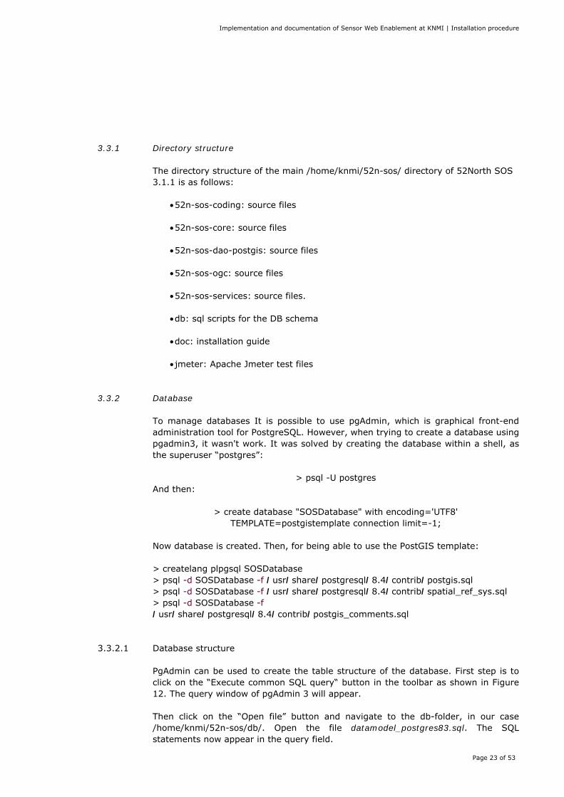
3.3.2.1 Database structure PgAdmin can be used to create the table structure of the database. First step is to click on the “Execute common SQL query“ button in the toolbar as shown in Figure 12. The query window of pgAdmin 3 will appear. Then click on the “Open file” button and navigate to the db-folder, in our case /home/knmi/52n-sos/db/. Open the file datamodel_postgres83.sql. The SQL statements now appear in the query field.
Implementation and documentation of Sensor Web Enablement at KNMI | Installation procedure
Page 24 of 53
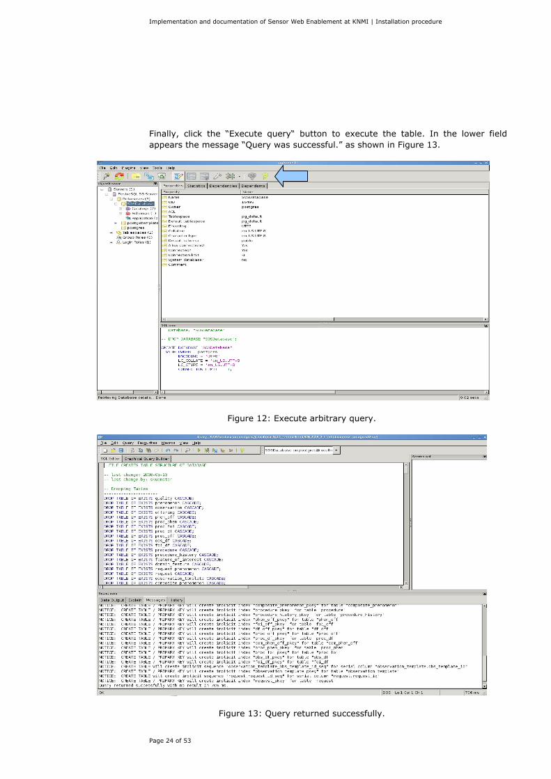
Finally, click the “Execute query“ button to execute the table. In the lower field appears the message “Query was successful.” as shown in Figure 13.
Figure 12: Execute arbitrary query.
Figure 13: Query returned successfully.
Implementation and documentation of Sensor Web Enablement at KNMI | Installation procedure
Page 25 of 53
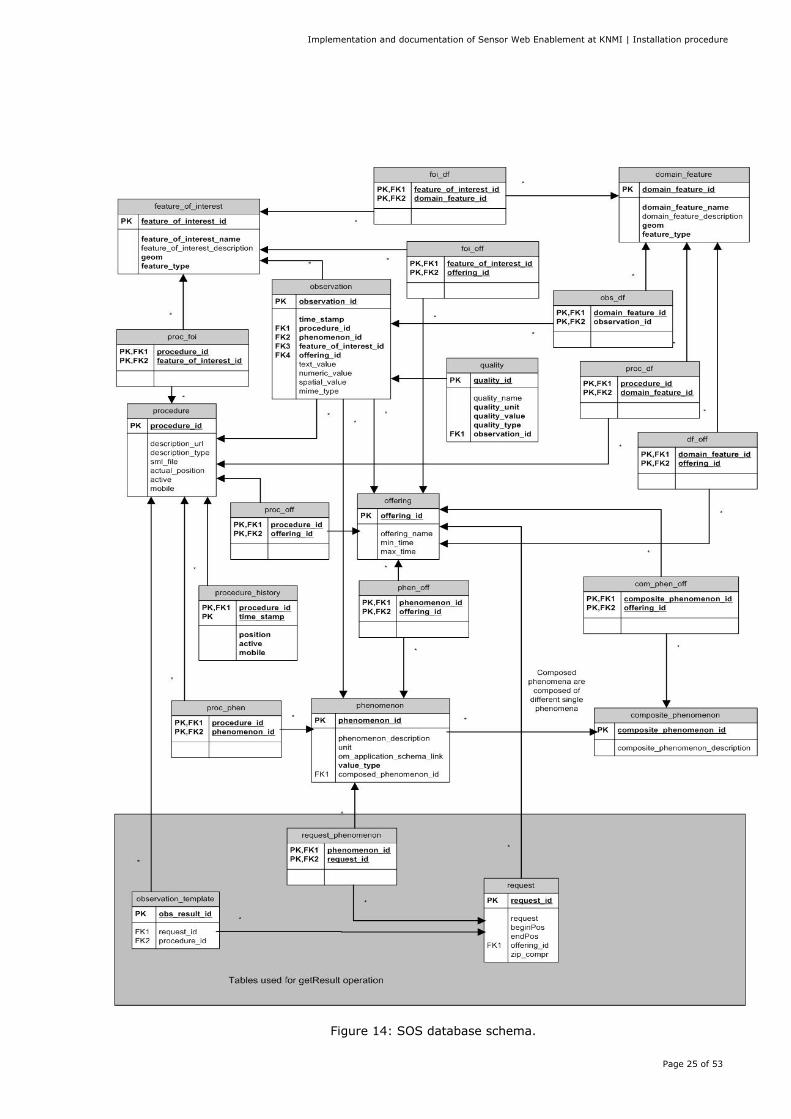
Figure 14: SOS database schema.
Implementation and documentation of Sensor Web Enablement at KNMI | Installation procedure
Page 26 of 53
The table structure of the database20 is shown in Figure 14. The tables in the grey box will be automatically used by the SOS to store request parameters for a later getResult operation request. The rest of the figure shows the “data“ tables of the SOS database. The SOS will use the tables to answer incoming requests or to update the values. The following tables are contained:
1. feature_of_interest table – the feature_of_interest table stores data about the feature of interest. The geom column holds the geometry of the feature_of_interest and is of the PostGIS type geometry.
2. foi_off table – the foi_off table realizes the many-to-many relationship between offerings and features of interest.
3. foi_df table – the foi_df table realizes the many-to-many relationship between domain features and features of interest.
4. proc_foi table – the proc_foi table realizes the many-to-many relationship between procedures and features of interest.
5. Observation table – the observation table aggregates the data of an observation event like time, procedure (sensor or group of sensors), the feature of interest and the observation value, which is stored in a separate table. Note that the columns observation_id, feature_of_interest_id, and procedure_id are foreign keys. You have to ensure that the values you want to insert in this columns are contained in the tables they reference on.
6. feature_of_interest table – the feature_of_interest table stores data about the feature of interest. The geom column holds the geometry of the feature_of_interest and is of the PostGIS type geometry.
7. foi_off table – the foi_off table realizes the many-to-many relationship between offerings and features of interest.
8. foi_df table – the foi_df table realizes the many-to-many relationship between domain features and features of interest.
9. proc_foi table – the proc_foi table realizes the many-to-many relationship between procedures and features of interest.
10. Observation table – the observation table aggregates the data of an observation event like time, procedure (sensor or group of sensors), the feature of interest and the observation value, which is stored in a separate table. Note that the columns observation_id, feature_of_interest_id, and procedure_id are foreign keys. You have to ensure that the values you want to insert in this columns are contained in the tables they reference on.
11. quality table – the quality table stores quality attributes for an observation. Qualities are optional and have not to be set. In this case set 'conf.sos.supportsQualit'y in config.properties file to 'false'. 1. procedure table – the procedure table stores data about the procedure. Only the procedure_id which should be the URN of the procedure as specified by the OGC must be contained. 1. proc_off table – the proc_off table realizes the many-to-many relationship between procedures and offerings.
12. offering table – the offering table stores each offering of this SOS. This table is only used when the SOS is initialized to read in the offerings of this SOS (e.g. gauge height) and the phenomena which are related to each offering. Note that if you have inserted new offerings, you have to restart your SOS to enable the changes.
13. phen_off table - the phen_off table is created to represent the many-to-many relationship between offerings and phenomena.
14. composite_phenomenon table – the composite_phenomenon stores composite phenomena.
Implementation and documentation of Sensor Web Enablement at KNMI | Installation procedure
Page 27 of 53
15. com_phen_off table – the com_phen_off table realizes the many-to-many relationship between composite phenomena and offerings. Remember to insert the relationships if you have inserted new composite phenomena and/or new offerings!
16. phenomenon table – the phenomenon table represents phenomena. In the context of the new SOS specification phenomena are also called observedProperties. Only the phenomenon_id and value_type are required. The phenomenon_id should contain the URN of the phenomenon as specified by the OGC. The possible values of the value_type column are: integerType, doubleType, floatType for numerical values textType for textual (categorical) values
17. proc_phen table – the proc_phen table realizes the many-to-many relationship between procedures and phenomena.
18. domain_feature table – the domain_feature table stores domain features for the SOS. It represents an area which contains many sensors. In other words it is the investigation area.
19. df_off table - the df_off table realizes the many-to-many relationship between domain features and offerings.
20. proc_df table - the proc_df table realizes the many-to-many relationship between procedures and domain features. Remember to insert the relationships if you have inserted new procedures and/or new domain features!
21. proc_off table – the proc_off table realizes the many-to-many relationship between procedures and offerings.
22. procedure_history table – the procedure history is needed for the mobile SOS. In this table currently old positions of the registered sensors are stored.
3.3.3 Properties configuration Next step is to adjust the capabilities skeleton by editing the serviceIdentification and serviceProvider. This has to be modified in the build.properties file located in:
/home/knmi/52n-sos/conf/
######################### # capabilities settings # ######################### #service identification conf.sos.capabilities.identification.title=KNMI SOS conf.sos.capabilities.identification.abstract=52N SOS at KNMI, De Bilt, Netherlands conf.sos.capabilities.identification.keywords=water level, gauge height, waterspeed conf.sos.capabilities.identification.servicetype=OGC:SOS conf.sos.capabilities.identification.fees=NONE conf.sos.capabilities.identification.accessconstrains=NONE # absolute path and name of the service identification file for the capabilities document (OPTIONAL)
Implementation and documentation of Sensor Web Enablement at KNMI | Installation procedure
Page 28 of 53
conf.sos.serviceidentificationfile=/home/knmi/52n-sos/52n-sos-service/src/main/webapp/WEB-INF/conf/capabilities/serviceIdentification.xml # service provider conf.sos.capabilities.provider.name=52North conf.sos.capabilities.provider.site=http://52north.org/swe conf.sos.capabilities.provider.individual.name=TBA conf.sos.capabilities.provider.position.name=TBA conf.sos.capabilities.provider.phone=+49(0)251/396 371-0 conf.sos.capabilities.provider.address=Marin-Luther-King-Weg 24 conf.sos.capabilities.provider.city=Muenster conf.sos.capabilities.provider.zip=48155 conf.sos.capabilities.provider.state=North Rhine-Westphalia conf.sos.capabilities.provider.country=Germany [email protected] # absolute path and name of the service provider file for the capabilities document(OPTIONAL) conf.sos.serviceproviderfile=/home/knmi/52n-sos/52n-sos-service/src/main/webapp/WEB-INF/conf/capabilities/serviceProvider.xml
These changes will be saved in the serviceIdentification.xml and serviceProvider.xml located in: /home/knmi/52n-sos/52n-sos-service/src/main/webapp/WEB-INF/conf/capabilities
3.3.4 Sensor description It is necessary to create a SensorML instance document for each sensor and store in the folder:
/home/knmi/52n-sos/52n-sos-service/src/main/webapp/WEB-INF/conf/sensors/ In this case the file procedure06260.xml (see Appendix B) has been used. That file defines the information regarding the sensor, e.g. its location and whether it is mobile or not, and the phenomena that is able to measure.
3.3.5 Deploy Important: Before deploying, make sure that Tomcat and Postgres are started. For deploying it is necessary to go to the project's folder, in our case:
/home/knmi/52n-sos/
And run the command:
> mvn -Pwith-deploy install
Implementation and documentation of Sensor Web Enablement at KNMI | Installation procedure
Page 29 of 53
3.3.6 Tests It is possible to test whether SOS is properly working. First and the simplest test is to execute the test.sql file located in /home/knmi/52n-sos/db/, by running the commands:
> sudo su postgres > psql -d SOSDatabase -f /home/knmi/52N-SOS-3.1.1/db/test.sql
Another test is to make a GetCapabilities-Request. It can be done using two ways:
1. via HTTP GET Type in the navigation bar of your browser: http://localhost:8080/52nSOSv3/sos?REQUEST=GetCapabilities&SERVICE=SOS&AC
CEPTVERSIONS=1.0.0 The capabilities response document will be shown in the browser. It is possible to extend the request above through appending the optional parameters SECTIONS, ACCEPTFORMATS and UPDATESEQUENCE.
2. via HTTP POST: Open your Internet browser. You can find the SOS-Test Client under by writing in the navigation bar:
http://localhost:8080/52nSOSv3/testClient-v2.html.
Implementation and documentation of Sensor Web Enablement at KNMI | Insert Observation
Page 30 of 53
4 Insert Observation
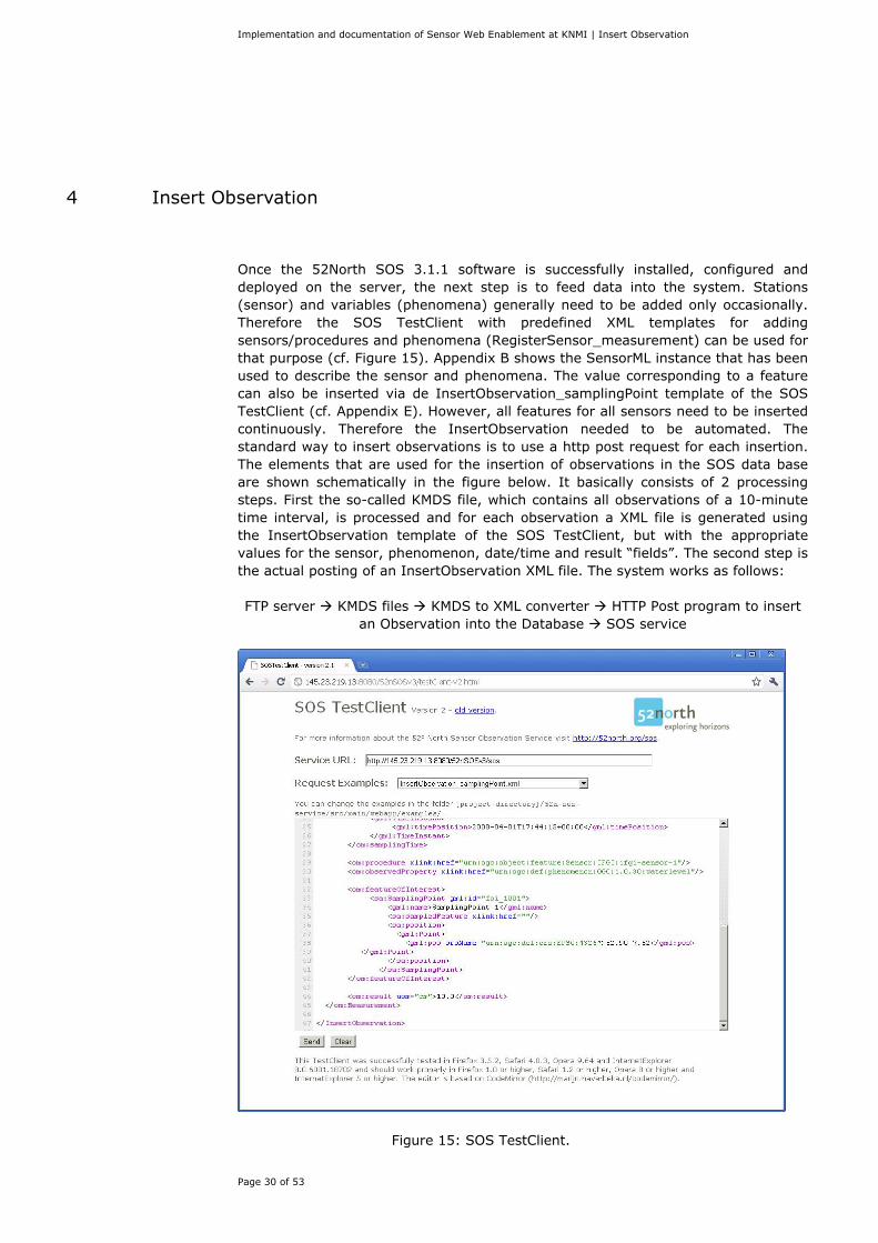
Once the 52North SOS 3.1.1 software is successfully installed, configured and deployed on the server, the next step is to feed data into the system. Stations (sensor) and variables (phenomena) generally need to be added only occasionally. Therefore the SOS TestClient with predefined XML templates for adding sensors/procedures and phenomena (RegisterSensor_measurement) can be used for that purpose (cf. Figure 15). Appendix B shows the SensorML instance that has been used to describe the sensor and phenomena. The value corresponding to a feature can also be inserted via de InsertObservation_samplingPoint template of the SOS TestClient (cf. Appendix E). However, all features for all sensors need to be inserted continuously. Therefore the InsertObservation needed to be automated. The standard way to insert observations is to use a http post request for each insertion. The elements that are used for the insertion of observations in the SOS data base are shown schematically in the figure below. It basically consists of 2 processing steps. First the so-called KMDS file, which contains all observations of a 10-minute time interval, is processed and for each observation a XML file is generated using the InsertObservation template of the SOS TestClient, but with the appropriate values for the sensor, phenomenon, date/time and result “fields”. The second step is the actual posting of an InsertObservation XML file. The system works as follows: FTP server KMDS files KMDS to XML converter HTTP Post program to insert
an Observation into the Database SOS service
Figure 15: SOS TestClient.
Implementation and documentation of Sensor Web Enablement at KNMI | Insert Observation
Page 31 of 53
The data acquisitions of the sensors are stored in KMDS files received by FTP. These files are compound of text lines, where each line corresponds to one data acquisition. The lines appear in the file according to the syntax:
Station, Date, Time, Group, Variable, Value, Quality, Thereby, a fragment of one of this KMDS files could have the form: (...) 06239, 20070330, 0950, 10Min, dd, 54.7, 0, 06239, 20070330, 0950, 10Min, ff, 6.207475, 0, 06239, 20070330, 0950, 10Min, pg, 0, 0, 06239, 20070330, 0950, 10Min, pr, 0, 0, 06239, 20070330, 0950, 10Min, rh, 95, 0, (...) It is easy to realize that the information regarding stations and measured features are encoded in this KMDS files. Additional information and the terms used to encode the stations and features can be found in Appendix C. The data contained in the KMDS files are not ready to directly be put into the database because it doesn't suit the format that it is able to receive. Therefore, some intermediate steps are necessary before being able to insert the information into the database. Those steps consist in two java scripts: kmds2xml.java and PostXML.java.
4.1 kmds2xml This first script has two input files, a KMDS file and a XML template file, and n output files, where n is the number of lines contained in the KMDS file. The usage is:
> java kmds2xml <xml_template.xml> <kmds_input_file.dat> Basically, this script opens the KMDS file and reads sequentially each line. When it finds a new line, it parses it and saves the elements -station, date, time, group, variable, value, quality- to use them later. Then, it parses the template XML file and searches the nodes to edit. The value of these nodes is set using the info obtained from the KMDS. Finally, it creates a new XML file, similar to the template but with the information from the KMDS file inserted at the corresponding nodes. Thereby, it creates a number of edited XML files equal to the number of lines that the KMDS file has, each one with the information of one data acquisition. For being able to know the correspondent unit for each feature of interest, a Map<String, String> has been used. Thereby, when the script reads the code of the feature of interest, it searches in the map the equivalent unit. For example, if it receives “dd”, it will get “degree” from the map. The kmds2xml.java script furthermore inserts the procedure and feature of interest corresponding to the Station and Variable name found in the KMDS file, sets the proper data and time and inserts the value of the observation.
Implementation and documentation of Sensor Web Enablement at KNMI | Insert Observation
Page 32 of 53
No additional packages are required to run this script. The CLASSPATH environment variable in the .bashrc file needed to be set so that it points to the jar files of the packages used. export JAVA_HOME=/usr/lib/jvm/java-6-sun export PATH=$JAVA_HOME/bin:$PATH export CLASSPATH=/home/knmi:/var/lib/tomcat6/webapps/52nSOSv3/WEB-INF/lib/52n-sos-ogc-3.1.jar:/home/knmi/52n-sos/52n-sos-service/target/52nSOSv3/WEB-INF/lib/joda-time-1.6.jar The code of the kmds2xml.java script can be found in Appendix D. The xml_template.xml, which in fact is the InsertObservation_samplingPoint.xml from the 52North TestClient, can be found in Appendix E.
4.2 PostXML As it is previously mentioned, the kmds2xml script creates XML files with the information of each data acquisition. This XML file suits the insert_observation format of the SOS service. The PostXML script just gets one XML file, creates the connection to the SOS service and executes an HTTP POST request to the URL used by the SOS:
http://localhost:8080/52nSOSv3/sos The code of the PostXML.java script can be found in Appendix F. In order to run the PostXML script, the installation of some additional packages is required.
4.2.1 HttpClient HttpClient21 provides a package that implements the client side of the HTTP standards and recommendations. This package can be downloaded from the URL:
http://hc.apache.org/downloads.cgi
In our case, the installation folder is:
/home/knmi/maven2repository/
Once downloaded and unzipped, to compile and test the components the command used is:
> mvn test
The following command builds the JAR packages:
> mvn package
The resultant packages can be found in the target folders of their respective modules:
Implementation and documentation of Sensor Web Enablement at KNMI | Insert Observation
Page 33 of 53
httpclient/target/httpclient-<VERSION>.jar httpmime/target/httpmime-<VERSION>.jar httpclient-osgi/target/org.apache.httpcomponents.httpclient_<VERSION>.jar
Where <VERSION> is the release version, in this case 4.1.1.
This command generates the javadoc:
> mvn javadoc:aggregate
And this one generates the tutorial in html and pdf formats:
> mvn docbkx:generate-pdf docbkx:generate-html
Next step is to build the distribution assemblies:
> mvn package assembly:assembly
Finally, to fix the archive files so the source files have the correct EOL settings it is necessary to run the command:
> mvn antrun:run
4.2.2 HttpCore HttpCore22 is a set of low level HTTP transport components that can be used to build custom client and server side HTTP services with a minimal footprint. This package can be downloaded from the URL:
http://hc.apache.org/downloads.cgi The installation folder and the commands used to install HttpCore are the same than the previously mentioned when installing HttpClient. The only difference is when running the command:
> mvn package The resultant packages have the
httpcore/target/httpcore-<VERSION>.jar httpcore-nio/target/httpcore-nio-<VERSION>.jar httpcore-osgi/target/org.apache.httpcomponents.httpcore_<VERSION>.jar
Where <VERSION> is the release version, in this case 4.1.
4.2.3 Commons-logging The Logging package23 is an ultra-thin bridge between different logging implementations. A library that uses the commons-logging API can be used with any logging implementation at runtime.
Implementation and documentation of Sensor Web Enablement at KNMI | Insert Observation
Page 34 of 53
This package can be downloaded from the URL:
http://commons.apache.org/logging/download_logging.cgi But in our case it was already installed because of the Maven installation. Finally, to run this script it is also necessary to set again the CLASSPATH environment variable in the .bashrc file so that it points to the new jar files installed:
export JAVA_HOME=/usr/lib/jvm/java-6-sun export PATH=$JAVA_HOME/bin:$PATH export CLASSPATH=/home/knmi/maven2repository/httpcomponents-client-4.1.1/httpclient/target/httpclient-4.1.1.jar:/home/knmi/maven2repository/httpcomponents-core-4.1/httpcore/target/httpcore-4.1.jar:/home/knmi:/home/knmi/maven2repository/commons-logging/commons-logging/1.1.1/commons-logging-1.1.1.jar:/var/lib/tomcat6/webapps/52nSOSv3/WEB-INF/lib/52n-sos-ogc-3.1.jar:/home/knmi/52n-sos/52n-sos-service/target/52nSOSv3/WEB-INF/lib/joda-time-1.6.jar
Note: the CLASSPATH environment variable also points to /home/knmi because it is the folder where PostXML.java and kmds2xml.java are stored.
Implementation and documentation of Sensor Web Enablement at KNMI | Conclusions and recommendations
Page 35 of 53
5 Conclusions and recommendations
This report describes the installation of the 52N software of the SOS service of current SWE software suite on a Linux platform. In addition, the building blocks for the insertion of sensor data into the database of the SOS service are given. Hence the report enables KNMI to easily install and feed the recent SOS service in their development environment. The relationship between the KMDS stations and variables and the SOS procedures and phenomena and their units are hardcoded in the current kmds2xml.java script. It is recommended that the kmds2xml.java is adapted so that these relationships can be read from a configuration file so that it can easily be modified or extended without changes to the script.
Implementation and documentation of Sensor Web Enablement at KNMI | References
Page 36 of 53
6 References
1 RGI-189 Sensoren als databronnen aan de geo-informatie infrastructuur. http://rgi.max.nl/?page=projects&sub=details&id=134 2 RGI-189 WP6: SWE in meteorologische waarnemingssystemen. http://www.knmi.nl/~wauben/HIM/SWE KNMI evaluatie v3.pdf 3 http://en.wikipedia.org/wiki/Interoperability. 4 Sensor Web Enablement: Overview and High Level Architecture, OGC 07-165. 5 Sensor Web Enablement Intro, Mike Bolis. September 2008. 6 Sensor Observation Service, OGC 06-009r6. 7 Sensor Alert Service Candidate Implementation Specification, OGC 06-028r3. 8 Sensor Planning Service Implementation Specification, OGC 05-089r3. 9 Web Notification Service Implementation Specification, OGC 06-095. 10 Observations and Measurements, OGC 05-087r3. 11 Sensor Model Language (SensorML) Implementation Specification, OGC 07-000. 12 Transducer Markup Language Implementation Specification, OGC 06-010r2. 13 http://www.postgresql.org/about/ 14 http://en.wikipedia.org/wiki/Apache_Tomcat 15 http://openjdk.java.net/ 16 http://maven.apache.org/ 17 http://en.wikipedia.org/wiki/Eclipse_(software) 18 http://52north.org/communities/sensorweb/sos/index.html 19 http://52north.org/communities/sensorweb/sos/design.html 20 https://wiki.52north.org/bin/view/Sensornet/SosDataModeling 21 http://hc.apache.org/httpcomponents-client-ga/ 22 http://hc.apache.org/httpcomponents-core-ga/index.html 23 http://commons.apache.org/logging/
Implementation and documentation of Sensor Web Enablement at KNMI | Appendix A
Page 37 of 53
Appendix A
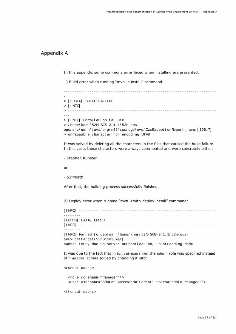
In this appendix some commons error faced when installing are presented. 1) Build error when running “mvn -e install” command: -----------------------------------------------------------------------
-
> [ERROR] BUILD FAILURE
> [INFO]
> ---------------------------------------------------------------------
---
> [INFO] Compilation failure
> /home/knmi/52N-SOS-3.1.1/52n-sos-
ogc/src/main/java/org/n52/sos/ogc/ows/OwsExceptionReport.java:[108,7]
> unmappable character for encoding UTF8
It was solved by deleting all the characters in the files that caused the build failure. In this case, those characters were always commented and were concretely either: - Stephan Kϋnster. or - 52°North. After that, the building process successfully finished. 2) Deploy error when running “mvn -Pwith-deploy install” command: [INFO] ----------------------------------------------------------------
--------
[ERROR] FATAL ERROR
[INFO] ----------------------------------------------------------------
--------
[INFO] Failed to deploy [/home/knmi/52N-SOS-3.1.1/52n-sos-
service/target/52nSOSv3.war]
cannot retry due to server authentication, in streaming mode It was due to the fact that in tomcat-users.xml the admin role was specified instead of manager. It was solved by changing it into: <tomcat-users>
<role rolename="manager"/>
<user username="admin" password="tomcat" roles="admin,manager"/>
</tomcat-users>
Implementation and documentation of Sensor Web Enablement at KNMI | Appendix A
Page 38 of 53
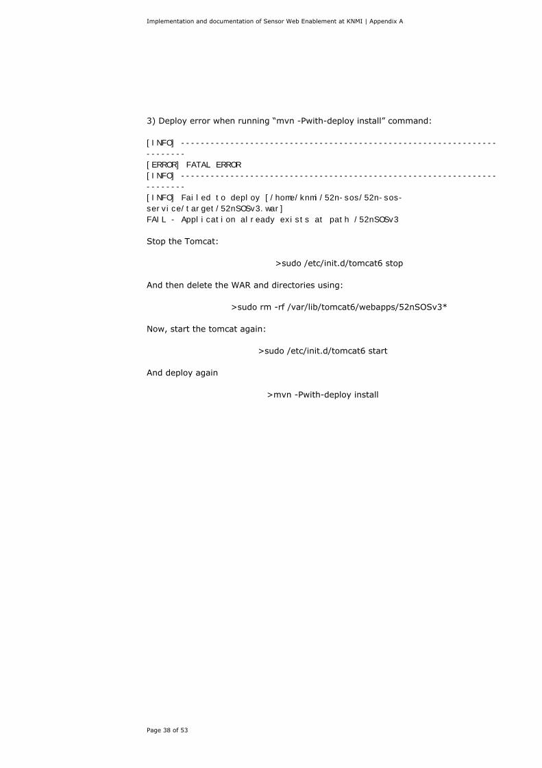
3) Deploy error when running “mvn -Pwith-deploy install” command: [INFO] ----------------------------------------------------------------
--------
[ERROR] FATAL ERROR
[INFO] ----------------------------------------------------------------
--------
[INFO] Failed to deploy [/home/knmi/52n-sos/52n-sos-
service/target/52nSOSv3.war]
FAIL - Application already exists at path /52nSOSv3 Stop the Tomcat:
>sudo /etc/init.d/tomcat6 stop And then delete the WAR and directories using:
>sudo rm -rf /var/lib/tomcat6/webapps/52nSOSv3* Now, start the tomcat again:
>sudo /etc/init.d/tomcat6 start And deploy again
>mvn -Pwith-deploy install
Implementation and documentation of Sensor Web Enablement at KNMI | Appendix B
Page 39 of 53
Appendix B
This SensorML instance defines the information regarding the sensor itself. <?xml version="1.0" encoding="ISO-8859-1"?> <sml:SensorML xsi:schemaLocation="http://www.opengis.net/sensorML/1.0.1 http://schemas.opengis.net/sensorML/1.0.1/sensorML.xsd" version="1.0.1" xmlns="http://www.opengis.net/sensorML/1.0.1" xmlns:swe="http://www.opengis.net/swe/1.0.1" xmlns:xlink="http://www.w3.org/1999/xlink" xmlns:xsi="http://www.w3.org/2001/XMLSchema-instance" xmlns:sml="http://www.opengis.net/sensorML/1.0.1" xmlns:gml="http://www.opengis.net/gml"> <sml:member> <sml:System xmlns:xsi="http://www.w3.org/2001/XMLSchema-instance"> <!--sml:identification element must contain the ID of the sensor--> <sml:identification> <sml:IdentifierList> <sml:identifier> <sml:Term> <sml:value> urn:ogc:object:sensor:KNMI:procedure06260 </sml:value> </sml:Term> </sml:identifier> </sml:IdentifierList> </sml:identification> <!-- sml:capabilities element has to contain status and mobility information --> <sml:capabilities> <swe:SimpleDataRecord> <!-- status indicates, whether sensor is collecting data at the moment (true) or not (false) --> <swe:field name="status"> <swe:Boolean> <swe:value>true</swe:value> </swe:Boolean> </swe:field> <!-- status indicates, whether sensor is mobile (true) or fixed (false) --> <swe:field name="mobile"> <swe:Boolean> <swe:value>false</swe:value> </swe:Boolean> </swe:field> </swe:SimpleDataRecord> </sml:capabilities> <!-- last measured position of sensor -->
Implementation and documentation of Sensor Web Enablement at KNMI | Appendix B
Page 40 of 53
<sml:position name="sensorPosition"> <swe:Position referenceFrame="urn:ogc:def:crs:EPSG:4326"> <swe:location> <swe:Vector gml:id="STATION_LOCATION"> <swe:coordinate name="northing"> <swe:Quantity axisID="y"> <swe:uom code="degree" /> <swe:value>52.10</swe:value> </swe:Quantity> </swe:coordinate> <swe:coordinate name="easting"> <swe:Quantity axisID="x"> <swe:uom code="degree" /> <swe:value>5.18</swe:value> </swe:Quantity> </swe:coordinate> <swe:coordinate name="altitude"> <swe:Quantity axisID="z"> <swe:uom code="m" /> <swe:value>2.00</swe:value> </swe:Quantity> </swe:coordinate> </swe:Vector> </swe:location> </swe:Position> </sml:position> <!-- list containing the input phenomena for this sensor system --> <sml:inputs> <sml:InputList> <sml:input name="windDirection"> <swe:ObservableProperty definition="urn:ogc:def:phenomenon:OGC:1.0.30:windDirection" /> </sml:input> <sml:input name="windSpeed"> <swe:ObservableProperty definition="urn:ogc:def:phenomenon:OGC:1.0.30:windSpeed" /> </sml:input> <sml:input name="precipitation"> <swe:ObservableProperty definition="urn:ogc:def:phenomenon:OGC:1.0.30:precipitation" /> </sml:input> <sml:input name="globalRadiation"> <swe:ObservableProperty definition="urn:ogc:def:phenomenon:OGC:1.0.30:globalRadiation" /> </sml:input> <sml:input name="relativeHumidity"> <swe:ObservableProperty definition="urn:ogc:def:phenomenon:OGC:1.0.30:relativeHumidity" />
Implementation and documentation of Sensor Web Enablement at KNMI | Appendix B
Page 41 of 53
</sml:input> <sml:input name="ambientAirTemperature"> <swe:ObservableProperty definition="urn:ogc:def:phenomenon:OGC:1.0.30:ambientAirTemperature" /> </sml:input> </sml:InputList> </sml:inputs> <!--list containing the output phenomena of this sensor system; ATTENTION: these phenomena are parsed and inserted into the database; they have to contain offering elements to determine the correct offering for the sensors and measured phenomena --> <sml:outputs> <sml:OutputList> <sml:output name="dd"> <swe:Quantity definition="urn:ogc:def:phenomenon:OGC:1.0.30:windDirection"> <gml:metaDataProperty> <offering> <id>WIND_DIRECTION</id> <name>10-minute averaged wind direction</name> </offering> </gml:metaDataProperty> <swe:uom code="degrees" /> </swe:Quantity> </sml:output> <sml:output name="ff"> <swe:Quantity definition="urn:ogc:def:phenomenon:OGC:1.0.30:windSpeed"> <gml:metaDataProperty> <offering> <id>WIND_SPEED</id> <name>10-minute averaged wind speed (reduced to 10m)</name> </offering> </gml:metaDataProperty> <swe:uom code="m/sec" /> </swe:Quantity> </sml:output> <sml:output name="dr"> <swe:Quantity definition="urn:ogc:def:phenomenon:OGC:1.0.30:durationRainGauge"> <gml:metaDataProperty> <offering> <id>DURATION_RAIN_GAUGE</id> <name>10-minute precipitation duration</name> </offering> </gml:metaDataProperty> <swe:uom code="sec" /> </swe:Quantity> </sml:output>
Implementation and documentation of Sensor Web Enablement at KNMI | Appendix B
Page 42 of 53
<sml:output name="rg"> <swe:Quantity definition="urn:ogc:def:phenomenon:OGC:1.0.30:intensityRainGauge"> <gml:metaDataProperty> <offering> <id>INTENSITY_RAIN_GAUGE</id> <name>10-minute averaged precipitation intensity</name> </offering> </gml:metaDataProperty> <swe:uom code="mm/h" /> </swe:Quantity> </sml:output> <sml:output name="pr"> <swe:Quantity definition="urn:ogc:def:phenomenon:OGC:1.0.30:precipitationDuration"> <gml:metaDataProperty> <offering> <id>PRECIPITATION_DURATION</id> <name>10-minute precipitation duration</name> </offering> </gml:metaDataProperty> <swe:uom code="sec" /> </swe:Quantity> </sml:output> <sml:output name="pg"> <swe:Quantity definition="urn:ogc:def:phenomenon:OGC:1.0.30:precipitationIntensity"> <gml:metaDataProperty> <offering> <id>PRECIPITATION_INTENSITY</id> <name>10-minute averaged precipitation intensity</name> </offering> </gml:metaDataProperty> <swe:uom code="mm/h" /> </swe:Quantity> </sml:output> <sml:output name="gg"> <swe:Quantity definition="urn:ogc:def:phenomenon:OGC:1.0.30:globalSolarRadiation"> <gml:metaDataProperty> <offering> <id>GLOBAL_SOLAR_RADIATION</id> <name>10-minute global radiation</name> </offering> </gml:metaDataProperty> <swe:uom code="w/m2" /> </swe:Quantity> </sml:output> <sml:output name="rh"> <swe:Quantity
Implementation and documentation of Sensor Web Enablement at KNMI | Appendix B
Page 43 of 53
definition="urn:ogc:def:phenomenon:OGC:1.0.30:relativeHumidity"> <gml:metaDataProperty> <offering> <id>RELATIVE_HUMIDITY</id> <name>10-minute relative humidity</name> </offering> </gml:metaDataProperty> <swe:uom code="percent" /> </swe:Quantity> </sml:output> <sml:output name="at"> <swe:Quantity definition="urn:ogc:def:phenomenon:OGC:1.0.30:airTemperature"> <gml:metaDataProperty> <offering> <id>AIR_TEMPERATURE</id> <name>10-minute ambient air temperature</name> </offering> </gml:metaDataProperty> <swe:uom code="degrees celsius" /> </swe:Quantity> </sml:output> </sml:OutputList> </sml:outputs> <!-- description of components of this sensor system; these are currently not used by the 52N SOS <sml:components> <sml:ComponentList> <sml:component name="water sensor"> <sml:Component> <sml:identification> <sml:IdentifierList> <sml:identifier> <sml:Term definition="urn:ogc:def:identifier:OGC:uniqueID"> <sml:value> urn:ogc:object:feature:Sensor:water_level_sensor </sml:value> </sml:Term> </sml:identifier> </sml:IdentifierList> </sml:identification> <sml:inputs> <sml:InputList> <sml:input name="waterlevel"> <swe:ObservableProperty definition="urn:ogc:def:phenomenon:OGC:1.0.30:waterlevel" /> </sml:input> </sml:InputList> </sml:inputs>
Implementation and documentation of Sensor Web Enablement at KNMI | Appendix B
Page 44 of 53
<sml:outputs> <sml:OutputList> <sml:output name="waterlevel"> <swe:Quantity definition="urn:ogc:def:phenomenon:OGC:1.0.30:waterlevel"> <swe:uom code="cm" /> </swe:Quantity> </sml:output> </sml:OutputList> </sml:outputs> </sml:Component> </sml:component> </sml:ComponentList> </sml:components>--> </sml:System> </sml:member> </sml:SensorML> Note: It is necessary that the names of the documents are the same as the last part of their URNs. These URNs correspond to the procedure Ids in our data model.
Implementation and documentation of Sensor Web Enablement at KNMI | Appendix C
Page 45 of 53
Appendix C
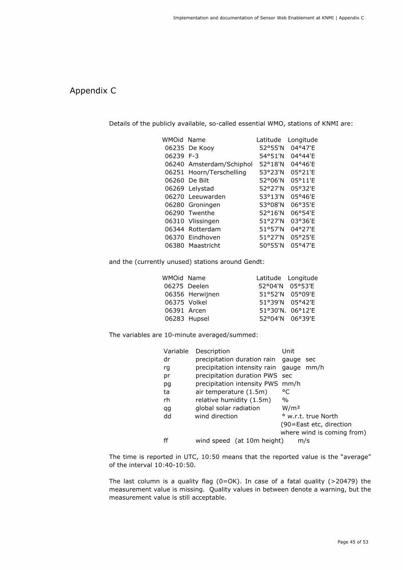
Details of the publicly available, so-called essential WMO, stations of KNMI are:
WMOid Name Latitude Longitude 06235 De Kooy 52°55'N 04°47'E 06239 F-3 54°51'N 04°44'E 06240 Amsterdam/Schiphol 52°18'N 04°46'E 06251 Hoorn/Terschelling 53°23'N 05°21'E 06260 De Bilt 52°06'N 05°11'E 06269 Lelystad 52°27'N 05°32'E 06270 Leeuwarden 53°13'N 05°46'E 06280 Groningen 53°08'N 06°35'E 06290 Twenthe 52°16'N 06°54'E 06310 Vlissingen 51°27'N 03°36'E 06344 Rotterdam 51°57'N 04°27'E 06370 Eindhoven 51°27'N 05°25'E 06380 Maastricht 50°55'N 05°47'E
and the (currently unused) stations around Gendt:
WMOid Name Latitude Longitude 06275 Deelen 52°04'N 05°53’E 06356 Herwijnen 51°52'N 05°09'E 06375 Volkel 51°39'N 05°42’E 06391 Arcen 51°30'N. 06°12'E 06283 Hupsel 52°04'N 06°39'E
The variables are 10-minute averaged/summed:
Variable Description Unit dr precipitation duration rain gauge sec rg precipitation intensity rain gauge mm/h pr precipitation duration PWS sec pg precipitation intensity PWS mm/h ta air temperature (1.5m) °C rh relative humidity (1.5m) % qg global solar radiation W/m² dd wind direction ° w.r.t. true North
(90=East etc, direction where wind is coming from)
ff wind speed (at 10m height) m/s The time is reported in UTC, 10:50 means that the reported value is the “average” of the interval 10:40-10:50. The last column is a quality flag (0=OK). In case of a fatal quality (>20479) the measurement value is missing. Quality values in between denote a warning, but the measurement value is still acceptable.
Implementation and documentation of Sensor Web Enablement at KNMI | Appendix D
Page 46 of 53
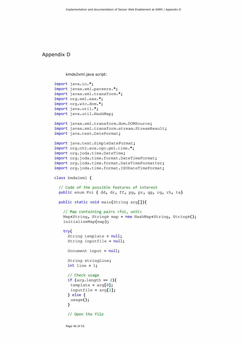
Appendix D
kmds2xml.java script:
import java.io.*; import javax.xml.parsers.*; import javax.xml.transform.*; import org.xml.sax.*; import org.w3c.dom.*; import java.util.*; import java.util.HashMap; import javax.xml.transform.dom.DOMSource; import javax.xml.transform.stream.StreamResult; import java.text.DateFormat; import java.text.SimpleDateFormat; import org.n52.sos.ogc.gml.time.*; import org.joda.time.DateTime; import org.joda.time.format.DateTimeFormat; import org.joda.time.format.DateTimeFormatter; import org.joda.time.format.ISODateTimeFormat; class kmds2xml { // Code of the possible features of interest public enum Foi { dd, dr, ff, pg, pr, qg, rg, rh, ta} public static void main(String arg[]){ // Map containing pairs <foi, unit> Map<String, String> map = new HashMap<String, String>(); initializeMap(map); try{ String template = null; String inputfile = null; Document input = null; String stringLine; int line = 1; // Check usage if (arg.length == 2){ template = arg[0]; inputfile = arg[1]; } else { usage(); } // Open the file
Implementation and documentation of Sensor Web Enablement at KNMI | Appendix D
Page 47 of 53
FileInputStream fstream = new FileInputStream(inputfile); DataInputStream in = new DataInputStream(fstream); BufferedReader br = new BufferedReader(new InputStreamReader(in)); //Read file line by line and create a xml file for each one //Files created are called result<i>.xml, when i is the correspondent line //in the inputfile.dat while ((stringLine = br.readLine()) != null) { //Parse the line Scanner s = new Scanner(stringLine).useDelimiter("\\s*, \\s*"); String proc = "urn:ogc:object:sensor:KNMI:procedure"+s.next(); String date1 = s.next(); String date2 = s.next(); String dateString = date1 + date2; DateFormat df = new SimpleDateFormat("yyyyMMDDHHmm"); Date date = df.parse(dateString); DateTime datetime = new DateTime(date); String tenmin = s.next(); String foiString = s.next(); // Get unit String unit = map.get(foiString); try { foiString = initializeFoi(foiString); }catch(Exception ex){ System.out.println("Unknown feature of interest");; } Double measValue = s.nextDouble(); String qualityflag = s.next(); s.close(); DocumentBuilderFactory dbf = DocumentBuilderFactory.newInstance(); dbf.setNamespaceAware(true); dbf.setIgnoringElementContentWhitespace(true); try { DocumentBuilder builder = dbf.newDocumentBuilder(); builder.setErrorHandler(new MyErrorHandler()); InputSource is = new InputSource(template); input = builder.parse(is); } catch (SAXException e) { System.exit(1); } catch (ParserConfigurationException e) { System.err.println(e); System.exit(1); } catch (IOException e) { System.err.println(e); System.exit(1);
Implementation and documentation of Sensor Web Enablement at KNMI | Appendix D
Page 48 of 53
} fileCreator fc = new fileCreator(); fc.create(input, line, datetime, measValue, proc, foiString, unit); line++; } in.close(); }catch (Exception e){ System.err.println(e); System.exit(1); } } private static void usage() { System.err.println("Usage: java b <xml_template.xml> <input_file.dat>"); System.exit(1); } public static String initializeFoi (String f){ switch(Foi.valueOf(f)) { case dd: return "urn:ogc:def:phenomenon:windDirection"; case dr: return "urn:ogc:def:phenomenon:durationRainGauge"; case ff: return "urn:ogc:def:phenomenon:windSpeed"; case pg: return "urn:ogc:def:phenomenon:precipitationIntensity"; case pr: return "urn:ogc:def:phenomenon:precipitationDuration"; case qg: return "urn:ogc:def:phenomenon:globalSolarRadiation"; case rg: return "urn:ogc:def:phenomenon:intensityRainGauge"; case rh: return "urn:ogc:def:phenomenon:relativeHumidity"; case ta: return "urn:ogc:def:phenomenon:airTemperature"; default: // Unknown feature of interest. Return the code. return f; } } public static void initializeMap(Map<String, String> map){ map.put("dd", "degree"); map.put("dr", "sec"); map.put("ff", "m_per_sec"); map.put("pg", "mm_per_h"); map.put("pr", "sec"); map.put("qg", "watt_per_squaremeter"); map.put("rg", "mm_per_h"); map.put("rh", "percent"); map.put("ta", "degree_celsius"); }
Implementation and documentation of Sensor Web Enablement at KNMI | Appendix D
Page 49 of 53
} class fileCreator { Document output = null; boolean next_time = false; boolean next_value = false; boolean next_sensor = false; public void create(Document doc, int i, DateTime datetime, double value, String proc, String foi, String unit) { loop((Node)doc, datetime, value, proc, foi, unit); try{ //write the content into a xml file TransformerFactory transformerFactory = TransformerFactory.newInstance(); Transformer transformer = transformerFactory.newTransformer(); DOMSource source = new DOMSource(doc); StreamResult result = new StreamResult(new File("result"+Integer.toString(i)+".xml")); transformer.transform(source, result); }catch(TransformerException tfe){ tfe.printStackTrace(); } } private void loop(Node node, DateTime datetime, double value, String proc, String foi, String unit) { NamedNodeMap atts = null; if(node.getNodeName().equals("AssignedSensorId")){ next_sensor = true; }else if(node.getNodeName().equals("gml:timePosition")){ next_time = true; }else if(node.getNodeName().equals("om:procedure")){ atts = node.getAttributes(); for (int j=0; j<atts.getLength(); j++) { Attr attr = (Attr)atts.item(j); attr.setValue(proc); } }else if(node.getNodeName().equals("om:observedProperty")){ atts = node.getAttributes(); for (int j=0; j<atts.getLength(); j++) { Attr attr = (Attr)atts.item(j); attr.setValue(foi); } }else if(node.getNodeName().equals("om:result")){ next_value = true; atts = node.getAttributes(); for (int j=0; j<atts.getLength(); j++) {
Implementation and documentation of Sensor Web Enablement at KNMI | Appendix D
Page 50 of 53
Attr attr = (Attr)atts.item(j); attr.setValue(unit); } }else if ((next_sensor == true)){ node.setNodeValue(proc); next_sensor = false; }else if ((next_time == true)){ DateTimeFormatter dtf = ISODateTimeFormat.dateTimeNoMillis(); node.setNodeValue(datetime.toString(dtf)); next_time = false; }else if ((next_value == true)){ node.setNodeValue(Double.toString(value)); next_value = false; } NodeList list = node.getChildNodes(); for(int i=0; i<list.getLength(); i++){ loop(list.item(i), datetime, value, proc, foi, unit); } } } class MyErrorHandler implements ErrorHandler { public void warning(SAXParseException e) throws SAXException { show("Warning", e); throw (e); } public void error(SAXParseException e) throws SAXException { show("Error", e); throw (e); } public void fatalError(SAXParseException e) throws SAXException { show("Fatal Error", e); throw (e); } private void show(String type, SAXParseException e) { System.out.println(type + ": " + e.getMessage()); System.out.println("Line " + e.getLineNumber() + " Column " + e.getColumnNumber()); System.out.println("System ID: " + e.getSystemId()); } }
Implementation and documentation of Sensor Web Enablement at KNMI | Appendix E
Page 51 of 53
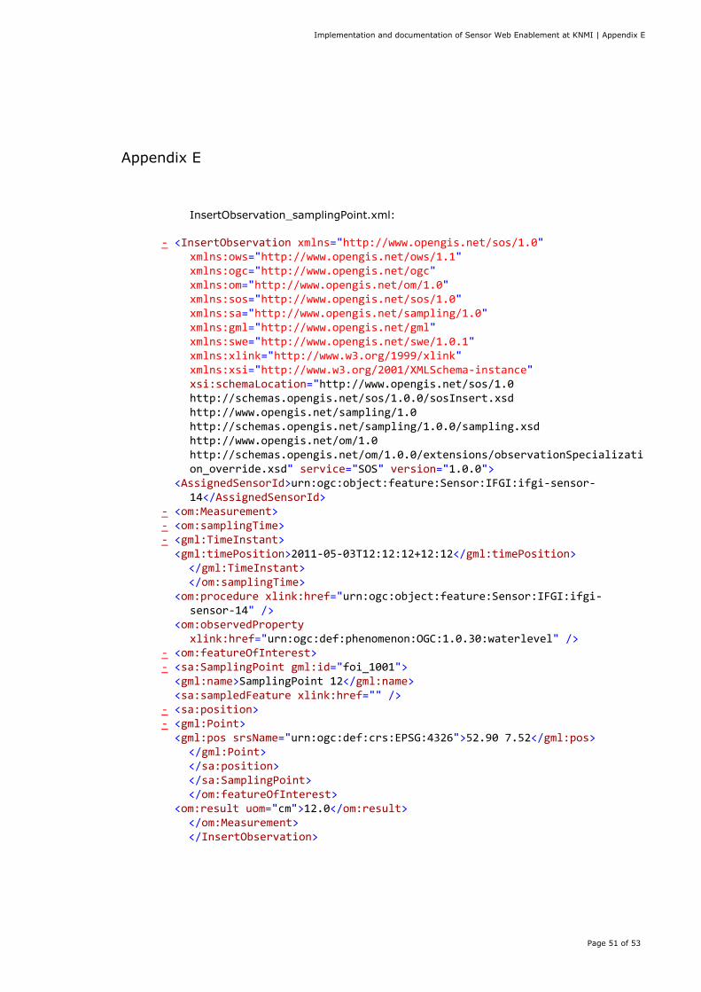
Appendix E
InsertObservation_samplingPoint.xml:
- <InsertObservation xmlns="http://www.opengis.net/sos/1.0" xmlns:ows="http://www.opengis.net/ows/1.1" xmlns:ogc="http://www.opengis.net/ogc" xmlns:om="http://www.opengis.net/om/1.0" xmlns:sos="http://www.opengis.net/sos/1.0" xmlns:sa="http://www.opengis.net/sampling/1.0" xmlns:gml="http://www.opengis.net/gml" xmlns:swe="http://www.opengis.net/swe/1.0.1" xmlns:xlink="http://www.w3.org/1999/xlink" xmlns:xsi="http://www.w3.org/2001/XMLSchema-instance" xsi:schemaLocation="http://www.opengis.net/sos/1.0 http://schemas.opengis.net/sos/1.0.0/sosInsert.xsd http://www.opengis.net/sampling/1.0 http://schemas.opengis.net/sampling/1.0.0/sampling.xsd http://www.opengis.net/om/1.0 http://schemas.opengis.net/om/1.0.0/extensions/observationSpecialization_override.xsd" service="SOS" version="1.0.0">
<AssignedSensorId>urn:ogc:object:feature:Sensor:IFGI:ifgi-sensor-14</AssignedSensorId>
- <om:Measurement> - <om:samplingTime> - <gml:TimeInstant> <gml:timePosition>2011-05-03T12:12:12+12:12</gml:timePosition>
</gml:TimeInstant> </om:samplingTime>
<om:procedure xlink:href="urn:ogc:object:feature:Sensor:IFGI:ifgi-sensor-14" />
<om:observedProperty xlink:href="urn:ogc:def:phenomenon:OGC:1.0.30:waterlevel" />
- <om:featureOfInterest> - <sa:SamplingPoint gml:id="foi_1001"> <gml:name>SamplingPoint 12</gml:name> <sa:sampledFeature xlink:href="" /> - <sa:position> - <gml:Point> <gml:pos srsName="urn:ogc:def:crs:EPSG:4326">52.90 7.52</gml:pos>
</gml:Point> </sa:position> </sa:SamplingPoint> </om:featureOfInterest>
<om:result uom="cm">12.0</om:result> </om:Measurement> </InsertObservation>
Implementation and documentation of Sensor Web Enablement at KNMI | Appendix F
Page 52 of 53
Appendix F
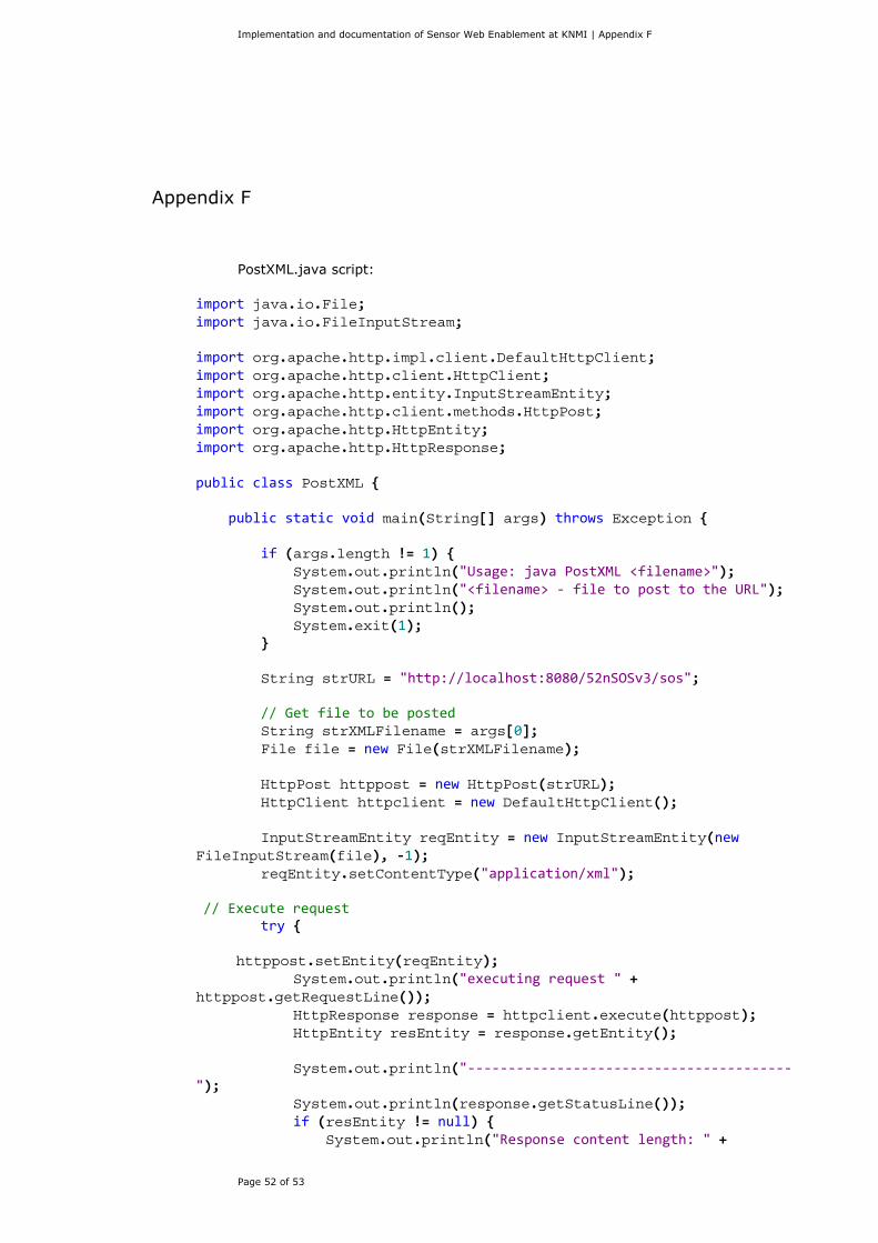
PostXML.java script:
import java.io.File; import java.io.FileInputStream; import org.apache.http.impl.client.DefaultHttpClient; import org.apache.http.client.HttpClient; import org.apache.http.entity.InputStreamEntity; import org.apache.http.client.methods.HttpPost; import org.apache.http.HttpEntity; import org.apache.http.HttpResponse; public class PostXML { public static void main(String[] args) throws Exception { if (args.length != 1) { System.out.println("Usage: java PostXML <filename>"); System.out.println("<filename> - file to post to the URL"); System.out.println(); System.exit(1); } String strURL = "http://localhost:8080/52nSOSv3/sos"; // Get file to be posted String strXMLFilename = args[0]; File file = new File(strXMLFilename); HttpPost httppost = new HttpPost(strURL); HttpClient httpclient = new DefaultHttpClient(); InputStreamEntity reqEntity = new InputStreamEntity(new FileInputStream(file), -1); reqEntity.setContentType("application/xml"); // Execute request try { httppost.setEntity(reqEntity); System.out.println("executing request " + httppost.getRequestLine()); HttpResponse response = httpclient.execute(httppost); HttpEntity resEntity = response.getEntity(); System.out.println("----------------------------------------"); System.out.println(response.getStatusLine()); if (resEntity != null) { System.out.println("Response content length: " +
Implementation and documentation of Sensor Web Enablement at KNMI | Appendix F
Page 53 of 53
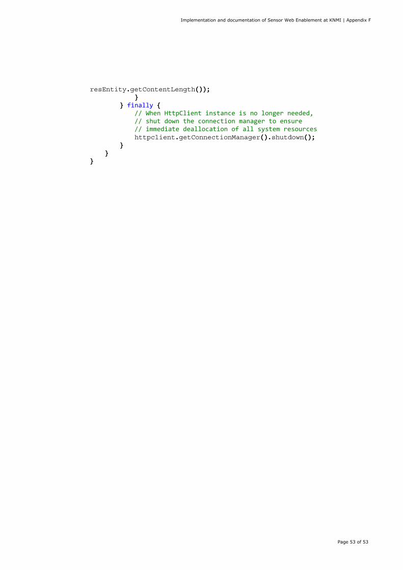
resEntity.getContentLength()); } } finally { // When HttpClient instance is no longer needed, // shut down the connection manager to ensure // immediate deallocation of all system resources httpclient.getConnectionManager().shutdown(); } } }

A complete list of all KNMI-publications (1854 – present) can be found on our website www.knmi.nl/knmi-library/knmipub_en.html
The most recent reports are available as a PDF on this site.