Embed Size (px)
Citation preview
2nd Qtr 2009 ■ Page 5
Implementing Oracle Grid: A Successful Customer Case Study
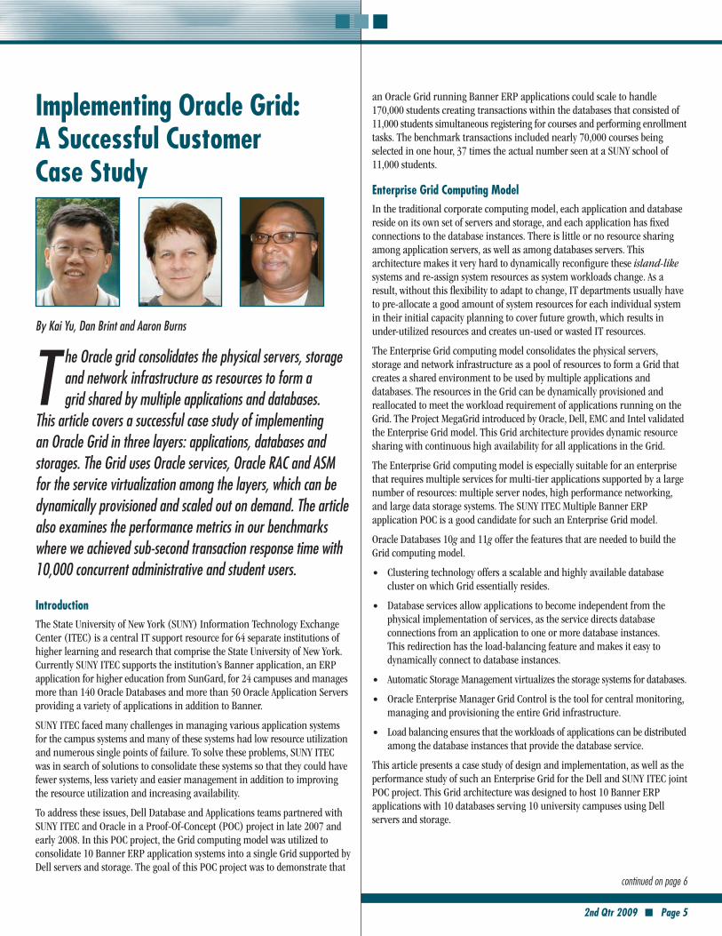
By Kai Yu, Dan Brint and Aaron Burns
T he Oracle grid consolidates the physical servers, storage and network infrastructure as resources to form a grid shared by multiple applications and databases.
This article covers a successful case study of implementing an Oracle Grid in three layers: applications, databases and storages. The Grid uses Oracle services, Oracle RAC and ASM for the service virtualization among the layers, which can be dynamically provisioned and scaled out on demand. The article also examines the performance metrics in our benchmarks where we achieved sub-second transaction response time with 10,000 concurrent administrative and student users.
IntroductionThe State University of New York (SUNY) Information Technology Exchange Center (ITEC) is a central IT support resource for 64 separate institutions of higher learning and research that comprise the State University of New York. Currently SUNY ITEC supports the institution’s Banner application, an ERP application for higher education from SunGard, for 24 campuses and manages more than 140 Oracle Databases and more than 50 Oracle Application Servers providing a variety of applications in addition to Banner.
SUNY ITEC faced many challenges in managing various application systems for the campus systems and many of these systems had low resource utilization and numerous single points of failure. To solve these problems, SUNY ITEC was in search of solutions to consolidate these systems so that they could have fewer systems, less variety and easier management in addition to improving the resource utilization and increasing availability.
To address these issues, Dell Database and Applications teams partnered with SUNY ITEC and Oracle in a Proof-Of-Concept (POC) project in late 2007 and early 2008. In this POC project, the Grid computing model was utilized to consolidate 10 Banner ERP application systems into a single Grid supported by Dell servers and storage. The goal of this POC project was to demonstrate that
an Oracle Grid running Banner ERP applications could scale to handle 170,000 students creating transactions within the databases that consisted of 11,000 students simultaneous registering for courses and performing enrollment tasks. The benchmark transactions included nearly 70,000 courses being selected in one hour, 37 times the actual number seen at a SUNY school of 11,000 students.
Enterprise Grid Computing ModelIn the traditional corporate computing model, each application and database reside on its own set of servers and storage, and each application has fixed connections to the database instances. There is little or no resource sharing among application servers, as well as among databases servers. This architecture makes it very hard to dynamically reconfigure these island-like systems and re-assign system resources as system workloads change. As a result, without this flexibility to adapt to change, IT departments usually have to pre-allocate a good amount of system resources for each individual system in their initial capacity planning to cover future growth, which results in under-utilized resources and creates un-used or wasted IT resources.
The Enterprise Grid computing model consolidates the physical servers, storage and network infrastructure as a pool of resources to form a Grid that creates a shared environment to be used by multiple applications and databases. The resources in the Grid can be dynamically provisioned and reallocated to meet the workload requirement of applications running on the Grid. The Project MegaGrid introduced by Oracle, Dell, EMC and Intel validated the Enterprise Grid model. This Grid architecture provides dynamic resource sharing with continuous high availability for all applications in the Grid.
The Enterprise Grid computing model is especially suitable for an enterprise that requires multiple services for multi-tier applications supported by a large number of resources: multiple server nodes, high performance networking, and large data storage systems. The SUNY ITEC Multiple Banner ERP application POC is a good candidate for such an Enterprise Grid model.
Oracle Databases 10g and 11g offer the features that are needed to build the Grid computing model.
Clustering technology offers a scalable and highly available database •cluster on which Grid essentially resides.
Database services allow applications to become independent from the •physical implementation of services, as the service directs database connections from an application to one or more database instances. This redirection has the load-balancing feature and makes it easy to dynamically connect to database instances.
Automatic Storage Management virtualizes the storage systems for databases. •Oracle Enterprise Manager Grid Control is the tool for central monitoring, •managing and provisioning the entire Grid infrastructure.
Load balancing ensures that the workloads of applications can be distributed •among the database instances that provide the database service.
This article presents a case study of design and implementation, as well as the performance study of such an Enterprise Grid for the Dell and SUNY ITEC joint POC project. This Grid architecture was designed to host 10 Banner ERP applications with 10 databases serving 10 university campuses using Dell servers and storage.
continued on page 6
Page 6 ■ 2nd Qtr 2009
Grid Design and Implementation of POC project
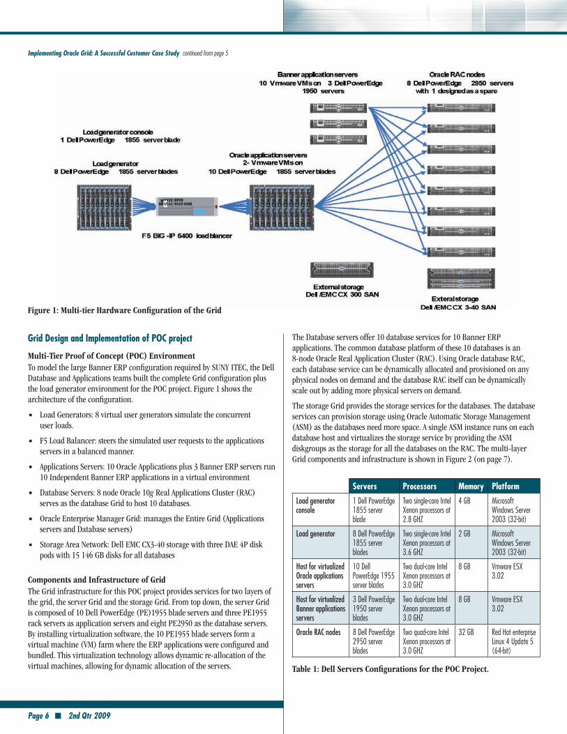
Multi-Tier Proof of Concept (POC) environmentTo model the large Banner ERP configuration required by SUNY ITEC, the Dell Database and Applications teams built the complete Grid configuration plus the load generator environment for the POC project. Figure 1 shows the architecture of the configuration.
Load Generators: 8 virtual user generators simulate the concurrent •user loads.
F5 Load Balancer: steers the simulated user requests to the applications •servers in a balanced manner.
Applications Servers: 10 Oracle Applications plus 3 Banner ERP servers run •10 Independent Banner ERP applications in a virtual environment
Database Servers: 8 node Oracle 10 • g Real Applications Cluster (RAC) serves as the database Grid to host 10 databases.
Oracle Enterprise Manager Grid: manages the Entire Grid (Applications •servers and Database servers)
Storage Area Network: Dell EMC CX3-40 storage with three DAE 4P disk •pods with 15 146 GB disks for all databases
Components and Infrastructure of GridThe Grid infrastructure for this POC project provides services for two layers of the grid, the server Grid and the storage Grid. From top down, the server Grid is composed of 10 Dell PowerEdge (PE)1955 blade servers and three PE1955 rack servers as application servers and eight PE2950 as the database servers. By installing virtualization software, the 10 PE1955 blade servers form a virtual machine (VM) farm where the ERP applications were configured and bundled. This virtualization technology allows dynamic re-allocation of the virtual machines, allowing for dynamic allocation of the servers.
The Database servers offer 10 database services for 10 Banner ERP applications. The common database platform of these 10 databases is an 8-node Oracle Real Application Cluster (RAC). Using Oracle database RAC, each database service can be dynamically allocated and provisioned on any physical nodes on demand and the database RAC itself can be dynamically scale out by adding more physical servers on demand.
The storage Grid provides the storage services for the databases. The database services can provision storage using Oracle Automatic Storage Management (ASM) as the databases need more space. A single ASM instance runs on each database host and virtualizes the storage service by providing the ASM diskgroups as the storage for all the databases on the RAC. The multi-layer Grid components and infrastructure is shown in Figure 2 (on page 7).
Implementing Oracle Grid: A Successful Customer Case Study continued from page 5
Figure 1: Multi-tier Hardware Configuration of the Grid
Servers Processors Memory Platform
Load generator console
1 Dell PowerEdge 1855 server blade
Two single-core Intel Xenon processors at 2.8 GHZ
4 GB Microsoft Windows Server 2003 (32-bit)
Load generator 8 Dell PowerEdge 1855 server blades
Two single-core Intel Xenon processors at 3.6 GHZ
2 GB Microsoft Windows Server 2003 (32-bit)
Host for virtualized Oracle applications servers
10 Dell PowerEdge 1955 server blades
Two dual-core Intel Xenon processors at 3.0 GHZ
8 GB Vmware ESX 3.02
Host for virtualized Banner applications servers
3 Dell PowerEdge 1950 server blades
Two dual-core Intel Xenon processors at 3.0 GHZ
8 GB Vmware ESX 3.02
Oracle RAC nodes 8 Dell PowerEdge 2950 server blades
Two quad-core Intel Xenon processors at 3.0 GHZ
32 GB Red Hat enterprise Linux 4 Update 5 (64-bit)
Table 1: Dell Servers Configurations for the POC Project.
2nd Qtr 2009 ■ Page 7
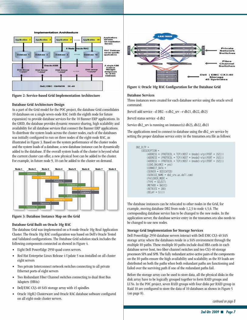
Database Grid architecture Design As a part of the Grid model for the POC project, the database Grid consolidates 10 databases on a single seven-node RAC (with the eighth node for future expansion) to provide database services for the 10 Banner ERP applications. In the GRID, the database provides dynamic resource sharing, high scalability and availability for all database services that connect the Banner ERP applications. To distribute the system loads across the cluster nodes, each of the databases was initially configured to run on three nodes of the eight-node RAC, as illustrated in Figure 3. Based on the system performance of the cluster nodes and the system loads of a database, a new database instance can be dynamically added to the database. If the overall system loads of the cluster is beyond what the current cluster can offer, a new physical host can be added to the cluster. For example, in future node 9, 10 can be added to the cluster on demand.
Figure 3: Database Instance Map on the Grid
Database Grid Built on Oracle 10g raC The database Grid was implemented on a 8-node Oracle 10g Real Application Cluster. The Oracle 10g RAC configuration was based on Dell’s Oracle Tested and Validated configurations. The Database Grid solution stack includes the following components connected as showed in Figure 4.
Eight Dell PowerEdge 2950 quad-cores servers. •Red Hat Enterprise Linux Release 4 Update 5 was installed on all cluster •eight servers
Two private Interconnect network switches connecting to all private •Ethernet ports of eight servers
Two Redundant Fiber Channel switches connecting to dual Host Bus •Adapters (HBAs)
Dell/EMC CX3-40 SAN storage array with 45 spindles •Oracle 10 • gR2 Clusterware and Oracle RAC database software configured on all eight-node cluster servers.
Figure 4: Oracle 10g raC Configuration for the Database Grid
Database Services Three instances were created for each database service using the oracle srvctl command:
$srvctl add service –d DB2 –s db2_srv –r db21, db22, db23
$srvctl status service -d db2
Service db2_srv is running on instance(s) db23, db22, db21
The applications need to connect to database using the db2_srv service by setting the proper database service entry in the tnsnames.ora file as follows:
DB2_OLTP = (DESCRIPTION = (ADDRESS = (PROTOCOL = TCP)(HOST = bnode1-vip)(PORT = 1521)) (ADDRESS = (PROTOCOL = TCP)(HOST = bnode2-vip)(PORT = 1521)) (ADDRESS = (PROTOCOL = TCP)(HOST = bnode3-vip)(PORT = 1521)) (LOAD_BALANCE = yes) (CONNECT_DATA = (SERVER = DEDICATED) (SERVICE_NAME = db2_srv.us.dell.com) (FAILOVER_MODE = (TYPE = SELECT) (METHOD = BASIC) (RETRIES = 180) (DELAY = 5))))
The database instances can be relocated to other nodes in the Grid, for example, moving database DB2 from node 1,2,3 to node 4,5,6. The corresponding database service has to be changed to the new nodes. In the application server, the database service entry in the tnsnames.ora also needs to be changed to use new nodes.
Storage Grid Implementation for Storage ServicesDell PowerEdge 2950 database servers interact with Dell EMC CX3-40 SAN storage array where the databases reside in a SAN environment through the multiple IO paths. These multiple IO paths include dual HBA cards in each database server host, two fiber channel switches and two CX3-40 storage processors SPA and SPB. The fully redundant active-active pairs of the components on the IO paths ensure the high availability and scalability as the IO loads are distributed on both the paths when both redundant paths are functioning and failed over the surviving path if one of the redundant paths fail.
Before the storage array can be used to store data, all the physical disks in the disk array have to be logically grouped together to form RAID groups and LUNs. In the POC project, seven RAID groups with four disks per RAID group in Raid 10 are configured to store the data of 10 databases as shown in Figure 5 (on page 8).
continued on page 8
Figure 2: Service-based Grid Implementation architecture
Page 8 ■ 2nd Qtr 2009
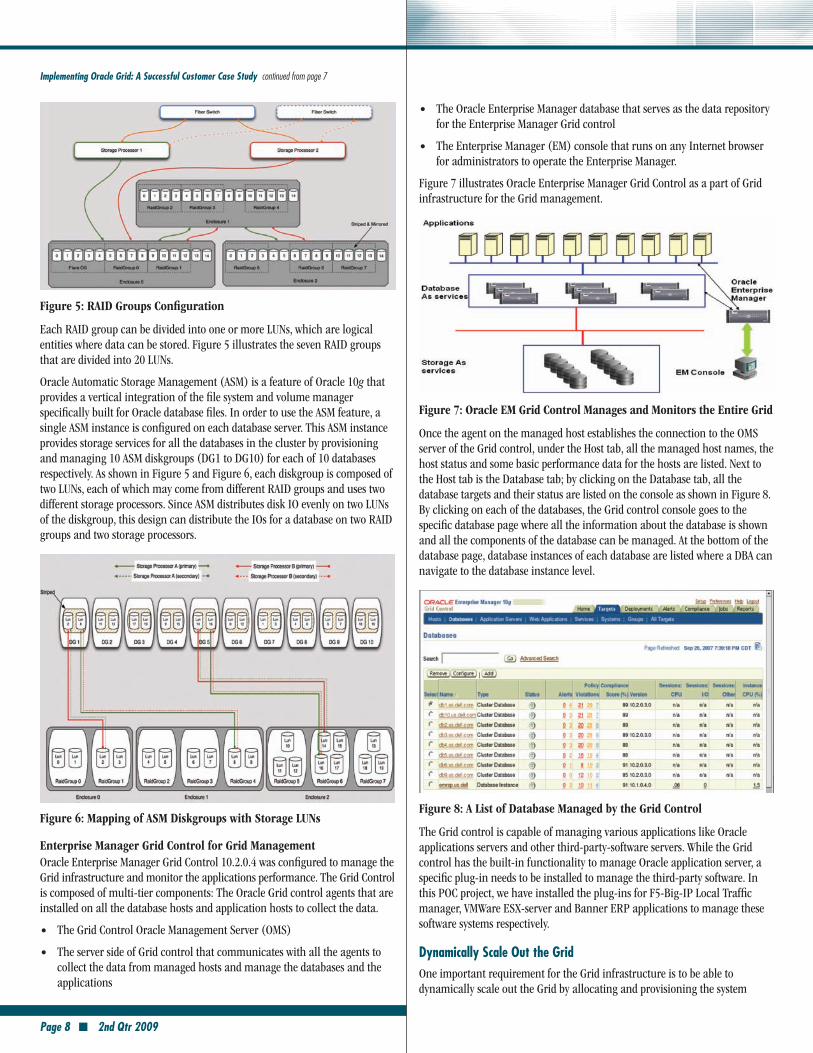
Figure 5: raID Groups Configuration
Each RAID group can be divided into one or more LUNs, which are logical entities where data can be stored. Figure 5 illustrates the seven RAID groups that are divided into 20 LUNs.
Oracle Automatic Storage Management (ASM) is a feature of Oracle 10g that provides a vertical integration of the file system and volume manager specifically built for Oracle database files. In order to use the ASM feature, a single ASM instance is configured on each database server. This ASM instance provides storage services for all the databases in the cluster by provisioning and managing 10 ASM diskgroups (DG1 to DG10) for each of 10 databases respectively. As shown in Figure 5 and Figure 6, each diskgroup is composed of two LUNs, each of which may come from different RAID groups and uses two different storage processors. Since ASM distributes disk IO evenly on two LUNs of the diskgroup, this design can distribute the IOs for a database on two RAID groups and two storage processors.
Figure 6: Mapping of aSM Diskgroups with Storage LUNs
enterprise Manager Grid Control for Grid ManagementOracle Enterprise Manager Grid Control 10.2.0.4 was configured to manage the Grid infrastructure and monitor the applications performance. The Grid Control is composed of multi-tier components: The Oracle Grid control agents that are installed on all the database hosts and application hosts to collect the data.
The Grid Control Oracle Management Server (OMS) •The server side of Grid control that communicates with all the agents to •collect the data from managed hosts and manage the databases and the applications
Implementing Oracle Grid: A Successful Customer Case Study continued from page 7
The Oracle Enterprise Manager database that serves as the data repository •for the Enterprise Manager Grid control
The Enterprise Manager (EM) console that runs on any Internet browser •for administrators to operate the Enterprise Manager.
Figure 7 illustrates Oracle Enterprise Manager Grid Control as a part of Grid infrastructure for the Grid management.
Figure 7: Oracle eM Grid Control Manages and Monitors the entire Grid
Once the agent on the managed host establishes the connection to the OMS server of the Grid control, under the Host tab, all the managed host names, the host status and some basic performance data for the hosts are listed. Next to the Host tab is the Database tab; by clicking on the Database tab, all the database targets and their status are listed on the console as shown in Figure 8. By clicking on each of the databases, the Grid control console goes to the specific database page where all the information about the database is shown and all the components of the database can be managed. At the bottom of the database page, database instances of each database are listed where a DBA can navigate to the database instance level.
Figure 8: a List of Database Managed by the Grid Control
The Grid control is capable of managing various applications like Oracle applications servers and other third-party-software servers. While the Grid control has the built-in functionality to manage Oracle application server, a specific plug-in needs to be installed to manage the third-party software. In this POC project, we have installed the plug-ins for F5-Big-IP Local Traffic manager, VMWare ESX-server and Banner ERP applications to manage these software systems respectively.
Dynamically Scale Out the GridOne important requirement for the Grid infrastructure is to be able to dynamically scale out the Grid by allocating and provisioning the system
2nd Qtr 2009 ■ Page 9
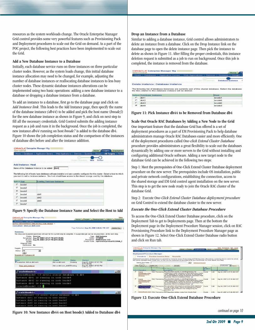
resources as the system workloads change. The Oracle Enterprise Manager Grid control provides some very powerful features such as Provisioning Pack and Deployment procedures to scale out the Grid on demand. As a part of the POC project, the following best practices have been implemented to scale out the Grid.
add a New Database Instance to a DatabaseInitially, each database service runs on three instances on three particular cluster nodes. However, as the system loads change, this initial database instance allocation may need to be changed, for example, adjusting the number of database instances or reallocating database instances to less busy cluster nodes. These dynamic database instances alterations can be implemented using two basic operations: adding a new database instance to a database or dropping a database instance from a database.
To add an instance to a database, first go to the database page and click on Add Instance link. This leads to the Add Instance page, then specify the name of the database instance (db44) to be added and pick the host name (bnode3) for the new database instance as shown in Figure 9, and click on next step to fill all the necessary credentials. Grid Control submits the adding instance request as a job and runs it in the background. Once the job is completed, the new instance db44 running on host bnode7 is added to the database db4. Figure 10 shows the job completion status and the comparison of the instances of database db4 before and after the instance addition.
Figure 9: Specify the Database Instance Name and Select the Host to add
Figure 10: New Instance db44 on Host bnode3 added to Database db4 continued on page 10
Drop an Instance from a DatabaseSimilar to adding a database instance, Grid control allows administrators to delete an instance from a database. Click on the Drop Instance link on the database page to open the delete instance page. Then pick the instance to delete as shown in Figure 11. After filling the proper credentials, this instance deletion request is submitted as a job to run on background. Once this job is completed, the instance is removed from the database.
Figure 11: Pick Instance db44 to be removed from Database db4
Scale Out Oracle raC Databases by adding a New Node to the GridOne important feature that the database Grid has offered is a set of deployment procedures as a part of EM Provisioning Pack to help database administrators manage Oracle RAC Databases easier and more efficiently. One of the deployment procedures called One-click Extend Cluster Database procedure provides administrators a great flexibility to scale out the databases dynamically by adding one or more servers to the Grid without installing and configuring additional Oracle software. Adding a new target node to the database Grid can be achieved in the following two steps:
Step 1: Meet the prerequisites of One-Click Extend Cluster Database deployment procedure on the new server. The prerequisites include OS installation, public and private network configurations, establishing the connection, access to the shared storage and EM Grid control agent installation on the new server. This step is to get the new node ready to join the Oracle RAC cluster of the database Grid.
Step 2: Execute One-Click Extend Cluster Database deployment procedure on Grid Control to extend the database cluster to the new server.
Execute the One-Click Extend Cluster Database Procedure
To access the One-Click Extend Cluster Database procedure, click on the Deployment Tab to get to Deployments page. Then at the bottom the Deployment page in the Deployment Procedure Manager session, click on RAC Provisioning Procedure link to the Deployment Procedure Manager page as shown in Figure 12. Select One-Click Extend Cluster Database radio button and click on Run tab.
Figure 12: execute One-Click extend Database Procedure
Page 10 ■ 2nd Qtr 2009
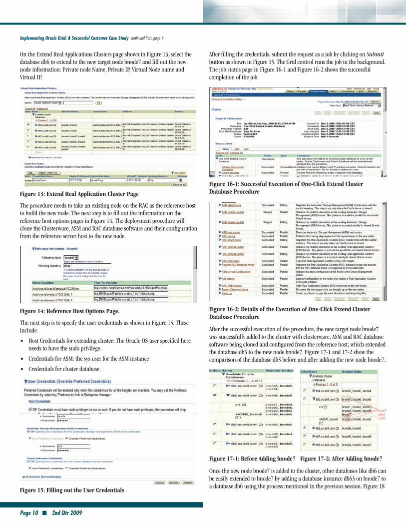
After filling the credentials, submit the request as a job by clicking on Submit button as shown in Figure 15. The Grid control runs the job in the background. The job status page in Figure 16-1 and Figure 16-2 shows the successful completion of the job.
Figure 16-1: Successful execution of One-Click extend Cluster Database Procedure
Figure 16-2: Details of the execution of One-Click extend Cluster Database Procedure
After the successful execution of the procedure, the new target node bnode7 was successfully added to the cluster with clusterware, ASM and RAC database software being cloned and configured from the reference host; which extended the database db5 to the new node bnode7. Figure 17-1 and 17-2 show the comparison of the database db5 before and after adding the new node bnode7.
Figure 17-1: Before adding bnode7 Figure 17-2: after adding bnode7
Once the new node bnode7 is added to the cluster, other databases like db6 can be easily extended to bnode7 by adding a database instance db63 on bnode7 to a database db6 using the process mentioned in the previous session. Figure 18
Implementing Oracle Grid: A Successful Customer Case Study continued from page 9
On the Extend Real Applications Clusters page shown in Figure 13, select the database db6 to extend to the new target node bnode7 and fill out the new node information: Private node Name, Private IP, Virtual Node name and Virtual IP.
Figure 13: extend real application Cluster Page
The procedure needs to take an existing node on the RAC as the reference host to build the new node. The next step is to fill out the information on the reference host options pages in Figure 14. The deployment procedure will clone the Clusterware, ASM and RAC database software and their configuration from the reference server host to the new node.
Figure 14: reference Host Options Page.
The next step is to specify the user credentials as shown in Figure 15. These include:
Host Credentials for extending cluster: The Oracle OS user specified here •needs to have the sudo privilege.
Credentials for ASM: the sys user for the ASM instance •Credentials for cluster database. •
Figure 15: Filling out the User Credentials
2nd Qtr 2009 ■ Page 11
shows the database db5 and db6 instances, and the nodeapps and all the pmon processes for ASM instance, the third instance of db5 (db53) and the third instance of db6(db63) running on the new node bnode7.
Figure 18: New Node bnode7 added into the Cluster Database db5 and db6
Application Test MethodologyAs described in the beginning of this article, the goal of this POC project was to demonstrate that Grid running Banner ERP applications can scale to meet the required application loads. To model the application loads, the team decided to focus on five of the most common student user actions for the POC testing: student registration, viewing class lists and grades, and adding or dropping classes. LoadRunner workload generators were programmed with input keystrokes and Web clicks for these students’ actions to simulate a specific number of users performing the various functions at any given time. All the databases are categorized into two different database sizes: large DB and small DB by number of simultaneous users at any given time. Table 2 shows the number of simultaneous users per function for both sizes of the databases involved in the testing.
Function # Virtual Users per Large DB
# Virtual Users per Small DB
Performing a traditional course registration 320 80
Performing a shopping-card course registration 320 80
View Class List 200 50
Add or Drop Classes 160 40
View Grades 800 200
Total 1,800 450
Table 2: Simultaneous Simulated User per Student Function
The test teams built upon the previous Banner ERP POC project with Texas Tech University: The larger DB was representative of a school with 28,000 students and the smaller DB representative of a smaller campus with only 7,000 students. To vary the system load testing for multiple Banner ERP applications under various degrees, the test teams established three load testing points:
1+1 : One large + one small, total 35,000 students •3+3 : Three large + three small, total 105,000 students •5+5 : Five large + five small, total 175, 000 students •
Table 3 defines the simultaneous users for various universities.
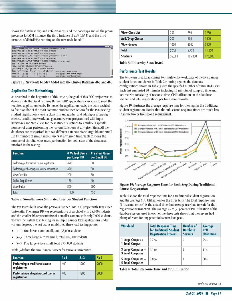
Function 1+1 3+3 5+5
Performing a traditional course registration
400 1200 2000
Performing a shopping-card course registration
400 1200 2000
View Class List 250 750 1250
Add/Drop Classes 200 600 1000
View Grades 1000 3000 5000
Total 2,250 6,750 11,250
Students 35,000 105,000 175,000
Table 3: University Sizes Tested
Performance Test ResultsThe test team used LoadRunner to simulate the workloads of the five Banner student functions shown in Table 2 running against the database configurations shown in Table 3 with the specified number of simulated users. Each test run lasted 90 minutes including 10 minutes of ramp-up time and key metrics consisting of response time, CPU utilization on the database servers, and total registrations per time were recorded.
Figure 19 illustrates the average response time for the steps in the traditional student registration. Notice that the sub-second response times are much less than the two or five second requirement.
Figure 19: average response Time for each Step During Traditional Course registration
Table 4 shows the total response time for a traditional student registration and the average CPU Utilization for the three tests. The total response time (1.1 second or less) is the actual time that average user had to wait for the registration transaction. The average 25 to 30 percent CPU Utilization of the database servers used in each of the three tests shows that the servers had plenty of room for any potential system load peak.
Workload Total Response Time for Traditional Student Registration Process
Number of Database Servers
Average CPU Utilization
1 Large Campus + 1 Small Campus
0.7 sec 3 25%
3 Large Campuses + 3 Small Campuses
1.1 sec 5 31%
5 Large Campuses + 5 Small Campuses
0.8 sec 6 30%
Table 4: Total response Time and CPU Utilization
continued on page 12
Page 12 ■ 2nd Qtr 2009
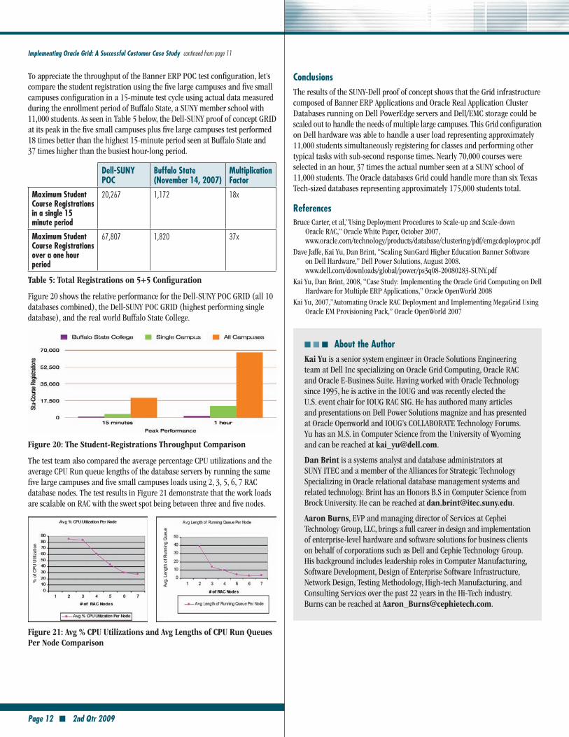
To appreciate the throughput of the Banner ERP POC test configuration, let’s compare the student registration using the five large campuses and five small campuses configuration in a 15-minute test cycle using actual data measured during the enrollment period of Buffalo State, a SUNY member school with 11,000 students. As seen in Table 5 below, the Dell-SUNY proof of concept GRID at its peak in the five small campuses plus five large campuses test performed 18 times better than the highest 15-minute period seen at Buffalo State and 37 times higher than the busiest hour-long period.
Dell-SUNY POC
Buffalo State (November 14, 2007)
Multiplication Factor
Maximum Student Course Registrations in a single 15 minute period
20,267 1,172 18x
Maximum Student Course Registrations over a one hour period
67,807 1,820 37x
Table 5: Total registrations on 5+5 Configuration
Figure 20 shows the relative performance for the Dell-SUNY POC GRID (all 10 databases combined), the Dell-SUNY POC GRID (highest performing single database), and the real world Buffalo State College.
Figure 20: The Student-registrations Throughput Comparison
The test team also compared the average percentage CPU utilizations and the average CPU Run queue lengths of the database servers by running the same five large campuses and five small campuses loads using 2, 3, 5, 6, 7 RAC database nodes. The test results in Figure 21 demonstrate that the work loads are scalable on RAC with the sweet spot being between three and five nodes.
% o
f CP
U U
tiliz
atio
n
Avg.
Len
gth
of R
unni
ng Q
ueue
Figure 21: avg % CPU Utilizations and avg Lengths of CPU run Queues Per Node Comparison
Implementing Oracle Grid: A Successful Customer Case Study continued from page 11
ConclusionsThe results of the SUNY-Dell proof of concept shows that the Grid infrastructure composed of Banner ERP Applications and Oracle Real Application Cluster Databases running on Dell PowerEdge servers and Dell/EMC storage could be scaled out to handle the needs of multiple large campuses. This Grid configuration on Dell hardware was able to handle a user load representing approximately 11,000 students simultaneously registering for classes and performing other typical tasks with sub-second response times. Nearly 70,000 courses were selected in an hour, 37 times the actual number seen at a SUNY school of 11,000 students. The Oracle databases Grid could handle more than six Texas Tech-sized databases representing approximately 175,000 students total.
ReferencesBruce Carter, et al,”Using Deployment Procedures to Scale-up and Scale-down
Oracle RAC,” Oracle White Paper, October 2007, www.oracle.com/technology/products/database/clustering/pdf/emgcdeployproc.pdf
Dave Jaffe, Kai Yu, Dan Brint, “Scaling SunGard Higher Education Banner Software on Dell Hardware,” Dell Power Solutions, August 2008. www.dell.com/downloads/global/power/ps3q08-20080283-SUNY.pdf
Kai Yu, Dan Brint, 2008, “Case Study: Implementing the Oracle Grid Computing on Dell Hardware for Multiple ERP Applications,” Oracle OpenWorld 2008
Kai Yu, 2007,”Automating Oracle RAC Deployment and Implementing MegaGrid Using Oracle EM Provisioning Pack,” Oracle OpenWorld 2007
■ ■ ■ About the Authorkai Yu is a senior system engineer in Oracle Solutions Engineering team at Dell Inc specializing on Oracle Grid Computing, Oracle RAC and Oracle E-Business Suite. Having worked with Oracle Technology since 1995, he is active in the IOUG and was recently elected the U.S. event chair for IOUG RAC SIG. He has authored many articles and presentations on Dell Power Solutions magnize and has presented at Oracle Openworld and IOUG’s COLLABORATE Technology Forums. Yu has an M.S. in Computer Science from the University of Wyoming and can be reached at [email protected].
Dan Brint is a systems analyst and database administrators at SUNY ITEC and a member of the Alliances for Strategic Technology Specializing in Oracle relational database management systems and related technology. Brint has an Honors B.S in Computer Science from Brock University. He can be reached at [email protected].
aaron Burns, EVP and managing director of Services at Cephei Technology Group, LLC, brings a full career in design and implementation of enterprise-level hardware and software solutions for business clients on behalf of corporations such as Dell and Cephie Technology Group. His background includes leadership roles in Computer Manufacturing, Software Development, Design of Enterprise Software Infrastructure, Network Design, Testing Methodology, High-tech Manufacturing, and Consulting Services over the past 22 years in the Hi-Tech industry.Burns can be reached at [email protected].