Embed Size (px)
Citation preview
Important Information, Maintenance, andTroubleshooting
Section 1C - Maintenance
Table of Contents
Engine and Tune‑Up Specifications.................................. 1C-3Notes on Engine Specifications..................................1C-34.3 MPI ECT............................................................... 1C-3
Fluid Specifications............................................................1C-3Engine........................................................................ 1C-3Power‑Assisted Steering and Power Trim Fluids....... 1C-4
Maintenance Intervals........................................................1C-4Maintenance Schedules.................................................... 1C-4
Routine Maintenance..................................................1C-4Scheduled Maintenance............................................. 1C-5
Engine Oil.......................................................................... 1C-6Checking and Filling the Engine Oil............................1C-6Changing the Engine Oil and Filter.............................1C-7
Power Trim Fluid................................................................1C-9Checking.....................................................................1C-9Filling........................................................................ 1C-10Changing.................................................................. 1C-10
Flame Arrestor................................................................. 1C-11Exploded View..........................................................1C-11
IAC Muffler.......................................................................1C-11Removal................................................................... 1C-11Cleaning and Inspection........................................... 1C-12Installation................................................................ 1C-12
Serpentine Drive Belt.......................................................1C-13Sterndrive Models.....................................................1C-13
Closed‑Cooling System................................................... 1C-15Checking Coolant Level............................................1C-15Cleaning and Inspection........................................... 1C-16Changing Coolant.....................................................1C-16
Power‑Assisted Steering Fluid.........................................1C-16Changing.................................................................. 1C-18
Compact Hydraulic Steering............................................ 1C-18System Check.......................................................... 1C-18
Sterndrive Gear Lube...................................................... 1C-18Checking...................................................................1C-18Filling........................................................................ 1C-19
Visual Inspections............................................................1C-19Battery...................................................................... 1C-19Instruments...............................................................1C-19Remote Control........................................................ 1C-19Electrical System...................................................... 1C-19Exhaust System........................................................1C-20Seawater Pump........................................................ 1C-20
Steering System Lubrication............................................1C-20Corrosion Prevention ...................................................... 1C-21
Maintaining Ground Circuit Continuity...................... 1C-21MerCathode..............................................................1C-24Power Package Exterior Surfaces............................1C-24
Seawater System.............................................................1C-24Cleaning the Seawater Strainer, If Equipped........... 1C-24Checking the Seawater Pickups...............................1C-25
Draining the Seawater System........................................ 1C-25Drain System Identification.......................................1C-26Air Actuated Single‑Point Drain System................... 1C-27Manual Single‑Point Drain System...........................1C-30Manual Single‑Point Drain System with Plug........... 1C-31Three‑Point Manual Drain System........................... 1C-32
Flushing the Power Package (Alpha).............................. 1C-34Flushing Attachments............................................... 1C-34Sterndrive Water Pickups......................................... 1C-34
Flushing the Power Package (Bravo).............................. 1C-35Flushing the Power Package....................................1C-35SeaCore Power Package Flushing Procedure......... 1C-38
Cold Weather or Extended Storage.................................1C-41Preparing the Power Package for Storage............... 1C-42
Power Package Recommissioning.................................. 1C-43
Maintenance
90-8M0041669 JANUARY 2014 Page 1C-1
1C
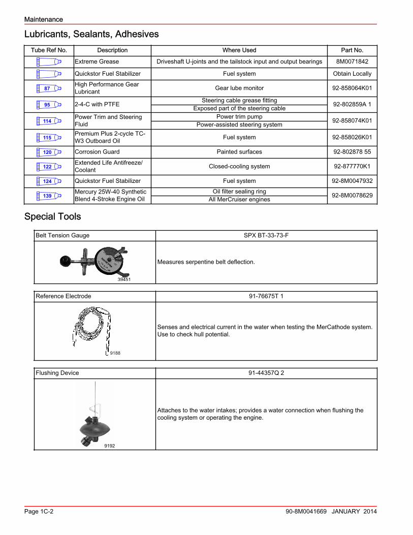
Lubricants, Sealants, AdhesivesTube Ref No. Description Where Used Part No.
Extreme Grease Driveshaft U-joints and the tailstock input and output bearings 8M0071842
Quickstor Fuel Stabilizer Fuel system Obtain Locally
87High Performance GearLubricant Gear lube monitor 92-858064K01
95 2-4-C with PTFE Steering cable grease fittingExposed part of the steering cable 92-802859A 1
114Power Trim and SteeringFluid
Power trim pumpPower-assisted steering system 92-858074K01
115Premium Plus 2-cycle TC-W3 Outboard Oil Fuel system 92-858026K01
120 Corrosion Guard Painted surfaces 92-802878 55
122Extended Life Antifreeze/Coolant Closed-cooling system 92-877770K1
124 Quickstor Fuel Stabilizer Fuel system 92-8M0047932
139Mercury 25W-40 SyntheticBlend 4-Stroke Engine Oil
Oil filter sealing ringAll MerCruiser engines 92-8M0078629
Special Tools
Belt Tension Gauge SPX BT‑33‑73‑F
39451
Measures serpentine belt deflection.
Reference Electrode 91‑76675T 1
9188
Senses and electrical current in the water when testing the MerCathode system.Use to check hull potential.
Flushing Device 91‑44357Q 2
9192
Attaches to the water intakes; provides a water connection when flushing thecooling system or operating the engine.
Maintenance
Page 1C-2 90-8M0041669 JANUARY 2014
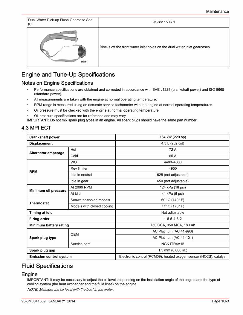
Dual Water Pick‑up Flush Gearcase SealKit 91‑881150K 1
9194
Blocks off the front water inlet holes on the dual water inlet gearcases.
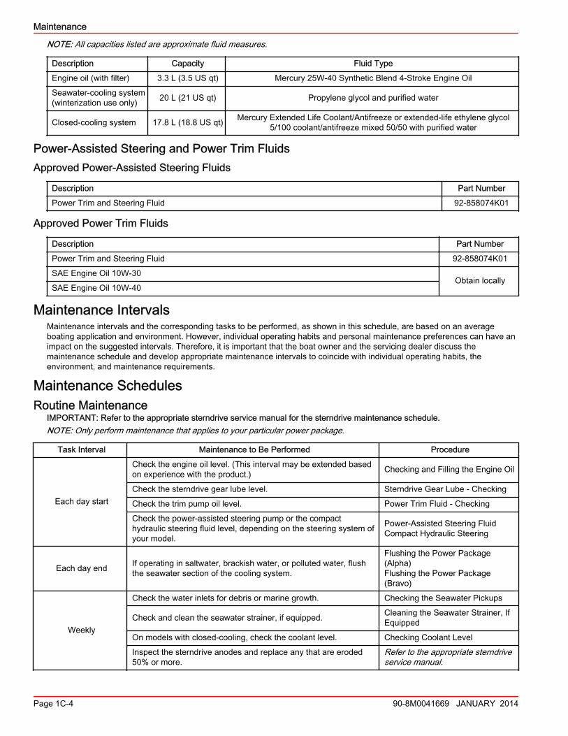
Engine and Tune‑Up SpecificationsNotes on Engine Specifications
• Performance specifications are obtained and corrected in accordance with SAE J1228 (crankshaft power) and ISO 8665(standard power).
• All measurements are taken with the engine at normal operating temperature.• RPM range is measured using an accurate service tachometer with the engine at normal operating temperatures.• Oil pressure must be checked with the engine at normal operating temperature.• Oil pressure specifications are for reference and may vary.IMPORTANT: Do not mix spark plug types in an engine. All spark plugs should have the same part number.
4.3 MPI ECT
Crankshaft power 164 kW (220 hp)
Displacement 4.3 L (262 cid)
Alternator amperageHot 72 A
Cold 65 A
RPM
WOT 4400–4800
Rev limiter 4950
Idle in neutral 625 (not adjustable)
Idle in gear 650 (not adjustable)
Minimum oil pressureAt 2000 RPM 124 kPa (18 psi)
At idle 41 kPa (6 psi)
ThermostatSeawater‑cooled models 60° C (140° F)
Models with closed cooling 77° C (170° F)
Timing at idle Not adjustable
Firing order 1‑6‑5‑4‑3‑2
Minimum battery rating 750 CCA, 950 MCA, 180 Ah
Spark plug typeOEM
AC Platinum (AC 41‑993)
AC Platinum (AC 41‑101)
Service part NGK ITR4A15
Spark plug gap 1.5 mm (0.060 in.)
Emission control system Electronic control (PCM09), heated oxygen sensor (HO2S), catalyst
Fluid SpecificationsEngine
IMPORTANT: It may be necessary to adjust the oil levels depending on the installation angle of the engine and the type ofcooling system (the heat exchanger and the fluid lines) on the engine.NOTE: Measure the oil level with the boat in the water.
Maintenance
90-8M0041669 JANUARY 2014 Page 1C-3
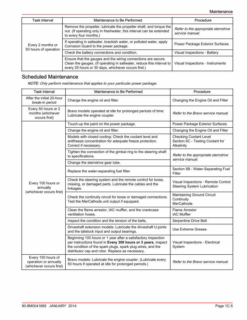
NOTE: All capacities listed are approximate fluid measures.
Description Capacity Fluid Type
Engine oil (with filter) 3.3 L (3.5 US qt) Mercury 25W‑40 Synthetic Blend 4‑Stroke Engine Oil
Seawater‑cooling system(winterization use only) 20 L (21 US qt) Propylene glycol and purified water
Closed‑cooling system 17.8 L (18.8 US qt) Mercury Extended Life Coolant/Antifreeze or extended‑life ethylene glycol5/100 coolant/antifreeze mixed 50/50 with purified water
Power‑Assisted Steering and Power Trim FluidsApproved Power-Assisted Steering Fluids
Description Part Number
Power Trim and Steering Fluid 92‑858074K01
Approved Power Trim Fluids
Description Part Number
Power Trim and Steering Fluid 92‑858074K01
SAE Engine Oil 10W‑30Obtain locally
SAE Engine Oil 10W‑40
Maintenance IntervalsMaintenance intervals and the corresponding tasks to be performed, as shown in this schedule, are based on an averageboating application and environment. However, individual operating habits and personal maintenance preferences can have animpact on the suggested intervals. Therefore, it is important that the boat owner and the servicing dealer discuss themaintenance schedule and develop appropriate maintenance intervals to coincide with individual operating habits, theenvironment, and maintenance requirements.
Maintenance SchedulesRoutine Maintenance
IMPORTANT: Refer to the appropriate sterndrive service manual for the sterndrive maintenance schedule.NOTE: Only perform maintenance that applies to your particular power package.
Task Interval Maintenance to Be Performed Procedure
Each day start
Check the engine oil level. (This interval may be extended basedon experience with the product.) Checking and Filling the Engine Oil
Check the sterndrive gear lube level. Sterndrive Gear Lube ‑ Checking
Check the trim pump oil level. Power Trim Fluid ‑ Checking
Check the power‑assisted steering pump or the compacthydraulic steering fluid level, depending on the steering system ofyour model.
Power‑Assisted Steering FluidCompact Hydraulic Steering
Each day end If operating in saltwater, brackish water, or polluted water, flushthe seawater section of the cooling system.
Flushing the Power Package(Alpha)Flushing the Power Package(Bravo)
Weekly
Check the water inlets for debris or marine growth. Checking the Seawater Pickups
Check and clean the seawater strainer, if equipped. Cleaning the Seawater Strainer, IfEquipped
On models with closed‑cooling, check the coolant level. Checking Coolant Level
Inspect the sterndrive anodes and replace any that are eroded50% or more.
Refer to the appropriate sterndriveservice manual.
Maintenance
Page 1C-4 90-8M0041669 JANUARY 2014
Task Interval Maintenance to Be Performed Procedure
Every 2 months or50 hours of operation
Remove the propeller, lubricate the propeller shaft, and torque thenut. (If operating only in freshwater, this interval can be extendedto every four months.)
Refer to the appropriate sterndriveservice manual.
If operating in saltwater, brackish water, or polluted water, applyCorrosion Guard to the power package. Power Package Exterior Surfaces
Check the battery connections and condition. Visual Inspections ‑ Battery
Ensure that the gauges and the wiring connections are secure.Clean the gauges. (If operating in saltwater, reduce this interval toevery 25 hours or 30 days, whichever occurs first.)
Visual Inspections ‑ Instruments
Scheduled MaintenanceNOTE: Only perform maintenance that applies to your particular power package.
Task Interval Maintenance to Be Performed Procedure
After the initial 20‑hourbreak‑in period Change the engine oil and filter. Changing the Engine Oil and Filter
Every 50 hours or 2months (whichever
occurs first)
Bravo models operated at idle for prolonged periods of time:Lubricate the engine coupler. Refer to the Bravo service manual.
Every 100 hours orannually
(whichever occurs first)
Touch‑up the paint on the power package. Power Package Exterior Surfaces
Change the engine oil and filter. Changing the Engine Oil and Filter
Models with closed cooling: Check the coolant level andantifreeze concentration for adequate freeze protection.Correct if necessary.
Checking Coolant LevelSection 6C ‑ Testing Coolant forAlkalinity
Tighten the connection of the gimbal ring to the steering shaftto specifications. Refer to the appropriate sterndrive
service manual.Change the sterndrive gear lube.
Replace the water‑separating fuel filter. Section 5B ‑ Water‑Separating FuelFilter
Check the steering system and the remote control for loose,missing, or damaged parts. Lubricate the cables and thelinkages.
Visual Inspections ‑ Remote ControlSteering System Lubrication
Check the continuity circuit for loose or damaged connections.Test the MerCathode unit output if equipped.
Maintaining Ground CircuitContinuityMerCathode
Clean the flame arrestor, IAC muffler, and the crankcaseventilation hoses.
Flame ArrestorIAC Muffler
Inspect the condition and the tension of the belts. Serpentine Drive Belt
Driveshaft extension models: Lubricate the driveshaft U‑jointsand the tailstock input and output bearings. Use Extreme Grease.
Beginning 100 hours or 1 year after a satisfactory inspectionper instructions found in Every 300 hours or 3 years, inspectthe condition of the spark plugs, spark plug wires, and thedistributor cap and rotor. Replace as necessary.
Visual Inspections ‑ ElectricalSystem
Every 150 hours ofoperation or annually
(whichever occurs first)
Bravo models: Lubricate the engine coupler. (Lubricate every50 hours if operated at idle for prolonged periods.) Refer to the Bravo service manual.
Maintenance
90-8M0041669 JANUARY 2014 Page 1C-5
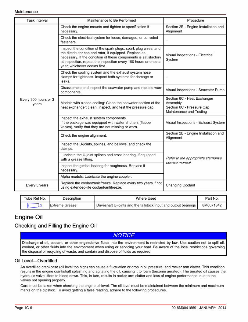
Task Interval Maintenance to Be Performed Procedure
Every 300 hours or 3years
Check the engine mounts and tighten to specification ifnecessary.
Section 2B ‑ Engine Installation andAlignment
Check the electrical system for loose, damaged, or corrodedfasteners. –
Inspect the condition of the spark plugs, spark plug wires, andthe distributor cap and rotor, if equipped. Replace asnecessary. If the condition of these components is satisfactoryat inspection, repeat the inspection every 100 hours or once ayear, whichever occurs first.
Visual Inspections ‑ ElectricalSystem
Check the cooling system and the exhaust system hoseclamps for tightness. Inspect both systems for damage orleaks.
–
Disassemble and inspect the seawater pump and replace worncomponents. Visual Inspections ‑ Seawater Pump
Models with closed cooling: Clean the seawater section of theheat exchanger; clean, inspect, and test the pressure cap.
Section 6C ‑ Heat ExchangerAssemblySection 6C ‑ Pressure CapMaintenance and Testing
Inspect the exhaust system components.If the package was equipped with water shutters (flappervalves), verify that they are not missing or worn.
Visual Inspections ‑ Exhaust System
Check the engine alignment. Section 2B ‑ Engine Installation andAlignment
Inspect the U‑joints, splines, and bellows, and check theclamps.
Refer to the appropriate sterndriveservice manual.
Lubricate the U‑joint splines and cross bearing, if equippedwith a grease fitting.
Inspect the gimbal bearing for roughness. Replace ifnecessary.
Alpha models: Lubricate the engine coupler.
Every 5 years Replace the coolant/anitifreeze. Replace every two years if notusing extended‑life coolant/antifreeze. Changing Coolant
Tube Ref No. Description Where Used Part No.
Extreme Grease Driveshaft U-joints and the tailstock input and output bearings 8M0071842
Engine OilChecking and Filling the Engine Oil
NOTICEDischarge of oil, coolant, or other engine/drive fluids into the environment is restricted by law. Use caution not to spill oil,coolant, or other fluids into the environment when using or servicing your boat. Be aware of the local restrictions governingthe disposal or recycling of waste, and contain and dispose of fluids as required.
Oil Level—OverfilledAn overfilled crankcase (oil level too high) can cause a fluctuation or drop in oil pressure, and rocker arm clatter. This conditionresults in the engine crankshaft splashing and agitating the oil, causing it to foam (become aerated). The aerated oil causes thehydraulic valve lifters to bleed down. This, in turn, results in rocker arm clatter and loss of engine performance, due to thevalves not opening properly.Care must be taken when checking the engine oil level. The oil level must be maintained between the minimum and maximummarks on the dipstick. To avoid getting a false reading, adhere to the following procedures.
Maintenance
Page 1C-6 90-8M0041669 JANUARY 2014
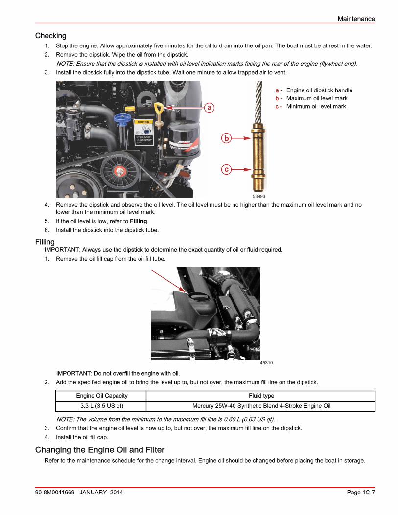
Checking1. Stop the engine. Allow approximately five minutes for the oil to drain into the oil pan. The boat must be at rest in the water.2. Remove the dipstick. Wipe the oil from the dipstick.
NOTE: Ensure that the dipstick is installed with oil level indication marks facing the rear of the engine (flywheel end).3. Install the dipstick fully into the dipstick tube. Wait one minute to allow trapped air to vent.
a - Engine oil dipstick handleb - Maximum oil level markc - Minimum oil level mark
4. Remove the dipstick and observe the oil level. The oil level must be no higher than the maximum oil level mark and nolower than the minimum oil level mark.
5. If the oil level is low, refer to Filling.6. Install the dipstick into the dipstick tube.
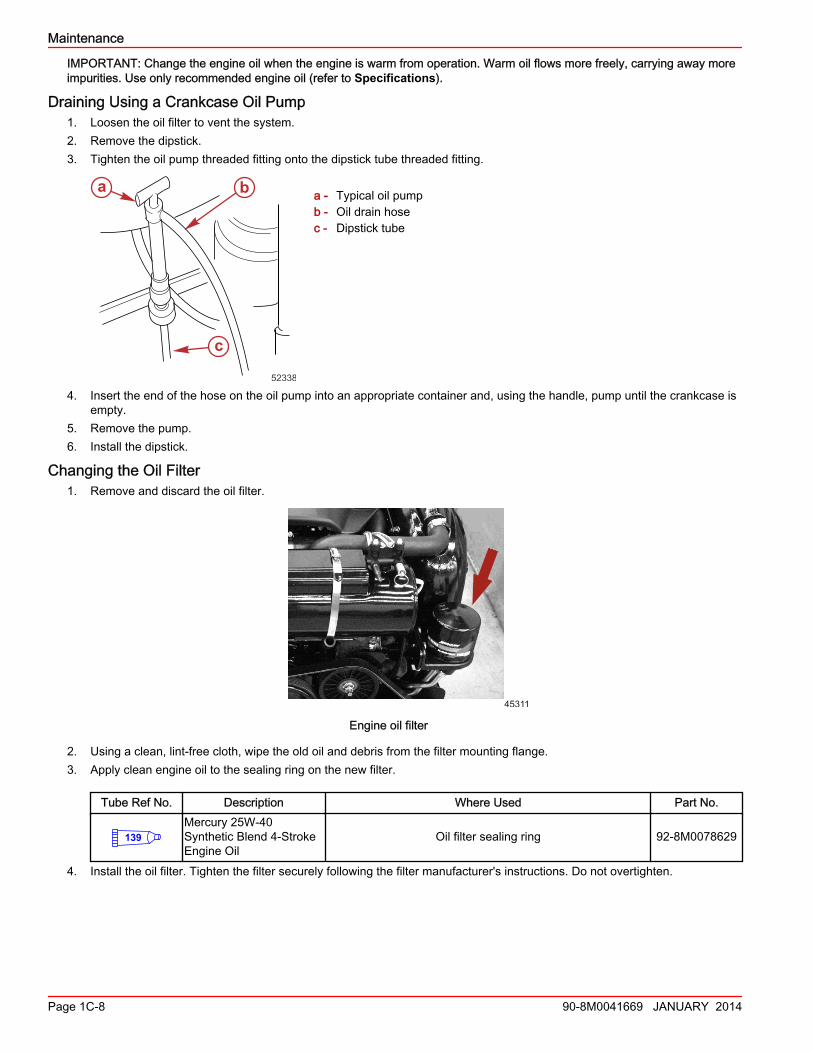
FillingIMPORTANT: Always use the dipstick to determine the exact quantity of oil or fluid required.1. Remove the oil fill cap from the oil fill tube.
45310
IMPORTANT: Do not overfill the engine with oil.2. Add the specified engine oil to bring the level up to, but not over, the maximum fill line on the dipstick.
Engine Oil Capacity Fluid type
3.3 L (3.5 US qt) Mercury 25W‑40 Synthetic Blend 4‑Stroke Engine Oil
NOTE: The volume from the minimum to the maximum fill line is 0.60 L (0.63 US qt).3. Confirm that the engine oil level is now up to, but not over, the maximum fill line on the dipstick.4. Install the oil fill cap.
Changing the Engine Oil and FilterRefer to the maintenance schedule for the change interval. Engine oil should be changed before placing the boat in storage.
a
b
c
53993
Maintenance
90-8M0041669 JANUARY 2014 Page 1C-7
IMPORTANT: Change the engine oil when the engine is warm from operation. Warm oil flows more freely, carrying away moreimpurities. Use only recommended engine oil (refer to Specifications).
Draining Using a Crankcase Oil Pump1. Loosen the oil filter to vent the system.2. Remove the dipstick.3. Tighten the oil pump threaded fitting onto the dipstick tube threaded fitting.
a - Typical oil pumpb - Oil drain hosec - Dipstick tube
4. Insert the end of the hose on the oil pump into an appropriate container and, using the handle, pump until the crankcase isempty.
5. Remove the pump.6. Install the dipstick.
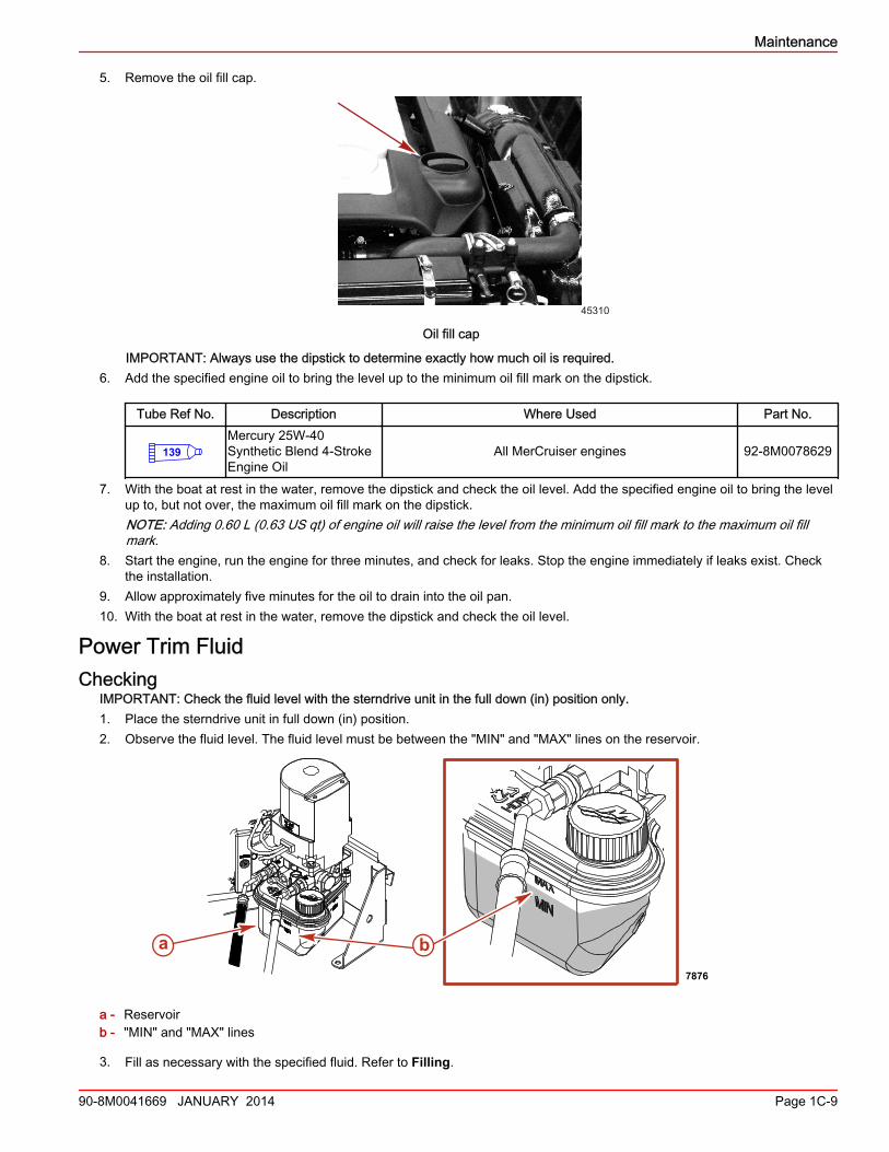
Changing the Oil Filter1. Remove and discard the oil filter.
45311
Engine oil filter
2. Using a clean, lint‑free cloth, wipe the old oil and debris from the filter mounting flange.3. Apply clean engine oil to the sealing ring on the new filter.
Tube Ref No. Description Where Used Part No.
139Mercury 25W-40Synthetic Blend 4-StrokeEngine Oil
Oil filter sealing ring 92-8M0078629
4. Install the oil filter. Tighten the filter securely following the filter manufacturer's instructions. Do not overtighten.
a b
c
52338
Maintenance
Page 1C-8 90-8M0041669 JANUARY 2014
5. Remove the oil fill cap.
45310
Oil fill cap
IMPORTANT: Always use the dipstick to determine exactly how much oil is required.6. Add the specified engine oil to bring the level up to the minimum oil fill mark on the dipstick.
Tube Ref No. Description Where Used Part No.
139Mercury 25W-40Synthetic Blend 4-StrokeEngine Oil
All MerCruiser engines 92-8M0078629
7. With the boat at rest in the water, remove the dipstick and check the oil level. Add the specified engine oil to bring the levelup to, but not over, the maximum oil fill mark on the dipstick.NOTE: Adding 0.60 L (0.63 US qt) of engine oil will raise the level from the minimum oil fill mark to the maximum oil fillmark.
8. Start the engine, run the engine for three minutes, and check for leaks. Stop the engine immediately if leaks exist. Checkthe installation.
9. Allow approximately five minutes for the oil to drain into the oil pan.10. With the boat at rest in the water, remove the dipstick and check the oil level.
Power Trim FluidChecking
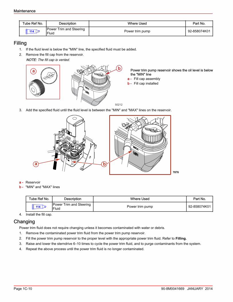
IMPORTANT: Check the fluid level with the sterndrive unit in the full down (in) position only.1. Place the sterndrive unit in full down (in) position.2. Observe the fluid level. The fluid level must be between the "MIN" and "MAX" lines on the reservoir.
a - Reservoirb - "MIN" and "MAX" lines
3. Fill as necessary with the specified fluid. Refer to Filling.
a b7876
Maintenance
90-8M0041669 JANUARY 2014 Page 1C-9
Tube Ref No. Description Where Used Part No.
114Power Trim and SteeringFluid Power trim pump 92-858074K01
Filling1. If the fluid level is below the "MIN" line, the specified fluid must be added.2. Remove the fill cap from the reservoir.
NOTE: The fill cap is vented.
Power trim pump reservoir shows the oil level is belowthe "MIN" line
a - Fill cap assemblyb - Fill cap installed
3. Add the specified fluid until the fluid level is between the "MIN" and "MAX" lines on the reservoir.
a - Reservoirb - "MIN" and "MAX" lines
Tube Ref No. Description Where Used Part No.
114Power Trim and SteeringFluid Power trim pump 92-858074K01
4. Install the fill cap.
ChangingPower trim fluid does not require changing unless it becomes contaminated with water or debris.1. Remove the contaminated power trim fluid from the power trim pump reservoir.2. Fill the power trim pump reservoir to the proper level with the appropriate power trim fluid. Refer to Filling.3. Raise and lower the sterndrive 6–10 times to cycle the power trim fluid, and to purge contaminants from the system.4. Repeat the above process until the power trim fluid is no longer contaminated.
ba
50212
a b7876
Maintenance
Page 1C-10 90-8M0041669 JANUARY 2014
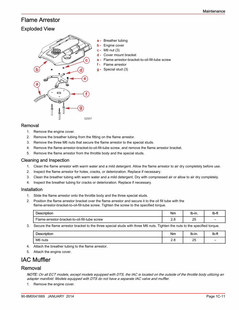
Flame ArrestorExploded View
a - Breather tubingb - Engine coverc - M6 nut (3)d - Cover mount brackete - Flame‑arrestor‑bracket‑to‑oil‑fill‑tube screwf - Flame arrestorg - Special stud (3)
Removal1. Remove the engine cover.2. Remove the breather tubing from the fitting on the flame arrestor.3. Remove the three M6 nuts that secure the flame arrestor to the special studs.4. Remove the flame‑arrestor‑bracket‑to‑oil‑fill‑tube screw, and remove the flame arrestor bracket.5. Remove the flame arrestor from the throttle body and the special studs.
Cleaning and Inspection1. Clean the flame arrestor with warm water and a mild detergent. Allow the flame arrestor to air dry completely before use.2. Inspect the flame arrestor for holes, cracks, or deterioration. Replace if necessary.3. Clean the breather tubing with warm water and a mild detergent. Dry with compressed air or allow to air dry completely.4. Inspect the breather tubing for cracks or deterioration. Replace if necessary.
Installation1. Slide the flame arrestor onto the throttle body and the three special studs.2. Position the flame arrestor bracket over the flame arrestor and secure it to the oil fill tube with the
flame‑arrestor‑bracket‑to‑oil‑fill‑tube screw. Tighten the screw to the specified torque.
Description Nm lb‑in. lb‑ft
Flame‑arrestor‑bracket‑to‑oil‑fill‑tube screw 2.8 25 –
3. Secure the flame arrestor bracket to the three special studs with three M6 nuts. Tighten the nuts to the specified torque.
Description Nm lb‑in. lb‑ft
M6 nuts 2.8 25 –
4. Attach the breather tubing to the flame arrestor.5. Attach the engine cover.
IAC MufflerRemoval
NOTE: On all ECT models, except models equipped with DTS, the IAC is located on the outside of the throttle body utilizing anadapter manifold. Models equipped with DTS do not have a separate IAC valve and muffler.1. Remove the engine cover.
a
b
c
de
f
g
52507
Maintenance
90-8M0041669 JANUARY 2014 Page 1C-11
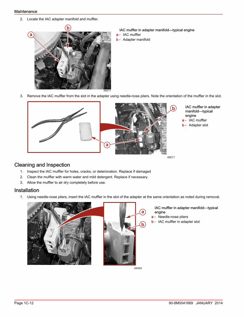
2. Locate the IAC adapter manifold and muffler.
IAC muffler in adapter manifold—typical enginea - IAC mufflerb - Adapter manifold
3. Remove the IAC muffler from the slot in the adapter using needle‑nose pliers. Note the orientation of the muffler in the slot.
IAC muffler in adaptermanifold—typicalengine
a - IAC mufflerb - Adapter slot
Cleaning and Inspection1. Inspect the IAC muffler for holes, cracks, or deterioration. Replace if damaged2. Clean the muffler with warm water and mild detergent. Replace if necessary.3. Allow the muffler to air dry completely before use.
Installation1. Using needle‑nose pliers, insert the IAC muffler in the slot of the adapter at the same orientation as noted during removal.
IAC muffler in adapter manifold—typicalengine
a - Needle‑nose pliersb - IAC muffler in adapter slot
ab
39411
aa
b
49071
49089
a
b
Maintenance
Page 1C-12 90-8M0041669 JANUARY 2014
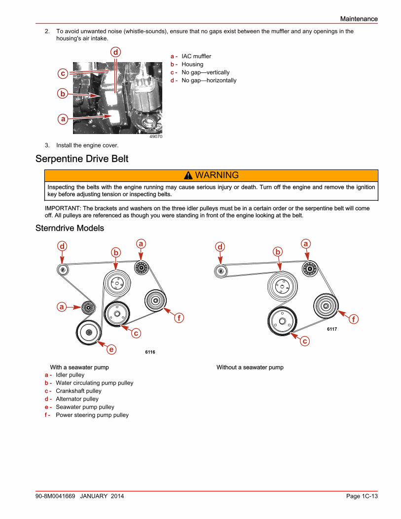
2. To avoid unwanted noise (whistle‑sounds), ensure that no gaps exist between the muffler and any openings in thehousing's air intake.
a - IAC mufflerb - Housingc - No gap—verticallyd - No gap—horizontally
3. Install the engine cover.
Serpentine Drive Belt! WARNING
Inspecting the belts with the engine running may cause serious injury or death. Turn off the engine and remove the ignitionkey before adjusting tension or inspecting belts.
IMPORTANT: The brackets and washers on the three idler pulleys must be in a certain order or the serpentine belt will comeoff. All pulleys are referenced as though you were standing in front of the engine looking at the belt.
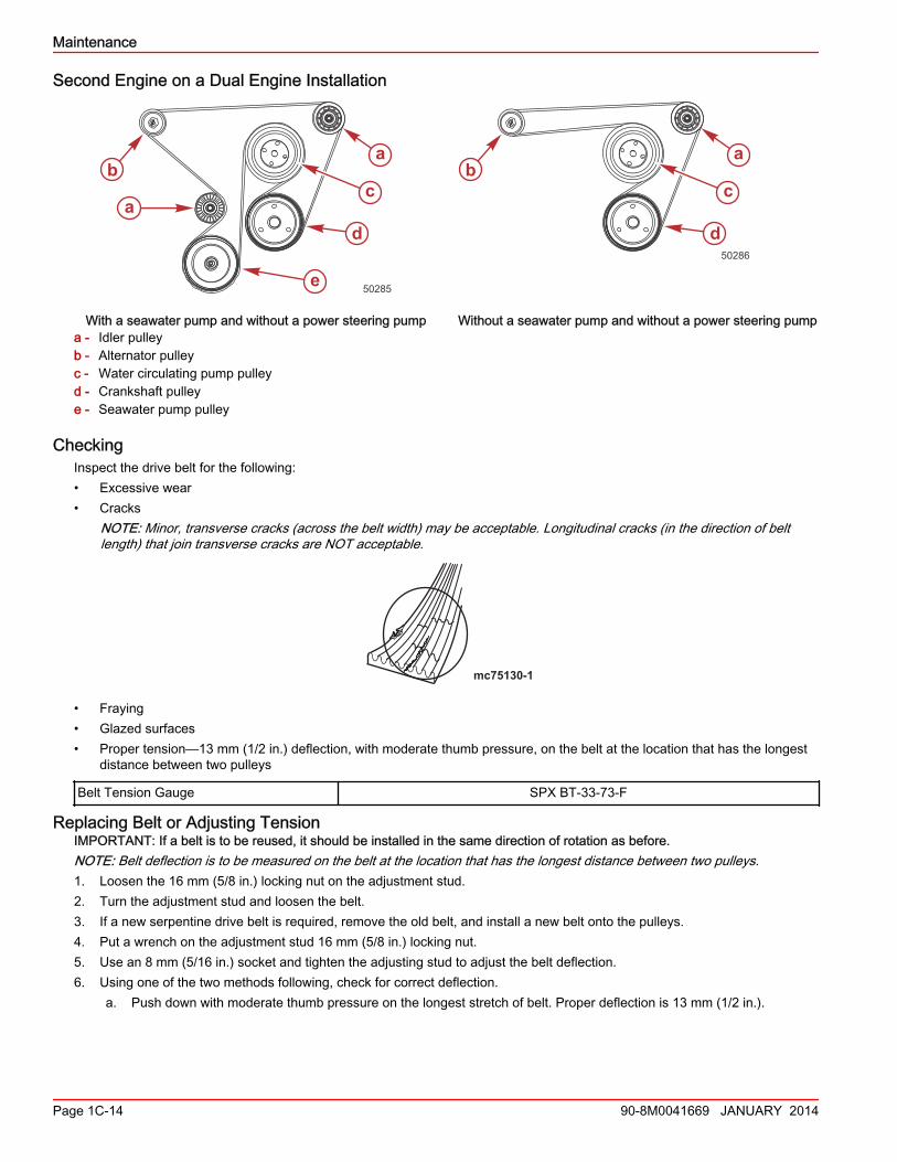
Sterndrive Models
With a seawater pump Without a seawater pumpa - Idler pulleyb - Water circulating pump pulleyc - Crankshaft pulleyd - Alternator pulleye - Seawater pump pulleyf - Power steering pump pulley
a
b
c
d
49070
6116
a
b
c
d
e
f
a
6117
f
ab
c
d
Maintenance
90-8M0041669 JANUARY 2014 Page 1C-13
Second Engine on a Dual Engine Installation
With a seawater pump and without a power steering pump Without a seawater pump and without a power steering pumpa - Idler pulleyb - Alternator pulleyc - Water circulating pump pulleyd - Crankshaft pulleye - Seawater pump pulley
CheckingInspect the drive belt for the following:• Excessive wear• Cracks
NOTE: Minor, transverse cracks (across the belt width) may be acceptable. Longitudinal cracks (in the direction of beltlength) that join transverse cracks are NOT acceptable.
mc75130-1
• Fraying• Glazed surfaces• Proper tension—13 mm (1/2 in.) deflection, with moderate thumb pressure, on the belt at the location that has the longest
distance between two pulleys
Belt Tension Gauge SPX BT‑33‑73‑F
Replacing Belt or Adjusting TensionIMPORTANT: If a belt is to be reused, it should be installed in the same direction of rotation as before.NOTE: Belt deflection is to be measured on the belt at the location that has the longest distance between two pulleys.1. Loosen the 16 mm (5/8 in.) locking nut on the adjustment stud.2. Turn the adjustment stud and loosen the belt.3. If a new serpentine drive belt is required, remove the old belt, and install a new belt onto the pulleys.4. Put a wrench on the adjustment stud 16 mm (5/8 in.) locking nut.5. Use an 8 mm (5/16 in.) socket and tighten the adjusting stud to adjust the belt deflection.6. Using one of the two methods following, check for correct deflection.
a. Push down with moderate thumb pressure on the longest stretch of belt. Proper deflection is 13 mm (1/2 in.).
a
ba
c
d
e 50285
ba
c
d50286
Maintenance
Page 1C-14 90-8M0041669 JANUARY 2014
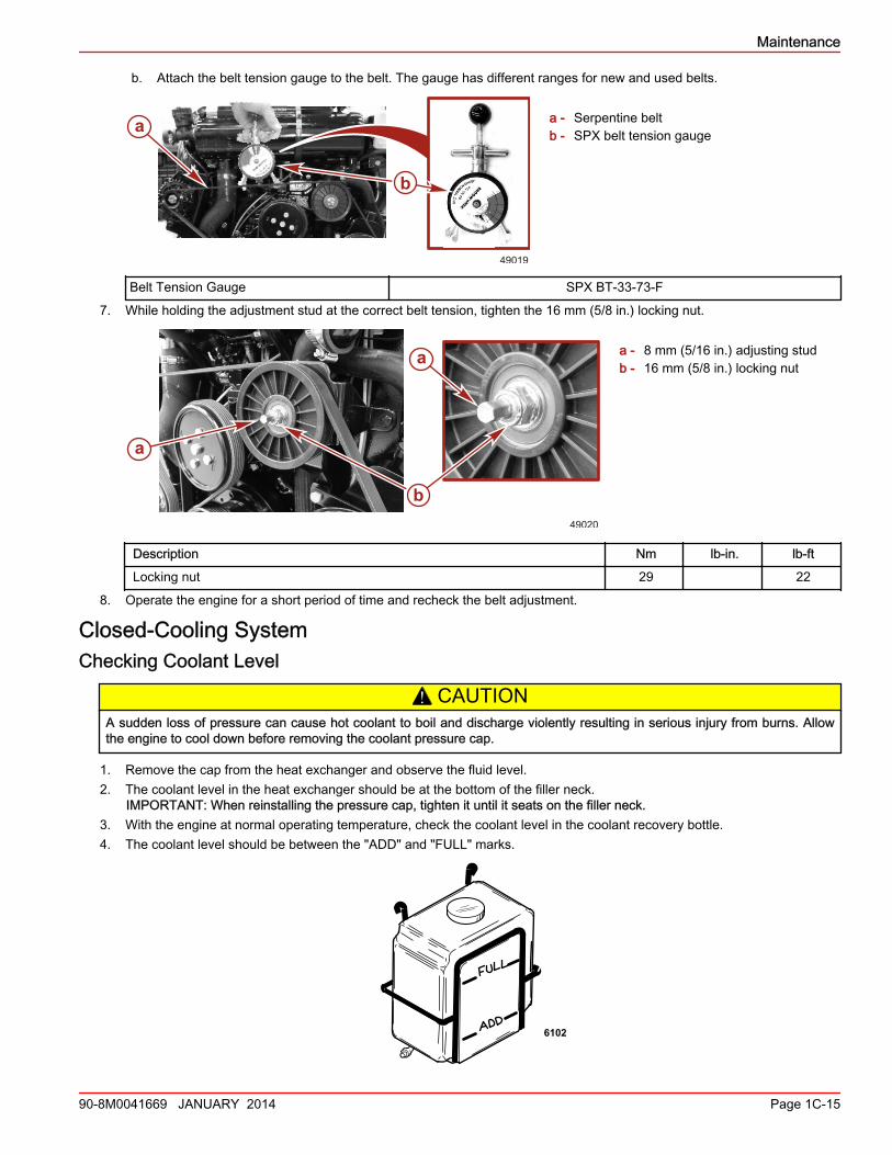
b. Attach the belt tension gauge to the belt. The gauge has different ranges for new and used belts.
a - Serpentine beltb - SPX belt tension gauge
Belt Tension Gauge SPX BT‑33‑73‑F
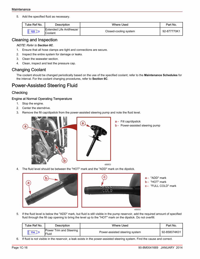
7. While holding the adjustment stud at the correct belt tension, tighten the 16 mm (5/8 in.) locking nut.
a - 8 mm (5/16 in.) adjusting studb - 16 mm (5/8 in.) locking nut
Description Nm lb‑in. lb‑ft
Locking nut 29 22
8. Operate the engine for a short period of time and recheck the belt adjustment.
Closed‑Cooling SystemChecking Coolant Level
! CAUTIONA sudden loss of pressure can cause hot coolant to boil and discharge violently resulting in serious injury from burns. Allowthe engine to cool down before removing the coolant pressure cap.
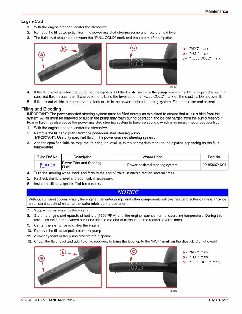
1. Remove the cap from the heat exchanger and observe the fluid level.2. The coolant level in the heat exchanger should be at the bottom of the filler neck.
IMPORTANT: When reinstalling the pressure cap, tighten it until it seats on the filler neck.3. With the engine at normal operating temperature, check the coolant level in the coolant recovery bottle.4. The coolant level should be between the "ADD" and "FULL" marks.
6102
a
bb
49019
a
bb
a
49020
Maintenance
90-8M0041669 JANUARY 2014 Page 1C-15
5. Add the specified fluid as necessary.
Tube Ref No. Description Where Used Part No.
122Extended Life Antifreeze/Coolant Closed-cooling system 92-877770K1
Cleaning and InspectionNOTE: Refer to Section 6C.1. Ensure that all hose clamps are tight and connections are secure.2. Inspect the entire system for damage or leaks.3. Clean the seawater section.4. Clean, inspect and test the pressure cap.
Changing CoolantThe coolant should be changed periodically based on the use of the specified coolant; refer to the Maintenance Schedules forthe interval. For the coolant changing procedures, refer to Section 6C.
Power‑Assisted Steering FluidCheckingEngine at Normal Operating Temperature
1. Stop the engine.2. Center the sterndrive.3. Remove the fill cap/dipstick from the power‑assisted steering pump and note the fluid level.
a - Fill cap/dipstickb - Power‑assisted steering pump
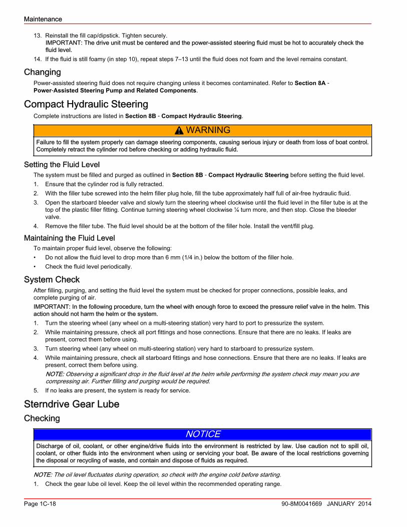
4. The fluid level should be between the "HOT" mark and the "ADD" mark on the dipstick.
a - "ADD" markb - "HOT" markc - "FULL COLD" mark
5. If the fluid level is below the "ADD" mark, but fluid is still visible in the pump reservoir, add the required amount of specifiedfluid through the fill cap opening to bring the level up to the "HOT" mark on the dipstick. Do not overfill.
Tube Ref No. Description Where Used Part No.
114Power Trim and SteeringFluid Power-assisted steering system 92-858074K01
6. If fluid is not visible in the reservoir, a leak exists in the power‑assisted steering system. Find the cause and correct.
a
b
a
48953
ca
b
48955
Maintenance
Page 1C-16 90-8M0041669 JANUARY 2014
Engine Cold1. With the engine stopped, center the sterndrive.2. Remove the fill cap/dipstick from the power‑assisted steering pump and note the fluid level.3. The fluid level should be between the "FULL COLD" mark and the bottom of the dipstick.
a - "ADD" markb - "HOT" markc - "FULL COLD" mark
4. If the fluid level is below the bottom of the dipstick, but fluid is still visible in the pump reservoir, add the required amount ofspecified fluid through the fill cap opening to bring the level up to the "FULL COLD" mark on the dipstick. Do not overfill.
5. If fluid is not visible in the reservoir, a leak exists in the power‑assisted steering system. Find the cause and correct it.
Filling and BleedingIMPORTANT: The power‑assisted steering system must be filled exactly as explained to ensure that all air is bled from thesystem. All air must be removed or fluid in the pump may foam during operation and be discharged from the pump reservoir.Foamy fluid may also cause the power‑assisted steering system to become spongy, which may result in poor boat control.1. With the engine stopped, center the sterndrive.2. Remove the fill cap/dipstick from the power‑assisted steering pump.
IMPORTANT: Use only specified fluid in the power‑assisted steering system.3. Add the specified fluid, as required, to bring the level up to the appropriate mark on the dipstick depending on the fluid
temperature.
Tube Ref No. Description Where Used Part No.
114Power Trim and SteeringFluid Power-assisted steering system 92-858074K01
4. Turn the steering wheel back and forth to the end of travel in each direction several times.5. Recheck the fluid level and add fluid, if necessary.6. Install the fill cap/dipstick. Tighten securely.
NOTICEWithout sufficient cooling water, the engine, the water pump, and other components will overheat and suffer damage. Providea sufficient supply of water to the water inlets during operation.
7. Supply cooling water to the engine.8. Start the engine and operate at fast idle (1300 RPM) until the engine reaches normal operating temperature. During this
time, turn the steering wheel back and forth to the end of travel in each direction several times.9. Center the sterndrive and stop the engine.10. Remove the fill cap/dipstick from the pump.11. Allow any foam in the pump reservoir to disperse.12. Check the fluid level and add fluid, as required, to bring the level up to the "HOT" mark on the dipstick. Do not overfill.
a - "ADD" markb - "HOT" markc - "FULL COLD" mark
ca
b
48955
ca
b
48955
Maintenance
90-8M0041669 JANUARY 2014 Page 1C-17
13. Reinstall the fill cap/dipstick. Tighten securely.IMPORTANT: The drive unit must be centered and the power‑assisted steering fluid must be hot to accurately check thefluid level.
14. If the fluid is still foamy (in step 10), repeat steps 7–13 until the fluid does not foam and the level remains constant.
ChangingPower‑assisted steering fluid does not require changing unless it becomes contaminated. Refer to Section 8A ‑Power‑Assisted Steering Pump and Related Components.
Compact Hydraulic SteeringComplete instructions are listed in Section 8B ‑ Compact Hydraulic Steering.
! WARNINGFailure to fill the system properly can damage steering components, causing serious injury or death from loss of boat control.Completely retract the cylinder rod before checking or adding hydraulic fluid.
Setting the Fluid LevelThe system must be filled and purged as outlined in Section 8B ‑ Compact Hydraulic Steering before setting the fluid level.1. Ensure that the cylinder rod is fully retracted.2. With the filler tube screwed into the helm filler plug hole, fill the tube approximately half full of air‑free hydraulic fluid.3. Open the starboard bleeder valve and slowly turn the steering wheel clockwise until the fluid level in the filler tube is at the
top of the plastic filler fitting. Continue turning steering wheel clockwise ¼ turn more, and then stop. Close the bleedervalve.
4. Remove the filler tube. The fluid level should be at the bottom of the filler hole. Install the vent/fill plug.
Maintaining the Fluid LevelTo maintain proper fluid level, observe the following:• Do not allow the fluid level to drop more than 6 mm (1/4 in.) below the bottom of the filler hole.• Check the fluid level periodically.
System CheckAfter filling, purging, and setting the fluid level the system must be checked for proper connections, possible leaks, andcomplete purging of air.IMPORTANT: In the following procedure, turn the wheel with enough force to exceed the pressure relief valve in the helm. Thisaction should not harm the helm or the system.1. Turn the steering wheel (any wheel on a multi‑steering station) very hard to port to pressurize the system.2. While maintaining pressure, check all port fittings and hose connections. Ensure that there are no leaks. If leaks are
present, correct them before using.3. Turn steering wheel (any wheel on multi‑steering station) very hard to starboard to pressurize system.4. While maintaining pressure, check all starboard fittings and hose connections. Ensure that there are no leaks. If leaks are
present, correct them before using.NOTE: Observing a significant drop in the fluid level at the helm while performing the system check may mean you arecompressing air. Further filling and purging would be required.
5. If no leaks are present, the system is ready for service.
Sterndrive Gear LubeChecking
NOTICEDischarge of oil, coolant, or other engine/drive fluids into the environment is restricted by law. Use caution not to spill oil,coolant, or other fluids into the environment when using or servicing your boat. Be aware of the local restrictions governingthe disposal or recycling of waste, and contain and dispose of fluids as required.
NOTE: The oil level fluctuates during operation, so check with the engine cold before starting.1. Check the gear lube oil level. Keep the oil level within the recommended operating range.
Maintenance
Page 1C-18 90-8M0041669 JANUARY 2014
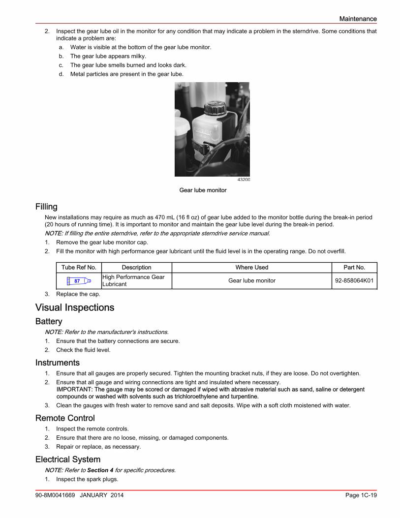
2. Inspect the gear lube oil in the monitor for any condition that may indicate a problem in the sterndrive. Some conditions thatindicate a problem are:a. Water is visible at the bottom of the gear lube monitor.b. The gear lube appears milky.c. The gear lube smells burned and looks dark.d. Metal particles are present in the gear lube.
43200
Gear lube monitor
FillingNew installations may require as much as 470 mL (16 fl oz) of gear lube added to the monitor bottle during the break‑in period(20 hours of running time). It is important to monitor and maintain the gear lube level during the break‑in period.NOTE: If filling the entire sterndrive, refer to the appropriate sterndrive service manual.1. Remove the gear lube monitor cap.2. Fill the monitor with high performance gear lubricant until the fluid level is in the operating range. Do not overfill.
Tube Ref No. Description Where Used Part No.
87High Performance GearLubricant Gear lube monitor 92-858064K01
3. Replace the cap.
Visual InspectionsBattery
NOTE: Refer to the manufacturer's instructions.1. Ensure that the battery connections are secure.2. Check the fluid level.
Instruments1. Ensure that all gauges are properly secured. Tighten the mounting bracket nuts, if they are loose. Do not overtighten.2. Ensure that all gauge and wiring connections are tight and insulated where necessary.
IMPORTANT: The gauge may be scored or damaged if wiped with abrasive material such as sand, saline or detergentcompounds or washed with solvents such as trichloroethylene and turpentine.
3. Clean the gauges with fresh water to remove sand and salt deposits. Wipe with a soft cloth moistened with water.
Remote Control1. Inspect the remote controls.2. Ensure that there are no loose, missing, or damaged components.3. Repair or replace, as necessary.
Electrical SystemNOTE: Refer to Section 4 for specific procedures.1. Inspect the spark plugs.
Maintenance
90-8M0041669 JANUARY 2014 Page 1C-19
2. Inspect the spark plug wires.3. Inspect the distributor cap.4. Inspect the entire electrical system for loose, damaged, or corroded fasteners.5. Repair or replace as necessary.
Exhaust SystemNOTE: Refer to Section 7.1. Ensure that all hose clamps are tight and connections are secure.2. Inspect the entire system for damage or leaks.3. Repair or replace as necessary.
Seawater PumpNOTE: Refer to Section 6A.Inspect the seawater pump components. Replace as necessary.
Steering System Lubrication! WARNING
Incorrect cable lubrication can cause hydraulic lock, leading to serious injury or death from loss of boat control. Completelyretract the end of the steering cable before applying lubricant.
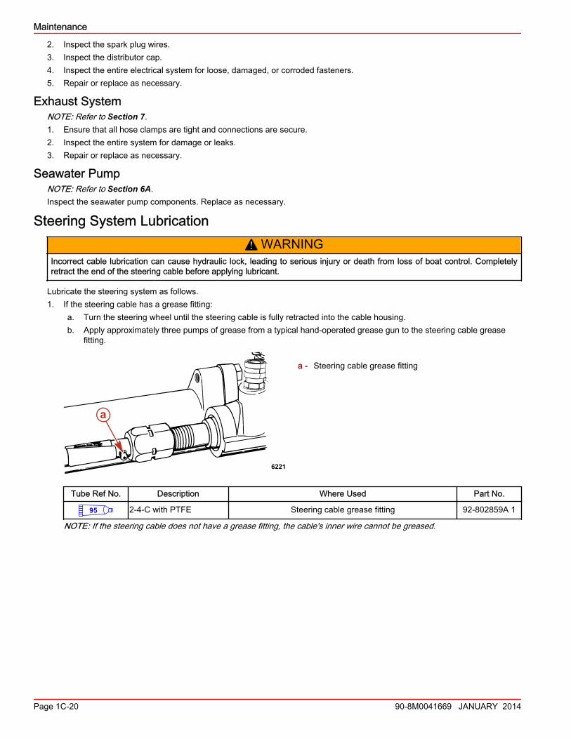
Lubricate the steering system as follows.1. If the steering cable has a grease fitting:
a. Turn the steering wheel until the steering cable is fully retracted into the cable housing.b. Apply approximately three pumps of grease from a typical hand‑operated grease gun to the steering cable grease
fitting.
a - Steering cable grease fitting
Tube Ref No. Description Where Used Part No.
95 2-4-C with PTFE Steering cable grease fitting 92-802859A 1
NOTE: If the steering cable does not have a grease fitting, the cable's inner wire cannot be greased.
6221
a
Maintenance
Page 1C-20 90-8M0041669 JANUARY 2014
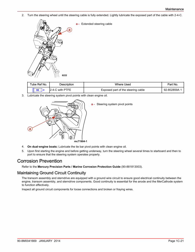
2. Turn the steering wheel until the steering cable is fully extended. Lightly lubricate the exposed part of the cable with 2‑4‑C.
a - Extended steering cable
Tube Ref No. Description Where Used Part No.
95 2-4-C with PTFE Exposed part of the steering cable 92-802859A 1
3. Lubricate the steering system pivot points with clean engine oil.
a - Steering system pivot points
4. On dual‑engine boats: Lubricate the tie bar pivot points with clean engine oil.5. Upon first starting the engine and before getting underway, turn the steering wheel several times to starboard and then to
port to ensure that the steering system operates properly.
Corrosion PreventionRefer to the Mercury Precision Parts / Marine Corrosion Protection Guide (90‑881813003).
Maintaining Ground Circuit ContinuityThe transom assembly and sterndrive are equipped with a ground wire circuit to ensure good electrical continuity between theengine, transom assembly, and sterndrive components. Good continuity is essential for the anode and the MerCathode systemto function effectively.Inspect all ground circuit components for loose connections and broken or fraying wires.
a
6222
mc71904-1
a
Maintenance
90-8M0041669 JANUARY 2014 Page 1C-21
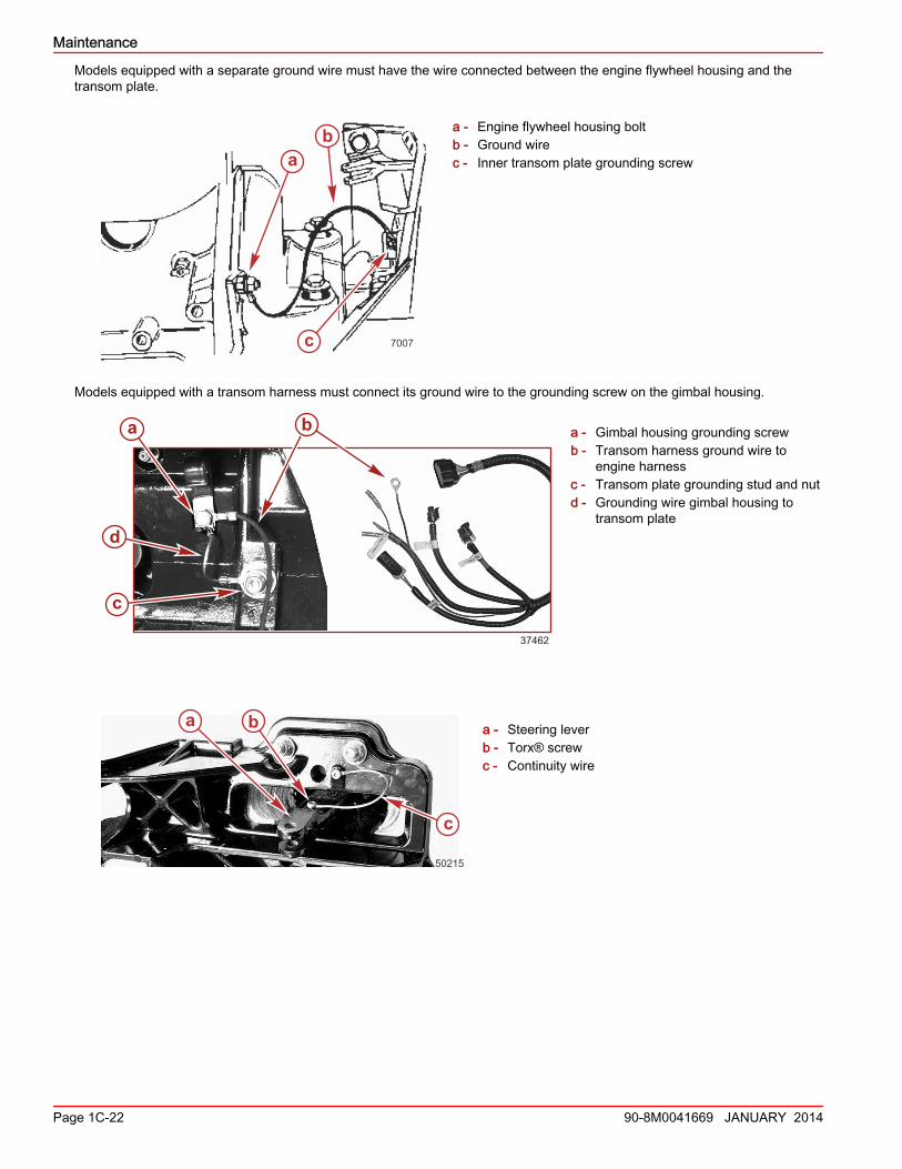
Models equipped with a separate ground wire must have the wire connected between the engine flywheel housing and thetransom plate.
a - Engine flywheel housing boltb - Ground wirec - Inner transom plate grounding screw
Models equipped with a transom harness must connect its ground wire to the grounding screw on the gimbal housing.
a - Gimbal housing grounding screwb - Transom harness ground wire to
engine harnessc - Transom plate grounding stud and nutd - Grounding wire gimbal housing to
transom plate
a - Steering leverb - Torx® screwc - Continuity wire
ab
c 7007
37462
a
d
bb
c
a b
c
50215
Maintenance
Page 1C-22 90-8M0041669 JANUARY 2014
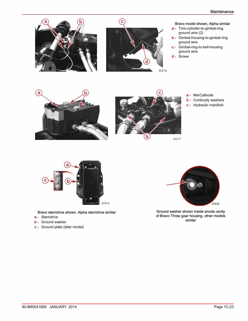
Bravo model shown, Alpha similara - Trim‑cylinder‑to‑gimbal‑ring
ground wire (2)b - Gimbal‑housing‑to‑gimbal‑ring
ground wirec - Gimbal‑ring‑to‑bell‑housing
ground wired - Screw
a - MerCathodeb - Continuity washersc - Hydraulic manifold
Bravo sterndrive shown, Alpha sterndrive similara - Sterndriveb - Ground washerc - Ground plate (later model)
37513
c
a
b
37632
Ground washer shown inside anode cavityof Bravo Three gear housing, other models
similar
ba c
d50216
ba
50217b
c
Maintenance
90-8M0041669 JANUARY 2014 Page 1C-23
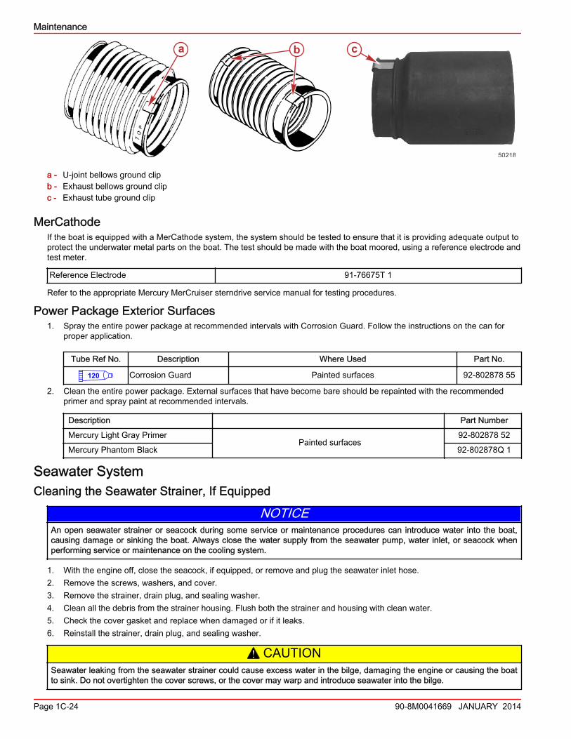
a - U‑joint bellows ground clipb - Exhaust bellows ground clipc - Exhaust tube ground clip
MerCathodeIf the boat is equipped with a MerCathode system, the system should be tested to ensure that it is providing adequate output toprotect the underwater metal parts on the boat. The test should be made with the boat moored, using a reference electrode andtest meter.
Reference Electrode 91‑76675T 1
Refer to the appropriate Mercury MerCruiser sterndrive service manual for testing procedures.
Power Package Exterior Surfaces1. Spray the entire power package at recommended intervals with Corrosion Guard. Follow the instructions on the can for
proper application.
Tube Ref No. Description Where Used Part No.
120 Corrosion Guard Painted surfaces 92-802878 55
2. Clean the entire power package. External surfaces that have become bare should be repainted with the recommendedprimer and spray paint at recommended intervals.
Description Part Number
Mercury Light Gray PrimerPainted surfaces
92‑802878 52
Mercury Phantom Black 92‑802878Q 1
Seawater SystemCleaning the Seawater Strainer, If Equipped
NOTICEAn open seawater strainer or seacock during some service or maintenance procedures can introduce water into the boat,causing damage or sinking the boat. Always close the water supply from the seawater pump, water inlet, or seacock whenperforming service or maintenance on the cooling system.
1. With the engine off, close the seacock, if equipped, or remove and plug the seawater inlet hose.2. Remove the screws, washers, and cover.3. Remove the strainer, drain plug, and sealing washer.4. Clean all the debris from the strainer housing. Flush both the strainer and housing with clean water.5. Check the cover gasket and replace when damaged or if it leaks.6. Reinstall the strainer, drain plug, and sealing washer.
! CAUTIONSeawater leaking from the seawater strainer could cause excess water in the bilge, damaging the engine or causing the boatto sink. Do not overtighten the cover screws, or the cover may warp and introduce seawater into the bilge.
a b c
50218
Maintenance
Page 1C-24 90-8M0041669 JANUARY 2014
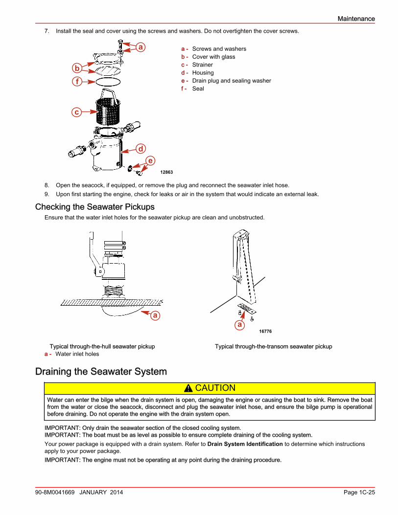
7. Install the seal and cover using the screws and washers. Do not overtighten the cover screws.
a - Screws and washersb - Cover with glassc - Strainerd - Housinge - Drain plug and sealing washerf - Seal
8. Open the seacock, if equipped, or remove the plug and reconnect the seawater inlet hose.9. Upon first starting the engine, check for leaks or air in the system that would indicate an external leak.
Checking the Seawater PickupsEnsure that the water inlet holes for the seawater pickup are clean and unobstructed.
Typical through-the-hull seawater pickup Typical through-the-transom seawater pickupa - Water inlet holes
Draining the Seawater System! CAUTION
Water can enter the bilge when the drain system is open, damaging the engine or causing the boat to sink. Remove the boatfrom the water or close the seacock, disconnect and plug the seawater inlet hose, and ensure the bilge pump is operationalbefore draining. Do not operate the engine with the drain system open.
IMPORTANT: Only drain the seawater section of the closed cooling system.IMPORTANT: The boat must be as level as possible to ensure complete draining of the cooling system.Your power package is equipped with a drain system. Refer to Drain System Identification to determine which instructionsapply to your power package.IMPORTANT: The engine must not be operating at any point during the draining procedure.
a
b
c
de
f
12863
aa
16776
Maintenance
90-8M0041669 JANUARY 2014 Page 1C-25
IMPORTANT: Mercury MerCruiser requires that propylene glycol antifreeze, mixed to the manufacturer's instructions, be usedin the seawater section of the cooling system for freezing temperatures or extended storage. Ensure that the propylene glycolantifreeze contains a rust inhibitor and is recommended for use in marine engines. Be certain to follow the propylene glycolmanufacturer's recommendations.
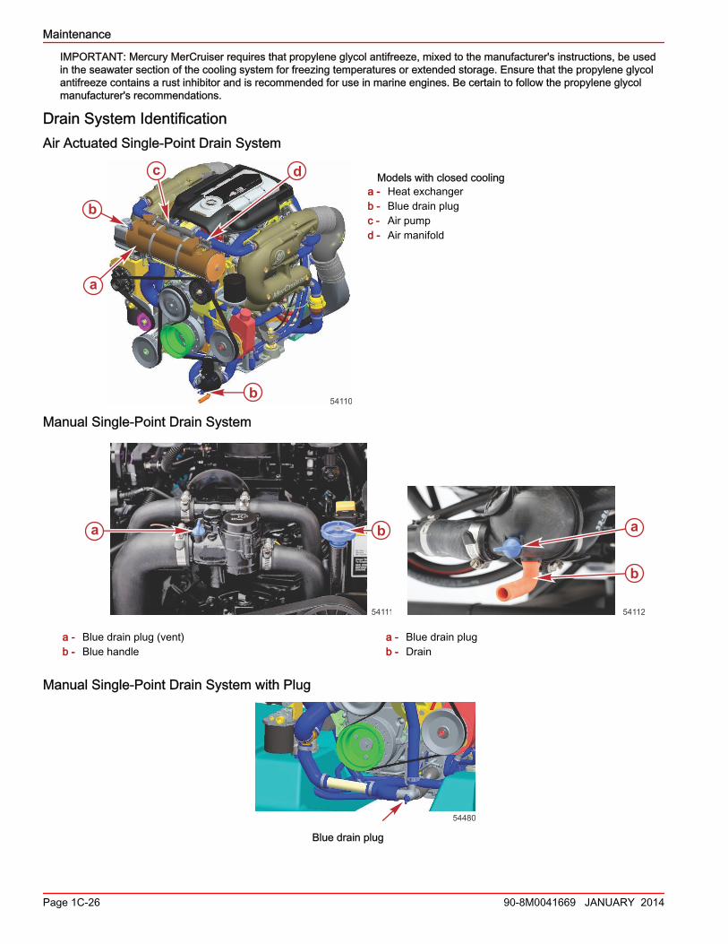
Drain System IdentificationAir Actuated Single-Point Drain System
Models with closed coolinga - Heat exchangerb - Blue drain plugc - Air pumpd - Air manifold
Manual Single-Point Drain System
a - Blue drain plug (vent)b - Blue handle
a b
54111
a - Blue drain plugb - Drain
54112
a
b
Manual Single-Point Drain System with Plug
54480
Blue drain plug
a
b
c
b
d
54110
Maintenance
Page 1C-26 90-8M0041669 JANUARY 2014
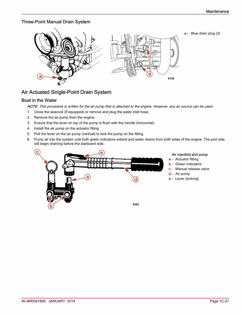
Three-Point Manual Drain System
a - Blue drain plug (3)
Air Actuated Single‑Point Drain SystemBoat in the Water
NOTE: This procedure is written for the air pump that is attached to the engine. However, any air source can be used.1. Close the seacock (if equipped) or remove and plug the water inlet hose.2. Remove the air pump from the engine.3. Ensure that the lever on top of the pump is flush with the handle (horizontal).4. Install the air pump on the actuator fitting.5. Pull the lever on the air pump (vertical) to lock the pump on the fitting.6. Pump air into the system until both green indicators extend and water drains from both sides of the engine. The port side
will begin draining before the starboard side.
Air manifold and pumpa - Actuator fittingb - Green indicatorsc - Manual release valved - Air pumpe - Lever (locking)
a a6126
8293b
d
e
a
c
Maintenance
90-8M0041669 JANUARY 2014 Page 1C-27
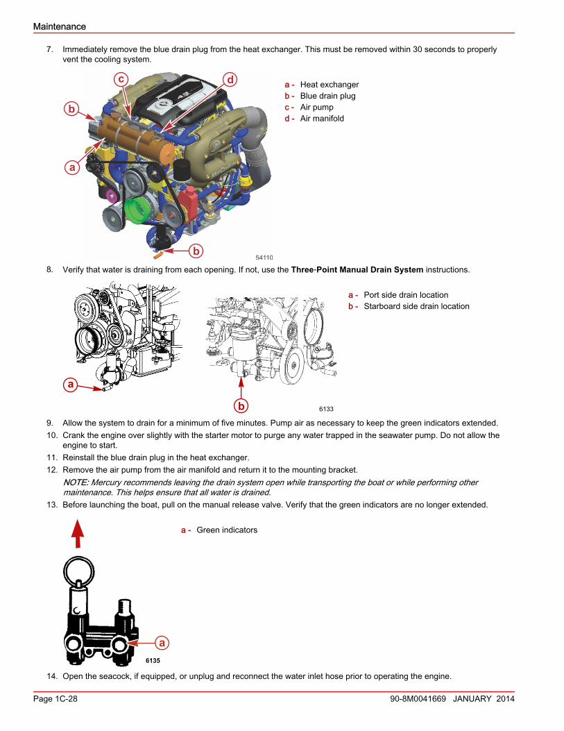
7. Immediately remove the blue drain plug from the heat exchanger. This must be removed within 30 seconds to properlyvent the cooling system.
a - Heat exchangerb - Blue drain plugc - Air pumpd - Air manifold
8. Verify that water is draining from each opening. If not, use the Three‑Point Manual Drain System instructions.
a - Port side drain locationb - Starboard side drain location
9. Allow the system to drain for a minimum of five minutes. Pump air as necessary to keep the green indicators extended.10. Crank the engine over slightly with the starter motor to purge any water trapped in the seawater pump. Do not allow the
engine to start.11. Reinstall the blue drain plug in the heat exchanger.12. Remove the air pump from the air manifold and return it to the mounting bracket.
NOTE: Mercury recommends leaving the drain system open while transporting the boat or while performing othermaintenance. This helps ensure that all water is drained.
13. Before launching the boat, pull on the manual release valve. Verify that the green indicators are no longer extended.
a - Green indicators
14. Open the seacock, if equipped, or unplug and reconnect the water inlet hose prior to operating the engine.
a
b
c
b
d
54110
a
b 6133
a6135
Maintenance
Page 1C-28 90-8M0041669 JANUARY 2014
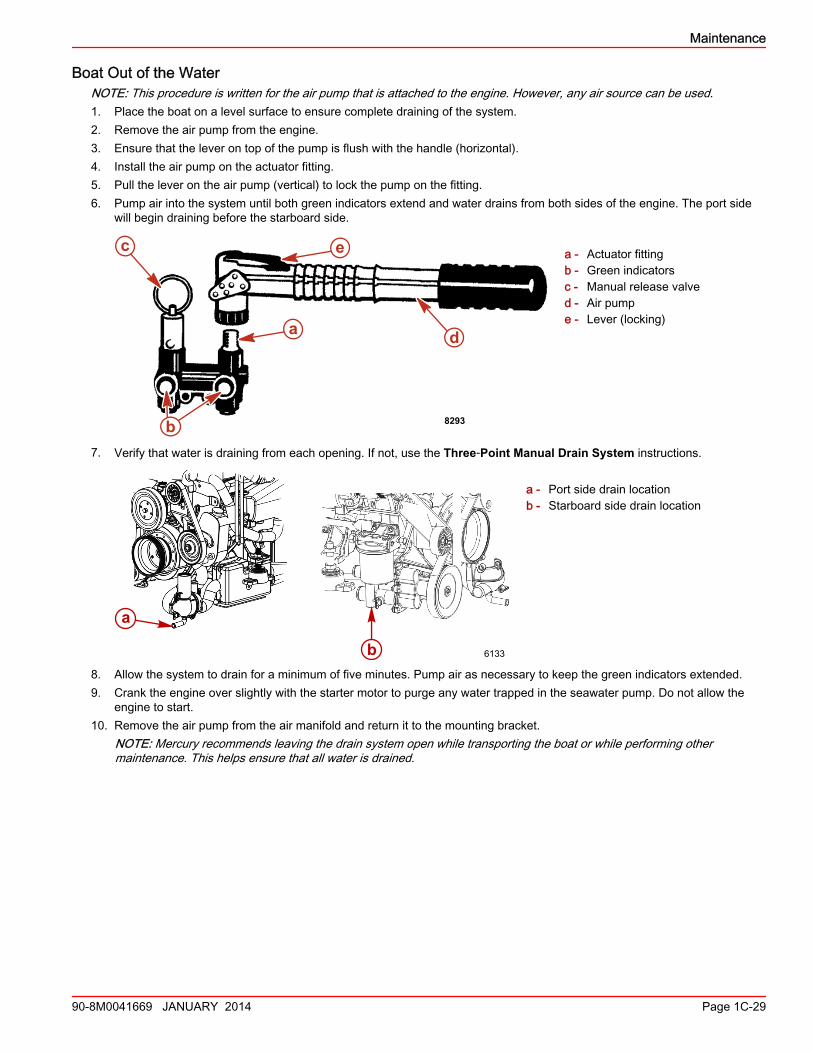
Boat Out of the WaterNOTE: This procedure is written for the air pump that is attached to the engine. However, any air source can be used.1. Place the boat on a level surface to ensure complete draining of the system.2. Remove the air pump from the engine.3. Ensure that the lever on top of the pump is flush with the handle (horizontal).4. Install the air pump on the actuator fitting.5. Pull the lever on the air pump (vertical) to lock the pump on the fitting.6. Pump air into the system until both green indicators extend and water drains from both sides of the engine. The port side
will begin draining before the starboard side.
a - Actuator fittingb - Green indicatorsc - Manual release valved - Air pumpe - Lever (locking)
7. Verify that water is draining from each opening. If not, use the Three‑Point Manual Drain System instructions.
a - Port side drain locationb - Starboard side drain location
8. Allow the system to drain for a minimum of five minutes. Pump air as necessary to keep the green indicators extended.9. Crank the engine over slightly with the starter motor to purge any water trapped in the seawater pump. Do not allow the
engine to start.10. Remove the air pump from the air manifold and return it to the mounting bracket.
NOTE: Mercury recommends leaving the drain system open while transporting the boat or while performing othermaintenance. This helps ensure that all water is drained.
8293b
d
e
a
c
a
b 6133
Maintenance
90-8M0041669 JANUARY 2014 Page 1C-29
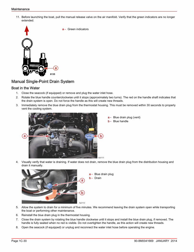
11. Before launching the boat, pull the manual release valve on the air manifold. Verify that the green indicators are no longerextended.
a - Green indicators
Manual Single‑Point Drain SystemBoat in the Water
1. Close the seacock (if equipped) or remove and plug the water inlet hose.2. Rotate the blue handle counterclockwise until it stops (approximately two turns). The red on the handle shaft indicates that
the drain system is open. Do not force the handle as this will create new threads.3. Immediately remove the blue drain plug from the thermostat housing. This must be removed within 30 seconds to properly
vent the cooling system.
a - Blue drain plug (vent)b - Blue handle
4. Visually verify that water is draining. If water does not drain, remove the blue drain plug from the distribution housing anddrain it manually.
a - Blue drain plugb - Drain
5. Allow the system to drain for a minimum of five minutes. We recommend leaving the drain system open while transportingthe boat or performing other maintenance.
6. Reinstall the blue drain plug in the thermostat housing.7. Close the drain system by rotating the blue handle clockwise until it stops and install the blue drain plug, if removed. The
handle is fully seated when no red is visible. Do not overtighten the handle, as this action will create new threads.8. Open the seacock (if equipped) or unplug and reconnect the water inlet hose before operating the engine.
a6135
a b
54111
54112
a
b
Maintenance
Page 1C-30 90-8M0041669 JANUARY 2014
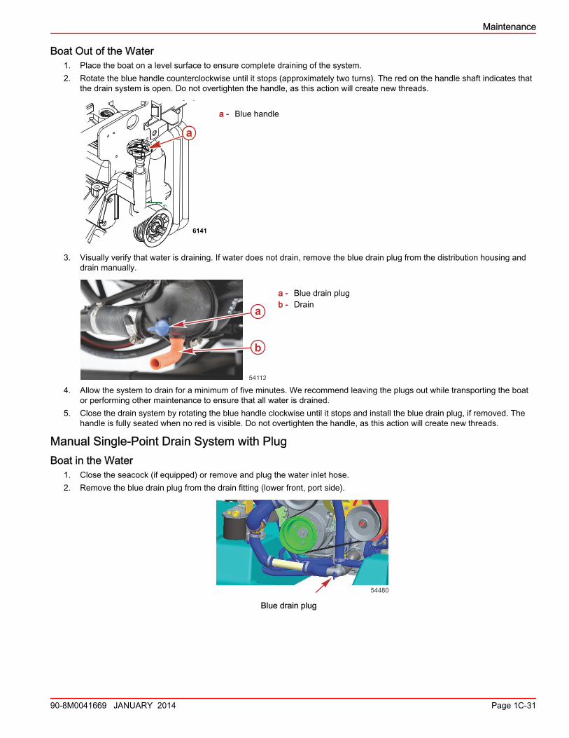
Boat Out of the Water1. Place the boat on a level surface to ensure complete draining of the system.2. Rotate the blue handle counterclockwise until it stops (approximately two turns). The red on the handle shaft indicates that
the drain system is open. Do not overtighten the handle, as this action will create new threads.
a - Blue handle
3. Visually verify that water is draining. If water does not drain, remove the blue drain plug from the distribution housing anddrain manually.
a - Blue drain plugb - Drain
4. Allow the system to drain for a minimum of five minutes. We recommend leaving the plugs out while transporting the boator performing other maintenance to ensure that all water is drained.
5. Close the drain system by rotating the blue handle clockwise until it stops and install the blue drain plug, if removed. Thehandle is fully seated when no red is visible. Do not overtighten the handle, as this action will create new threads.
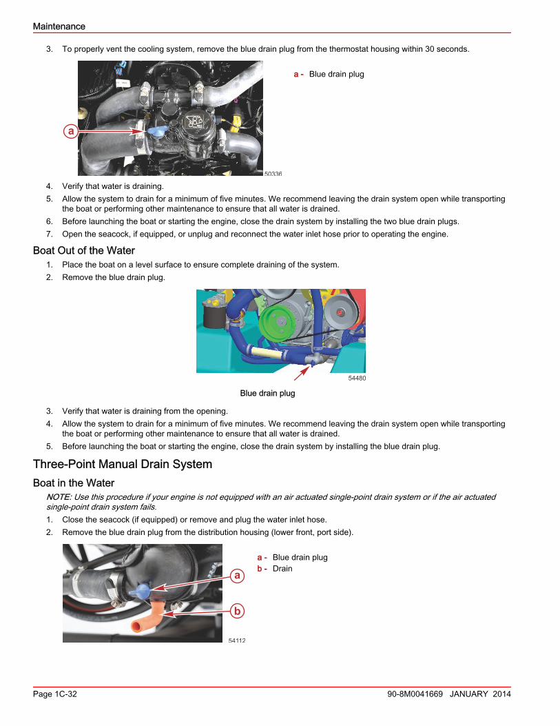
Manual Single‑Point Drain System with PlugBoat in the Water
1. Close the seacock (if equipped) or remove and plug the water inlet hose.2. Remove the blue drain plug from the drain fitting (lower front, port side).
54480
Blue drain plug
a
6141
54112
a
b
Maintenance
90-8M0041669 JANUARY 2014 Page 1C-31
3. To properly vent the cooling system, remove the blue drain plug from the thermostat housing within 30 seconds.
a - Blue drain plug
4. Verify that water is draining.5. Allow the system to drain for a minimum of five minutes. We recommend leaving the drain system open while transporting
the boat or performing other maintenance to ensure that all water is drained.6. Before launching the boat or starting the engine, close the drain system by installing the two blue drain plugs.7. Open the seacock, if equipped, or unplug and reconnect the water inlet hose prior to operating the engine.
Boat Out of the Water1. Place the boat on a level surface to ensure complete draining of the system.2. Remove the blue drain plug.
54480
Blue drain plug
3. Verify that water is draining from the opening.4. Allow the system to drain for a minimum of five minutes. We recommend leaving the drain system open while transporting
the boat or performing other maintenance to ensure that all water is drained.5. Before launching the boat or starting the engine, close the drain system by installing the blue drain plug.
Three‑Point Manual Drain SystemBoat in the Water
NOTE: Use this procedure if your engine is not equipped with an air actuated single‑point drain system or if the air actuatedsingle‑point drain system fails.1. Close the seacock (if equipped) or remove and plug the water inlet hose.2. Remove the blue drain plug from the distribution housing (lower front, port side).
a - Blue drain plugb - Drain
a
50336
54112
a
b
Maintenance
Page 1C-32 90-8M0041669 JANUARY 2014
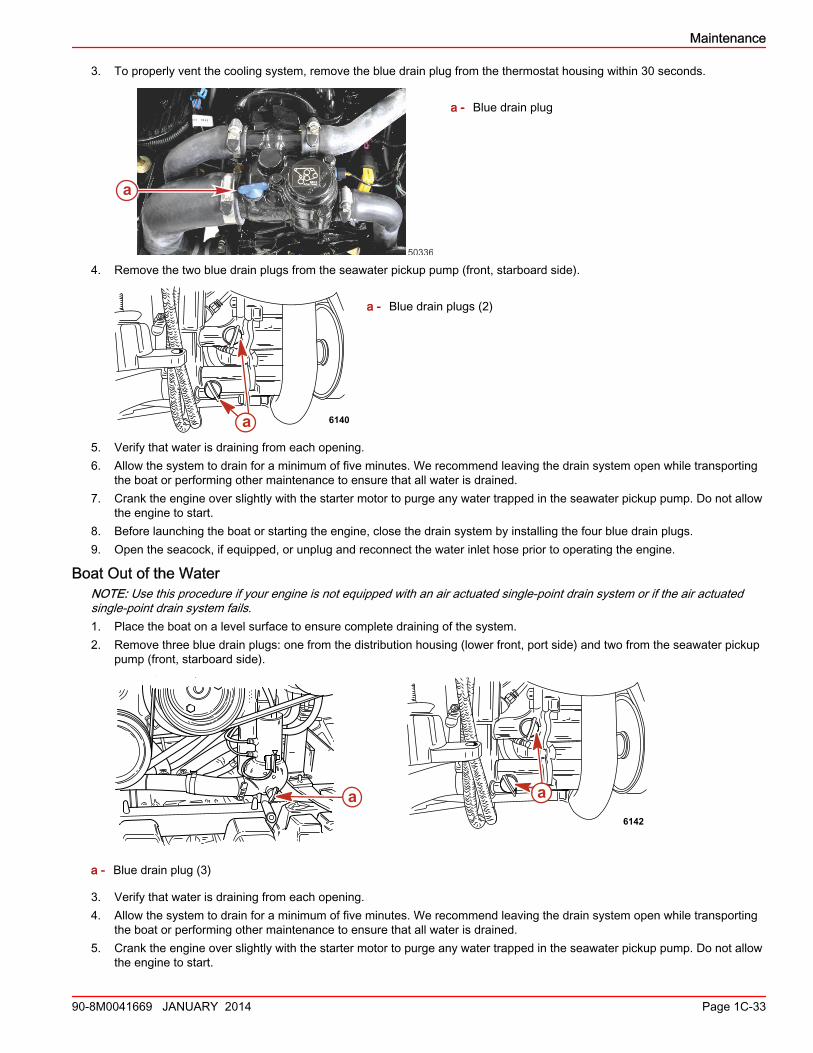
3. To properly vent the cooling system, remove the blue drain plug from the thermostat housing within 30 seconds.
a - Blue drain plug
4. Remove the two blue drain plugs from the seawater pickup pump (front, starboard side).
a - Blue drain plugs (2)
5. Verify that water is draining from each opening.6. Allow the system to drain for a minimum of five minutes. We recommend leaving the drain system open while transporting
the boat or performing other maintenance to ensure that all water is drained.7. Crank the engine over slightly with the starter motor to purge any water trapped in the seawater pickup pump. Do not allow
the engine to start.8. Before launching the boat or starting the engine, close the drain system by installing the four blue drain plugs.9. Open the seacock, if equipped, or unplug and reconnect the water inlet hose prior to operating the engine.
Boat Out of the WaterNOTE: Use this procedure if your engine is not equipped with an air actuated single‑point drain system or if the air actuatedsingle‑point drain system fails.1. Place the boat on a level surface to ensure complete draining of the system.2. Remove three blue drain plugs: one from the distribution housing (lower front, port side) and two from the seawater pickup
pump (front, starboard side).
a - Blue drain plug (3)
3. Verify that water is draining from each opening.4. Allow the system to drain for a minimum of five minutes. We recommend leaving the drain system open while transporting
the boat or performing other maintenance to ensure that all water is drained.5. Crank the engine over slightly with the starter motor to purge any water trapped in the seawater pickup pump. Do not allow
the engine to start.
a
50336
a 6140
aa6142
Maintenance
90-8M0041669 JANUARY 2014 Page 1C-33
6. Before launching the boat or starting the engine, close the drain system by installing the three blue drain plugs.
Flushing the Power Package (Alpha)Your boat comes equipped with through‑the‑sterndrive water pickups. Refer to Sterndrive Water Pickups for the flushingprocedure.IMPORTANT: Alpha engines that have the sterndrive water inlet blocked off at the gimbal housing and use a through‑the‑hullwater inlet need a supply of cooling water available to both the sterndrive and the engine during operation.
Flushing AttachmentsFlushing Device 91‑44357Q 2
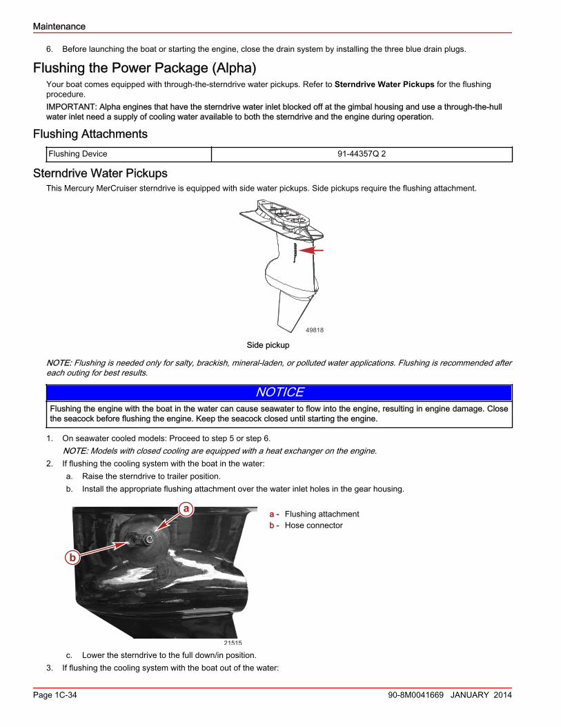
Sterndrive Water PickupsThis Mercury MerCruiser sterndrive is equipped with side water pickups. Side pickups require the flushing attachment.
49818
Side pickup
NOTE: Flushing is needed only for salty, brackish, mineral‑laden, or polluted water applications. Flushing is recommended aftereach outing for best results.
NOTICEFlushing the engine with the boat in the water can cause seawater to flow into the engine, resulting in engine damage. Closethe seacock before flushing the engine. Keep the seacock closed until starting the engine.
1. On seawater cooled models: Proceed to step 5 or step 6.NOTE: Models with closed cooling are equipped with a heat exchanger on the engine.
2. If flushing the cooling system with the boat in the water:a. Raise the sterndrive to trailer position.b. Install the appropriate flushing attachment over the water inlet holes in the gear housing.
a - Flushing attachmentb - Hose connector
c. Lower the sterndrive to the full down/in position.3. If flushing the cooling system with the boat out of the water:
21515
a
b
Maintenance
Page 1C-34 90-8M0041669 JANUARY 2014
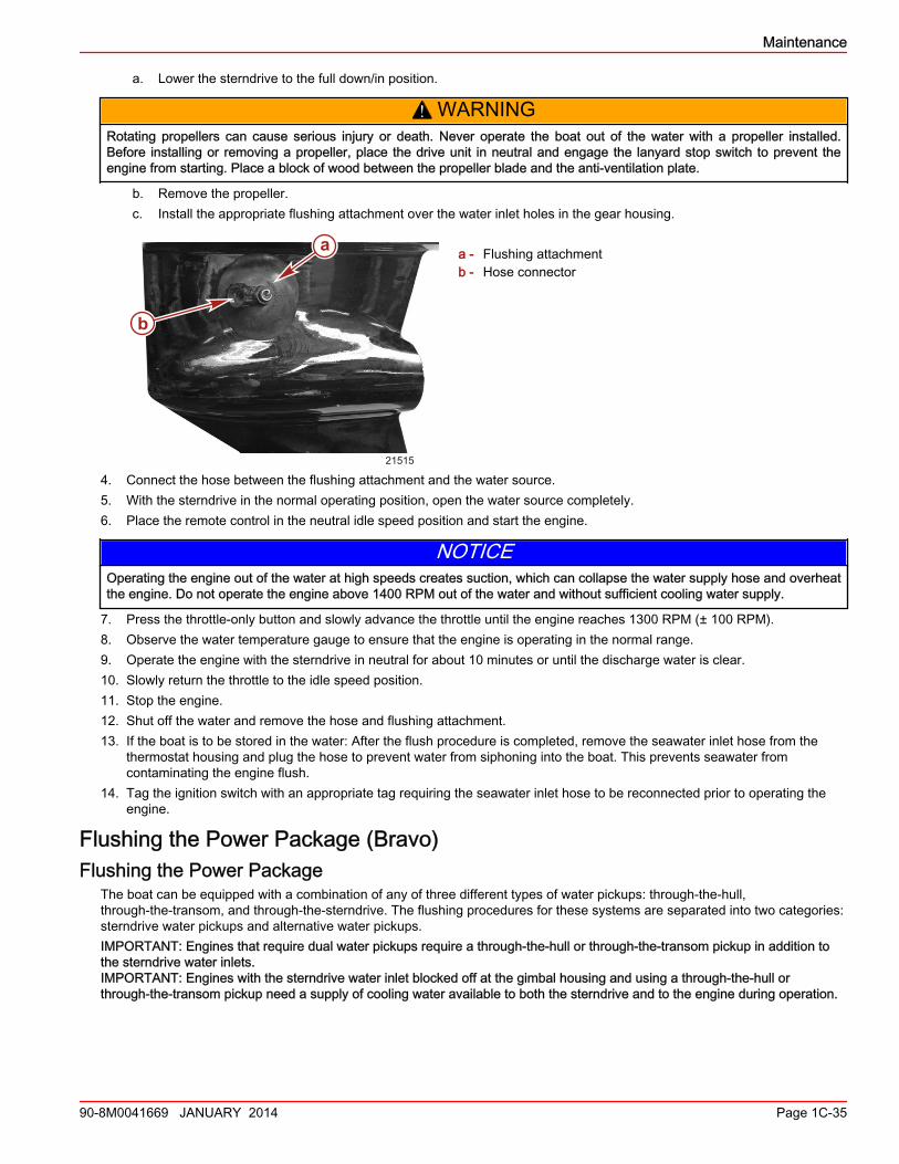
a. Lower the sterndrive to the full down/in position.
! WARNINGRotating propellers can cause serious injury or death. Never operate the boat out of the water with a propeller installed.Before installing or removing a propeller, place the drive unit in neutral and engage the lanyard stop switch to prevent theengine from starting. Place a block of wood between the propeller blade and the anti‑ventilation plate.
b. Remove the propeller.c. Install the appropriate flushing attachment over the water inlet holes in the gear housing.
a - Flushing attachmentb - Hose connector
4. Connect the hose between the flushing attachment and the water source.5. With the sterndrive in the normal operating position, open the water source completely.6. Place the remote control in the neutral idle speed position and start the engine.
NOTICEOperating the engine out of the water at high speeds creates suction, which can collapse the water supply hose and overheatthe engine. Do not operate the engine above 1400 RPM out of the water and without sufficient cooling water supply.
7. Press the throttle‑only button and slowly advance the throttle until the engine reaches 1300 RPM (± 100 RPM).8. Observe the water temperature gauge to ensure that the engine is operating in the normal range.9. Operate the engine with the sterndrive in neutral for about 10 minutes or until the discharge water is clear.10. Slowly return the throttle to the idle speed position.11. Stop the engine.12. Shut off the water and remove the hose and flushing attachment.13. If the boat is to be stored in the water: After the flush procedure is completed, remove the seawater inlet hose from the
thermostat housing and plug the hose to prevent water from siphoning into the boat. This prevents seawater fromcontaminating the engine flush.
14. Tag the ignition switch with an appropriate tag requiring the seawater inlet hose to be reconnected prior to operating theengine.
Flushing the Power Package (Bravo)Flushing the Power Package
The boat can be equipped with a combination of any of three different types of water pickups: through‑the‑hull,through‑the‑transom, and through‑the‑sterndrive. The flushing procedures for these systems are separated into two categories:sterndrive water pickups and alternative water pickups.IMPORTANT: Engines that require dual water pickups require a through‑the‑hull or through‑the‑transom pickup in addition tothe sterndrive water inlets.IMPORTANT: Engines with the sterndrive water inlet blocked off at the gimbal housing and using a through‑the‑hull orthrough‑the‑transom pickup need a supply of cooling water available to both the sterndrive and to the engine during operation.
21515
a
b
Maintenance
90-8M0041669 JANUARY 2014 Page 1C-35
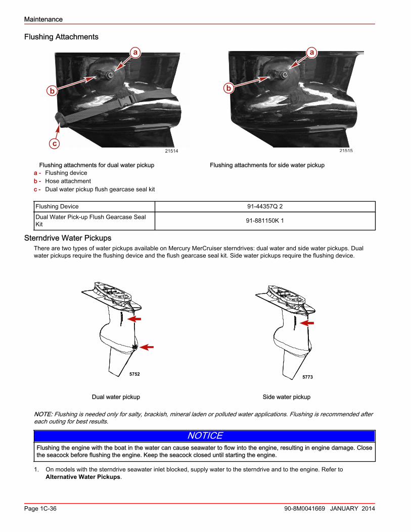
Flushing Attachments
Flushing attachments for dual water pickup Flushing attachments for side water pickupa - Flushing deviceb - Hose attachmentc - Dual water pickup flush gearcase seal kit
Flushing Device 91‑44357Q 2
Dual Water Pick‑up Flush Gearcase SealKit 91‑881150K 1
Sterndrive Water PickupsThere are two types of water pickups available on Mercury MerCruiser sterndrives: dual water and side water pickups. Dualwater pickups require the flushing device and the flush gearcase seal kit. Side water pickups require the flushing device.
5752
Dual water pickup
5773
Side water pickup
NOTE: Flushing is needed only for salty, brackish, mineral laden or polluted water applications. Flushing is recommended aftereach outing for best results.
NOTICEFlushing the engine with the boat in the water can cause seawater to flow into the engine, resulting in engine damage. Closethe seacock before flushing the engine. Keep the seacock closed until starting the engine.
1. On models with the sterndrive seawater inlet blocked, supply water to the sterndrive and to the engine. Refer toAlternative Water Pickups.
a
b
c21514 21515
a
b
Maintenance
Page 1C-36 90-8M0041669 JANUARY 2014
2. On models using the sterndrive seawater inlet and a through‑the‑hull or through‑the‑transom alternative water pickup,supply water to only the sterndrive by taking the following steps to block, or disconnect and block, the hose from thealternative seawater pickup pump inlet Y‑fitting.a. If equipped with a seacock, close the seacock in the hose from the alternative water pickup.b. If not equipped with a seacock, disconnect the hose from the alternative water pickup and plug both ends.c. If there is not a hose running to the transom, refer to Alternative Water Pickups.
3. On models using the sterndrive water pickups for water supply: proceed to step 4 or step 5.4. If flushing the cooling system with the boat in the water:
a. Raise the sterndrive to trailer position.b. Install the appropriate flushing attachment over the water inlet holes in the gear housing.c. Lower sterndrive to full down (in) position.
5. If flushing the cooling system with the boat out of the water:a. Lower the sterndrive to full down (in) position.
! WARNINGRotating propellers can cause serious injury or death. Never operate the boat out of the water with a propeller installed.Before installing or removing a propeller, place the drive unit in neutral and engage the lanyard stop switch to prevent theengine from starting. Place a block of wood between the propeller blade and the anti‑ventilation plate.
b. Remove propeller.c. Install the appropriate flushing attachment over the water inlet holes in the gear housing.
6. Connect hose between flushing attachment and water source.7. With the sterndrive in normal operating position, fully open the water source.8. Place the remote control in the neutral idle speed position and start the engine.
NOTICEOperating the engine out of the water at high speeds creates suction, which can collapse the water supply hose and overheatthe engine. Do not operate the engine above 1400 RPM out of the water and without sufficient cooling water supply.
9. Press the throttle‑only button and slowly advance the throttle until the engine reaches 1300 RPM (± 100 RPM).10. Observe the water temperature gauge to ensure that the engine is operating in the normal range.11. Operate the engine with the sterndrive in neutral for about 10 minutes or until the discharge water is clear.12. Slowly return the throttle to idle speed position.13. Stop the engine.14. Shut off the water and remove the flushing attachment.15. Remove the seawater inlet hose from the seawater pump and plug the hose to prevent water from siphoning into the
engine.16. Tag the ignition switch with an appropriate tag requiring the seawater inlet hose to be reconnected prior to operating the
engine.
Alternative Water PickupsIMPORTANT: Two water sources are needed for this procedure.NOTE: Flushing is needed only for salty, brackish, mineral‑laden or polluted water applications. Flushing is recommended aftereach outing for best results.IMPORTANT: Models with the sterndrive water inlet blocked off at the gimbal housing and using a through‑hull water inlet needa supply of cooling water available to both the sterndrive and to the engine during operation.1. If flushing the cooling system with the boat in the water:
a. Raise the sterndrive to the trailer position.b. Install the appropriate flushing attachment over the water inlet holes in the gear housing.c. Lower the sterndrive unit to the full down (in) position.
2. If flushing the cooling system with the boat out of the water:a. Lower the sterndrive to the full down (in) position.
Maintenance
90-8M0041669 JANUARY 2014 Page 1C-37
! WARNINGRotating propellers can cause serious injury or death. Never operate the boat out of the water with a propeller installed.Before installing or removing a propeller, place the drive unit in neutral and engage the lanyard stop switch to prevent theengine from starting. Place a block of wood between the propeller blade and the anti‑ventilation plate.
b. Remove the propeller. Refer to the appropriate sterndrive service manual for details.c. Install the appropriate flushing attachment over the water inlet holes in the gear housing.
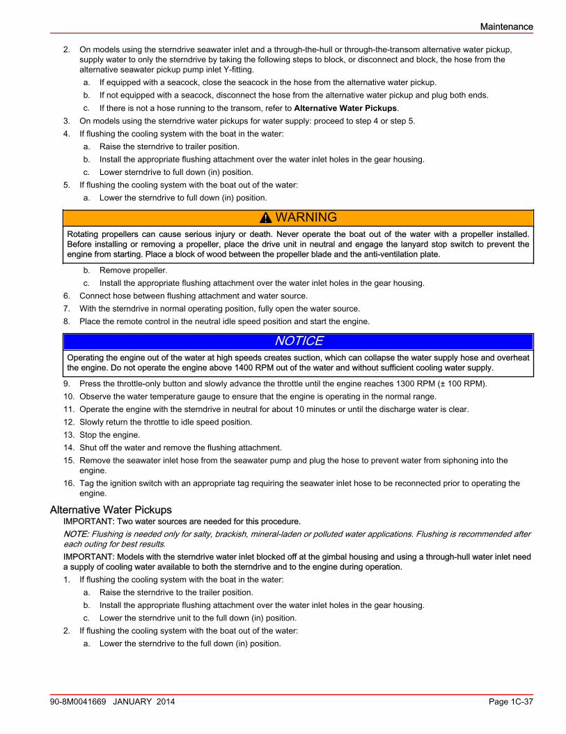
3. Connect a hose between the flushing attachment and a water source.4. Close the seacock, if equipped, to prevent water from siphoning into the engine or boat.5. Remove the seawater inlet hose from the seawater pump at the location shown. Plug the hose to prevent water from
siphoning into the engine or boat.
33208
Seawater inlet hose connection
6. Using a suitable adapter, connect the flushing hose from the water source to the water inlet of the seawater pump.
NOTICEWithout sufficient cooling water, the engine, the water pump, and other components will overheat and suffer damage. Providea sufficient supply of water to the water inlets during operation.
7. With the sterndrive in normal operating position, open the water source fully.8. Place the remote control in neutral idle speed position and start engine.
NOTICEOperating the engine out of the water at high speeds creates suction, which can collapse the water supply hose and overheatthe engine. Do not operate the engine above 1400 RPM out of the water and without sufficient cooling water supply.
9. Slowly advance the throttle until the engine reaches 1300 RPM (± 100 RPM).10. Observe the water temperature gauge to ensure that the engine is operating in the normal range.11. Operate the engine with the sterndrive in neutral for about 10 minutes or until discharge water is clear.12. Slowly return the throttle to the idle speed position.13. Stop the engine.14. Shut off the water and remove the flushing attachments.15. If the boat is out of the water, install the water inlet hose to the aft side of the seawater pump. Tighten the hose clamp
securely.16. If the boat is in the water, tag the ignition switch with an appropriate tag requiring the seawater inlet hose to be
reconnected prior to operating the engine.
SeaCore Power Package Flushing ProcedureNOTE: Flushing is needed only for salt, brackish, mineral‑laden or polluted water applications. Flushing is recommended aftereach outing for best results.
Maintenance
Page 1C-38 90-8M0041669 JANUARY 2014
IMPORTANT: Flushing the SeaCore power package with the boat and sterndrive in the water is less effective. Flushing theSeaCore power package is most effective when performed with the boat and sterndrive out of the water, such as on a boat liftor trailer.
Models Using the Sterndrive Water PickupIMPORTANT: The system is designed to flush the Bravo sterndrive and the engine with one water source. Do not block orremove the inlet water hose from the sterndrive to the engine.NOTE: Engines with the sterndrive water inlet blocked off at the gimbal housing: refer to Alternative Water Pickups.
! WARNINGRotating propellers can cause serious injury or death. Never operate the boat out of the water with a propeller installed.Before installing or removing a propeller, place the drive unit in neutral and engage the lanyard stop switch to prevent theengine from starting. Place a block of wood between the propeller blade and the anti‑ventilation plate.
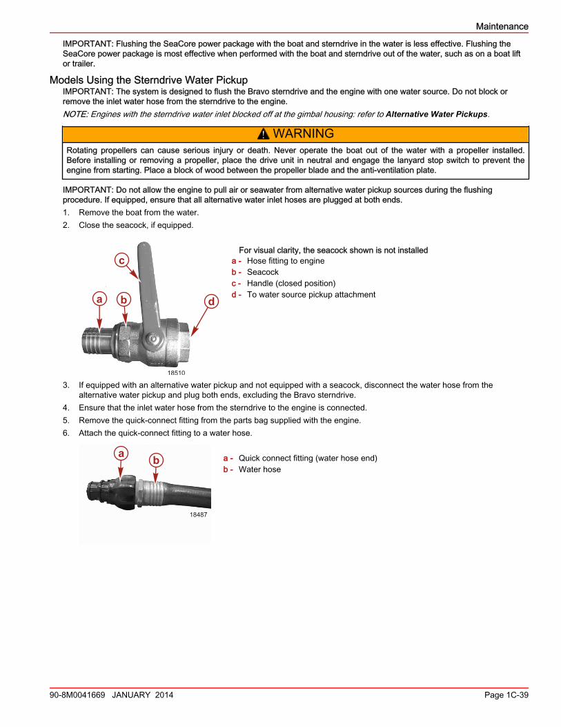
IMPORTANT: Do not allow the engine to pull air or seawater from alternative water pickup sources during the flushingprocedure. If equipped, ensure that all alternative water inlet hoses are plugged at both ends.1. Remove the boat from the water.2. Close the seacock, if equipped.
For visual clarity, the seacock shown is not installeda - Hose fitting to engineb - Seacockc - Handle (closed position)d - To water source pickup attachment
3. If equipped with an alternative water pickup and not equipped with a seacock, disconnect the water hose from thealternative water pickup and plug both ends, excluding the Bravo sterndrive.
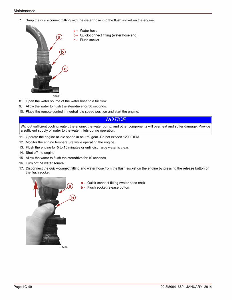
4. Ensure that the inlet water hose from the sterndrive to the engine is connected.5. Remove the quick‑connect fitting from the parts bag supplied with the engine.6. Attach the quick‑connect fitting to a water hose.
a - Quick connect fitting (water hose end)b - Water hose
a
c
b d
18510
18487
a b
Maintenance
90-8M0041669 JANUARY 2014 Page 1C-39
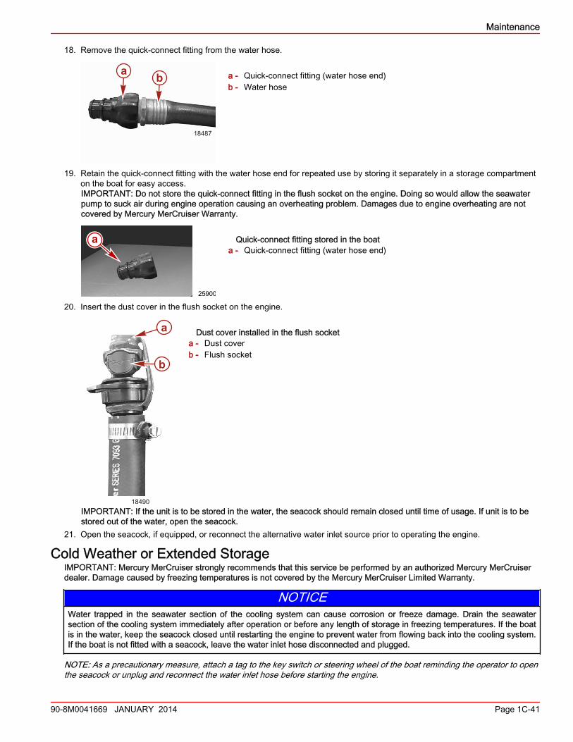
7. Snap the quick‑connect fitting with the water hose into the flush socket on the engine.
a - Water hoseb - Quick‑connect fitting (water hose end)c - Flush socket
8. Open the water source of the water hose to a full flow.9. Allow the water to flush the sterndrive for 30 seconds.10. Place the remote control in neutral idle speed position and start the engine.
NOTICEWithout sufficient cooling water, the engine, the water pump, and other components will overheat and suffer damage. Providea sufficient supply of water to the water inlets during operation.
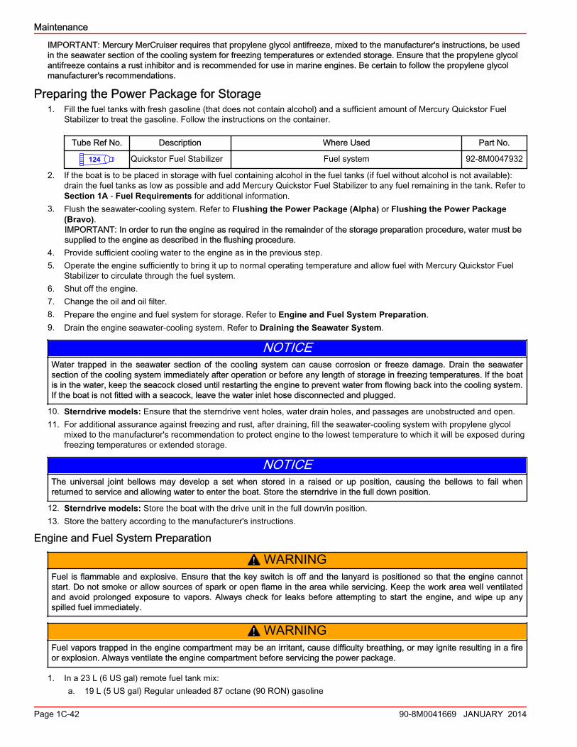
11. Operate the engine at idle speed in neutral gear. Do not exceed 1200 RPM.12. Monitor the engine temperature while operating the engine.13. Flush the engine for 5 to 10 minutes or until discharge water is clear.14. Shut off the engine.15. Allow the water to flush the sterndrive for 10 seconds.16. Turn off the water source.17. Disconnect the quick‑connect fitting and water hose from the flush socket on the engine by pressing the release button on
the flush socket.
a - Quick‑connect fitting (water hose end)b - Flush socket release button
a
b
c
18489
b
a
18488
Maintenance
Page 1C-40 90-8M0041669 JANUARY 2014
18. Remove the quick‑connect fitting from the water hose.
a - Quick‑connect fitting (water hose end)b - Water hose
19. Retain the quick‑connect fitting with the water hose end for repeated use by storing it separately in a storage compartmenton the boat for easy access.IMPORTANT: Do not store the quick‑connect fitting in the flush socket on the engine. Doing so would allow the seawaterpump to suck air during engine operation causing an overheating problem. Damages due to engine overheating are notcovered by Mercury MerCruiser Warranty.
Quick-connect fitting stored in the boata - Quick‑connect fitting (water hose end)
20. Insert the dust cover in the flush socket on the engine.
Dust cover installed in the flush socketa - Dust coverb - Flush socket
IMPORTANT: If the unit is to be stored in the water, the seacock should remain closed until time of usage. If unit is to bestored out of the water, open the seacock.
21. Open the seacock, if equipped, or reconnect the alternative water inlet source prior to operating the engine.
Cold Weather or Extended StorageIMPORTANT: Mercury MerCruiser strongly recommends that this service be performed by an authorized Mercury MerCruiserdealer. Damage caused by freezing temperatures is not covered by the Mercury MerCruiser Limited Warranty.
NOTICEWater trapped in the seawater section of the cooling system can cause corrosion or freeze damage. Drain the seawatersection of the cooling system immediately after operation or before any length of storage in freezing temperatures. If the boatis in the water, keep the seacock closed until restarting the engine to prevent water from flowing back into the cooling system.If the boat is not fitted with a seacock, leave the water inlet hose disconnected and plugged.
NOTE: As a precautionary measure, attach a tag to the key switch or steering wheel of the boat reminding the operator to openthe seacock or unplug and reconnect the water inlet hose before starting the engine.
18487
a b
25900
a
a
b
18490
Maintenance
90-8M0041669 JANUARY 2014 Page 1C-41
IMPORTANT: Mercury MerCruiser requires that propylene glycol antifreeze, mixed to the manufacturer's instructions, be usedin the seawater section of the cooling system for freezing temperatures or extended storage. Ensure that the propylene glycolantifreeze contains a rust inhibitor and is recommended for use in marine engines. Be certain to follow the propylene glycolmanufacturer's recommendations.
Preparing the Power Package for Storage1. Fill the fuel tanks with fresh gasoline (that does not contain alcohol) and a sufficient amount of Mercury Quickstor Fuel
Stabilizer to treat the gasoline. Follow the instructions on the container.
Tube Ref No. Description Where Used Part No.
124 Quickstor Fuel Stabilizer Fuel system 92-8M0047932
2. If the boat is to be placed in storage with fuel containing alcohol in the fuel tanks (if fuel without alcohol is not available):drain the fuel tanks as low as possible and add Mercury Quickstor Fuel Stabilizer to any fuel remaining in the tank. Refer toSection 1A ‑ Fuel Requirements for additional information.
3. Flush the seawater‑cooling system. Refer to Flushing the Power Package (Alpha) or Flushing the Power Package(Bravo).IMPORTANT: In order to run the engine as required in the remainder of the storage preparation procedure, water must besupplied to the engine as described in the flushing procedure.
4. Provide sufficient cooling water to the engine as in the previous step.5. Operate the engine sufficiently to bring it up to normal operating temperature and allow fuel with Mercury Quickstor Fuel
Stabilizer to circulate through the fuel system.6. Shut off the engine.7. Change the oil and oil filter.8. Prepare the engine and fuel system for storage. Refer to Engine and Fuel System Preparation.9. Drain the engine seawater‑cooling system. Refer to Draining the Seawater System.
NOTICEWater trapped in the seawater section of the cooling system can cause corrosion or freeze damage. Drain the seawatersection of the cooling system immediately after operation or before any length of storage in freezing temperatures. If the boatis in the water, keep the seacock closed until restarting the engine to prevent water from flowing back into the cooling system.If the boat is not fitted with a seacock, leave the water inlet hose disconnected and plugged.
10. Sterndrive models: Ensure that the sterndrive vent holes, water drain holes, and passages are unobstructed and open.11. For additional assurance against freezing and rust, after draining, fill the seawater‑cooling system with propylene glycol
mixed to the manufacturer's recommendation to protect engine to the lowest temperature to which it will be exposed duringfreezing temperatures or extended storage.
NOTICEThe universal joint bellows may develop a set when stored in a raised or up position, causing the bellows to fail whenreturned to service and allowing water to enter the boat. Store the sterndrive in the full down position.
12. Sterndrive models: Store the boat with the drive unit in the full down/in position.13. Store the battery according to the manufacturer's instructions.
Engine and Fuel System Preparation
! WARNINGFuel is flammable and explosive. Ensure that the key switch is off and the lanyard is positioned so that the engine cannotstart. Do not smoke or allow sources of spark or open flame in the area while servicing. Keep the work area well ventilatedand avoid prolonged exposure to vapors. Always check for leaks before attempting to start the engine, and wipe up anyspilled fuel immediately.
! WARNINGFuel vapors trapped in the engine compartment may be an irritant, cause difficulty breathing, or may ignite resulting in a fireor explosion. Always ventilate the engine compartment before servicing the power package.
1. In a 23 L (6 US gal) remote fuel tank mix:a. 19 L (5 US gal) Regular unleaded 87 octane (90 RON) gasoline
Maintenance
Page 1C-42 90-8M0041669 JANUARY 2014
b. 1.89 L (2 US qts) Premium Plus 2‑Cycle TC‑W3 Outboard Oilc. 150 mL (5.0 fl oz) Quickstor Fuel Stabilizer
Tube Ref No. Description Where Used Part No.
115Premium Plus 2-cycle TC-W3 Outboard Oil Fuel system 92-858026K01
Quickstor Fuel Stabilizer Fuel system Obtain Locally
2. Allow the engine to cool down.IMPORTANT: Immediately wipe up any fuel spills or sprays.
3. Close the fuel shut off valve, if equipped. Disconnect and plug the fuel inlet fitting if not equipped with a fuel shut off valve.4. Connect the remote fuel tank (with the fogging mixture) to the fuel inlet fitting.5. Supply sufficient cooling water to the engine. Refer to the appropriate Flushing the Power Package procedure.
NOTICERunning out of fuel can damage catalyst components. Do not allow the fuel tanks to become empty during operation.
6. Start and operate the engine at 1300 RPM for five minutes.7. After operating the engine for the specified time, slowly return the throttle to idle RPM and shut the engine off.
IMPORTANT: Ensure that some fogging mixture remains in the engine. Do not allow the engine's fuel system to becomecompletely dry.
8. Replace the water separating fuel filter element. Refer to Section 5 for the proper procedure.
Power Package Recommissioning1. Ensure that all cooling system hoses are connected properly and hose clamps are tight.
! CAUTIONDisconnecting or connecting the battery cables in the incorrect order can cause injury from electrical shock or can damagethe electrical system. Always disconnect the negative (‑) battery cable first and connect it last.
2. Install a fully charged battery. Clean the battery cable clamps and terminals and reconnect the cables. Tighten each cableclamp securely.
3. Coat the terminal connections with a battery terminal sealant.
Tube Ref No. Description Where Used Part No.
Battery Terminal Sealant Battery terminal connections Obtain Locally
4. Perform the following prior to starting the engine:a. Install the bilge drain plug.b. Open the engine hatch.c. Turn the battery switch on.d. Operate the bilge blowers.e. Open the fuel shut‑off valve.f. Open the seacock, if equipped.g. Close the drain system.h. Check the engine oil.i. Listen for the audio warning alarm to sound when the ignition switch is moved to the "ON" position.
NOTICEWithout sufficient cooling water, the engine, the water pump, and other components will overheat and suffer damage. Providea sufficient supply of water to the water inlets during operation.
5. Start the engine and closely observe the instrumentation to ensure that all systems are functioning correctly.6. Carefully inspect the engine for fuel, oil, fluid, water, and exhaust leaks.7. Inspect the steering system, shift, and throttle control for proper operation.
Maintenance
90-8M0041669 JANUARY 2014 Page 1C-43

Maintenance
Notes:
Page 1C-44 90-8M0041669 JANUARY 2014