Embed Size (px)
Citation preview
Construction and Building Materials 71 (2014) 334–343
Contents lists available at ScienceDirect
Construction and Building Materials
journal homepage: www.elsevier .com/locate /conbui ldmat
Improved chloride resistance of high-strength concrete amended withcoal bottom ash for internal curing
http://dx.doi.org/10.1016/j.conbuildmat.2014.08.0690950-0618/� 2014 Elsevier Ltd. All rights reserved.
⇑ Corresponding author. Tel.: +82 42 350 3623; fax: +82 350 3610.E-mail address: [email protected] (H.K. Lee).
H.K. Kim a, J.G. Jang b, Y.C. Choi c, H.K. Lee b,⇑a School of Architecture, Chosun University, 309 Pilmun-daero, Dong-gu, Gwangju 501-759, South Koreab Department of Civil and Environmental Engineering, Korea Advanced Institute of Science and Technology, Guseong-dong, Yuseong-gu, Daejeon 305-701, South Koreac Korea Conformity Laboratories, 1465-4 Seocho-3-dong, Seocho-gu, Seoul, South Korea
h i g h l i g h t s
� Chloride resistance of high-strength concrete was improved by using coal bottom ash aggregates.� Chloride did not readily diffuse to the cement paste in the vicinity of bottom ash.� Bound chloride per total chloride in the mortar was decreased when bottom ash was applied.
a r t i c l e i n f o
Article history:Received 24 January 2014Received in revised form 21 August 2014Accepted 24 August 2014
Keywords:Coal bottom ashInternal curingChloride diffusionChloride bindingElectron probe microanalyzer
a b s t r a c t
The present work studies a chloride resistance of high-strength concrete incorporating bottom ashaggregates for internal curing. The chloride diffusion in concrete was evaluated by measuring the diffu-sion distance through steady-state and rapid-state penetration tests. The acid-soluble and water-solublechloride contents in concrete were measured to evaluate the total and bound chloride concentrations inconcrete. To detect the crystalline phase of hydration products that can bind chloride, a thermal analysisand an X-ray diffraction (XRD) analysis were carried out. In addition, the path of chloride penetration inconcrete was analyzed by using an electron probe microanalyzer (EPMA). The results showed that,although there was no significant effect on the diffusion length, bottom ash in high-strength concretecan significantly reduce the amount of chloride diffusion.
� 2014 Elsevier Ltd. All rights reserved.
1. Introduction
Internal curing using lightweight aggregate is a promisingtechnique to mitigate the autogenous shrinkage of high-strengthconcrete [1]. Water absorbed in lightweight aggregates can offsetthe water loss in cement paste by hydration of cementitious mate-rials (i.e., self-desiccation), thereby counteracting the shrinkagecaused by self-desiccation [1]. A comprehensive introduction tothe subject of internal curing can be found in a report by the RILEMTechnical Committee TC 196-ICC [2]. Note that, for the high-strength concrete with lightweight aggregate, the high cementcontent was required to balance the degradation of mechanicalproperties and durability induced by the lightweight aggregates.As a result, the autogenous shrinkage could be a relevant problemin high-strength concrete with lightweight aggregate.
As internal curing is a very important factor that may preventthe cracking of concrete structures at early age, extensive studieson concrete incorporating internal curing materials have been car-ried out [3]. In particular, resistance to chloride penetration is animportant research topic [3,4], given that high-strength concreteapplied in marine construction, such as bridge decks and piers, off-shore platforms, and floating structures, where there is a high riskof steel corrosion in reinforcement concrete induced by chloride[3,5–9].
In the case of concrete containing lightweight aggregates, themoisture in concrete can be transferred via porous networks inlightweight aggregates, and consequently the water permeabilityis higher compared with that in normal aggregate concrete[3,10,11]. However, although the chloride diffusivity of concreteis generally increased with increased porosity and permeabilityof concrete, experimental results have shown that the chloride dif-fusivities of high-strength concrete with lightweight aggregatewere similar or, in some cases, lower compared to that of normalaggregate concrete [3,11]. This was posited to be due to the dense
H.K. Kim et al. / Construction and Building Materials 71 (2014) 334–343 335
interfacial transition zone (ITZ) between the lightweight aggre-gates and cement paste, which would hinder the penetration ofchloride ions [3,4,12].
In previous studies by the present authors [13,14], coal bottomash, a byproduct from coal thermal power plants, was utilized asan alternative internal curing material. The shrinkage characteris-tics, hydration kinetics, and mechanical properties of concrete withbottom ash were investigated [13,14]. The experimental resultsshowed that the introduction of bottom ash decreased the autoge-nous shrinkage of concrete, and increased the degree of hydrationand compressive strength [13,14]. The autogenous shrinkage of theconcrete with W/C of 0.3 was decreased or eliminated when50 vol.% of natural fine aggregates was replaced with bottom ashwith particle size of 2–5 mm [13]. Moreover, water absorbed inthe pre-wetted bottom ash led the hydration enhancement ofcement matrix during the curing of the concrete (i.e. internal cur-ing), so that the compressive strength of the concrete with bottomash at 91 days of curing was almost equivalent with that of theconcrete with normal aggregates [13,14]. However, the chlorideresistance of concrete with bottom ash might be different fromthat of concrete with artificial lightweight aggregates, a conven-tional material for internal curing, due to the following reasons.
Above all, the pozzolanic reactivity of bottom ash could be oneof the factors hindering the diffusion of chloride. Pozzolanic reac-tion in concrete with bottom ash might increase the concentrationof ions, such as Al(OH)4
�, H3SiO4�, and H2SiO4
2�, and this coulddisturb chloride diffusion (c.f. [15,16]). Moreover, the content ofalumina (Al2O3) in bottom ash and its reactivity were found tobe higher than those in artificial lightweight aggregates [13,14].It was predicted that the chloride penetrated in concrete with bot-tom ash could be bound in the form of Friedel’s salts (Ca3Al2O6�CaCl2�10H2O), as the formation of Friedel’s salts can be promotedin concrete with high alumina content [17–19]. However, thedegree of hydration in the cement matrix of concrete with bottomash was lower than that of artificial lightweight aggregates [14],which may adversely affect the resistance to chloride ion penetra-tion in concrete.
The present study conducted an experimental evaluation of thediffusion and binding of chloride in high-strength concreteincorporating bottom ash aggregates for internal curing. Theexperimental results of concrete with bottom ash were comparedwith those of concrete with artificial lightweight aggregates. Theporosity and capillary water absorption characteristics of concrete,which may influence chloride diffusion, were measured. The chlo-ride diffusion in concrete was evaluated by measuring the diffusiondistance through stead-state and rapid-state penetration tests. Theacid-soluble and water-soluble chloride contents in concrete weremeasured to evaluate the total and bound chloride concentrationin concrete. To detect the crystalline phase of hydration productsthat can bind chloride, a thermal analysis and an X-ray diffraction(XRD) analysis were carried out. In addition, the path of chloridepenetration in concrete was analyzed by using an electron probemicroanalyzer (EPMA).
2. Materials and mix proportion
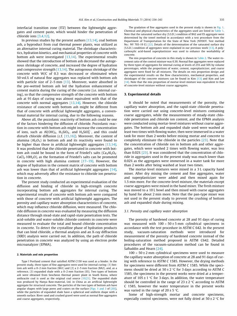
Type I Portland cement that satisfied ASTM C150 was used as a binder. In thepresent study, three types of fine aggregates were used for internal curing: (1) bot-tom ash with a 0–2 mm fraction (BA1) and (2) a 2–5 mm fraction (BA2), and, as areference, (3) expanded shale with a 0–2 mm fraction (ES). Two types of bottomash were obtained from Seocheon thermal power plant in South Korea, whereanthracite coal is used as the original coal source [10,21]. The expanded shalewas produced by Hanya Raw-material, Ltd. in China as an artificial lightweightaggregate for structural concrete. The particles of the two types of bottom ash haveangular shapes with large pores and craters on the surface (Figs. 1 and 3 of [20]),while the particles of expanded shale have a spherical and uniform shape with asmooth surface. River sand and crushed gravel were used as normal fine aggregatesand coarse aggregates, respectively.
The gradation of fine aggregates used in the present study is shown in Fig. 1.Chemical and physical characteristics of the aggregates used are listed in Table 1.Note that the saturated surface dry (S.S.D.) condition of BA2 and ES aggregate weredetermined by the towel method in accordance with a test procedure from theDepartment of Transportation for the State of New York (NYDOT. Test methodNo.: NY 703-19 E) [22]. Details of the determination of the saturated surface dry(S.S.D.) condition of aggregates were explained in our previous work [13]. A poly-carboxylic acid-based superplastisizer was used to enhance the workability ofconcrete.
The mix proportion of concrete in this study is shown in Table 2. The water-to-cement ratio of the control mixture was 0.30. Normal fine aggregates were replacedby three types of aggregates for internal curing at levels of 25% and 50% by volumepercentages, while the proportions of water, cement, superplasticizer, and coarseaggregates were fixed for all mixtures. The details on mix proportion design andthe experimental results on the flow characteristics, mechanical properties, andshrinkages of the concrete mixtures can be found in Kim [13] and Kim and Lee[14]. Note that the mix proportion of mortar-level mixture was equivalent to thatof concrete-level mixture without coarse aggregates.
3. Experimental details
It should be noted that measurements of the porosity, thecapillary water absorption, and the rapid-state chloride penetra-tion were carried out using concrete-level mixtures containingcoarse aggregates, while the measurements of steady-state chlo-ride penetration and chloride ion content, and the EPMA analysiswere conducted using mortar-level mixtures without coarse aggre-gates. The bottom ash and expanded shale used were washed atleast two times with flowing water, then were immersed in a watertank for more than 2 weeks before mixing mortar and concrete tocompletely eliminate the chloride in the particles [23]. Note thatthe concentration of chloride ion in bottom ash and other aggre-gates, which were washed 2 times with flowing water, was lessthan 0.02% [23]. It was considered that the concentration of chlo-ride in aggregates used in the present study was much lower than0.02% as the aggregates were immersed in a water tank for morethan 2 weeks after being washed at least two times.
The mortar-level mixtures were mixed in a 3 L capacity handmixer. After dry mixing the cement and fine aggregates, waterand superplasticizer were added and then mixed again for1.5 min more. For the concrete-level mixture, the materials exceptcoarse aggregates were mixed in the hand mixer. The fresh mixturewas moved to a 10 L bowl and then mixed with coarse aggregatesby hand for about 2 min more. Note that the pan-type mixer wasnot used in the present study to prevent the crushing of bottomash and expanded shale during mixing.
3.1. Porosity and capillary water absorption
The porosity of hardened concrete at 28 and 91 days of curingwas measured with 100 � 50 ± 5 mm cylindrical specimens inaccordance with the test procedure in ASTM C 642. In the presentstudy, vacuum-saturation methods were introduced formeasurement of the porosity of hardened concrete instead of theboiling-saturation method proposed in ASTM C642. Detailedprocedures of the vacuum-saturation method can be found inSafiuddin and Hearn [24].
100 � 50 ± 2 mm cylindrical specimens were used to measurethe capillary water absorption of concrete at 28 and 91 days of cur-ing with reference to ASTM C 1585. However, the drying methodsfor specimens were different from ASTM C 1585. While the speci-mens should be dried at 50 ± 2 �C for 3 days according to ASTM C1585, the specimens in the present works were dried at a temper-ature of 105 ± 1 �C for 3 days. In addition, the water temperatureshould be controlled in the range of 23 ± 2 �C according to ASTMC 1585, however the water temperature in the present workswas varied in the range of 20 ± 5 �C.
Some of high-strength mortar and concrete specimens,especially control specimens, were not fully dried at 50 ± 2 �C for
0
20
40
60
80
100
0.1 1 10
Cum
ulat
ive
pass
ing
[w.t
%]
Sieve size [mm]
BA1 100%
BA2 100%
ES 100%
NS 100%
BA1 50% + NS 50%
BA2 50% + NS 50%
ES 50% + NS 50%
Standard (ASTM C33)
Fig. 1. Gradation curves of aggregates.
(a)
(b)
0 25 50
BA1
BA2
ES
91st day
7
9
11
13
15
0 25 50
Por
osit
y [v
ol.%
]
28th day
Replacement ratio of aggregates [vol.%]
0 25 50
BA1
BA2
ES
91st day
0.3
0.5
0.7
0.9
0 25 50
Cap
illar
y w
ater
abs
orpt
ion
[k
g/(m
2 ·h1/
2 )]
28th day
Replacement ratio of aggregates [vol.%]
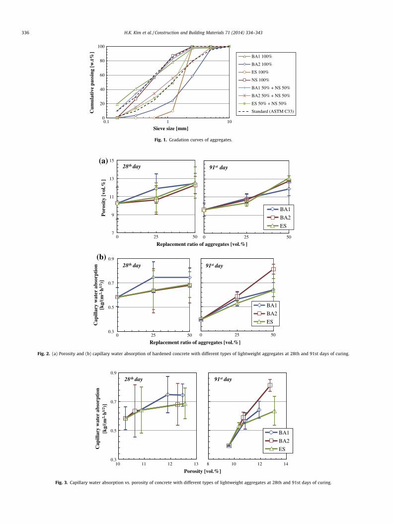
Fig. 2. (a) Porosity and (b) capillary water absorption of hardened concrete with different types of lightweight aggregates at 28th and 91st days of curing.
8 10 12 14
BA1
BA2
ES
91st day
0.3
0.5
0.7
0.9
10 11 12 13
Cap
illar
y w
ater
abs
orpt
ion
[k
g/(m
2 ·h1/
2 )]
28th day
Porosity [vol.%]
Fig. 3. Capillary water absorption vs. porosity of concrete with different types of lightweight aggregates at 28th and 91st days of curing.
336 H.K. Kim et al. / Construction and Building Materials 71 (2014) 334–343
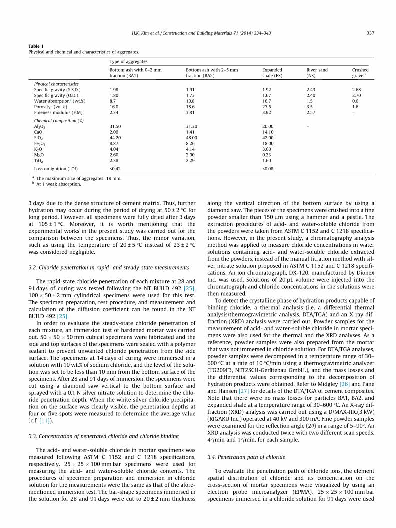
Table 1Physical and chemical and characteristics of aggregates.
Type of aggregates
Bottom ash with 0–2 mmfraction (BA1)
Bottom ash with 2–5 mmfraction (BA2)
Expandedshale (ES)
River sand(NS)
Crushedgravela
Physical characteristicsSpecific gravity (S.S.D.) 1.98 1.91 1.92 2.43 2.68Specific gravity (O.D.) 1.80 1.73 1.67 2.40 2.70Water absorptionb (wt.%) 8.7 10.8 16.7 1.5 0.6Porosityb (vol.%) 16.0 18.6 27.5 3.5 1.6Fineness modulus (F.M) 2.34 3.81 3.92 2.57 –
Chemical composition (%)Al2O3 31.50 31.30 20.00 –CaO 2.00 1.41 14.10SiO2 44.20 48.00 42.00Fe2O3 8.87 8.26 18.00K2O 4.04 4.14 3.60MgO 2.60 2.00 0.23TiO2 2.38 2.29 1.60
Loss on ignition (LOI) <0.42 <0.08
a The maximum size of aggregates: 19 mm.b At 1 weak absorption.
H.K. Kim et al. / Construction and Building Materials 71 (2014) 334–343 337
3 days due to the dense structure of cement matrix. Thus, furtherhydration may occur during the period of drying at 50 ± 2 �C forlong period. However, all specimens were fully dried after 3 daysat 105 ± 1 �C. Moreover, it is worth mentioning that theexperimental works in the present study was carried out for thecomparison between the specimens. Thus, the minor variation,such as using the temperature of 20 ± 5 �C instead of 23 ± 2 �Cwas considered negligible.
3.2. Chloride penetration in rapid- and steady-state measurements
The rapid-state chloride penetration of each mixture at 28 and91 days of curing was tested following the NT BUILD 492 [25].100 � 50 ± 2 mm cylindrical specimens were used for this test.The specimen preparation, test procedure, and measurement andcalculation of the diffusion coefficient can be found in the NTBUILD 492 [25].
In order to evaluate the steady-state chloride penetration ofeach mixture, an immersion test of hardened mortar was carriedout. 50 � 50 � 50 mm cubical specimens were fabricated and theside and top surfaces of the specimens were sealed with a polymersealant to prevent unwanted chloride penetration from the sidesurface. The specimens at 14 days of curing were immersed in asolution with 10 wt.% of sodium chloride, and the level of the solu-tion was set to be less than 10 mm from the bottom surface of thespecimens. After 28 and 91 days of immersion, the specimens werecut using a diamond saw vertical to the bottom surface andsprayed with a 0.1 N silver nitrate solution to determine the chlo-ride penetration depth. When the white silver chloride precipita-tion on the surface was clearly visible, the penetration depths atfour or five spots were measured to determine the average value(c.f. [11]).
3.3. Concentration of penetrated chloride and chloride binding
The acid- and water-soluble chloride in mortar specimens wasmeasured following ASTM C 1152 and C 1218 specifications,respectively. 25 � 25 � 100 mm bar specimens were used formeasuring the acid- and water-soluble chloride contents. Theprocedures of specimen preparation and immersion in chloridesolution for the measurements were the same as that of the afore-mentioned immersion test. The bar-shape specimens immersed inthe solution for 28 and 91 days were cut to 20 ± 2 mm thickness
along the vertical direction of the bottom surface by using adiamond saw. The pieces of the specimens were crushed into a finepowder smaller than 150 lm using a hammer and a pestle. Theextraction procedures of acid- and water-soluble chloride fromthe powders were taken from ASTM C 1152 and C 1218 specifica-tions. However, in the present study, a chromatography analysismethod was applied to measure chloride concentrations in watersolutions containing acid- and water-soluble chloride extractedfrom the powders, instead of the manual titration method with sil-ver nitrate solution proposed in ASTM C 1152 and C 1218 specifi-cations. An ion chromatograph, DX-120, manufactured by DionexInc. was used. Solutions of 20 lL volume were injected into thechromatograph and chloride concentrations in the solutions werethen measured.
To detect the crystalline phase of hydration products capable ofbinding chloride, a thermal analysis (i.e. a differential thermalanalysis/thermogravimetric analysis, DTA/TGA) and an X-ray dif-fraction (XRD) analysis were carried out. Powder samples for themeasurement of acid- and water-soluble chloride in mortar speci-mens were also used for the thermal and the XRD analyses. As areference, powder samples were also prepared from the mortarthat was not immersed in chloride solution. For DTA/TGA analyses,powder samples were decomposed in a temperature range of 30–600 �C at a rate of 10 �C/min using a thermogravimetric analyzer(TG209F3, NETZSCH-Gerätebau GmbH.), and the mass losses andthe differential values corresponding to the decomposition ofhydration products were obtained. Refer to Midgley [26] and Paneand Hansen [27] for details of the DTA/TGA of cement composites.Note that there were no mass losses for particles BA1, BA2, andexpanded shale at a temperature range of 30–600 �C. An X-ray dif-fraction (XRD) analysis was carried out using a D/MAX-IIIC(3 kW)(RIGAKU Inc.) operated at 40 kV and 300 mA. Fine powder sampleswere examined for the reflection angle (2h) in a range of 5–90�. AnXRD analysis was conducted twice with two different scan speeds,4�/min and 1�/min, for each sample.
3.4. Penetration path of chloride
To evaluate the penetration path of chloride ions, the elementspatial distribution of chloride and its concentration on thecross-section of mortar specimens were visualized by using anelectron probe microanalyzer (EPMA). 25 � 25 � 100 mm barspecimens immersed in a chloride solution for 91 days were used
Table 2Mix proportion.
Specimen Unit weight (kg/m3)
Water Cement Fine aggregate Coarse aggregates
NS BA1 BA2 ES
Control 170 566 720 0 0 0 926BA1-25 540 145 0 0BA1-50 360 290 0 0BA2-25 540 0 140 0BA2-50 360 0 280 0ES-25 540 0 0 141ES-50 360 0 0 282
338 H.K. Kim et al. / Construction and Building Materials 71 (2014) 334–343
for the EPMA analysis. The specimens were cut into slices with4 ± 1 mm thickness along the vertical direction of the bottom sur-face by using a diamond saw and were polished with 600-grit fol-lowed by polishing with 1000-, 1500-, and 4000-grit sandpapers.After each polishing, the specimens were cleaned by compressedair and then coated with carbon to provide a conductive surfacefor viewing the EPMA images. The EPMA analysis was carried outusing a LEO 1455VP environment scanning electron microscope,manufactured by Carl Zeiss Inc., Germany. Backscattered electron(BSE) images of the cross-sections of the mortar specimens werealso taken by using the EPMA to identify the materials composingthe mortar specimens.
4. Results and discussion
4.1. Porosity and capillary water absorption
The experimental data of porosity and capillary water absorp-tion of hardened mixtures are plotted in Fig. 2. Note that the errorbars in the figure the regular standard deviations of the experimen-tal results. The porosity and capillary water absorption of concreteare strongly related with the chloride penetration in the concretematrix [11]. Chia and Zhang (2002) reported that the chloride pen-etration in concrete was mechanically affected by porosity in theconcrete and the connectivity of pores [11]. Even if the porosityof concrete is high, chloride penetration may be low when the con-nectivity of pores is low (see the schematic illustration given inFig. 2 of Chia and Zhang [11]. In the present study, the connectivityof the pore system in concrete was assessed in terms of the capil-lary water absorption.
As shown in Fig. 2, both the porosity and the capillary waterabsorption of concrete seemed to be increased with an increase
4
6
8
10
12
0 25 50
Dif
fusi
on c
oeff
icie
nt [
10-1
2m
2 /s]
28th day
Replacement ratio
Fig. 4. Chloride diffusion coefficients measured by rapid-state test vs. replacement ratio oof curing.
of the replacement ratio of lightweight aggregates, regardless ofthe types of aggregates. However, especially for the specimens at28 days of curing, the increased values were within the range ofthe high dispersion error bars. Moreover, it can be said that therelationship between the porosity in the concrete and the connec-tivity was merely affected by types of aggregates. As shown inFig. 3, while the concrete with BA2 has slightly higher values ofcapillary water absorption than that with ES at 91 days of curing,this phenomenon was only clearly observed when the porositywas higher than 12%. Therefore, these results denoted that the poresystem in the concrete with bottom ash was seldom affected by thepozzolanic reaction of bottom ash.
4.2. Chloride penetration in rapid- and steady-state measurements
Fig. 4 shows the chloride diffusion coefficient of concrete mea-sured by a rapid-state test [25] against the replacement ratio oflightweight aggregates. Note that the diffusion coefficients of con-crete in the NT Build 492 specifications were calculated based onthe penetration depth of chloride in concrete [25]. As shown inFig. 4, although the diffusion coefficients of the concrete with bot-tom ash seemed to be slightly lower than those of the concretewith expanded shale, the gap was in the range of the dispersionerror bars.
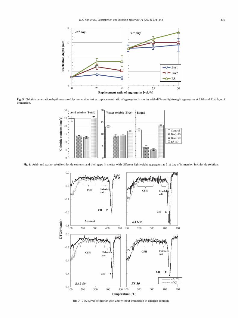
Fig. 5 shows the chloride ion penetration depth of mortar withdifferent lightweight aggregates measured by an immersion test(steady-state test) against the replacement ratio of aggregates.Notice that the penetration depth measured by the steady-statetest indicate cumulative penetration of chloride during theimmersion; meanwhile, the diffusion coefficient measured by therapid-state test indicate the chloride penetration resistance of con-crete at a certain age. As shown in Fig. 5, although the penetrationdepth of mortar with bottom ash was slightly lower than that withexpanded shale, the gap between them was not significant consid-ering the range of error bar. These results indicated that there wasno significant effect of the bottom ash aggregates on the diffusionvelocity of chloride ion in terms of diffusion length.
4.3. Concentration of penetrated chloride and chloride binding
Fig. 6 shows the acid- and water-soluble chloride contents inmortar with different types of lightweight aggregates at the 91stday of immersion. Note that, in general, the values of acid- andwater-soluble chloride contents indicate the concentration of totaland free chloride in specimens; and the gap between the two
0 25 50
BA1BA2ES
91st day
of aggregates [vol.%]
f aggregates in concrete with different lightweight aggregates at 28th and 91st days
0 25 50
BA1
BA2
ES
91st day
4
6
8
10
12
0 25 50
Pen
etra
tion
dep
th [
mm
]
28th day
Replacement ratio of aggregates [vol.%]
Fig. 5. Chloride penetration depth measured by immersion test vs. replacement ratio of aggregates in mortar with different lightweight aggregates at 28th and 91st days ofimmersion.
ControlBA1-50BA2-50ES-50
Bound
0
5
10
15
20Water soluble (Free)
0
5
10
15
20
25
30
Chl
orid
e co
nten
ts [
mg/
g]
Acid soluble (Total)
Fig. 6. Acid- and water- soluble chloride contents and their gaps in mortar with different lightweight aggregates at 91st day of immersion in chloride solution.
100 200 300 400 500
BA1-50
Friedel'ssalt
CH
CSH
-0.8
-0.6
-0.4
-0.2
0.0
100 200 300 400 500
Control
Friedel'ssalt
CH
CSH
100 200 300 400 500
w/o Clw/ ClES-50
Friedel'ssalt
CH
CSH
-0.8
-0.6
-0.4
-0.2
0.0
100 200 300 400 500
BA2-50
Friedel'ssalt
CH
CSH
Temperature ( C)
DT
G/(
%/m
in)
Fig. 7. DTA curves of mortar with and without immersion in chloride solution.
H.K. Kim et al. / Construction and Building Materials 71 (2014) 334–343 339
10 11 12
Control
BA1-50
ES-50
BA2-50
w/ Cl
Fri
edel
'ssa
lts
300
400
500
600
700
800
10 11 12
Inte
nsit
y [C
PS]
ControlBA1-50BA2-50ES-50
w/o Cl
2 (deg)
Fig. 8. XRD patterns of Fridel’s salts in four types of mortar with and withoutimmersion in chloride solution.
1.00
1.10
1.20
1.30
1.40
Control BA1-50 BA2-50 ES-50
Mas
s lo
ss b
etw
een
180
C a
nd 3
00C
[wt.
%]
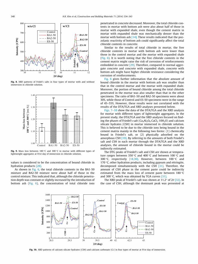
Fig. 9. Mass loss between 180 �C and 300 �C in mortar with different types oflightweight aggregates at 91st day of immersion in chloride solution.
340 H.K. Kim et al. / Construction and Building Materials 71 (2014) 334–343
values is considered to be the concentration of bound chloride inhydration products [28].
As shown in Fig. 6, the total chloride contents in the BA1-50mixture and BA2-50 mixture were about half of those in thecontrol mixture. This indicated that, although the chloride penetra-tion depth was constant or slightly increased by the introduction ofbottom ash (Fig. 6), the concentration of total chloride ions
39 39.5
Co
B
BA2-50
Cc
0
200
400
600
800
1000
1200
1400
1600
28.5 29.5
Inte
nsit
y [C
PS]
BA2-50
BA1-50 ES-50
Control
Cc
CSH
2 (de
Fig. 10. XRD patterns of calcium silicate hydrates (CSH) and calcium
penetrated in concrete decreased. Moreover, the total chloride con-tents in mortar with bottom ash were also about half of those inmortar with expanded shale, even though the cement matrix inmortar with expanded shale was mechanically denser than themortar with bottom ash [14]. These results indicated that the poz-zolanic reactivity of bottom ash could significantly affect the totalchloride contents in concrete.
Similar to the results of total chloride in mortar, the freechloride contents in mortar with bottom ash were lower thanthose in the control mortar and the mortar with expanded shale(Fig. 6). It is worth noting that the free chloride contents in thecement matrix might raise the risk of corrosion of reinforcementsembedded in concrete [29]. Therefore, compared to normal aggre-gate concrete and concrete with expanded shale, concrete withbottom ash might have higher chloride resistance considering thecorrosion of reinforcements.
Fig. 6 gives further information that the absolute amount ofbound chloride in the mortar with bottom ash was smaller thanthat in the control mortar and the mortar with expanded shale.Moreover, the portion of bound chloride among the total chloridepenetrated in the mortar was also smaller than that in the otherspecimens. The ratio of BA1-50 and BA2-50 specimens were about30%, while those of Control and ES-50 specimens were in the rangeof 45–55%. However, these results were not correlated with theresults of the DTA/TGA and XRD analyses presented below.
Figs. 7–10 show the data of the DTA/TGA and the XRD analysisfor mortar with different types of lightweight aggregates. In thepresent study, the DTA/TGA and the XRD analyses focused on find-ing the phases of Friedel’s salt (Ca3Al2O6�CaCl2�10H2O) and calciumsilicate hydrates (CSH) in mortar immersed in chloride solution.This is believed to be due to the chloride ions being bound in thecement matrix mainly in the following two forms: (1) chemicallybound in Friedel’s salt, or (2) physically adsorbed on theamorphous CSH [19]. By referring to the amounts of both Friedel’ssalt and CSH in each mortar through the DTA/TGA and the XRDanalyses, the amount of chloride bound in the mortar could beindirectly estimated.
The DTG peaks of Friedel’s salt and CSH are shown at tempera-ture ranges between 350 �C and 400 �C and between 100 �C and300 �C, respectively [18,30]. However, between 100 �C and170 �C, other hydration products, including gypsum and ettringite,decomposed simultaneously with the CSH [31]. Therefore, theamount of CSH phase in the cement paste could be indirectlyestimated from the mass loss of cement paste between 180 �Cand 300 �C, which was obtained by TGA curves [31].
The XRD peak of Friedel’s salt was shown at 11.2� of 2h [32]. Inthe case of CSH, although the dominant peak was presented at
42 42.5 43
ControlBA1-50BA2-50ES-50
ES-50Control
BA1-50
BA2-50
Cc
40
ntrol
ES-50
A1-50
g)
carbonate (Cc) in four types of mortar at 91st day of immersion.
H.K. Kim et al. / Construction and Building Materials 71 (2014) 334–343 341
29.2�, this was not clearly observed in this study and only hump-shaped peaks between 25� and 35� of 2h could be shown due toits amorphous phase [33]. The maximum intensity of these peaksis between 28� and 30� of 2h [33]. However, an XRD peak of the cal-cite (Cc) phase is also detected at this range (2h = 29.4) [34]. Forthis reason, XRD peaks of Cc at other diffraction angles, including39.4� and 42.4� [34], were evaluated along with the peaks between28� and 30� as additional peaks to better distinguish the Cc phase.
As shown in Fig. 7, the amount of Friedel’s salt in mortar couldnot be evaluated from the DTA curves of mortar. This was due tothe insignificant amount compared to other hydration products,
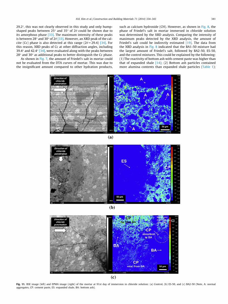
Fig. 11. BSE image (left) and EPMA image (right) of the mortar at 91st day of immeraggregates, CP: cement paste, ES: expanded shale, BA: bottom ash).
such as calcium hydroxide (CH). However, as shown in Fig. 8, thephase of Friedel’s salt in mortar immersed in chloride solutionwas determined by the XRD analysis. Comparing the intensity ofmaximum peaks detected by the XRD analysis, the amount ofFriedel’s salt could be indirectly estimated [19]. The data fromthe XRD analysis in Fig. 8 indicated that the BA1-50 mixture hadthe largest amount of Friedel’s salt, followed by BA2-50, ES-50,and the control mixtures. This could be explained by the following:(1) The reactivity of bottom ash with cement paste was higher thanthat of expanded shale [14]; (2) Bottom ash particles containedmore alumina contents than expanded shale particles (Table 1);
sion in chloride solution: (a) Control, (b) ES-50, and (c) BA2-50 (Note, A: normal
342 H.K. Kim et al. / Construction and Building Materials 71 (2014) 334–343
and (3) The interface area of bottom ash, especially BA1, was largerthan that of expanded shale [14]. From these reasons, a largeamount of monosulfate (AFm, Ca3Al2O6�CaSO4�12H2O), the initialcrystalline phase forming the Friedel’s salt, might develop at theinterface of bottom ash in mortar.
In the case of the CSH, the amount in mortar could be evaluatedfrom both DTA/TGA and XRD analyses. As shown in Fig. 9, BA1-50mixture has the largest value of mass loss at a temperature rangeof 180 �C to 300 �C, followed by BA2-50 and ES-50 mixtures, andthe control mixtures. Moreover, as shown in Fig. 9, the sums ofthe intensities of CSH and of Cc for the BA1-50 and BA2-50 mix-tures were higher than those for the control mixture and similarto those for the ES-50 mixture; meanwhile, the intensities of onlyCc for the BA1-50 and BA2-50 mixtures were lower than those ofthe control and ES-50 mixtures. These results indicate that theamount of CSH in the mortar with bottom ash was larger than thatin the control mortar and similar to that in the mortar withexpanded shale. This was clearly due to the high pozzolanicreactivity of bottom ash.
From the results of the DTA/TGA and the XRD analyses, it couldbe inferred that the amounts of chloride bound in mortar with bot-tom ash were higher than or similar to those in the control mortarand the mortar with expanded shale; these results are in conflictwith the data in Fig. 6.
The conflicting results indicated that some amount of chloridein both the control mortar and mortar with expanded shale maybe bound in certain forms different from the Friedel’s salt or CSH.In the present study, the authors attempted to detect candidatecrystalline phases, which were reported to possibly bind chloridechemically (e.g., the Kuzel’s salt (3CaO�Al2O3�1/2CaCl2�1/2CaCl2
�10H2O) and the iron-containing analog of Friedel’s salt(3CaO�(Al,Fe)2O3�CaCl2�10H2O) [34,35,36], by using a XRD analysis.However, these crystalline phases could not be detected due totheir insignificant amounts. Moreover, other hydration products(aside from CSH) that can bind chloride physically have not beenreported. Therefore, to understand these phenomena more clearly,further investigations should be carried out.
4.4. Penetration path of chloride
Fig. 11 shows the BSE images and EPMA images of the mortarimmersed in chloride solution for 91 days. Note that the EPMAimages in Fig. 11 present the spatial distribution of chloride andits concentration.
Fig. 11(a) and (b) shows that the concentrations of chloride incement paste in the vicinity of normal aggregates or expandedshale are similar to those at cement paste far from the aggregates.However, the concentrations of chloride in both the cement pastein the vicinity of the bottom ash and in the cement pastepenetrated in bottom ash seem to be lower than those in cementpaste far from the aggregates. Moreover, in the case of mortar withbottom ash, the maximum intensity of chloride ions in the mortardetected by the EPMA was lower compared to those in the controlmortar and in the mortar with expanded shale. These indicatedthat the chloride did not readily diffuse to the cement paste inthe vicinity of bottom ash. In addition, these results could be evi-dence supporting the supposition that the high concentration ofanions around the bottom ash resulting from the pozzolanic reac-tion might impede diffusion of chloride.
5. Concluding remarks
The present work investigated the diffusion and binding ofchloride in high-strength concrete incorporating bottom ash
aggregates for internal curing. The following conclusions have beendrawn from this investigation.
(1) The relationship between the porosity in the concrete andthe connectivity, which may affect the chloride penetration,was merely affected by types of aggregates. These resultsdenoted that the pore system in the concrete with bottomash was not significantly affected by the pozzolanic reactionof bottom ash.
(2) For the concrete with bottom ash, there was no obviousdifference in chloride penetration depths of the concrete inrapid- and steady-state measurements compared with theconcrete with artificial lightweight aggregates and eventhe control concrete. Although the pozzolanic reaction wasoccurred in the vicinity of the interface, the chloride ionmight be penetrated through the porous structures ofbottom ash.
(3) The total and free chloride contents in high-strength con-crete with bottom ash were lower than those in the controlconcrete and concrete with expanded shale. It might be dueto impeded diffusion of chloride ions into cement paste inthe vicinity of bottom ash, where the pozzolanic reactionwas occurred. However, the mechanisms of chloride bond-ing in concrete with and without bottom ash are not clearlyunderstood.
(4) Considering the overall experimental data in the presentstudy, it can be said that bottom ash in high-strength con-crete can significantly reduce the amount of chloride diffu-sion, while there was no significant effect on the diffusionlength.’’
Further research will be conducted along the lines of thepresent study to accelerate the introduction of coal bottom ashto high-strength concrete and other functional cementitiousmaterials. Such research may include investigation of the chloridepenetration in carbonated concrete with bottom ash or study onthe phase of chloride binding in the bottom ash concrete.
Acknowledgments
This research was sponsored by the National Research Founda-tion (NRF) Grant NRF-2014R1A1A1004395) and the Ministry ofTrade Industrial and Energy (Energy Technology DevelopmentProgram, Grant No. 2013T100100021) funded by the Korea govern-ment, and by Research Foundation of Chosun University (2013).The authors would like to thank Mr. N.K. Lee, Mr. I.S. Park, Ms.S.J. Park, and Ms. K.A. Ha at KAIST for their help in preparationfor the experiment, as well as Mrs Y.J. Choi the Korean BasicScience Institute (KBSI) for use of the EPMA equipment.
References
[1] Cusson D, Hoogeveen T. An experimental approach for the analysis of early-agebehavior of high-performance concrete structures under restrained shrinkage.Cem Concr Res 2007;37(2):200–9.
[2] Kovler K, Jensen O.M. editors. Internal curing of concrete, State-of-the-Artreport of RILEM Technical Committee 196-ICC, Report 41, 2007.
[3] Zhutovsky S, Kovler K. Effect of internal curing on durability-related propertiesof high performance concrete. Cem Concr Res 2012;42(1):20–6.
[4] Bentz DP. Influence of internal curing using lightweight aggregates oninterfacial transition zone percolation and chloride ingress in mortars.Cement Concr Compos 2009;31(5):285–9.
[5] Haug AK, Fjeld S. A floating concrete platform hull made of lightweightaggregate concrete. Eng Struct 1996;18(11):831–6.
[6] Woodhead HR. Hibernia offshore oil platform. Concr Int 1993;15(12):23–30.[7] Valenchon C, Nagel R, Viallon JP, Belbeoc’h H, Rouillon J. A concrete oil
production barge. Congo, Struct Eng Int 1996;6(1):19–21.[8] Aïtcin PC. The durability characteristics of high performance concrete: a
review. Cement Concr Compos 2003;25(4–5):409–20.[9] Ingebrigtsen T. Stolma Bridge, Norway. Struct Eng Int 1999;9(2). 100–102(3).
H.K. Kim et al. / Construction and Building Materials 71 (2014) 334–343 343
[10] Kim HK, Jeon JH, Lee HK. Flow, water absorption, and mechanicalcharacteristics of normal- and high-strength mortar incorporating finebottom ash aggregates. Constr Build Mater 2012;26(1):249–56.
[11] Chia KS, Zhang MH. Water permeability and chloride penetrability of high-strength lightweight aggregate concrete. Cem Concr Res 2002;32(4):639–45.
[12] Elsharief A, Cohen MD, Olek J. Influence of lightweight aggregate on themicrostructure and durability of mortar. Cem Concr Res 2005;35(7):1368–76.
[13] Kim HK. Internal curing and improved chloride resistance of high-strengthconcrete amended with coal bottom ash, Ph.D. Thesis, Korea AdvancedInstitute of Science and Technology (KAIST), Korea, 2013.
[14] Kim HK, Lee HK. Time-dependent hydration reaction of internally-cured, high-strength concrete with bottom ash, 2014 Spring Conference of Korea ConcreteInstitute, Jeju, Korea, 2014. p. 345–6, May, 14–16. [in Korean].
[15] Dhir RK, Jones MR. Development of chloride-resisting concrete using fly ash.Fuel 1999;78(2):137–42.
[16] Leng F, Feng N, Lu X. An experimental study on the properties of resistance todiffusion of chloride ions of fly ash and blast furnace slag concrete. Cem ConcrRes 2000;30(6):989–92.
[17] Birnin-Yauri UA, Glasser FP. Friedel’s salt, Ca2Al(OH)6(Cl, OH)�2H2O: its solidsolutions and their role in chloride binding. Cem Concr Res1998;28(12):1713–23.
[18] Luo R, Cai Y, Wang C, Huang X. Study of chloride binding and diffusion in GGBSconcrete. Cem Concr Res 2003;33(1):1–7.
[19] Yuan Q, Shi C, De Schutter G, Audenaert K, Deng D. Chloride binding of cement-based materials subjected to external chloride environment – a review. ConstrBuild Mater 2009;23(1):1–13.
[20] Lee HK, Kim HK, Hwang EA. Utilization of power plant bottom ash asaggregates in fiber-reinforced cellular concrete. Waste Manage2010;30(2):274–84.
[21] Kim HK, Lee HK. Use of power plant bottom ash as fine and coarse aggregatesin high-strength concrete. Constr Build Mater 2011;25(2):1115–22.
[22] NYDOT. Test method No.: NY 703-19 E: moisture content of lightweight fineaggregate. New York State Department of Transportation, Materials Bureau:Albany, NY; August 2008.
[23] Park SB, Jang YI, Lee J, Lee BJ. An experimental study on the hazard assessmentand mechanical properties of porous concrete utilizing coal bottom ash coarseaggregate in Korea. J Hazard Mater 2009;166(1):348–55.
[24] Safiuddin M, Hearn N. Comparison of ASTM saturation techniques formeasuring the permeable porosity of concrete. Cem Concr Res2005;35(5):1008–13.
[25] NT BUILD 492, 1999, Concrete, mortar and cement-based repair materials:chloride migration coefficient from non-steady-state migration experiments.
[26] Midgley HG. The determination of calcium hydroxide in set Portland cements.Cem Concr Res 1979;9(1):77–82.
[27] Pane I, Hansen W. Investigation of blended cement hydration by isothermalcalorimetry and thermalanalysis. Cem Concr Res 2005;35(6):1155–64.
[28] Mohammed TU, Hamada H. Relationship between free chloride and totalchloride contents in concrete. Cem Concr Res 2003;33(9):1487–90.
[29] Hussain SE, Al-Gahtani AS, Rasheeduzzafar. Chloride threshold for corrosion ofreinforcement in concrete. ACI Mater J 1996;93(6):534–8.
[30] Mitchell LD, Margeson JC. The effects of solvents on C–S–H as determined bythermal analysis. J Therm Anal Calorim 2006;86(3):591–4.
[31] Alarcon-Ruiz L, Platret G, Massieu E, Ehrlacher A. The use of thermal analysis inassessing the effect of temperature on a cement paste. Cem Concr Res2005;35(3):609–13.
[32] Goñi S, Guerrero A. Accelerated carbonation of Friedel’s salt in calciumaluminate cement paste. Cem Concr Res 2003;33(1):21–6.
[33] Nonat A. The structure and stoichiometry of C–S–H. Cem Concr Res2004;34(9):1521–8.
[34] Kim HK, Park SJ, Han JI, Lee HK. Microbially mediated calcium carbonateprecipitation on normal and lightweight concrete. Constr Build Mater2013;38:1073–82.
[35] Balonis M, Lothenbach B, Le Saout G, Glasser FP. Impact of chloride on themineralogy of hydrated Portland cement systems. Cem Concr Res2010;40(7):1009–22.
[36] Brown P, Bothe Jr J. The system CaO–Al2O3–CaCl2–H2O at 23±2 �C and themechanisms of chloride binding in concrete. Cem Concr Res2004;34(9):1549–53.


![Use of Bacterial Protein Powder in Commercial Fly Ash ...pared by using commercially available fly ash pozzolana 43 grade cement [16]. If the 28 days curing strength at-tains between](https://img.pdfslide.net/doc/110x75/5e6b823014d2e5465d35c9d9/use-of-bacterial-protein-powder-in-commercial-fly-ash-pared-by-using-commercially.jpg)