Embed Size (px)
Citation preview
JOURNAL OF THE OPTICAL SOCIETY OF AMERICA
Improvements in Electro-Optic Circular-Scan Deflectors
R. TRANMBARULO AND E. A. OHM
Bell Telephone Laboratories, Crawford Hill Laboratory, Holtmdel, New Jersey 07733(Received 25 November 1970; revision received 18 May 1972)
Circular-scan optical deflectors are described that do not require a polarization rotator between thedeflecting elements. The elements can be of the split-prism type, in which a uniform electric field is appliedto a split prism of electro-optic material, or of the quadrupole-field type, in which a linear gradient ofelectric field is applied, via quadrupole electrodes, to a single rod of material. When the material is potassiumdihydrogen phosphate (KDP), a scan system composed of two quadrupole deflectors promises to be moreattractive than a system composed of two prism deflectors, because the required drive voltage is lower,and the power dissipated within the electro-optic material is reduced by a factor of 2. At high scan fre-quencies, the choice will depend strongly on the relative ease of correcting the heat-induced aberrationsof each system.INDEx HEADING: Electro-optics.
A polarized optical beam can be deflected linearly byelectro-optic split prisms driven by a uniform electricfield,' or by an electro-optic rod driven by a quadrupoleelectric field.2 Circular-scan deflectors described in theliterature consist of one of these deflectors followed bya second deflector identical to the first, but rotated 900about the axis of the beam.3' 4 A circular scan is achievedby driving the deflectors electrically in quadrature.Each of the above-mentioned linear deflectors has adeflection sensitivity that depends strongly upon theoptical polarization. The deflection sensitivity for apolarization orthogonal to the preferred orientation isgreatly reduced or even zero, depending upon the typeof deflector and the choice of electro-optic material.In order to retain the preferred polarization in eachorthogonal deflector, there must be a polarizationrotator between the deflectors, although this elementhas not always been specifically included in publisheddescriptions of circular-scan deflectors.
However, the polarization rotator is not an essentialpart of a circular-scan deflector, and it can be elimi-nated with only minor modifications, as shown below.In the modified system, the orthogonal deflectors arenot identical but are altered so that the preferred
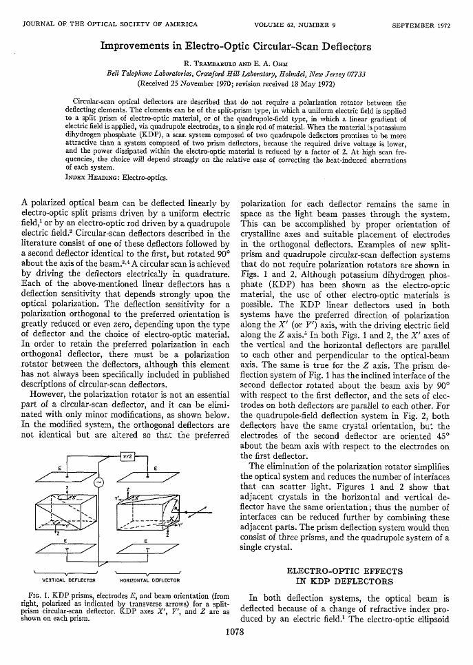
E | d E
Z Z
n YS,E E
VERTICAL DEFLECTOR HORIZONTAL DEFLECTOR
FIG. 1. KDP prisms, electrodes E, and beam orientation (fromright, polarized as indicated by transverse arrows) for a split-prism circular-scan deflector. KDP axes X', Y', and Z are asshown on each prism.
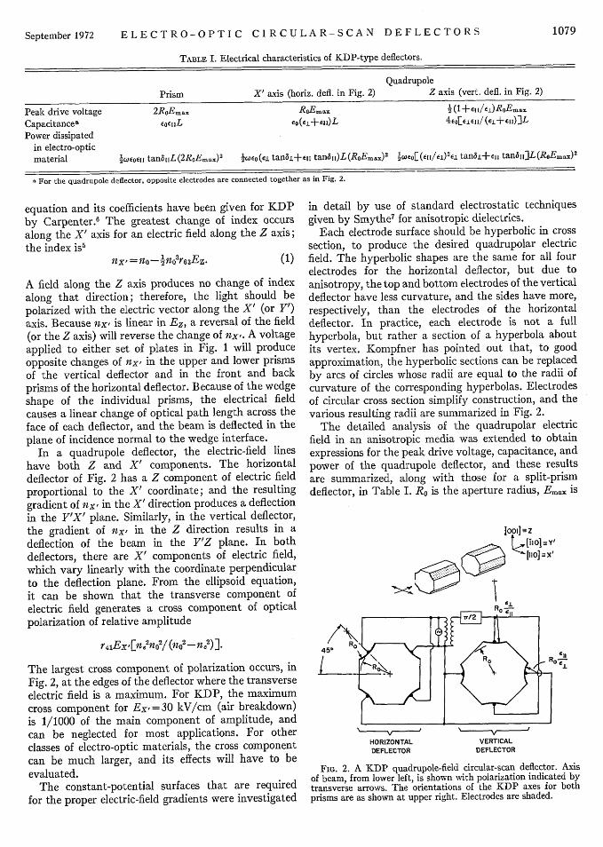
polarization for each deflector remains the same inspace as the light beam passes through the system.This can be accomplished by proper orientation ofcrystalline axes and suitable placement of electrodesin the orthogonal deflectors. Examples of new split-prism and quadrupole circular-scan deflection systemsthat do not require polarization rotators are shown inFigs. 1 and 2. Although potassium dihydrogen phos-phate (KDP) has been shown as the electro-opticmaterial, the use of other electro-optic materials ispossible. The KDP linear deflectors used in bothsystems have the preferred direction of polarizationalong the X' (or Y') axis, with the driving electric fieldalong the Z axis.5 In both Figs. 1 and 2, the XV axes ofthe vertical and the horizontal deflectors are parallelto each other and perpendicular to the optical-beamaxis. The same is true for the Z axis. The prism de-flection system of Fig. 1 has the inclined interface of thesecond deflector rotated about the beam axis by 900with respect to the first deflector, and the sets of elec-trodes on both deflectors are parallel to each other. Forthe quadrupole-field deflection system in Fig. 2, bothdeflectors have the same crystal orientation, but theelectrodes of the second deflector are oriented 450about the beam axis with respect to the electrodes onthe first deflector.
The elimination of the polarization rotator simplifiesthe optical system and reduces the number of interfacesthat can scatter light. Figures 1 and 2 show thatadjacent crystals in the horizontal and vertical de-flector have the same orientation; thus the number ofinterfaces can be reduced further by combining theseadjacent parts. The prism deflection system would thenconsist of three prisms, and the quadrupole system of asingle crystal.
ELECTRO-OPTIC EFFECTSIN KDP DEFLECTORS
In both deflection systems, the optical beam isdeflected because of a change of refractive index pro-duced by an electric field.' The electro-optic ellipsoid
1078
VOLUME 62, NUMBER 9 SEPTEM BER 1972
ELECTRO-OPTIC CIRCULAR-SCAN DEFLECTORS
TABLE I. Electrical characteristics of KDP-type deflectors.
Quadrupole
Prism X' axis (horiz. defi. in Fig. 2) Z axis (vert. defi. in Fig. 2)
Peak drive voltage 2RoEmax RoE max 4 (l+esu/,ERoEmax
Capacitances Eocji E(et++ei)L 4-o¶I(± ejj/(e.+siO)]L
Power dissipatedin electro-opticmaterial 4wJeoeul tandIL(2RsEmx)' PsowE(ei tan8±+eu tana 1 )L(RoEmax)' Pe1o[(ci e tan8±+e tan5IJ]L(RoEmax)'
a For the quadrupole deflector, opposite electrodes are connected together as in Fig. 2.
equation and its coefficients have been given for KDPby Carpenter.6 The greatest change of index occursalong the X' axis for an electric field along the Z axis;the index is5
nxt =no-4n03r63Ez. (1)
A field along the Z axis produces no change of indexalong that direction; therefore, the light should bepolarized with the electric vector along the X' (or Y')axis. Because nx. is linear in Ez, a reversal of the field(or the Z axis) will reverse the change of -x'. A voltageapplied to either set of plates in Fig. 1 will produceopposite changes of nx' in the upper and lower prismsof the vertical deflector and in the front and backprisms of the horizontal deflector. Because of the wedgeshape of the individual prisms, the electrical fieldcauses a linear change of optical path length across theface of each deflector, and the beam is deflected in theplane of incidence normal to the wedge interface.
In a quadrupole deflector, the electric-field lineshave both Z and X' components. The horizontaldeflector of Fig. 2 has a Z component of electric fieldproportional to the X' coordinate; and the resultinggradient of nx, in the X' direction produces a deflectionin the Y'X' plane. Similarly, in the vertical deflector,the gradient of nxx in the Z direction results in adeflection of the beam in the Y'Z plane. In bothdeflectors, there are X' components of electric field,which vary linearly with the coordinate perpendicularto the deflection plane. From the ellipsoid equation,it can be shown that the transverse component ofelectric field generates a cross component of opticalpolarization of relative amplitude
r,,Ex[ne2no 2/1(n 2 -ne 2 )].
The largest cross component of polarization occurs, inFig. 2, at the edges of the deflector where the transverseelectric field is a maximum. For KDP, the maximumcross component for Ex, =30 kV/cm (air breakdown)is 1/1000 of the main component of amplitude, andcan be neglected for most applications. For otherclasses of electro-optic materials, the cross componentcan be much larger, and its effects will have to beevaluated.
The constant-potential surfaces that are requiredfor the proper electric-field gradients were investigated
in detail by use of standard electrostatic techniquesgiven by Srnythe 7 for anisotropic dielectrics.
Each electrode surface should be hyperbolic in crosssection, to produce the desired quadrupolar electricfield. The hyperbolic shapes are the same for all fourelectrodes for the horizontal deflector, but due toanisotropy, the top and bottom electrodes of the verticaldeflector have less curvature, and the sides have more,respectively, than the electrodes of the horizontaldeflector. In practice, each electrode is not a fullhyperbola, but rather a section of a hyperbola aboutits vertex. Kompfner has pointed out that, to goodapproximation, the hyperbolic sections can be replacedby arcs of circles whose radii are equal to the radii ofcurvature of the corresponding hyperbolas. Electrodesof circular cross section simplify construction, and thevarious resulting radii are summarized in Fig. 2.
The detailed analysis of the quadrupolar electricfield in an anisotropic media was extended to obtainexpressions for the peak drive voltage, capacitance, andpower of the quadrupole deflector, and these resultsare summarized, along with those for a split-prismdeflector, in Table I. Ro is the aperture radius, Emax is
[001] =Z[ tIooiYz
45' R
HORIZONTAL VERTICALDEFLECTOR DEFLECTOR
FIG. 2. A KDP quadrupole-field circular-scan deflector. Axisof beam, from lower left, is shown with polarization indicated bytransverse arrows. The orientations of the KDP axes for bothprisms are as shown at upper right. Electrodes are shaded.
1079September 1972

R. TRAM BARULO AND E. A. OHM
the maximum Z component of electric field, L is thelength of each deflecting element (e.g., a vertical orhorizontal deflector), Eo is the dielectric constant offree space, and the subscripts of the relative dielectricconstant e, and loss tangent, tan8, refer to directionsparallel and perpendicular to the Z axis of KDP.
COMPARISON OF PRISM AND QUADRUPOLEDEFLECTION SYSTEMS
The driving characteristics and heat-induced aber-rations are of primary interest in a comparison of thetwo types of deflectors. To be meaningful, each de-flector should be capable of the same optical per-formance, which means that the deflections, apertureradii Ro, and lengths L, should be the same. Equaldeflections, in turn, require that the electric fieldsEmax be equal. Assuming these equalities, the electricalcharacteristics can be readily compared by insertingthe proper values of e into the expressions given inTable I.
As an example of a useful system, consider a circular-scan deflector that can cause a light beam to trace outa ring of six resolvable spots after one round tripthrough the deflectors. With a multipass technique,3
the number of spots can be increased to a large number,which is limited by interception of the beam at thedeflector edges or by aberrations. In a multipasssystem, the aberrations increase with the number ofpasses. Already serious at low scan frequencies, theyare the single most important obstacle to successfuloperation at high scan frequencies. The driving param-eters, which strongly affect the magnitude of theaberrations, can be put into perspective by consideringa multipass system that is scanned at a rate of 300mHz and can accommodate 100 spots on the last pass.The effects of aberrations are assumed to be correctable.The deflector dimensions are RO=1.4 mm and L=2.5cm. At X =6328A, the required driving electric fieldis Emax =20 kV/cm. The dielectric constants ofKDP are8 e,1 =20.2 and e1=44.3, and the correspond-ing loss tangents, from recent measurements at 300mHz by one of us (E. A. 0.), are tan II = 1.95 X10⁻⁴ andtan&L=1.27X10⁻⁴ . From the expressions in the table,the peak drive voltage, capacitance, and power dis-sipated in each KDP prism deflector are 5.6 kV, 4.5 pF,and 25.6 W, respectively. The corresponding values forand X'-axis quadrupole deflector are 2.8 kV, 14.3 pF,and 15.6 W, and for a Z-axis quadrupole deflector theyare 2.0 kV, 12.3 pF, and 8.4 W. For a split-prism cir-cular-scan system, which requires two prism deflectors,the total power is thus about 50 W, and for a quadrupolesystem, which requires one X'-axis and one Z-axisdeflector, the total power is 24 W.
From these results, it is readily apparent that largedrive voltages and moderate drive powers are needed
to operate each type of deflection system. For thequadrupole deflectors, the voltages are somewhatsmaller, but must drive larger capacitances. At higherscan frequencies, the capacitances are usually resonatedto obtain the desired voltages; as a consequence of thehigher capacitances, but lower step-up ratios, thepowers dissipated in the transformer and resonatorelements of a quadrupole deflector are approximatelyequal to those of a prism deflector.
The power dissipated in the electro-optic materialis of far greater consequence than losses in other partsof the circuit, because it produces thermal gradientsthat are great at moderate scan frequencies and increasewith increasing scan frequencies. These, in turn, pro-duce mechanical strains and refractive-index gradientsthat limit the number of spots in either a split-prism orquadrupole deflector system. If heat is withdrawn fromthe deflector mainly through the electrodes, the split-prism deflector is primarily defocused in one plane(astigmatism) but can be corrected with a nearbycylindrical lens. On the other hand, KDP quadrupoledeflectors have lower temperature gradients becausethe dissipated powers are lower and the heat flow isnearly circularly symmetric about the deflector axis.Because of the symmetry, the aberrations of quadrupoledeflectors (similar to spherical aberrations) can besubstantially corrected with nearby lenses havingspherical surfaces. At this time, it is not clear whichsystem would be the easiest to correct, or which wouldhave the smallest residual aberrations after correction.
In conclusion, the two deflection systems that havebeen described do not require a polarization rotator.The quadrupole system dissipates less drive power,has a heat flow that is nearly circularly symmetric,and has an aberration similar to spherical aberration.The split-prism deflection system, on the other hand,suffers considerably from astigmatism. The preferredsystem will probably be the one that has aberrationsthat are easier to correct.
ACKNOWLEDGMENTS
The authors wish to thank E. H. Turner and M. J.Gans for several helpful comments and suggestions.
REFERENCES
l For a review, see J. F. Lotspeich, IEEE Spectrum 5, 45 (1968).2 V. J. Fowler, C. F. Buhrer, and L. R. Bloom, Proc. IEEE 52,
193 (1964).3 W. V. Smith and D. G. Carlson, J. Opt. Soc. Am. 59, 108
(1969).4 V. J. Fowler and S. H. Maybar, U. S. Patent 3,363,102, Jan.
1968.5 A. Yariv, Quantum Electronics (Wiley, New York, 1967), pp.
300-306.R. O'B. Carpenter, J. Opt. Soc. Am. 40, 225 (1950).W. R. Smythe, Static and Dynamic Electricity, 2nd ed.
(McGrawlHill, New York, 1950), pp. 21, 22, 50.8 A. von Hippel, Dielectric Materials and Applications (Wiley,
New York, 1954), p. 301.
1080 Vol. 62