Embed Size (px)
Citation preview
IS 1382S : 19S3
WwibT Jnm ( Reaffirmed 1998)
huikm Shmdard
IMPROVING EARTHQUAKE RESISTANCE OFLOW STRENGTH MASONRY INJILDXNGS—
GUIDELINES
.
0 BIS 1993
BUREAU OF INDIAN STANDARDSMANAK BHAVAN, 9 BAHADIJR SHAH ZAFAR MARG
NEW DELHI 110002
August 1993
prke Group 6
Earthquake Engineering Sectional Committee, CED 39 .
FOREWORD
This Indian Standard was adopted by the Bureau of Indian Standards, after the draft finalized by the Earthquake Engineering Sectional Committee had been approved by the Civil Engineering Division Council.
Himalayan-Naga Lushai region, Indo-Gangetic Plain, Western India and Kutch and Kathiawar regions are geologically unstable parts of the country and some devastating earthquakes of the world have occurred there. A major part of the peninsular India, has also been visited by moderate earthquakes, but these were relatively few in number and had considerably lesser intensity. It has been a long felt need to rationalize the earthquake resistant design and construction of structures taking into account seismic data from studies of these Indian earthquakes, particularly in view of the heavy construction programme at present all over the country. It is to serve this purpose that IS 1893 : 1984 ‘Criteria for earthquake resis- tant design of structures’ was prepared. It lays down the seismic zones, the basic seismic coefficients and other factors and criteria for various structures. As an adjunct to IS 1893, IS 4326 Code of practice for earthquake resistant design and construction of buildings’ was prepared in 1967 and revised in 1976. This contained some recommendations for low strength brick and stone buildings. Earthquake damages to such buildings in Himachal Pradesh, North Bihar and Hill districts of Uttar Pradesh emphasized the need to expand these provisions. In order to assign the subject the importance it ~demanded in the context of prevalence of such buildings in the seismic zones It was therefore considered appropriate to issue a separate standard on the subject. It is naturally tied to IS 1893 in view of the seismic zgnes and coeffici- ents. It will be useful to read this standard along with IS 4326.
. The Sectional Committee responsible for the preparation of this standard has taken into consideration the views of all who are interested in this field and has related the standard to the prevailing practices in the country, Due weightage has also been given to the need for international co-ordination among the standards and practices prevailing in different countries of the world.
The Committee responsible-for the preparation of this standard is given at Annex A.
In the preparation of this standard, the publication ‘Guidelines for earthquake resistant non-engineered construction’, published by the International Association for Earthquake Engineering, Tokyo, October 1986, has been freely referred to.
IS 13828 : 1993
Indian Standard
IMPROVING EARTHQUAKE RESISTANCEOF LOW STRENGTHMASONRYBUILDINGS-
GUIDELINES 1 SCOPE
1.1 This standard covers the special features of design and construction for improving earthquake resistance of buildings of low-strength masonry.
1.1.1 The provisions of this standard are appli- cable in seismic zones III to V. No special provisions are considered necessary for buildings in seismic zones I and II.
1.1,2 The various provisions of IS 4326 : 1993 regarding general principles, special construction features, types of construction, categories of buildings and masonry construction with rect- angular masonry units are generally applicable to the masonry buildings of low strength dealt with in thin standard. There are however certain restrictions, exceptions and additional details which are specifically included herein. For com- pleteness however all necessary portions are repeated here.
NOTE -Attention is hereby drawn to the fact that low-strength masonry as dealt with herein will neither
qualify as engineered construction nor totally free from collapse in the severe seismic intensities VIII or IX. However, inclusion of special seismic design and construction features provided herein will raise thf,ir seismic resistance appreciably, reducing greatly the chances of collapse even in such seismic intencities.
2 REFERENCES
The following Indian Standards are necessary adjuncts to this standard:
IS Jvo.
1597 ( Part 1 ) : 1967
1893 : 1984
1964 : 1981
4326 : 1993
Code of practice for design and construction of founda- tions in soils : General requirements Code of practice for earth- quake resistant design and construction of buildings ( second renision )
3 TERMlNQLQGY
‘3.t~ For the purpose of this standard, the follow- ing definitions shall apply.
I
Tills
Code of practice for construc- tion of stone masonry : Part 1 Rubble stone masonry Criteria for earthquake resis- tant design of structures ( jifirst reuisian j
3.1 Low Strength Masonry
Includes fired brick work laid in clay mud mortar and random rubble; uncoursed, undressed or semi-dressed stone masonry in weak mortars; such as cement sand, lime-sand and clay mud.
3.2 Centre of Rigidity
The point in a structure where a lateral force shall be applied to produce equal deflections of its components at any one level in any particular direction.
3.3 Shear Wall
A wall designed to resist lateral force in its own plane. c
3.4 Box System
A bearing wall structure without a space frame the horizontal forces being resisted by the walls acting as shear walls.
3.5 Band
A reinforced concrete, reinforced brick or wooden runner provided horizontally in the walls to tie them together, and to impart horizontal bending strength in them.
3.6 Seismic Zone and Seismic Coefficient
The seismic zones I to V as classified and the corresponding basic seismic coefficient tzo, as specified in IS 1893 : 1984.
3.7 Design Seismic Coe5cient ( cch )
The value of horizontal seismic coefficient computed taking into account the soil foundation system and the importance factor as specified in 3.4.2.3(a) of IS 1893 : 1984.
3.8 Concrete Grades
28 days crushing strength of concrete cubes of 150 mm side in MPa, for example, for Ml5 grade concrete crushing strength 15 MPa.
4 GENERAL PRINCIPLES
4.0 General
The general principles given in 4.1 to 4.5 should be observed in the construction ~of buildings for improving their earthquake resistance.
IS 13828 : 1993
4.1 Lightness
Since the earthquake force is a function of mass, the building should be as light as possible consis- tent with structural safety and functional requirements. Roofs and upper storeys of buildings in particular should be designed as light as possible.
4.2 Continuity of Construction
4.2.1 As far as possible, all parts of the building should be tied together in such a manner that the building acts as one unit.
4.2.2 For integral action of building, roof and floor slabs should be continuous throughout as far as possible.
4.2.3 Additions and alterations to the structures should be accompanied by the provision of positive measures to establish continuity between the existing and the new construction.
4.3 Projecting and Suspended Parts
4.3.1 Projecting parts should be avoided as far as possible. If the projectmg parts cannot be avoid- ed, they should be properly reinforced and firmly tied to the main structure and their design should be in accordance with IS 1893 : 1981.
NOTE - In cases where stability of projecting parts against overturning is achieved by counterweight in the form of wall, slab etc, the overturnmg should be checked by increasing the weight of the projecting part and decreasing the weight of stabilizing mass simultaneously in accordance with the vertical seismic coefficient specified in 4.4.2 of IS 1893 : 1984.
4.3.2 Ceiling plaster should preferably be avoid- ed. When it is unavoidable, the plaster should be as thin as possible.
4.3.3 Suspended ceiling should be avoided as far as possible. Where provided, they should be light and adrquately framed and secured.
4.4 Shape of Building
In order to minimize torsion, the building should have a simple rectangular plan and be sym- metrical both with respect to mass and rigidity so that the centres of mass and rigidity of the building coincide with each other. It will be desirable to use separate blocks of rectangular shape particularly in seismic zones V and IV.
NOTE - For small buildings, minor asymmetry in plan and elevation may be ignored. Designing such buildings against torsion may bq difficult and uncertain.
4.5 Fire Safety
Fire frequently follows an earthquake and there- fore buildings should be constructed to make them fire resistant in accordance with the pro- visions of relevant Indian Standards for fire safety.
.
5 SPECIAL CONSTRUCTION FEATURES
5.1 Foundations
5.1.1 For the design of foundations, the provisions of IS 1901 : 1986 in conjunction with IS 1893 : 1981 shall generally be followed.
5.1.2 The subgrade below the entire area ot‘ the building should preferably be of the same type of the soil. Wherever this is not possible, the build- ings should preferably be separated into units and then the units should be located separately.
5.1.3 Loose fine sand soft silt and expansive clays should be avoided. If unavoidable the following measures may be taken to improve the soil on which the foundation of the building may rest:
a) Sand piling/under reamed piling/stone columns, etc.
b) Soil stabilization.
5.2 Roofs and Floors
5.2.1 Flat roof or floor should not preferably be made of tiles or ordinary bricks supported on steel, timber or reinforced concrete joists, nor they shall be of a type which in the event of an earthquake is likely to be loosened and parts or all of which may fall. If this type of construction cannot be avoided, the joists should be blocked at ends and bridged at intervals such that their spacing is not altered during an earthquake.
5.2.1.1 For pitched roofs, corrugated iron or asbestos sheets should be used in preference to country, Allahabad or Mangalore tiles or other loose roofing units. All roofing materials shall be properly tied to the supporting members. Heavy roofing materials should generally be avoided.
5.2.2 Pent Roofs
5.2.2.1 All roof trusses should be supported on and fixed to timber band reinforced concrete band or reinforced brick band. The holding down bolts should have adequate length as required for earthquake and wind forces.
Where a trussed roof adjoins a masonry gable, the ends of the purlins should be carried on and secured to a plate or bearer which should be adequately bolted to timber reinforced concrete or reinforced brick band at the top of gable end masonry.
5.2.2.2 At tie level, all the trusses and the gable end should be provided with diagonal braces in plan so as to transmit the lateral shear due to earthquake force to the gable walls acting as shear walls.
2
IS 13828’: 1993
5.2.3 Jack Arches
Jack arched roofs or floors where used should be provided with mild steel ties in _a11 spans along- with diagonal braces in plan to ensure diaphragm actions.
5.3 Staircases
5.3.1 The interconnection of the stairs with the adjacent floors should be appropriately treated by providing sliding joints at the stairs to eliminate their bracing effect on the floors. Ladders may be made fixed at one end and freely resting at the other.
5.3.2 Bd t- in Staircase
When stairs are built monolithically with floors, they can be protected against damage by provid- ing rigid walls at the stair opening. The walls enclosing the staircase should extend through the entire height of the stairs and to the building foundations.
6 BOX TYPE CONSTRUCTION
-This type of construction consists of prefabricated or in-s& masonry wall along with both the axes of the building. The walls support vertical loads and also act as shear walls for horizontal loads acting in any direction. All traditional masonry construction falls under this category. In pre- fabricated wall construction, attention should be paid to tht connections between wall panels so that transfer of shear between them is ensured.
7 CATEGORIES OF BUILDINGS
For the purpose of specifying the earthquake resisting features, the buildings, have been categorised in five categories A to E, as given in Table 1, based on the value of CC~, given by:
Qh = Q&
where
ah = design seismic coefficient for the building,
ug = basic seismic coefficient for the seismic
I=
P =
zone in which the building is located ( see Table 2 of IS 1893 : 1984 ),
importance factor applicable to the building ( see 3.4.2.3 of IS 1893 : 1984 ), and
soil foundation factor ( see 3.4.2.3 and Table 3 of IS 1893 : 1984 ).
8 LOW STRENGTH MASONRY CONSTRUCTION
8.1 General
B.l.l Two types of construction are included herein, namely:
a>
b)
Brick construction using weak mortar, and
Random rubble and half-dressed stone masonry construction using different mor- tars such as clay mud lime-sand and cement sand.
Table 1 Building Categories for Earthquake Resisting Features
( Clause 7 )
Category
A
B
C
Range of crh
0’04 to less than 0.05
0.05 to 0’06 ( both inclusive )
More than 0’06 but less than 0’08
D 0’08 to less than 0’12 E More than 0.12
NOTE - Low-strength masonry shall not be used for category E.
8.1.2 These constructions should not be permitted for important buildings with f >, 1.5 and should preferably be avoided for bullding category D ( see Table 1 ).
B.1.3 It will be useful to provide damp-proof course at plinth level to stop the rise of pore water into the superstructure.
8.1.4 Precautions should be taken to keep the rain water away from soaking into the wall so that the mortar is not softened due to wetness. An effective way is to take out roof projections beyond the walls by about 500 mm.
8.1.5 Use of a water-proof plaster on outside face of walls will enhance the life of the building and maintain its strength at the time of earthquake as well.
8.1.6 Ignoring tensile strength, free standing walls should be checked against overturning under the action of design seismic coefficient, ah, allowing for a factor of safety of 1 5.
8.2 Bridkwork in Weak Mortars
8.2.1 The fired bricks should have a compressive strength not less than 3.5 MPa. Strength of bricks and wall thickness should he selected for the total building height.
8.2.2 The mortar should be lime-sand ( 1 : 3 ) or clay mud of good quality. Where horizontal steel is used between courses, cement-sand mortar ( 1 : 3 ) should he used with thickness so as to cover the steel with 6 mm mortar above and below it. Where vertical steel is used, the surrounding brickwork of 1 x 1 or l& x 13
3
IS 13828 : I993
brick size depending on wall thickness should preferably be built using 1 : 6 cement-sand mortar.
8.2.3 The minimum wall thickness shall be one brick in one storey construction and one brick in top storey and 14 brick in bottom storeys of up to three storey construction. It should also not be less than l/16 of the length of wall between two consecutive perpendicular walls.
8.2.4 The height of the building shall be restrict- ed to the following, where each storey height shall not exceed 3.0 m:
For Categories A, B and C - three storeys with flat roof; and two storeys plu; attic pitched roof.
For Category D - two storeys with flat roof; and one sto- rey plus attic for pitched roof.
8.2.5 Special Bond in Brick Walls
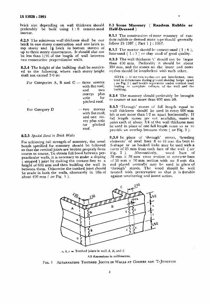
For achieving fuli strength of masonry, the usual bonds specified for masonry should be followed so that the vertical joints are broken properly from course to course. To obtain full bond between per- pendicular walls, it is necessary to make a sloping ( stepped ) joint by making the corners first to a height of 600 mm and then building the wall in between them. Otherwise the toothed joint should be made in both the walls, alternately in lifts of about 450 mm ( see Fig. 1 ).
8.3 Stone Masonry ( Random Rubble or Half-Dressed )
8.3.1 The construction ofstone masonry of ran- dom rubble or dressed stone type should generally follow IS 1597 ( Part 1 ) : 1967.
8.3.2 The mortar should bc cement-sand ( 1 : 6 ), lime-sand ( 1 : 3 ) or clay mud of good quality.
3.3.3 The wall thickness ‘t’ should not be larger than 450 mm. Preferably it should be about 350 mm, and the stones on the inner and outer wythes should be interlocked with each other.
NOTE - If the two wthes are not interlocked, they tend to delaminate during ground shaking bulge’ apait ( see Fig. 2 ) and bwkle separately under vertical load leading to complete collapse of the wall and the building.
8.3.4 The masonry should preferably be brought to courses at not more than 600 mm lift.
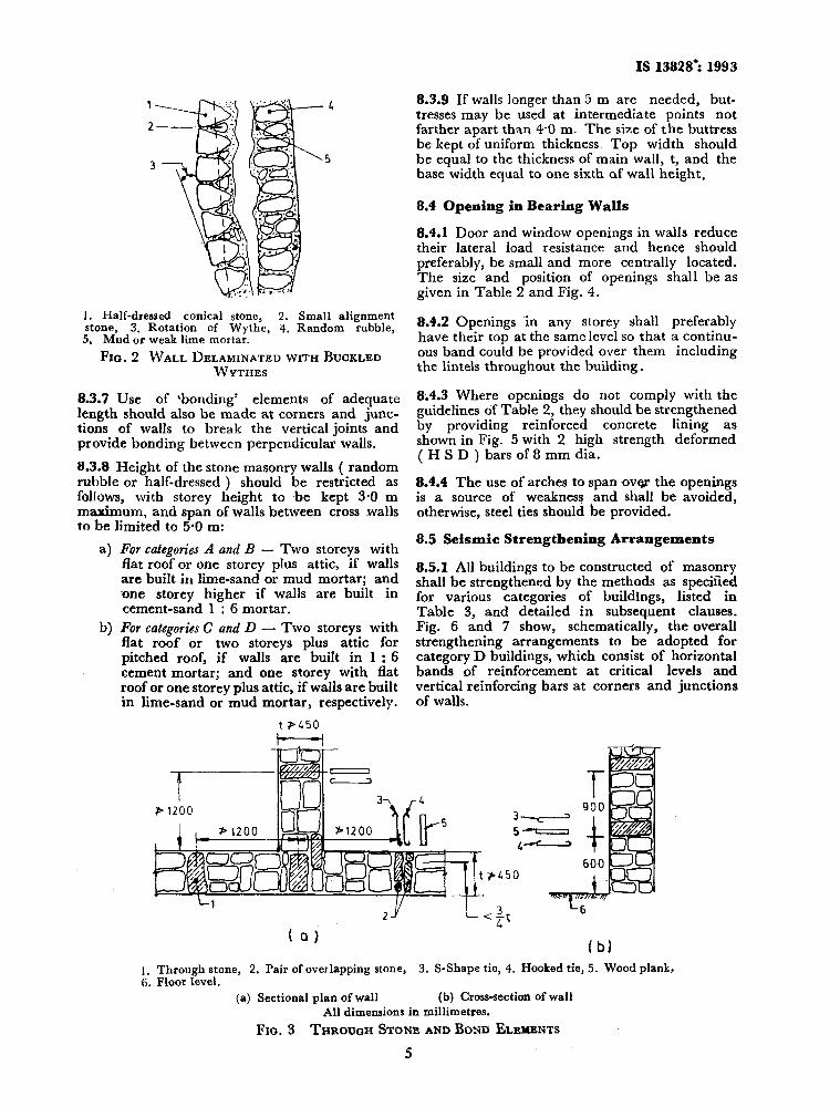
8.3.5 ‘Through’ stones at‘ full length equal to wall thickness should be used in every 600 mm lift at not more than 1.2 m apart horizontally. If full length stones are not available, stones in pairs each of about 314 of the wall thickness may be used in place of one full length stone so as to provide an overlap betlveen them ( see Fig. 3 ).
8.3.6 In place of (through’ stones, ‘bonding elements’ of steel bars 8 to 10 mm dia~bent to S-shape or as hooked links may be used with a cover of 25 mm from each face of the wall ( see Fig. 3 ). Alternatively, wood ~bars of 38 mm x 38 mm cross section or concrete bars of 50 mm x 50 mm section with an 8 mm dia rod placed centrally may be used in place of *through’ stones. The wood should be well treated wit’n preservative so that it is durable against weathering and insect action.
a, b, c = Toothed joints in wall A, B, and C
All dimensions in millimetres.
FIG. 1 ALTERNATING TOOTHED JOINTS IN WALLS AT CORNER AND T-JUNC~IOX
4
IS 13828’ 1993
1. Half-dressed conical stone, 2. Small alignment stone, 3. Rotation of Wythe, 4. Random rubble,
5. Mud or weak lime mortar.
Fro. 2 WALL DELAMINATEDWITHBUCKLED WYTHE~
8.3.7 Use of ‘bonding’ elements of adequate length should also be made at corners and junc- tions of walls to break the vertical joints and provide bonding between perpendicular walls.
8.3.8 Height of the stone masonry walls ( random rubble or half-dressed ) should be restricted as follows, with storey height to Abe kept 3.0 m maximum, and span of walls between cross walls to be limited to 5.0 m:
a>
b)
For categories A and B - Two storeys with flat roof or one storey plus attic, if walls are built in lime-sand or mud mortar; and -one storey higher if walls are built in cement-sand 1 : 6 mortar. For categories C and D - Two storeys with flat roof or two storeys plus attic for pitched roof, if walls are built in 1 : 6 cement mortar; and one storey with flat roof or one storey plus attic, if walls are built in lime-sand or mud mortar, respectively.
t PL50
--L!- I-
8.3.9 If walls longer than 5 m are needed, but- tresses may be used at intermediate points not farther apart than 4.0 m. The size of the buttress be kept of uniform thickness. Top width should be equal to the thickness of main wall, t, and the base width equal to one sixth of wall height.
8.4 Opening in Bearing Walls
8.4.1 Door and window openings in walls reduce their lateral load resistance and hence should preferably, be small and more centrally located. The size and position of openings shall be as given in Table 2 and Fig. 4.
8.4.2 Openings in any storey shall preferably have their top at the same level so that a continu- ous band could be provided over them including the lintels throughout the building.
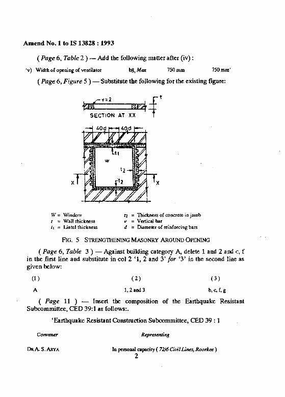
8.4.3 Where openings do not comply with the guidelines of Table 2, they should be strengthened by providing reinforced concrete lining as shown in Fig. 5 with 2 high strength deformed ( H S D ) bars of 8 mm dia.
8.4.4 The use of arches to span over the openings is a source of weakness and shall be avoided, otherwise, steel ties should be provided.
8.5 Seismic Strengthening Arrangements
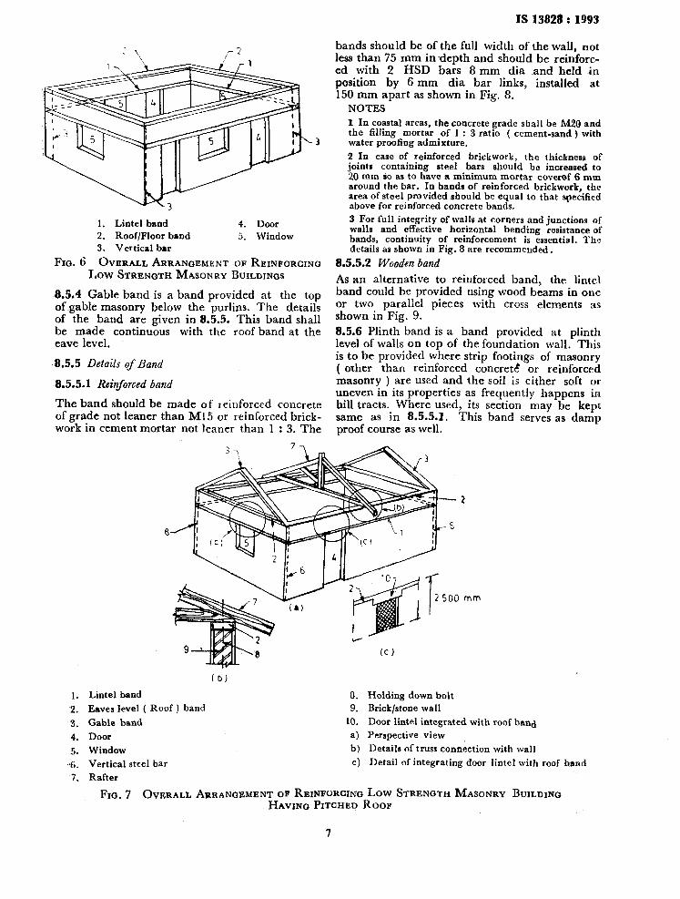
8.5.1 All buildings to be constructed of masonry shall be strengthened by the methods as specified for various categories of buildings, listed in Table 3, and detailed in subsequent clauses. Fig. 6 and 7 show, schematically, the overall strengthening arrangements to be adopted for category D buildings, which consist of horizontal bands of reinforcement at critical levels and vertical reinforcing bars at corners and junctions of walls.
21 ”
(0) (b)
1. Through stone, 2. Pair of overlapping stone, 3. S-Shape tie, 4. Hooked tie, 5. Wood plank, 6. Floor level.
(a) Sectional plan of wall (b) Cross-section of wall
All dimensions in millimetres.
Fxa. 3 THROU~HSTONEANDBOND ELEMENTS
5
IS 13828 : 1993 .
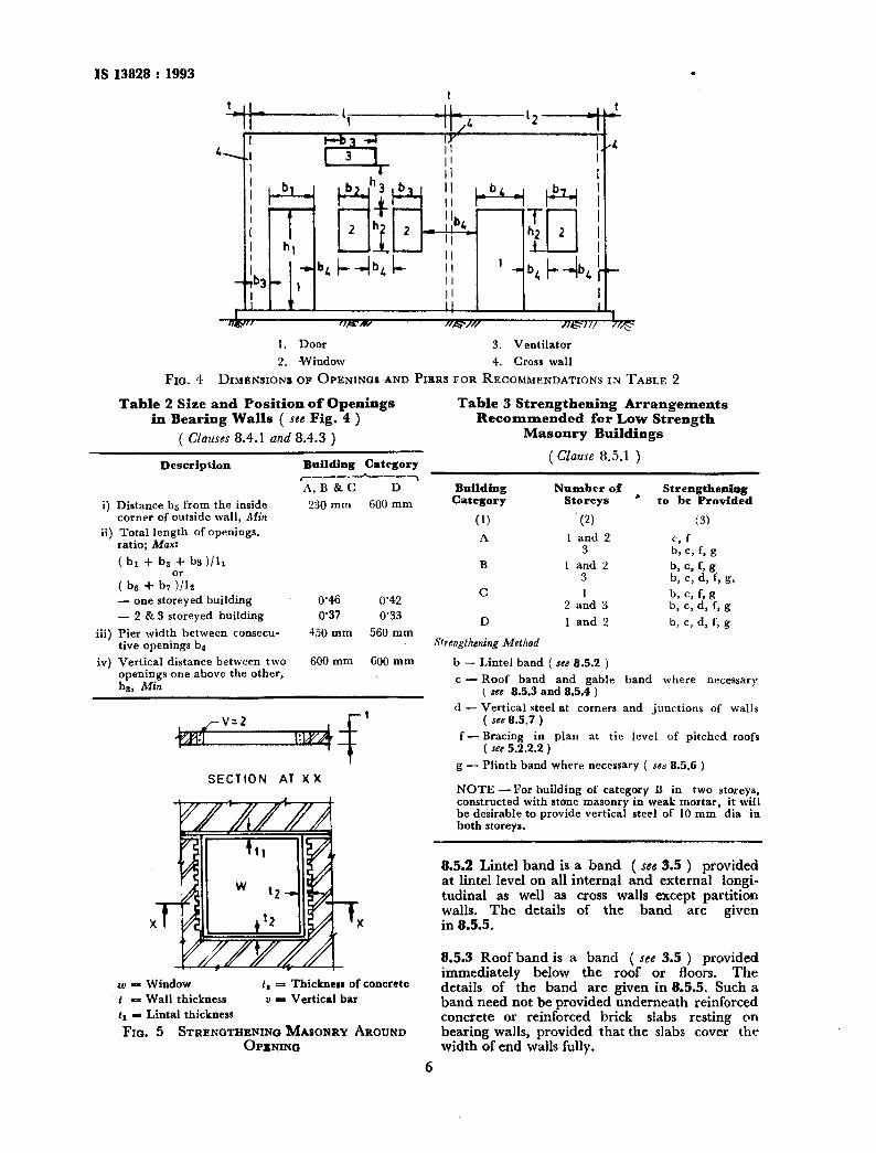
1. Door 3. Ventilator
2. Window 4. Cross wall
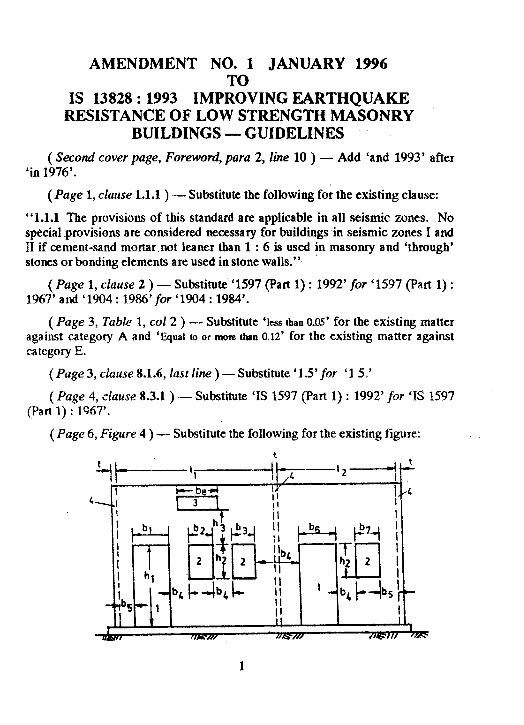
FIG. 4 DIMENSIONS OF OPENINCIS AND PIERS FOR RECOMMENDATIONS IN TABLE 2
Table 2 Size and Position of Openings Table 3 Strengthening Arrangements in Bearing Walls ( see Fig. 4 ) Recommended for Low Strength
( Clauses 8.4.1 and 8.4.3 ) Masonry Buildings
Description Building Category ( Clause 8.5.1 )
#_____h___~ A,B &C D Building Number of
c Strengthenhg
to be Provided i) Distance bs from the inside corner of outside wall, Alin
ii) Total length of openings. ratio; Max:
230 mm 600 mm Category Storeys
(1) (2)
A 1 and 2 3
(3)
c, f b> c, f, 8
b, c, f, g b, c, 4 C g,
b, c, f, 8 b, c, d, f, g
b> c, 4 f, g
( br + ba + h )I”I
( be + b,%a - one storeyed building - 2 & 3 storeyed building
iii) Pier width between consecu- five openings b4
0’46 0’42 0’37 0’33
450 mm 560 mm
iv) Vertical distance between two 600 mm 600 mm openings one above the other, hs, Min
4-f t
SECTION AT XX
w = Window t = Wall thickness tS = Lintal thickness
t, = Thickness of concrete u = Vertical bar
FIG. 5 STRENGTHENING MASONRY AROUND OPENING
B
C
D
1 and 2 3
2 aid 3
1 and 2
Strengthening Method
b - Lintel band ( see 8.5.2 )
c - Ro-of band and gable ( see 8.5.3 and 8.5.4 )
d - Vertical steel at corners ( see 8.5.7 )
band where necessary
and junctions of walls
f-Bracing in plan at tie level of pitched roofs ( see 5.2.2.2 )
g - Plinth band where necessary ( seti 8.5.6 )
NOTE -For building of category B in two storeys, constructed with stone masonry in weak mortar, it will be-desirable to provide vertical steel of 10 mm dia in both storeys.
8.5.2 Lintel band is a band ( see 3.5 ) provided at lintel level on all internal and external longi- tudinal as well as cross walls except partition walls. The details of the band are given in 8.5.5.
8.5.3 Roof band is a band ( see 3.5 ) provided immediately below the roof or floors, The details of the band are given in 8.5.5. Such a band need not be provided underneath reinforced concrete or reinforced brick slabs resting on bearing walls, provided that the slabs cover the width of end walls fully.
6
IS I3828 : 1993
3
1. Lintel band
2. Roof/Floor band
3. Vertical bar
4. Door
5. Window
FIG. 6 OVERALL ARRANGEMENT OF REINFORCING Low STRENGTH MASONRY BUILDINGS
,8.5.4 Gable band is a band provided at the top of-gable masonry below the purlins. The details of the band are given in 8.5.5. This band shall be made continuous with the roof band at the eave level.
8.5.5 Details of Band
8.5.5.1 Reinforced band
The band should be made of reinforced concrete of grade nQt leaner than Ml5 or reinforced brick- work in cement mortar not leaner than 1 : 3. The
bands should be of the full width Qf the wall, not less than 75 mm indepth and should be reinforc- ed with 2 HSD bars 8 mm dia land held in position by 6 mm dia bar links, installed at 150 mm apart as shown in Fig. 8.
NOTES 1 In coastal areas, the concrete grade shall be M20 and the filling mortar of 1 : 3 ratio ( cement-sand) with water proofing admixture.
2 In case of reinforced brickwork, the thickness of joints containing steel bars should be increased to 20 mm so as to have a minimum mortar coverof 6 mm around the bar. In bands of reinforced brickwork, the area of steel provided should be equal to that specified above for reinforced concrete bands.
3 For full integrity of walls at corners and junctions of walls and effective horizontal bending resistance of bands, continuity of reinforcement is essential. The details as shown in Fig. 8 are recommended.
8.5.5.2 Wooden band
As an alternative to reinforced band, the lintel band could be provided using wood beams in one or two parallel pieces with cross elements as shown in Fig. 9. 8.5.6 Plinth band is a band provided at plinth level of walls on top of the foundation wall, This is to be provided where strip footings of masonry ( other than reinforced concrete! or reinforced masonry ) are used and the soil is either soft or uneven in its properties as frequently happens in hill tracts. Where used, its section may be kept same as in 8.5.5-l. This band serves as damp proof course as well.
(b)
1. Lintel band 8.
2. Eaves level ( Roof ) band 9.
3. Gable band
4. Door
5. Window
6. Vertical steel bar
7. Rafter
FIG. 7 OVERALL
10.
a) b) cl
Holding down bolt
Brick/stone wall
Door lintel integrated with roof hand
Perspective view
Details of truss conn&tion with wall
Detail of integrating door lintel with roof band
ARRANGEMENT OF REINFORCING LOW STRENGTH MASONRY BUILDING
HAVING PITCHED ROOF
7
IS 13828 : 1993 .
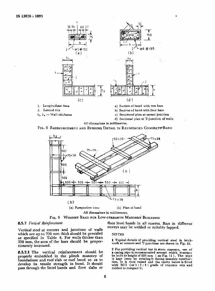
1
30 6u 60 30
+Jtm-ttJ
I b
(d 1
1. Longitudinal bars
2. Lateral ties
br, b, - Wall thickness
a) Section of band with two bars
b) Section of band with four bars
c) Structural plan at corner junction
d) Sectional plan at T-junction of walls
All dimensions in millimetres.
Fro. 8 REINFORCEMENT AND BENDING DETAIL IN REINFORCED CONCRETIPBAND
(a) Perspective view (b) Plan of band
All dimensions in millimetres.
FIG. 9 WOODEN BAND FOR LOW-STREONTH MASONRY BUILDINGS
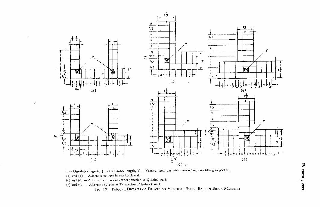
8.5.7 Vertical Rhforcement floor level bands in all storevs. Bars in different-
Vertical steel at corners and junctions of walls storeys may be welded or suitably lapped.
which are up to 350 mm thick should be provided NOTES as specified in Table 4. For walls thicker than 350 mm, the area of the bars should be propor- 1 Typical details of providing vertical steel in brick-
tionately increased. work at corners and T-junctions are shown in Fig. 10.
8.5.7.1 The vertical reinforcement should be properly embedded in the plinth masonry of foundations and roof slab or roof band so as to develop its tensile strength in bond. It should pass through the lintel bands and floor slabs or
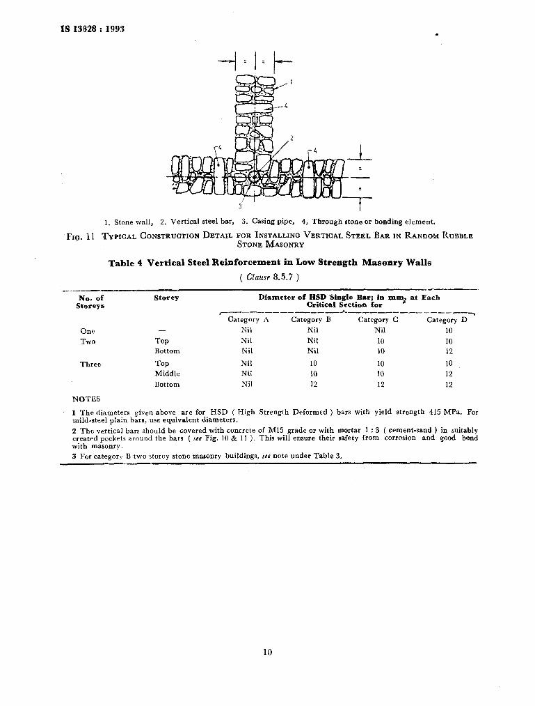
2 For providing vertical bar in stone masonry, use of a casing pipe is recommended around which masonry be builtto height of 600 mm ( suu Fig. 11 ). The pipe is kept loose by rotating it during masonry conatruc- tion. It is then raised and the cavity below is filled with Ml5 (or 1 : 2 : 4 ) grade of concrete mix and rodded to compact it.
8
6
,_/-
-
_I-
I.,-
-. -
4 z-
N!-
E66
I ?
8tSE
t Si
IS 13828 : 1993 .
1. Stone wall, 2. Vertical steel bar, 3. Casing pipe, 4, Through stone or bonding element.
Fro. 11 TYPICAL CONSTRUCTION DETAIL FOR INSTALLINQ VERTICAL STEEL BAR IN RANDOM RUBBLE STONE MASONRY
Table 4 Vertical Steel Reinforcement in Low Strength Masonry Walls
( Clause 8.5.7 ) _w,_.y__-
No. of Storeye
One
Two
Three
NOTES
Storey
-
Top Bottom
Top Middle
Bottom
Diameter of HSD Single Bar; in mxnt at Each Critical Section for
c--_--------____ h_-_,------ ___‘___~ Category A Category B Category C Category D
Nil Nil Nil 10
Nil Nil 10 10
Nil Nil 10 12
Nil 10 10 10
Nil IO 10 12
Nil 12 12 12
1 The diameters given above are for HSD ( High Strength Deformed ) bars with yield strength 415 MPa. For mild-steel plain bars, use equivalent diameters.
2 The vertical bars should be covered with concrete of Ml5 grade or with mortar 1 : 3 ( cement-sand ) in suitably created pockets around the bars ( see Fig. 10 & 11 ). This will ensure their safety from corrosion and good bond with masonry.
3 For category B two storey stone masonry buildings, sfe note under Table 3.
IS 13828 : J993
ANNEX A
( Foreword )
COMMITTEE COMPOSITION
Earthquake Engineering Sectional Committee, CED 39
Members
Chairman
DR A. S. ARYA 7216 Civil Lines, Roorkee
Refirascnting
SEIRI 0. P. AQQA~WAL SHRI G. SHARAN ( Alternate )
DR K. G. BHATIA DR C. KAMESHWARA RAO ( Alternate I ) SERI A. K. SIN~H ( Alturnata II )
SBRI S. C. BHATIA Da B. K. RASTOUI (Alternate )
Dn A. R. CHANDRASEKARAN
Indian Roads Congress, New Delhi
DR B~IJESH CHANDRA ( Alfcrnatc I ) DR B. V. K. LAVANIA ( Alternate II )
DR S. N. CHATTERJEE Snnr S. K. NAo (Alternate 1
SHRI K. T. CHAUBAL DR B. K. PAUL ( Alternate )
DR A. V. CEUM~~AR DR S. K. KAUSHIK ( Alternate I
Bharat Heavy Electricals Ltd, New Delhi
National Geophysical Research Institute ( CSIR ), Hyderabad
Department of Earthquake Engineering, University of Roorkee, Roorkee
Indian Meteorological Department, New Delhi
North Eastern Council, Shillong
Indian Society of Earthquake Technology, Roorkee
DIREOTOR EXBANK~~I~N~ ( N & W ‘) Central Water Commission ( ERDD ), New Deihi DIRECTOR CMDD ( NW & S ) ( Alternate) +
DIRECTOl~ STANDARDS ( B & S ), RDSO Railway Board, Ministry of Railways JOINT DIRECTOR STANDARDS ( B & S ) CB-I, RDSO. LUCKNOW ( Alternate 1
MISS E. D)IVATIA ’ ’ SARI C. R. VBNKATESBA ( Alternate )
DR S. K. JAIN DR V. K. GUPTA ( Alternate )
SH~I 1. D. G~PTA SERI J. G. PADALE ( Alternate )
SHIU V. K. KULKARNI SHHI P. C. KOTESWAR A RAO ( Alternate )
SRRI V. KUaXAR SHRI R. S. BAJAJ ( Alternate )
SBRI M. Z. KURII~N SHXI K. V. SUBRAMANIAN ( Alternate )
SHRI A. K. LAL. SHRI T. R. BRATIA ( Alternate )
SHRI S. K. MITTAL SRRI S. S. NARAXQ SHRI A. D. NARIAN
SERI 0. P. A~~ARWAL ( Alternate ) SHRI P. L. NARULA
SHRI A. K. SRIVASTAVA ( Alternate ) RESEARCH OFFICER DR D. SENGUPTA
SHRI R. K. GBOVER ( Alternate ) DR R. D. SK .%RMA
SHRI U. S. P. VERMA ( Alternate ) COL R. K. S~NQH
LT COL B. D. BHATTOPXDHYAYA ( Alternate )
D R P. SRINIVASULU DR N. LAESHMANAN ( Alternate )
SUPERINTENDINO ENQINEER ( D ) EXECUTIVE ENGINEER
DR A. N. TANDOX SHRI Y. R. T~NEJA,
( D ) II ( Altcrnatt ,
Director ( Civ Engg )
National Hydro-Electric Power Corporation Ltd, New Delhi
Indian Institute of Technology, Kanpur
Central Water & Power Research Station, Pune
Department of Atomic Energy, Bombay
National Thermal Power Corporation Ltd, New Delhi
Tata Consulting Engineers, Bombay
National Buildings Organization, New Delhi
Central Building Research Institute, Roorkee Central Water Commission ( CMDD ), New Delhi Ministry of Transport, Department of Surface Transport ( Roads
Wing ), New Drlhi Geological Survey of India, Calcutta
Irrigation Department, Govt of Maharashtra. Nasik Engmeers India Ltd, New Delhi
Nuclear Power Corporation, Bombay
Engineer-in-Chief’s Branch, Army Headquarters. New Delhi
Structural Engineering Research Centre ( CSIR ); Madras
Central Public Works Department, New Delhi !l
In personal capacity ( B-7150 Safdarjung Development Area, New Delhi ) Director General, BIS ( Ex-o&i0 Member )
Member-Secretary
SHRI S. S. SETHI Director ( Civ Engg ), BIS
11
.
Standard Mark The use of the Standard Mark is governed by the provisions of the Bureau of Indian
Standards Act, 1986 and the Rules and Regulations made thereunder. The Standard Mark on products covered by an Indian Standard conveys the assurance that they have been produced to comply with the requirements of that standard under a well defined system of inspectian, testing and quality control which is devised and supervised by BIS and operated by the producer. Standard marked products are also continuously checked by BIS for con- formity to that standard as a further safeguard. Details of conditions under which a licence for the use of the Standard Mark may be granted to manufacturers or producers may be obtained from the Bureau of Indian Standards.
Bureau of ludiM Staududs
BIS is a statutory institution established under the Bureau of Indian Standards Act, 1986 to promote’ harmonious development of the activities of standardization, marking and quality certification of . goods and attending to connected matters in the country.
Copyright
BIS has the copyright of all its publications. No part of these publications may be reproduced in any form without the prior permission in writing of BIS. This does not preclude the free use, in the course of implementing the standard, of necessary details, such as symbols and sizes, type or grade designations. Enquiries relating to copyright be addressed to the Director ( Publications ), BIS.
Review of Indian Standards
Amendments are issued to standards as the need arises on the basis of comments. Standards are also reviewed periodically; a standard along with amendments is reaffirmed when such review indicates that no changes are needed; if the review indicates that changes are needed, it is taken up for revision. Users of Indian Standards should ascertain that they are in possession of the latest amendments or edition by referring to the latest issue of ‘BIS Handbook’ and Standards Monthly Addition-s’. Comments on this Indian Standard may be sent to BIS giving the following reference:
Dot : No. CED 39 ( 5269 ) I*
’ ?’
AmendmenWIssued Since Publication
Amend No. Date of Issue .
, Text Affected
BUREAU OF INDIAN STANDARDS
Headquarters:
Manak Bhavan, 9 Bahadur Shah Zafar Marg, New Delhi 110002 Telephones : 331 01 31, 331 13 75
Telegrams : Manaksanstha ( Common to all of&es )
Regional Offices :
Central : Manak Bhavan, 9 Bahadur Shah Zafar Marg NEW DELHI, 110002
Eastern : l/14 C. I. T. Scheme VII M, V. I. P. Road, Maniktola CALCUTTA 700054
Northern : SC0 445-446, Sector 35-C, CHANDIGARH 160036
Southern : C. I. T. Campus, IV Cross Road, MADRAS 600113
Telephone
- ( 01 31 F’ i.
321 431 13 75
37 84 99, 37 85 61 37 86 26, 37 86 62
I 53 38 43, 53 16 40 53 23 84
235 02 16, 235 04 42 235 15 19, 235 23 15
Western : Manakalaya, E9 MIDC, Marol, Andheri ( East ) 632 92 95, 632 78 58 BOMBAY 400093 632 78 91, 632 78 92
Branches : AHMADABAD. BANGALORE. BHOPAL. BHUBANESHWAR. COIMBATORE. FARIDABAD. GHAZIABAD. GUWAHATI. HYDERABAD. IAIPUR. KANPUR. LUCKNOW. PATNA. THIRUVANANTHAPURAM.
.
AMENDMENT NO. 1 JANUARY 1996
I§ 13828 : 1993 IMP::VING EARTHQUAKE RESISTANCE OF LOW STRENGTH MASONRY
BUILDINGS - GUIDELINES
( Second cover page, Foreword, para 2, line 10 ) - Add ‘and 1993’ after ‘in 1976’.
( Page 1, clause 1.1 .l ) -Substitute the following for the existing clause:
“1.1.1 The provisions of this standard are applicable in all seismic zones. No special provisions are considered necessary for buildings in seismic zones I and II if cement-sand mortar not leaner than 1 : 6 is used in masonry and ‘through’ stones or bonding elements are used in stone walls.”
(Page 1, clause 2 ) - Substitute ‘1597 (Part 1) : 1992’ for ‘1597 (Part 1) : 1967’ and ‘1904 : 1986’for ‘1904 : 1984’.
( Page 3, Tuble 1, coZ2 ) - Substitute ‘less than OLt.5’ for the existing matter against category A and ‘bpai to or more than 0.12’ for the existing matter against category E.
(Page 3, clause 8.1.6, last line )-Substitute ‘1.5’for ‘15.’
( P6zge 4, ciause 8.3.1 ) - Substitute ‘IS 1597 (Part 1) : 1992’ for ‘IS 1597 (Part 1) : 1967’.
r (Page 6, Figure 4 ) - Substitute the following for the existing figure:
t
Amend No. 1 to IS 13828 : 1993
(Page 6, Table 2 ) -Add the following matter after (iv) :
‘v) Width of opening of ventilator b8, Max 1.50 mm 750 mm’
( Page 6, Figure 5 ) - Substitute the following for the existing figure:
SECTION AT XX
‘tv= Window Q = Tbickoess of cxmcrete ia jamb t = Wall thickness v = Vertical bar t: = Lintel thickness d = Diameter of reinforcing bars
FIG. 5 STRJNGTHENING M&GQNRY AROUND OPENING
( Page 6, Table 3 ) - Against building category A, delete 1 and 2 and 6, f in the first line and substitute in co1 2 ‘1, 2 and 3’ for ‘3’ in tbe second line as given below:
(1) (2) (3)
A 1,2aod3 b, c, f, g
( Page 11 ) - Insert tbe composition of the Eatiquake Resistant Subcommittee, CED 39:l as follows:.
‘Earthquake Resistant Construction Subcommittee, CED 39 : 1
co-r Represeating
DRA. S.ARYA In personal capacity ( 72/6 Civil&es, Rode) 2
Memhrs
SW N. # BHAITACXARYA
SW B. K. CHA~OLABORIY SHRI D. P. SINM (rQlti&)
Sm D. N. GWXAL
D~Smmu K JAW DR k S. R SAG (Alfanoie)
SHRI M. P. LUSIPJGH
JOINT I)iRKXOR STAMARDS (B&s) m-1 Assn DIRECIW ( B 8r S ) CB-1
(A&mate )
Amend No. 1 to IS 13828 : 1993
Representing
Engineer-in-Chief’s Branch, New Delhi
Housing and Urban Development Corporation, New Delhi
North Eastern Council, Shillong
Indian IRFltute of Technology, Kattpur
Central Buildings Research Institute, Roorkee
Railway Board, Ministry of Railways
Public Works Department, Govt of Himachal Pradesh, Shimla
*Hindustan Prefab Limited, New Delhi
National l3uildings Qrgaaeization, New Delhi
University of Roo~kee, Department of Earthquake Engineering, Roorkee
DR(MRS,P R. Bos~(Al~nnate)
SfcHJG. M. SHocEmfli Public Waaks Ilcprlmmt, Jammu & Kashmir
DR P. SRtNTvAsULtJ Structural Engineering Research Centre f CSIR ), Madras
Da N. ~4KSNMA_VAN ( tikemclte )
§Mxl SUSRATA tc%AmAVAraW Public Works Department, Govermnent of Assam, Guwabati
§:IPEM+~~FX~ EMXMZE~A ( DESCY) Public Works Department, Government of Gujmt r
SLVE~DLWS~R~OR~F Centera! F’uMic Works Department, New Delhi WORKS (NDZ)
slJPF.~~DlNG EMZNRFX (D) ( Alfmtair )
(CED39) Reprography Unit, BIS, New Delhi, India
3
AMENDMENT NO. 2 APRIL 2002
IS 13828:1993 IMPi%’ING EARTHQUAKERESISTANCE OF LOW STRENGTH MASONRY
BUILDINGS — GUIDELINES
[ Pa<qe 1, clause 1.1.1 ( see also Amendment No. 1 ) ] — Substitute ‘zoneII” for ‘zones I and 11’
( Page 1, clause 3.6) — Substitute the following for the existing:
‘3.6 Seismic Zone and Seismic Coefficient
The seismic zones 11 to V as classified and the corresponding zone factors asspecified in 6.4.2 (Table 2) of IS 1893 (Part 1).’
( Page 1, clause 3.7) — Substitute the following for the existing:
‘3.7 Zone Factor (Z)
It is a factor to obtain the design spectrum depending on the perceived maximumseismic risk characterized by maximum considered earthquake (MCE) in thezone in which the structure is beak-d.’
( CED 39 )
ReprographyUnit, BIS, New Delhi, India