Embed Size (px)
Citation preview
IMPROVING STEEP-SLOPE PIPELINE CONSTRUCTION TO
REDUCE IMPACTS TO NATURAL RESOURCES
A REPORT PRODUCED THROUGH A COLLABORATION BETWEEN
Dominion Energy Enbridge EQT Midstream Partners
Kinder Morgan NiSource Southern Company Gas
UGI Energy Services Williams
FACILITATED BY
The Nature Conservancy

Acknowledgements:
The project sponsors appreciate the experience and knowledge contributed by the many subject matter experts to improve the accuracy and rigor of this report including Duraroot Environmental Consulting, Golder Associates,
Groundwater & Environmental Services, Inc., and Williams Forestry and Associates.
This work was supported in part through a grant from the Hillman Foundation.
Table of Contents 1 INTRODUCTION AND EXECUTIVE SUMMARY .....................................................................................................1
1.1 Background .................................................................................................................................................1
1.2 Formation of a Collaborative Project Team ...............................................................................................1
1.3 Project Objectives .......................................................................................................................................1
1.4 Project Process ...........................................................................................................................................2
1.5 Report Structure & Organization of Best Practices ....................................................................................2
1.6 Limitations ..................................................................................................................................................3
2 PRE-CONSTRUCTION PHASE ...............................................................................................................................4
2.1 BEST PRACTICES ..........................................................................................................................................4
2.1.1 Perform a Geohazard Assessment to Identify High-Hazard Landslide/Erosion Areas .......................4
2.1.2 Develop Site-Specific Plans for High Landslide Potential and Erosion-Prone Slopes .........................6
2.1.3 Accurately Identify Water Features Prior to Construction .................................................................8
2.1.4 Identify Locations Where Civil or Geotechnical Mitigation Measures are Needed to Minimize Slope Movement ................................................................................................................................................9
2.1.5 Develop Site-Specific Reclamation and Revegetation Strategies .................................................... 11
2.2 POTENTIAL BEST PRACTICES .................................................................................................................... 13
2.2.1 Potential Best Practice: Optimize Extent of Disturbed Area on High Landslide Potential and Erosion-Prone Slopes ....................................................................................................................................... 13
2.2.2 Potential Best Practice: Evaluate Environmental Performance of Contractors .............................. 13
3 CONSTRUCTION AND RESTORATION PHASES ................................................................................................. 15
3.1 BEST PRACTICES ....................................................................................................................................... 15
3.1.1 Ensure Optimal Placement and Installation of Slope Breakers ....................................................... 15
3.1.2 Optimize Groundwater Management During Construction and Restoration ................................. 17
3.1.3 Utilize Hydroseeding and Hydromulching for Vegetative Restoration ........................................... 19
3.2 POTENTIAL BEST PRACTICE ...................................................................................................................... 21
3.2.1 Potential Best Practice: Optimize Vegetative Preservation ............................................................ 21
4 OPERATIONS AND MAINTENANCE PHASE....................................................................................................... 22
4.1 BEST PRACTICES ....................................................................................................................................... 22
4.1.1 Ensure an Effective Transition from Construction to Operation and Maintenance ....................... 22
4.1.2 Conduct Post-Construction Geohazard Monitoring ........................................................................ 23
4.2 POTENTIAL BEST PRACTICE ...................................................................................................................... 25

4.2.1 Potential Best Practice: Create a Culture of Environmental Stewardship and Shared Learning .... 25
5 GLOSSARY OF KEY TERMS ................................................................................................................................ 26
6 ENDNOTES ....................................................................................................................................................... 26
1
1 INTRODUCTION AND EXECUTIVE SUMMARY 1.1 Background Projected energy demands over the next 15 years will lead to thousands of miles of new pipeline infrastructure and tens of billions of dollars in capital expenditures, according to analyses published by the U.S. Department of Energy [5], the Interstate Natural Gas Association of America (INGAA) Foundation [3], and the Pipeline & Gas Journal [4]. Increased activity is already evident across the United States and Canada, including expansions, modifications, replacements, and proposed new construction.
Steep slopes and landslide risks occur throughout the U.S., its territories, [6] and Canada [1]. The US Geological Survey (USGS) has documented landslide problems in regions known to support high levels of biological diversity, including the Appalachian Mountains, Rocky Mountains, Pacific Coast Ranges, and parts of Alaska and Hawaii [7,2]. According to the INGAA Foundation’s analysis [3], the buildout of gas, oil, and natural gas liquids (NGL) infrastructure is expected to continue, with much of the pipeline capacity potentially originating in the Marcellus and Utica formations of the U.S. Northeast. Grading and excavating trenches on steep slopes increases the potential for slips, landslides, and erosion, which can threaten pipelines safety and increase the risk of environmental impacts.
1.2 Formation of a Collaborative Project Team The Nature Conservancy (TNC or Conservancy)—a nonprofit organization dedicated to conserving the lands and waters on which all life depends, while also enabling the world to meet its food, water, wood fiber, and energy needs—facilitated a new collaboration to engage pipeline companies, regulators, academia, and other environmental non-governmental organizations (ENGOs). The participants share a commitment to developing new energy infrastructure in ways that are safe and avoid and minimize environmental impacts and effectively mitigate those impacts that cannot be avoided.
In spring 2017, the Conservancy began engaging with pipeline developers and other key stakeholders to garner interest in collaborative action. A project steering committee (project team) was formed, with representatives from the Conservancy and the following pipeline companies: Dominion Energy, Enbridge, EQT Midstream Partners, Kinder Morgan, NiSource, Southern Company Gas, TransCanada Corporation, UGI Energy Services, and Williams. Based in the U.S. and Canada, these companies committed to work collaboratively with the Conservancy to achieve the project objectives.
1.3 Project Objectives This collaboration is intended to provide guidance for the industry in setting the highest practicable standards. Specifically, the collaboration sought to achieve three goals:
1. Identify the most prevalent challenges involved with pipeline construction in areas with a high risk of landslide, slip, and erosion potential.
2. Identify and communicate best practices for addressing these challenges. 3. Identify and communicate the additional needs or opportunities for further research, technological
advancement, and new or modified engineering specifications to advance the understanding and use of potential new best practices for pipeline construction in steep slope areas.
This report is intended to serve as an industry-wide catalyst for reducing the risk of landslides, slips, and erosion that may occur during steep-slope pipeline construction, operation, and maintenance, as well as impacts from these events on habitat health and water quality. Moreover, it aims to highlight and promote a model of environmental stewardship and continuous improvement as an industry standard.
2
Pipeline route selection and planning is beyond the scope of this project. While recognizing that avoidance of steep slopes or other areas of concern is a route selection consideration, the project team focused on best practices that mitigate the risks of landslides on pipeline projects for which the routing process has been completed and the route will include segments with steep slopes.
The practices described in this report do not supplant any federal, state/provincial, or local regulations. The report intentionally uses language such as “recommend,” “encourage,” and “may” to describe the non-compulsory nature of these best practices, which are intended to apply to all pipeline projects in steep slope areas with a high potential for slope failure. Because each project will have unique challenges, it is not feasible to provide guidance for all possible scenarios nor is it expected that every suggested best practice will be utilized on a given project. Project sponsors should evaluate the specific issues, impacts, and stakeholder input relevant to their individual projects and adjust their analyses and consideration of best practices accordingly, while also meeting all regulatory requirements.
1.4 Project Process The collaborative project team convened in summer 2017 to develop consensus on the group’s work plan and deliverables, including this report. From fall 2017 through spring 2018, a series of technical workshops brought together key stakeholders and experts to further explore and refine the top challenges previously identified by the project team, and then to identify and articulate best practices and issues requiring further research or engineering guidance. Participants in these meetings included representatives from the Federal Energy Regulatory Commission (FERC), the American Gas Association (AGA), the Environmental Council of States (ECOS), the US Forest Service (USFS), and Trout Unlimited (TU), as well as several subject matter experts.
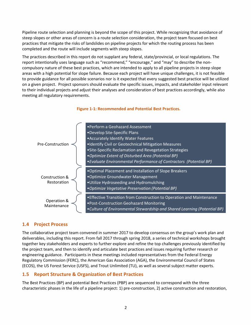
1.5 Report Structure & Organization of Best Practices The Best Practices (BP) and potential Best Practices (PBP) are sequenced to correspond with the three characteristic phases in the life of a pipeline project: 1) pre-construction, 2) active construction and restoration,
Pre-Construction
•Perform a Geohazard Assessment •Develop Site-Specific Plans •Accurately Identify Water Features •Identify Civil or Geotechnical Mitigation Measures•Site-Specific Reclamation and Revegetation Strategies•Optimize Extent of Disturbed Area (Potential BP)•Evaluate Environmental Performance of Contractors (Potential BP)
Construction & Restoration
•Optimal Placement and Installation of Slope Breakers •Optimize Groundwater Management •Utilize Hydroseeding and Hydromulching •Optimize Vegetative Preservation (Potential BP)
Operation & Maintenance
•Effective Transition from Construction to Operation and Maintenance•Post-Construction Geohazard Monitoring •Culture of Environmental Stewardship and Shared Learning (Potential BP)
Figure 1-1: Recommended and Potential Best Practices.
3
and 3) operation and maintenance. For each phase, best practices were identified and organized using a similar structure as follows:
• Definition and Purpose: The BP is briefly defined and its purpose stated. • Planning Considerations: The key issues that should be raised and resolved to promote effective
implementation are identified. • Design Criteria: The key design elements that should be included when utilizing the BP are outlined. • References: Publicly available technical references used to formulate the BP are provided. The list
highlights key sources of information and is not intended to be comprehensive. Potential Best Practices (PBP) are actions that have the potential to become BPs but additional work is needed to fully develop these recommendations:
• Definition and Purpose: The PBP is briefly defined and its purpose stated. • Initial Considerations: Initial key design elements that should be considered are identified. • Interim Recommendations: Some initial key issues that should be raised and resolved to promote effective
implementation are identified. • Questions: Steps or options needed to formulate the BPs are discussed.
In all, this report contains 10 recommended BPs, along with four PBPs that hold promise but need further work and analysis to become recommended practices (Figure 1-1).
1.6 Limitations It is understood that each project is unique and project sponsors are encouraged to consult with their pipeline construction contractors regarding the installation and maintenance of preventive measures.
4
2 PRE-CONSTRUCTION PHASE 2.1 BEST PRACTICES
2.1.1 Perform a Geohazard Assessment to Identify High-Hazard Landslide/Erosion Areas
Definition: Create an accurate indication of the presence of high landslide/erosion potential and erosion-prone slopes/areas utilizing desktop and site-survey methods.
Purpose: To reduce the probability of landslides or severe erosion through early and accurate discovery of high hazard areas and incorporation of findings into construction and restoration planning.
Planning Considerations:
1. Initiate this assessment as early in the process as possible to inform pre-construction planning.
2. Engage a qualified individual or team, such as a Professional Engineer, Professional Geologist, or equivalent qualification with relevant experience in geo-hazard assessments.
3. Solicit information from applicable state and federal resources (e.g. state or provincial geologists, U.S. or Canadian Geological Survey, land management agency experts) regarding historical landslide areas and unstable slopes.
4. Include in the assessment risk features outside of the Limits of Disturbance (LOD) that may contribute to landslide/erosion activity.
Design Criteria:
1. Evaluate landslide/erosion potential through a desktop review of state, provincial, and national resources, as well as project-specific LiDAR-generated topography or other high-resolution terrain data including, but not limited to, a review of the following:
a. previous and existing landslide-prone areas within the study corridor identified through state, provincial, and national landslide-mapping resources
b. topography, including hill-shading or digital terrain modeling c. geology, including mapped faults, state of stress, and area seismicity d. soils e. surface hydrography and groundwater discharge (seeps and springs)
2. Field-verify high-hazard landslide/erosion potential areas via site visits and surveys, and inspect for potential landslide triggers (e.g., coal seam outcrops, bedrock outcrops, and attitude (strike and dip) relative to slope orientation, bedrock jointing and faults, steep slopes, soils/bedrock interface susceptible to landslides, colluvial soils, natural drainage channels, erosion rills, seeps, wetlands).
3. Utilize the geohazard assessment to assign aggregated landslide/erosion-potential categories (e.g., low, medium, high) within the study corridor. Tailor these categories to reflect the pipeline operator’s assessment of landslide risk and associated environmental and pipeline integrity issues.
4. Determine aggregated landslide/erosion potential categories (typically medium and high) that require additional assessment (e.g., subsurface investigations, monitoring, software-driven slope stability assessment) to decide if civil/geotechnical measures are needed to stabilize the slope (as outlined in Best Practice 2.1.4 Identify Where Civil or Geotechnical Measures are Needed to Mitigate Slope Movement).
5. Incorporate findings into pre-construction planning.
5
a. See BPs 2.1.2, Develop Site-Specific Plans for High Landslide Potential and Erosion-Prone Slopes; 2.1.3, Accurately Identify Water Features Prior to Construction; and 2.1.4, Identify Locations Where Civil or Geotechnical Mitigation Measures are Needed to Minimize Slope Movement for dependent actions.
References:
1. American Association of State Geologists. n.d. State Geological Surveys. Alaska Division of Geological & Geophysical Surveys. http://www.stategeologists.org/surveys.php
2. Baum, R.L., Galloway, D.L. and Harp, E.L., 2008, Landslide and Land Subsidence Hazards to Pipelines: U.S. Geological Survey (USGS) Open-File Report 2008-1164. pubs.usgs.gov/of/2008/1164/
3. Bobrowsky, P.T. and Dominguez, M.J. 2012. “Landslide Susceptibility Map of Canada.” Geological Survey of Canada (GSC) Open File Report 7228. //doi.org/10.4095/291902
4. D.G. Honegger Consulting. 2009. “Guidelines for Constructing Natural Gas and Liquid Hydrocarbon Pipelines through Areas Prone to Landslide and Subsidence Hazards.” Pipeline Research Council International (PRCI). trid.trb.org/view/1477554
5. Federal Energy Regulatory Commission (FERC). 2017. “Guidance Manual for Environmental Report Preparation for Applications Filed Under the Natural Gas Act.” Section 4.6.4.1 Landslides
6. Godt, J., 1997, “Digital Compilation of Landslide Overview Map of the Conterminous United States” by Radbruch-Hall, D.H., Colton, R.B,. Davies, W.E., Lucchitta, I., Skipp, B.A. and Varnes, D.J., U.S. Geological Survey Open-File Report 97-289. landslides.usgs.gov/hazards/nationalmap/
7. Highland, L.M., and Bobrowsky, P. 2008. “The Landslide Handbook—a Guide to Understanding Landslides” Reston, VA, U.S. Geological Survey Circular 1325, 129 p.
8. Golder Associates, Inc. 2016. “Mitigation of Land Movement in Steep and Rugged Terrain for Pipeline Projects: Lessons Learned from Constructing Pipelines in West Virginia.” Final Report No. 2015-03. Interstate National Gas Association of America (INGAA) Foundation. www.ingaa.org/File.aspx?id=28629
9. Jackson, L.E. Jr., Bobrowsky, P.T. and Bichler, A., 2012, Canadian Technical Guidelines and Best Practices related to Landslides: A National Initiative for Loss Reduction”, Natural Resources Canada, Geological Survey of Canada (GSC) Open File Report 7059. doi.org/10.4095/292122
10. Spiker, E.C., and Gori, P., 2003. “National Landslide Hazards Mitigation Strategy: a framework for loss reduction.” Reston, VA. U.S. Geological Survey (USGS) Circular 1244.
6
2.1.2 Develop Site-Specific Plans for High Landslide Potential and Erosion-Prone Slopes
Definition: Conduct pre-construction planning for hazard avoidance, risk control measures, and specification of resources needed to implement controls as planned and to respond effectively to contingencies during construction.
Purpose: To identify effective control measures; ensure that appropriate resources are on site to implement control measures as designed; monitor efficacy of measures implemented; and address contingencies encountered during construction.
Planning Considerations:
1. Compose multidisciplinary teams of experienced technical experts – including regulatory agencies where appropriate – as a key part of ensuring well-developed plans.
2. Ensure that personnel responsible for documenting and amending risk control measures are familiar with the details and purpose of the site-specific plan for each high landslide hazard area.
3. Have construction crews with relevant experience execute (or manage) construction activities within a high-hazard area, whenever practicable.
4. Optimize operational safety, constructability, and environmental performance measures.
5. Maximize strategic timing of construction and final restoration activities:
a. Require excavation, installation, and restoration to be conducted as time-efficiently as possible to reduce the period during which the site is exposed to weather events.
b. Consider scheduling construction in high-hazard areas to avoid seasons when landslide hazard is highest.
c. Coordinate construction timing with the overall project schedule to minimize post-stabilization disturbance.
Design Criteria:
1. Identify water features that can contribute to landslide potential (see 2.1.3, Accurately Identify Water Features Prior to Construction).
2. Identify control measures to reduce landslide hazard potential:
a. Determine appropriate structural stabilization and erosion control measures (see 2.1.4, Identify Where Civil or Geotechnical Measures are Needed to Minimize Slope Movement).
b. Determine appropriate construction work areas (see 2.2.1, Potential Best Practice: Optimize Extent of Disturbed Area on High Landslide Potential Areas).
c. Determine appropriate vegetative control measures (see 2.1.5, Develop Site-Specific Reclamation and Revegetation Plans).
3. If post-construction geohazard monitoring will be needed, determine the monitoring method to be employed, and specify what equipment should be installed on or near the pipe during construction to record post-construction monitoring data. (see 4.1.2, Conduct Post-Construction Geohazard Monitoring).
4. Specify resources needed on site:
a. Select qualified contractors with relevant experience (“hill crews” or “slope crews”) to implement site-specific construction plans (i.e. (see 2.2.2, Potential Best Practice: Evaluate Environmental Performance of Contractors).
7
b. Ensure that qualified personnel with relevant expertise are dedicated to each high-hazard construction area to document that control measures are being implemented as designed, and to make judgements regarding modifications needed to accomplish desired outcomes.
c. Specify a chain of command assigning responsibility and authority for determining when additional expertise or resources are needed to respond to contingencies encountered during construction.
References:
1. Atlantic Coast Pipeline and Dominion Energy. 2017. Implementation Plan. FERC Docket Nos. CP15-554-000, CP15-554-001, & CP15-555-000. Environmental Condition 51 Part B. pp 68-74. Accession Number: 20171018-5002.
2. Federal Energy Regulatory Commission (FERC). 2017. “Guidance Manual for Environmental Report Preparation for Applications Filed Under the Natural Gas Act.”
8
2.1.3 Accurately Identify Water Features Prior to Construction
Definition: Identify surface and subsurface hydrologic features and drainage routes during the project pre-construction phase through qualified technical personnel via on-site inspections, LiDAR-obtained topographic review, and/or other high-resolution methods.
Purpose: To avoid and minimize slope failures and slips caused by water features or soil saturation.
Planning Considerations:
1. Recognize that water features are a primary cause for landslide and erosion in high-hazard landslide/erosion areas.
2. Engage a qualified individual or team with relevant experience in hydrologic assessment.
3. Solicit information from all applicable state/provincial and national resources.
Design Criteria:
1. Gather and analyze preliminary information necessary to identify hydrologic resources, including, but not limited to, vegetation, topography, soils, geology, and surface hydrography and subsurface hydrology such as groundwater seeps and springs.
2. Verify preliminary assessment through field surveys and identify hydrologic features contributing to high landslide or erosion potential, including microtopography, and incorporate high landslide or erosion potential areas into a preliminary site-specific construction plan.
3. Incorporate findings into pre-construction planning (see 2.1.2, Develop Site-Specific Plans for High Landslide Potential and Erosion Prone Slopes).
4. Prior to construction, validate assessment and finalize site-specific construction plan through on-site inspection.
5. Create a structure to ensure consistency of institutional knowledge between design and construction phases of the project.
References:
1. Federal Energy Regulatory Commission (FERC). 2017. “Guidance Manual for Environmental Report Preparation for Applications Filed Under the Natural Gas Act.” Section 4.2.2 Surface Water Resources.
2. James A.L., Watson, D.G. and Hansen, W.F., 2007, “Using LiDAR data to map gullies and headwater streams under forest canopy: South Carolina, USA” CATENA, 71(1), pp. 132-144. doi.org/10.1016/j.catena.2006.10.010. Viewed May 18, 2018.
3. US Geologic Survey (USGS). National Hydrography Dataset. Available at nhd.usgs.gov/.
4. U.S. Fish & Wildlife Service (USFWS). National Wetlands Inventory. Available at www.fws.gov/wetlands/nwi/Overview.html.
9
2.1.4 Identify Locations Where Civil or Geotechnical Mitigation Measures are Needed to Minimize Slope Movement
Definition: Determine where mitigation or site-restoration measures above and beyond general standard construction and restoration practices (e.g., slope breaker installation, erosion control measures, seeding/vegetation, trench breakers) are necessary to stabilize disturbed slopes.
Purpose: Utilize civil/geotechnical measures to reduce the probability and mitigate the effects of landslides on pipeline ROW.
Planning Considerations:
1. Weigh options for geotechnical measures, which include (but are not limited to) ground armoring, special drainage measures, terracing, buttressing, rock fill, piling, and nailing.
2. Ensure that qualified personnel with relevant expertise (see Practice 2.1.1) conduct analyses and planning.
Design Criteria:
1. Evaluate whether the slope will remain unstable over the long term and/or if potential landslide-failure surfaces will be below the depth of any natural vegetation root reinforcement.
2. If so, implement civil/geotechnical measures. Consider the full suite of potential tools and techniques when determining appropriate mitigation measures (e.g., ground armoring, special drainage measures, terracing, buttressing, rock fill, piling, nailing) to stabilize the slope.
References:
1. Wang, Y.Y., West, D., Dewar, D., Hart, J., McKenzie-Johnson, A. and Sen, M., 2016, “Integrity Management of Ground Movement Hazards” Proceedings of the 11th International Pipeline Conference. Vol 1 2016 Paper No. IPC2016-64513, pp. V001T03A087. doi:10.1115/IPC2016-64513.
2. Bobrowsky, P.T. and Dominguez, M.J., 2012, “Landslide Susceptibility Map of Canada.” Geological Survey of Canada (GSC) Open File Report 7228. //doi.org/10.4095/291902
3. Godt, J., 1997, “Digital Compilation of Landslide Overview Map of the Conterminous United States” by Radbruch-Hall, D.H., Colton, R.B,. Davies, W.E., Lucchitta, I., Skipp, B.A. and Varnes, D.J., U.S. Geological Survey Open-File Report 97-289. landslides.usgs.gov/hazards/nationalmap/
4. Honegger D.G., Hart J.D., Phillips R., Popelar, C. and Gailing, R.W., 2010, “Recent PRCI Guidelines for Pipelines Exposed to Landslide and Ground Subsidence Hazards” Proceedings of the 8th International Pipeline Conference, Vol 2, Paper No. IPC2010-31311, pp. 71-80; 10 pages. doi:10.1115/IPC2010-31311
5. Golder Associates, Inc. 2016. “Mitigation of Land Movement in Steep and Rugged Terrain for Pipeline Projects: Lessons Learned from Constructing Pipelines in West Virginia.” Final Report No. 2015-03. Interstate National Gas Association of America (INGAA) Foundation. www.ingaa.org/File.aspx?id=28629
6. Halchak, B.E., Bell, J. and Dharmapuri, S., 2017. “Landslide Analysis Using Multi-Temporal LiDAR Data” LiDAR Magazine, 7 (3). www.lidarmag.com/content/view/12244/
7. D.G. Honegger Consulting. 2009. “Guidelines for Constructing Natural Gas and Liquid Hydrocarbon Pipelines through Areas Prone to Landslide and Subsidence Hazards.” Pipeline Research Council International (PRCI). trid.trb.org/view/1477554

10
8. US Geological Survey (USGS). n.d. Seismic Hazard Maps and Site-Specific Data. Available at earthquake.usgs.gov/hazards/hazmaps/
11
2.1.5 Develop Site-Specific Reclamation and Revegetation Strategies
Definition: Include reclamation strategies to stabilize high landslide potential and erosion-prone slopes, for both short and long terms, in site-specific plans.
Purpose: To reestablish soil health and promote immediate vegetative cover, root growth, and long-term reclamation success.
Planning Considerations:
1. Engage an agronomist, range scientist, or soil scientist to develop the reclamation plan and, if possible, to oversee restoration performance.
2. Use a qualified pipeline restoration specialist or contractor with relevant experience to implement or manage reclamation plans.
3. Minimize the permanently maintained ROW width where possible.
4. Utilize soil amendments to achieve successful vegetative establishment if topsoil is not segregated.
5. Recognize that time of year will affect establishment success (e.g., seed establishment may be reduced during hot, dry seasons, so tree and shrub planting should be performed during spring and fall).
6. Understand that successful revegetation is likely to extend beyond project construction.
7. Budget to include construction and longer-term post-construction operations to manage the restored vegetation in high landslide potential and erosion-prone areas.
8. Follow up after short-term restoration to ensure that the long-term maintenance plan will be implemented as designed once the project is transferred from the construction division to the operations division.
Design Criteria:
1. Develop individual draft reclamation strategies for each high landslide potential and erosion-prone area prior to construction.
2. Specify both short-term and long-term restoration performance measures within relevant contracts, and identify the parties responsible for compliance with these measures.
3. Obtain soil samples during construction to validate reclamation plan prior to implementation.
4. Evaluate soil health and enact restoration measures as needed for successful long-term revegetation, such as application of appropriate soil amendments and utilization of cover crops to replenish soil biota and nutrients.
5. Plan to replant with appropriate vegetation/seed mixture in accordance with any regulatory requirements:
a. Utilize native species that will match or complement the adjacent habitat.
b. Choose deep-rooted species over shallow-rooted species, when possible, to improve environmental performance and reduce the risk of slips over the long term.
12
c. Plant deeper-rooting shrub or small tree species in outer portions of LOD where they will not conflict with operational uses or regulatory requirements.
d. Encourage revegetation of pioneer species by installing bird wire, living slope breakers, etc.
References:
1. Elzinga, C.L., Salzer, D.W. and Willoughby J.W., 1998. “Measuring and Monitoring Plant Populations.” BLM Technical Reference 1730-1 Bureau of Land Management, National Business Center, Denver, Colorado. www.blm.gov/nstc/library/pdf/MeasAndMon.pdf
2. Federal Energy Regulatory Commission Office of Energy Project (FERC-OEP), 2013, “Upland Erosion Control, Revegetation, and Maintenance Plan, Chapter V. Restoration Section D. Revegetation”. www.ferc.gov/industries/gas/enviro/plan.pdf
3. Natural Resource Conservation Service (NRCS) and Ducks Unlimited. n.d. “Vegetating with Native Grasses in Northeastern North America”, U.S. Department of Agriculture, Washington, D.C. www.nrcs.usda.gov/Internet/FSE_PLANTMATERIALS/publications/nypmsbk10321.pdf
4. Sedivec, K., Piper, C., Printz, J., Wick, A., Daigh, A. and Limb, R., 2014. “Successful Reclamation of Lands Disturbed by Oil and Gas Development and Infrastructure Construction”, North Dakota State University Extension Service. Fargo, ND
5. U.S. Bureau of Land Management (BLM), 2007, “Surface Operating Standards and Guidelines for Oil and Gas Exploration and Development (Gold Book)”, BLM National Science and Technology Center Branch of Publishing Services. https://www.blm.gov/programs/energy-and-minerals/oil-and-gas/operations-and-production/the-gold-book
13
2.2 POTENTIAL BEST PRACTICES
2.2.1 Potential Best Practice: Optimize Extent of Disturbed Area on High Landslide Potential and Erosion-Prone Slopes
Definition: Design Limits of Disturbance (LOD) that balance operational safety, constructability, and environmental performance.
Purpose: To encourage thorough evaluation of the cleared area actually needed for efficient pipeline installation, safety, and preservation of vegetation to reduce landslide and erosion potential during and after pipeline construction.
Initial Considerations:
1. Determine LOD based on factors such as pipe diameter, contractor equipment, and proposed construction methods.
2. Be aware that segregating topsoil requires additional disturbed area.
3. Recognize that the type of landslide risk may dictate the extent to which LOD modification is feasible.
4. Consult with contractors who have steep slope construction experience during the design phase to help determine the most efficient work space width to meet safety, environmental, and cost constraints and to help develop an execution plan.
Interim Recommendations:
1. Design the LOD to optimize operational safety, constructability, environmental performance, and other measures.
Questions to Inform Development of Guidance for Optimizing LOD:
1. What are the cost, safety, and environmental tradeoffs of narrowing an LOD versus operating, restoring, and maintaining a wider LOD?
2. What technical guidance can be developed for reducing disturbed areas on steep slopes given safety and operational constraints?
2.2.2 Potential Best Practice: Evaluate Environmental Performance of Contractors
Definition: Follow a process for collecting and reporting successful environmental performance in high landslide hazard areas.
Purpose: To improve the ability of pipeline companies to select contractors with proven environmental performance to implement construction in high landslide hazard areas.
Initial Considerations:
1. Consult the Federal Energy Regulatory Commission (FERC) docket for a record of environmental performance.
2. Check for records of environmental performance maintained by state agencies.
3. Be aware that no standardized record of environmental performance currently exists.
4. Recognize that successful prevention/minimization of landslides requires special expertise.
14
Interim Recommendations:
1. Obtain a list of relevant projects from contractors and seek records indicating environmental performance.
2. Consider developing your own company process for measuring and tracking environmental performance based on FERC’s compliance definitions and those of other relevant oversight agencies until an effective industry-wide tracking system or program is implemented. (Afterwards, companies could select the best tracking system for their situations.)
3. Initiate further discussions with contractors to develop mechanisms for assessing their environmental performance.
Questions to Inform Future Development of Industry-Wide Tracking System
1. How can industry extend the management systems that have been successful in creating a culture of safety to create a culture of environmental stewardship?
2. What are the best environmental performance metrics that can be applied routinely and consistently?
3. What mechanism can industry use to track and facilitate evaluation of contractors’ environmental performance?
15
3 CONSTRUCTION AND RESTORATION PHASES 3.1 BEST PRACTICES
3.1.1 Ensure Optimal Placement and Installation of Slope Breakers
Definition: Design and install permanent slope breakers and drainage points as needed throughout the LOD, in addition to those directed by relevant regulating authority.
Purpose: To ensure that slope breakers are optimally spaced, placed, and installed to minimize erosion potential of surface water runoff, along with soil saturation that can contribute to landslides.
Planning Considerations:
1. Be aware that this practice does not supplant any federal, state/provincial, or local regulations.
2. Engage personnel with extensive field experience in the installation of slope breakers to oversee their location and construction.
3. Account for probable rain events in the project area and, in accordance with safety considerations, decrease spacing of slope breakers and other structural drainage solutions to accommodate longer return interval storm events where appropriate.
4. Consider the discharge location, along with the potential flow path.
5. Minimize potential for discharges from upslope slope breakers to concentrate flow.
6. Apply this practice to temporary slope breakers where practicable.
7. Review the FERC Docket for similar projects on which slope breakers were utilized successfully.
Design Criteria:
1. Spacing:
a. Evaluate site-specific slope conditions to ensure that slope breakers are installed at optimal points in the ROW to control surface water drainage (i.e., breaks in the slope).
b. Increase number of slope breakers above minimum requirements in response to site-specific conditions.
c. Consider best placement based on topography and location of discharge first, and then consider spacing requirements.
2. Placement:
a. Avoid positioning slope breakers where adjacent conditions will cause problems (e.g., where slope conditions at the discharge point will redirect water back toward the project area, or adversely impact property owners along the flow path).
b. Align slope breakers with sub-surface trench breakers to manage increased water flows within the trench; install drainage measures such as bleeder drains to mitigate the accumulation of water at these locations.
3. Construction:
a. Grade slope breakers to avoid low points, moderate runoff velocity, and minimize potential erosion.
16
b. Ensure that inspectors are appropriately trained and competent to evaluate proper placement and sloping of slope breakers.
c. Use technical measures to evaluate proper grading of slope breakers, including surveying, string lines, etc.
d. Disperse energy of water that is discharged off the slope breakers, using structures such as J-hook compost filter sock, rock channels along the side of ROW, or level spreaders.
4. Educate landowners on the need to keep water control measures in place, and consider including language to that effect in landowner agreements.
References:
1. Golder Associates, Inc. 2016. “Mitigation of Land Movement in Steep and Rugged Terrain for Pipeline Projects: Lessons Learned from Constructing Pipelines in West Virginia.” Final Report No. 2015-03. Interstate National Gas Association of America (INGAA) Foundation. www.ingaa.org/File.aspx?id=28629
2. Massachusetts Department of Environmental Protection (MassDEP), 2003, “Massachusetts Erosion and Sediment Control Guidelines for Urban and Suburban Areas, Water Bar”. prj.geosyntec.com/npsmanual/waterbar.aspx. Viewed 9 May 2018
3. Washington State Department of Ecology, in press, “2019 Stormwater Management Manual for Western Washington BMP C203: Water Bars”. Digital resource. fortress.wa.gov/ecy/madcap/wq/2019SWMMWWPrelimDraft/Content/Topics/VolumeII/ConstructionStormwaterBMPs/ConstructionRunoffBMPs/BMPc203.htm. Viewed 9 May 2018.
17
3.1.2 Optimize Groundwater Management During Construction and Restoration
Definition: Design and install measures to manage the exposure of groundwater (e.g., seeps, springs, water table) to disturbed areas during pipeline construction activities within the LOD.
Purpose: To ensure successful management of exposed groundwater and minimize seepage-related flow interference during construction and restoration, as well as potential for post-construction landslides.
Planning Considerations:
1. Be aware that mitigation measures may require water to be conveyed to an off-ROW location.
2. Consider in advance all discharge locations and downslope impacts.
3. Obtain landowner and agency approvals as needed for off-ROW disturbance, discharge outlets, etc.
4. Keep potentially necessary materials/supplies on or near site during construction for rapid deployment as needed.
5. Involve personnel with prior relevant experience in slope water management during implementation.
6. Consider probable rain events and/or wetter times of year, when elevated water tables and/or increased seepage would occur, and design mitigation measures for maximum flows rather than levels observed during construction.
7. Be aware that these measures are not intended to supplant any federal, state/provincial, or local regulations.
8. Develop a system for maintaining accurate records of season, soil character, site conditions, and weather for any groundwater encounters to inform future issue avoidance and adaptive management/avoidance.
9. Tailor actions to meet the site-specific requirements for each situation.
Design Criteria:
1. Implement rapid-response measures to clear the slope of groundwater seepage during construction.
a. If seepage is entering the disturbed ROW from off-ROW:
i. excavate a shallow trench along the LOD edge, line the trench with plastic sheeting to prevent sedimentation and erosion, and direct the flow back to an off-ROW vegetated stable area and/or through an energy-dissipating device.
ii. install a flume pipe at the source to convey the flow across LOD to an off-ROW vegetated stable area and/or through an energy-dissipating device. Remove and replace the flume pipe as needed.
b. If the source of seepage is clearly identified within LOD, use sandbags and plastic sheeting to pond the clean water at its source and funnel the water via a corrugated high-density polyethylene pipe to an off-ROW vegetated stable area and/or through an energy-dissipating device.
2. Implement permanent civil engineering measures during restoration:
a. Install subsurface drainage in trench and across ROW, including but not limited to French drains, curtain drains, bored or driven horizontal drains, and multi-flow and/or other geosynthetic products.
b. Replace surficial soils with stable, permeable erosion granular material and/or rip-rap rock products where needed.
c. Reinforce soil above drainage locations through geosynthetics, geogrids, and/or soil mesh/soil nailing.

18
d. Incorporate sufficiently sized drainage into trench breakers using granular fill or other means to handle maximum foreseeable flows.
References:
1. Federal Energy Regulatory Commission (FERC). 2017. “Guidance Manual for Environmental Report Preparation for Applications Filed Under the Natural Gas Act.” Section 4.2.1 Groundwater Resources.
2. US Geologic Survey (USGS). USGS Groundwater Data. Available at water.usgs.gov/ogw/data.html.
3. U.S. Fish & Wildlife Service (USFWS). National Wetlands Inventory. Available at www.fws.gov/wetlands/nwi/Overview.html.
19
3.1.3 Utilize Hydroseeding and Hydromulching for Vegetative Restoration
Definition: Apply a liquid mixture of seed, mulch, and soil amendments to a disturbed area to aid in erosion control and provide a seedbed conducive for revegetation success. Hydroseeding typically involves applying seed and mulch in a single slurry application, while hydromulching typically involves broadcasting seeds, followed by applying a liquid mulch slurry. The terms hydroseeding and Hydromulching are sometimes used interchangeably.
Purpose: To ensure appropriate seed-to-soil contact and provide soil surface protection against erosion.
Planning Considerations:
1. Conduct hydroseeding and hydromulching either through ground-based or aerial application methods; consider accessibility and terrain when determining the best application method.
2. Recognize that hydroseeding is best applied in humid climates with clay or clay-loam soils. The single application is easier and safer in difficult to access areas and provides a more even distribution over the width of the ROW.
3. Adjust hydromulch application rates in arid climates to meet site-specific soil and rainfall conditions.
4. Consider the following before applying hydroseed and/or hydromulch:
a. Highly Erodible Soils – soil conditions that are unsafe for standard construction equipment should be considered for aerial application of hydroseed and/or hydromulch.
b. Proximity to Sensitive Areas (e.g., cultural resources, bodies of water) – disturbance from standard construction equipment in areas that could lead to erosion and sedimentation that could impact these sensitive resources.
c. Rainfall Intensity – areas that receive high amounts of rainfall throughout the year need a stronger surface medium that can withstand rainfall impact better than standard crimped straw.
d. Water Flow Patterns – preferential flow patterns and channels can easily wash away standard crimped straw and sometimes hydromulched surfaces.
5. Conduct soil tests prior to applications to ensure proper types of hydromulch and soil amendments are used for that particular location.
Design Criteria:
1. Choose hydroseeds and hydromulches appropriate for the environment and slopes being considered, as there are numerous products available on the market geared toward different scenarios and conditions. Apply all hydroseed and hydromulch products according to manufacturers’ suggested rates.
2. Be aware that dry applied mulches can be used in place of hydromulches based on manufacturer labeled recommendations.
3. Apply seeds prior to the mulch slurry to ensure proper seed-to-soil contact. Seed placement can be performed by drilling, broadcasting, or hydroseeding prior to the hydromulch application.
4. Add soil amendments (fertilizer, lime, biostimulants, etc.) either prior to or during hydromulch application at prescribed rates based on prior soil tests. Note that all lime applications should be performed on calcium carbonate equivalents (CCE) to raise soil pH to proper levels.
References:

20
1. California Department of Transportation (Caltrans), 2017, “Hydroseed and Hydromulch”, Erosion Control Toolbox. www.dot.ca.gov/design/lap/landscape-design/erosion-control/hydroseed/hyrdroseed_hydromulch.html
2. US Department of Agriculture (USDA). Hydroseeding and Hydromulching fact sheet www.nrcs.usda.gov/wps/portal/nrcs/detail/wy/technical/?cid=nrcs142p2_027264
21
3.2 POTENTIAL BEST PRACTICE
3.2.1 Potential Best Practice: Optimize Vegetative Preservation
Definition: Protect existing vegetation, root systems, and biologically active zones during construction.
Purposes:
1. To reduce short- and long-term impacts of construction activities on work areas outside of the immediate trench area.
2. To minimize the accumulation of water caused by removal of vegetation in unstable soils.
3. To speed the recovery/stabilization of the existing forest after construction.
4. To maintain soil and bedrock shearing resistance through preservation of deep-reaching roots for plant species that will coppice sprout, or in situations where root decay will not create additional soil instabilities given the implemented reclamation plan.
Initial Considerations:
1. Be aware that this practice may not be feasible on extremely steep and/or extremely long slopes.
2. Consider constraints such as pipe diameter and safety concerns in evaluating the extent to which LOD can be reduced.
Interim Recommendations:
1. Where feasible, minimize root disturbance:
a. Flush-cut trees within LOD where grubbing is not required or an alternative to grubbing is practicable.
b. Root prune along edges of trench/grading area.
c. Protect flush-cut areas with geotextile fabric and cover with topsoil from over the trench and minimized work area.
d. Run equipment on top of protected flush-cut area during trenching, stringing, and pipe installation activities.
2. Restore topsoil from flush-cut area during final grading.
Questions to Inform Future Development:
1. What slope geometry conditions are preferable for this practice?
2. How can concerns regarding equipment stability from non-graded areas be addressed?
22
4 OPERATIONS AND MAINTENANCE PHASE 4.1 BEST PRACTICES
4.1.1 Ensure an Effective Transition from Construction to Operation and Maintenance
Definition: Provide for effective communication and implementation of post-construction goals and requirements for ongoing operation and maintenance (O&M).
Purpose: To ensure implementation of long-term restoration; integrate planned O&M actions; reduce landslide and sedimentation potential; and promote continuous improvement.
Planning Considerations:
1. Promote effective communication of institutional knowledge regarding environmental permitting, regulatory review, and post-construction plan implementation – or attempt to have consistent personnel responsible across project phases. Ideally, this practice would occur within both pipeline companies and permitting agencies.
2. Engage operations personnel at the appropriate project phase to plan for long-term restoration activities.
3. Ensure that contingency planning provides adequate resources for operations personnel to address unanticipated issues.
Design Criteria:
1. Ensure that operations personnel have a thorough understanding of what occurred on high landslide or erosion prone areas during construction:
a. Clearly delineate high-hazard areas in project records prior to the end of construction.
b. Communicate measures taken to mitigate high-hazard areas and anticipated maintenance of those measures.
c. Conduct on-site reviews of high-hazard areas with construction and operations personnel during project hand-off as practicable.
2. Implement post-construction restoration and project-specific compliance measures:
a. Ensure company and contractor post-construction measures are clearly specified and completed as scheduled.
b. Clarify needs and ensure adequate resources for activities to be undertaken by operations personnel.
References:
1. Association for Project Management, 2017, “How can we hand over projects better?”, APM Research Fund Series. www.apm.org.uk/resources/find-a-resource/project-handover/ Viewed 18 May 2018.
2. Federal Energy Regulatory Commission Office of Energy Project (FERC-OEP), 2013, “Upland Erosion Control, Revegetation, and Maintenance Plan, Chapter VII. Post-Construction Activities and Reporting”. www.ferc.gov/industries/gas/enviro/plan.pdf
23
4.1.2 Conduct Post-Construction Geohazard Monitoring
Definition: Monitor ground movements and potential impacts to pipeline integrity (i.e., Geohazard Monitoring). Ground movements may include landslides, seismic events and/or settlement/subsidence (caused by karst sinkholes, mining subsidence, or groundwater withdrawal).
Purpose: To monitor ground movement within the pipeline ROW to reduce hazard/threat to the pipeline and surrounding resources.
Planning Considerations:
1. Consider the main options for geohazard monitoring and inspection:
a. Aerial Methods: Perform aerial patrol monitoring (frequency can be adjusted to site conditions), aerial photo review and interpretation (aerial photographs can be used to review historical landslides over large areas), and LiDAR surveys (a repeatable aerial laser-based measurement system).
b. Satellite-Based Methods: Use InSAR (Interferometry Using Radar Imagery) to measure subsidence and, in some cases, landslides. Note that InSAR may be affected by vegetation growth in some regions.
c. Ground/Geotechnical Instrumentation: Consider options for using geotechnical monitoring instruments within the ROW: slope inclinometers, extensometers, piezometers (measures pore water pressure in the subsurface), seismographs (detects seismic waves generated by earthquakes and other sources, including induced seismicity), and ground-based InSAR systems.
d. GPS/Conventional Survey Methods: Engage geotechnical specialist to visit site and determine appropriate geodetic monitoring point locations and frequency. Have surveyor install geodetic monitoring points (rebar, pipe stakes, etc.) at selected locations, obtain baseline survey readings, and perform continuous survey readings at frequency established by geotechnical specialist. Surveyor routinely processes the survey data, and the geotechnical specialist reviews the data to determine appropriate response measures.
e. ROW Survey: Travel the pipeline ROW by foot to inspect for evidence of landslides or slips in addition to potential hazards already being monitored.
f. Pipe Monitoring Options:
i. Conduct depth-of-cover surveys to monitor ground movement from the ground surface.
ii. Apply strain gages/fiber-optic cables directly to the pipeline to monitor interactions between the pipeline and moving ground; conduct in-line inspection IMU surveys to monitor bending strain deformations across welds and run-to-run movement analysis.
iii. In-line inspection of axial strain to assess the accumulation of absolute longitudinal strains within a pipeline.
Design Criteria:
1. Ensure that an effective monitoring program is in place as early as possible to detect potential landslide or slip hazards.
2. Verify desktop remote-sensed observations subsequent to performing aerial, LiDAR, or InSAR surveys as needed.
24
3. If ground movement is confirmed, consider further geological and/or geotechnical investigation prior to mitigation.
References:
1. BGC Engineering Inc. (BGC), 2015, “Trans Mountain Pipeline ULC, Trans Mountain Expansion Project Seismic Hazard Update” www.google.com/url?sa=t&rct=j&q=&esrc=s&source=web&cd=2&cad=rja&uact=8&ved=0ahUKEwik26fTzpfbAhUM71MKHdWfCswQFggtMAE&url=https%3A%2F%2Fapps.neb-one.gc.ca%2FREGDOCS%2FFile%2FDownload%2F2748440&usg=AOvVaw3VVcCbE9LI_mQkfTyfD1DB. Viewed 18 May 2018
2. BGC Engineering Inc (BGC) 2017, Characterizing the Root Cause of Pipeline Failures from Geohazards. Letter report of November 17 to the Canadian Energy Pipeline Association. Transmountain Expansion Project, 2016. Seismic Program. www.transmountain.com/seismic-safety-measures.
3. Dewar, D., Tong, A. and McClarty, E. 2017. Assessing and Monitoring the Impacts of Very Slow Moving Deep-Seated Landslides on Pipelines. 70th Canadian Geotechnical Conference and the 12th Joint CGS/IAH-CNC Groundwater Conference. www.google.com/url?sa=t&rct=j&q=&esrc=s&source=web&cd=1&ved=0ahUKEwj90tXh0ZfbAhXL21MKHYLwBNMQFggtMAA&url=http%3A%2F%2Fwww.geoottawa2017.ca%2Fabstracts%2Fgeo2017160.docx&usg=AOvVaw2fhwMz9YRiSDNOXJzpZKV2
4. Nyman, D.J., Lee, E.M. and Audibert, J.M.E., 2008, “Mitigating Geohazards for International Pipeline Projects: Challenges and Lessons Learned” Proceedings of the 7th International Pipeline Conference. Vol 3, Paper No. IPC2008-64405, pp. 639-648. doi:10.1115/IPC2008-64405
5. Rizkalla, Moness. 2008. Pipeline Geo-Environmental Design and Geohazard Management, American Society of Mechanical Engineers (ASME), New York, NY dx.doi.org/10.1115/1.802816.
6. Wang, Y.Y., West, D., Dewar, D., Hart, J., McKenzie-Johnson, A. and Sen, M., 2016, “Integrity Management of Ground Movement Hazards” Proceedings of the 11th International Pipeline Conference, Vol 1, Paper No. IPC2016-64513, pp. V001T03A087. doi:10.1115/IPC2016-64513.
7. Young, A. and Lockey A., 2013, “The Assessment of Pipeline Integrity in Geohazard Areas Using ILI Data”, Proceedings of the ASME 2013 International Pipeline Geotechnical Conference, Paper No. IPG2013-1971, pp. V001T02A008. doi:10.1115/IPG2013-1971
25
4.2 POTENTIAL BEST PRACTICE
4.2.1 Potential Best Practice: Create a Culture of Environmental Stewardship and Shared Learning
Definition: Encourage processes for promoting environmental stewardship and sharing lessons learned regarding the effectiveness of landslide hazard reduction efforts.
Purpose: To advance the ability of pipeline companies to improve environmental performance in high landslide hazard landslide/erosion areas.
Initial Considerations:
1. Incorporate environmental messages similar to “safety minutes” into routine meetings and communications.
2. Establish authority and appropriate triggers to stop work for environmental hazards.
3. Collaborate with academics, NGOs, regulatory agencies, and other industry partners to evaluate and improve best practices and to analyze cost-benefit of employing best practices.
4. Establish research and development programs that leverage industry, academia, and other independent experts to develop better understandings of slope failures and techniques for prevention/mitigation.
Interim Recommendations:
1. Capture and share lessons learned internally.
2. Create opportunities for industry-wide dialogue and collaboration.
Questions to Inform Future Development
1. How can the industry measure the extent to which investments in enhanced environmental protection during the planning and construction phase reduce costs during the operations and maintenance phase?
2. How can industry create ongoing outlets for sharing lessons learned across multiple pipeline companies and industries?
3. How can industry and stakeholders create a “no-blame zone” where successes and failures can be examined to promulgate cost-effective and environmentally protective practices?
4. What mechanisms can facilitate investment in R&D to develop new best practices for ROW management on steep slopes?
26
5 GLOSSARY OF KEY TERMS Hydrography - the science of the measurement, description, and mapping of the surface waters of the earth, with special reference to their use for navigation. Hydrology - the science concerned with the properties of the earth's water, especially its movement in relation to land. Interferometric Synthetic Aperture Radar (InSAR) – a high-precision remote sensing technique that uses two or more synthetic aperture radar (SAR) images to generate maps of surface deformation or digital elevation, using differences in the phase of the waves returning to the satellite or aircraft. Light Detection and Ranging (LiDAR) - A distance sensing technology that measures distance to a target by illuminating the target with pulsed laser light and measuring the reflected pulses with a sensor. Differences in laser return times and wavelengths are used to make digital 3-D representations of the target that identify surface contours. Limits of Disturbance (LOD) or Limits of Clearance (LOC) - The area which may be disturbed as work is performed. No work may occur outside the limits of disturbance shown on an approved plan. Microtopography - The surface features of an area on a small scale that can affect runoff generation, surface/subsurface flow interactions, or subsurface flow patterns in hydrological systems. Right-of-Way (ROW) - A strip of land acquired for the construction and operation of a pipeline or some other facility; it may be owned outright or an easement taken for a specific purpose. Significant Landslide Potential and Erosion Prone Slopes - Areas that have a landslide susceptibility or incidence rating greater than “low” on the Landslide Overview Map of the Conterminous United States and/or a landslide susceptibility rating greater than “cold (dark green)” on the Landslide Susceptibility Map of Canada.
6 ENDNOTES [1] Bobrowsky, P.T. and Dominguez, M.J. 2012. “Landslide Susceptibility Map of Canada.” Geological Survey of
Canada (GSC) Open File Report 7228. //doi.org/10.4095/291902.
[2] Chaplin, S.J., Gerrard, R.A., Watson, J.M., Master, L.L. and Flack, S.R. 2000. “The Geography of Imperilment” in Stein, B.A., Kutner, L.S. and Adams, J.S.; eds. Precious Heritage, the Status of Biodiversity in the United States. Oxford University Press. New York.
[3] ICF International. 2016. “North American Midstream Infrastructure Through 2035: Leaning into the Headwinds.” Prepared for the Interstate Natural Gas Association of America (INGAA). www.ingaa.org/Foundation/Foundation-Reports/27958.aspx. Viewed 18 May 2018
[4] Pipeline and Gas Journal. 2017. “2017 Worldwide Pipeline Construction Report.” Pipeline and Gas Journal, vol. 244, No. 1. pgjonline.com/magazine/2017/january-2017-vol-244-no-1/features/pgj-s-2017-worldwide-pipeline-construction-report. Viewed 18 May 2018.
[5] US Department of Energy (DOE). 2015. “Natural Gas Infrastructure Implications of Increased Demand from the Electric Power Sector.”www.energy.gov/sites/prod/files/2015/04/f22/QER%20Analysis%20-%20Natural%20Gas%20Infrastructure%20Implications%20of%20Increased%20Demand%20from%20the%20Electric%20Sector.pdf. Viewed 18 May 2018.
[6] US Geological Survey (USGS). n.d. “Can major landslides and debris flows happen in all areas of the U.S.?”. Viewed 18 May 2018.
[7] US Geological Survey (USGS). n.d. “Landslides 101” landslides.usgs.gov/learn/ls101.php. Viewed 18 May 2018. USGS Landslide Hazards Program. landslides.usgs.gov/