Embed Size (px)
Citation preview
IMPROVING THE BUILT ENVIRONMENT
Smart Vapor BarrierCertainTeed DryRight ndash vs ndash Kraft-Faced Insulation
Objective As a follow on to an evaluation of the MemBrain vapor retarder system in a CARB home built by
Veridian Homes in Wisconsin CertainTeed wanted to compare the hygrothermal performances
of DryRighttrade fiberglass batts and kraft-faced fiberglass batts in a south facing wall assembly
with a moisture storage cladding material DryRight is batt insulation faced with MemBrainreg
the ldquosmartrdquo vapor retarder MemBrain changes its ability to resist the flow of water vapor
depending on the conditions within the construction assembly
Monitoring Overview Two adjacent bays in a second story south facing wall of a new modular home in Wilton CT
served as the field test section Conventional 2x4 framing is used and both bays are insulated
with CertainTeed R-21 fiberglass batts Bay No One uses CertainTeedrsquos DryRight system and
bay No Two uses kraft-faced batts Twelve Humirel temperaturerelative-humidity sensors (six
in each bay) have been strategically placed to track moisture movement in each bay Interior
walls are finished with conventional drywall The exterior wall is OSB over which Typar
HouseWrap a layer of 15 lb felt and fiber-cement siding was applied
Figure 1 South side with test bays indicated
Consor tium for A dvance d Re sidential Buil dings Steven Winter Associates Inc
wwwcarb-swaco m 50 Washington St 6th F l Norwalk CT 068 54 tel 203-857-0200 fax 203-857-0200 307 7th A ve Ste 1701 New York NY 10001 tel 212-564-5800 fax 212-741-8673 1112 16t h St N W St e 240 Wa sh ingt on D C 20036 tel 202-628-6100 fax 202-393-5043
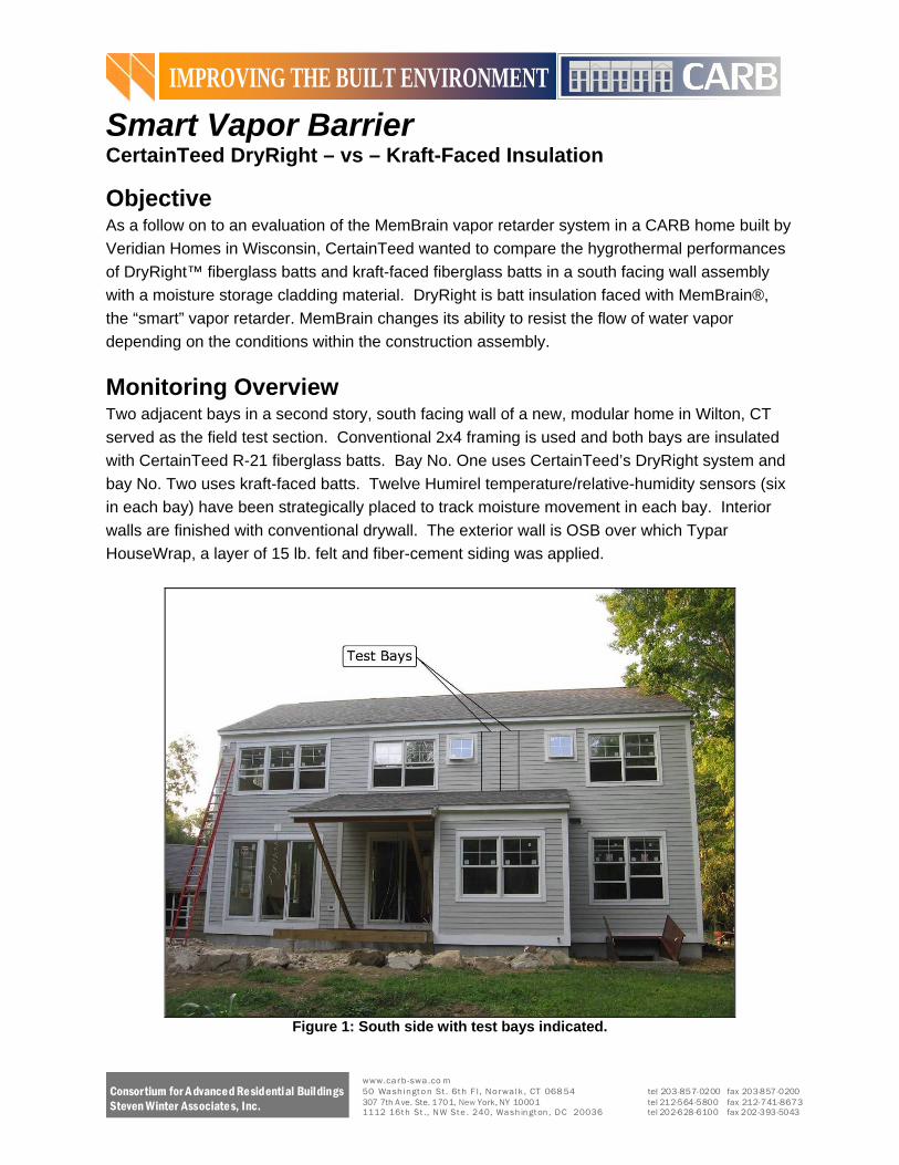
Figure 2 South side prior to installing fiber cement siding
Sensor Location and Installation The Humirel HTM2500 sensor was selected to measure temperature and relative humidity at
selected locations within the wall system The specifications of this sensor are
Testing range -40~85ordmC
Power Supply 5V 04 mA
Accuracy plusmn2 55 RH
Response Time 5 s
Output signal DC 1~4V for 0~100 RH
Six temperaturerelative-humidity sensors in each cavity are located as follows
Sensors 1 and 3 Between vapor barrier and insulation
Sensor 2 On interior side of exterior sheathing
Sensor 4 Between vapor barrier and drywall
Sensor 5 Inboard on bottom plate
Sensor 6 Outboard on bottom plate
Sensors 1 and 3 are friction fit between the fiberglass batt and its vapor barrier Care was taken to avoid unnecessary air gaps in fiberglass batt during installation
Figure 3 Installation of sensors 1 and 3
Consortium for A dvanced Re sidential Buildings Steven Winter Associate s Inc
wwwcarb-swaco m 50 Washington St 6th F l Norwalk CT 068 54 tel 203-857-0200 fax 203-857-0200 307 7th A ve Ste 1701 New York NY 10001 tel 212-564-5800 fax 212-741-8673 1112 16t h St N W St e 240 Wa sh in gt on D C 20036 tel 202-628-6100 fax 202-393-5043
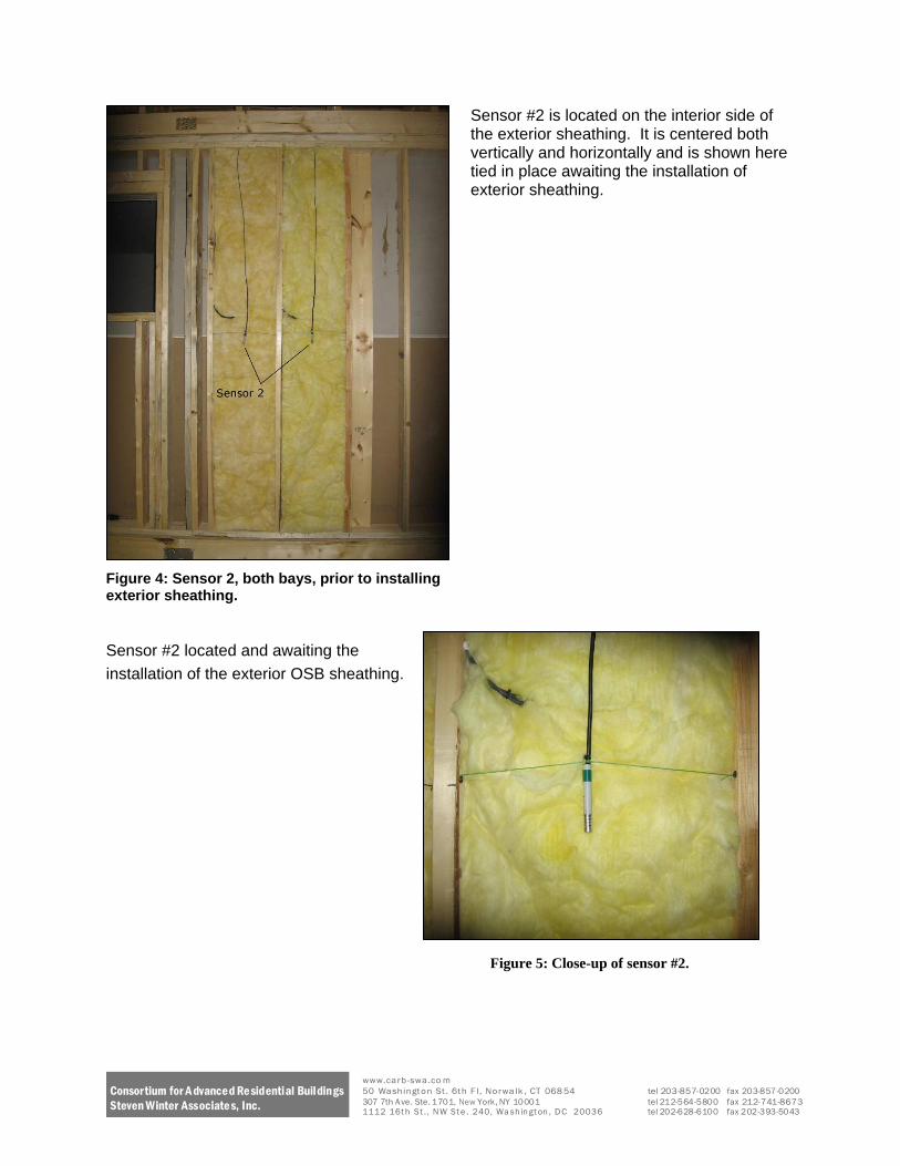
Sensor 2 is located on the interior side of the exterior sheathing It is centered both vertically and horizontally and is shown here tied in place awaiting the installation of exterior sheathing
Figure 4 Sensor 2 both bays prior to installing exterior sheathing
Sensor 2 located and awaiting the
installation of the exterior OSB sheathing
Figure 5 Close-up of sensor 2
Consortium for A dvanced Re sidential Buildings Steven Winter Associate s Inc
wwwcarb-swaco m 50 Washington St 6th F l Norwalk CT 068 54 tel 203-857-0200 fax 203-857-0200 307 7th A ve Ste 1701 New York NY 10001 tel 212-564-5800 fax 212-741-8673 1112 16t h St N W St e 240 Wa sh in gt on D C 20036 tel 202-628-6100 fax 202-393-5043
Sensor 4 located between the insulationrsquos
vapor barrier and the drywall are secured
with metal tape
Figure 6 Empty cavity showing location of sensors 4-6
Sensors 5 and 6 located outboard and inboard respectively on the bottom plate are secured
with silicone and metal clip
Figure 7 Close-up of sensors 5 and 6
Figure 8 Close-up of sensor 4
Consortium for A dvanced Re sidential Buildings Steven Winter Associate s Inc
wwwcarb-swaco m 50 Washington St 6th F l Norwalk CT 068 54 tel 203-857-0200 fax 203-857-0200 307 7th A ve Ste 1701 New York NY 10001 tel 212-564-5800 fax 212-741-8673 1112 16t h St N W St e 240 Wa sh in gt on D C 20036 tel 202-628-6100 fax 202-393-5043
In order to measure the indoor temperature and relative humidity a less intrusive HOBO U12
logger was placed inside to monitor and record conditions during the test period
Testing range -20~70ordmC
Accuracy plusmn 035degC from 0deg to 50degC plusmn25 from 10 to 90 RH
Outdoor weather conditions were monitored using the same Humirel temperaturerelativeshy
humidity sensor that is used in the wall cavities For exterior use it was mounted in an R M
Young radiation shield and mounted on the upper east corner of the homersquos south-facing side
Figure 9 Exterior TempRH Sensor housed in radiation shield
To measure the amount of sunlight available on a given day (sunny versus overcast) a Li-Cor
LI-200SA pyranometer was installed on the ridge cap of the home The pyranometer is not
tilted The specifications of the pyranometer are
Error lt5
Sensitivity 90 μA 1000Wm-2
Response time 10 μS
Operation Temperature -40~65 ordmC
Operation Relative humidity 0~100
Figure 10 Pyranometer on ridge cap
Consortium for A dvanced Re sidential Buildings Steven Winter Associate s Inc
wwwcarb-swaco m 50 Washington St 6th F l Norwalk CT 068 54 tel 203-857-0200 fax 203-857-0200 307 7th A ve Ste 1701 New York NY 10001 tel 212-564-5800 fax 212-741-8673 1112 16t h St N W St e 240 Wa sh in gt on D C 20036 tel 202-628-6100 fax 202-393-5043
Figure 11 Wall section drawing
Testing Methodology In order to compare the moisture performance of CertainTeed Dry Right with kraft-paper an
identical surface wetting condition is required as the initial condition to start the test This
condition was manually generated by spraying the outside surface on a sunny day so as to
stimulate a solar-driven moisture incursion
Data was collected for nearly two months The monitoring period can be summarized in three
different stages
1 Initial manual surface wetting with solar-driven moisture incursion (Aug 26th 2008 to
Sep 5th 2008)
2 Natural tropical storm (Sep 6th 2008 to Sep 25th 2008)
3 Rainy days (Sep 26th 2008 to Oct 13th 2008)
The detailed outdoor weather conditions are listed in the following tables
Consortium for A dvanced Re sidential Buildings Steven Winter Associate s Inc
wwwcarb-swaco m 50 Washington St 6th F l Norwalk CT 068 54 tel 203-857-0200 fax 203-857-0200 307 7th A ve Ste 1701 New York NY 10001 tel 212-564-5800 fax 212-741-8673 1112 16t h St N W St e 240 Wa sh in gt on D C 20036 tel 202-628-6100 fax 202-393-5043
Table 1 Stage 1 - Initial Manual Wetting
Date Weather Day time Max T
(degF) Day time
average RH Wetting Method
26-Aug FairSunny 708 40 Sprinkler -
Manual 27-Aug FairCloudy 679 52
28-Aug Cloudy 700 57
29-Aug Cloudy 688 69
30-Aug Cloudy 657 79
31-Aug Fair 738 51
1-Sep Fair 721 54
2-Sep Fair 766 56
3-Sep Partly Cloudy 747 67
4-Sep Fair 798 60
5-Sep FairPartly Cloudy 790 64
Table 2 Stage 2 - Natural Wetting by Wind-Driven Rain (Tropical Storm)
Date Weather Day time Max T (degF) Day time
average RH Wetting Method
6-Sep Rain (Tropical
Storm) 759 88 Wind-driven Rain
7-Sep RainFair 725 60 Wind-driven Rain
8-Sep Fair 702 56
9-Sep Rain 674 89 Wind-driven Rain
10-Sep Fair 636 57
11-Sep Cloudy 630 67
12-Sep CloudyRain 638 80
13-Sep Cloudy 711 81
14-Sep Cloudy 782 84
15-Sep Cloudy 766 52
16-Sep Cloudy 626 75
17-Sep Fair 633 66
18-Sep Fair 638 61
19-Sep Fair 567 61
20-Sep Fair 578 66
21-Sep Fair 658 65
22-Sep Partly Cloudy 633 73
23-Sep Fair 606 64
24-Sep Fair 607 71
25-Sep Cloudy 566 71
Consortium for A dvanced Re sidential Buildings Steven Winter Associate s Inc
wwwcarb-swaco m 50 Washington St 6th F l Norwalk CT 068 54 tel 203-857-0200 fax 203-857-0200 307 7th A ve Ste 1701 New York NY 10001 tel 212-564-5800 fax 212-741-8673 1112 16t h St N W St e 240 Wa sh in gt on D C 20036 tel 202-628-6100 fax 202-393-5043
Table 3 Stage 3-Natural wetting by rain
Date Weather Day time Max T
(degF) Day time
average RH Wetting Method
26-Sep Heavy Rain 602 99 Rain
27-Sep Light Rain 649 99 Rain
28-Sep Light Rain 693 91 Rain
29-Sep Cloudy 658 78
30-Sep Cloudy 628 76
1-Oct Mostly Cloudy 652 73
2-Oct Cloudy 553 65
3-Oct Cloudy 538 66
4-Oct Sunny 513 67
5-Oct Light Rain 513 96 Rain
6-Oct Cloudy 523 71
7-Oct Sunny 508 55
8-Oct Partly Cloudy 548 62
9-Oct Partly Cloudy 662 77
10-Oct Sunny 609 56
11-Oct Sunny 586 62
12-Oct Sunny 588 64
13-Oct Cloudy 614 75
Prior to the field test a laboratory test was performed to determine how to evaluate the
uniformity of moisture (water) content on the wall assemblyrsquos fiber-cement siding The
procedure was as follows
1 Calibrate the moisture content meter A moisture content meter (Delmhorst BD-2100)
was used to measure the uniformity of the moisture content on the exterior siding after
wetting and the average moisture content on the siding A sample of fiber-cement
siding collected from the field site (Specimen A) was placed in a water bath A digital
weight scale was used to measure the weight change of the specimen A It showed after
soaking for approximately two and a half days specimen A had reached equilibrium its
weight was not changing A saturated weight (equivalent to 100 moisture content) was
recorded Then specimen A endured a drying process so as to calibrate the moisture
content meter Specimen A was exposed to normal indoor air conditions for a certain
time then it was put in a sealed can for moisture re-distribution for at least a couple of
days (so as to eliminate the moisture gradient within the specimen) then the moisture
content meter was used to measure the moisture content as it dries Finally specimen A
was put in an oven for a 24-hr period at 212ordmF which would produce the absolute ldquodryrdquo
base weight for specimen A This base weight could be used to compute the real
Consortium for A dvanced Re sidential Buildings Steven Winter Associate s Inc
wwwcarb-swaco m 50 Washington St 6th F l Norwalk CT 068 54 tel 203-857-0200 fax 203-857-0200 307 7th A ve Ste 1701 New York NY 10001 tel 212-564-5800 fax 212-741-8673 1112 16t h St N W St e 240 Wa sh in gt on D C 20036 tel 202-628-6100 fax 202-393-5043
moisture content (RMC) for the specimen and then it could be used to generate the
calibration curve so as to translate the reading into real moisture content This would be
used to determine the initial moisture content at the start of the field test The result for
the calibration is summarized in Table 4
Table 4 Moisture Meter Calibration - drying process for the soaked specimen
Specimen A Weight
(g) Procedure Time
Moisture content
RMC Delmhorst
Wetting 674 Soaking 25 days 0212 100 988
Drying 640 Drying 1 day 0151 71 825
635 Drying 1 day 0142 67 820
602 Drying 1day 0083 39 783
595 Drying 1 day 0070 33 736
585 Drying 1 day 0052 25 533
576 Drying 4 day 0036 17 451
571 Drying 4 day 0027 13 366
Oven Drying 556 Drying 1 day 00 0
2 Determine the length of time for the initial water-spray wetting A wetting process was performed on another specimen (Specimen B) Before the wetting test specimen B (from equilibrium with normal indoor condition) had been dried in an oven to record its ldquodryrdquo base then a water spray was applied to track its weight change with time as shown in Table 5 It is estimated that after about 90 minutes spray the siding would reach about 80 moisture content
Table 5 Wetting process for the specimen
Specimen B Weight (g) Procedure Time Moisture content
RMC Delmhorst
Oven Drying 329 Drying 1 day 00 0
Wetting 366 Spraying 21 minutes 0112
371 Spraying 40 minutes 0128
379 Spraying 65 minutes 0152
385 Spraying 90 minutes 0170 80 835
The field test was initiated at noon on Aug 26th 2008 a sunny day The siding of the test wall sections was sprayed to simulate a ldquowind-driven-rainrdquo effect The spraying time was about 105 minutes
In order to ensure that the fiber cement siding was uniformly wet the Delmhorst hand-held moisture content meter was used Overall there are 12 pieces of siding from the top to the bottom of the test wall assemblies which have been assigned Siding 1 (on the top) to Siding 12 (on the bottom) The test section is about 75 feet wide which was evenly divided into 3 zones
Consortium for A dvanced Re sidential Buildings Steven Winter Associate s Inc
wwwcarb-swaco m 50 Washington St 6th F l Norwalk CT 068 54 tel 203-857-0200 fax 203-857-0200 307 7th A ve Ste 1701 New York NY 10001 tel 212-564-5800 fax 212-741-8673 1112 16t h St N W St e 240 Wa sh in gt on D C 20036 tel 202-628-6100 fax 202-393-5043
A B and C The arrangement can be demonstrated in the following Fig 13 Uniformity measurements were taken immediately after the spray wetting and the results are depicted in Fig 15 Good moisture content uniformity for the fiber cement siding was found across the test area with an average reading of 814 (Delmhorst Reading) which can be translated to about 60 soaked condition
Figure 12 Spray wetting of the siding outside the test bay
helliphelliphelliphelliphelliphellip
Siding 1
Siding 2
Siding 3
Siding 11
Siding 12
75 ft
Zone C Zone B Zone A
Fig 13 The geometry arrangement for the siding
Consortium for A dvanced Re sidential Buildings Steven Winter Associate s Inc
wwwcarb-swaco m 50 Washington St 6th F l Norwalk CT 068 54 tel 203-857-0200 fax 203-857-0200 307 7th A ve Ste 1701 New York NY 10001 tel 212-564-5800 fax 212-741-8673 1112 16t h St N W St e 240 Wa sh in gt on D C 20036 tel 202-628-6100 fax 202-393-5043
Figure 14 Testing the uniformity on the siding outside the test bay
Siding 1
0 10
20
30
40
50 60
70
80
90
100
Siding 2
Siding 3
Siding 5
Siding 6
Siding 7
Siding 8
Siding 9
Siding 11
Siding 12 A B C
Siding 10 Siding 4
Figure 15 Uniformity test for the siding
Consortium for A dvanced Re sidential Buildings Steven Winter Associate s Inc
wwwcarb-swaco m 50 Washington St 6th F l Norwalk CT 068 54 tel 203-857-0200 fax 203-857-0200 307 7th A ve Ste 1701 New York NY 10001 tel 212-564-5800 fax 212-741-8673 1112 16t h St N W St e 240 Wa sh in gt on D C 20036 tel 202-628-6100 fax 202-393-5043
Testing Results and Analysis
Stage 1 - Manual wetting by water spray The outdoor and indoor air temperature and relative humidity during test stage 1 is shown in Fig 16 The daily high temperatures kept rising during this test period and the relative humidity usually swung from 50-90 daily which was good for the test For indoor conditions the temperature varied within the 68-78degF range and the relative humidity stayed below 65
90
85
80
75
70
65
60
55
50
Outdoor Temperature (degF) 45
Indoor Temperature (degF)
40
82608 1200 82808 1200 83008 1200 9108 1200 9308 1200 9508 1200
Temperature Conditions
100
90
80
70
dity
(
60
Rel
ativ
e H
umi
50
40
Outdoor RH (-) 30
Indoor RH
20
82608 1200 82808 1200 83008 1200 9108 1200 9308 1200 9508 1200
Relative Humidity Conditions
Figure 16 OutdoorIndoor air temperature and RH during testing stage 1
Air
Tem
pera
ture
(degF
)
Consortium for A dvanced Re sidential Buildings Steven Winter Associate s Inc
wwwcarb-swaco m 50 Washington St 6th F l Norwalk CT 068 54 tel 203-857-0200 fax 203-857-0200 307 7th A ve Ste 1701 New York NY 10001 tel 212-564-5800 fax 212-741-8673 1112 16t h St N W St e 240 Wa sh in gt on D C 20036 tel 202-628-6100 fax 202-393-5043
The relative humidity within the insulation of the test bay sections indicate that the insulation within CertainTeed MemBraintrade vapor retarder section was at a lower relative humidity compared to the kraft paper section as Figure 17 shows
1000 MemBrain Inside Insulation Cavity RH []
Kraft Inside Insulation Cavity RH []
900
800
700
600
500
400
82608 1200 82808 1200 83008 1200 9108 1200 9308 1200 9508 1200
Figure 17 Comparison for RH within insulation cavity during testing stage 1
There is another potential benefit from the CertainTeed MemBraintrade vapor retarderrsquos ability
to keep the wall assembly dry This can mean lower local moisture content for the building material that translates into a lower local air RH within the porous building material as shown in Fig 19 (the MemBrain bay has lower RH compared to the same position in the kraft bay) Higher moisture content will increase the thermal conductivity of porous building material which will result in higher local temperature which is shown in Fig 18 (compared to the MemBrain the kraft had higher local temperature on the corresponding position at any time)
Loc
al R
elat
ive
Hum
idty
[
wwwcarb-swaco m Consortium for A dvanced Residential Buildings 50 Washington St 6th F l Norwalk CT 068 54 tel 203-857-0200 fax 203-857-0200
307 7th A ve Ste 1701 New York NY 10001 tel 212-564-5800 fax 212-741-8673Steven Winter Associates Inc 1112 16t h St N W St e 240 Wa sh in gt on D C 20036 tel 202-628-6100 fax 202-393-5043
1100
1000
900
800
700
600
500
82608 1200
850
750
650
550
450
Loc
al R
elat
ive
Hum
idty
[
T
empe
ratu
re (
degF)
350
82608 1200
Membrain Insulation Cavity Exterior Side T [degF]
Membrain Inside Insulation Cavity T [degF]
Membrain Insulation Cavity Interior Side T [degF]
Kraft Insulation Cavity Exterior Side T [degF]
Kraft Inside Insulation Cavity T [degF]
Kraft Insulation Cavity Interior Side T [degF]
82608 1800 82708 000 82708 600 82708 1200 82708 1800 82808 000
Figure 18 Comparison of Temperatures within the test bays
Membrain Insulation Cavity Exterior Side RH []
Membrain Inside Insulation Cavity RH []
Membrain Insulation Cavity Interior Side RH []
Kraft Insulation Cavity Exterior Side RH []
Kraft Inside Insulation Cavity RH []
Kraft Insulation Cavity Interior Side RH []
82608 1800 82708 000 82708 600 82708 1200 82708 1800 82808 000
Figure 19 Comparison of Relative Humidity within the test bays
wwwcarb-swaco m Consortium for A dvanced Residential Buildings 50 Washington St 6th F l Norwalk CT 068 54 tel 203-857-0200 fax 203-857-0200
307 7th A ve Ste 1701 New York NY 10001 tel 212-564-5800 fax 212-741-8673Steven Winter Associates Inc 1112 16t h St N W St e 240 Wa sh in gt on D C 20036 tel 202-628-6100 fax 202-393-5043
It is of interest to focus on the early stage of the drying right after the wetting of each vapor retarder system As Figure 20 depicts in each of these systems it is clear that from morning until a couple of hours after the peak afternoon spike the outside of the sheathing has the potential to dry to both the relatively drier inside and outside of the house However while the MemBrain material allows moisture to diffuse from the insulation cavity to the inside in response to this potential (as the water vapor pressure is much higher than the indoor side sheathing the MemBrain allows the sheathing to dry out more rapidly than the kraft and does not result in any moisture build-up behind the vapor retarder ) Therefore both the outdoor sheathing and the insulation cavity can maintain a lower moisture level resulting in lower local vapor pressure compared to that of the kraft system
0550
Outdoor Vapor Pressure (Psi) 0500
Membrain Insulation Cavity Exterior Side Vapor Pressure[Psi] 0450 Membrain Vapor Pressure Inside Insulation [Psi]
Membrain Insulation Cavity Interior Side Vapor 0400
Pressure[Psi] Indoor Vapor Pressure (Psi)
0350
0300
0250
0200
0150
0100
82608 1200 82608 1800 82708 000 82708 600 82708 1200 82708 1800 82808 000
a MemBrain System 0550
Outdoor Vapor Pressure (Psi)
0500 Kraft Insulation Cavity Exterior Side Vapor Pressure[Psi]
Kraft Vapor Pressure Inside Insulation [Psi]
0450
Kraft Insulation Cavity Interior Side 0400 Vapor Pressure[Psi]
Indoor Vapor Pressure (Psi)
0350
0300
0250
0200
0150
0100
82608 1200 82608 1800 82708 000 82708 600 82708 1200 82708 1800 82808 000
b Kraft System Figure 20 Comparison of local vapor pressure for both vapor retarder systems
Vap
or P
ress
ure
(Psi
)
Vap
or P
ress
ure
(Psi
)
wwwcarb-swaco m Consortium for A dvanced Residential Buildings 50 Washington St 6th F l Norwalk CT 068 54 tel 203-857-0200 fax 203-857-0200
307 7th A ve Ste 1701 New York NY 10001 tel 212-564-5800 fax 212-741-8673 Steven Winter Associates Inc 1112 16t h St N W St e 240 Wa sh in gt on D C 20036 tel 202-628-6100 fax 202-393-5043
Stage 2 - Natural wetting by tropical storm A 2-day tropical storm began on September 6th with heavy rain Figure 21 shows the outdoor and indoor temperature and RH
9608 000 9908 1200 91308 000 91608 1200 92008 000 92308 1200
a Temperature
40
45
50
55
60
65
70
75
80
85
90
95 A
ir T
empe
ratu
re (
degF)
Outdoor Temperature (degF)
Indoor Temperature (degF)
100
90
80
70
60
50
Rel
ativ
e H
umid
ity (
Outdoor RH (-)
Indoor RH
40
30
9608 000 9908 1200 91308 000 91608 1200 92008 000 92308 1200
b RH Figure 21 OutdoorIndoor air temperature and RH during testing stage 2
Consortium for A dvanced Re sidential Buildings Steven Winter Associate s Inc
wwwcarb-swaco m 50 Washington St 6th F l Norwalk CT 068 54 tel 203-857-0200 fax 203-857-0200 307 7th A ve Ste 1701 New York NY 10001 tel 212-564-5800 fax 212-741-8673 1112 16t h St N W St e 240 Wa sh in gt on D C 20036 tel 202-628-6100 fax 202-393-5043
The results indicate that the MemBrain system did help keep the wall dryer especially for the insulation cavity within the wall assembly as shown in Figure 22
1000 Membrain Inside Insulation Cavity RH []
Kraft Inside Insulation Cavity RH []
900
800
700
600
500
400
9608 000 9908 000 91208 000 91508 000 91808 000 92108 000 92408 000
Figure 22 Local RH within insulation cavity during testing stage 2
Stage 3-Natural wetting by continuous rain Three continuous days of rain began on September 26th 2008 The test continued to evaluate the moisture performance for both vapor retarder systems under this condition Figure 23 shows the outdoor and indoor temperature and RH
Loc
al R
elat
ive
Hum
idty
[
wwwcarb-swaco m Consortium for A dvanced Residential Buildings 50 Washington St 6th F l Norwalk CT 068 54 tel 203-857-0200 fax 203-857-0200
307 7th A ve Ste 1701 New York NY 10001 tel 212-564-5800 fax 212-741-8673Steven Winter Associates Inc 1112 16t h St N W St e 240 Wa sh in gt on D C 20036 tel 202-628-6100 fax 202-393-5043
30
35
40
45
50
55
60
65
70
75
Air
Tem
pera
ture
(degF
)
Outdoor Temperature (degF)
Indoor Temperature (degF)
Rel
ativ
e H
umid
ity (
92608 000 92908 000 10208 000 10508 000 10808 000
a Temperature
100
90
80
70
60
50
Outdoor RH (-) 40 Indoor RH
30
92608 000 92908 000 10208 000 10508 000 10808 000
b RH Figure 23 OutdoorIndoor air temperature and RH during testing stage 3
Consortium for A dvanced Re sidential Buildings Steven Winter Associate s Inc
wwwcarb-swaco m 50 Washington St 6th F l Norwalk CT 068 54 tel 203-857-0200 fax 203-857-0200 307 7th A ve Ste 1701 New York NY 10001 tel 212-564-5800 fax 212-741-8673 1112 16t h St N W St e 240 Wa sh in gt on D C 20036 tel 202-628-6100 fax 202-393-5043
Again the MemBrain system kept the wall at more favorable conditions as shown in Figure 24 In most instances the MemBrain system kept the insulation cavity well below 80 local RH and successfully reduced the number of hours the local RH gt80 (80 RH is a threshold that is adopted by ASHRAE to evaluate the potential danger of mold growth due to favorable air temperature and relative humidity) Relative humidity over 80 with air temperatures from 40~100degF for a continuous 30 day time span is suggested by the ASHRAE Handbook of Fundamentals to have the potential for mold growth (ASHRAE Handbook - Fundamentals 2005)
1000 Membrain Inside Insulation Cavity RH []
Kraft Inside Insulation Cavity RH []
900
800
700
600
500
400
92608 000 92908 000 10208 000 10508 000 10808 000
Figure 24 Local RH within insulation cavity during testing stage 3
It is noticeable in Figure 25 that in the early stage of the rain wetting the RH levels within the insulation cavity for both vapor retarder bays did not swing as sharply as usual because the ambient condition of rain showers with continuous high RH (gt95 for three days) The benefits of MemBrain are most apparent in this situation Since the ambient condition is wet the outdoor sheathing is wet and the only path to avoid moisture build-up is the penetration through the vapor retarder to indoor air allowing drying to the interior Figure 25 demonstrates this result showing that the vapor pressure at the outside sheathing and the insulation cavity of the MemBrain system is much lower than the kraft system This indicates that the MemBrain system will perform better in humid and rainy areas since it provides the ldquonarrow escaperdquo for moisture to the indoor side
Loc
al R
elat
ive
Hum
idty
[
wwwcarb-swaco m Consortium for A dvanced Residential Buildings 50 Washington St 6th F l Norwalk CT 068 54 tel 203-857-0200 fax 203-857-0200
307 7th A ve Ste 1701 New York NY 10001 tel 212-564-5800 fax 212-741-8673Steven Winter Associates Inc 1112 16t h St N W St e 240 Wa sh in gt on D C 20036 tel 202-628-6100 fax 202-393-5043
Consortium for A dvanced Re sidential Buildings Steven Winter Associate s Inc
0400
0350 V
apor
Pre
ssur
e (P
si)
Vap
or P
ress
ure
(Psi
) 0300
0250
0200
Outdoor Vapor Pressure (Psi)
Membrain Insulation Cavity Exterior Side Vapor Pressure[Psi] 0150 Membrain Vapor Pressure Inside Insulation [Psi]
Membrain Insulation Cavity Interior Side Vapor Pressure[Psi] Indoor Vapor Pressure (Psi)
0100
92808 000 92808 600 92808 1200 92808 1800 92908 000
a MemBrain System
0400
0350
0300
0250
0200 Outdoor Vapor Pressure (Psi)
Kraft Insulation Cavity Exterior Side Vapor Pressure[Psi]
Kraft Vapor Pressure Inside Insulation [Psi] 0150 Kraft Insulation Cavity Interior Side Vapor Pressure[Psi]
Indoor Vapor Pressure (Psi)
0100
92808 000 92808 600 92808 1200 92808 1800 92908 000
b Kraft System
Figure 25 Comparison of local vapor pressure for both vapor retarder systems
wwwcarb-swaco m 50 Washington St 6th F l Norwalk CT 068 54 tel 203-857-0200 fax 203-857-0200 307 7th A ve Ste 1701 New York NY 10001 tel 212-564-5800 fax 212-741-8673 1112 16t h St N W St e 240 Wa sh in gt on D C 20036 tel 202-628-6100 fax 202-393-5043
Conclusions A comparison field test was performed to evaluate the moisture performance of the CertainTeed DryRight system which uses the MemBrain vapor retarder versus conventional kraft-faced batts The results indicate that
1 The relative humidity within the insulation of the test bay with the MemBrain vapor retarder was lower than the test bay with kraft paper facing
2 When the ambient conditions are very wet for a relatively long time span (several rainy days) with significant wetting to cladding and sheathing assemblies the MemBrain system can provide a moisture escape path by its variable open-pore structure allowing higher levels of drying to the interior than does standard kraft-faced batts
For more information or comments contact Zhipeng Zhong at Zhongswintercom
Limits of Liability and Disclaimer of Warranty Steven Winter Associates Inc makes no representations about the suitability of this document for all situations The accuracy and completeness of the information provided by the author and the opinions stated herein are not guaranteed or warranted to produce any particular results and the advice and strategies contained herein may not be suitable for all applications This document is provided ldquoas isrdquo without express or implied warranty Steven Winter Associates Inc shall not be liable in any event for incidental or consequential damages in connection with or arising out of the furnishing performance or use of this documentation The information presented in this article is for use with care by professionals
Consortium for A dvanced Re sidential Buildings Steven Winter Associate s Inc
wwwcarb-swaco m 50 Washington St 6th F l Norwalk CT 068 54 tel 203-857-0200 fax 203-857-0200 307 7th A ve Ste 1701 New York NY 10001 tel 212-564-5800 fax 212-741-8673 1112 16t h St N W St e 240 Wa sh in gt on D C 20036 tel 202-628-6100 fax 202-393-5043
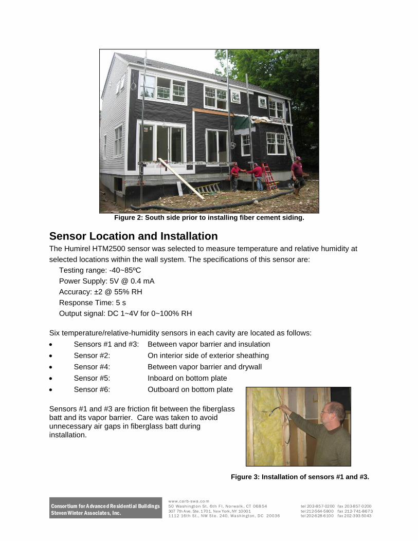
Figure 2 South side prior to installing fiber cement siding
Sensor Location and Installation The Humirel HTM2500 sensor was selected to measure temperature and relative humidity at
selected locations within the wall system The specifications of this sensor are
Testing range -40~85ordmC
Power Supply 5V 04 mA
Accuracy plusmn2 55 RH
Response Time 5 s
Output signal DC 1~4V for 0~100 RH
Six temperaturerelative-humidity sensors in each cavity are located as follows
Sensors 1 and 3 Between vapor barrier and insulation
Sensor 2 On interior side of exterior sheathing
Sensor 4 Between vapor barrier and drywall
Sensor 5 Inboard on bottom plate
Sensor 6 Outboard on bottom plate
Sensors 1 and 3 are friction fit between the fiberglass batt and its vapor barrier Care was taken to avoid unnecessary air gaps in fiberglass batt during installation
Figure 3 Installation of sensors 1 and 3
Consortium for A dvanced Re sidential Buildings Steven Winter Associate s Inc
wwwcarb-swaco m 50 Washington St 6th F l Norwalk CT 068 54 tel 203-857-0200 fax 203-857-0200 307 7th A ve Ste 1701 New York NY 10001 tel 212-564-5800 fax 212-741-8673 1112 16t h St N W St e 240 Wa sh in gt on D C 20036 tel 202-628-6100 fax 202-393-5043
Sensor 2 is located on the interior side of the exterior sheathing It is centered both vertically and horizontally and is shown here tied in place awaiting the installation of exterior sheathing
Figure 4 Sensor 2 both bays prior to installing exterior sheathing
Sensor 2 located and awaiting the
installation of the exterior OSB sheathing
Figure 5 Close-up of sensor 2
Consortium for A dvanced Re sidential Buildings Steven Winter Associate s Inc
wwwcarb-swaco m 50 Washington St 6th F l Norwalk CT 068 54 tel 203-857-0200 fax 203-857-0200 307 7th A ve Ste 1701 New York NY 10001 tel 212-564-5800 fax 212-741-8673 1112 16t h St N W St e 240 Wa sh in gt on D C 20036 tel 202-628-6100 fax 202-393-5043
Sensor 4 located between the insulationrsquos
vapor barrier and the drywall are secured
with metal tape
Figure 6 Empty cavity showing location of sensors 4-6
Sensors 5 and 6 located outboard and inboard respectively on the bottom plate are secured
with silicone and metal clip
Figure 7 Close-up of sensors 5 and 6
Figure 8 Close-up of sensor 4
Consortium for A dvanced Re sidential Buildings Steven Winter Associate s Inc
wwwcarb-swaco m 50 Washington St 6th F l Norwalk CT 068 54 tel 203-857-0200 fax 203-857-0200 307 7th A ve Ste 1701 New York NY 10001 tel 212-564-5800 fax 212-741-8673 1112 16t h St N W St e 240 Wa sh in gt on D C 20036 tel 202-628-6100 fax 202-393-5043
In order to measure the indoor temperature and relative humidity a less intrusive HOBO U12
logger was placed inside to monitor and record conditions during the test period
Testing range -20~70ordmC
Accuracy plusmn 035degC from 0deg to 50degC plusmn25 from 10 to 90 RH
Outdoor weather conditions were monitored using the same Humirel temperaturerelativeshy
humidity sensor that is used in the wall cavities For exterior use it was mounted in an R M
Young radiation shield and mounted on the upper east corner of the homersquos south-facing side
Figure 9 Exterior TempRH Sensor housed in radiation shield
To measure the amount of sunlight available on a given day (sunny versus overcast) a Li-Cor
LI-200SA pyranometer was installed on the ridge cap of the home The pyranometer is not
tilted The specifications of the pyranometer are
Error lt5
Sensitivity 90 μA 1000Wm-2
Response time 10 μS
Operation Temperature -40~65 ordmC
Operation Relative humidity 0~100
Figure 10 Pyranometer on ridge cap
Consortium for A dvanced Re sidential Buildings Steven Winter Associate s Inc
wwwcarb-swaco m 50 Washington St 6th F l Norwalk CT 068 54 tel 203-857-0200 fax 203-857-0200 307 7th A ve Ste 1701 New York NY 10001 tel 212-564-5800 fax 212-741-8673 1112 16t h St N W St e 240 Wa sh in gt on D C 20036 tel 202-628-6100 fax 202-393-5043
Figure 11 Wall section drawing
Testing Methodology In order to compare the moisture performance of CertainTeed Dry Right with kraft-paper an
identical surface wetting condition is required as the initial condition to start the test This
condition was manually generated by spraying the outside surface on a sunny day so as to
stimulate a solar-driven moisture incursion
Data was collected for nearly two months The monitoring period can be summarized in three
different stages
1 Initial manual surface wetting with solar-driven moisture incursion (Aug 26th 2008 to
Sep 5th 2008)
2 Natural tropical storm (Sep 6th 2008 to Sep 25th 2008)
3 Rainy days (Sep 26th 2008 to Oct 13th 2008)
The detailed outdoor weather conditions are listed in the following tables
Consortium for A dvanced Re sidential Buildings Steven Winter Associate s Inc
wwwcarb-swaco m 50 Washington St 6th F l Norwalk CT 068 54 tel 203-857-0200 fax 203-857-0200 307 7th A ve Ste 1701 New York NY 10001 tel 212-564-5800 fax 212-741-8673 1112 16t h St N W St e 240 Wa sh in gt on D C 20036 tel 202-628-6100 fax 202-393-5043
Table 1 Stage 1 - Initial Manual Wetting
Date Weather Day time Max T
(degF) Day time
average RH Wetting Method
26-Aug FairSunny 708 40 Sprinkler -
Manual 27-Aug FairCloudy 679 52
28-Aug Cloudy 700 57
29-Aug Cloudy 688 69
30-Aug Cloudy 657 79
31-Aug Fair 738 51
1-Sep Fair 721 54
2-Sep Fair 766 56
3-Sep Partly Cloudy 747 67
4-Sep Fair 798 60
5-Sep FairPartly Cloudy 790 64
Table 2 Stage 2 - Natural Wetting by Wind-Driven Rain (Tropical Storm)
Date Weather Day time Max T (degF) Day time
average RH Wetting Method
6-Sep Rain (Tropical
Storm) 759 88 Wind-driven Rain
7-Sep RainFair 725 60 Wind-driven Rain
8-Sep Fair 702 56
9-Sep Rain 674 89 Wind-driven Rain
10-Sep Fair 636 57
11-Sep Cloudy 630 67
12-Sep CloudyRain 638 80
13-Sep Cloudy 711 81
14-Sep Cloudy 782 84
15-Sep Cloudy 766 52
16-Sep Cloudy 626 75
17-Sep Fair 633 66
18-Sep Fair 638 61
19-Sep Fair 567 61
20-Sep Fair 578 66
21-Sep Fair 658 65
22-Sep Partly Cloudy 633 73
23-Sep Fair 606 64
24-Sep Fair 607 71
25-Sep Cloudy 566 71
Consortium for A dvanced Re sidential Buildings Steven Winter Associate s Inc
wwwcarb-swaco m 50 Washington St 6th F l Norwalk CT 068 54 tel 203-857-0200 fax 203-857-0200 307 7th A ve Ste 1701 New York NY 10001 tel 212-564-5800 fax 212-741-8673 1112 16t h St N W St e 240 Wa sh in gt on D C 20036 tel 202-628-6100 fax 202-393-5043
Table 3 Stage 3-Natural wetting by rain
Date Weather Day time Max T
(degF) Day time
average RH Wetting Method
26-Sep Heavy Rain 602 99 Rain
27-Sep Light Rain 649 99 Rain
28-Sep Light Rain 693 91 Rain
29-Sep Cloudy 658 78
30-Sep Cloudy 628 76
1-Oct Mostly Cloudy 652 73
2-Oct Cloudy 553 65
3-Oct Cloudy 538 66
4-Oct Sunny 513 67
5-Oct Light Rain 513 96 Rain
6-Oct Cloudy 523 71
7-Oct Sunny 508 55
8-Oct Partly Cloudy 548 62
9-Oct Partly Cloudy 662 77
10-Oct Sunny 609 56
11-Oct Sunny 586 62
12-Oct Sunny 588 64
13-Oct Cloudy 614 75
Prior to the field test a laboratory test was performed to determine how to evaluate the
uniformity of moisture (water) content on the wall assemblyrsquos fiber-cement siding The
procedure was as follows
1 Calibrate the moisture content meter A moisture content meter (Delmhorst BD-2100)
was used to measure the uniformity of the moisture content on the exterior siding after
wetting and the average moisture content on the siding A sample of fiber-cement
siding collected from the field site (Specimen A) was placed in a water bath A digital
weight scale was used to measure the weight change of the specimen A It showed after
soaking for approximately two and a half days specimen A had reached equilibrium its
weight was not changing A saturated weight (equivalent to 100 moisture content) was
recorded Then specimen A endured a drying process so as to calibrate the moisture
content meter Specimen A was exposed to normal indoor air conditions for a certain
time then it was put in a sealed can for moisture re-distribution for at least a couple of
days (so as to eliminate the moisture gradient within the specimen) then the moisture
content meter was used to measure the moisture content as it dries Finally specimen A
was put in an oven for a 24-hr period at 212ordmF which would produce the absolute ldquodryrdquo
base weight for specimen A This base weight could be used to compute the real
Consortium for A dvanced Re sidential Buildings Steven Winter Associate s Inc
wwwcarb-swaco m 50 Washington St 6th F l Norwalk CT 068 54 tel 203-857-0200 fax 203-857-0200 307 7th A ve Ste 1701 New York NY 10001 tel 212-564-5800 fax 212-741-8673 1112 16t h St N W St e 240 Wa sh in gt on D C 20036 tel 202-628-6100 fax 202-393-5043
moisture content (RMC) for the specimen and then it could be used to generate the
calibration curve so as to translate the reading into real moisture content This would be
used to determine the initial moisture content at the start of the field test The result for
the calibration is summarized in Table 4
Table 4 Moisture Meter Calibration - drying process for the soaked specimen
Specimen A Weight
(g) Procedure Time
Moisture content
RMC Delmhorst
Wetting 674 Soaking 25 days 0212 100 988
Drying 640 Drying 1 day 0151 71 825
635 Drying 1 day 0142 67 820
602 Drying 1day 0083 39 783
595 Drying 1 day 0070 33 736
585 Drying 1 day 0052 25 533
576 Drying 4 day 0036 17 451
571 Drying 4 day 0027 13 366
Oven Drying 556 Drying 1 day 00 0
2 Determine the length of time for the initial water-spray wetting A wetting process was performed on another specimen (Specimen B) Before the wetting test specimen B (from equilibrium with normal indoor condition) had been dried in an oven to record its ldquodryrdquo base then a water spray was applied to track its weight change with time as shown in Table 5 It is estimated that after about 90 minutes spray the siding would reach about 80 moisture content
Table 5 Wetting process for the specimen
Specimen B Weight (g) Procedure Time Moisture content
RMC Delmhorst
Oven Drying 329 Drying 1 day 00 0
Wetting 366 Spraying 21 minutes 0112
371 Spraying 40 minutes 0128
379 Spraying 65 minutes 0152
385 Spraying 90 minutes 0170 80 835
The field test was initiated at noon on Aug 26th 2008 a sunny day The siding of the test wall sections was sprayed to simulate a ldquowind-driven-rainrdquo effect The spraying time was about 105 minutes
In order to ensure that the fiber cement siding was uniformly wet the Delmhorst hand-held moisture content meter was used Overall there are 12 pieces of siding from the top to the bottom of the test wall assemblies which have been assigned Siding 1 (on the top) to Siding 12 (on the bottom) The test section is about 75 feet wide which was evenly divided into 3 zones
Consortium for A dvanced Re sidential Buildings Steven Winter Associate s Inc
wwwcarb-swaco m 50 Washington St 6th F l Norwalk CT 068 54 tel 203-857-0200 fax 203-857-0200 307 7th A ve Ste 1701 New York NY 10001 tel 212-564-5800 fax 212-741-8673 1112 16t h St N W St e 240 Wa sh in gt on D C 20036 tel 202-628-6100 fax 202-393-5043
A B and C The arrangement can be demonstrated in the following Fig 13 Uniformity measurements were taken immediately after the spray wetting and the results are depicted in Fig 15 Good moisture content uniformity for the fiber cement siding was found across the test area with an average reading of 814 (Delmhorst Reading) which can be translated to about 60 soaked condition
Figure 12 Spray wetting of the siding outside the test bay
helliphelliphelliphelliphelliphellip
Siding 1
Siding 2
Siding 3
Siding 11
Siding 12
75 ft
Zone C Zone B Zone A
Fig 13 The geometry arrangement for the siding
Consortium for A dvanced Re sidential Buildings Steven Winter Associate s Inc
wwwcarb-swaco m 50 Washington St 6th F l Norwalk CT 068 54 tel 203-857-0200 fax 203-857-0200 307 7th A ve Ste 1701 New York NY 10001 tel 212-564-5800 fax 212-741-8673 1112 16t h St N W St e 240 Wa sh in gt on D C 20036 tel 202-628-6100 fax 202-393-5043
Figure 14 Testing the uniformity on the siding outside the test bay
Siding 1
0 10
20
30
40
50 60
70
80
90
100
Siding 2
Siding 3
Siding 5
Siding 6
Siding 7
Siding 8
Siding 9
Siding 11
Siding 12 A B C
Siding 10 Siding 4
Figure 15 Uniformity test for the siding
Consortium for A dvanced Re sidential Buildings Steven Winter Associate s Inc
wwwcarb-swaco m 50 Washington St 6th F l Norwalk CT 068 54 tel 203-857-0200 fax 203-857-0200 307 7th A ve Ste 1701 New York NY 10001 tel 212-564-5800 fax 212-741-8673 1112 16t h St N W St e 240 Wa sh in gt on D C 20036 tel 202-628-6100 fax 202-393-5043
Testing Results and Analysis
Stage 1 - Manual wetting by water spray The outdoor and indoor air temperature and relative humidity during test stage 1 is shown in Fig 16 The daily high temperatures kept rising during this test period and the relative humidity usually swung from 50-90 daily which was good for the test For indoor conditions the temperature varied within the 68-78degF range and the relative humidity stayed below 65
90
85
80
75
70
65
60
55
50
Outdoor Temperature (degF) 45
Indoor Temperature (degF)
40
82608 1200 82808 1200 83008 1200 9108 1200 9308 1200 9508 1200
Temperature Conditions
100
90
80
70
dity
(
60
Rel
ativ
e H
umi
50
40
Outdoor RH (-) 30
Indoor RH
20
82608 1200 82808 1200 83008 1200 9108 1200 9308 1200 9508 1200
Relative Humidity Conditions
Figure 16 OutdoorIndoor air temperature and RH during testing stage 1
Air
Tem
pera
ture
(degF
)
Consortium for A dvanced Re sidential Buildings Steven Winter Associate s Inc
wwwcarb-swaco m 50 Washington St 6th F l Norwalk CT 068 54 tel 203-857-0200 fax 203-857-0200 307 7th A ve Ste 1701 New York NY 10001 tel 212-564-5800 fax 212-741-8673 1112 16t h St N W St e 240 Wa sh in gt on D C 20036 tel 202-628-6100 fax 202-393-5043
The relative humidity within the insulation of the test bay sections indicate that the insulation within CertainTeed MemBraintrade vapor retarder section was at a lower relative humidity compared to the kraft paper section as Figure 17 shows
1000 MemBrain Inside Insulation Cavity RH []
Kraft Inside Insulation Cavity RH []
900
800
700
600
500
400
82608 1200 82808 1200 83008 1200 9108 1200 9308 1200 9508 1200
Figure 17 Comparison for RH within insulation cavity during testing stage 1
There is another potential benefit from the CertainTeed MemBraintrade vapor retarderrsquos ability
to keep the wall assembly dry This can mean lower local moisture content for the building material that translates into a lower local air RH within the porous building material as shown in Fig 19 (the MemBrain bay has lower RH compared to the same position in the kraft bay) Higher moisture content will increase the thermal conductivity of porous building material which will result in higher local temperature which is shown in Fig 18 (compared to the MemBrain the kraft had higher local temperature on the corresponding position at any time)
Loc
al R
elat
ive
Hum
idty
[
wwwcarb-swaco m Consortium for A dvanced Residential Buildings 50 Washington St 6th F l Norwalk CT 068 54 tel 203-857-0200 fax 203-857-0200
307 7th A ve Ste 1701 New York NY 10001 tel 212-564-5800 fax 212-741-8673Steven Winter Associates Inc 1112 16t h St N W St e 240 Wa sh in gt on D C 20036 tel 202-628-6100 fax 202-393-5043
1100
1000
900
800
700
600
500
82608 1200
850
750
650
550
450
Loc
al R
elat
ive
Hum
idty
[
T
empe
ratu
re (
degF)
350
82608 1200
Membrain Insulation Cavity Exterior Side T [degF]
Membrain Inside Insulation Cavity T [degF]
Membrain Insulation Cavity Interior Side T [degF]
Kraft Insulation Cavity Exterior Side T [degF]
Kraft Inside Insulation Cavity T [degF]
Kraft Insulation Cavity Interior Side T [degF]
82608 1800 82708 000 82708 600 82708 1200 82708 1800 82808 000
Figure 18 Comparison of Temperatures within the test bays
Membrain Insulation Cavity Exterior Side RH []
Membrain Inside Insulation Cavity RH []
Membrain Insulation Cavity Interior Side RH []
Kraft Insulation Cavity Exterior Side RH []
Kraft Inside Insulation Cavity RH []
Kraft Insulation Cavity Interior Side RH []
82608 1800 82708 000 82708 600 82708 1200 82708 1800 82808 000
Figure 19 Comparison of Relative Humidity within the test bays
wwwcarb-swaco m Consortium for A dvanced Residential Buildings 50 Washington St 6th F l Norwalk CT 068 54 tel 203-857-0200 fax 203-857-0200
307 7th A ve Ste 1701 New York NY 10001 tel 212-564-5800 fax 212-741-8673Steven Winter Associates Inc 1112 16t h St N W St e 240 Wa sh in gt on D C 20036 tel 202-628-6100 fax 202-393-5043
It is of interest to focus on the early stage of the drying right after the wetting of each vapor retarder system As Figure 20 depicts in each of these systems it is clear that from morning until a couple of hours after the peak afternoon spike the outside of the sheathing has the potential to dry to both the relatively drier inside and outside of the house However while the MemBrain material allows moisture to diffuse from the insulation cavity to the inside in response to this potential (as the water vapor pressure is much higher than the indoor side sheathing the MemBrain allows the sheathing to dry out more rapidly than the kraft and does not result in any moisture build-up behind the vapor retarder ) Therefore both the outdoor sheathing and the insulation cavity can maintain a lower moisture level resulting in lower local vapor pressure compared to that of the kraft system
0550
Outdoor Vapor Pressure (Psi) 0500
Membrain Insulation Cavity Exterior Side Vapor Pressure[Psi] 0450 Membrain Vapor Pressure Inside Insulation [Psi]
Membrain Insulation Cavity Interior Side Vapor 0400
Pressure[Psi] Indoor Vapor Pressure (Psi)
0350
0300
0250
0200
0150
0100
82608 1200 82608 1800 82708 000 82708 600 82708 1200 82708 1800 82808 000
a MemBrain System 0550
Outdoor Vapor Pressure (Psi)
0500 Kraft Insulation Cavity Exterior Side Vapor Pressure[Psi]
Kraft Vapor Pressure Inside Insulation [Psi]
0450
Kraft Insulation Cavity Interior Side 0400 Vapor Pressure[Psi]
Indoor Vapor Pressure (Psi)
0350
0300
0250
0200
0150
0100
82608 1200 82608 1800 82708 000 82708 600 82708 1200 82708 1800 82808 000
b Kraft System Figure 20 Comparison of local vapor pressure for both vapor retarder systems
Vap
or P
ress
ure
(Psi
)
Vap
or P
ress
ure
(Psi
)
wwwcarb-swaco m Consortium for A dvanced Residential Buildings 50 Washington St 6th F l Norwalk CT 068 54 tel 203-857-0200 fax 203-857-0200
307 7th A ve Ste 1701 New York NY 10001 tel 212-564-5800 fax 212-741-8673 Steven Winter Associates Inc 1112 16t h St N W St e 240 Wa sh in gt on D C 20036 tel 202-628-6100 fax 202-393-5043
Stage 2 - Natural wetting by tropical storm A 2-day tropical storm began on September 6th with heavy rain Figure 21 shows the outdoor and indoor temperature and RH
9608 000 9908 1200 91308 000 91608 1200 92008 000 92308 1200
a Temperature
40
45
50
55
60
65
70
75
80
85
90
95 A
ir T
empe
ratu
re (
degF)
Outdoor Temperature (degF)
Indoor Temperature (degF)
100
90
80
70
60
50
Rel
ativ
e H
umid
ity (
Outdoor RH (-)
Indoor RH
40
30
9608 000 9908 1200 91308 000 91608 1200 92008 000 92308 1200
b RH Figure 21 OutdoorIndoor air temperature and RH during testing stage 2
Consortium for A dvanced Re sidential Buildings Steven Winter Associate s Inc
wwwcarb-swaco m 50 Washington St 6th F l Norwalk CT 068 54 tel 203-857-0200 fax 203-857-0200 307 7th A ve Ste 1701 New York NY 10001 tel 212-564-5800 fax 212-741-8673 1112 16t h St N W St e 240 Wa sh in gt on D C 20036 tel 202-628-6100 fax 202-393-5043
The results indicate that the MemBrain system did help keep the wall dryer especially for the insulation cavity within the wall assembly as shown in Figure 22
1000 Membrain Inside Insulation Cavity RH []
Kraft Inside Insulation Cavity RH []
900
800
700
600
500
400
9608 000 9908 000 91208 000 91508 000 91808 000 92108 000 92408 000
Figure 22 Local RH within insulation cavity during testing stage 2
Stage 3-Natural wetting by continuous rain Three continuous days of rain began on September 26th 2008 The test continued to evaluate the moisture performance for both vapor retarder systems under this condition Figure 23 shows the outdoor and indoor temperature and RH
Loc
al R
elat
ive
Hum
idty
[
wwwcarb-swaco m Consortium for A dvanced Residential Buildings 50 Washington St 6th F l Norwalk CT 068 54 tel 203-857-0200 fax 203-857-0200
307 7th A ve Ste 1701 New York NY 10001 tel 212-564-5800 fax 212-741-8673Steven Winter Associates Inc 1112 16t h St N W St e 240 Wa sh in gt on D C 20036 tel 202-628-6100 fax 202-393-5043
30
35
40
45
50
55
60
65
70
75
Air
Tem
pera
ture
(degF
)
Outdoor Temperature (degF)
Indoor Temperature (degF)
Rel
ativ
e H
umid
ity (
92608 000 92908 000 10208 000 10508 000 10808 000
a Temperature
100
90
80
70
60
50
Outdoor RH (-) 40 Indoor RH
30
92608 000 92908 000 10208 000 10508 000 10808 000
b RH Figure 23 OutdoorIndoor air temperature and RH during testing stage 3
Consortium for A dvanced Re sidential Buildings Steven Winter Associate s Inc
wwwcarb-swaco m 50 Washington St 6th F l Norwalk CT 068 54 tel 203-857-0200 fax 203-857-0200 307 7th A ve Ste 1701 New York NY 10001 tel 212-564-5800 fax 212-741-8673 1112 16t h St N W St e 240 Wa sh in gt on D C 20036 tel 202-628-6100 fax 202-393-5043
Again the MemBrain system kept the wall at more favorable conditions as shown in Figure 24 In most instances the MemBrain system kept the insulation cavity well below 80 local RH and successfully reduced the number of hours the local RH gt80 (80 RH is a threshold that is adopted by ASHRAE to evaluate the potential danger of mold growth due to favorable air temperature and relative humidity) Relative humidity over 80 with air temperatures from 40~100degF for a continuous 30 day time span is suggested by the ASHRAE Handbook of Fundamentals to have the potential for mold growth (ASHRAE Handbook - Fundamentals 2005)
1000 Membrain Inside Insulation Cavity RH []
Kraft Inside Insulation Cavity RH []
900
800
700
600
500
400
92608 000 92908 000 10208 000 10508 000 10808 000
Figure 24 Local RH within insulation cavity during testing stage 3
It is noticeable in Figure 25 that in the early stage of the rain wetting the RH levels within the insulation cavity for both vapor retarder bays did not swing as sharply as usual because the ambient condition of rain showers with continuous high RH (gt95 for three days) The benefits of MemBrain are most apparent in this situation Since the ambient condition is wet the outdoor sheathing is wet and the only path to avoid moisture build-up is the penetration through the vapor retarder to indoor air allowing drying to the interior Figure 25 demonstrates this result showing that the vapor pressure at the outside sheathing and the insulation cavity of the MemBrain system is much lower than the kraft system This indicates that the MemBrain system will perform better in humid and rainy areas since it provides the ldquonarrow escaperdquo for moisture to the indoor side
Loc
al R
elat
ive
Hum
idty
[
wwwcarb-swaco m Consortium for A dvanced Residential Buildings 50 Washington St 6th F l Norwalk CT 068 54 tel 203-857-0200 fax 203-857-0200
307 7th A ve Ste 1701 New York NY 10001 tel 212-564-5800 fax 212-741-8673Steven Winter Associates Inc 1112 16t h St N W St e 240 Wa sh in gt on D C 20036 tel 202-628-6100 fax 202-393-5043
Consortium for A dvanced Re sidential Buildings Steven Winter Associate s Inc
0400
0350 V
apor
Pre
ssur
e (P
si)
Vap
or P
ress
ure
(Psi
) 0300
0250
0200
Outdoor Vapor Pressure (Psi)
Membrain Insulation Cavity Exterior Side Vapor Pressure[Psi] 0150 Membrain Vapor Pressure Inside Insulation [Psi]
Membrain Insulation Cavity Interior Side Vapor Pressure[Psi] Indoor Vapor Pressure (Psi)
0100
92808 000 92808 600 92808 1200 92808 1800 92908 000
a MemBrain System
0400
0350
0300
0250
0200 Outdoor Vapor Pressure (Psi)
Kraft Insulation Cavity Exterior Side Vapor Pressure[Psi]
Kraft Vapor Pressure Inside Insulation [Psi] 0150 Kraft Insulation Cavity Interior Side Vapor Pressure[Psi]
Indoor Vapor Pressure (Psi)
0100
92808 000 92808 600 92808 1200 92808 1800 92908 000
b Kraft System
Figure 25 Comparison of local vapor pressure for both vapor retarder systems
wwwcarb-swaco m 50 Washington St 6th F l Norwalk CT 068 54 tel 203-857-0200 fax 203-857-0200 307 7th A ve Ste 1701 New York NY 10001 tel 212-564-5800 fax 212-741-8673 1112 16t h St N W St e 240 Wa sh in gt on D C 20036 tel 202-628-6100 fax 202-393-5043
Conclusions A comparison field test was performed to evaluate the moisture performance of the CertainTeed DryRight system which uses the MemBrain vapor retarder versus conventional kraft-faced batts The results indicate that
1 The relative humidity within the insulation of the test bay with the MemBrain vapor retarder was lower than the test bay with kraft paper facing
2 When the ambient conditions are very wet for a relatively long time span (several rainy days) with significant wetting to cladding and sheathing assemblies the MemBrain system can provide a moisture escape path by its variable open-pore structure allowing higher levels of drying to the interior than does standard kraft-faced batts
For more information or comments contact Zhipeng Zhong at Zhongswintercom
Limits of Liability and Disclaimer of Warranty Steven Winter Associates Inc makes no representations about the suitability of this document for all situations The accuracy and completeness of the information provided by the author and the opinions stated herein are not guaranteed or warranted to produce any particular results and the advice and strategies contained herein may not be suitable for all applications This document is provided ldquoas isrdquo without express or implied warranty Steven Winter Associates Inc shall not be liable in any event for incidental or consequential damages in connection with or arising out of the furnishing performance or use of this documentation The information presented in this article is for use with care by professionals
Consortium for A dvanced Re sidential Buildings Steven Winter Associate s Inc
wwwcarb-swaco m 50 Washington St 6th F l Norwalk CT 068 54 tel 203-857-0200 fax 203-857-0200 307 7th A ve Ste 1701 New York NY 10001 tel 212-564-5800 fax 212-741-8673 1112 16t h St N W St e 240 Wa sh in gt on D C 20036 tel 202-628-6100 fax 202-393-5043
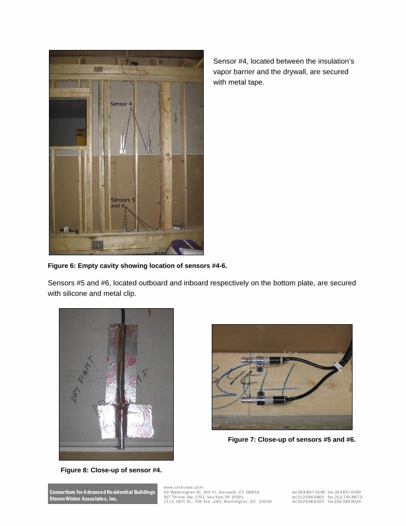
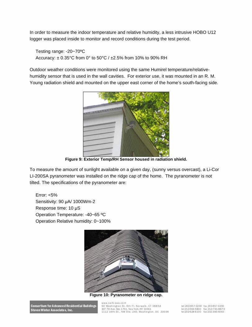
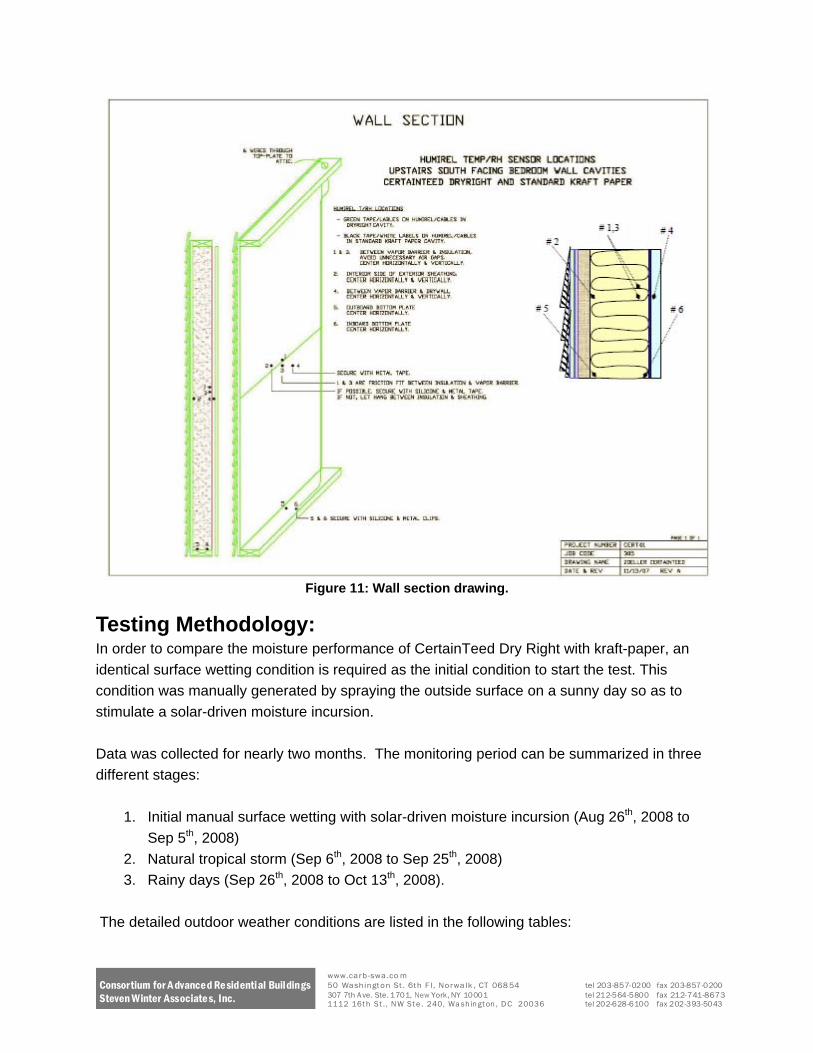
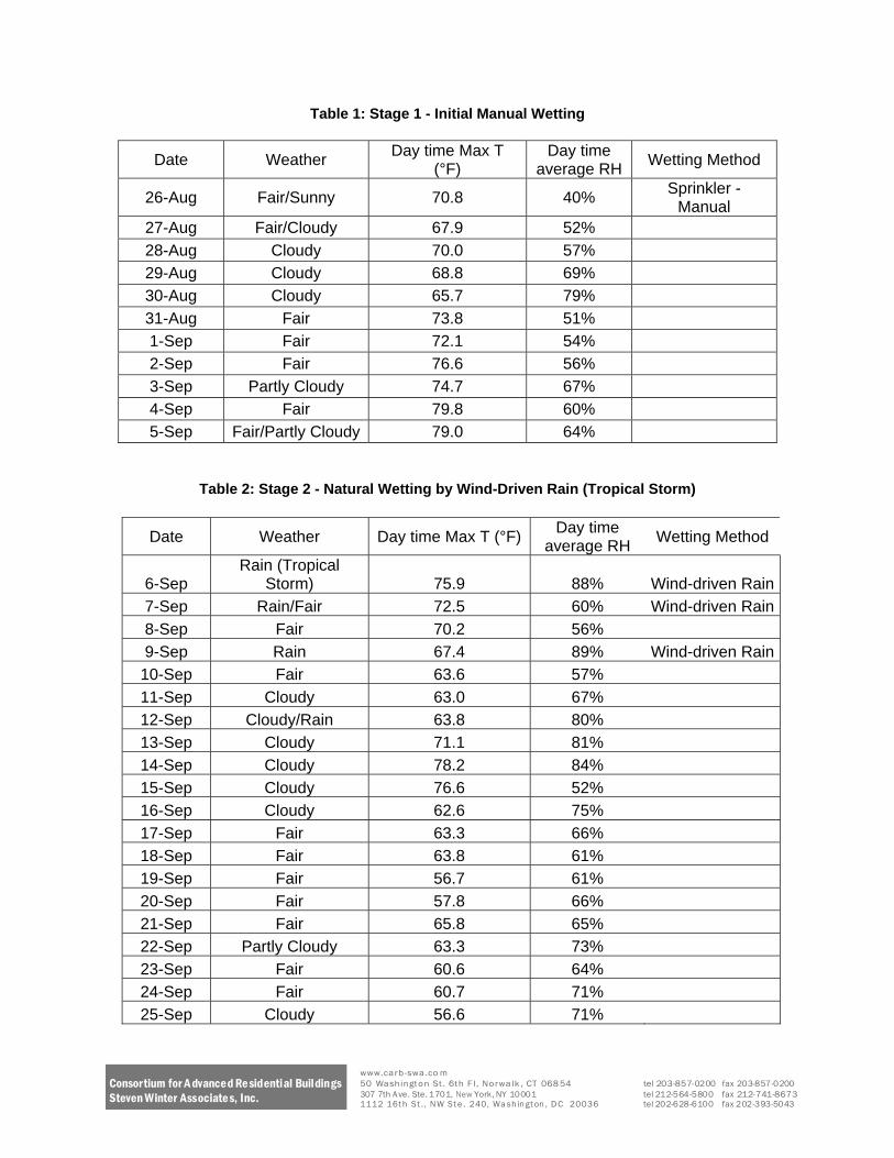
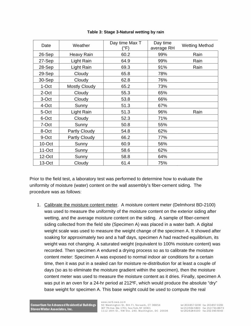
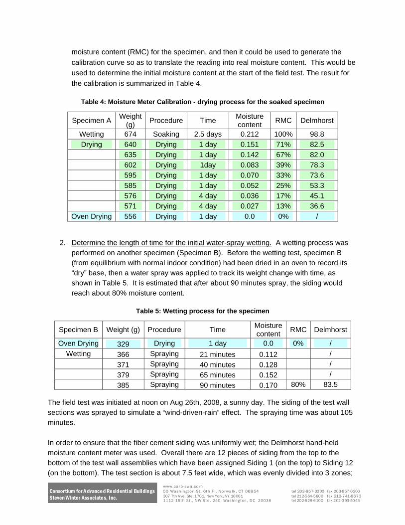
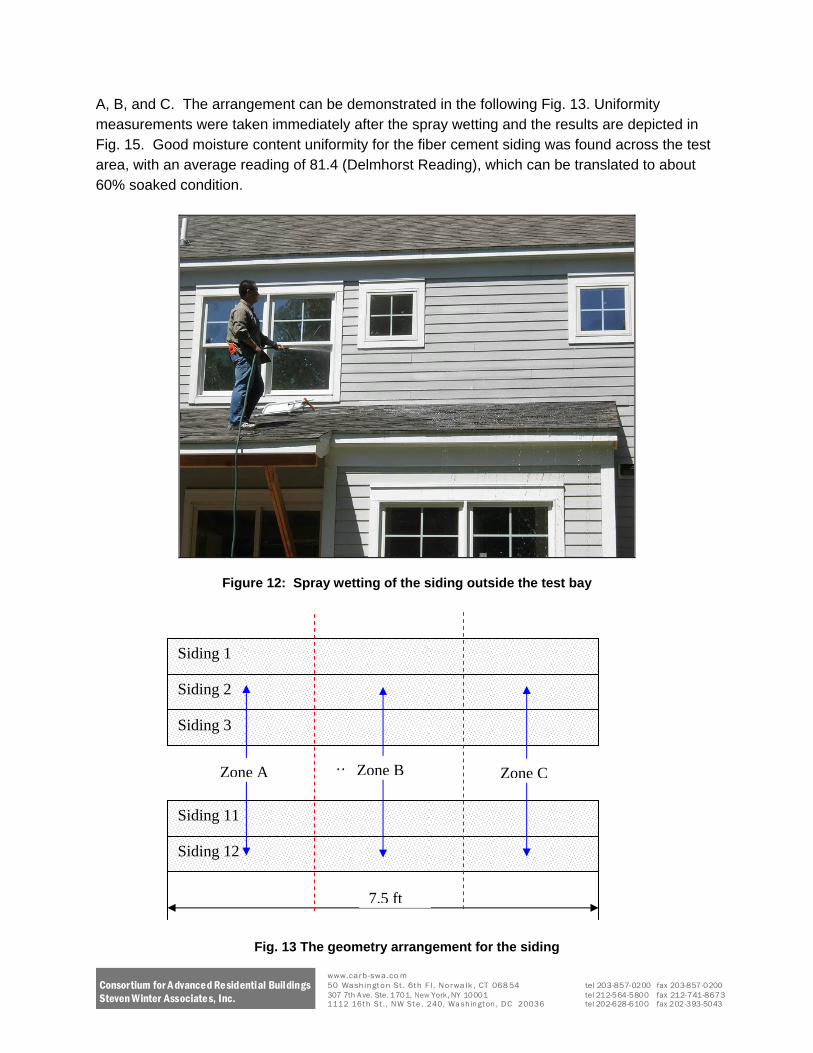
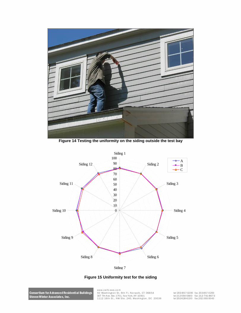
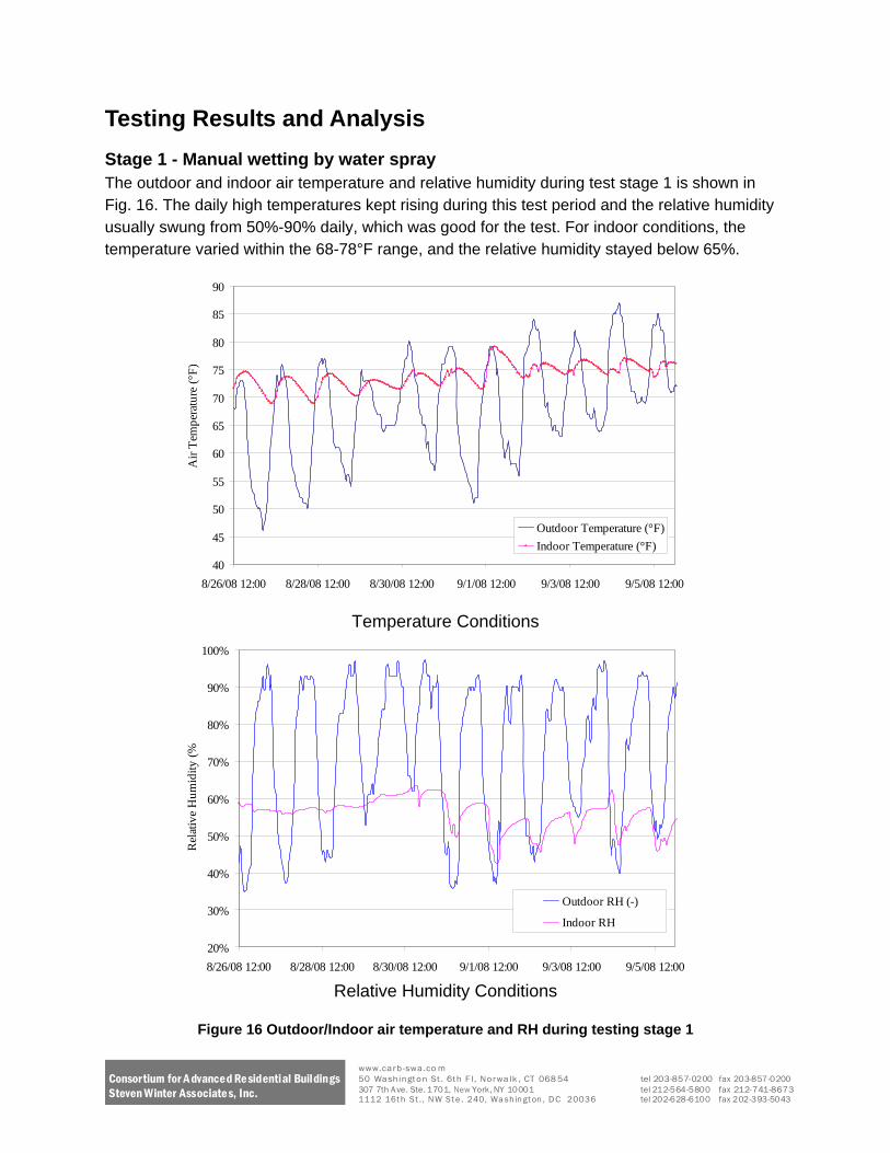
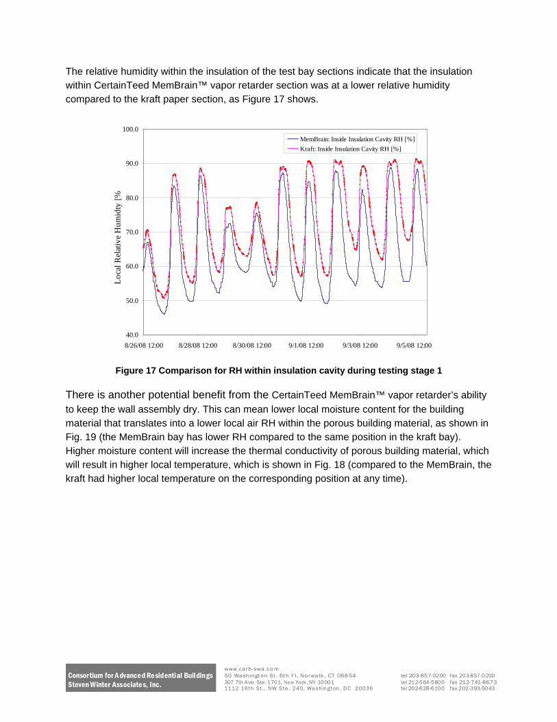
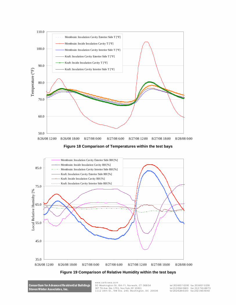
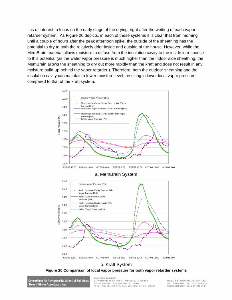
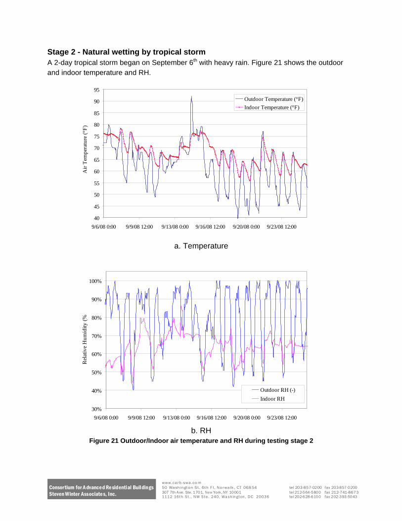
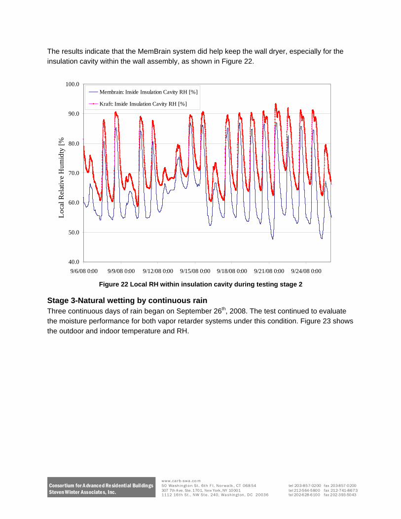
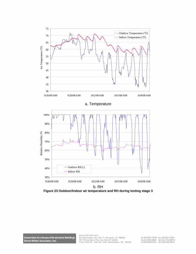
30
35
40
45
50
55
60
65
70
75
Air
Tem
pera
ture
(degF
)
Outdoor Temperature (degF)
Indoor Temperature (degF)
Rel
ativ
e H
umid
ity (
92608 000 92908 000 10208 000 10508 000 10808 000
a Temperature
100
90
80
70
60
50
Outdoor RH (-) 40 Indoor RH
30
92608 000 92908 000 10208 000 10508 000 10808 000
b RH Figure 23 OutdoorIndoor air temperature and RH during testing stage 3
Consortium for A dvanced Re sidential Buildings Steven Winter Associate s Inc
wwwcarb-swaco m 50 Washington St 6th F l Norwalk CT 068 54 tel 203-857-0200 fax 203-857-0200 307 7th A ve Ste 1701 New York NY 10001 tel 212-564-5800 fax 212-741-8673 1112 16t h St N W St e 240 Wa sh in gt on D C 20036 tel 202-628-6100 fax 202-393-5043
Again the MemBrain system kept the wall at more favorable conditions as shown in Figure 24 In most instances the MemBrain system kept the insulation cavity well below 80 local RH and successfully reduced the number of hours the local RH gt80 (80 RH is a threshold that is adopted by ASHRAE to evaluate the potential danger of mold growth due to favorable air temperature and relative humidity) Relative humidity over 80 with air temperatures from 40~100degF for a continuous 30 day time span is suggested by the ASHRAE Handbook of Fundamentals to have the potential for mold growth (ASHRAE Handbook - Fundamentals 2005)
1000 Membrain Inside Insulation Cavity RH []
Kraft Inside Insulation Cavity RH []
900
800
700
600
500
400
92608 000 92908 000 10208 000 10508 000 10808 000
Figure 24 Local RH within insulation cavity during testing stage 3
It is noticeable in Figure 25 that in the early stage of the rain wetting the RH levels within the insulation cavity for both vapor retarder bays did not swing as sharply as usual because the ambient condition of rain showers with continuous high RH (gt95 for three days) The benefits of MemBrain are most apparent in this situation Since the ambient condition is wet the outdoor sheathing is wet and the only path to avoid moisture build-up is the penetration through the vapor retarder to indoor air allowing drying to the interior Figure 25 demonstrates this result showing that the vapor pressure at the outside sheathing and the insulation cavity of the MemBrain system is much lower than the kraft system This indicates that the MemBrain system will perform better in humid and rainy areas since it provides the ldquonarrow escaperdquo for moisture to the indoor side
Loc
al R
elat
ive
Hum
idty
[
wwwcarb-swaco m Consortium for A dvanced Residential Buildings 50 Washington St 6th F l Norwalk CT 068 54 tel 203-857-0200 fax 203-857-0200
307 7th A ve Ste 1701 New York NY 10001 tel 212-564-5800 fax 212-741-8673Steven Winter Associates Inc 1112 16t h St N W St e 240 Wa sh in gt on D C 20036 tel 202-628-6100 fax 202-393-5043
Consortium for A dvanced Re sidential Buildings Steven Winter Associate s Inc
0400
0350 V
apor
Pre
ssur
e (P
si)
Vap
or P
ress
ure
(Psi
) 0300
0250
0200
Outdoor Vapor Pressure (Psi)
Membrain Insulation Cavity Exterior Side Vapor Pressure[Psi] 0150 Membrain Vapor Pressure Inside Insulation [Psi]
Membrain Insulation Cavity Interior Side Vapor Pressure[Psi] Indoor Vapor Pressure (Psi)
0100
92808 000 92808 600 92808 1200 92808 1800 92908 000
a MemBrain System
0400
0350
0300
0250
0200 Outdoor Vapor Pressure (Psi)
Kraft Insulation Cavity Exterior Side Vapor Pressure[Psi]
Kraft Vapor Pressure Inside Insulation [Psi] 0150 Kraft Insulation Cavity Interior Side Vapor Pressure[Psi]
Indoor Vapor Pressure (Psi)
0100
92808 000 92808 600 92808 1200 92808 1800 92908 000
b Kraft System
Figure 25 Comparison of local vapor pressure for both vapor retarder systems
wwwcarb-swaco m 50 Washington St 6th F l Norwalk CT 068 54 tel 203-857-0200 fax 203-857-0200 307 7th A ve Ste 1701 New York NY 10001 tel 212-564-5800 fax 212-741-8673 1112 16t h St N W St e 240 Wa sh in gt on D C 20036 tel 202-628-6100 fax 202-393-5043
Conclusions A comparison field test was performed to evaluate the moisture performance of the CertainTeed DryRight system which uses the MemBrain vapor retarder versus conventional kraft-faced batts The results indicate that
1 The relative humidity within the insulation of the test bay with the MemBrain vapor retarder was lower than the test bay with kraft paper facing
2 When the ambient conditions are very wet for a relatively long time span (several rainy days) with significant wetting to cladding and sheathing assemblies the MemBrain system can provide a moisture escape path by its variable open-pore structure allowing higher levels of drying to the interior than does standard kraft-faced batts
For more information or comments contact Zhipeng Zhong at Zhongswintercom
Limits of Liability and Disclaimer of Warranty Steven Winter Associates Inc makes no representations about the suitability of this document for all situations The accuracy and completeness of the information provided by the author and the opinions stated herein are not guaranteed or warranted to produce any particular results and the advice and strategies contained herein may not be suitable for all applications This document is provided ldquoas isrdquo without express or implied warranty Steven Winter Associates Inc shall not be liable in any event for incidental or consequential damages in connection with or arising out of the furnishing performance or use of this documentation The information presented in this article is for use with care by professionals
Consortium for A dvanced Re sidential Buildings Steven Winter Associate s Inc
wwwcarb-swaco m 50 Washington St 6th F l Norwalk CT 068 54 tel 203-857-0200 fax 203-857-0200 307 7th A ve Ste 1701 New York NY 10001 tel 212-564-5800 fax 212-741-8673 1112 16t h St N W St e 240 Wa sh in gt on D C 20036 tel 202-628-6100 fax 202-393-5043
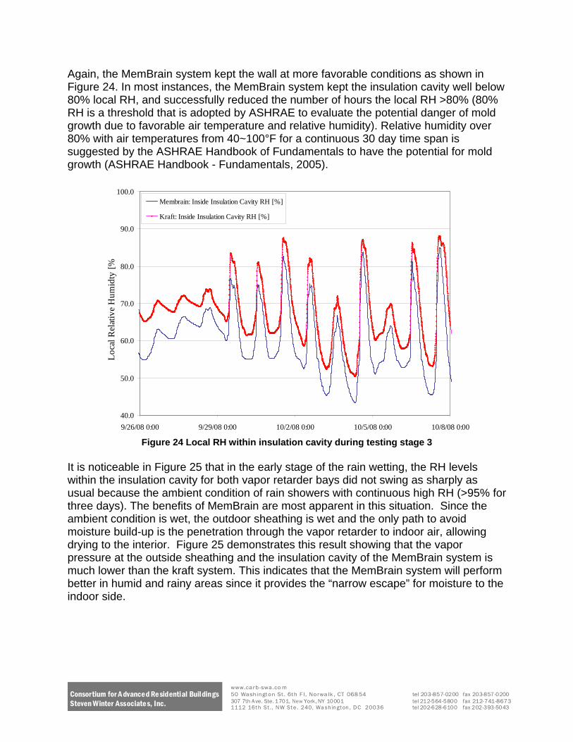
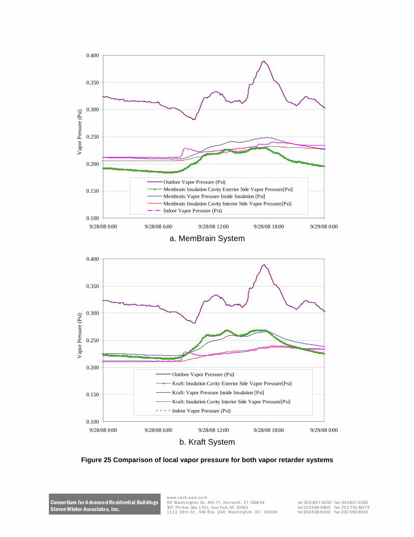
Consortium for A dvanced Re sidential Buildings Steven Winter Associate s Inc
0400
0350 V
apor
Pre
ssur
e (P
si)
Vap
or P
ress
ure
(Psi
) 0300
0250
0200
Outdoor Vapor Pressure (Psi)
Membrain Insulation Cavity Exterior Side Vapor Pressure[Psi] 0150 Membrain Vapor Pressure Inside Insulation [Psi]
Membrain Insulation Cavity Interior Side Vapor Pressure[Psi] Indoor Vapor Pressure (Psi)
0100
92808 000 92808 600 92808 1200 92808 1800 92908 000
a MemBrain System
0400
0350
0300
0250
0200 Outdoor Vapor Pressure (Psi)
Kraft Insulation Cavity Exterior Side Vapor Pressure[Psi]
Kraft Vapor Pressure Inside Insulation [Psi] 0150 Kraft Insulation Cavity Interior Side Vapor Pressure[Psi]
Indoor Vapor Pressure (Psi)
0100
92808 000 92808 600 92808 1200 92808 1800 92908 000
b Kraft System
Figure 25 Comparison of local vapor pressure for both vapor retarder systems
wwwcarb-swaco m 50 Washington St 6th F l Norwalk CT 068 54 tel 203-857-0200 fax 203-857-0200 307 7th A ve Ste 1701 New York NY 10001 tel 212-564-5800 fax 212-741-8673 1112 16t h St N W St e 240 Wa sh in gt on D C 20036 tel 202-628-6100 fax 202-393-5043
Conclusions A comparison field test was performed to evaluate the moisture performance of the CertainTeed DryRight system which uses the MemBrain vapor retarder versus conventional kraft-faced batts The results indicate that
1 The relative humidity within the insulation of the test bay with the MemBrain vapor retarder was lower than the test bay with kraft paper facing
2 When the ambient conditions are very wet for a relatively long time span (several rainy days) with significant wetting to cladding and sheathing assemblies the MemBrain system can provide a moisture escape path by its variable open-pore structure allowing higher levels of drying to the interior than does standard kraft-faced batts
For more information or comments contact Zhipeng Zhong at Zhongswintercom
Limits of Liability and Disclaimer of Warranty Steven Winter Associates Inc makes no representations about the suitability of this document for all situations The accuracy and completeness of the information provided by the author and the opinions stated herein are not guaranteed or warranted to produce any particular results and the advice and strategies contained herein may not be suitable for all applications This document is provided ldquoas isrdquo without express or implied warranty Steven Winter Associates Inc shall not be liable in any event for incidental or consequential damages in connection with or arising out of the furnishing performance or use of this documentation The information presented in this article is for use with care by professionals
Consortium for A dvanced Re sidential Buildings Steven Winter Associate s Inc
wwwcarb-swaco m 50 Washington St 6th F l Norwalk CT 068 54 tel 203-857-0200 fax 203-857-0200 307 7th A ve Ste 1701 New York NY 10001 tel 212-564-5800 fax 212-741-8673 1112 16t h St N W St e 240 Wa sh in gt on D C 20036 tel 202-628-6100 fax 202-393-5043