Embed Size (px)
Citation preview
Chief impulse - E/VHT
USERS MANUAL
2010 © Chief Automotive Technologies.
impulse -E/VHT USERS MANUAL
CHIEF'S LIMITED ONE-YEAR
WARRANTY & LIABILITY
Chief Automotive Technologies warrants for one year from date of installation
and/or purchase any components of its impulse-E/VHT Repair System which do
not perform satisfactorily due to defect caused by faulty material or workman-
ship. Chief’s obligation under this warranty is limited to the repair or replace-
ment of products which are defective and which have not been misused, care-
lessly handled, or defaced by repair or repairs made or attempted by others.
CHIEF AUTOMOTIVE TECHNOLOGIES DOES NOT ASSUME RESPONSI-
BILITY FOR ANY DEATH, INJURY OR PROPERTY DAMAGE RESULTING
FROM THE OPERATOR’S NEGLIGENCE OR MISUSE OF THIS PRODUCT
OR ITS ATTACHMENTS. CHIEF MAKES NO WRITTEN, EXPRESS OR
IMPLIED WARRANTY WHATSOEVER OF MERCHANTABILITY OR FITNESS
FOR A PARTICULAR PURPOSE OR OTHERWISE REGARDING THE EQUIP-
MENT OR ANY PART OF THE PRODUCT OTHER THAN THE LIMITED ONE-
YEAR WARRANTY STATED ABOVE.
impulse - E/VHTUSERS MANUAL
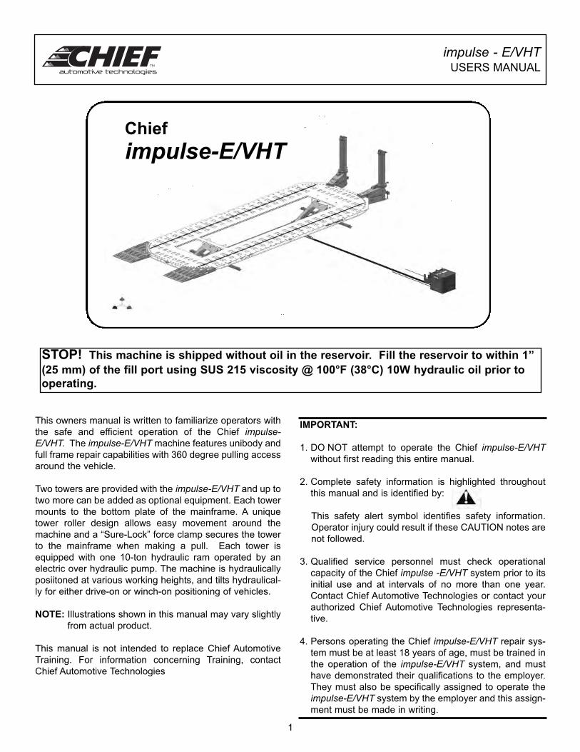
This owners manual is written to familiarize operators with
the safe and efficient operation of the Chief impulse-E/VHT. The impulse-E/VHT machine features unibody and
full frame repair capabilities with 360 degree pulling access
around the vehicle.
Two towers are provided with the impulse-E/VHT and up to
two more can be added as optional equipment. Each tower
mounts to the bottom plate of the mainframe. A unique
tower roller design allows easy movement around the
machine and a “Sure-Lock” force clamp secures the tower
to the mainframe when making a pull. Each tower is
equipped with one 10-ton hydraulic ram operated by an
electric over hydraulic pump. The machine is hydraulically
posiitoned at various working heights, and tilts hydraulical-
ly for either drive-on or winch-on positioning of vehicles.
NOTE: Illustrations shown in this manual may vary slightly
from actual product.
This manual is not intended to replace Chief Automotive
Training. For information concerning Training, contact
Chief Automotive Technologies
IMPORTANT:
1. DO NOT attempt to operate the Chief impulse-E/VHTwithout first reading this entire manual.
2. Complete safety information is highlighted throughout
this manual and is identified by:
This safety alert symbol identifies safety information.
Operator injury could result if these CAUTION notes are
not followed.
3. Qualified service personnel must check operational
capacity of the Chief impulse -E/VHT system prior to its
initial use and at intervals of no more than one year.
Contact Chief Automotive Technologies or contact your
authorized Chief Automotive Technologies representa-
tive.
4. Persons operating the Chief impulse-E/VHT repair sys-
tem must be at least 18 years of age, must be trained in
the operation of the impulse-E/VHT system, and must
have demonstrated their qualifications to the employer.
They must also be specifically assigned to operate the
impulse-E/VHT system by the employer and this assign-
ment must be made in writing.
1
Chief
impulse-E/VHT
STOP! This machine is shipped without oil in the reservoir. Fill the reservoir to within 1”
(25 mm) of the fill port using SUS 215 viscosity @ 100°F (38°C) 10W hydraulic oil prior to
operating.
impulse - E/VHTUSERS MANUAL
IMPORTANT SAFETY INSTRUCTIONS
When using your garage equipment, basic safety precautions should always be followed, including the
following:
1. Read all instructions.
2. Care must be taken as burns can occur from touching hot parts.
3. Do not operate equipment with a damaged cord or if the equipment has been dropped or
damaged - until it has been examined by a qualified service person.
4. Do not let a cord hang over the ledge of the table, bench, or counter or come in contact with
hot manifolds or moving fan blades.
5. If an extension cord is necessary, a cord with a current rating equal to or more than that of
the equipment should be used. Cords rated for less current than the equipment may
overheat. Care should be taken to arrange the cord so that it will not be tripped over or
pulled.
6. Always unplug equipment from electrical outlet when not in use. Never use the cord to pull
the plug from the outlet. Grasp plug and pull to disconnect.
7. Let equipment cool completely before putting away. Loop cord loosely around equipment
when storing.
8. To reduce the risk of fire, do no operate equipment in the vicinity of open containers of
flammable liquids (gasoline).
9. Keep hair, loose clothing, fingers and all parts of the body away from moving parts.
10. To reduce the risk of electric shock, do not use on wet surfaces or expose to rain.
11. Use only as described in this manual. Use only manufacturer’s recommended attachments.
12. ALWAYS WEAR SAFETY GLASSES. Everyday eyeglasses only have impact resistant
lenses, they are not safety glasses.
SAVE THESE INSTRUCTIONS
2
impulse - E/VHTUSERS MANUAL
General
DO NOT operate this machine unless:
1) You are authorized in writing by your employer.
2) All towers are properly secured to machine.
3) Vehicle’s wheels are blocked and parking brake is set.
4) Load is 10,000 lbs or less.
5) Field of motion of load carrying device is free of per-
sons and obstructions.
Persons operating the impulse repair system must be at
least 18 years of age, must be trained in the operation of
impulse system, and must have demonstrated their quali-
fications to the employer.
DO NOT attempt to operate the impulse pulling system
without first reading this entire manual.
Always wear safety glasses when using the impulsemachine or any of its accessories.
DO NOT move machine if vehicle is on it.
Maintain a free space of 20 inches (50cm) minimum
around all moving parts and pinch points on machine.
Optional Crossmember
DO NOT use optional crossmember as a step.
DO NOT use optional crossmember to make angular
pushes or pulls.
During removal and reinstallation of optional crossmem-
ber, hold crossmember firmly to support its weight. Use a
helper if needed. Following installation, install support pins
at each end of crossmember to prevent accident disen-
gagement.
To Avoid Damage to the lift assemblies or the hydraulic
power unit:
• Crossmember must be installed and located prop-
erly when Raising or Lowering Equipment
Collar
To avoid accidental dropping of tower collar, tighten collar
locking knob and or lower collar to bottom of tower.
Collar locking knob must be tightened before removing
tower chain from vehicle.
General Safety TipsTower Movement
When pushing tower, keep one hand on tower lever
and the other on the tower pipe above the collar.
Also, keep hands away from all pinch points...i.e.
roller assemblies on bottom mainframe plate and
force clamp pinning location on top mainframe plate.
When engaging “Sure-Lock” force clamp, k e e p
hands away from all pinch points...i.e roller assem-
blies on bottom mainframe plate and force clamp
pinning location on top mainframe plate.
NOTE: Hoses may need to be disconnected when
moving towers around the front and rear of machine.
Pulling
To prevent personal injury from flying objects:
• Check all bolts, nuts and clamps for deformation
or elongation prior to each use.
• Deformed or elongated materials must be
replaced.
• If materials look deformed, they are deformed.
Replace them.
Remove twist in chain before applying pressure to
the chain.
Raise / Lower Machine
When raising or lowering machine, secure towers to
front of mainframe. The “Sure-Lock” force clamps
must firmly engage pinning holes at that location and
tower levers must be down
Lifting of persons is prohibited.
Keep feet and objects clear of mainframe when low-
ering machine.
WARNING!
To avoid severe personal injury to yourself and
others: DO NOT position yourself close to, or in
line with chains, clamps, or other accessories
while pressure is applied to this system.
3
WARNING
Fully engage “Sure-Lock” force clamp with pinning
hole on mainframe to prevent tower movement
during the pull or during a raising or lowering pro-
cedure.
impulse - E/VHTUSERS MANUAL
To Avoid Personal Injury or Damage to Equipment:
• Before operating the machine make sure:
Persons and objects are clear of machine
Hoses and other objects are free of the lift
legs.
• Oil spills must be cleaned up immediately to prev-
ent slipping.
• Hoses on the floor can create a tripping hazard.
Loading / Unloading Machine
Prior to driving or winching vehicle on or off the
machine make sure loading ramps are
installed correctly.
When driving or winching a vehicle on or off
machine, use helper to guide you. If vehicle’s brakes
are inoperable, use a Chief Winch and refer to
instructions packaged with that accessory.
Immediately after positioning vehicle on mainframe,
put vehicle in park (if automatic transmission), apply
vehicles emergency brake, and have helper install
wheel chocks at “front” of front tire and at “rear” of
rear tire. Install wheel chocks as close to the tires as
possible to prevent vehicle movement and keep
wheel chocks installed whenever vehicle is not
anchored to mainframe.
Position vehicle far enough onto mainframe so that
wheels do not rest on loading ramps. DO NOT use
ramps to lift or hold a load off of the floor. Remove
ramps before raising machine.
Before lowering machine, put vehicle in park (if auto-
matic transmission), apply vehicles parking brake,
and install wheel chocks. Then check to make sure
loading ramps are installed correctly.
DO NOT run over air hoses or hydraulic lines when
loading or unloading vehicles.
DO NOT exceed the machine’s 10,000 lbs. (4,535
kg.) lifting capacity.
When raising or lowering machine with vehicle
aboard, DO NOT walk behind rear of machine.
Always install wheel chocks when raising or lowering
machine with a vehicle aboard.
Chain
The 1/2” tower chain is proof tested to 28,000 lbs.
(124kN).
To avoid personal injury or damage to property, DO
NOT:
• Heat chain or hook while repairing vehicle. 600
degrees F (316 degrees C) of heat on chain will
weaken it.
• Tip load chain hook.
• Pull with twisted chain links.
Hydraulics
Keep pumps far away from excessive heat or
flames. The surrounding temperature should not
exceed 122° F (50° C).
Always release hydraulic pressure before discon-
necting hydraulic hoses.
If pump fails to shut off, disconnect electric supply
and contact an authorized Chief Automotive
Technologies Service Representative.
All components must be replaced with Chief
Automotive Technologies authorized replacement
parts.
Improper handling and/or modification of parts is for-
bidden and may cause a hazardous situation for the
user. Such action immediately voids the warranty
and releases the manufacturer from all liability.
Keep pump in upright position. DO NOT turn pump
upside down or lay on its side.
1. Fill pump reservoir with all cylinders retracted
and deck in lowest working position. (See
Maintenance Section - page 14.)
2. DO NOT overfill pump reservoir.
Operational Capacity
Qualified service personnel must check operational
capacity of impulse system prior to its initial use and
at intervals of no more than one year. Contact Chief
Automotive Technologies or contact your authorized
Chief Automotive Technologies representative.
Optional Steps / Ladders
Use only approved steps and ladders when working
on or around this equipment.
General Safety Tips (continued)
4
impulse - E/VHTUSERS MANUAL
Hydraulic System Components
The Chief E/VHT system is powered by an electrically
operated hydraulic pump which is controlled by a remote
control switch. Refer to the E/VHT Parts Manual (Chief
#450429) for component detail.
Hydraulic pressure is distributed to tower cylinders, auxil-
iary cylinders, and lift cylinders. The flow of hydraulic fluid
to tower and auxiliary cylinders is controlled by individual
valves located in each auxiliary line. The flow of hydraulic
fluid to the lift cylinders is controlled by an electric switch
mounted on the pump cabinet top panel. Hydraulic pres-
sure is monitored by gauges mounted on the towers. To
exert hydraulic pressure, press “UP” button on the hand-
held control unit. To release hydraulic pressure, press
“DOWN” button.
NOTE: Although the E/VHT is a low pressure system, it
builds hydraulic pressure quickly. Be aware of
this quick reaction when making pulls or lifting
vehicles.
Important: Tower cylinders and auxiliary cylinders can be
operated either simultaneously (with equal
hydraulic pressure) or individually. The lift
cylinders must not be operated while any tower or
auxiliary cylinders are operating. When ever
using the hydraulic system, close all valves where
hydraulic pressure is not required.
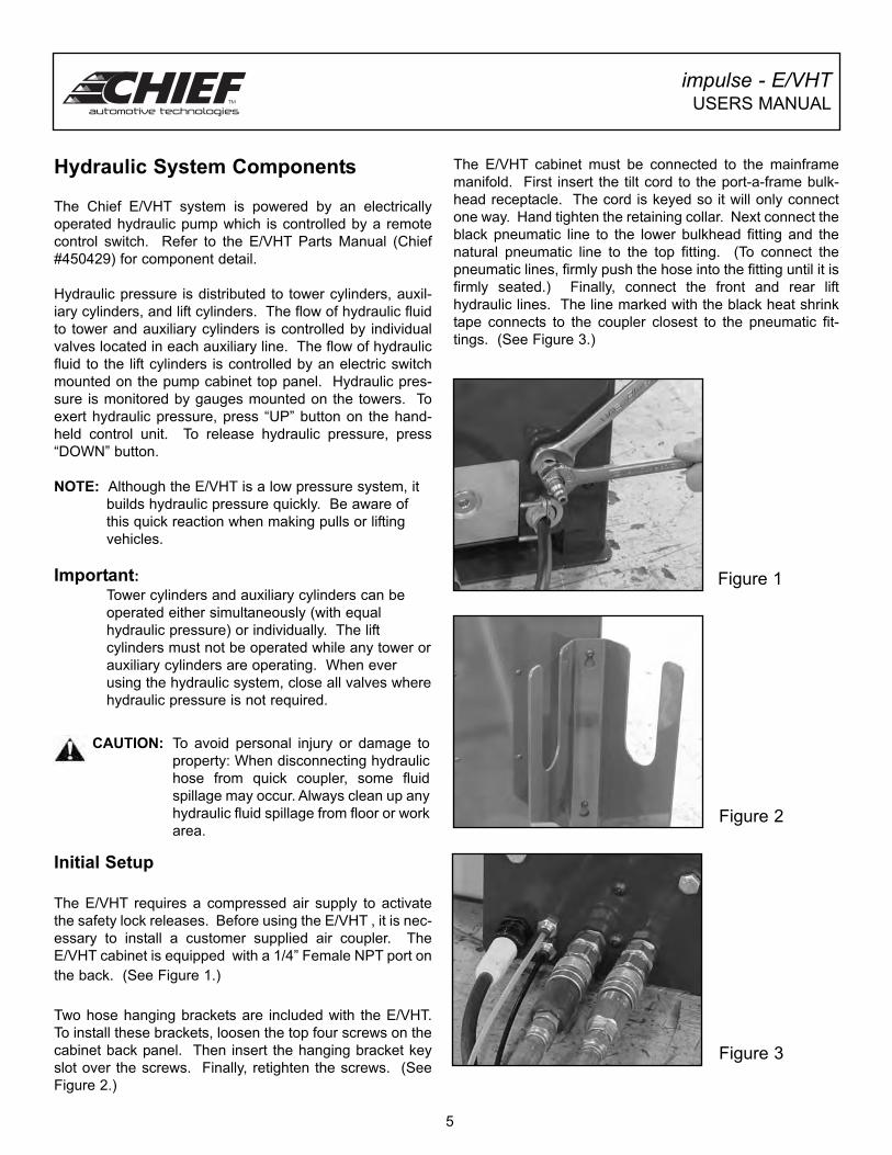
Initial Setup
The E/VHT requires a compressed air supply to activate
the safety lock releases. Before using the E/VHT , it is nec-
essary to install a customer supplied air coupler. The
E/VHT cabinet is equipped with a 1/4” Female NPT port on
the back. (See Figure 1.)
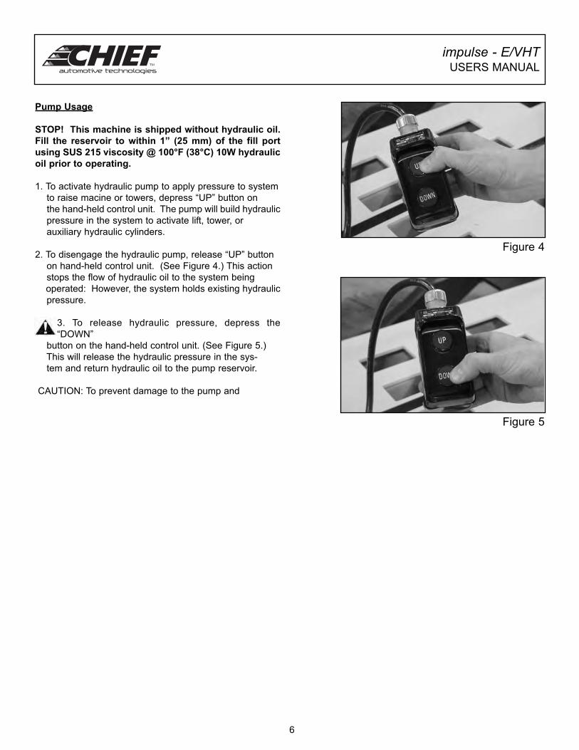
Two hose hanging brackets are included with the E/VHT.
To install these brackets, loosen the top four screws on the
cabinet back panel. Then insert the hanging bracket key
slot over the screws. Finally, retighten the screws. (See
Figure 2.)
5
CAUTION: To avoid personal injury or damage to
property: When disconnecting hydraulic
hose from quick coupler, some fluid
spillage may occur. Always clean up any
hydraulic fluid spillage from floor or work
area.
Figure 1
Figure 2
Figure 3
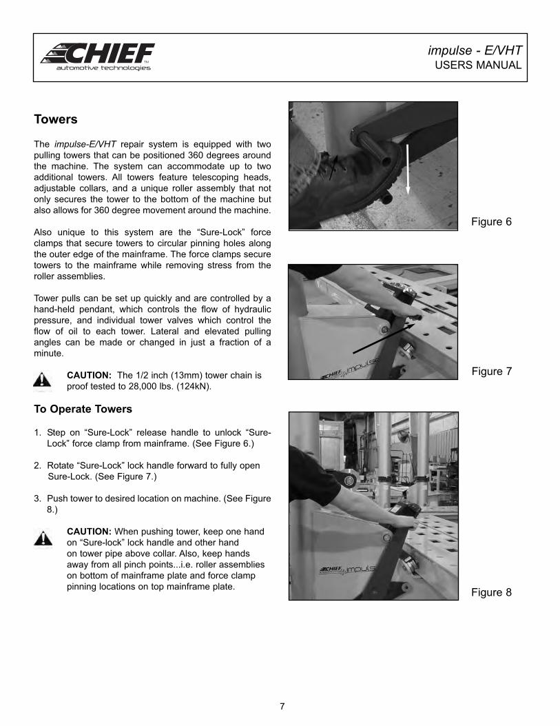
The E/VHT cabinet must be connected to the mainframe
manifold. First insert the tilt cord to the port-a-frame bulk-
head receptacle. The cord is keyed so it will only connect
one way. Hand tighten the retaining collar. Next connect the
black pneumatic line to the lower bulkhead fitting and the
natural pneumatic line to the top fitting. (To connect the
pneumatic lines, firmly push the hose into the fitting until it is
firmly seated.) Finally, connect the front and rear lift
hydraulic lines. The line marked with the black heat shrink
tape connects to the coupler closest to the pneumatic fit-
tings. (See Figure 3.)
impulse - E/VHTUSERS MANUAL
Pump Usage
STOP! This machine is shipped without hydraulic oil.
Fill the reservoir to within 1” (25 mm) of the fill port
using SUS 215 viscosity @ 100°F (38°C) 10W hydraulic
oil prior to operating.
1. To activate hydraulic pump to apply pressure to system
to raise macine or towers, depress “UP” button on
the hand-held control unit. The pump will build hydraulic
pressure in the system to activate lift, tower, or
auxiliary hydraulic cylinders.
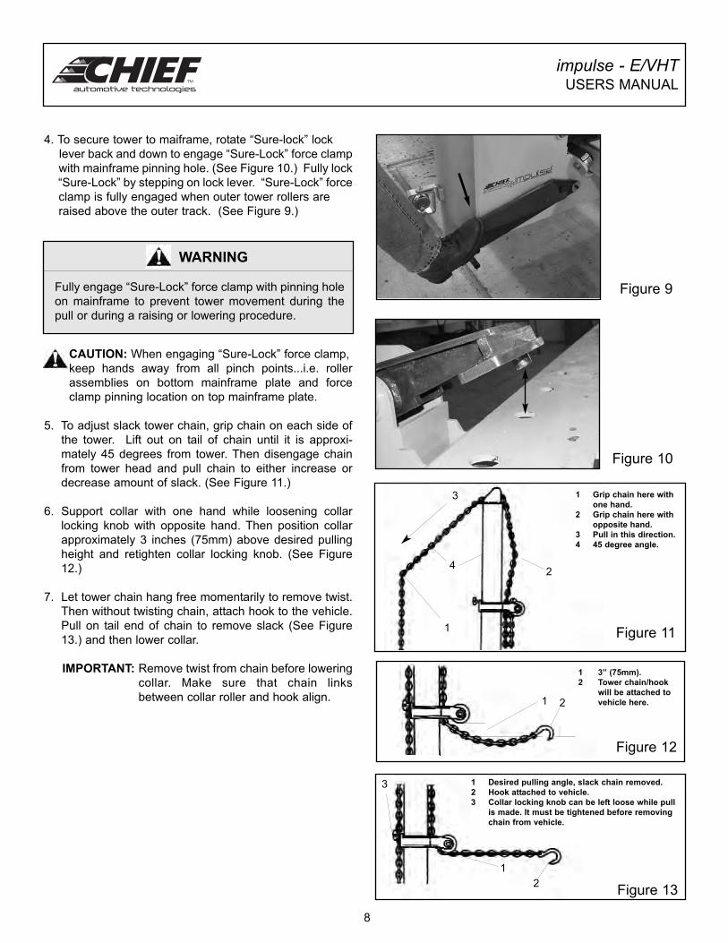
2. To disengage the hydraulic pump, release “UP” button
on hand-held control unit. (See Figure 4.) This action
stops the flow of hydraulic oil to the system being
operated: However, the system holds existing hydraulic
pressure.
3. To release hydraulic pressure, depress the
“DOWN”
button on the hand-held control unit. (See Figure 5.)
This will release the hydraulic pressure in the sys-
tem and return hydraulic oil to the pump reservoir.
CAUTION: To prevent damage to the pump and
Figure 4
6
Figure 5
impulse - E/VHTUSERS MANUAL
Towers
The impulse-E/VHT repair system is equipped with two
pulling towers that can be positioned 360 degrees around
the machine. The system can accommodate up to two
additional towers. All towers feature telescoping heads,
adjustable collars, and a unique roller assembly that not
only secures the tower to the bottom of the machine but
also allows for 360 degree movement around the machine.
Also unique to this system are the “Sure-Lock” force
clamps that secure towers to circular pinning holes along
the outer edge of the mainframe. The force clamps secure
towers to the mainframe while removing stress from the
roller assemblies.
Tower pulls can be set up quickly and are controlled by a
hand-held pendant, which controls the flow of hydraulic
pressure, and individual tower valves which control the
flow of oil to each tower. Lateral and elevated pulling
angles can be made or changed in just a fraction of a
minute.
CAUTION: The 1/2 inch (13mm) tower chain is
proof tested to 28,000 lbs. (124kN).
To Operate Towers
1. Step on “Sure-Lock” release handle to unlock “Sure-
Lock” force clamp from mainframe. (See Figure 6.)
2. Rotate “Sure-Lock” lock handle forward to fully open
Sure-Lock. (See Figure 7.)
3. Push tower to desired location on machine. (See Figure
8.)
CAUTION: When pushing tower, keep one hand
on “Sure-lock” lock handle and other hand
on tower pipe above collar. Also, keep hands
away from all pinch points...i.e. roller assemblies
on bottom of mainframe plate and force clamp
pinning locations on top mainframe plate.
Figure 6
Figure 7
Figure 8
7
impulse - E/VHTUSERS MANUAL
4. To secure tower to maiframe, rotate “Sure-lock” lock
lever back and down to engage “Sure-Lock” force clamp
with mainframe pinning hole. (See Figure 10.) Fully lock
“Sure-Lock” by stepping on lock lever. “Sure-Lock” force
clamp is fully engaged when outer tower rollers are
raised above the outer track. (See Figure 9.)
CAUTION: When engaging “Sure-Lock” force clamp,
keep hands away from all pinch points...i.e. roller
assemblies on bottom mainframe plate and force
clamp pinning location on top mainframe plate.
5. To adjust slack tower chain, grip chain on each side of
the tower. Lift out on tail of chain until it is approxi-
mately 45 degrees from tower. Then disengage chain
from tower head and pull chain to either increase or
decrease amount of slack. (See Figure 11.)
6. Support collar with one hand while loosening collar
locking knob with opposite hand. Then position collar
approximately 3 inches (75mm) above desired pulling
height and retighten collar locking knob. (See Figure
12.)
7. Let tower chain hang free momentarily to remove twist.
Then without twisting chain, attach hook to the vehicle.
Pull on tail end of chain to remove slack (See Figure
13.) and then lower collar.
IMPORTANT: Remove twist from chain before lowering
collar. Make sure that chain links
between collar roller and hook align.
1
2
3
4
1 Grip chain here with
one hand.
2 Grip chain here with
opposite hand.
3 Pull in this direction.
4 45 degree angle.
Figure 11
1 2
1 3” (75mm).
2 Tower chain/hook
will be attached to
vehicle here.
Figure 12
Figure 13
1 Desired pulling angle, slack chain removed.
2 Hook attached to vehicle.
3 Collar locking knob can be left loose while pull
is made. It must be tightened before removing
chain from vehicle.
1
3
2
Figure 9
Figure 10
8
WARNING
Fully engage “Sure-Lock” force clamp with pinning hole
on mainframe to prevent tower movement during the
pull or during a raising or lowering procedure.
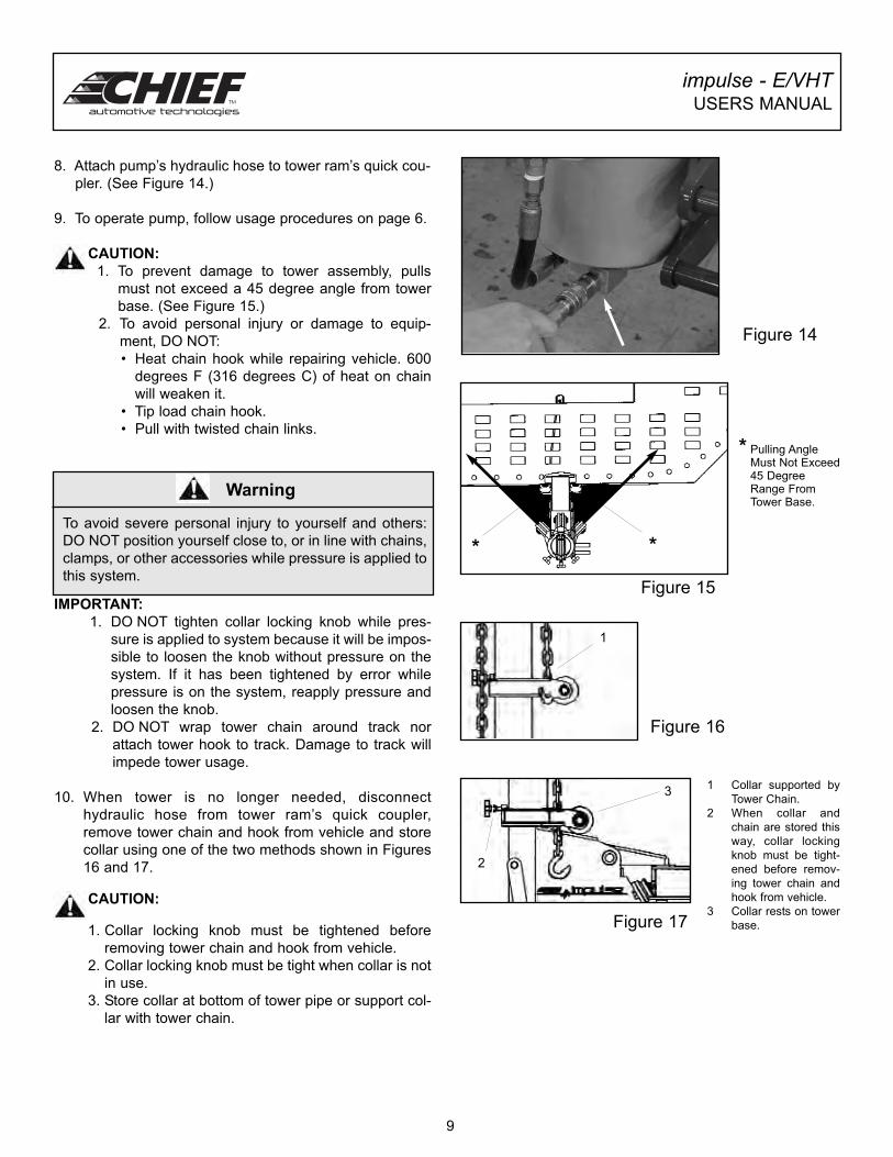
8. Attach pump’s hydraulic hose to tower ram’s quick cou-
pler. (See Figure 14.)
9. To operate pump, follow usage procedures on page 6.
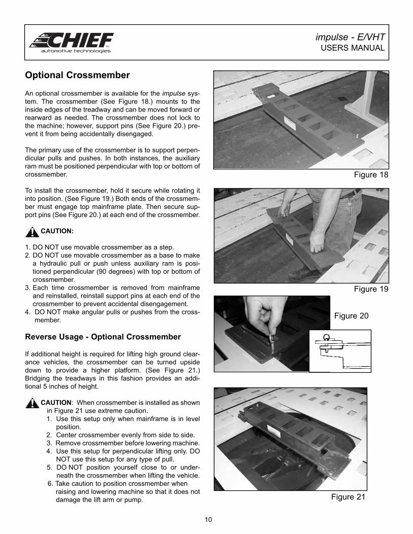
CAUTION:
1. To prevent damage to tower assembly, pulls
must not exceed a 45 degree angle from tower
base. (See Figure 15.)
2. To avoid personal injury or damage to equip-
ment, DO NOT:
• Heat chain hook while repairing vehicle. 600
degrees F (316 degrees C) of heat on chain
will weaken it.
• Tip load chain hook.
• Pull with twisted chain links.
IMPORTANT:
1. DO NOT tighten collar locking knob while pres-
sure is applied to system because it will be impos-
sible to loosen the knob without pressure on the
system. If it has been tightened by error while
pressure is on the system, reapply pressure and
loosen the knob.
2. DO NOT wrap tower chain around track nor
attach tower hook to track. Damage to track will
impede tower usage.
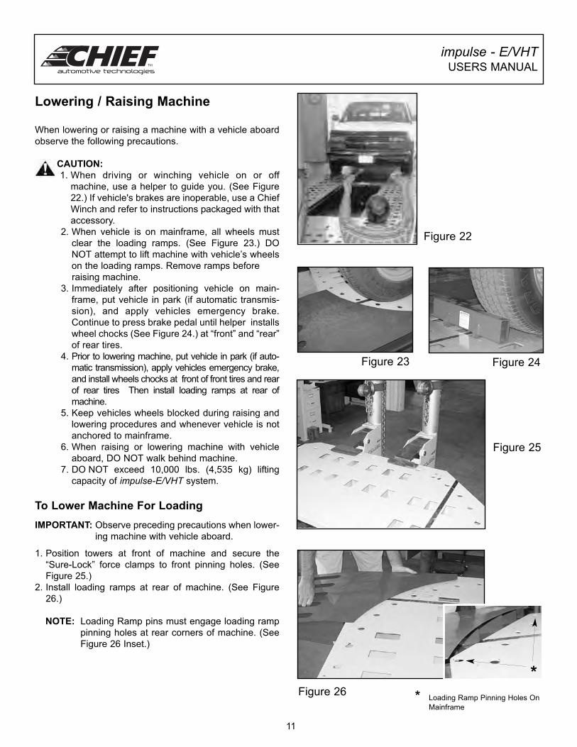
10. When tower is no longer needed, disconnect
hydraulic hose from tower ram’s quick coupler,
remove tower chain and hook from vehicle and store
collar using one of the two methods shown in Figures
16 and 17.
CAUTION:
1. Collar locking knob must be tightened before
removing tower chain and hook from vehicle.
2. Collar locking knob must be tight when collar is not
in use.
3. Store collar at bottom of tower pipe or support col-
lar with tower chain.
Figure 16
impulse - E/VHTUSERS MANUAL
To avoid severe personal injury to yourself and others:
DO NOT position yourself close to, or in line with chains,
clamps, or other accessories while pressure is applied to
this system.
Warning
Figure 14
Figure 15
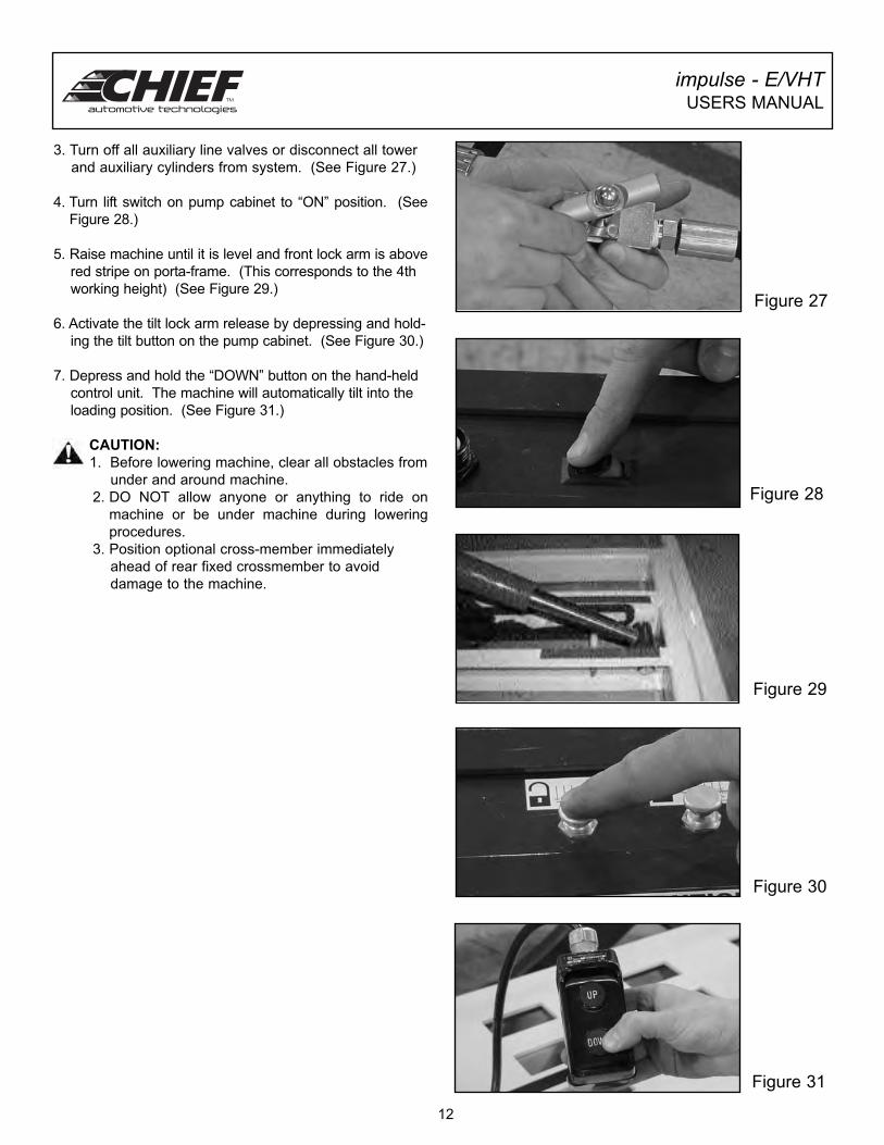
Figure 17
1 Collar supported by
Tower Chain.
2 When collar and
chain are stored this
way, collar locking
knob must be tight-
ened before remov-
ing tower chain and
hook from vehicle.
3 Collar rests on tower
base.
9
* Pulling AngleMust Not Exceed45 DegreeRange FromTower Base.
**
3
1
2
impulse - E/VHTUSERS MANUAL
Optional Crossmember
An optional crossmember is available for the impulse sys-
tem. The crossmember (See Figure 18.) mounts to the
inside edges of the treadway and can be moved forward or
rearward as needed. The crossmember does not lock to
the machine; however, support pins (See Figure 20.) pre-
vent it from being accidentally disengaged.
The primary use of the crossmember is to support perpen-
dicular pulls and pushes. In both instances, the auxiliary
ram must be positioned perpendicular with top or bottom of
crossmember.
To install the crossmember, hold it secure while rotating it
into position. (See Figure 19.) Both ends of the crossmem-
ber must engage top mainframe plate. Then secure sup-
port pins (See Figure 20.) at each end of the crossmember.
CAUTION:
1. DO NOT use movable crossmember as a step.
2. DO NOT use movable crossmember as a base to make
a hydraulic pull or push unless auxiliary ram is posi-
tioned perpendicular (90 degrees) with top or bottom of
crossmember.
3. Each time crossmember is removed from mainframe
and reinstalled, reinstall support pins at each end of the
crossmember to prevent accidental disengagement.
4. DO NOT make angular pulls or pushes from the cross-
member.
Reverse Usage - Optional Crossmember
If additional height is required for lifting high ground clear-
ance vehicles, the crossmember can be turned upside
down to provide a higher platform. (See Figure 21.)
Bridging the treadways in this fashion provides an addi-
tional 5 inches of height.
CAUTION: When crossmember is installed as shown
in Figure 21 use extreme caution.
1. Use this setup only when mainframe is in level
position.
2. Center crossmember evenly from side to side.
3. Remove crossmember before lowering machine.
4. Use this setup for perpendicular lifting only. DO
NOT use this setup for any type of pull.
5. DO NOT position yourself close to or under-
neath the crossmember when lifting the vehicle.
6. Take caution to position crossmember when
raising and lowering machine so that it does not
damage the lift arm or pump.
Figure 18
Figure 19
Figure 20
Figure 21
10
impulse - E/VHTUSERS MANUAL
When lowering or raising a machine with a vehicle aboard
observe the following precautions.
CAUTION:
1. When driving or winching vehicle on or off
machine, use a helper to guide you. (See Figure
22.) If vehicle's brakes are inoperable, use a Chief
Winch and refer to instructions packaged with that
accessory.
2. When vehicle is on mainframe, all wheels must
clear the loading ramps. (See Figure 23.) DO
NOT attempt to lift machine with vehicle’s wheels
on the loading ramps. Remove ramps before
raising machine.
3. Immediately after positioning vehicle on main-
frame, put vehicle in park (if automatic transmis-
sion), and apply vehicles emergency brake.
Continue to press brake pedal until helper installs
wheel chocks (See Figure 24.) at “front” and “rear”
of rear tires.
4. Prior to lowering machine, put vehicle in park (if auto-
matic transmission), apply vehicles emergency brake,
and install wheels chocks at front of front tires and rear
of rear tires Then install loading ramps at rear of
machine.
5. Keep vehicles wheels blocked during raising and
lowering procedures and whenever vehicle is not
anchored to mainframe.
6. When raising or lowering machine with vehicle
aboard, DO NOT walk behind machine.
7. DO NOT exceed 10,000 lbs. (4,535 kg) lifting
capacity of impulse-E/VHT system.
To Lower Machine For Loading
IMPORTANT: Observe preceding precautions when lower-
ing machine with vehicle aboard.
1. Position towers at front of machine and secure the
“Sure-Lock” force clamps to front pinning holes. (See
Figure 25.)
2. Install loading ramps at rear of machine. (See Figure
26.)
NOTE: Loading Ramp pins must engage loading ramp
pinning holes at rear corners of machine. (See
Figure 26 Inset.)
*Figure 26 * Loading Ramp Pinning Holes On
Mainframe
Figure 25
11
Lowering / Raising Machine
Figure 23 Figure 24
Figure 22
impulse - E/VHTUSERS MANUAL
3. Turn off all auxiliary line valves or disconnect all tower
and auxiliary cylinders from system. (See Figure 27.)
4. Turn lift switch on pump cabinet to “ON” position. (See
Figure 28.)
5. Raise machine until it is level and front lock arm is above
red stripe on porta-frame. (This corresponds to the 4th
working height) (See Figure 29.)
6. Activate the tilt lock arm release by depressing and hold-
ing the tilt button on the pump cabinet. (See Figure 30.)
7. Depress and hold the “DOWN” button on the hand-held
control unit. The machine will automatically tilt into the
loading position. (See Figure 31.)
CAUTION:
1. Before lowering machine, clear all obstacles from
under and around machine.
2. DO NOT allow anyone or anything to ride on
machine or be under machine during lowering
procedures.
3. Position optional cross-member immediately
ahead of rear fixed crossmember to avoid
damage to the machine.
12
Figure 31
Figure 30
Figure 29
Figure 27
Figure 28
impulse - E/VHTUSERS MANUAL
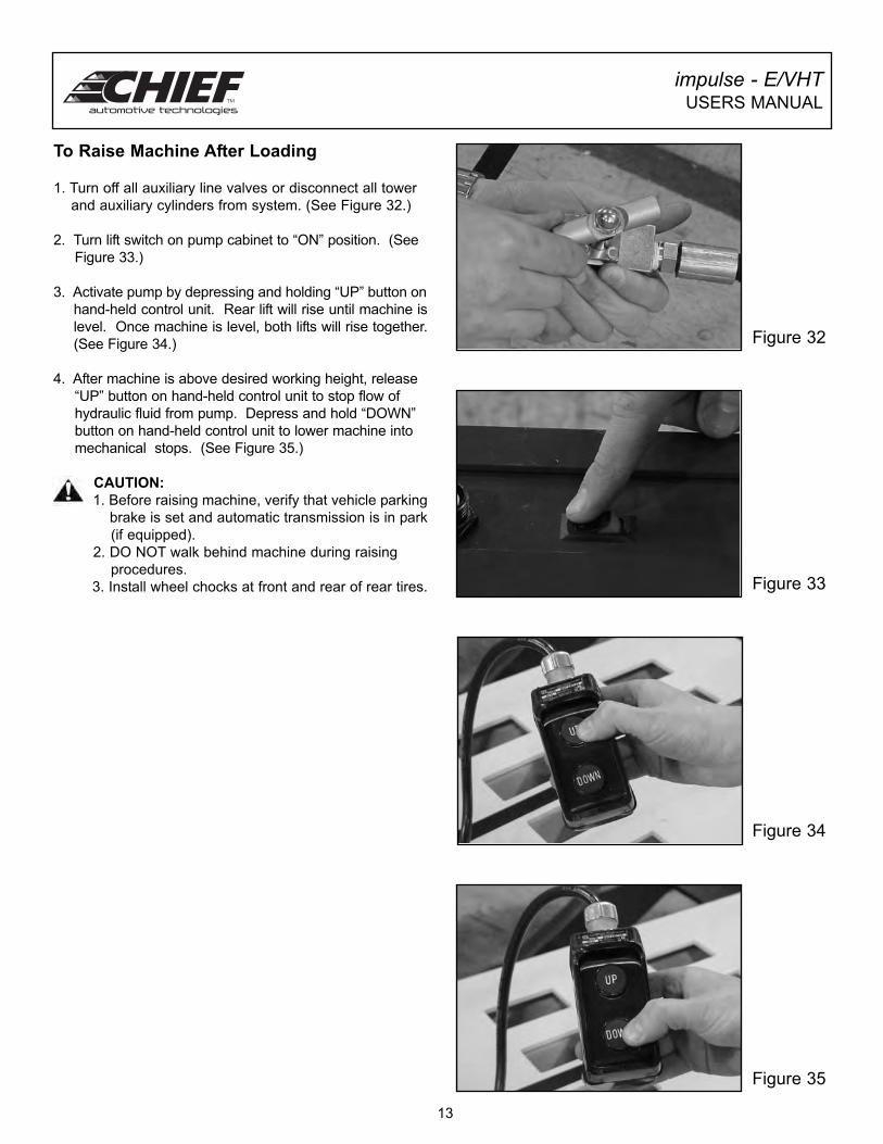
To Raise Machine After Loading
1. Turn off all auxiliary line valves or disconnect all tower
and auxiliary cylinders from system. (See Figure 32.)
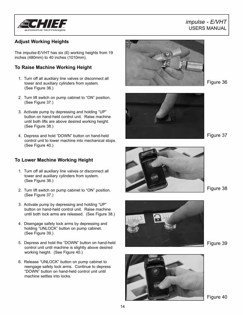
2. Turn lift switch on pump cabinet to “ON” position. (See
Figure 33.)
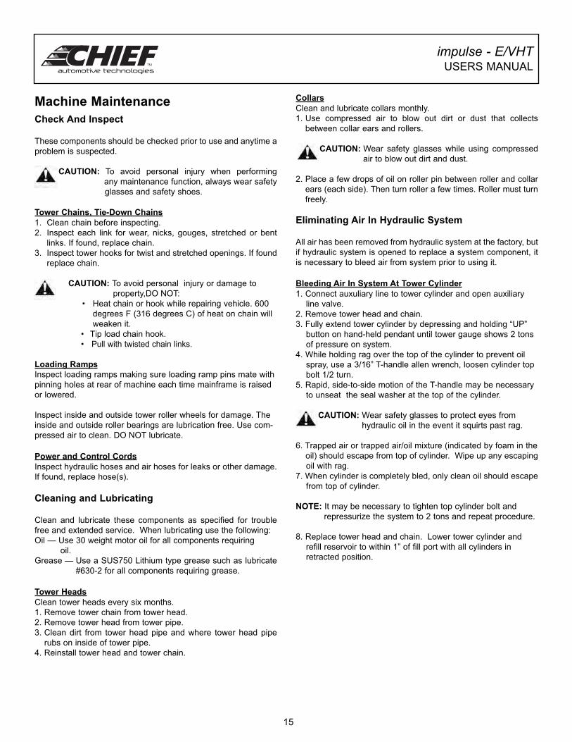
3. Activate pump by depressing and holding “UP” button on
hand-held control unit. Rear lift will rise until machine is
level. Once machine is level, both lifts will rise together.
(See Figure 34.)
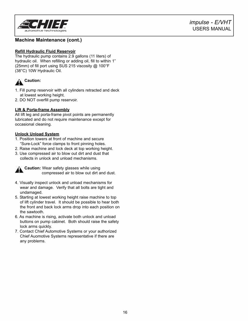
4. After machine is above desired working height, release
“UP” button on hand-held control unit to stop flow of
hydraulic fluid from pump. Depress and hold “DOWN”
button on hand-held control unit to lower machine into
mechanical stops. (See Figure 35.)
CAUTION:
1. Before raising machine, verify that vehicle parking
brake is set and automatic transmission is in park
(if equipped).
2. DO NOT walk behind machine during raising
procedures.
3. Install wheel chocks at front and rear of rear tires. Figure 33
Figure 35
Figure 34
Figure 32
13
Adjust Working Heights
The impulse-E/VHT has six (6) working heights from 19
inches (480mm) to 40 inches (1010mm).
To Raise Machine Working Height
1. Turn off all auxiliary line valves or disconnect all
tower and auxiliary cylinders from system.
(See Figure 36.)
2. Turn lift switch on pump cabinet to “ON” position.
(See Figure 37.)
3. Activate pump by depressing and holding ”UP”
button on hand-held control unit. Raise machine
until both lifts are above desired working height.
(See Figure 38.)
4. Depress and hold “DOWN” button on hand-held
control unit to lower machine into mechanical stops.
(See Figure 40.)
To Lower Machine Working Height
1. Turn off all auxiliary line valves or disconnect all
tower and auxiliary cylinders from system.
(See Figure 36.)
2. Turn lift switch on pump cabinet to “ON” position.
(See Figure 37.)
3. Activate pump by depressing and holding “UP”
button on hand-held control unit. Raise machine
until both lock arms are released. (See Figure 38.)
4. Disengage safety lock arms by depressing and
holding “UNLOCK” button on pump cabinet.
(See Figure 39.)
5. Depress and hold the “DOWN” button on hand-held
control unit until machine is slightly above desired
working height. (See Figure 40.)
6. Release “UNLOCK” button on pump cabinet to
reengage safety lock arms. Continue to depress
“DOWN” button on hand-held control unit until
machine settles into locks.
impulse - E/VHTUSERS MANUAL
14
Figure 37
Figure 38
Figure 39
Figure 40
Figure 36
Check And Inspect
These components should be checked prior to use and anytime a
problem is suspected.
CAUTION: To avoid personal injury when performing
any maintenance function, always wear safety
glasses and safety shoes.
Tower Chains, Tie-Down Chains
1. Clean chain before inspecting.
2. Inspect each link for wear, nicks, gouges, stretched or bent
links. If found, replace chain.
3. Inspect tower hooks for twist and stretched openings. If found
replace chain.
CAUTION: To avoid personal injury or damage to
property,DO NOT:
• Heat chain or hook while repairing vehicle. 600
degrees F (316 degrees C) of heat on chain will
weaken it.
• Tip load chain hook.
• Pull with twisted chain links.
Loading Ramps
Inspect loading ramps making sure loading ramp pins mate with
pinning holes at rear of machine each time mainframe is raised
or lowered.
Inspect inside and outside tower roller wheels for damage. The
inside and outside roller bearings are lubrication free. Use com-
pressed air to clean. DO NOT lubricate.
Power and Control Cords
Inspect hydraulic hoses and air hoses for leaks or other damage.
If found, replace hose(s).
Cleaning and Lubricating
Clean and lubricate these components as specified for trouble
free and extended service. When lubricating use the following:
Oil — Use 30 weight motor oil for all components requiring
oil.
Grease — Use a SUS750 Lithium type grease such as lubricate
#630-2 for all components requiring grease.
Tower Heads
Clean tower heads every six months.
1. Remove tower chain from tower head.
2. Remove tower head from tower pipe.
3. Clean dirt from tower head pipe and where tower head pipe
rubs on inside of tower pipe.
4. Reinstall tower head and tower chain.
Collars
Clean and lubricate collars monthly.
1. Use compressed air to blow out dirt or dust that collects
between collar ears and rollers.
CAUTION: Wear safety glasses while using compressed
air to blow out dirt and dust.
2. Place a few drops of oil on roller pin between roller and collar
ears (each side). Then turn roller a few times. Roller must turn
freely.
Eliminating Air In Hydraulic System
All air has been removed from hydraulic system at the factory, but
if hydraulic system is opened to replace a system component, it
is necessary to bleed air from system prior to using it.
Bleeding Air In System At Tower Cylinder
1. Connect auxuliary line to tower cylinder and open auxiliary
line valve.
2. Remove tower head and chain.
3. Fully extend tower cylinder by depressing and holding “UP”
button on hand-held pendant until tower gauge shows 2 tons
of pressure on system.
4. While holding rag over the top of the cylinder to prevent oil
spray, use a 3/16” T-handle allen wrench, loosen cylinder top
bolt 1/2 turn.
5. Rapid, side-to-side motion of the T-handle may be necessary
to unseat the seal washer at the top of the cylinder.
CAUTION: Wear safety glasses to protect eyes from
hydraulic oil in the event it squirts past rag.
6. Trapped air or trapped air/oil mixture (indicated by foam in the
oil) should escape from top of cylinder. Wipe up any escaping
oil with rag.
7. When cylinder is completely bled, only clean oil should escape
from top of cylinder.
NOTE: It may be necessary to tighten top cylinder bolt and
repressurize the system to 2 tons and repeat procedure.
8. Replace tower head and chain. Lower tower cylinder and
refill reservoir to within 1” of fill port with all cylinders in
retracted position.
15
Machine Maintenance
impulse - E/VHTUSERS MANUAL
Machine Maintenance (cont.)
Refill Hydraulic Fluid Reservoir
The hydraulic pump contains 2.9 gallons (11 liters) of
hydraulic oil. When refilling or adding oil, fill to within 1”
(25mm) of fill port using SUS 215 viscosity @ 100°F
(38°C) 10W Hydraulic Oil.
Caution:
1. Fill pump reservoir with all cylinders retracted and deck
at lowest working height.
2. DO NOT overfill pump reservoir.
LIft & Porta-frame Assembly
All lift leg and porta-frame pivot points are permanently
lubricated and do not require maintenance except for
occasional cleaning.
Unlock Unload System
1. Position towers at front of machine and secure
“Sure-Lock” force clamps to front pinning holes.
2. Raise machine and lock deck at top working height.
3. Use compressed air to blow out dirt and dust that
collects in unlock and unload mechanisms.
Caution: Wear safety glasses while using
compressed air to blow out dirt and dust.
4. Visually inspect unlock and unload mechanisms for
wear and damage. Verify that all bolts are tight and
undamaged.
5. Starting at lowest working height raise machine to top
of lift cylinder travel. It should be possible to hear both
the front and back lock arms drop into each position on
the sawtooth.
6. As machine is rising, activate both unlock and unload
buttons on pump cabinet. Both should raise the safety
lock arms quickly.
7. Contact Chief Automotive Systems or your authorized
Chief Auomotive Systems representative if there are
any problems.
impulse - E/VHTUSERS MANUAL
16
Leveling Machine
1. Position towers at front of machine and secure the
Sure-Lock force clamps to front pinning holes.
(See Figure 41.)
2. Raise machine and lock into top working height.
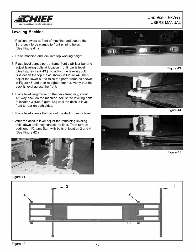
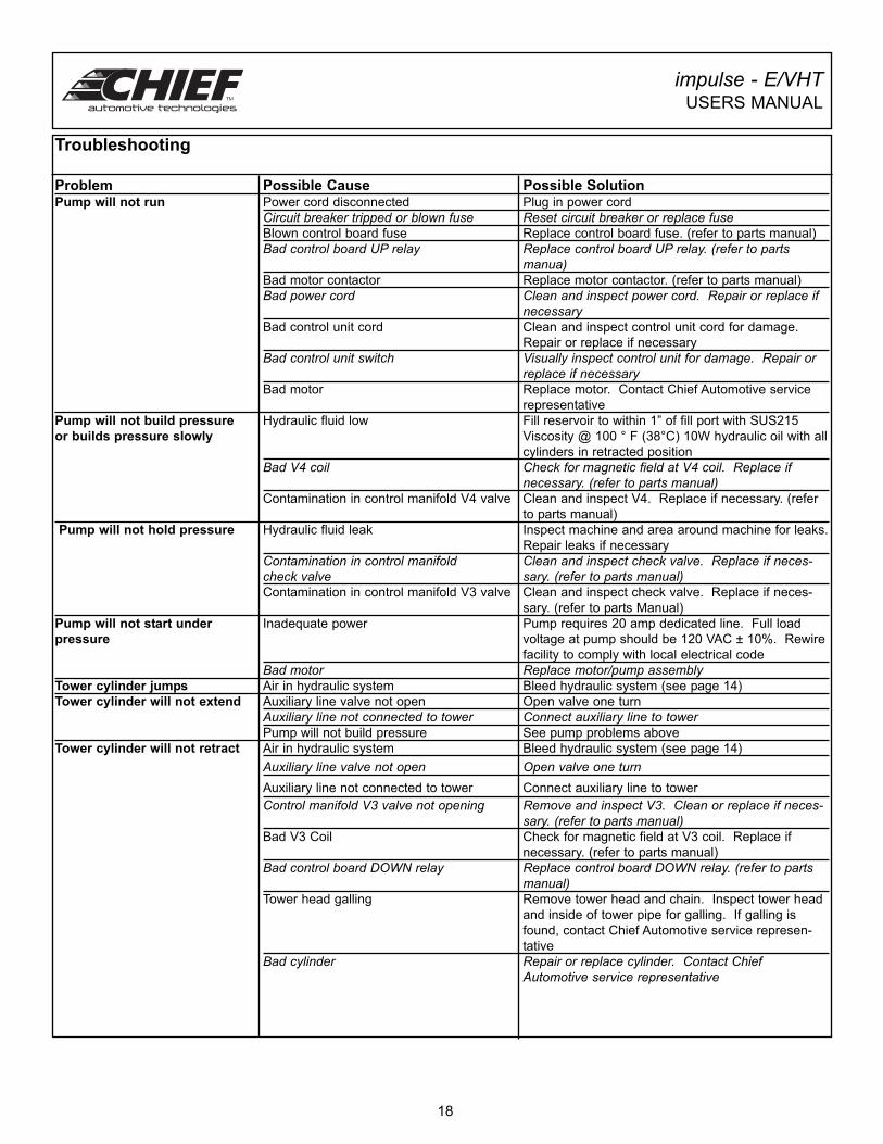
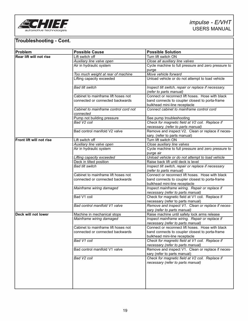
3. Place level across port-a-frame front stabilizer bar and
adjust leveling bolts at location 1 until bar is level.
(See Figures 42 & 43.) To adjust the leveling bolt,
first loosen the top nut as shown in Figure 44. Then
adjust the lower nut to raise the porta-frame as shown
in Figure 45 and then re-tighten top nut. Verify that the
deck is level across the front.
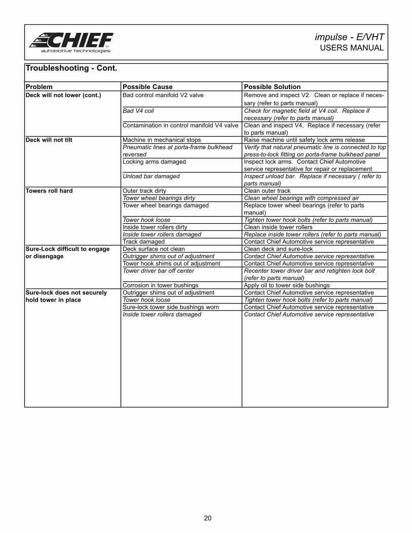
4. Place level lengthwise on the deck treadway, about
1/2 way back on the machine. Adjust the leveling bolts
at location 3 (See Figure 42.) until the deck is level
front to rear on both sides.
5. Place level across the back of the deck to verify level.
6. After the deck is level adjust the remaining leveling
bolts down until they contact the floor. Then turn an
additional 1/2 turn. Start with bolts at location 2 and 4
(See Figure 42.)
impulse - E/VHTUSERS MANUAL
17
Figure 41
Figure 43
Figure 44
Figure 45
Figure 42
13
24
Troubleshooting
Problem Possible Cause Possible SolutionPump will not run Power cord disconnected Plug in power cord
Circuit breaker tripped or blown fuse Reset circuit breaker or replace fuseBlown control board fuse Replace control board fuse. (refer to parts manual)
Bad control board UP relay Replace control board UP relay. (refer to partsmanua)
Bad motor contactor Replace motor contactor. (refer to parts manual)
Bad power cord Clean and inspect power cord. Repair or replace ifnecessary
Bad control unit cord Clean and inspect control unit cord for damage.
Repair or replace if necessary
Bad control unit switch Visually inspect control unit for damage. Repair or replace if necessary
Bad motor Replace motor. Contact Chief Automotive service
representative
Pump will not build pressure Hydraulic fluid low Fill reservoir to within 1” of fill port with SUS215
or builds pressure slowly Viscosity @ 100 ° F (38°C) 10W hydraulic oil with all
cylinders in retracted position
Bad V4 coil Check for magnetic field at V4 coil. Replace if necessary. (refer to parts manual)
Contamination in control manifold V4 valve Clean and inspect V4. Replace if necessary. (refer
to parts manual)
Pump will not hold pressure Hydraulic fluid leak Inspect machine and area around machine for leaks.
Repair leaks if necessary
Contamination in control manifold Clean and inspect check valve. Replace if neces-check valve sary. (refer to parts manual)Contamination in control manifold V3 valve Clean and inspect check valve. Replace if neces-
sary. (refer to parts Manual)
Pump will not start under Inadequate power Pump requires 20 amp dedicated line. Full load
pressure voltage at pump should be 120 VAC ± 10%. Rewire
facility to comply with local electrical code
Bad motor Replace motor/pump assemblyTower cylinder jumps Air in hydraulic system Bleed hydraulic system (see page 14)
Tower cylinder will not extend Auxiliary line valve not open Open valve one turn
Auxiliary line not connected to tower Connect auxiliary line to towerPump will not build pressure See pump problems above
Tower cylinder will not retract Air in hydraulic system Bleed hydraulic system (see page 14)
Auxiliary line valve not open Open valve one turnAuxiliary line not connected to tower Connect auxiliary line to tower
Control manifold V3 valve not opening Remove and inspect V3. Clean or replace if neces-sary. (refer to parts manual)
Bad V3 Coil Check for magnetic field at V3 coil. Replace if
necessary. (refer to parts manual)
Bad control board DOWN relay Replace control board DOWN relay. (refer to parts manual)
Tower head galling Remove tower head and chain. Inspect tower head
and inside of tower pipe for galling. If galling is
found, contact Chief Automotive service represen-
tative
Bad cylinder Repair or replace cylinder. Contact Chief Automotive service representative
impulse - E/VHTUSERS MANUAL
18
impulse - E/VHTUSERS MANUAL
19
Troubleshooting - Cont.
Problem Possible Cause Possible SolutionRear lift will not rise Lift switch off Turn lift switch ON
Auxiliary line valve open Close all auxiliary line valvesAir in hydraulic system Cycle machine to full pressure and zero pressure to
purge
Too much weight at rear of machine Move vehicle forwardLifting capacity exceeded Unload vehicle or do not attempt to load vehicle
Bad tilt switch Inspect tilt switch, repair or replace if necessary. (refer to parts manual)
Cabinet to mainframe lift hoses not Connect or reconnect lift hoses. Hose with black
connected or connected backwards band connects to coupler closest to porta-frame
bulkhead mini-line receptacle
Cabinet to mainframe control cord not Connect cabinet to mainframe control cordconnectedPump not building pressure See pump troubleshooting
Bad V2 coil Check for magnetic field at V2 coil. Replace if necessary. (refer to parts manual)
Bad control manifold V2 valve Remove and inspect V2. Clean or replace if neces-
sary. (refer to parts manual)
Front lift will not rise Lift switch off Turn lift switch ON
Auxiliary line valve open Close auxiliary line valvesAir in hydraulic system Cycle machine to full pressure and zero pressure to
purge air
Lifting capacity exceeded Unload vehicle or do not attempt to load vehicleDeck in tilted position Raise back lift until deck is level
Bad tilt switch Inspect tilt switch, repair or replace if necessary (refer to parts manual)
Cabinet to mainframe lift hoses not Connect or reconnect lift hoses. Hose with black
connected or connected backwards band connects to coupler closest to porta-frame
bulkhead mini-line receptacle
Mainframe wiring damaged Inspect mainframe wiring. Repair or replace if necessary (refer to parts manual)
Bad V1 coil Check for magnetic field at V1 coil. Replace if
necessary (refer to parts manual)
Bad control manifold V1 valve Remove and inspect V1. Clean or replace if neces-sary (refer to parts manual)
Deck will not lower Machine in mechanical stops Raise machine until safety lock arms release
Mainframe wiring damaged Inspect mainframe wiring. Repair or replace if necessary (refer to parts manual)
Cabinet to mainframe lift hoses not Connect or reconnect lift hoses. Hose with black
connected or connected backwards band connects to coupler closest to porta-frame
bulkhead mini-line receptacle
Bad V1 coil Check for magnetic field at V1 coil. Replace if necessary (refer to parts manual)
Bad control manifold V1 valve Remove and inspect V1. Clean or replace if neces-
sary (refer to parts manual)
Bad V2 coil Check for magnetic field at V2 coil. Replace if necessary (refer to parts manual)
impulse - E/VHTUSERS MANUAL
Troubleshooting - Cont.
Problem Possible Cause Possible Solution
Deck will not lower (cont.) Bad control manifold V2 valve Remove and inspect V2. Clean or replace if neces-
sary (refer to parts manual)
Bad V4 coil Check for magnetic field at V4 coil. Replace if necessary (refer to parts manual)
Contamination in control manifold V4 valve Clean and inspect V4, Replace if necessary (refer
to parts manual)
Deck will not tilt Machine in mechanical stops Raise machine until safety lock arms release
Pneumatic lines at porta-frame bulkhead Verify that natural pneumatic line is connected to topreversed press-to-lock fitting on porta-frame bulkhead panelLocking arms damaged Inspect lock arms. Contact Chief Automotive
service representative for repair or replacement
Unload bar damaged Inspect unload bar. Replace if necessary ( refer toparts manual)
Towers roll hard Outer track dirty Clean outer track
Tower wheel bearings dirty Clean wheel bearings with compressed airTower wheel bearings damaged Replace tower wheel bearings (refer to parts
manual)
Tower hook loose Tighten tower hook bolts (refer to parts manual)Inside tower rollers dirty Clean inside tower rollers
Inside tower rollers damaged Replace inside tower rollers (refer to parts manual)Track damaged Contact Chief Automotive service representative
Sure-Lock difficult to engage Deck surface not clean Clean deck and sure-lock
or disengage Outrigger shims out of adjustment Contact Chief Automotive service representativeTower hook shims out of adjustment Contact Chief Automotive service representative
Tower driver bar off center Recenter tower driver bar and retighten lock bolt (refer to parts manual)
Corrosion in tower bushings Apply oil to tower side bushings
Sure-lock does not securely Outrigger shims out of adjustment Contact Chief Automotive service representative
hold tower in place Tower hook loose Tighten tower hook bolts (refer to parts manual)Sure-lock tower side bushings worn Contact Chief Automotive service representative
Inside tower rollers damaged Contact Chief Automotive service representative
20
impulse - E/VHTUSERS MANUAL
21
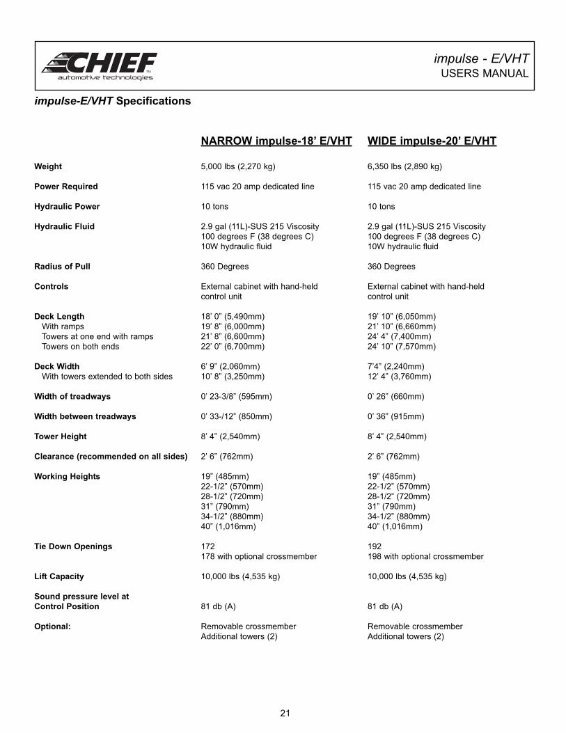
impulse-E/VHT Specifications
NARROW impulse-18’ E/VHT WIDE impulse-20’ E/VHT
Weight 5,000 lbs (2,270 kg) 6,350 lbs (2,890 kg)
Power Required 115 vac 20 amp dedicated line 115 vac 20 amp dedicated line
Hydraulic Power 10 tons 10 tons
Hydraulic Fluid 2.9 gal (11L)-SUS 215 Viscosity 2.9 gal (11L)-SUS 215 Viscosity
100 degrees F (38 degrees C) 100 degrees F (38 degrees C)
10W hydraulic fluid 10W hydraulic fluid
Radius of Pull 360 Degrees 360 Degrees
Controls External cabinet with hand-held External cabinet with hand-held
control unit control unit
Deck Length 18’ 0” (5,490mm) 19’ 10” (6,050mm)
With ramps 19’ 8” (6,000mm) 21’ 10” (6,660mm)
Towers at one end with ramps 21’ 8” (6,600mm) 24’ 4” (7,400mm)
Towers on both ends 22’ 0” (6,700mm) 24’ 10” (7,570mm)
Deck Width 6’ 9” (2,060mm) 7’4” (2,240mm)
With towers extended to both sides 10’ 8” (3,250mm) 12’ 4” (3,760mm)
Width of treadways 0’ 23-3/8” (595mm) 0’ 26” (660mm)
Width between treadways 0’ 33-/12” (850mm) 0’ 36” (915mm)
Tower Height 8’ 4” (2,540mm) 8’ 4” (2,540mm)
Clearance (recommended on all sides) 2’ 6” (762mm) 2’ 6” (762mm)
Working Heights 19” (485mm) 19” (485mm)
22-1/2” (570mm) 22-1/2” (570mm)
28-1/2” (720mm) 28-1/2” (720mm)
31” (790mm) 31” (790mm)
34-1/2” (880mm) 34-1/2” (880mm)
40” (1,016mm) 40” (1,016mm)
Tie Down Openings 172 192
178 with optional crossmember 198 with optional crossmember
Lift Capacity 10,000 lbs (4,535 kg) 10,000 lbs (4,535 kg)
Sound pressure level at
Control Position 81 db (A) 81 db (A)
Optional: Removable crossmember Removable crossmember
Additional towers (2) Additional towers (2)
996 Industrial Drive
Madison, IN 47250
Phone: 800-445-9262
Fax: 866-275-0173
www.chiefautomotive.com
Chief reserves the right to alter product specifications
and/or package components without notice.
Form I-E/VHTUM
Part No. 450428, CO7527.2, Rev. A, 1/26/10