Embed Size (px)
Citation preview
Ground Support 2013 — Y. Potvin and B. Brady (eds) © 2013 Australian Centre for Geomechanics, Perth, ISBN 978-0-9806154-7-0
Ground Support 2013, Perth, Australia 207
In situ dynamic drop testing of the MD bolt at Mt Charlotte Gold Mine
R. Carlton Kalgoorlie Consolidated Gold Mines Pty Ltd, Australia
B. Darlington Sandvik Mining, Australia
P.A. Mikula Mikula Geotechnics Pty Ltd, Australia
Abstract
The MD bolt has recently been trialled at Mt Charlotte Gold Mine. Static in situ load testing has demonstrated high anchorage capacities for the MD bolt in this rock mass, but it was not certain how the bolt would perform in dynamic conditions. Therefore a series of drop tests were conducted on bolts installed underground. This was done by suspending a one tonne mass on chains below the test bolt, and then allowing it to fall through 2.1 m before transferring kinetic energy to the bolt at the collar. A high-speed video camera was used to remotely obtain the time–displacement record for each test.
The results showed that for the test conditions in this rock mass, the MD bolt will slip along the borehole during a dynamic loading. Bolt slip ranged from 23 to 503 mm per impact, and calculated bolt forces applied to the bolt ranged from 40 to 105 kN. This testing provides confidence that the bolts do have significant dynamic capacity, and can be utilised accordingly within ground support schemes at the mine.
1 Introduction
A program of in situ dynamic testing of the Sandvik MD bolt was conducted underground at Mt Charlotte gold mine on 24 January 2013. The testing principle was based on a drop weight attached to selected rockbolts in the backs of a development drive. The test program was a joint effort between personnel from Kalgoorlie Consolidated Gold Mines (KCGM), Sandvik Mining and Construction Australia, Mikula Geotechnics and Rocktech. The test rig was developed by Rocktech at Darlot underground mine in 2010, so in this paper it is referred to as the ‘Rocktech Drop Test Rig.’
Mt Charlotte is located in Kalgoorlie, in the Eastern Goldfields of Western Australia. The geological, geotechnical and seismic environment in the mine has been documented previously (Mikula and Lee, 2000). A good understanding of the seismic hazard and the selection of appropriate ground support has been a key focus of geotechnical work at the mine. With the support of mine management, significant research work has been undertaken at the mine over many years. The current program of in situ dynamic testing was an appropriate next step to develop relevant knowledge about ground support in dynamic conditions.
There were two avenues which coincided to lead to this test program. Firstly, it was recognised that in situ dynamic ground support test data was lacking. Secondly, the rockbolt type requirements at the mine had changed and there was increased interest in moving away from resin and cement grouted bolts.
In this paper the term 'scheme' rather than 'system' is uniquely used to designate an installed collection of multiple ground support and reinforcement elements intended to work together.
2 The in situ dynamic data requirement
Dynamic ground support specifications depend on many factors, but prime among them are the size of the seismic hazard, and the capacity of nominated ground support under dynamic loading.
https://papers.acg.uwa.edu.au/p/1304_13_Mikula/
In situ dynamic drop testing of the MD bolt at Mt Charlotte Gold Mine R. Carlton et al.
208 Ground Support 2013, Perth, Australia
The size of the seismic hazard is often described by an event magnitude and its distance away from a point of interest, from which an expected peak particle velocity may be defined. From this, some method is used to define the expected demand that will be imposed on the installed ground support scheme. This is not trivial to estimate, and some of the complications of the process are described by Mikula (2012). However, these aspects are outside of the scope of this paper and are not considered further.
The capacity of a ground support scheme under dynamic loading is also difficult to specify. Obviously for confident engineering of appropriate schemes, in situ data on actual energy and load performance of different schemes under dynamic conditions is required.
Unfortunately this data is quite lacking. There is a range of published material regarding a large variety of testing, but probably none that completely represent the underground dynamic situation. It is acknowledged that the testing presented in this paper similarly does not represent the full underground dynamic situation. Some shortfalls are:
It tests individual bolts, not schemes.
It applies a single dynamic impact per test, and requires multiple tests to simulate multiple impacts over time).
It applies a vertical load, which may not be axial to the bolt.
The impact is applied externally to the bolt collar, rather than through the rock mass.
However, it is considered that it does address two important issues – it is in situ, and it is dynamic.
2.1 Issue one – in situ data
In situ testing, i.e. of ground support installed in boreholes underground, takes into account the rock mass environment and the mine support installation practices, good or bad. This is a difference compared to laboratory testing which cannot duplicate the full underground environment, and which requires some sort of simulated borehole which differs from the real one. Laboratory dynamic testing is of great value, as is clear from test output from various facilities, but that is outside the scope of this paper.
An alternative approach to obtaining in situ data is by means of blast simulation of underground dynamic loading onto ground support. The Australian Centre of Geomechanics has conducted a series of such tests in Australian mines, including a test series at Mt Charlotte (Heal and Potvin, 2007). This kind of procedure tests complete ground support schemes rather than individual elements, and may identify weak links among scheme components. However, the dynamic impact from blasts is not the same as the impact from a seismic event, and the effect of blast gases may compromise the data.
2.2 Issue two – dynamic data
Static testing of ground support is routine and essential, but there is no guarantee that dynamic and static performance is equal. Often only static data on bolts is available from suppliers, or if dynamic data is provided, it is based on laboratory testing. Some companies have their own unpublished dynamic data but that is not available to the industry in general. There is therefore an incentive to obtain dynamic data.
3 The changing rockbolt requirement at Mt Charlotte mine
Over the years, the preferred rockbolt types at Mt Charlotte have changed, and there has been increased interest in moving away from grouted bolt types, for production rather than geotechnical reasons. For many years the mine used to install and grout their own cable bolts or tendons but moved to a contractual arrangement several years ago.
The installation of any grouted ground support at Mt Charlotte usually involves delays, and causes interruptions to production and disorganisation of planning. This represents a disincentive to select grouted bolts or indeed any bolt that is not single pass.
Ground support testing
Ground Support 2013, Perth, Australia 209
Secondly, the mine previously enjoyed the use of a purpose-built rockbolting machine for resin bolt installation. This performed very well, but unfortunately the machine had to be retired several years ago. Resin bolts are now installed by the jumbo, where the installation process is less well controlled and dependent on the expertise of the jumbo operator.
Also, the mine has been encountering more issues with resin bolts, in the form of excessive loss of resin into fractured ground. The mine often conducts rehabilitation into old or remnant areas, where ground has relaxed over many years. Mechanised operations at the mine commenced in 1963, and commonly areas now being re-accessed are over 20 years old. This represents a disincentive to select resin anchored bolts.
Therefore, the mine has been considering single pass mechanical bolt options that would supply more capacity than friction bolts, but not be so stiff as to be unsuitable for dynamic conditions. The MD bolt recently became available and an installation trial was conducted at the mine on 1 August 2012. Operators commented favourably on it as the installation method differed only little from that of a friction bolt. Static proof load tests at the time showed high peak loads of 275 kN tonne.
4 The MD Bolt
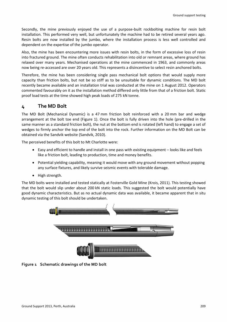
The MD Bolt (Mechanical Dynamic) is a 47 mm friction bolt reinforced with a 20 mm bar and wedge arrangement at the bolt toe end (Figure 1). Once the bolt is fully driven into the hole (pre-drilled in the same manner as a standard friction bolt), the nut at the bottom end is rotated (left hand) to engage a set of wedges to firmly anchor the top end of the bolt into the rock. Further information on the MD Bolt can be obtained via the Sandvik website (Sandvik, 2010).
The perceived benefits of this bolt to Mt Charlotte were:
Easy and efficient to handle and install in one pass with existing equipment – looks like and feels like a friction bolt, leading to production, time and money benefits.
Potential yielding capability, meaning it would move with any ground movement without popping any surface fixtures, and likely survive seismic events with tolerable damage.
High strength.
The MD bolts were installed and tested statically at Fosterville Gold Mine (Krois, 2011). This testing showed that the bolt would slip under about 200 kN static loads. This suggested the bolt would potentially have good dynamic characteristics. But as no actual dynamic data was available, it became apparent that in situ dynamic testing of this bolt should be undertaken.
Figure 1 Schematic drawings of the MD bolt
In situ dynamic drop testing of the MD bolt at Mt Charlotte Gold Mine R. Carlton et al.
210 Ground Support 2013, Perth, Australia
5 Dynamic in situ test rigs
5.1 The Rocktech Darlot drop test rig
Rocktech had designed, built and used a dynamic test rig at Darlot underground mine in 2010 to test the Garford dynamic cable bolt which was being used at that mine. The reason for testing in that case was not to determine dynamic properties, but to verify that certain installed bolts would perform dynamically. Rocktech was approached and invited to be part of the proposed testing program at Mt Charlotte.
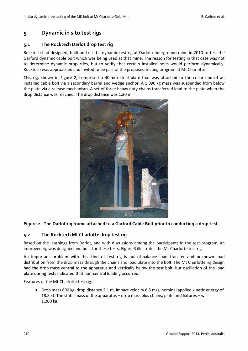
This rig, shown in Figure 2, comprised a 40 mm steel plate that was attached to the collar end of an installed cable bolt via a secondary barrel and wedge anchor. A 1,090 kg mass was suspended from below the plate via a release mechanism. A set of three heavy duty chains transferred load to the plate when the drop distance was reached. The drop distance was 1.30 m.
Figure 2 The Darlot rig frame attached to a Garford Cable Bolt prior to conducting a drop test
5.2 The Rocktech Mt Charlotte drop test rig
Based on the learnings from Darlot, and with discussions among the participants in the test program, an improved rig was designed and built for these tests. Figure 3 illustrates the Mt Charlotte test rig.
An important problem with this kind of test rig is out-of-balance load transfer and unknown load distribution from the drop mass through the chains and load plate into the bolt. The Mt Charlotte rig design had the drop mass central to the apparatus and vertically below the test bolt, but oscillation of the load plate during tests indicated that non-central loading occurred.
Features of the Mt Charlotte test rig:
Drop mass 890 kg, drop distance 2.1 m, impact velocity 6.5 m/s, nominal applied kinetic energy of 18.8 kJ. The static mass of the apparatus – drop mass plus chains, plate and fixtures – was 1,200 kg.
Ground support testing
Ground Support 2013, Perth, Australia 211
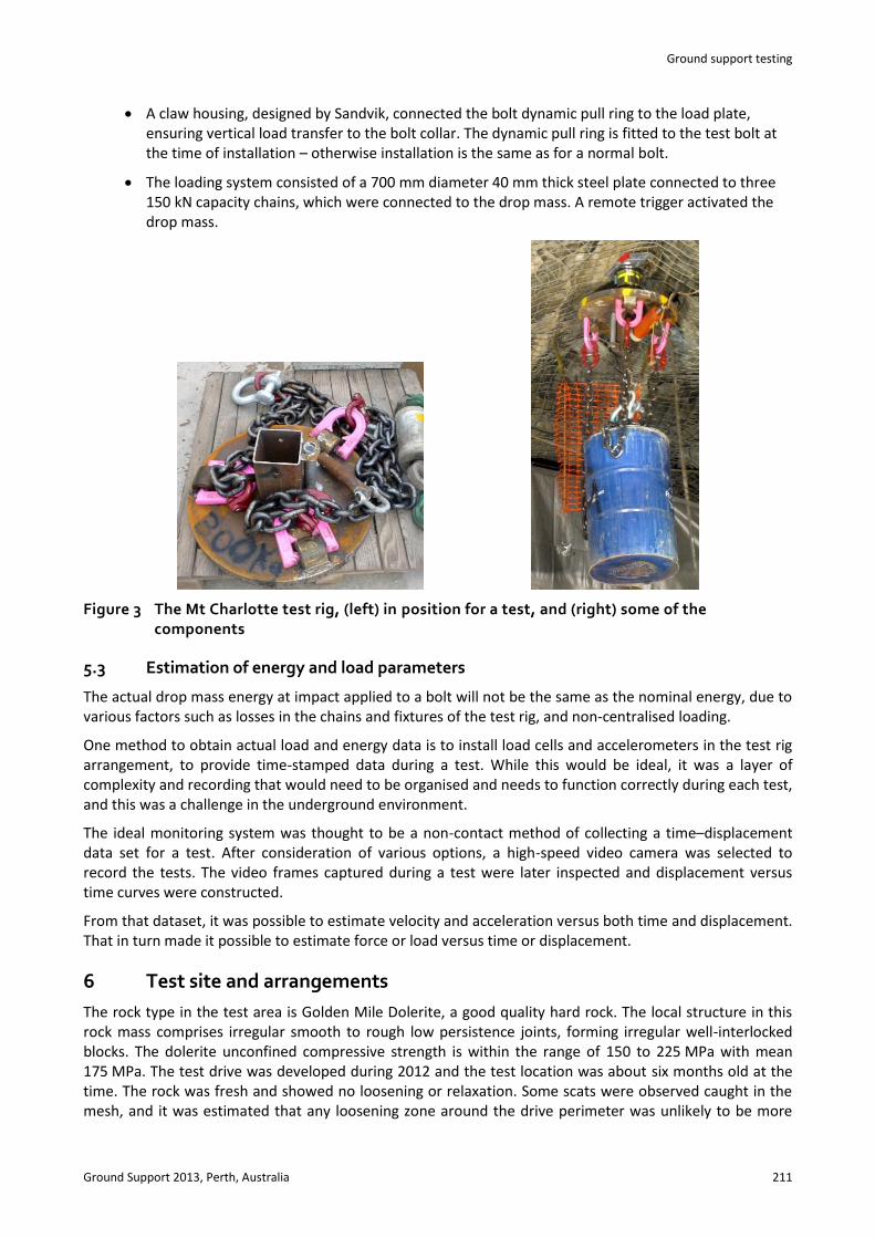
A claw housing, designed by Sandvik, connected the bolt dynamic pull ring to the load plate, ensuring vertical load transfer to the bolt collar. The dynamic pull ring is fitted to the test bolt at the time of installation – otherwise installation is the same as for a normal bolt.
The loading system consisted of a 700 mm diameter 40 mm thick steel plate connected to three 150 kN capacity chains, which were connected to the drop mass. A remote trigger activated the drop mass.
Figure 3 The Mt Charlotte test rig, (left) in position for a test, and (right) some of the components
5.3 Estimation of energy and load parameters
The actual drop mass energy at impact applied to a bolt will not be the same as the nominal energy, due to various factors such as losses in the chains and fixtures of the test rig, and non-centralised loading.
One method to obtain actual load and energy data is to install load cells and accelerometers in the test rig arrangement, to provide time-stamped data during a test. While this would be ideal, it was a layer of complexity and recording that would need to be organised and needs to function correctly during each test, and this was a challenge in the underground environment.
The ideal monitoring system was thought to be a non-contact method of collecting a time–displacement data set for a test. After consideration of various options, a high-speed video camera was selected to record the tests. The video frames captured during a test were later inspected and displacement versus time curves were constructed.
From that dataset, it was possible to estimate velocity and acceleration versus both time and displacement. That in turn made it possible to estimate force or load versus time or displacement.
6 Test site and arrangements
The rock type in the test area is Golden Mile Dolerite, a good quality hard rock. The local structure in this rock mass comprises irregular smooth to rough low persistence joints, forming irregular well-interlocked blocks. The dolerite unconfined compressive strength is within the range of 150 to 225 MPa with mean 175 MPa. The test drive was developed during 2012 and the test location was about six months old at the time. The rock was fresh and showed no loosening or relaxation. Some scats were observed caught in the mesh, and it was estimated that any loosening zone around the drive perimeter was unlikely to be more
In situ dynamic drop testing of the MD bolt at Mt Charlotte Gold Mine R. Carlton et al.
212 Ground Support 2013, Perth, Australia
than 0.1 m thick. Therefore the MD bolts were considered to have good anchorage conditions, and the contact length of the bolt sleeve with load-bearing rock was probably 2.2 m long. The test area was dry.
A group of 10 MD bolts of 2.4 m length were installed in the 1,394–1,396 intersection (with 6 m backs height) on 17 January 2013, a week before testing. Drill bit diameter used was 42 mm. The installation time per bolt was 20 to 22 sec. The installation jumbo was an Atlas Copco M2D Twin Boom. This jumbo is fitted with an anti-jamming function, so that if it approaches stall during rotation, it stops. However, the MD bolt requires rotation to stall as part of the installation procedure. This means that the Mt Charlotte equipment might not install the MD bolt correctly.
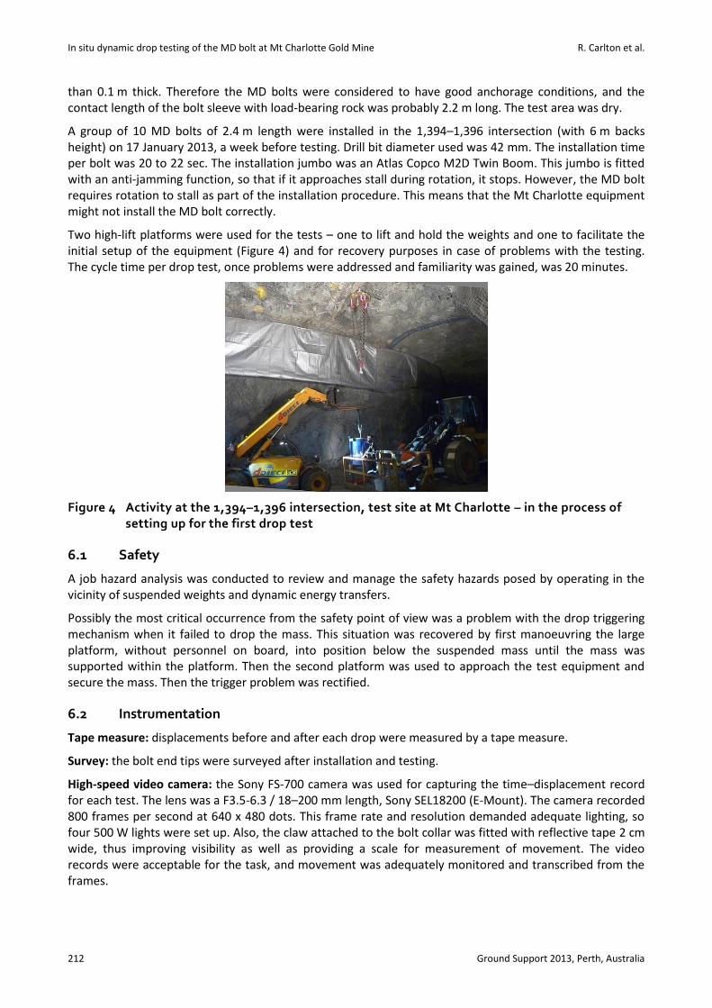
Two high-lift platforms were used for the tests – one to lift and hold the weights and one to facilitate the initial setup of the equipment (Figure 4) and for recovery purposes in case of problems with the testing. The cycle time per drop test, once problems were addressed and familiarity was gained, was 20 minutes.
Figure 4 Activity at the 1,394–1,396 intersection, test site at Mt Charlotte – in the process of setting up for the first drop test
6.1 Safety
A job hazard analysis was conducted to review and manage the safety hazards posed by operating in the vicinity of suspended weights and dynamic energy transfers.
Possibly the most critical occurrence from the safety point of view was a problem with the drop triggering mechanism when it failed to drop the mass. This situation was recovered by first manoeuvring the large platform, without personnel on board, into position below the suspended mass until the mass was supported within the platform. Then the second platform was used to approach the test equipment and secure the mass. Then the trigger problem was rectified.
6.2 Instrumentation
Tape measure: displacements before and after each drop were measured by a tape measure.
Survey: the bolt end tips were surveyed after installation and testing.
High-speed video camera: the Sony FS-700 camera was used for capturing the time–displacement record for each test. The lens was a F3.5-6.3 / 18–200 mm length, Sony SEL18200 (E-Mount). The camera recorded 800 frames per second at 640 x 480 dots. This frame rate and resolution demanded adequate lighting, so four 500 W lights were set up. Also, the claw attached to the bolt collar was fitted with reflective tape 2 cm wide, thus improving visibility as well as providing a scale for measurement of movement. The video records were acceptable for the task, and movement was adequately monitored and transcribed from the frames.
Ground support testing
Ground Support 2013, Perth, Australia 213
The camera was mounted on a tripod, and was about 4 m lower than the claw, so the video view was an angled view looking up at 25° above horizontal. Therefore, apparent vertical distances on the claw were foreshortened. But the reflective tape was equally foreshortened, so distances measured proportionally to the reflective tape were valid.
The camera had a continuous recording function into a circular buffer capable of storing 23 seconds of video at the selected frame rate and resolution. The camera had a post-event trigger function, so that the video capture could be performed a few seconds after the test, rather than trying to initiate capture at the moment of fall.
The video instrumentation recorded time–displacement data at the claw attached to the bolt collar. Bolt collar performance was the net performance taking all loading influences into account (such as any chain losses or any out of balance effects). The major difference between claw and bolt movement was rebound in the claw that caused it to momentarily separate off from the bolt collar.
The method of analysis was to overlay two frames in suitable software, making one frame semi-transparent so that the movement could be manually measured. Analysing every fifth frame was adequate (providing a good resolution of results, and suitable speed of playback), so for future tests the frame rate per second can perhaps be reduced from 800 fps to say 500 fps. The video data was used to calculate (1) displacement versus time, (2) deceleration amount, time, and distance, and (3) static force equivalents.
7 Test program
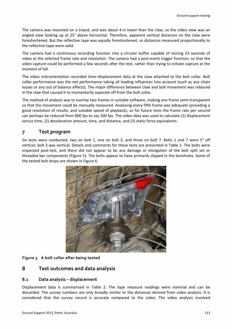
Six tests were conducted, two on bolt 1, one on bolt 3, and three on bolt 7. Bolts 1 and 7 were 5° off vertical; bolt 3 was vertical. Details and comments for these tests are presented in Table 1. The bolts were inspected post-test, and there did not appear to be any damage or elongation of the bolt split set or threaded bar components (Figure 5). The bolts appear to have primarily slipped in the boreholes. Some of the tested bolt drops are shown in Figure 6.
Figure 5 A bolt collar after being tested
8 Test outcomes and data analysis
8.1 Data analysis – displacement
Displacement data is summarised in Table 2. The tape measure readings were nominal and can be discarded. The survey numbers are only broadly similar to the distances derived from video analysis. It is considered that the survey record is accurate compared to the video. The video analysis involved
In situ dynamic drop testing of the MD bolt at Mt Charlotte Gold Mine R. Carlton et al.
214 Ground Support 2013, Perth, Australia
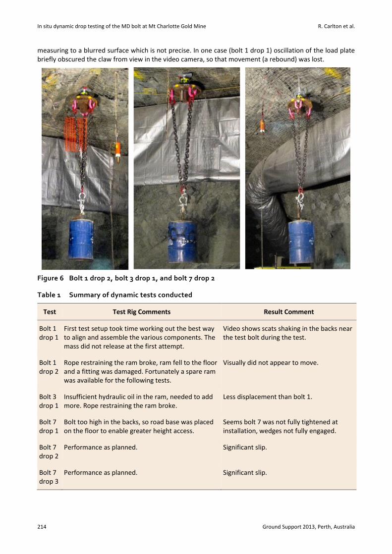
measuring to a blurred surface which is not precise. In one case (bolt 1 drop 1) oscillation of the load plate briefly obscured the claw from view in the video camera, so that movement (a rebound) was lost.
Figure 6 Bolt 1 drop 2, bolt 3 drop 1, and bolt 7 drop 2
Table 1 Summary of dynamic tests conducted
Test Test Rig Comments Result Comment
Bolt 1 drop 1
First test setup took time working out the best way to align and assemble the various components. The mass did not release at the first attempt.
Video shows scats shaking in the backs near the test bolt during the test.
Bolt 1 drop 2
Rope restraining the ram broke, ram fell to the floor and a fitting was damaged. Fortunately a spare ram was available for the following tests.
Visually did not appear to move.
Bolt 3 drop 1
Insufficient hydraulic oil in the ram, needed to add more. Rope restraining the ram broke.
Less displacement than bolt 1.
Bolt 7 drop 1
Bolt too high in the backs, so road base was placed on the floor to enable greater height access.
Seems bolt 7 was not fully tightened at installation, wedges not fully engaged.
Bolt 7 drop 2
Performance as planned. Significant slip.
Bolt 7 drop 3
Performance as planned. Significant slip.
Ground support testing
Ground Support 2013, Perth, Australia 215
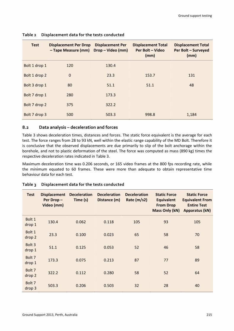
Table 2 Displacement data for the tests conducted
Test Displacement Per Drop – Tape Measure (mm)
Displacement Per Drop – Video (mm)
Displacement Total Per Bolt – Video
(mm)
Displacement Total Per Bolt – Surveyed
(mm)
Bolt 1 drop 1 120 130.4
Bolt 1 drop 2 0 23.3 153.7 131
Bolt 3 drop 1 80 51.1 51.1 48
Bolt 7 drop 1 280 173.3
Bolt 7 drop 2 375 322.2
Bolt 7 drop 3 500 503.3 998.8 1,184
8.2 Data analysis – deceleration and forces
Table 3 shows deceleration times, distances and forces. The static force equivalent is the average for each test. The force ranges from 28 to 93 kN, well within the elastic range capability of the MD Bolt. Therefore it is conclusive that the observed displacements are due primarily to slip of the bolt anchorage within the borehole, and not to plastic deformation of the steel. The force was computed as mass (890 kg) times the respective deceleration rates indicated in Table 3.
Maximum deceleration time was 0.206 seconds, or 165 video frames at the 800 fps recording rate, while the minimum equated to 60 frames. These were more than adequate to obtain representative time behaviour data for each test.
Table 3 Displacement data for the tests conducted
Test Displacement Per Drop –
Video (mm)
Deceleration Time (s)
Deceleration Distance (m)
Deceleration Rate (m/s2)
Static Force Equivalent From Drop
Mass Only (kN)
Static Force Equivalent From
Entire Test Apparatus (kN)
Bolt 1 drop 1
130.4 0.062 0.118 105 93 105
Bolt 1 drop 2
23.3 0.100 0.023 65 58 70
Bolt 3 drop 1
51.1 0.125 0.053 52 46 58
Bolt 7 drop 1
173.3 0.075 0.213 87 77 89
Bolt 7 drop 2
322.2 0.112 0.280 58 52 64
Bolt 7 drop 3
503.3 0.206 0.503 32 28 40
In situ dynamic drop testing of the MD bolt at Mt Charlotte Gold Mine R. Carlton et al.
216 Ground Support 2013, Perth, Australia
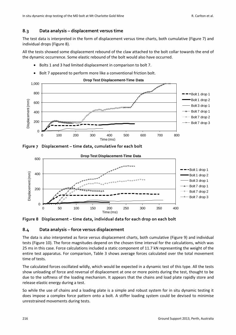
8.3 Data analysis – displacement versus time
The test data is interpreted in the form of displacement versus time charts, both cumulative (Figure 7) and individual drops (Figure 8).
All the tests showed some displacement rebound of the claw attached to the bolt collar towards the end of the dynamic occurrence. Some elastic rebound of the bolt would also have occurred.
Bolts 1 and 3 had limited displacement in comparison to bolt 7.
Bolt 7 appeared to perform more like a conventional friction bolt.
Figure 7 Displacement – time data, cumulative for each bolt
Figure 8 Displacement – time data, individual data for each drop on each bolt
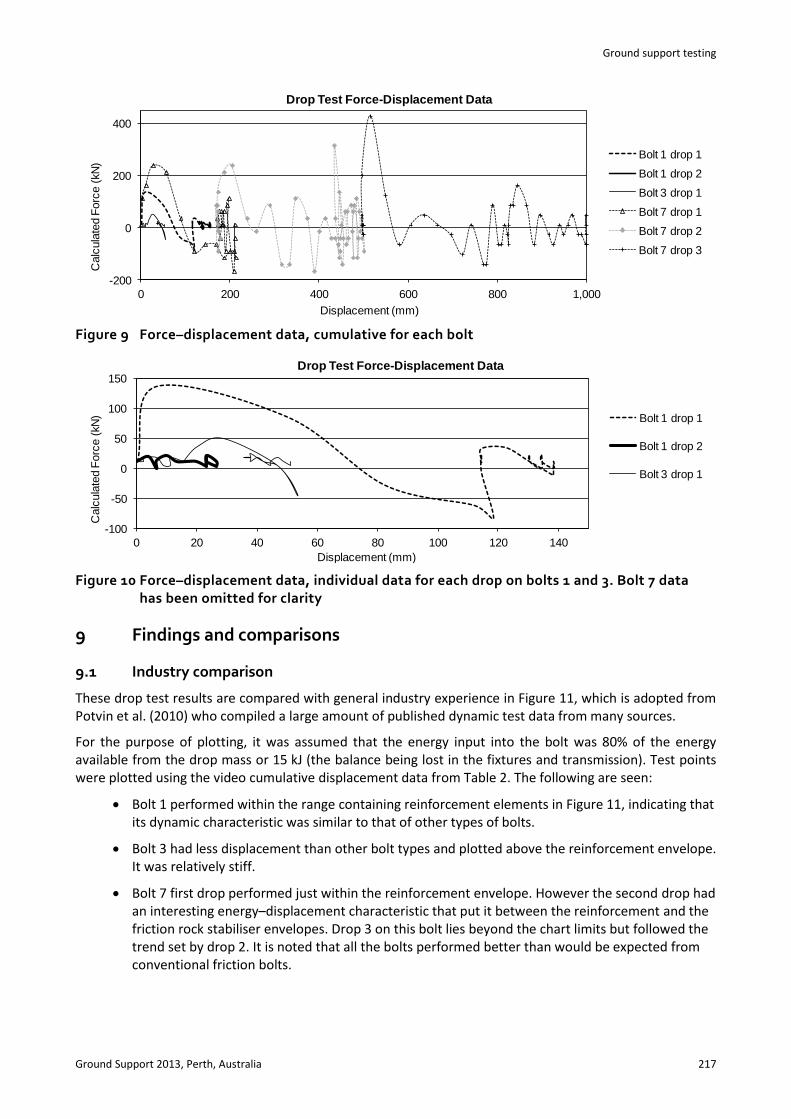
8.4 Data analysis – force versus displacement
The data is also interpreted as force versus displacement charts, both cumulative (Figure 9) and individual tests (Figure 10). The force magnitudes depend on the chosen time interval for the calculations, which was 25 ms in this case. Force calculations included a static component of 11.7 kN representing the weight of the entire test apparatus. For comparison, Table 3 shows average forces calculated over the total movement time of tests.
The calculated forces oscillated wildly, which would be expected in a dynamic test of this type. All the tests show unloading of force and reversal of displacement at one or more points during the test, thought to be due to the softness of the loading mechanism. It appears that the chains and load plate rapidly store and release elastic energy during a test.
So while the use of chains and a loading plate is a simple and robust system for in situ dynamic testing it does impose a complex force pattern onto a bolt. A stiffer loading system could be devised to minimise unrestrained movements during tests.
0
200
400
600
800
1,000
0 100 200 300 400 500 600 700 800
Dis
pla
cem
ent (
mm
)
Time (ms)
Drop Test Displacement-Time Data
Bolt 1 drop 1
Bolt 1 drop 2
Bolt 3 drop 1
Bolt 7 drop 1
Bolt 7 drop 2
Bolt 7 drop 3
0
200
400
600
0 50 100 150 200 250 300 350 400
Dis
pla
cem
ent (
mm
)
Time (ms)
Drop Test Displacement-Time Data
Bolt 1 drop 1
Bolt 1 drop 2
Bolt 3 drop 1
Bolt 7 drop 1
Bolt 7 drop 2
Bolt 7 drop 3
Ground support testing
Ground Support 2013, Perth, Australia 217
Figure 9 Force–displacement data, cumulative for each bolt
Figure 10 Force–displacement data, individual data for each drop on bolts 1 and 3. Bolt 7 data has been omitted for clarity
9 Findings and comparisons
9.1 Industry comparison
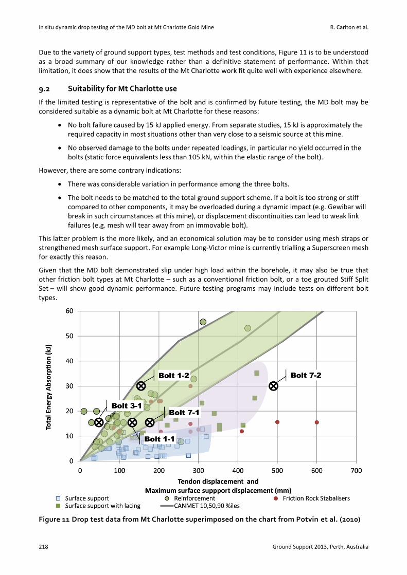
These drop test results are compared with general industry experience in Figure 11, which is adopted from Potvin et al. (2010) who compiled a large amount of published dynamic test data from many sources.
For the purpose of plotting, it was assumed that the energy input into the bolt was 80% of the energy available from the drop mass or 15 kJ (the balance being lost in the fixtures and transmission). Test points were plotted using the video cumulative displacement data from Table 2. The following are seen:
Bolt 1 performed within the range containing reinforcement elements in Figure 11, indicating that its dynamic characteristic was similar to that of other types of bolts.
Bolt 3 had less displacement than other bolt types and plotted above the reinforcement envelope. It was relatively stiff.
Bolt 7 first drop performed just within the reinforcement envelope. However the second drop had an interesting energy–displacement characteristic that put it between the reinforcement and the friction rock stabiliser envelopes. Drop 3 on this bolt lies beyond the chart limits but followed the trend set by drop 2. It is noted that all the bolts performed better than would be expected from conventional friction bolts.
-200
0
200
400
0 200 400 600 800 1,000
Calc
ula
ted F
orc
e (
kN
)
Displacement (mm)
Drop Test Force-Displacement Data
Bolt 1 drop 1
Bolt 1 drop 2
Bolt 3 drop 1
Bolt 7 drop 1
Bolt 7 drop 2
Bolt 7 drop 3
-100
-50
0
50
100
150
0 20 40 60 80 100 120 140
Calc
ula
ted F
orc
e (
kN)
Displacement (mm)
Drop Test Force-Displacement Data
Bolt 1 drop 1
Bolt 1 drop 2
Bolt 3 drop 1
In situ dynamic drop testing of the MD bolt at Mt Charlotte Gold Mine R. Carlton et al.
218 Ground Support 2013, Perth, Australia
Due to the variety of ground support types, test methods and test conditions, Figure 11 is to be understood as a broad summary of our knowledge rather than a definitive statement of performance. Within that limitation, it does show that the results of the Mt Charlotte work fit quite well with experience elsewhere.
9.2 Suitability for Mt Charlotte use
If the limited testing is representative of the bolt and is confirmed by future testing, the MD bolt may be considered suitable as a dynamic bolt at Mt Charlotte for these reasons:
No bolt failure caused by 15 kJ applied energy. From separate studies, 15 kJ is approximately the required capacity in most situations other than very close to a seismic source at this mine.
No observed damage to the bolts under repeated loadings, in particular no yield occurred in the bolts (static force equivalents less than 105 kN, within the elastic range of the bolt).
However, there are some contrary indications:
There was considerable variation in performance among the three bolts.
The bolt needs to be matched to the total ground support scheme. If a bolt is too strong or stiff compared to other components, it may be overloaded during a dynamic impact (e.g. Gewibar will break in such circumstances at this mine), or displacement discontinuities can lead to weak link failures (e.g. mesh will tear away from an immovable bolt).
This latter problem is the more likely, and an economical solution may be to consider using mesh straps or strengthened mesh surface support. For example Long-Victor mine is currently trialling a Superscreen mesh for exactly this reason.
Given that the MD bolt demonstrated slip under high load within the borehole, it may also be true that other friction bolt types at Mt Charlotte – such as a conventional friction bolt, or a toe grouted Stiff Split Set – will show good dynamic performance. Future testing programs may include tests on different bolt types.
Figure 11 Drop test data from Mt Charlotte superimposed on the chart from Potvin et al. (2010)
Ground support testing
Ground Support 2013, Perth, Australia 219
9.3 Future test rig
Based on Mt Charlotte experience, design improvements in any future rig could include:
An improved trigger drop system.
An improved claw arrangement.
A drop slide rather than chains, to remove irregularities associated with chains, with a means of restraining the rebound from a drop mass.
A faster reset method so that successive tests can be conducted much more quickly, reducing the cost and personnel requirements of conducting these kinds of tests.
A means of adapting the rig for testing of surface support (mesh and fibrecrete).
10 Conclusions
This work shows that it is within mine site capability to organise and conduct dynamic drop testing of bolts. This testing is significantly more complex to conduct and analyse compared to static proof load testing. With current technology, in situ testing cannot be viewed as a routine procedure, but rather as a proof of concept as to whether a particular bolt will match the dynamic expectations within a mine.
Overall the testing was a success as the MD Bolt has been confirmed as having dynamic capabilities by virtue of being able to slip within the borehole. The in situ testing provided data on actual underground performance of bolts, which will improve the confidence in engineering calculations regarding ground support schemes in dynamic conditions.
Acknowledgements
Thank you to all who assisted in this project. The testing on the day was the combined effort of the authors as well as Peter Bagley, Josh Duke, Brad George, Scott Ferguson, Kai Han (KCGM), Wayne Billam, Matty Hawkes (Rocktech), and Justyna Czekaj (Sandvik). Thank you also to Mietek Rataj (bolt designer) and James Langdon (instrumentation advice) and Matty Hawkes (test rig ideas, fabrication of parts and continual help in the lead up to the testing day) and finally to Vic Simpson and Anthony Gleeson (KCGM) for giving their approval for the testing to go ahead.
References
Heal, D. and Potvin, Y. (2007) In-situ dynamic testing of ground support using simulated rockbursts, in Proceedings Fourth International Seminar on Deep and High Stress Mining (Deep Mining 07), Y. Potvin (ed), 7‒9 November 2007, Perth, Australia, Australian Centre for Geomechanics, Perth, pp. 373–394.
Krois, L. (2011) Maximum innovation, safety and productivity – the MD Bolt introduction at the Fosterville Gold Mine, in Forum notes ACG international Forum on Safe and Rapid Mining Productivity Development, 24 March 2011, Canberra, Australia, Australian Centre for Geomechanics, Perth, CD-Rom only.
Mikula, P.A. (2012) Progress with empirical performance charting for confident selection of ground support in seismic conditions, in Proceedings Sixth International Seminar on Deep and High Stress Mining (Deep Mining 2012), Y. Potvin (ed), 28–30 March 2012, Perth, Australia, Australian Centre for Geomechanics, Perth, pp. 71–89. Also in Mining Technology: Section A, Maney Publishing, Vol. 121, Number 4, 2012, pp. 192–203.
Mikula, P.A. and Lee, M.F. (2000) Bulk low-grade mining at Mt Charlotte Mine, in Proceedings MassMin 2000, G. Chitombo (ed), 29 October to 2 November 2000, Brisbane, Australia, Australian Institute of Mining and Metallurgy, Melbourne, pp. 623−635.
Potvin, Y., Wesseloo, J. and Heal, D. (2010) An interpretation of ground support capacity submitted to dynamic loading, in Proceedings Fifth International Seminar on Deep and High Stress Mining (Deep Mining 2010), M. Van Sint Jan and Y. Potvin (eds), 6–8 October 2010, Santiago, Chile, Australian Centre for Geomechanics, Perth, pp. 251–272. Also in Mining Technology, Vol. 119 (4), pp. 1–13.
Sandvik (2010) Sandvik Mining and Construction Australia, viewed 29 January 2013, www.miningandconstruction.sandvik.com.au.

In situ dynamic drop testing of the MD bolt at Mt Charlotte Gold Mine R. Carlton et al.
220 Ground Support 2013, Perth, Australia