Embed Size (px)
Citation preview
Systems Configurations . . . . . . . . 2
Safety . . . . . . . . . . . . . . . . . . . . 4
Getting Acquainted . . . . . . . . . . . 4
Setup . . . . . . . . . . . . . . . . . . . . 5
Pro II Fence Installation . . . . . . . 6
Wonder Fence Installation . . . . . . . 8
Shop Stop . . . . . . . . . . . . . . . . . 10
Operation . . . . . . . . . . . . . . . . . 12
Applications . . . . . . . . . . . . . . . . 14
Adjustments . . . . . . . . . . . . . . . . 14
Auto Centering Scale . . . . . . . . . . 15
Warranty . . . . . . . . . . . . . . . . . . 16
COntentS
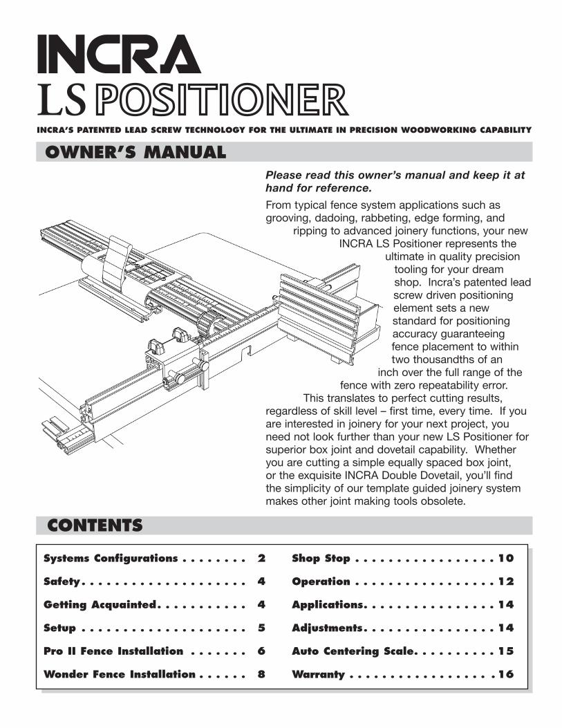
Please read this owner’s manual and keep it at hand for reference.
From typical fence system applications such as grooving, dadoing, rabbeting, edge forming, and
ripping to advanced joinery functions, your new INCRA LS Positioner represents the
ultimate in quality precision tooling for your dream shop. Incra’s patented lead screw driven positioning element sets a new standard for positioning accuracy guaranteeing fence placement to within two thousandths of an
inch over the full range of the fence with zero repeatability error.
This translates to perfect cutting results, regardless of skill level – first time, every time. If you are interested in joinery for your next project, you need not look further than your new LS Positioner for superior box joint and dovetail capability. Whether you are cutting a simple equally spaced box joint, or the exquisite INCRA Double Dovetail, you’ll find the simplicity of our template guided joinery system makes other joint making tools obsolete.
OWner’S MAnuAl
INCRAInCrA’S PAtenteD leAD SCreW teCHnOlOGY FOr tHe ultIMAte In PreCISIOn WOODWOrKInG CAPABIlItY
lS P
osi
tioner
“Sta
ndard
Syst
em
”
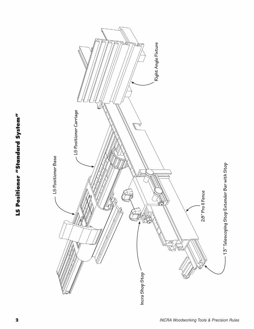
LS P
osit
ione
r Bas
e LS P
osit
ione
r Car
riage
Rig
ht A
ngle
Fix
ture
28
” Pro
II F
ence
Incr
a S
hop
Sto
p
2 INCRAWoodworkingTools&PrecisionRules
13
” Tel
esco
ping
Sto
p Ex
tend
er B
ar w
ith
Sto
p
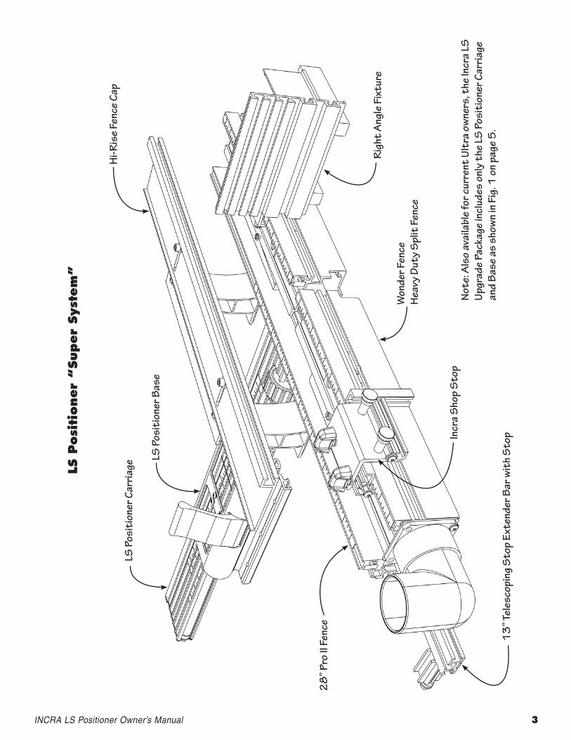
lS P
osi
tioner
“Super
Syst
em
”
LS P
osit
ione
r Car
riage
LS P
osit
ione
r Bas
e
Hi-R
ise
Fenc
e Ca
p
Rig
ht A
ngle
Fix
ture
Won
der F
ence
Hea
vy D
uty
Spl
it F
ence
Incr
a S
hop
Sto
p
13
” Tel
esco
ping
Sto
p Ex
tend
er B
ar w
ith
Sto
p
28
” Pro
II F
ence
Not
e: A
lso
avai
labl
e fo
r cur
rent
Ult
ra o
wne
rs, t
he In
cra
LS
Upgr
ade
Pack
age
incl
udes
onl
y th
e LS
Pos
itio
ner C
arria
ge
and
Base
as
show
n in
Fig
. 1 o
n pa
ge 5
.
INCRALSPositionerOwner’sManual 3
4 INCRAWoodworkingTools&PrecisionRules
Before using the INCRA LS Positioner, read and follow all of the instructions and safety information in this manual.
When using the INCRA LS Positioner in conjunction with any other tool, first read and follow all instructions and safety information in that tool’s owner’s manual.
When mounted to a table surface, make sure that all of the mounting screws are securely tightened and the INCRA LS Positioner is firmly held in place.
Always turn off the power and make sure that the bit or blade is fully stationary before moving the INCRA LS Positioner to any new setting.
Always keep both hands behind the fence when moving the INCRA LS Positioner to a new setting.
Before making a cut, always make sure that the carriage clamp is fully engaged and the fence is securely locked in place.
When using the INCRA LS Positioner with other tools, make sure that all safety guards and other safety equipment supplied by the manufacturer of that tool are securely in place and functional. Never let the INCRA LS Positioner interfere with another tool’s safety equipment.
Use appropriate safety devices. Keep hands clear of the bit or blade. Always use a push stick, rubber soled push block, or other safety device to keep your hands safely away from the cutting tool.
Wear safety glasses, hearing protection and follow all normal shop safety practices.
DO NOT alter or modify the INCRA LS Positioner in an attempt to use it with non-INCRA accessories.
Never let the bit or blade come into contact with any part of the INCRA LS Positioner, INCRA Shop Stop, or INCRA Right Angle Fixture.
SAFetY
GettInG ACquAInteD
Important safety instructions for using the InCrA lS Positioner
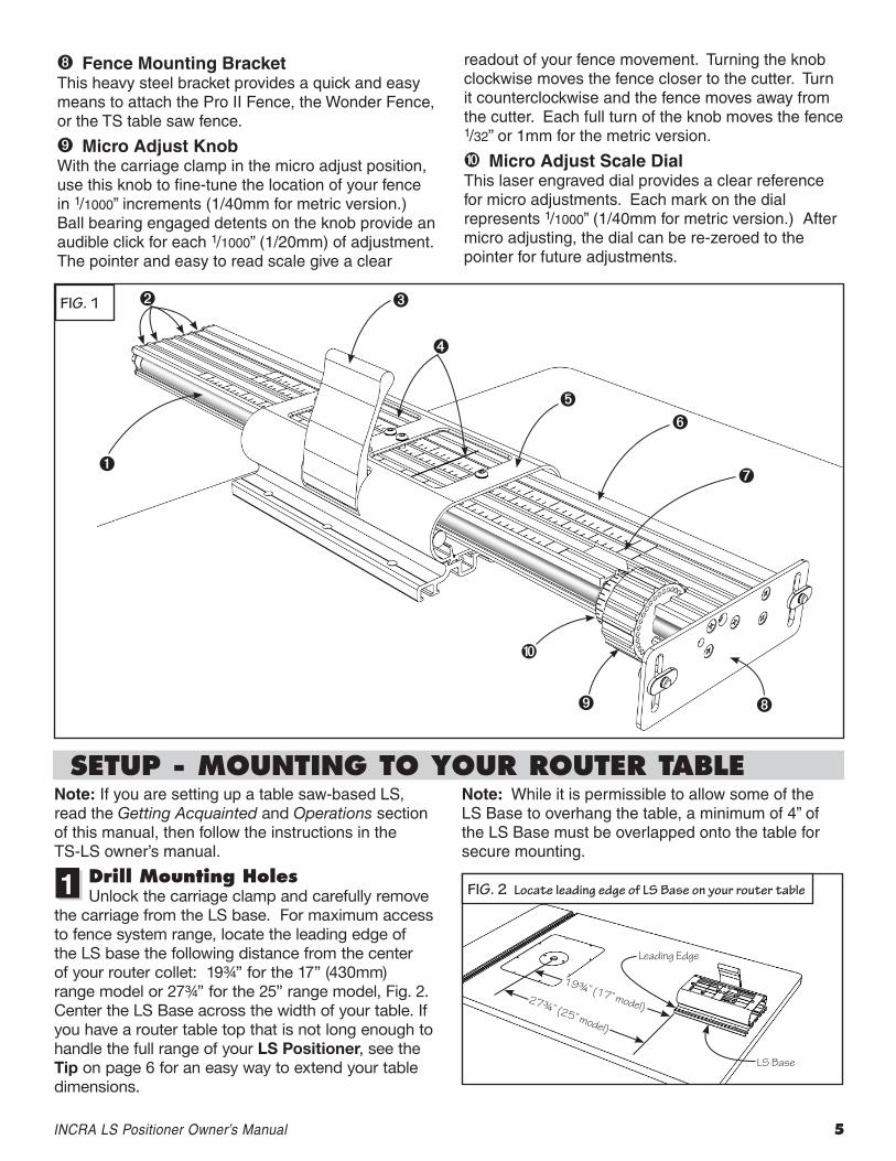
Before setting up and using your new INCRA LS Positioner, take a few moments to become better acquainted with the tool by reviewing the following component descriptions and the illustration in Fig. 1.
Lead Screw Positioning ElementThe LS Positioner obtains its great accuracy and repeatability from the precision lead screw, which positions the fence in exact increments of 1/32” (1mm metric version.)
Auxiliary Scale SlotsFour auxiliary scale slots are provided to allow additional setups and cutting operations to take place without altering the primary scale position. Simply slide the supplied 1/32” or 1mm “floating” scale into position as needed for reference. The friction fit holds the scales securely during cutting operations. These extra slots are great for advanced joinery using the INCRA templates. You can even leave your most frequently used joinery templates from the optional INCRA Master Reference Guide & Template Library permanently installed.
Three-Position Carriage ClampBy pushing the carriage clamp down into the “unlocked” position, the carriage is free to glide to the next setting. Pull the clamp up to the center position for micro adjusting. Pull the clamp up to the final position and the carriage is locked solidly in place.
Hairline Cursor and View Windows The large hairline cursor and view windows provide a clear visual reference of the fence location and span the width of the carriage top and all five scale slots. The factory placement of the cursor can be moved to the rear view window location for use on smaller router tables.
LS BaseThe LS Base contains the threaded segment that engages with and functions to locate the carriage. It also houses the three-position carriage clamp, the hairline cursor, and view windows.
Carriage The reinforced square tube design of the carriage provides the ultimate in strength and support for your fence. It supports the lead screw positioning element and the micro adjust knob.
Stainless Steel Primary ScaleAfter setting up your INCRA LS Positioner and “zeroing” to the bit or blade, position this scale to read 0” under the hairline cursor. Use this scale as the primary source for readout of fence to bit or blade distance.
INCRALSPositionerOwner’sManual 5
Fence Mounting BracketThis heavy steel bracket provides a quick and easy means to attach the Pro II Fence, the Wonder Fence, or the TS table saw fence.
Micro Adjust KnobWith the carriage clamp in the micro adjust position, use this knob to fine-tune the location of your fence in 1/1000” increments (1/40mm for metric version.) Ball bearing engaged detents on the knob provide an audible click for each 1/1000” (1/20mm) of adjustment. The pointer and easy to read scale give a clear
readout of your fence movement. Turning the knob clockwise moves the fence closer to the cutter. Turn it counterclockwise and the fence moves away from the cutter. Each full turn of the knob moves the fence 1/32” or 1mm for the metric version.
Micro Adjust Scale DialThis laser engraved dial provides a clear reference for micro adjustments. Each mark on the dial represents 1/1000” (1/40mm for metric version.) After micro adjusting, the dial can be re-zeroed to the pointer for future adjustments.
FIg. 1
SetuP - MOuntInG tO YOur rOuter tABleNote: If you are setting up a table saw-based LS, read the Getting Acquainted and Operations section of this manual, then follow the instructions in the TS-LS owner’s manual.
Drill Mounting HolesUnlock the carriage clamp and carefully remove
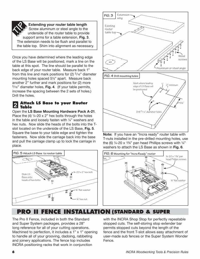
the carriage from the LS base. For maximum access to fence system range, locate the leading edge of the LS base the following distance from the center of your router collet: 19¾” for the 17” (430mm) range model or 27¾” for the 25” range model, Fig. 2. Center the LS Base across the width of your table. If you have a router table top that is not long enough to handle the full range of your LS Positioner, see the Tip on page 6 for an easy way to extend your table dimensions.
Note: While it is permissible to allow some of the LS Base to overhang the table, a minimum of 4” of the LS Base must be overlapped onto the table for secure mounting.
1 FIg. 2 Locate leading edge of LS Base on your router table
19¾” (17” model)27¾” (25” model)
Leading Edge
LS Base
6 INCRAWoodworkingTools&PrecisionRules
Once you have determined where the leading edge of the LS Base will be positioned, mark a line on the table at this spot. The line should be parallel to the back edge of your router table. Measure back 1” from this line and mark positions for (2) 5/16” diameter mounting holes spaced 5½” apart. Measure back another 2” further and mark positions for (2) more 5/16” diameter holes, Fig. 4. (If your table permits, increase the spacing between the 2 sets of holes.) Drill the holes.
Attach lS Base to your router table
Open the LS Base Mounting Hardware Pack A-21. Place the (4) ¼-20 x 2” hex bolts through the holes in the table and loosely fasten with ¼” washers and hex nuts. Now slide the heads of the bolts into the T-slot located on the underside of the LS Base, Fig. 5. Square the base to your table edge and tighten the fasteners. Now slide the carriage back into the base and pull the carriage clamp up to lock the carriage in place.
FIg. 3 Extension wing
2
Extending your router table lengthScrew aluminum or steel angle to the underside of the router table to provide
support arms for a table extension, Fig. 3. The extension needs to be flush and parallel to the table top. Shim into alignment as necessary.
Existing router table top
Wood screws
Aluminum or steel angle
5½”
Drill 5/16” diameter holes
Mark where leading edge of LS Base will be positioned
1” 2” minimum
Slide LS Base onto heads of hex bolts
¼-20 x 2” hex bolt
¼” flat washer
¼” hex nut
¼-20 x 1¾” pan head Phillips screws
¼” flat washer
PrO II FenCe InStAllAtIOn (StAnDArD & SuPer
Note: If you have an “Incra ready” router table with T-nuts installed in the pre-drilled mounting holes, use the (6) ¼-20 x 1¾” pan head Phillips screws with ¼” washers to attach the LS Base as shown in Fig. 6.
The Pro II Fence, included in both the Standard and Super System packages, provides a 28” long reference for all of your cutting operations. Machined to perfection, it includes a 1” x 1” opening to handle all of your grooving, dadoing, rabbeting and joinery applications. The fence top includes INCRA positioning racks that work in conjunction
with the INCRA Shop Stop for perfectly repeatable stopped cuts. The self-storing stop extender bar permits stopped cuts beyond the length of the fence and the front T-slot allows easy attachment of user-made sub fences or the Super System Wonder Fence.
FIg. 6 Mounting for “Incra Ready” router
FIg. 4 Drill mounting holes
FIg. 5 Attach LS Base to router table
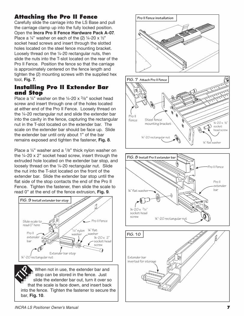
Pro II Fence installationAttaching the Pro II FenceCarefully slide the carriage into the LS Base and pull the carriage clamp up into the fully locked position. Open the Incra Pro II Fence Hardware Pack A-07. Place a ¼” washer on each of the (2) ¼-20 x ½” socket head screws and insert through the slotted holes located on the steel fence mounting bracket. Loosely thread on the ¼-20 rectangular nuts, then slide the nuts into the T-slot located on the rear of the Pro II Fence. Position the fence so that the carriage is approximately centered on the fence length and tighten the (2) mounting screws with the supplied hex tool, Fig. 7.
Installing Pro II extender Bar and StopPlace a ¼” washer on the ¼-20 x 3/8” socket head screw and insert through one of the holes located at either end of the Pro II Fence. Loosely thread on the ¼-20 rectangular nut and slide the extender bar into the cavity in the fence, capturing the rectangular nut in the T-slot located on the extender bar. The scale on the extender bar should be face up. Slide the extender bar until only about 1” of the bar remains exposed and tighten the fastener, Fig. 8. Place a ¼” washer and a 1/8” thick nylon washer on the ¼-20 x 2” socket head screw, insert through the extruded hole located on the extender bar stop, and loosely thread on the ¼-20 rectangular nut. Slide the nut into the T-slot located on the front of the extender bar. Slide the extender bar stop until the flat side of the stop contacts the end of the Pro II Fence. Tighten the fastener, then slide the scale to read 0” at the end of the fence extrusion, Fig. 9.
FIg. 7 Attach Pro II Fence
Pro II Fence Steel fence
mounting bracket ¼-20 x ½” socket head screw
¼” flat washer
¼”-20 rectangular nut
Pro II Fence
Pro II extender bar
¼”-20 rectangular nut
¼” flat washer
¼-20 x 3/8” socket head screw
Pro II Fence
Pro II extender bar
¼”-20 rectangular nut
Slide scale to read 0” here
¼-20 x 2” socket head screw
Extender bar stop
INCRALSPositionerOwner’sManual 7
When not in use, the extender bar and stop can be stored in the fence. Just
slide the extender bar out, turn it over so that the scale is face down, and insert back
into the fence. Tighten the fastener to secure the bar, Fig. 10.
FIg. 10
Extender bar inverted for storage
FIg. 9 Install extender bar stop
FIg. 8 Install Pro II extender bar
¼” flat washer
1/8” nylon washer
8 INCRAWoodworkingTools&PrecisionRules
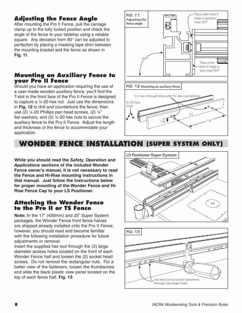
Adjusting the Fence AngleAfter mounting the Pro II Fence, pull the carriage clamp up to the fully locked position and check the angle of the fence to your tabletop using a reliable square. Any deviation from 90° can be adjusted to perfection by placing a masking tape shim between the mounting bracket and the fence as shown in Fig. 11.
Mounting an Auxiliary Fence to your Pro II FenceShould you have an application requiring the use of a user-made wooden auxiliary fence, you’ll find the T-slot in the front face of the Pro II Fence is designed to capture a ¼-20 hex nut. Just use the dimensions in Fig. 12 to drill and counterbore the fence, then use (2) ¼-20 Phillips pan head screws, (2) ¼” flat washers, and (2) ¼-20 hex nuts to secure the auxiliary fence to the Pro II Fence. Adjust the length and thickness of the fence to accommodate your application.
Place shim here if angle is greater than 90º
90ºPlace shim here if angle is less than 90º
WOnDer FenCe InStAllAtIOn (SuPer SYSteM OnlY)
While you should read the Safety, Operation and Applications sections of the included Wonder Fence owner’s manual, it is not necessary to read the Fence and Hi-Rise mounting instructions in that manual. Just follow the instructions below for proper mounting of the Wonder Fence and Hi-Rise Fence Cap to your LS Positioner.
Attaching the Wonder Fence to the Pro II or tS FenceNote: In the 17” (430mm) and 25” Super System packages, the Wonder Fence front fence halves are shipped already installed onto the Pro II Fence; however, you should read and become familiar with the following installation procedure for future adjustments or removal. Insert the supplied hex tool through the (2) large diameter access holes located on the front of each Wonder Fence half and loosen the (2) socket head screws. Do not remove the rectangular nuts. For a better view of the fasteners, loosen the thumbscrew and slide the black plastic view panel located on the top of each fence half, Fig. 13.
FIg. 13
¼-20 hex nuts
14”1¾”
5/16” dia. through holes with 3/4” dia. counterbore
Use hex tool to loosen fasteners through two larger holes
FIg. 12 Mounting an auxiliary fence
FIg. 11 Adjusting the fence angle
LS Positioner Super System
Attach the Fence Cap BracesOpen the Wonder Fence Hi-Rise Fence
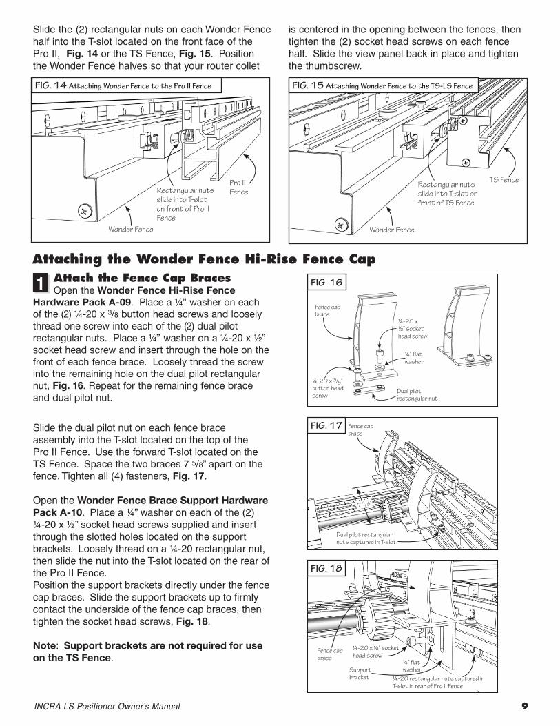
Hardware Pack A-09. Place a ¼” washer on each of the (2) ¼-20 x 3/8 button head screws and loosely thread one screw into each of the (2) dual pilot rectangular nuts. Place a ¼” washer on a ¼-20 x ½” socket head screw and insert through the hole on the front of each fence brace. Loosely thread the screw into the remaining hole on the dual pilot rectangular nut, Fig. 16. Repeat for the remaining fence brace and dual pilot nut.
Slide the dual pilot nut on each fence brace assembly into the T-slot located on the top of the Pro II Fence. Use the forward T-slot located on the TS Fence. Space the two braces 7 5/8” apart on the fence. Tighten all (4) fasteners, Fig. 17.
Open the Wonder Fence Brace Support Hardware Pack A-10. Place a ¼” washer on each of the (2) ¼-20 x ½” socket head screws supplied and insert through the slotted holes located on the support brackets. Loosely thread on a ¼-20 rectangular nut, then slide the nut into the T-slot located on the rear of the Pro II Fence. Position the support brackets directly under the fence cap braces. Slide the support brackets up to firmly contact the underside of the fence cap braces, then tighten the socket head screws, Fig. 18.
Note: Support brackets are not required for use on the TS Fence.
Slide the (2) rectangular nuts on each Wonder Fence half into the T-slot located on the front face of the Pro II, Fig. 14 or the TS Fence, Fig. 15. Position the Wonder Fence halves so that your router collet
is centered in the opening between the fences, then tighten the (2) socket head screws on each fence half. Slide the view panel back in place and tighten the thumbscrew.
INCRALSPositionerOwner’sManual 9
FIg. 14 Attaching Wonder Fence to the Pro II Fence
Pro II FenceRectangular nuts
slide into T-slot on front of Pro II Fence
Wonder Fence
TS FenceRectangular nuts slide into T-slot on front of TS Fence
Wonder Fence
Fence cap brace
¼-20 x ½” socket head screw
¼” flat washer
Dual pilot rectangular nut
¼-20 x 3/8” button head screw
Fence cap brace
Dual pilot rectangular nuts captured in T-slot
7 5/8”
Fence cap brace
¼-20 x ½” socket head screw
¼” flat washer
¼-20 rectangular nuts captured in T-slot in rear of Pro II Fence
Support bracket
1
Attaching the Wonder Fence Hi-rise Fence Cap
FIg. 15 Attaching Wonder Fence to the TS-LS Fence
FIg. 16
FIg. 17
FIg. 18
10 INCRAWoodworkingTools&PrecisionRules
Attach the Cap extenderPlace a ¼” washer on each of the (2) #10-32 x ½”
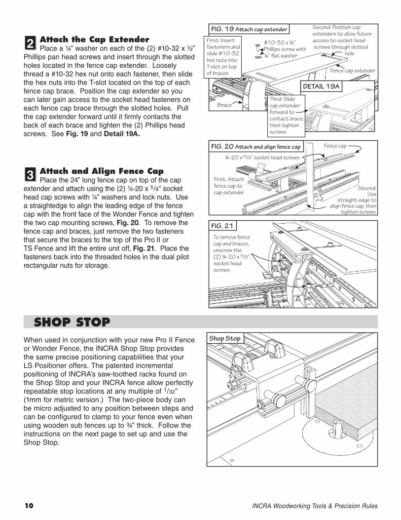
Phillips pan head screws and insert through the slotted holes located in the fence cap extender. Loosely thread a #10-32 hex nut onto each fastener, then slide the hex nuts into the T-slot located on the top of each fence cap brace. Position the cap extender so you can later gain access to the socket head fasteners on each fence cap brace through the slotted holes. Pull the cap extender forward until it firmly contacts the back of each brace and tighten the (2) Phillips head screws. See Fig. 19 and Detail 19A.
Attach and Align Fence CapPlace the 24” long fence cap on top of the cap
extender and attach using the (2) ¼-20 x 5/8” socket head cap screws with ¼” washers and lock nuts. Use a straightedge to align the leading edge of the fence cap with the front face of the Wonder Fence and tighten the two cap mounting screws, Fig. 20. To remove the fence cap and braces, just remove the two fasteners that secure the braces to the top of the Pro II or TS Fence and lift the entire unit off, Fig. 21. Place the fasteners back into the threaded holes in the dual pilot rectangular nuts for storage.
2
3
FIg. 19 Attach cap extender
First: Insert fasteners and slide #10-32 hex nuts into T-slot on top of braces
#10-32 x ½” Phillips screw with ¼” flat washer
Second: Position cap extenders to allow future access to socket head screws through slotted
hole
Fence cap extender
DETAIL 19A
Third: Slide cap extender forward to contact brace, then tighten screws
Brace
FIg. 20 Attach and align fence cap
First: Attach fence cap to cap extender
Second: Use
straight-edge to align fence cap, then
tighten screws
Fence cap
FIg. 21 To remove fence cap and braces, unscrew the (2) ¼-20 x 5/8” socket head screws
SHOP StOPWhen used in conjunction with your new Pro II Fence or Wonder Fence, the INCRA Shop Stop provides the same precise positioning capabilities that your LS Positioner offers. The patented incremental positioning of INCRA’s saw-toothed racks found on the Shop Stop and your INCRA fence allow perfectly repeatable stop locations at any multiple of 1/32” (1mm for metric version.) The two-piece body can be micro adjusted to any position between steps and can be configured to clamp to your fence even when using wooden sub fences up to ¾” thick. Follow the instructions on the next page to set up and use the Shop Stop.
Shop Stop
¼-20 x 5/8” socket head screws
INCRALSPositionerOwner’sManual 11
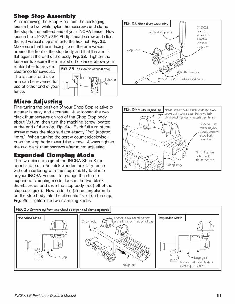
Shop Stop AssemblyAfter removing the Shop Stop from the packaging, loosen the two white nylon thumbscrews and clamp the stop to the outfeed end of your INCRA fence. Now loosen the #10-32 x 3½” Phillips head screw and slide the red vertical stop arm onto the hex nut, Fig. 22. Make sure that the indexing lip on the arm wraps around the front of the stop body and that the arm is flat against the end of the body, Fig. 23. Tighten the fastener to secure the arm a short distance above your router table to provide clearance for sawdust. The fastener and stop arm can be reversed for use at either end of your fence.
FIg. 22 Shop Stop assembly
Shop Stop
#10 flat washer
#10-32 x 3½” Phillips head screw
#10-32 hex nut slides into T-slot on vertical stop arm
Vertical stop arm
FIg. 23 Top view of vertical stop
Indexing lip
Micro AdjustingFine-tuning the position of your Shop Stop relative to a cutter is easy and accurate. Just loosen the two black thumbscrews on top of the Shop Stop body about 1/8 turn, then turn the machine screw located at the end of the stop, Fig. 24. Each full turn of the screw moves the stop surface exactly 1/32” (approx. 1mm.) When turning the screw counterclockwise, push the stop body toward the screw. Always tighten the two black thumbscrews after micro adjusting.
FIg. 24 Micro adjusting First: Loosen both black thumbscrews. Leave both white thumbscrews fully tightened if already installed on fence
Second: Turn micro adjust screw to move stop body position
Third: Tighten both black thumbscrews
Stop body
FIg. 25 Converting from standard to expanded clamping mode
Small gap Large gapReassemble stop body to stop cap as shown
Loosen black thumbscrews and slide stop body off of capStop body
Stop cap
expanded Clamping ModeThe two-piece design of the INCRA Shop Stop permits use of a ¾” thick wooden auxiliary fence without interfering with the stop’s ability to clamp to your INCRA Fence. To change the stop to expanded clamping mode, loosen the two black thumbscrews and slide the stop body (red) off of the stop cap (gold). Now slide the (2) rectangular nuts on the stop body into the alternate T-slot on the cap, Fig. 25. Tighten the two clamping knobs.
Standard Mode Expanded Mode
12 INCRAWoodworkingTools&PrecisionRules
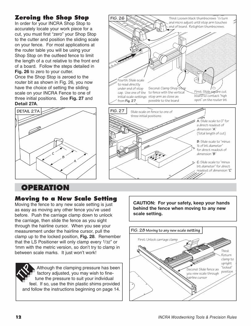
Zeroing the Shop StopIn order for your INCRA Shop Stop to accurately locate your work piece for a cut, you must first “zero” your Shop Stop to the cutter and position the sliding scale on your fence. For most applications at the router table you will be using your Shop Stop on the outfeed fence to limit the length of a cut relative to the front end of a board. Follow the steps detailed in Fig. 26 to zero to your cutter.Once the Shop Stop is zeroed to the router bit as shown in Fig. 26, you now have the choice of setting the sliding scale on your INCRA Fence to one of three initial positions. See Fig. 27 and Detail 27A.
FIg. 26
Fourth: Slide scale to read directly under end of stop cap. Use one of the initial scale settings from Fig. 27
Second: Clamp Shop Stop to fence with the vertical stop arm as close as possible to the board
First: Slide square cut board to contact “high spot” on the router bit
Third: Loosen black thumbscrews 1/8 turn and micro adjust until stop arm touches end of board. Retighten thumbscrews.
FIg. 27 Slide scale on fence to one of three initial positions
A: Slide scale to 0” for a direct readout of dimension “A” (Total length of cut)
B: Slide scale to “minus ½ of bit diameter” for direct readout of dimension “B”
C: Slide scale to “minus bit diameter” for direct readout of dimension “C”
C B A
OPerAtIOnMoving to a new Scale SettingMoving the fence to any new scale setting is just as easy as moving any other fence you’ve used before. Push the carriage clamp down to unlock the carriage, then slide the fence as you sight through the hairline cursor. When you see your measurement under the hairline cursor, pull the clamp up to the locked position, Fig. 28. Remember that the LS Positioner will only clamp every 1/32” or 1mm with the metric version, so don’t try to clamp in between scale marks. It just won’t work!
Although the clamping pressure has been factory adjusted, you may wish to fine-
tune the pressure to suit your individual feel. If so, use the thin plastic shims provided
and follow the instructions beginning on page 14.
FIg. 28 Moving to any new scale setting
First: Unlock carriage clamp
Second: Slide fence as you view scale through hairline cursor
Third: Return clamp to upright “locked”position
CAUTION: For your safety, keep your hands behind the fence when moving to any new scale setting.
DETAIL 27A
CB
A
INCRALSPositionerOwner’sManual 13
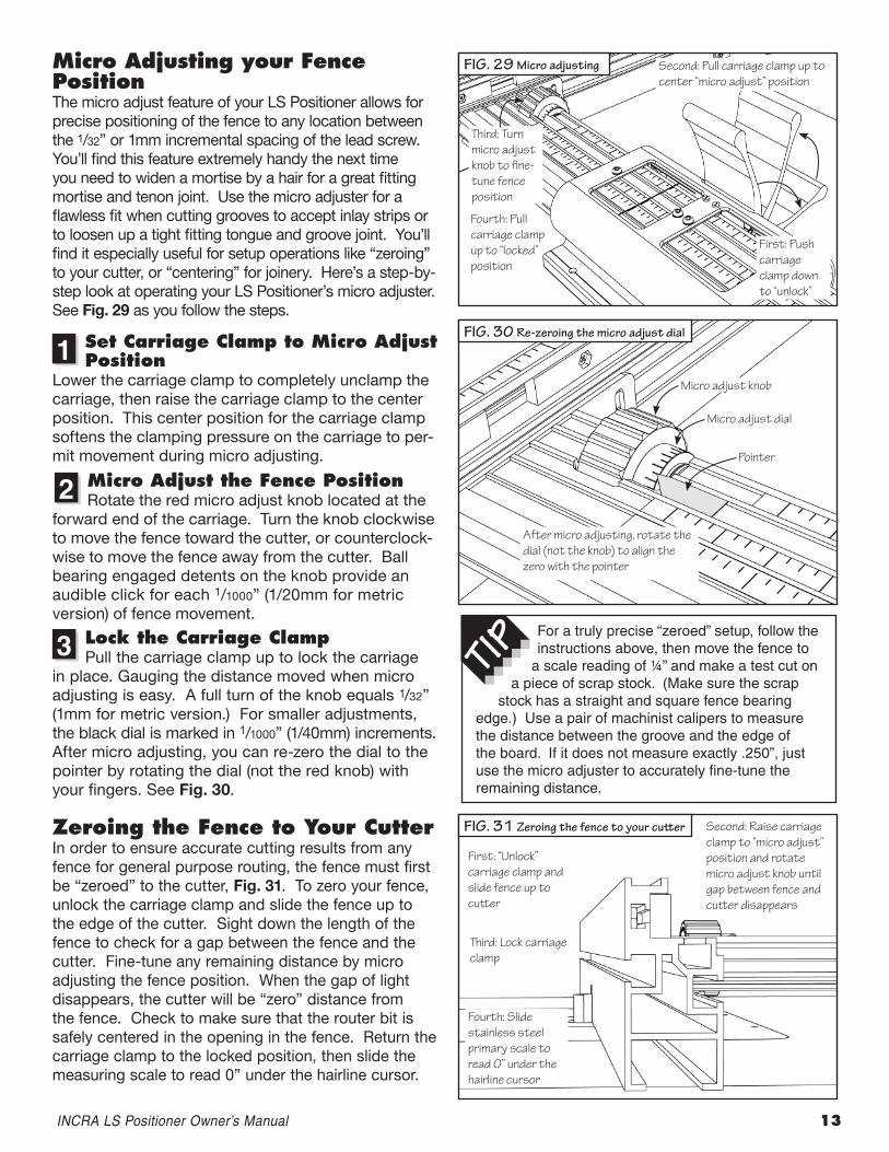
Micro Adjusting your Fence PositionThe micro adjust feature of your LS Positioner allows for precise positioning of the fence to any location between the 1/32” or 1mm incremental spacing of the lead screw. You’ll find this feature extremely handy the next time you need to widen a mortise by a hair for a great fitting mortise and tenon joint. Use the micro adjuster for a flawless fit when cutting grooves to accept inlay strips or to loosen up a tight fitting tongue and groove joint. You’ll find it especially useful for setup operations like “zeroing” to your cutter, or “centering” for joinery. Here’s a step-by-step look at operating your LS Positioner’s micro adjuster. See Fig. 29 as you follow the steps.
Set Carriage Clamp to Micro Adjust Position
Lower the carriage clamp to completely unclamp the carriage, then raise the carriage clamp to the center position. This center position for the carriage clamp softens the clamping pressure on the carriage to per-mit movement during micro adjusting.
Micro Adjust the Fence Position Rotate the red micro adjust knob located at the
forward end of the carriage. Turn the knob clockwise to move the fence toward the cutter, or counterclock-wise to move the fence away from the cutter. Ball bearing engaged detents on the knob provide an audible click for each 1/1000” (1/20mm for metric version) of fence movement.
lock the Carriage ClampPull the carriage clamp up to lock the carriage
in place. Gauging the distance moved when micro adjusting is easy. A full turn of the knob equals 1/32” (1mm for metric version.) For smaller adjustments, the black dial is marked in 1/1000” (1/40mm) increments. After micro adjusting, you can re-zero the dial to the pointer by rotating the dial (not the red knob) with your fingers. See Fig. 30.
Zeroing the Fence to Your Cutter In order to ensure accurate cutting results from any fence for general purpose routing, the fence must first be “zeroed” to the cutter, Fig. 31. To zero your fence, unlock the carriage clamp and slide the fence up to the edge of the cutter. Sight down the length of the fence to check for a gap between the fence and the cutter. Fine-tune any remaining distance by micro adjusting the fence position. When the gap of light disappears, the cutter will be “zero” distance from the fence. Check to make sure that the router bit is safely centered in the opening in the fence. Return the carriage clamp to the locked position, then slide the measuring scale to read 0” under the hairline cursor.
1
2
3For a truly precise “zeroed” setup, follow the instructions above, then move the fence to
a scale reading of ¼” and make a test cut on a piece of scrap stock. (Make sure the scrap
stock has a straight and square fence bearing edge.) Use a pair of machinist calipers to measure the distance between the groove and the edge of the board. If it does not measure exactly .250”, just use the micro adjuster to accurately fine-tune the remaining distance.
FIg. 29 Micro adjusting
Fourth: Pull carriage clamp up to “locked” position
Third: Turn micro adjust knob to fine-tune fence position
First: Push carriage clamp down to “unlock”
Second: Pull carriage clamp up to center “micro adjust” position
FIg. 30 Re-zeroing the micro adjust dial
After micro adjusting, rotate the dial (not the knob) to align the zero with the pointer
Micro adjust knob
Micro adjust dial
Pointer
FIg. 31 Zeroing the fence to your cutter
First: “Unlock” carriage clamp and slide fence up to cutter
Second: Raise carriage clamp to “micro adjust” position and rotate micro adjust knob until gap between fence and cutter disappears
Third: Lock carriage clamp
Fourth: Slide stainless steel primary scale to read 0” under the hairline cursor
14 INCRAWoodworkingTools&PrecisionRules
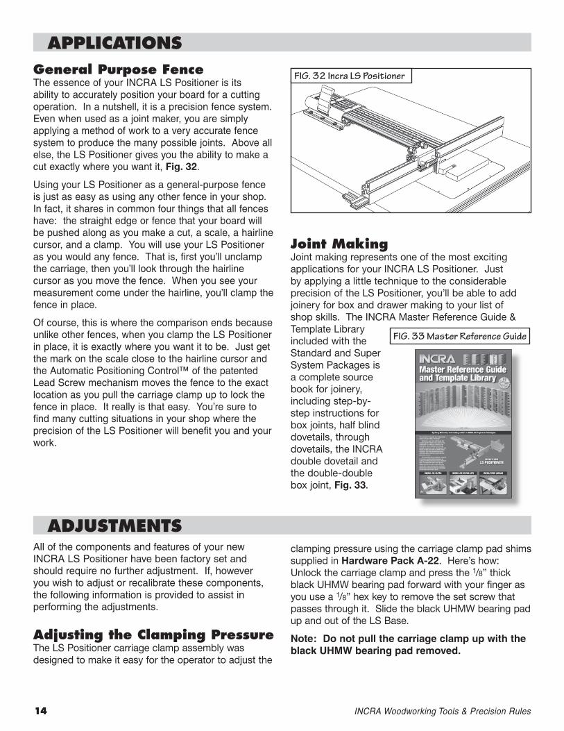
General Purpose FenceThe essence of your INCRA LS Positioner is its ability to accurately position your board for a cutting operation. In a nutshell, it is a precision fence system. Even when used as a joint maker, you are simply applying a method of work to a very accurate fence system to produce the many possible joints. Above all else, the LS Positioner gives you the ability to make a cut exactly where you want it, Fig. 32.
Using your LS Positioner as a general-purpose fence is just as easy as using any other fence in your shop. In fact, it shares in common four things that all fences have: the straight edge or fence that your board will be pushed along as you make a cut, a scale, a hairline cursor, and a clamp. You will use your LS Positioner as you would any fence. That is, first you’ll unclamp the carriage, then you’ll look through the hairline cursor as you move the fence. When you see your measurement come under the hairline, you’ll clamp the fence in place.
Of course, this is where the comparison ends because unlike other fences, when you clamp the LS Positioner in place, it is exactly where you want it to be. Just get the mark on the scale close to the hairline cursor and the Automatic Positioning Control™ of the patented Lead Screw mechanism moves the fence to the exact location as you pull the carriage clamp up to lock the fence in place. It really is that easy. You’re sure to find many cutting situations in your shop where the precision of the LS Positioner will benefit you and your work.
Joint MakingJoint making represents one of the most exciting applications for your INCRA LS Positioner. Just by applying a little technique to the considerable precision of the LS Positioner, you’ll be able to add joinery for box and drawer making to your list of shop skills. The INCRA Master Reference Guide & Template Library included with the Standard and Super System Packages is a complete source book for joinery, including step-by-step instructions for box joints, half blind dovetails, through dovetails, the INCRA double dovetail and the double-double box joint, Fig. 33.
APPlICAtIOnS
ADJuStMentS
FIg. 32 Incra LS Positioner
FIg. 33 Master Reference guide
All of the components and features of your new INCRA LS Positioner have been factory set and should require no further adjustment. If, however you wish to adjust or recalibrate these components, the following information is provided to assist in performing the adjustments.
Adjusting the Clamping PressureThe LS Positioner carriage clamp assembly was designed to make it easy for the operator to adjust the
clamping pressure using the carriage clamp pad shims supplied in Hardware Pack A-22. Here’s how: Unlock the carriage clamp and press the 1/8” thick black UHMW bearing pad forward with your finger as you use a 1/8” hex key to remove the set screw that passes through it. Slide the black UHMW bearing pad up and out of the LS Base.
Note: Do not pull the carriage clamp up with the black UHMW bearing pad removed.
INCRALSPositionerOwner’sManual 15
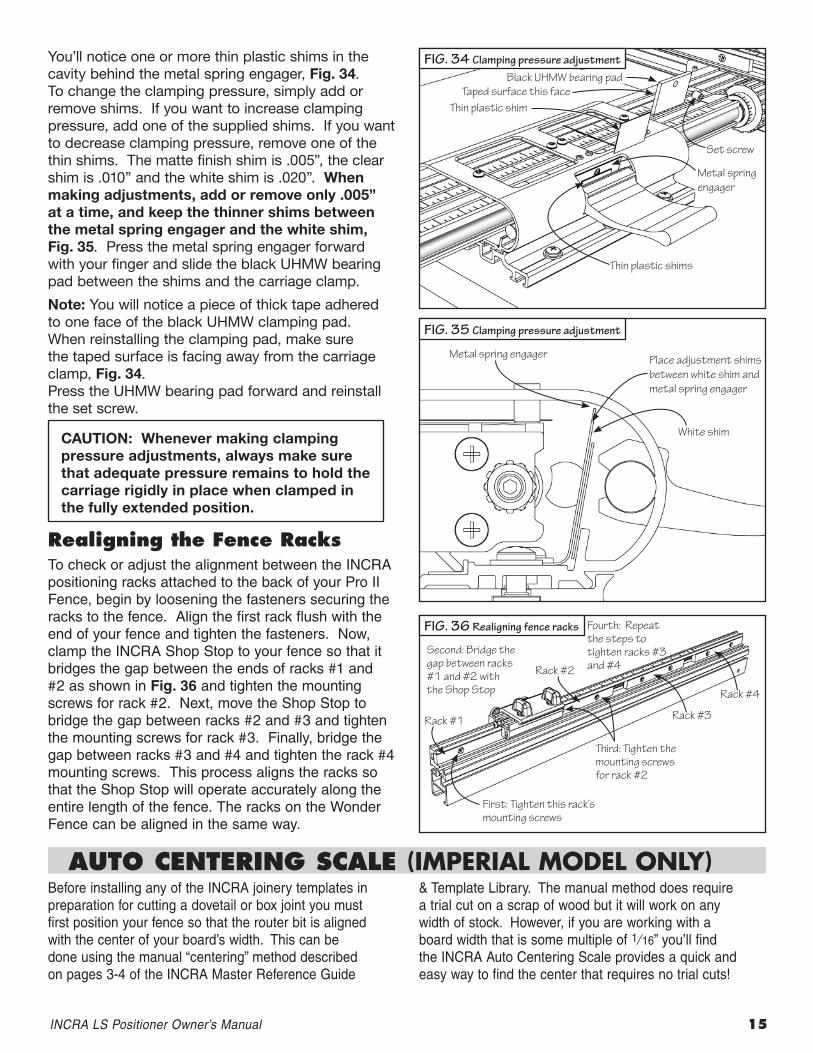
You’ll notice one or more thin plastic shims in the cavity behind the metal spring engager, Fig. 34. To change the clamping pressure, simply add or remove shims. If you want to increase clamping pressure, add one of the supplied shims. If you want to decrease clamping pressure, remove one of the thin shims. The matte finish shim is .005”, the clear shim is .010” and the white shim is .020”. When making adjustments, add or remove only .005” at a time, and keep the thinner shims between the metal spring engager and the white shim, Fig. 35. Press the metal spring engager forward with your finger and slide the black UHMW bearing pad between the shims and the carriage clamp.
Note: You will notice a piece of thick tape adhered to one face of the black UHMW clamping pad. When reinstalling the clamping pad, make sure the taped surface is facing away from the carriage clamp, Fig. 34. Press the UHMW bearing pad forward and reinstall the set screw.
realigning the Fence racksTo check or adjust the alignment between the INCRA positioning racks attached to the back of your Pro II Fence, begin by loosening the fasteners securing the racks to the fence. Align the first rack flush with the end of your fence and tighten the fasteners. Now, clamp the INCRA Shop Stop to your fence so that it bridges the gap between the ends of racks #1 and #2 as shown in Fig. 36 and tighten the mounting screws for rack #2. Next, move the Shop Stop to bridge the gap between racks #2 and #3 and tighten the mounting screws for rack #3. Finally, bridge the gap between racks #3 and #4 and tighten the rack #4 mounting screws. This process aligns the racks so that the Shop Stop will operate accurately along the entire length of the fence. The racks on the Wonder Fence can be aligned in the same way.
CAUTION: Whenever making clamping pressure adjustments, always make sure that adequate pressure remains to hold the carriage rigidly in place when clamped in the fully extended position.
FIg. 34 Clamping pressure adjustmentBlack UHMW bearing pad
Set screw
Thin plastic shim
Metal spring engager
Thin plastic shims
FIg. 35 Clamping pressure adjustment
Metal spring engager
White shim
Place adjustment shims between white shim and metal spring engager
FIg. 36 Realigning fence racks
Second: Bridge the gap between racks #1 and #2 with the Shop Stop Rack #4
Rack #3
Rack #2
Rack #1
Third: Tighten the mounting screws for rack #2
Fourth: Repeat the steps to tighten racks #3 and #4
First: Tighten this rack’s mounting screws
Taped surface this face
AutO CenterInG SCAle (ImperIal model only)Before installing any of the INCRA joinery templates in preparation for cutting a dovetail or box joint you must first position your fence so that the router bit is aligned with the center of your board’s width. This can be done using the manual “centering” method described on pages 3-4 of the INCRA Master Reference Guide
& Template Library. The manual method does require a trial cut on a scrap of wood but it will work on any width of stock. However, if you are working with a board width that is some multiple of 1⁄16” you’ll find the INCRA Auto Centering Scale provides a quick and easy way to find the center that requires no trial cuts!
Made in America by:Taylor Design Group, Inc. P.O. Box 810262 Dallas, Texas 75381 Tel: (972) 242-9975 Fax: (972) 243-4277 Web Site: www.incra.com
Printed in the U.S.A. © 2010 Taylor Design Group, Inc. INCRA is a registered trademark of Taylor Design Group, Inc.
WArrAntYTaylor Design Group, Inc. warrants this product for one year from date of purchase. We will repair any defects due to faulty material or workmanship, or at our option, replace the product free of charge. Please return the failing component only, postage prepaid, along with a description of the problem to the address below. This warranty does not apply to parts which have been subjected to improper use, alteration, or abuse. 02/05
Positioning the Auto Centering Scale (Imperial Model Only)
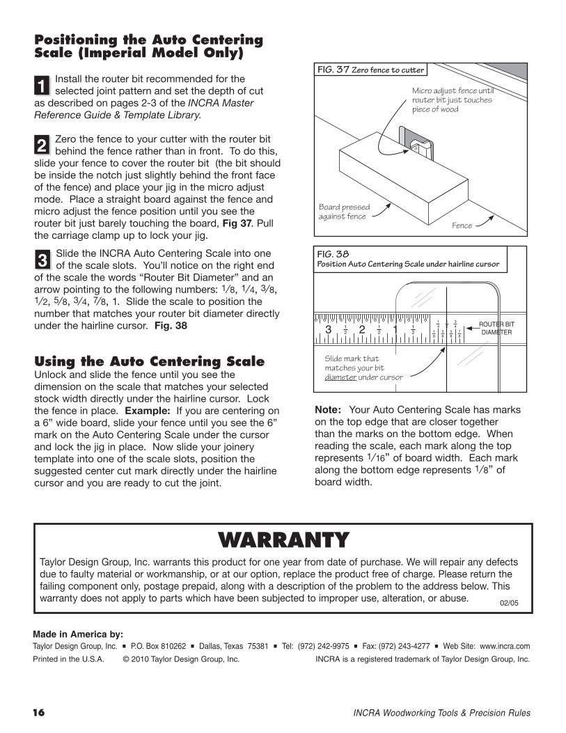
Install the router bit recommended for the selected joint pattern and set the depth of cut
as described on pages 2-3 of the INCRA Master Reference Guide & Template Library.
Zero the fence to your cutter with the router bit behind the fence rather than in front. To do this,
slide your fence to cover the router bit (the bit should be inside the notch just slightly behind the front face of the fence) and place your jig in the micro adjust mode. Place a straight board against the fence and micro adjust the fence position until you see the router bit just barely touching the board, Fig 37. Pull the carriage clamp up to lock your jig.
Slide the INCRA Auto Centering Scale into one of the scale slots. You’ll notice on the right end
of the scale the words “Router Bit Diameter” and an arrow pointing to the following numbers: 1 ⁄8, 1 ⁄4, 3 ⁄8, 1 ⁄2, 5 ⁄8, 3 ⁄4, 7⁄8, 1. Slide the scale to position the number that matches your router bit diameter directly under the hairline cursor. Fig. 38
using the Auto Centering ScaleUnlock and slide the fence until you see the dimension on the scale that matches your selected stock width directly under the hairline cursor. Lock the fence in place. Example: If you are centering on a 6” wide board, slide your fence until you see the 6” mark on the Auto Centering Scale under the cursor and lock the jig in place. Now slide your joinery template into one of the scale slots, position the suggested center cut mark directly under the hairline cursor and you are ready to cut the joint.
FIg. 37 Zero fence to cutter
FIg. 38 Position Auto Centering Scale under hairline cursor
Board pressed against fence
Micro adjust fence until router bit just touches piece of wood
Fence
Slide mark that matches your bit diameter under cursor
1
2
3
Note: Your Auto Centering Scale has marks on the top edge that are closer together than the marks on the bottom edge. When reading the scale, each mark along the top represents 1 ⁄16” of board width. Each mark along the bottom edge represents 1 ⁄8” of board width.
16 INCRAWoodworkingTools&PrecisionRules