Embed Size (px)
Citation preview
Increasing Fiber Capacity with CWDM
A Tutorial on CWDM Network Design
Presented by:
Greg Scott
MSO/Telecom Sales
Increasing Fiber Capacity with CWDM
Introduction
WDM Technology Overview
CWDM and Fiber Cabling
Multiplexing Equipment
Application Examples
Wavelength Conversion
Charter Examples
3© 2012 Omnitron Systems
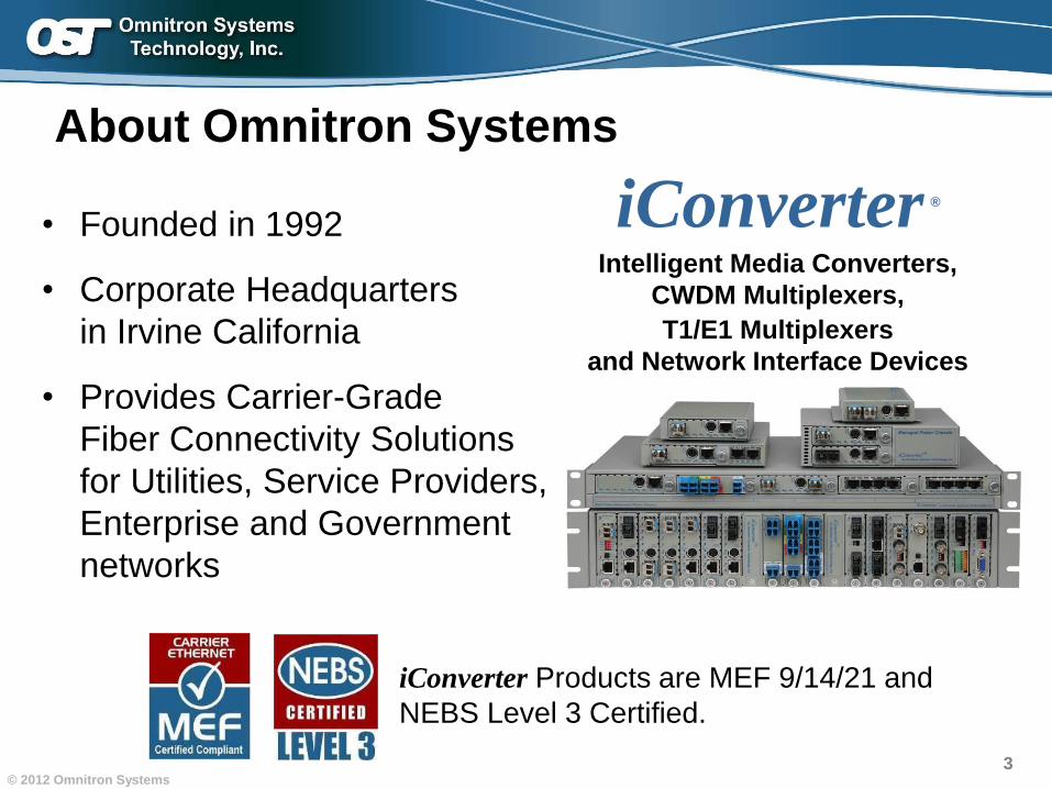
About Omnitron Systems
• Founded in 1992
• Corporate Headquarters
in Irvine California
• Provides Carrier-Grade
Fiber Connectivity Solutions
for Utilities, Service Providers,
Enterprise and Government
networks
iConverter Products are MEF 9/14/21 and
NEBS Level 3 Certified.
iConverter ®
Intelligent Media Converters,
CWDM Multiplexers,
T1/E1 Multiplexers
and Network Interface Devices
4© 2012 Omnitron Systems
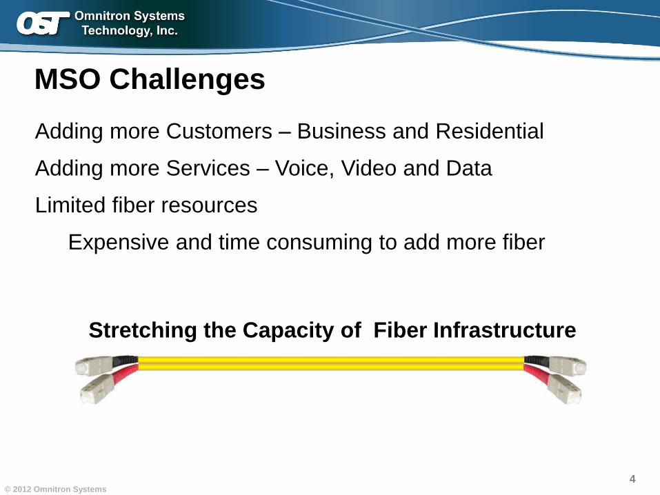
MSO Challenges
Adding more Customers – Business and Residential
Adding more Services – Voice, Video and Data
Limited fiber resources
Expensive and time consuming to add more fiber
Stretching the Capacity of Fiber Infrastructure
5© 2012 Omnitron Systems
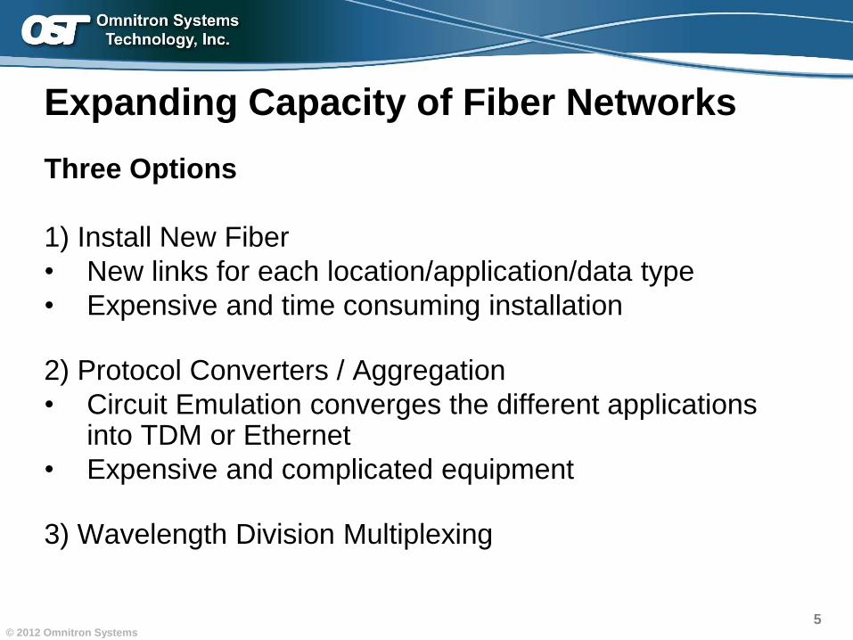
Expanding Capacity of Fiber Networks
Three Options
1) Install New Fiber
• New links for each location/application/data type
• Expensive and time consuming installation
2) Protocol Converters / Aggregation
• Circuit Emulation converges the different applications into TDM or Ethernet
• Expensive and complicated equipment
3) Wavelength Division Multiplexing

Increasing Fiber Capacity with CWDMIncreasing Fiber Capacity with CWDM
Introduction
WDM Technology Overview
CWDM and Fiber Cabling
Multiplexing Equipment
Application Examples
Wavelength Conversion
Charter Examples
7© 2012 Omnitron Systems
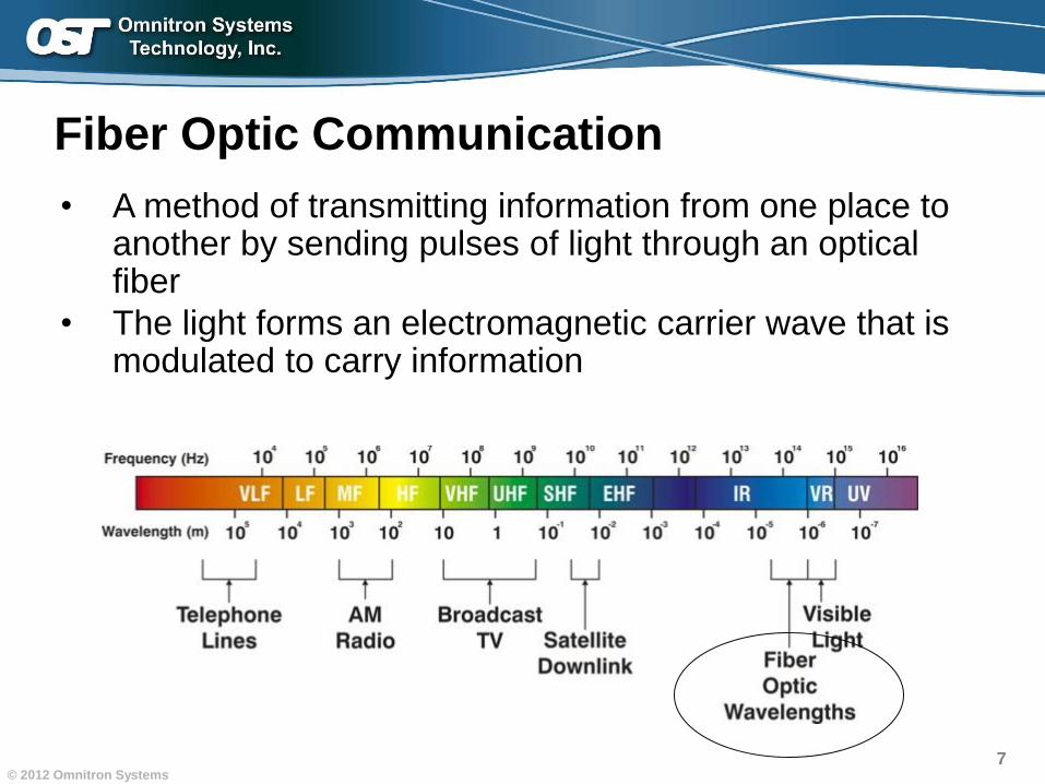
Fiber Optic Communication
• A method of transmitting information from one place to another by sending pulses of light through an optical fiber
• The light forms an electromagnetic carrier wave that is modulated to carry information
8© 2012 Omnitron Systems
WDM Overview
Wavelength Division Multiplexing
• Overlaying multiple wavelengths/colors on one fiber link
– Each wavelength is a secure and an independent data channel
– Each channel is protocol and speed transparent (up to 10 Gig)
– Increases the capacity of the fiber infrastructure
• Inexpensive when compared to the alternative solutions
• Implementation has little to no impact to existing network
– Legacy 1310nm or 1550nm network unaware of xWDM
wavelengths on same fiber
9© 2012 Omnitron Systems
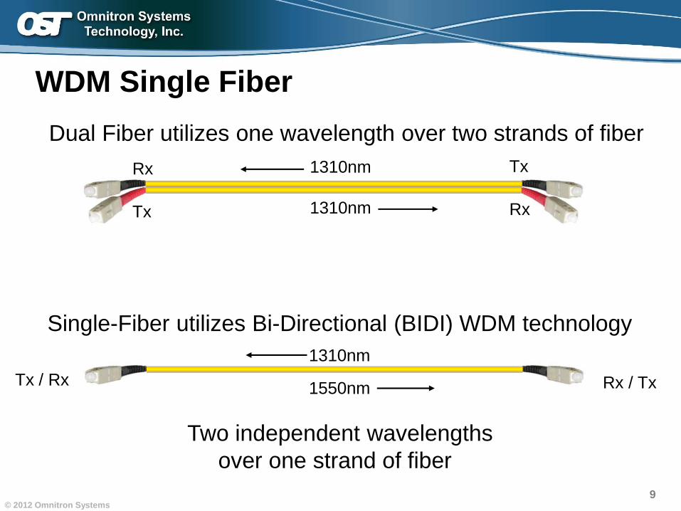
WDM Single Fiber
Single-Fiber utilizes Bi-Directional (BIDI) WDM technology
1310nm
1310nm
Dual Fiber utilizes one wavelength over two strands of fiber
Two independent wavelengths
over one strand of fiber
Rx
Tx
Tx
Rx
Tx / Rx Rx / Tx
1310nm
1550nm
10© 2012 Omnitron Systems
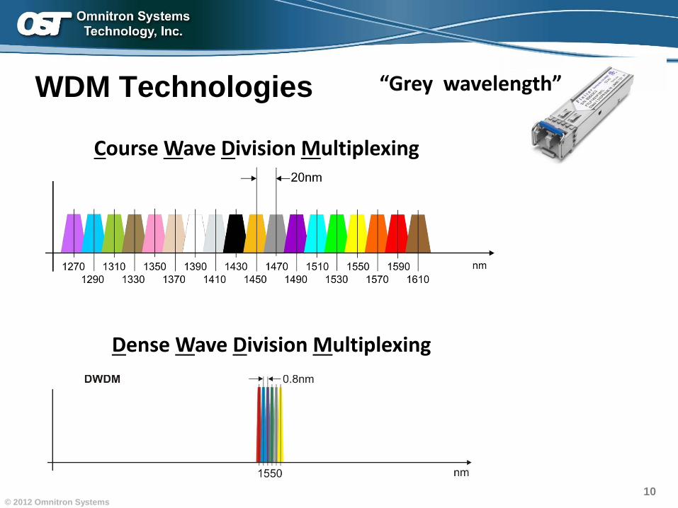
WDM Technologies
Dense Wave Division Multiplexing
Course Wave Division Multiplexing
“Grey wavelength”
11© 2012 Omnitron Systems
DWDM and CWDM
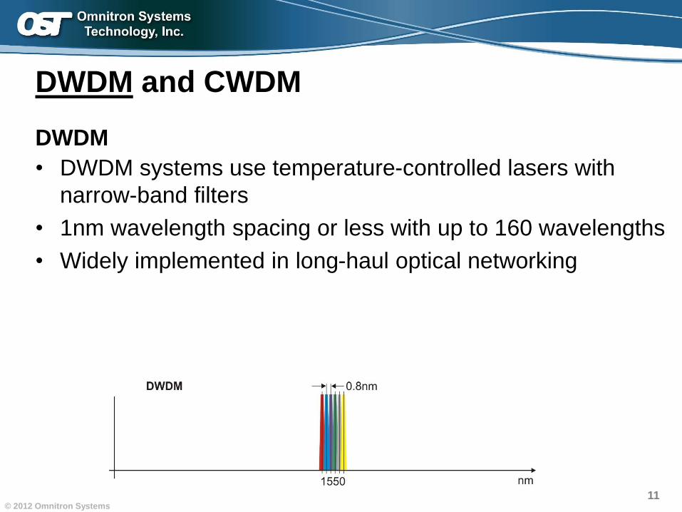
DWDM
• DWDM systems use temperature-controlled lasers with
narrow-band filters
• 1nm wavelength spacing or less with up to 160 wavelengths
• Widely implemented in long-haul optical networking
12© 2012 Omnitron Systems
DWDM and CWDM
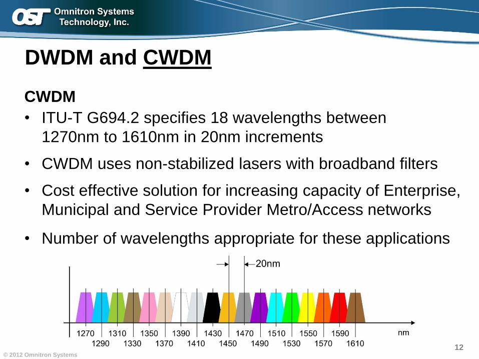
CWDM
• ITU-T G694.2 specifies 18 wavelengths between
1270nm to 1610nm in 20nm increments
• CWDM uses non-stabilized lasers with broadband filters
• Cost effective solution for increasing capacity of Enterprise,
Municipal and Service Provider Metro/Access networks
• Number of wavelengths appropriate for these applications
13© 2012 Omnitron Systems
DWDM and CWDM: L-TWC vs L-Charter
Some Observations
• L-Charter more likely to deploy DWDM and L-TWC more
likely to deploy CWDM (esp business applications)
• But both use CWDM and DWDM mix today
• Main reason CWDM persists is cost.
• As DWDM optics drop in price we’ll see less CWDM.
14© 2012 Omnitron Systems
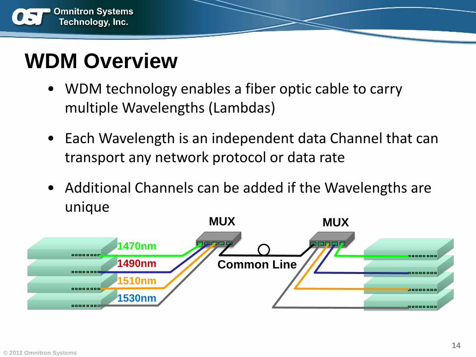
• WDM technology enables a fiber optic cable to carry multiple Wavelengths (Lambdas)
• Each Wavelength is an independent data Channel that can transport any network protocol or data rate
• Additional Channels can be added if the Wavelengths are unique
1470nm
1490nm
1510nm
1530nm
Common Line
MUX MUX
WDM Overview
15© 2012 Omnitron Systems
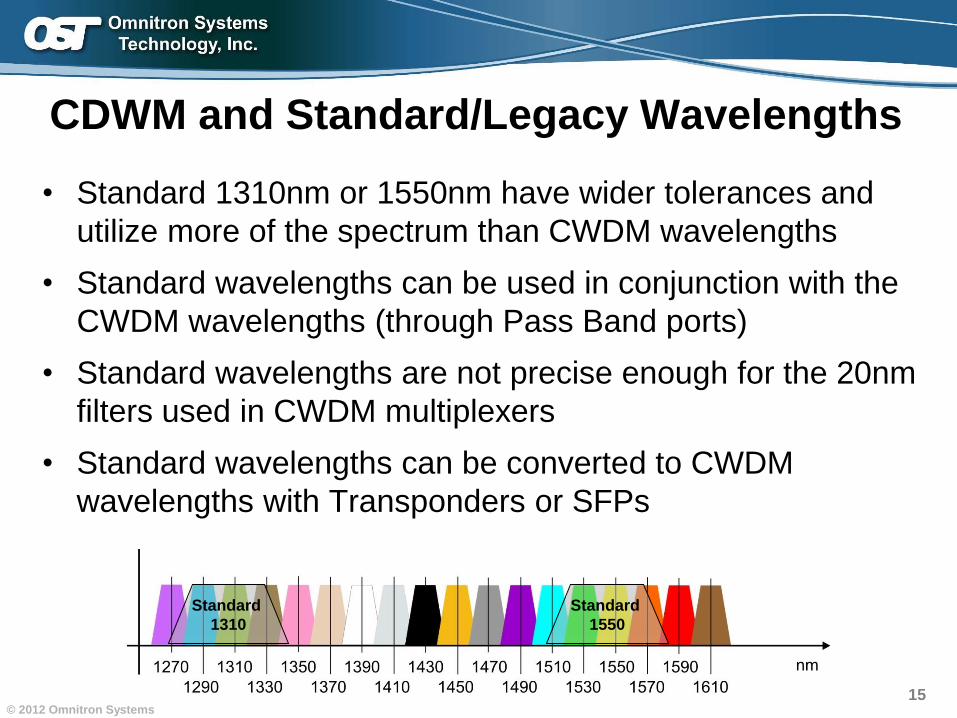
CDWM and Standard/Legacy Wavelengths
• Standard 1310nm or 1550nm have wider tolerances and
utilize more of the spectrum than CWDM wavelengths
• Standard wavelengths can be used in conjunction with the
CWDM wavelengths (through Pass Band ports)
• Standard wavelengths are not precise enough for the 20nm
filters used in CWDM multiplexers
• Standard wavelengths can be converted to CWDM
wavelengths with Transponders or SFPs
Standard
1310
Standard
1550
16
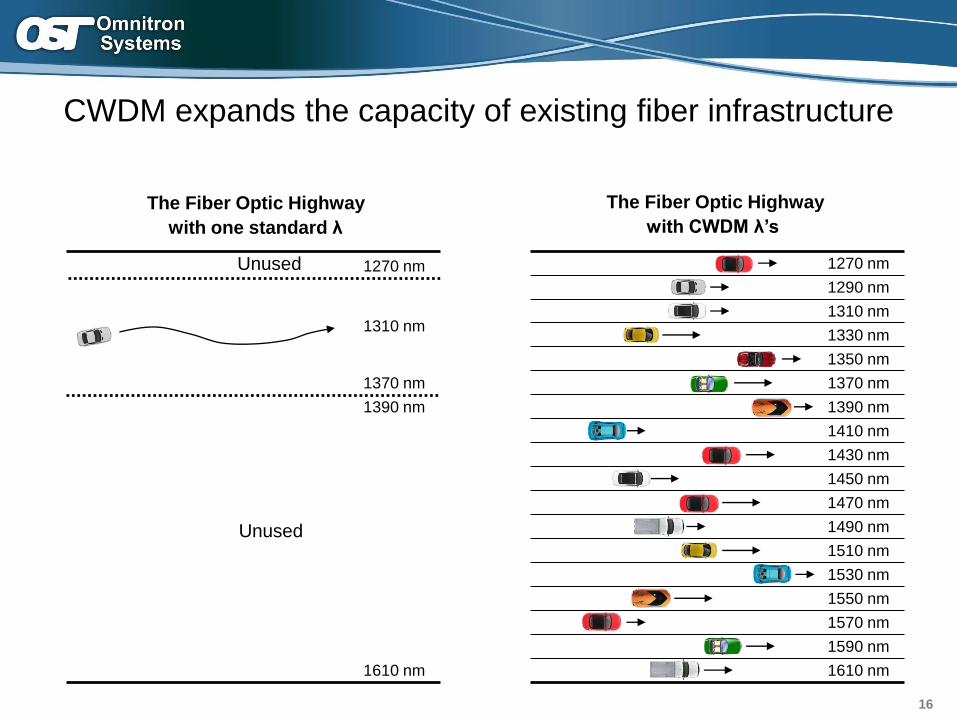
CWDM expands the capacity of existing fiber infrastructure
Unused
The Fiber Optic Highway
with one standard λ
1610 nm
1310 nm
1390 nm
1270 nm
1370 nm
Unused
1470 nm
1490 nm
1510 nm
1530 nm
1610 nm
1550 nm
1570 nm
1590 nm
1310 nm
1330 nm
1350 nm
1370 nm
1450 nm
1390 nm
1410 nm
1430 nm
The Fiber Optic Highway
with CWDM λ’s
1290 nm
1270 nm
17© 2012 Omnitron Systems
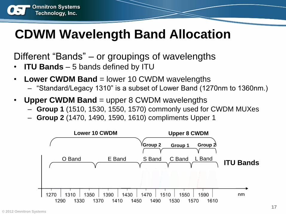
CDWM Wavelength Band Allocation
Different “Bands” – or groupings of wavelengths• ITU Bands – 5 bands defined by ITU
• Lower CWDM Band = lower 10 CWDM wavelengths– “Standard/Legacy 1310” is a subset of Lower Band (1270nm to 1360nm.)
• Upper CWDM Band = upper 8 CWDM wavelengths– Group 1 (1510, 1530, 1550, 1570) commonly used for CWDM MUXes
– Group 2 (1470, 1490, 1590, 1610) compliments Upper 1
Lower 10 CWDM Upper 8 CWDM
O Band C BandE Band S Band L BandITU Bands
Group 1 Group 2Group 2

Increasing Fiber Capacity with CWDMIncreasing Fiber Capacity with CWDM
Introduction
WDM Technology Overview
CWDM and Fiber Cabling
Multiplexing Equipment
Application Examples
Wavelength Conversion
Charter Examples
19© 2012 Omnitron Systems
Definition of Terms
Attenuation / Optical loss
• The rate at which an optical signal decreases in intensity
Dispersion
• The spreading of light pulses as they travel through fiber optic cable.
• Dispersion results in distortion of the signal, which limits the bandwidth and distance of the fiber
Optical Power Budget
• The difference between the minimum transmit power and the minimum receiver sensitivity of the optical devices connected across a fiber optic link.
20© 2012 Omnitron Systems
Fiber Types for CWDM Applications
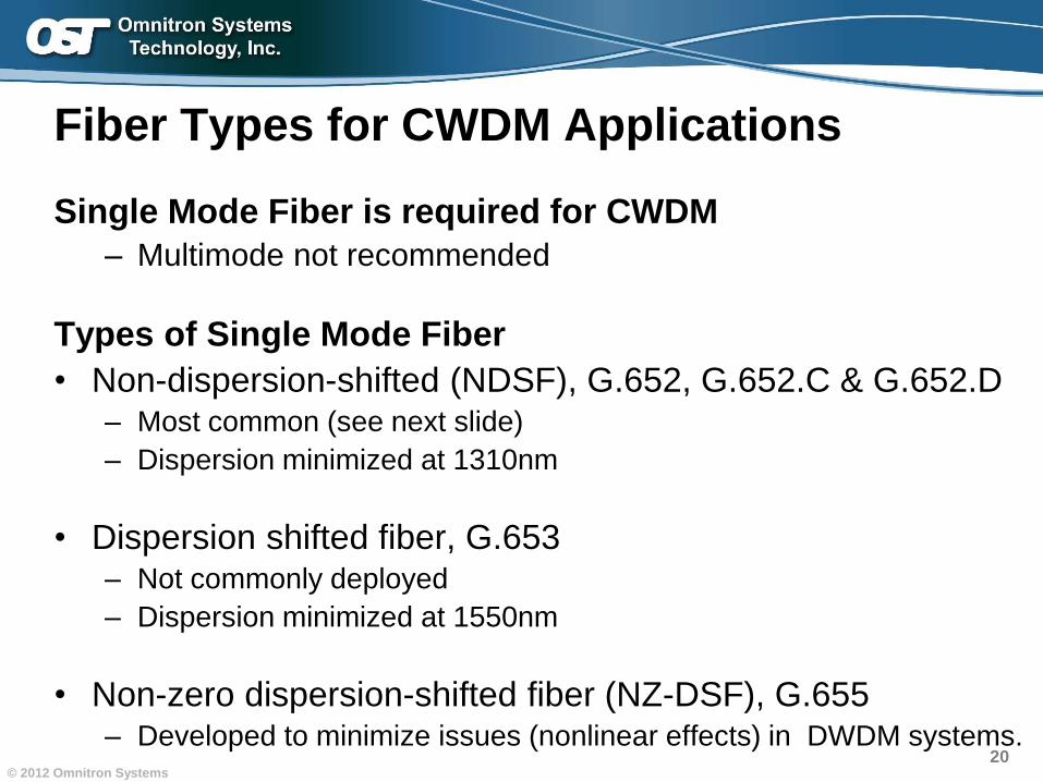
Single Mode Fiber is required for CWDM
– Multimode not recommended
Types of Single Mode Fiber
• Non-dispersion-shifted (NDSF), G.652, G.652.C & G.652.D– Most common (see next slide)
– Dispersion minimized at 1310nm
• Dispersion shifted fiber, G.653– Not commonly deployed
– Dispersion minimized at 1550nm
• Non-zero dispersion-shifted fiber (NZ-DSF), G.655 – Developed to minimize issues (nonlinear effects) in DWDM systems.
21© 2012 Omnitron Systems
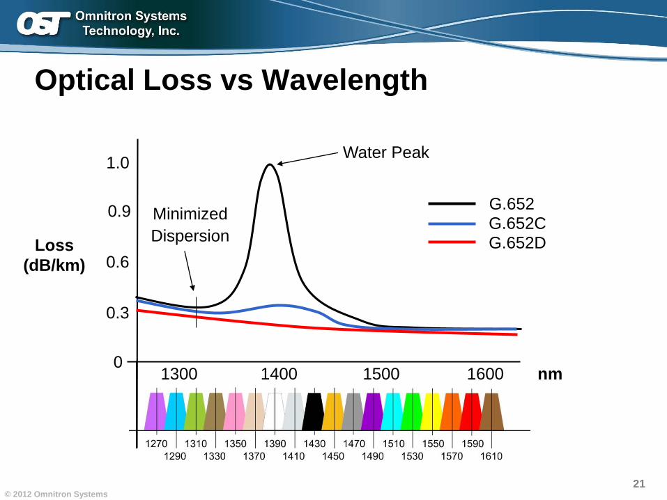
Optical Loss vs Wavelength
Loss
(dB/km)
nm1300 1400 1500 1600
1.0
0.9
0.6
0.3
0
G.652G.652C
Water Peak
G.652D
Minimized
Dispersion
22© 2012 Omnitron Systems
Fiber Types for CWDM Applications
1) Know the type of fiber installed in your network• Contact the manufacturer
• Test your fiber links
2) Plan accordingly• Determine the areas of the spectrum that have the highest
attenuation in the fiber link
• Use the optimum attenuation areas of the CWDM spectrum
in your design
23© 2012 Omnitron Systems
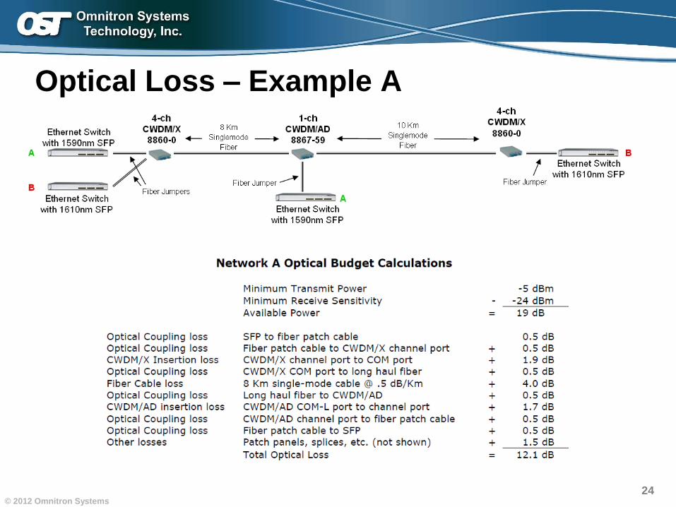
Optical Loss
There are many factors that can result in optical
signal loss in a CWDM network…– Fiber loss (depends on length and type of the fiber used)
– Passive device insertion loss (CWDM MUX and CWDM
OADM)
– Connectors (couplings)
– Patch panels and splices
When calculating optical loss …– The total loss plus safety factor (typically 3dB) must not exceed
the optical power budget.
– The optical power budget is calculated by subtracting the
minimum receive sensitivity from the minimum transmit power.
24© 2012 Omnitron Systems
Optical Loss – Example A
25© 2012 Omnitron Systems
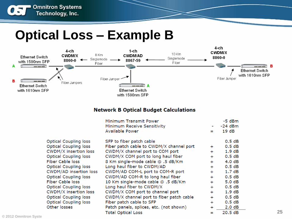
Optical Loss – Example B
Increasing Fiber Capacity with CWDMIncreasing Fiber Capacity with CWDM
Introduction
WDM Technology Overview
CWDM and Fiber Cabling
Multiplexing Equipment
Application Examples
Wavelength Conversion
Charter Examples
27© 2012 Omnitron Systems
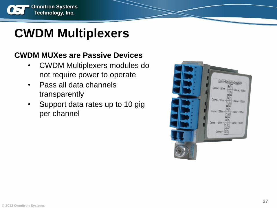
CWDM Multiplexers
CWDM MUXes are Passive Devices
• CWDM Multiplexers modules do
not require power to operate
• Pass all data channels
transparently
• Support data rates up to 10 gig
per channel
28© 2012 Omnitron Systems
Channel 2
Channel 3
Channel 4
Channel 1
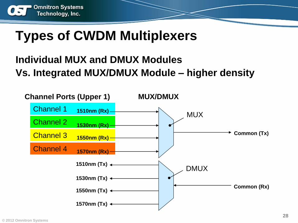
Types of CWDM Multiplexers
Channel Ports (Upper 1)
1510nm (Tx)
1530nm (Tx)
1550nm (Tx)
1570nm (Tx)
Common (Rx)
Common (Tx)
1510nm (Rx)
1530nm (Rx)
1550nm (Rx)
1570nm (Rx)
Individual MUX and DMUX Modules
Vs. Integrated MUX/DMUX Module – higher density
MUX
DMUX
MUX/DMUX
29© 2012 Omnitron Systems
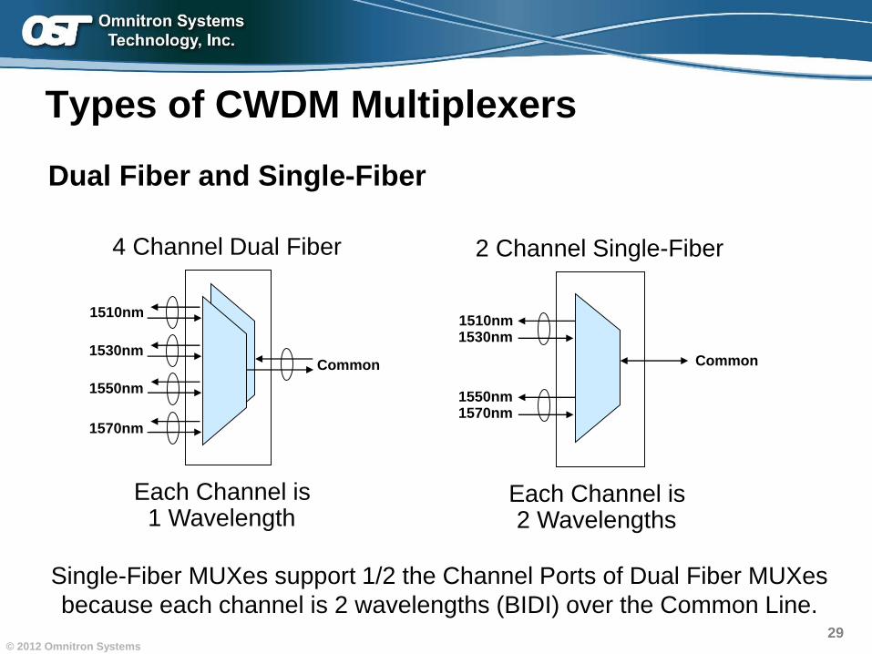
Types of CWDM Multiplexers
Dual Fiber and Single-Fiber
1510nm
1530nm
1550nm
1570nm
Common
4 Channel Dual Fiber
1510nm1530nm
1550nm1570nm
Common
2 Channel Single-Fiber
Single-Fiber MUXes support 1/2 the Channel Ports of Dual Fiber MUXes
because each channel is 2 wavelengths (BIDI) over the Common Line.
Each Channel is 1 Wavelength
Each Channel is 2 Wavelengths
30© 2012 Omnitron Systems
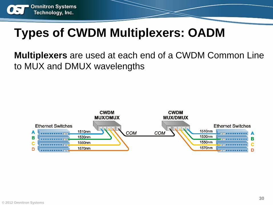
Types of CWDM Multiplexers: OADM
Multiplexers are used at each end of a CWDM Common Line
to MUX and DMUX wavelengths
31© 2012 Omnitron Systems
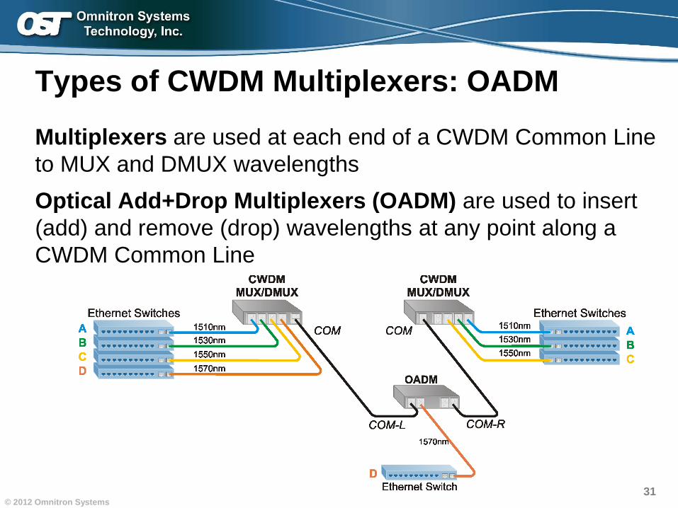
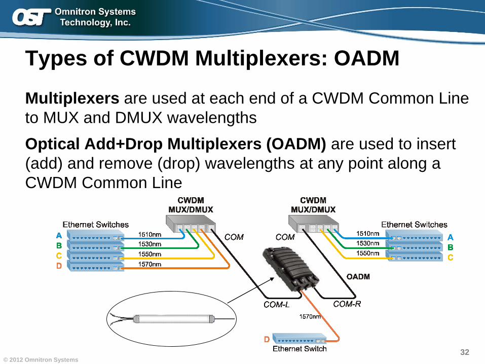
Types of CWDM Multiplexers: OADM
Multiplexers are used at each end of a CWDM Common Line
to MUX and DMUX wavelengths
Optical Add+Drop Multiplexers (OADM) are used to insert
(add) and remove (drop) wavelengths at any point along a
CWDM Common Line
32© 2012 Omnitron Systems
Types of CWDM Multiplexers: OADM
Multiplexers are used at each end of a CWDM Common Line
to MUX and DMUX wavelengths
Optical Add+Drop Multiplexers (OADM) are used to insert
(add) and remove (drop) wavelengths at any point along a
CWDM Common Line
33© 2012 Omnitron Systems
Definitions
Channel Port
• A port for a specific CWDM wavelength
Common Port
• A port for the CWDM Common Line that transmits/receives
all multiplexed wavelengths
1310 Pass Band Port
• A port which connects directly to communications equipment
and enables standard/legacy 1310nm wavelength to pass
transparently
• Examples:– Modulated analog signal / broadcast TV
– 10GBASE-LR Ethernet
– OC3/12/48 SONET
34© 2012 Omnitron Systems
Port Definitions
Expansion Port
• Cascades multiple MUX/DEMUX modules, e.g.: cascading two 8-Channel MUX modules yields 16 channels
• Can also function as a 1550 Pass Band port
• Also called an Upgrade Port or Express Port
35© 2012 Omnitron Systems
1310 Pass Band Port
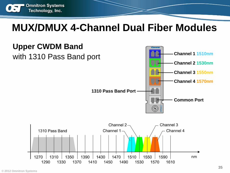
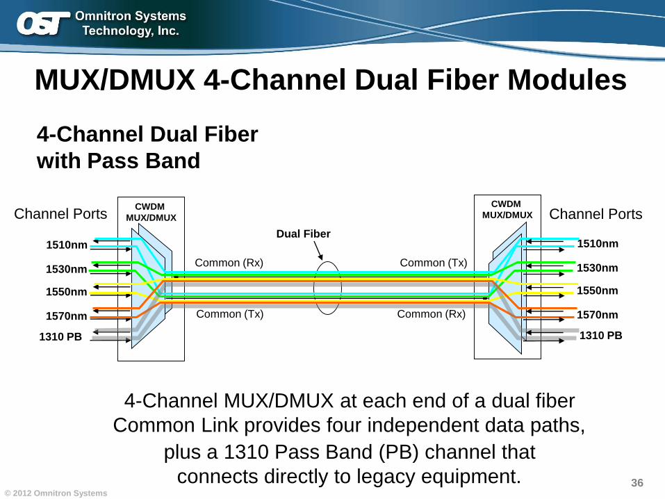
MUX/DMUX 4-Channel Dual Fiber Modules
Upper CWDM Band
with 1310 Pass Band portChannel 1 1510nm
Channel 2 1530nm
Channel 3 1550nm
Channel 4 1570nm
Common Port
36© 2012 Omnitron Systems
CWDM
MUX/DMUXCWDM
MUX/DMUX
1510nm
1530nm
1550nm
1570nm
1310 PB
Channel Ports
MUX/DMUX 4-Channel Dual Fiber Modules
Dual Fiber
Common (Rx)
Common (Tx)
Common (Tx)
Common (Rx)
4-Channel MUX/DMUX at each end of a dual fiber
Common Link provides four independent data paths,
plus a 1310 Pass Band (PB) channel that
connects directly to legacy equipment.
Channel Ports
1510nm
1530nm
1550nm
1570nm
1310 PB
4-Channel Dual Fiber
with Pass Band
37© 2012 Omnitron Systems
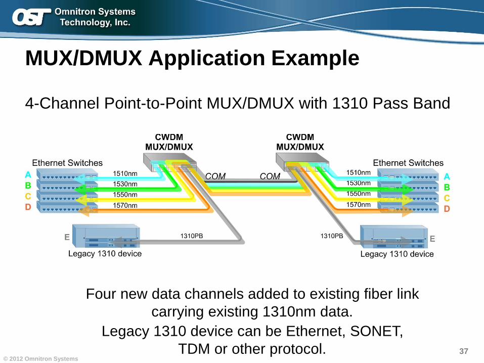
MUX/DMUX Application Example
4-Channel Point-to-Point MUX/DMUX with 1310 Pass Band
Four new data channels added to existing fiber link
carrying existing 1310nm data.
Legacy 1310 device can be Ethernet, SONET,
TDM or other protocol.
38© 2012 Omnitron Systems
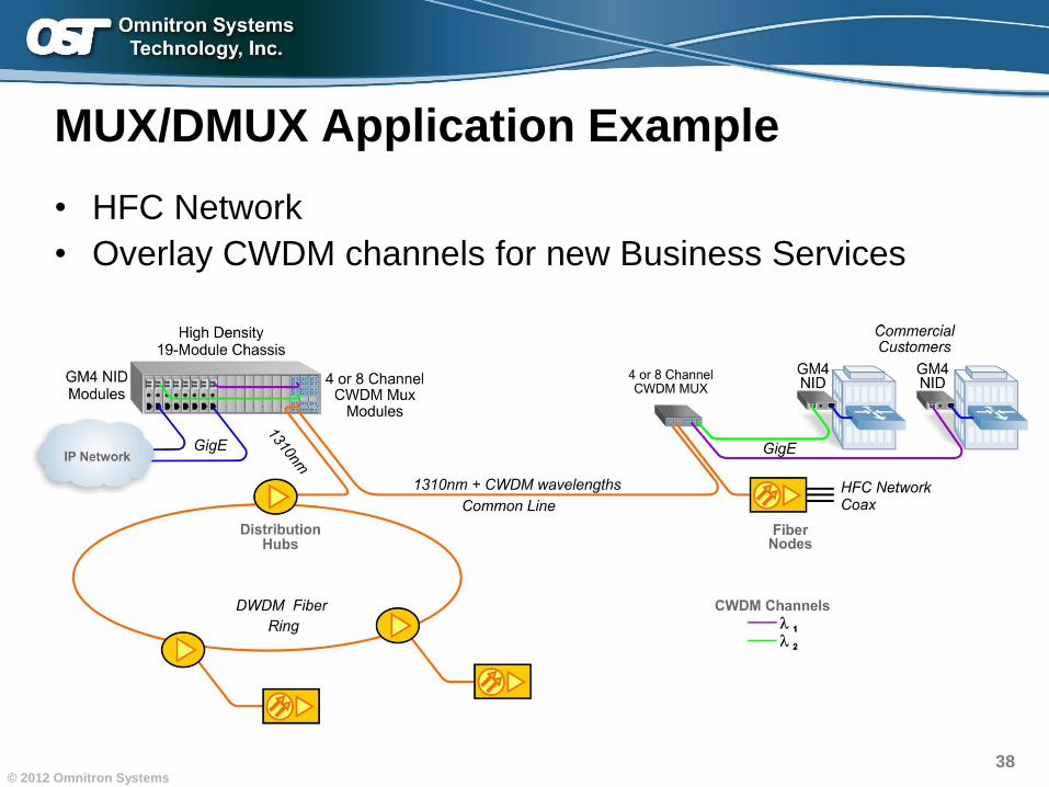
MUX/DMUX Application Example
• HFC Network
• Overlay CWDM channels for new Business Services
39© 2012 Omnitron Systems
1310 Pass Band Port
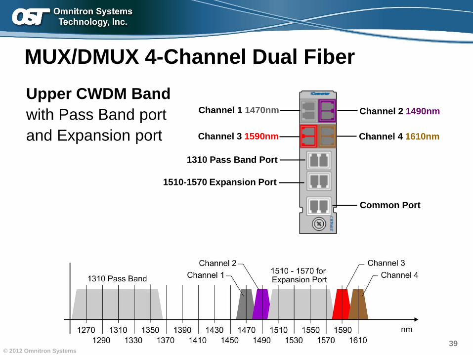
MUX/DMUX 4-Channel Dual Fiber
Upper CWDM Band
with Pass Band port
and Expansion port
Channel 2 1490nm
Channel 4 1610nm
Common Port
Channel 1 1470nm
Channel 3 1590nm
1510-1570 Expansion Port
40© 2012 Omnitron Systems
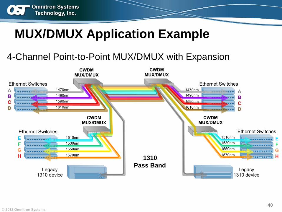
MUX/DMUX Application Example
4-Channel Point-to-Point MUX/DMUX with Expansion
1310
Pass Band
41© 2012 Omnitron Systems
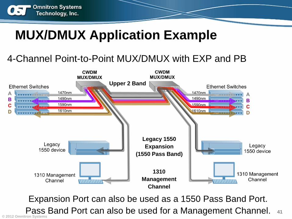
4-Channel Point-to-Point MUX/DMUX with EXP and PB
MUX/DMUX Application Example
Expansion Port can also be used as a 1550 Pass Band Port.
Pass Band Port can also be used for a Management Channel.
Legacy 1550
Expansion
(1550 Pass Band)
Upper 2 Band
1310
Management
Channel
42© 2012 Omnitron Systems
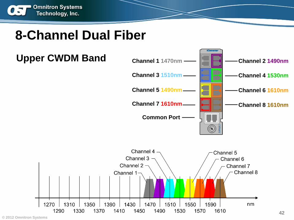
8-Channel Dual Fiber
Upper CWDM Band
Channel 5 1490nm Channel 6 1610nm
Common Port
Channel 1 1470nm Channel 2 1490nm
Channel 7 1610nm
Channel 3 1510nm
Channel 8 1610nm
Channel 4 1530nm
43© 2012 Omnitron Systems
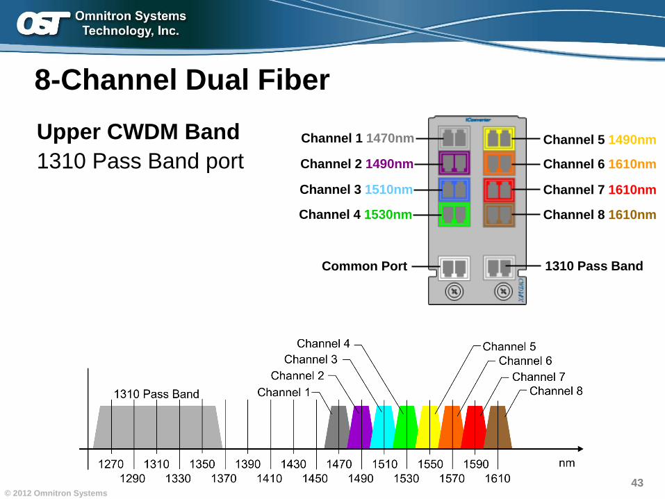
8-Channel Dual Fiber
Upper CWDM Band
1310 Pass Band portChannel 5 1490nm
Channel 6 1610nm
Common Port
Channel 1 1470nm
Channel 2 1490nm
Channel 7 1610nmChannel 3 1510nm
Channel 8 1610nmChannel 4 1530nm
1310 Pass Band
44© 2012 Omnitron Systems
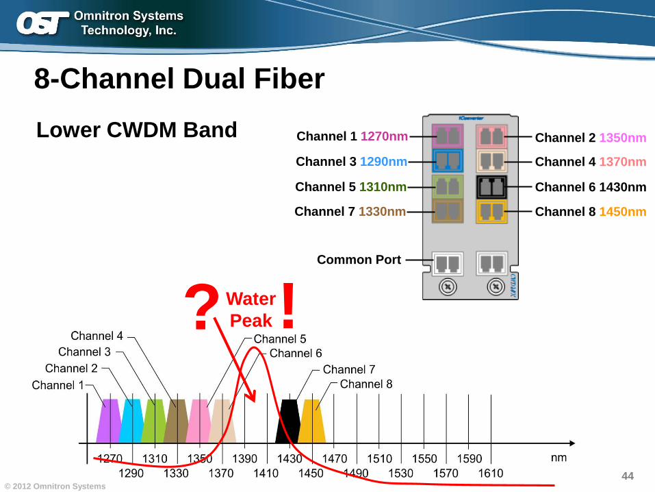
8-Channel Dual Fiber
Lower CWDM Band Channel 2 1350nm
Channel 4 1370nm
Common Port
Channel 1 1270nm
Channel 3 1290nm
Channel 6 1430nmChannel 5 1310nm
Channel 8 1450nmChannel 7 1330nm
?Water
Peak!
45© 2012 Omnitron Systems
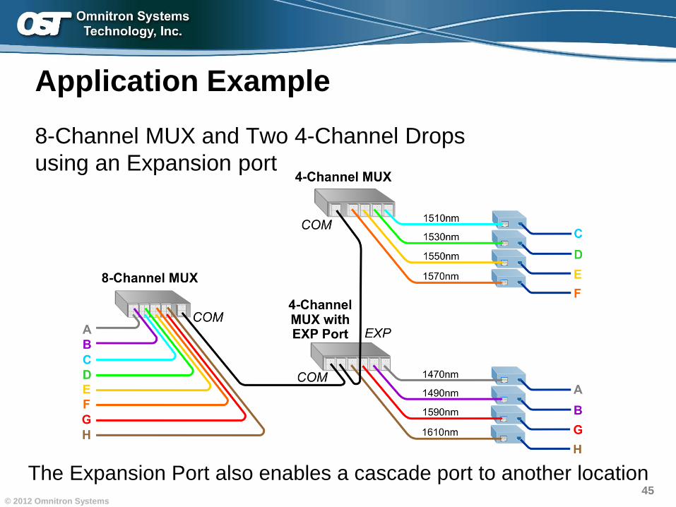
Application Example
8-Channel MUX and Two 4-Channel Drops
using an Expansion port
The Expansion Port also enables a cascade port to another location
46© 2012 Omnitron Systems
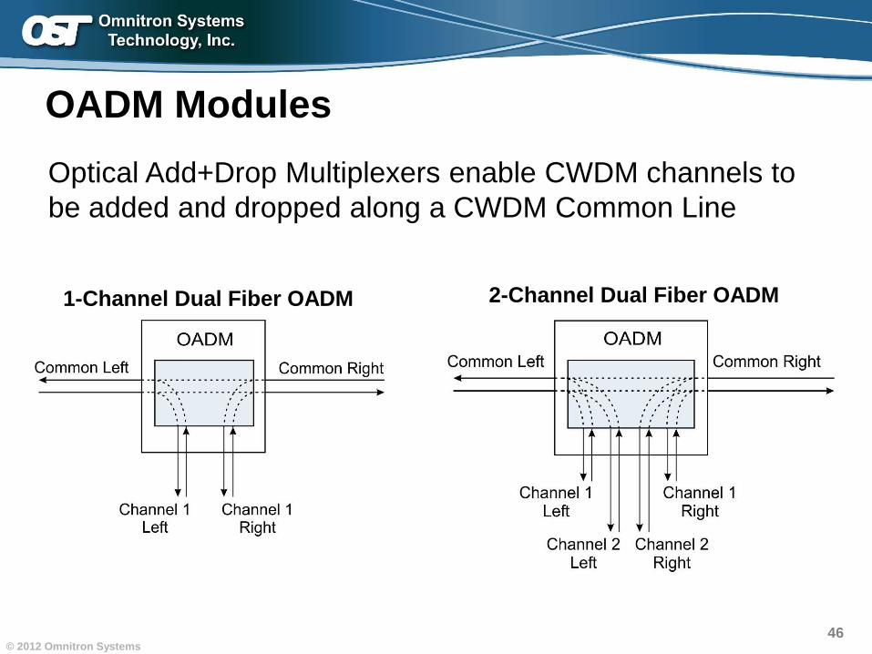
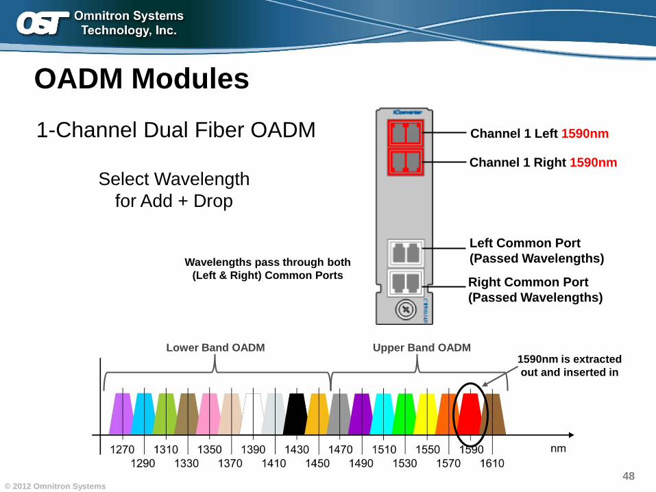
OADM Modules
Optical Add+Drop Multiplexers enable CWDM channels to
be added and dropped along a CWDM Common Line
1-Channel Dual Fiber OADM 2-Channel Dual Fiber OADM
47© 2012 Omnitron Systems
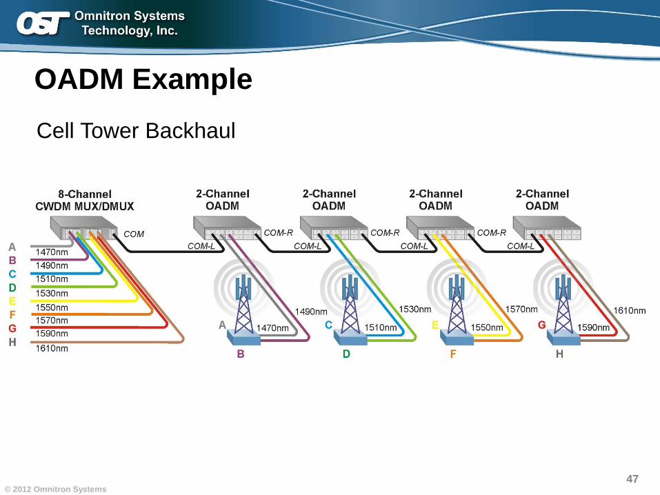
OADM Example
Cell Tower Backhaul
48© 2012 Omnitron Systems
Right Common Port
(Passed Wavelengths)
Channel 1 Left 1590nm
Left Common Port
(Passed Wavelengths)Wavelengths pass through both
(Left & Right) Common Ports
Channel 1 Right 1590nm
OADM Modules
1-Channel Dual Fiber OADM
Select Wavelength
for Add + Drop
1590nm is extracted
out and inserted in
Lower Band OADM Upper Band OADM
49© 2012 Omnitron Systems
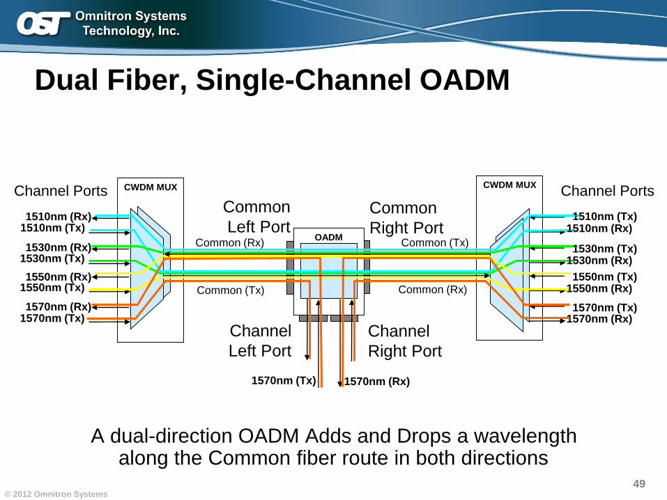
CWDM MUXCWDM MUX
Dual Fiber, Single-Channel OADM
OADM
1570nm (Tx)
1570nm (Rx)
1510nm (Tx)
1530nm (Tx)
1550nm (Tx)
1570nm (Tx)
1510nm (Rx)
1530nm (Rx)
1550nm (Rx)
1570nm (Rx)
Channel Ports
1510nm (Rx)
1530nm (Rx)
1550nm (Rx)
1570nm (Rx)
1510nm (Tx)
1530nm (Tx)
1550nm (Tx)
1570nm (Tx)
Channel Ports
Common (Rx)
Common (Tx)
Common (Tx)
Common (Rx)
1570nm (Tx)
1570nm (Rx)
A dual-direction OADM Adds and Drops a wavelength along the Common fiber route in both directions
Channel
Left Port
Common
Left PortCommon
Right Port
Channel
Right Port
50© 2012 Omnitron Systems
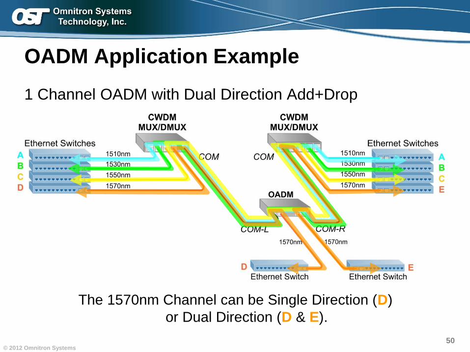
OADM Application Example
1 Channel OADM with Dual Direction Add+Drop
The 1570nm Channel can be Single Direction (D)
E). or Dual Direction (D & E).
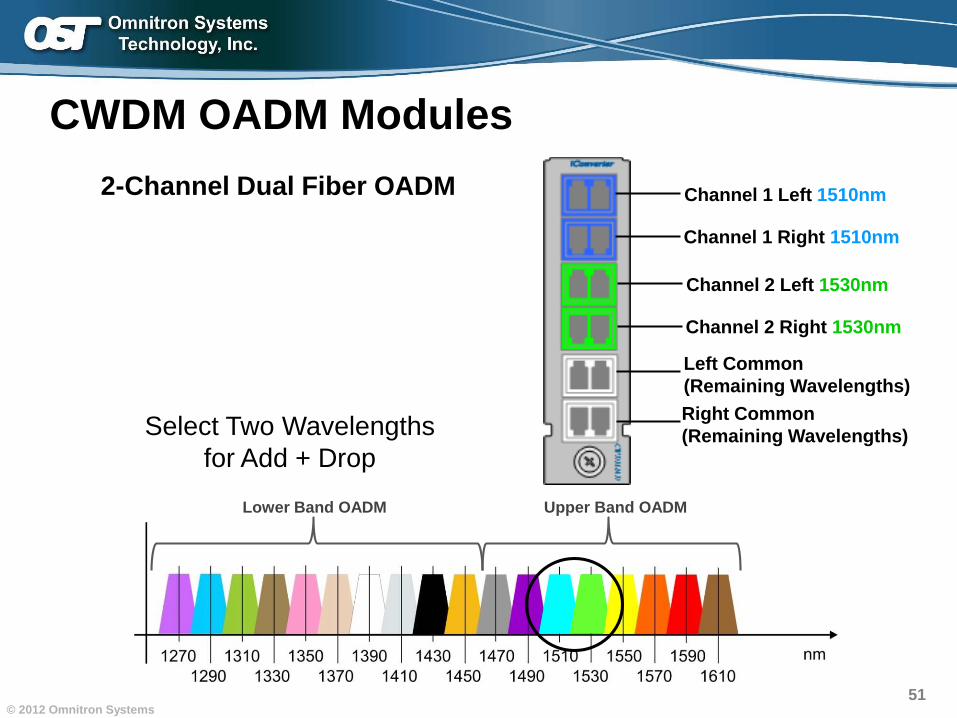
51© 2012 Omnitron Systems
Right Common
(Remaining Wavelengths)
Left Common
(Remaining Wavelengths)
Select Two Wavelengths
for Add + Drop
CWDM OADM Modules
2-Channel Dual Fiber OADM Channel 1 Left 1510nm
Channel 1 Right 1510nm
Channel 2 Left 1530nm
Channel 2 Right 1530nm
Lower Band OADM Upper Band OADM
52© 2012 Omnitron Systems
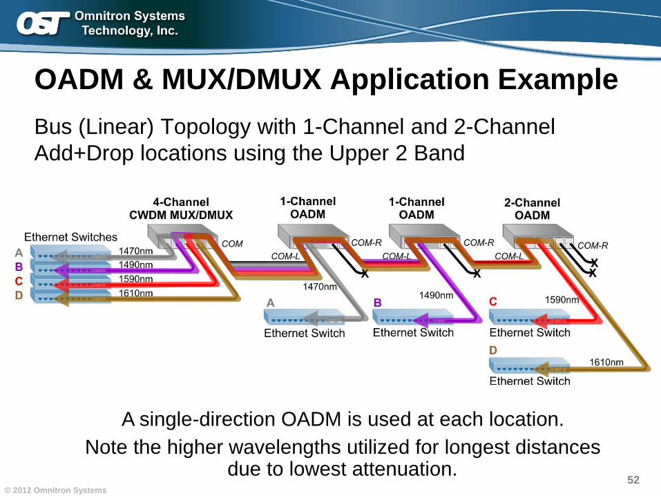
OADM & MUX/DMUX Application Example
Bus (Linear) Topology with 1-Channel and 2-Channel
Add+Drop locations using the Upper 2 Band
A single-direction OADM is used at each location.
Note the higher wavelengths utilized for longest distances due to lowest attenuation.
53© 2012 Omnitron Systems
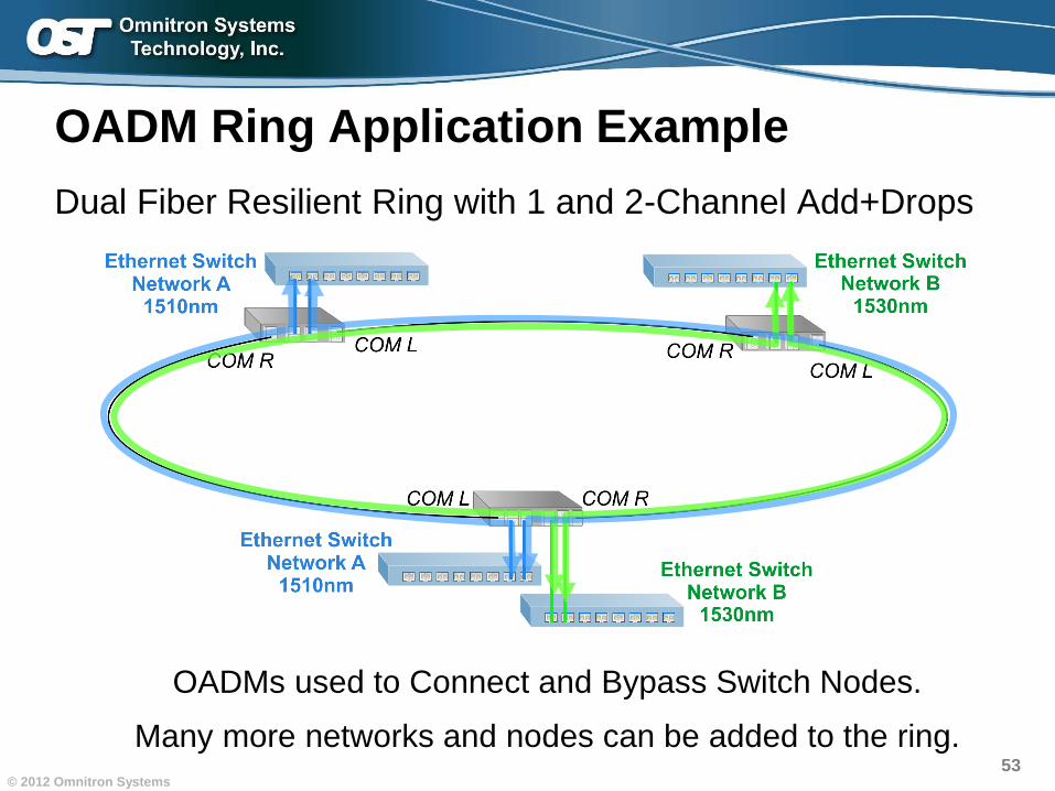
OADM Ring Application Example
Dual Fiber Resilient Ring with 1 and 2-Channel Add+Drops
OADMs used to Connect and Bypass Switch Nodes.
Many more networks and nodes can be added to the ring.
54© 2012 Omnitron Systems
Section Summary
• CWDM is Cost Effective– Much less expensive than upgrading switches and routers
– Maintain investments in existing equipment
• Rapid Deployments– Passive equipment that is easy to use
– Plug and play installations
– No disruption to existing services (Spanning Tree and SONET)
• CWDM Multiplexers Support Dual and Single-Fiber– Single Fiber MUXes support ½ the channels of Dual Fiber.
55© 2012 Omnitron Systems
Section Summary
• Wavelength Band Allocation Provides Design Flexibility– Enables Passing of Standard/Legacy 1310nm and 1550nm
– Complementing Bands for Expansion Ports
– “Workaround” for the 1400nm Water Peak
• MUXes and OADMs Provide Flexible Designs – Add and Drop Linear Bus applications
– Pass Band Ports enable overlaying CWDM onto existing networks
– Overlay Channels on SONET and Resilient Ring networks
– Expansion Ports provide flexibility for future growth
– Expansion Ports also double as 1550 Pass Band,
and enable passing channels to different locations
– Both MUXes and OADMs can be used to Connect and Bypass
Nodes on ring networks
Increasing Fiber Capacity with CWDMIncreasing Fiber Capacity with CWDM
Introduction
WDM Technology Overview
CWDM and Fiber Cabling
Multiplexing Equipment
Application Examples
Wavelength Conversion
Charter Examples
57© 2012 Omnitron Systems
CWDM Wavelength Conversion
OK, CWDM is cool stuff.
But how do I connect my equipment to CWDM MUXes?
• Small Form Pluggable (SFP) transceivers
• Transponders / Wavelength converters
• Media Converters that support SFPs
58© 2012 Omnitron Systems
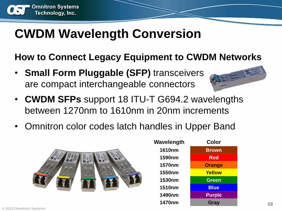
How to Connect Legacy Equipment to CWDM Networks
• Small Form Pluggable (SFP) transceivers
are compact interchangeable connectors
• CWDM SFPs support 18 ITU-T G694.2 wavelengths
between 1270nm to 1610nm in 20nm increments
• Omnitron color codes latch handles in Upper Band
CWDM Wavelength Conversion
Wavelength Color
1610nm Brown
1590nm Red
1570nm Orange
1550nm Yellow
1530nm Green
1510nm Blue
1490nm Purple
1470nm Gray
59© 2012 Omnitron Systems
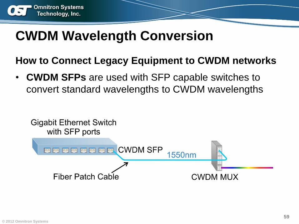
How to Connect Legacy Equipment to CWDM networks
• CWDM SFPs are used with SFP capable switches to
convert standard wavelengths to CWDM wavelengths
CWDM Wavelength Conversion
60© 2012 Omnitron Systems
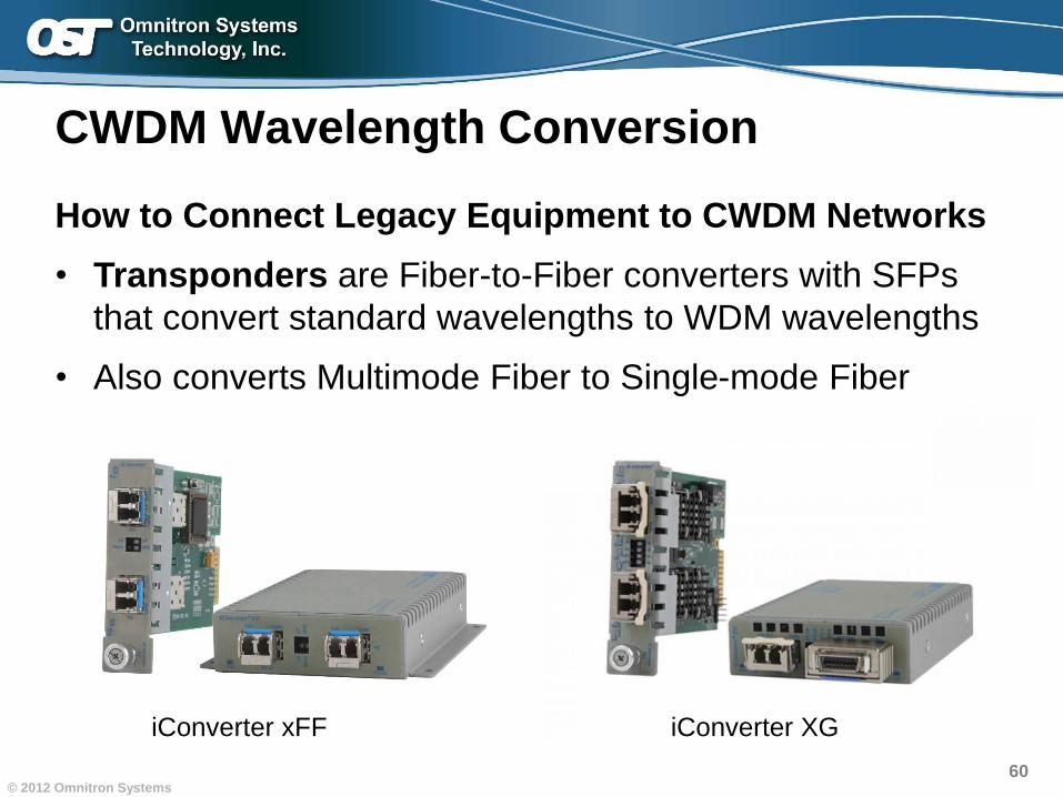
CWDM Wavelength Conversion
How to Connect Legacy Equipment to CWDM Networks
• Transponders are Fiber-to-Fiber converters with SFPs
that convert standard wavelengths to WDM wavelengths
• Also converts Multimode Fiber to Single-mode Fiber
iConverter xFF iConverter XG
61© 2012 Omnitron Systems
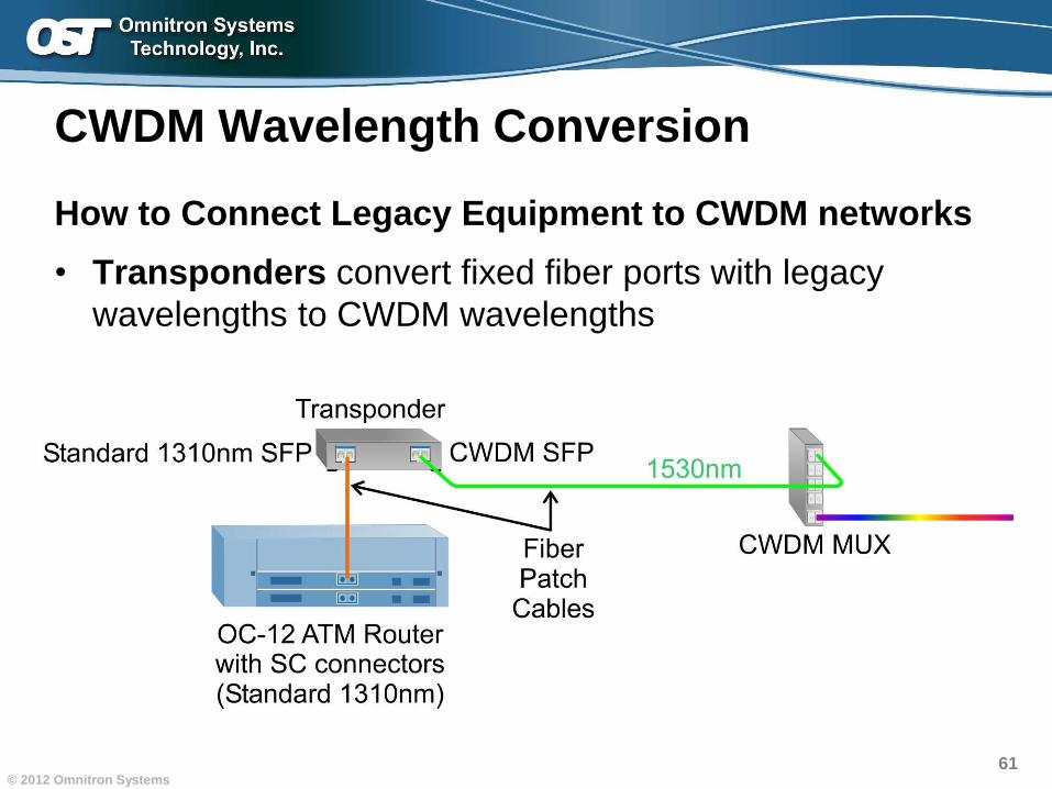
CWDM Wavelength Conversion
How to Connect Legacy Equipment to CWDM networks
• Transponders convert fixed fiber ports with legacy
wavelengths to CWDM wavelengths
62© 2012 Omnitron Systems
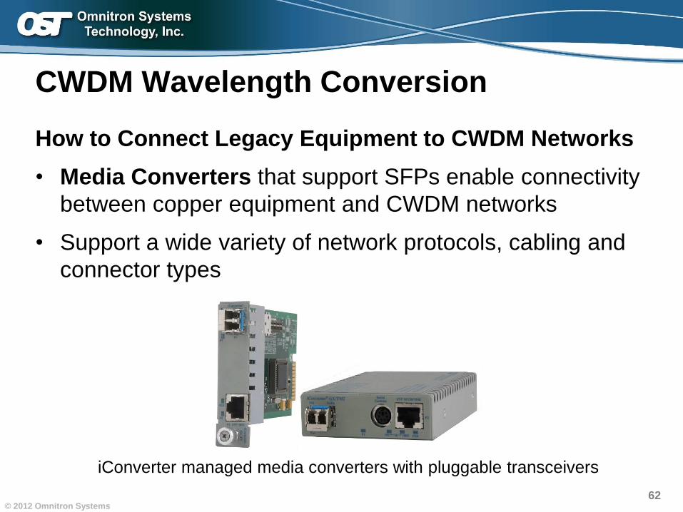
CWDM Wavelength Conversion
How to Connect Legacy Equipment to CWDM Networks
• Media Converters that support SFPs enable connectivity
between copper equipment and CWDM networks
• Support a wide variety of network protocols, cabling and
connector types
iConverter managed media converters with pluggable transceivers
63© 2012 Omnitron Systems
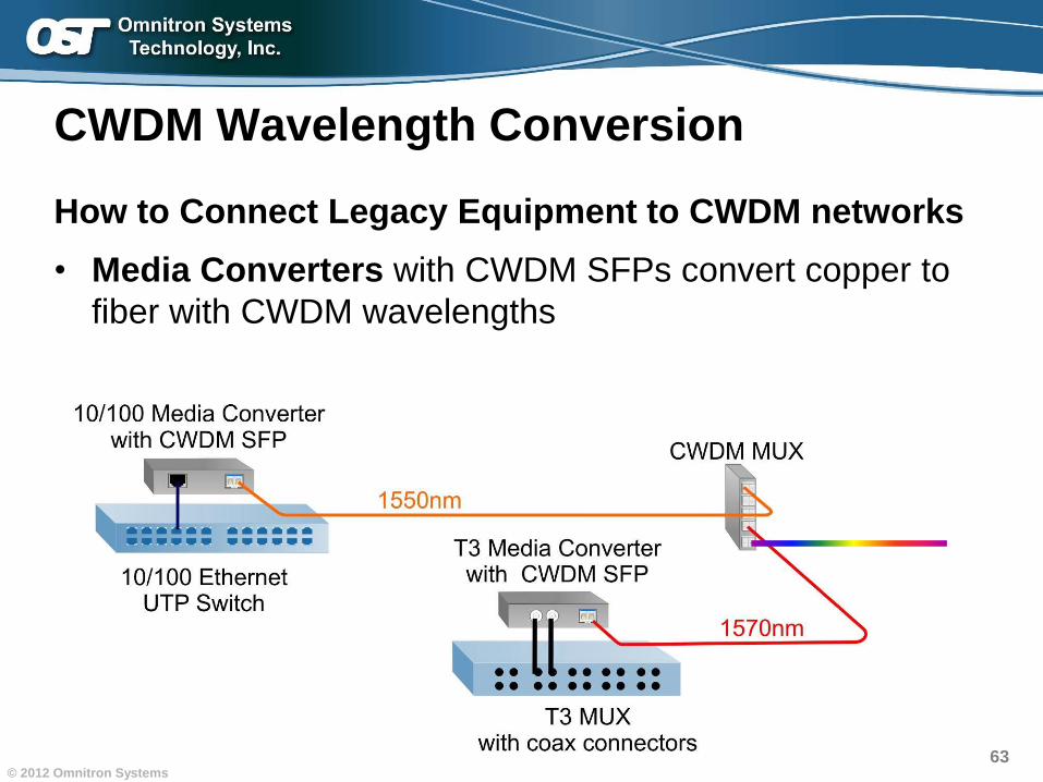
CWDM Wavelength Conversion
How to Connect Legacy Equipment to CWDM networks
• Media Converters with CWDM SFPs convert copper to
fiber with CWDM wavelengths
64© 2012 Omnitron Systems
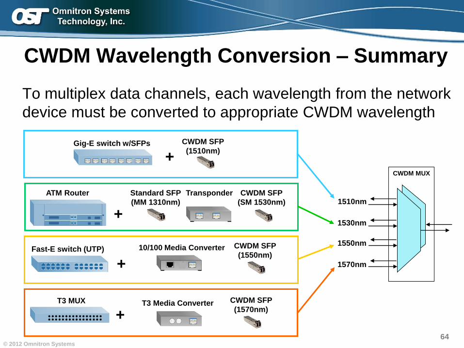
CWDM Wavelength Conversion – Summary
To multiplex data channels, each wavelength from the network
device must be converted to appropriate CWDM wavelength
CWDM MUX
1510nm
1530nm
1550nm
1570nm
+
Transponder CWDM SFP
(SM 1530nm)
ATM Router Standard SFP
(MM 1310nm)
+Fast-E switch (UTP) 10/100 Media Converter CWDM SFP
(1550nm)
CWDM SFP
(1510nm)+
Gig-E switch w/SFPs
T3 MUX
+T3 Media Converter CWDM SFP
(1570nm)
Increasing Fiber Capacity with CWDMIncreasing Fiber Capacity with CWDM
Introduction
WDM Technology Overview
CWDM and Fiber Cabling
Multiplexing Equipment
Application Examples
Wavelength Conversion
Charter Examples
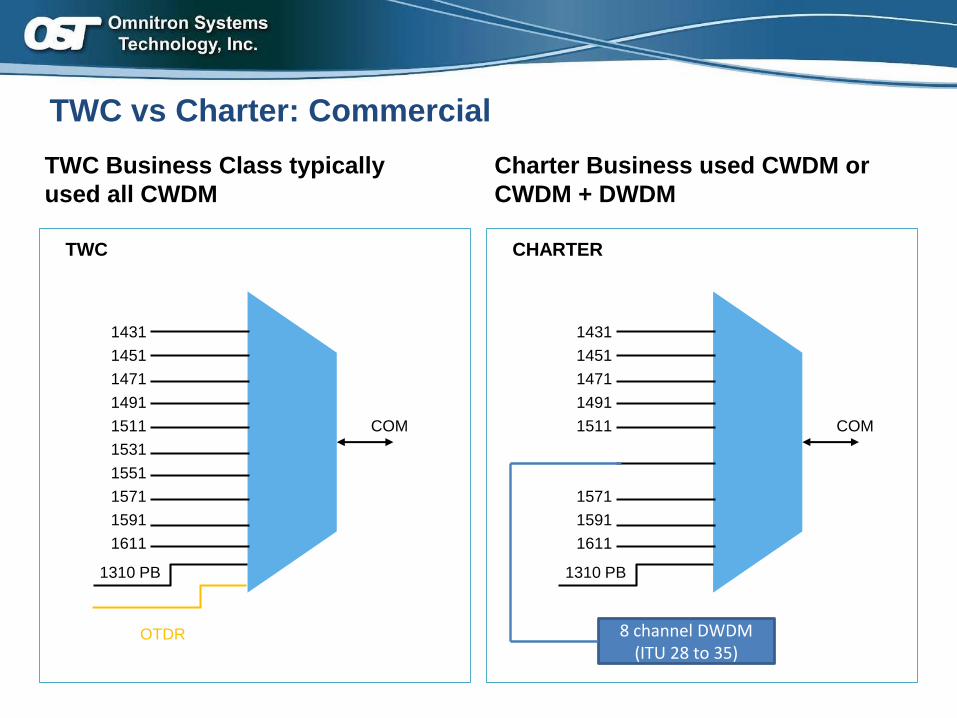
TWC vs Charter: Commercial
TWC CHARTER
1431
1451
1471
1491
1511
1531
1551
1571
1591
1611
1310 PB
COM
OTDR
1431
1451
1471
1491
1511
1571
1591
1611
1310 PB
COM
8 channel DWDM (ITU 28 to 35)
TWC Business Class typically
used all CWDM
Charter Business used CWDM or
CWDM + DWDM
67 Proprietary and Confidential © 2017 Omnitron Systems
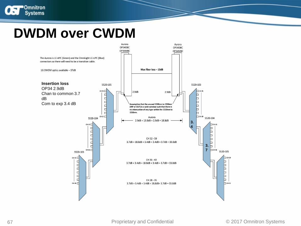
DWDM over CWDM
3.
4
3.
7
Insertion loss
OP34 2.9dB
Chan to common 3.7
dB
Com to exp 3.4 dB
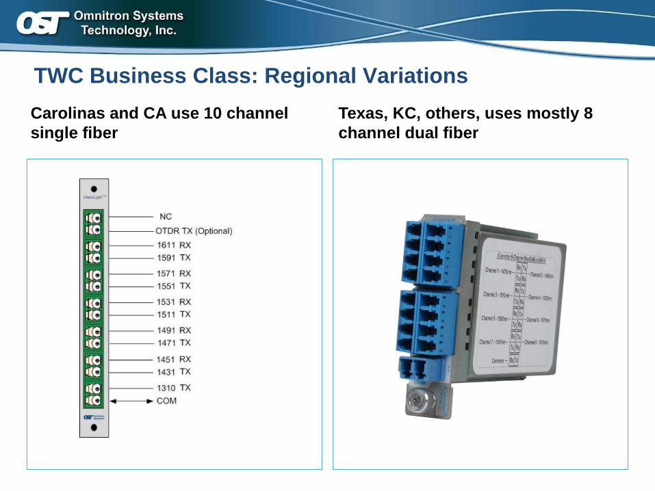
TWC Business Class: Regional Variations
Carolinas and CA use 10 channel
single fiber
Texas, KC, others, uses mostly 8
channel dual fiber
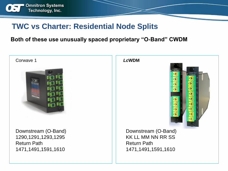
TWC vs Charter: Residential Node Splits
Corwave 1 LcWDM
Downstream (O-Band)
1290,1291,1293,1295
Return Path
1471,1491,1591,1610
Downstream (O-Band)
KK LL MM NN RR SS
Return Path
1471,1491,1591,1610
Both of these use unusually spaced proprietary “O-Band” CWDM
Omnitron Product SlidesOmnitron Product Slides
71© 2012 Omnitron Systems
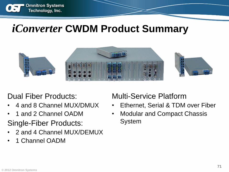
iConverter CWDM Product Summary
Dual Fiber Products:• 4 and 8 Channel MUX/DMUX
• 1 and 2 Channel OADM
Single-Fiber Products:• 2 and 4 Channel MUX/DEMUX
• 1 Channel OADM
Multi-Service Platform• Ethernet, Serial & TDM over Fiber
• Modular and Compact Chassis
System
72© 2012 Omnitron Systems
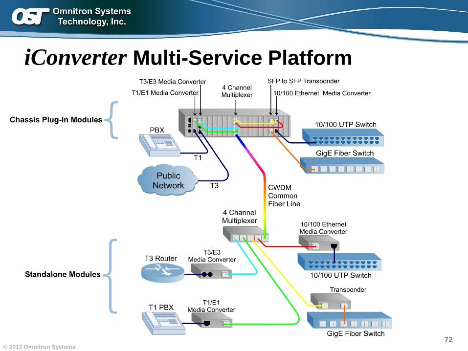
iConverter Multi-Service Platform
73© 2012 Omnitron Systems
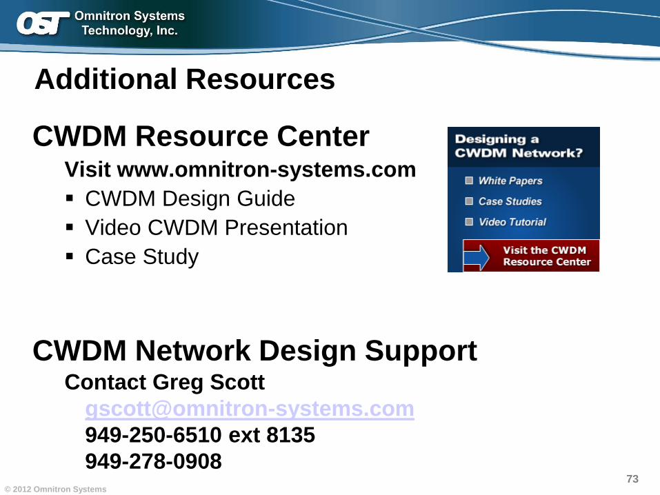
CWDM Resource CenterVisit www.omnitron-systems.com
▪ CWDM Design Guide
▪ Video CWDM Presentation
▪ Case Study
CWDM Network Design SupportContact Greg Scott
949-250-6510 ext 8135
949-278-0908
Additional Resources
74© 2012 Omnitron Systems
USA
Phone: 949-250-6510, Ext. 8135
Toll Free: 800-675-8410
Email [email protected]
Web www.omnitron-systems.com
Omnitron SystemsSales and Support Contact Information
Q and A


![Components Filter CWDM Mini-CWDM Module · CWDM 8-channel CWDM 8+1-channel CWDM Parameter Value Value Center wavelength CWDM channels (1) [nm] custom-made custom-made Channel spacing](https://img.pdfslide.net/doc/110x75/5fe9006edd33a81f82202f75/components-filter-cwdm-mini-cwdm-cwdm-8-channel-cwdm-81-channel-cwdm-parameter.jpg)