Embed Size (px)
Citation preview
The Magazine for ENERGY EFFICIENCY in Blower and Vacuum Systems
Apri
l 201
7
6 Blow
er & Va
cuum
Tech
Pick
s
kW
CO2
INDUSTRIAL VACUUM & BLOWER SYSTEMS
13 Integrity Test Solutions for the Pharmaceutical Industry
16 The Heart of Pneumatic Conveying – PD Blower Calculations
20 Vacuum System Fundamentals for “Compressed Air People”
AERATION BLOWER SYSTEMS
25 Busch Provides Reliable Oxygen Supply to Aeration Tanks
Don’t Settle for Less than the Best
Energy is the single highest operating cost in a wastewater treatment plant and 60% of a plant’s energy costs are spent on aeration. At Kaeser, we’ve been providing efficient aeration solutions for many years.
Kaeser’s Sigma screw blower packages are 35% more efficient than conventional blower designs. In addition to exceptional efficiency, our screw blower packages are designed and built from the ground up for reliability and service accessibility. They come complete with motors, starters/drives, silencers, an onboard controller, and a full complement of sensors to save you time and money on design and installation costs.
If you’re looking for reliability and efficiency, talk to Kaeser and get the best.
COMPRESSORSka
ese
r.c
om The best efficiency. The quietest operation. The highest savings.
Kaeser Compressors, Inc. • 866-516-6888 • us.kaeser.com/BVBPBuilt for a lifetime is a trademark of Kaeser Compressors, Inc. ©2017 Kaeser Compressors, Inc. [email protected]
AERATION BLOWER SYSTEMS
COLUMNS
13 Integrity Test Solutions for the Pharmaceutical Industry By Dennis Seibert and Philippe Bunod, Pfeiffer Vacuum
16 The Heart of Pneumatic Conveying Systems – Positive Displacement Blower Calculations By Roger E. Blanton, P.E., Howden Roots
20 Vacuum System Fundamentals for “Compressed Air People” By Tim Dugan, P.E., Compression Engineering Corporation
25 Busch Provides Reliable Oxygen Supply to Aeration Tanks By Uli Merkle, Busch Vacuum Pumps and Systems
4 From the Editor
6 Resources for Energy Engineers Technology Picks
28 Blower & Vacuum System Industry News
33 Advertiser Index
INDUSTRIAL VACUUM & BLOWER SYSTEMS
16
13
25
3 blowervacuumbestpractices.com
COLUMNS A P R I L 2 0 1 7 | V O L U M E 3 , N O . 2 |
Pfeiffer Vacuum has over fifty years of experience assisting the
pharmaceutical industry with highly sensitive leak detection and integrity
test solutions. Dennis Seibert and Philippe Bunod have provided us with
an interesting article detailing advances in testing technology to ensure
drug stability by protecting it from contaminants such as humidity, oxygen
or microbiological ingress.
Dilute phase pneumatic conveying is widely used in the pharmaceutical industry. Pressures do not
exceed 15 psig as the material is held in suspension throughout the pipeline. Roger Blanton, P.E.,
from Howden Roots, has provided us with a useful article about limitations, capacity control,
and sizing calculations for “the heart” of the conveying system – the positive displacement blower.
It’s an exciting time for industrial vacuum systems as Energy Managers study which of
the optimization techniques they used to optimize compressed air systems (such as VFD,
centralization, demand reduction) can be applied to their “rough” vacuum systems. Tim Dugan,
P.E., has written a very useful article titled, “Vacuum System Fundamentals for Compressed Air
People”. In it he reviews what changes and what doesn’t, what is controlled, and how to design
vacuum systems for optimal energy consumption.
Busch Vacuum Pumps & Systems is a market leader in many segments, such as food packaging
and processing. What may not be as well known, here in North America, is their involvement
with wastewater aeration systems. Uli Merkle provides us with an interesting application story,
where their Tyr rotary lobe blowers provide reliable aeration for a treatment facility operated
by the Wastewater Association of Rheinfelden-Schwoerstadt in Germany.
Thank you for investing your time and efforts into Blower & Vacuum Best Practices.
ROD SMITH Editor tel: 412-980-9901, [email protected]
FROM THE EDITOR
2017 MEDIA PARTNERS
BLOWER & VACUUM BEST PRACTICES
EDITORIAL ADVISORY BOARD
Indus
trial
Ener
gy M
anag
ers
Doug Barndt Manager, Demand Side Energy-Sustainability
Ball Corporation
Richard Feustel Senior Energy Advisor Leidos
Thomas SullivanEnergy Performance Manager
Michelin
William Jerald Energy Manager CalPortland
Jennifer MeierGlobal EH&S/ Plant Engineering Manager
Varroc Lighting Systems
Thomas Mort Senior Auditor Thomas Mort Consulting
Brad Reed Corporate Energy Team Leader Toyota
Brad Runda Global Director, Energy Koch Industries
Uli Schildt Energy Engineer Darigold
Don Sturtevant Corporate Energy Manager Simplot
Bryan Whitfield Paint & Powder Booth Specialist
Fiat Chrysler Automotive US
2017 Expert Webinar SeriesJoin Tom Jenkins and Sponsor Kaeser Compressors, on May 11th, for a Webinar titled, “Blower Controls for Aeration Efficiency.”
Register and view our 2017 Webinar Calendar at www.blowervacuumbestpractices.com/magazine/webinars.
| 0 4 / 1 7
4 blowervacuumbestpractices.com
COLUMNS
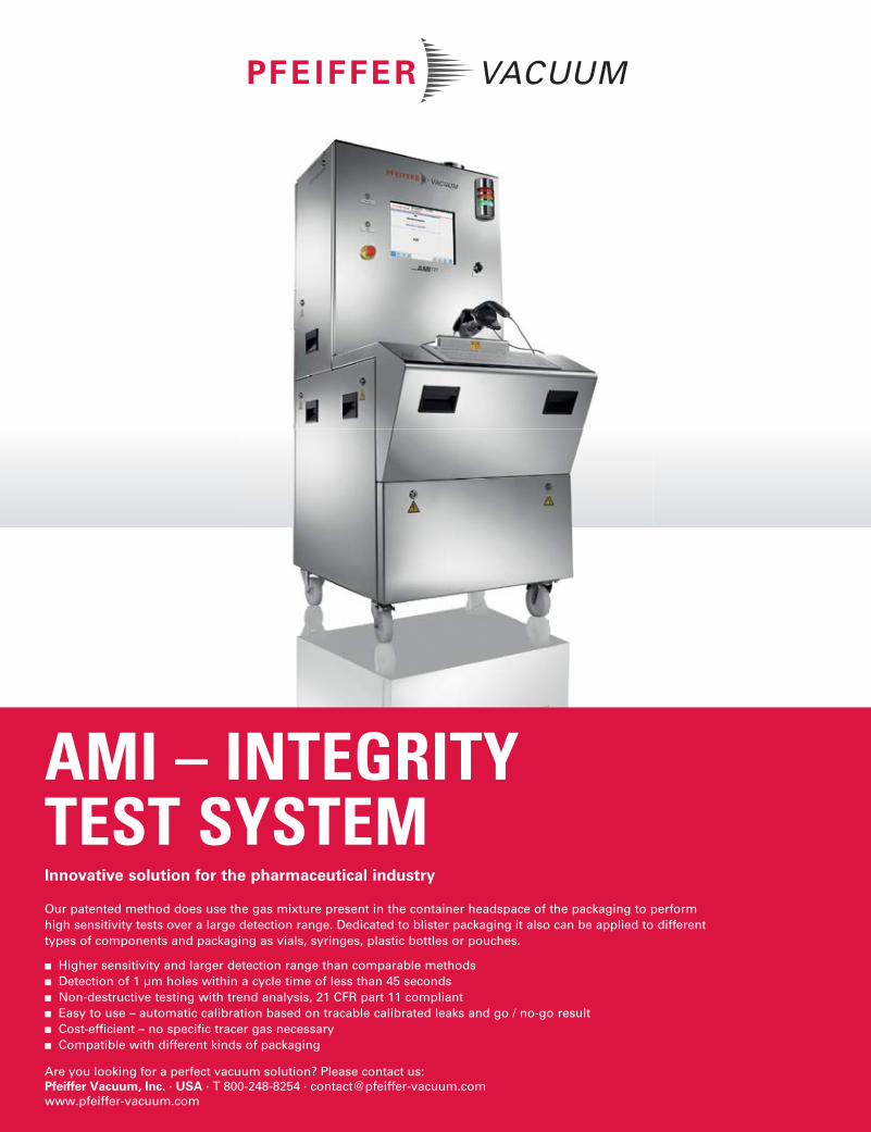
Our patented method does use the gas mixture present in the container headspace of the packaging to perform high sensitivity tests over a large detection range. Dedicated to blister packaging it also can be applied to different types of components and packaging as vials, syringes, plastic bottles or pouches.
■ Higher sensitivity and larger detection range than comparable methods
■ Detection of 1 µm holes within a cycle time of less than 45 seconds
■ Non-destructive testing with trend analysis, 21 CFR part 11 compliant
■ Easy to use – automatic calibration based on tracable calibrated leaks and go / no-go result
■ Cost-efficient – no specific tracer gas necessary
■ Compatible with different kinds of packaging
AMI – INTEGRITYTEST SYSTEMInnovative solution for the pharmaceutical industry
Are you looking for a perfect vacuum solution? Please contact us:Pfeiffer Vacuum, Inc. · USA · T 800-248-8254 · [email protected] www.pfeiffer-vacuum.com
17.02.27_BlowerVacuum_April_AMI121_212,75x276,25mm_EN.indd 1 27.02.17 14:41
Leybold ECODRY plus – the laboratory whisperer
The requirements for modern analytical
instruments and systems are changing:
users in laboratories and research facilities
increasingly rely on low-noise, oil-free
vacuum solutions to avoid contamination
and, above all, unnecessary noise in
laboratory environments. With the newly
developed family of dry-compressing multi-
stage Roots vacuum pump ECODRY plus,
Leybold has now launched a new fore-
vacuum pump for the analytics market. The
most striking competitive advantages: apart
from its quiet and low-vibration operation, it
features a modern, space-saving design with
extremely powerful performance.
The basic idea of the ECODRY plus was
to develop a clean, compact and low-
maintenance pump in the size class 40 to
60 m3 / h, as used in analytical or research
laboratories. This pump class is positioned
exactly in the transition area between small
laboratory equipment and large machines.
The most important innovation, however,
is undoubtedly the reduction in the noise
level that the Leybold developers were able
to achieve: “We have managed to build the
pump as compact, easy to operate and quiet
as is otherwise known only from much
smaller devices”, explains the responsible
product manager, Alexander Kaiser, the
positioning features of this novelty.
The ECODRY plus was developed to match
the requirements for systems such as mass
spectrometers and electron microscopes. It is
also suitable for large-scale accelerators due
to the absence of dust or oil contamination.
It offers a high degree of comfort, suction
power and flexibility. The pump family,
available in the sizes 40 plus and 65 plus,
offers short delivery times and can also be
obtained via the Leybold Online Shop.
The most important feature of this new
vacuum pump range is the extremely low
noise level. With an average value of 52
dB (A), it works below the noise limit
that is harmful to human health. The
sound level of the ECODRY plus is below a
conversation at room volume. In every day
operation and compared to the relevant
competitive products of its class, the pump,
which is designed for ergonomic working
environments, yields the lowest noise
emissions.
Such low values are the result of an
ingenious development and construction
strategy. Integrated into the pump housing,
the ECODRY offers sound insulation, an
optimized silencer in the exhaust and a quiet
air cooling system. At Leybold, the insulation
is installed as standard.
The non-contact rotor design is not only
designed for a whisper-quiet operation,
but also for energy-efficiency and low
vibration. In order to be able to produce
high-resolution images, such as in electron
and scanning tunnel microscopes, the pump
must not transmit vibrations. The elementary
feature is that the rotors and the housing
rotate without friction even at high speeds of
up to 12600 min-1. In addition, as measured
by industry-standard solutions, it generates
less heat, which means lower operating costs
for air-conditioning.
In class comparison, the ECODRY plus is also
one of the lightest and most compact vacuum
components. Users appreciate this feature, as
systems for research and development have
to deliver their performance in a narrow
space. Concerning performance, this pump
range was designed to deliver what is needed
for the relevant applications. “This is why
we were able to design compact mechanical
components and use a smaller motor and
smaller electronic components”, says
Alexander Kaiser.
The lubrication takes place only in the
area of the bearing of the shafts, which
are separated from the pump chamber by
a wear-free sealing system. Thus, neither
lubricant nor particles penetrate into the
pump chamber and the recipient, thereby
causing no deterioration of the final pressure
or suction. This, in turn, results in only
occasional maintenance, as appreciated in
ultrahigh-vacuum applications. Users can
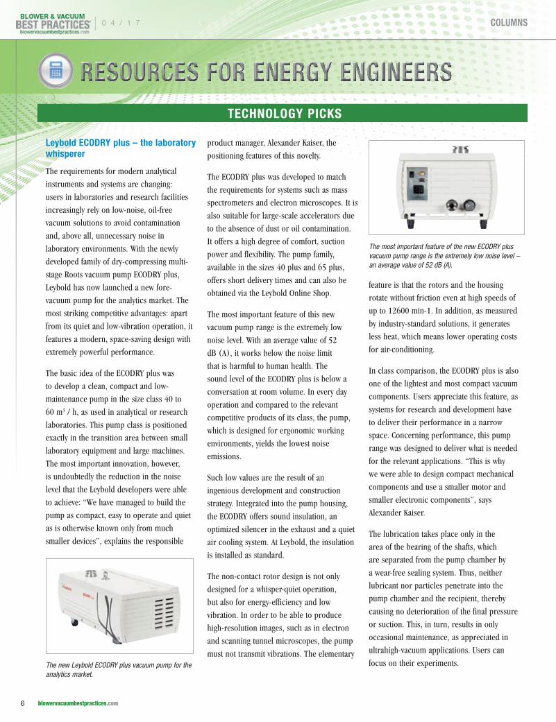
focus on their experiments.The new Leybold ECODRY plus vacuum pump for the analytics market.
The most important feature of the new ECODRY plus vacuum pump range is the extremely low noise level – an average value of 52 dB (A).
RESOURCES FOR ENERGY ENGINEERSTECHNOLOGY PICKS
| 0 4 / 1 7
6 blowervacuumbestpractices.com
COLUMNS
Equipped with two flexible interfaces, the pump can also be
remotely controlled. When used in commercial analysis systems,
the pump is frequently integrated into the plant control system, and
started, stopped, speed-varied and monitored as required.
With the ECODRY plus from Leybold, a new optimized product
is launched, which is unrivaled quiet and meets the increasing
performance requirements of the applications.
About Leybold
Leybold is a part of the Vacuum Solution Division within
the Atlas Copco’s Compressor Technique business area and
offers a broad range of advanced vacuum solutions for use in
manufacturing and analytical processes, as well as for research
purposes. The core capabilities center on the development of
application- and customer-specific systems for the creation of
vacuums and extraction of processing gases. Fields of application
are secondary metallurgy, heat treatment, automotive industry,
coating technologies, solar and thin films such as displays,
research & development, analytical instruments, as well as classic
industrial processes.
About Atlas Copco
Atlas Copco is a world-leading provider of sustainable productivity
solutions. The Group serves customers with innovative
compressors, vacuum solutions and air treatment systems,
construction and mining equipment, power tools and assembly
systems. Atlas Copco develops products and services focused on
productivity, energy efficiency, safety and ergonomics. The company
was founded in 1873, is based in Stockholm, Sweden, and has a
global reach spanning more than 180 countries. In 2016, Atlas
Copco had revenues of 11 Billion Euros and more than 45 000
employees.
Since 1952, Atlas Copco is present in Germany. Under the roof of
two holdings located in Essen, more than 20 production and sales
companies are gathered (February 2017). By end of 2016, the
group employed about 3800 people, including about 100 trainees.
www.atlascopco.de
To learn more about Leybold, please visit www.leybold.com
TECHNOLOGY PICKS
0 4 / 1 7 |
7 blowervacuumbestpractices.com
COLUMNS
RESOURCES FOR ENERGY ENGINEERS
Pfeiffer Vacuum Introduces New Magnetically Coupled Rotary Vane Pump
The Duo 11 ATEX rotary vane pump, which
meets ATEX directive 2014/34/EU, was
brought to the market by Pfeiffer Vacuum
for processes taking place in potentially
explosive atmospheres or conveying explosive
gases and vapors. It satisfies the most
stringent explosion protection requirements.
The ATEX certification applies for both the
interior and exterior of the pump. The Duo
11 ATEX is classified as equipment category
3G and temperature class T4. It can convey all
gases up to and including explosion group IIC.
The pumping speed is 9 m³/h at 50 Hz
and 10.5 m³/h at 60 Hz. The Duo 11 ATEX
is equipped with a frictionless magnetic
coupling. The shaft seal rings that are
used with other rotary vane pumps can be
dispensed with as a result. The extra safety,
which the magnetic coupling provides, is
important in explosive atmospheres and
without shaft seal rings, it is impossible for
media inside the pump to escape out through
faulty shaft seal rings.
Explosion-proof equipment is required
in many types of applications: potentially
explosive gases are used in numerous
industrial processes. Hazardous gas
atmospheres are present in applications such
as research experiments, various industrial
processes, biotechnology, and chemistry
laboratories. Gas filling machines are also
vulnerable to a massive risk of explosion. The
new Duo 11 ATEX from Pfeiffer Vacuum can
be used in all of these applications.
About Pfeiffer Vacuum
Pfeiffer Vacuum is one of the world’s leading
providers of vacuum solutions. In addition
to a full range of hybrid and magnetically
levitated turbopumps, the product portfolio
comprises backing pumps, leak detectors,
measurement and analysis devices,
components, as well as vacuum chambers
and systems. Ever since the invention of the
turbopump by Pfeiffer Vacuum, the company
has stood for innovative solutions and high-
tech products that are used in the Analytics,
Industry, Research & Development, Coating
and Semiconductor markets. Founded in
1890, Pfeiffer Vacuum is active throughout
the world today. The company employs a
workforce of some 2,350 people and has
more than 20 subsidiaries.
For more information, please visit www.pfeiffer-vacuum.com.
New Busch Zebra RH Vacuum Pumps for Laboratories and Production
Busch Vacuum Pumps and Systems has now
launched a new series of vacuum pumps for a
wide range of applications. The new two-stage
oil-lubricated rotary vane vacuum pumps
Zebra RH were developed both for research
laboratories and for production processes
that work in the medium vacuum range.
Robustness and reliability of operation are
the outstanding qualities of Zebra RH rotary
vane vacuum pumps. The proven rotary vane
vacuum technology from Busch has long
established itself as the industry standard
in the rough vacuum range. With the new
series, Busch is now making inroads in the
medium vacuum range. All Zebra RH sizes
achieve ultimate pressures <0.0076 hPa
(mbar). The series includes eight sizes and
covers pumping speeds from 2.4 to 90 m3/h.
Zebra RH vacuum pumps are thus also highly
suitable as backing pumps for turbomolecular
vacuum pumps and can be used in this
combination in the high vacuum range.
The consistently high vacuum level in
continuous operation is ensured by forced
oil lubrication, perfectly coordinated
materials as well as state-of-the-art precision
manufacturing. Its silent operation makes
the Zebra vacuum pump series perfectly
suited for use in research labs, where a low-
noise working environment is essential. The
advanced design ensures that only minimal
maintenance is required.
A gas ballast valve, that can be manually
switched on and off makes it possible to
handle gasses with high water vapor load.
Some of the application areas are mass
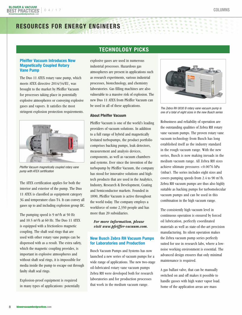
Pfeiffer Vacuum magnetically coupled rotary vane pump with ATEX certification
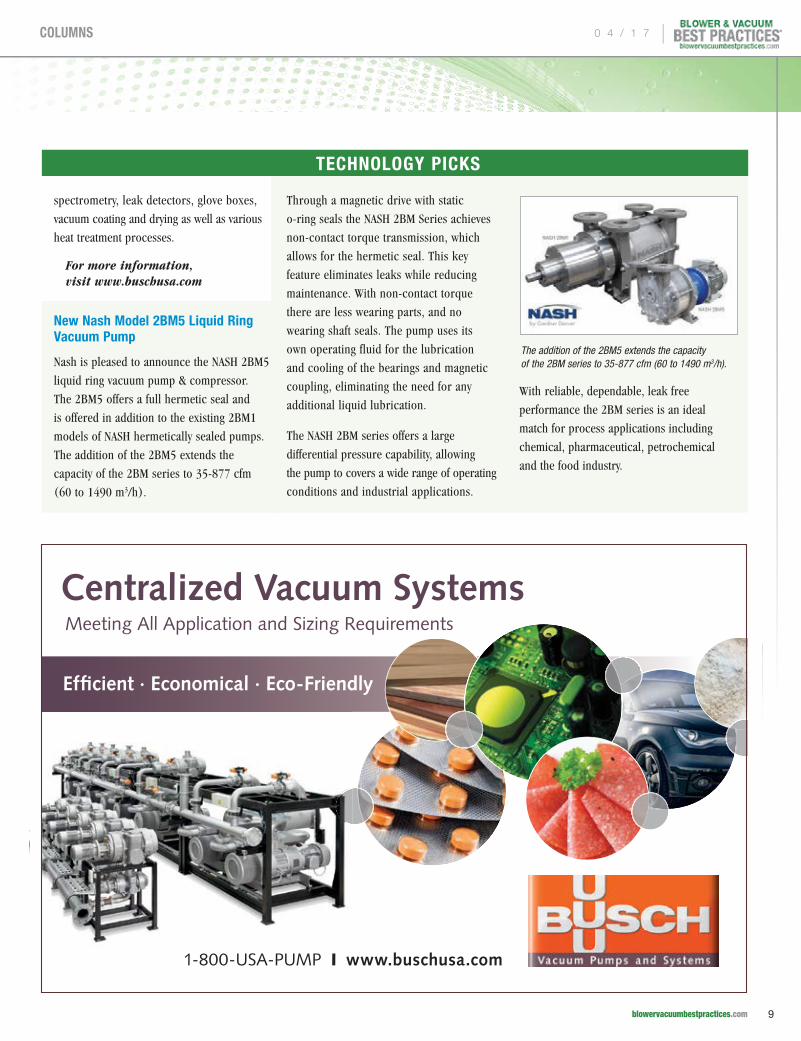
The Zebra RH 0030 B rotary vane vacuum pump is one of a total of eight sizes in the new Busch series
TECHNOLOGY PICKS
| 0 4 / 1 7
8 blowervacuumbestpractices.com
COLUMNS
spectrometry, leak detectors, glove boxes,
vacuum coating and drying as well as various
heat treatment processes.
For more information, visit www.buschusa.com
New Nash Model 2BM5 Liquid Ring Vacuum Pump
Nash is pleased to announce the NASH 2BM5
liquid ring vacuum pump & compressor.
The 2BM5 offers a full hermetic seal and
is offered in addition to the existing 2BM1
models of NASH hermetically sealed pumps.
The addition of the 2BM5 extends the
capacity of the 2BM series to 35-877 cfm
(60 to 1490 m3/h).
Through a magnetic drive with static
o-ring seals the NASH 2BM Series achieves
non-contact torque transmission, which
allows for the hermetic seal. This key
feature eliminates leaks while reducing
maintenance. With non-contact torque
there are less wearing parts, and no
wearing shaft seals. The pump uses its
own operating fluid for the lubrication
and cooling of the bearings and magnetic
coupling, eliminating the need for any
additional liquid lubrication.
The NASH 2BM series offers a large
differential pressure capability, allowing
the pump to covers a wide range of operating
conditions and industrial applications.
With reliable, dependable, leak free
performance the 2BM series is an ideal
match for process applications including
chemical, pharmaceutical, petrochemical
and the food industry.
The addition of the 2BM5 extends the capacity of the 2BM series to 35-877 cfm (60 to 1490 m3/h).
1-800-USA-PUMP I www.buschusa.com
Centralized Vacuum Systems Meeting All Application and Sizing Requirements
Efficient · Economical · Eco-Friendly
TECHNOLOGY PICKS
0 4 / 1 7 |
9 blowervacuumbestpractices.com
COLUMNS
NASH 2BM5 Performance Specifications
pp Vacuum Range: to 1" Hg abs (33 mbar)
pp Differential Pressure Capability: ~18.9 psi (~1.3 bar)
pp Compressor Pressure: ~21.7 psig (~2.5 bar abs)
NASH 2BM1 Performance Specifications
pp Vacuum Range: to 1" Hg abs (33 mbar)
pp Differential Pressure Capability: ~20.3 psi (~1.4 bar)
pp Compressor Pressure: ~5.8 psig (~1.4 bar abs)
pp Certification: ATEX Cat. 1 & 2
About Nash
Nash, a division of Gardner Denver, is a
leading manufacturer of liquid ring vacuum
pumps, compressors and engineered systems
serving the chemical, oil & gas, power,
paper, mining, environmental and food
industries. Nash also provides global service
and technical support for its products
through its locations around the world.
For more information, visit www.GDNash.com email: [email protected] or call 1-800-553-NASH
Coperion K-Tron Heavy-Duty Aerolock™ Rotary Valve
The Coperion K-Tron Heavy-Duty (HD)
Aerolock™ rotary valve is engineered for
heavy duty industrial service and high
RESOURCES FOR ENERGY ENGINEERS
TECHNOLOGY PICKS
F R E E S U B S C R I P T I O NDIGITAL EDITION FREE WORLDWIDE | PRINT EDITION FREE TO U.S. SUBSCRIBERS
Subscribe at blowervacuumbestpractices.com
You’ll getFOUR ISSUES
this year!
Subscribe Now!
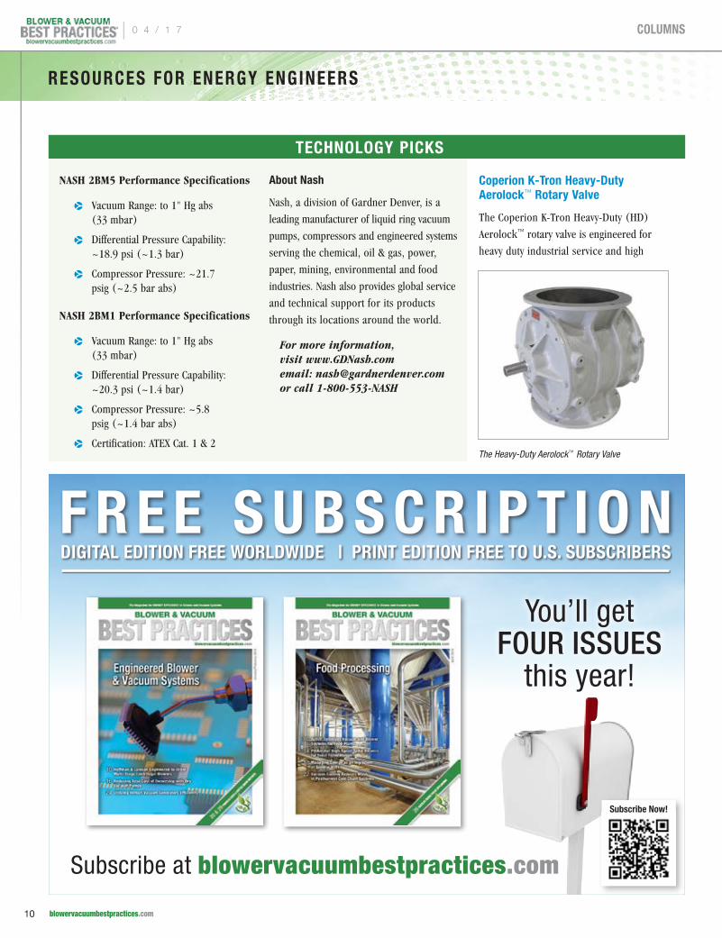
The Heavy-Duty Aerolock™ Rotary Valve
| 0 4 / 1 7
10 blowervacuumbestpractices.com
COLUMNS
volumetric efficiency at up to 1.0 bar [15
PSI] pressure differential. The HD conveys
a broad range of products in the plastics,
chemicals, minerals and food industries.
The HD Aerolock is used to handle pellets
and granular products, and will meter
powder materials at over 100,000 lbs./hr.
The Heavy-Duty Aerolock rotary valve
has an eight-blade rotor that maintains
a minimum two-blade labyrinth seal to
minimize air leakage. It is available with
relieved tips to prevent material buildup
on the housing or non-relieved tips for
other larger-particulate products.
About Coperion and Coperion K-Tron
Coperion K-Tron is a business unit of
Coperion and is a global leader and single
source supplier of material handling and
feeding systems. Coperion K-Tron has defined
the leading edge of technology for material
handling and feeding applications in the
process industries.
Coperion is the international market and
technology leader in compounding systems,
feeding technology, bulk materials handling
systems and services. Coperion designs,
develops, manufactures and maintains
systems, machines and components for
the plastics, chemicals, pharmaceutical,
food and minerals industries. Within
its four divisions – Compounding &
Extrusion, Equipment & Systems, Material
Handling and Service – Coperion has 2,500
employees and nearly 40 sales and service
companies worldwide.
For additional information visit www.coperionktron.com or email [email protected].
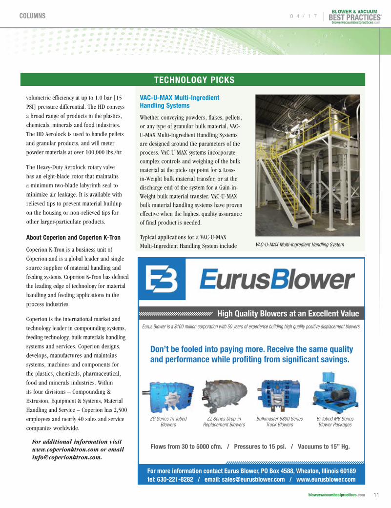
VAC-U-MAX Multi-Ingredient Handling Systems
Whether conveying powders, flakes, pellets, or any type of granular bulk material, VAC-U-MAX Multi-Ingredient Handling Systems are designed around the parameters of the process. VAC-U-MAX systems incorporate complex controls and weighing of the bulk material at the pick- up point for a Loss-in-Weight bulk material transfer, or at the discharge end of the system for a Gain-in-Weight bulk material transfer. VAC-U-MAX bulk material handling systems have proven effective when the highest quality assurance of final product is needed.
Typical applications for a VAC-U-MAX Multi-Ingredient Handling System include
ZG Series Tri-lobed Blowers
Bulkmaster 6800 Series Truck Blowers
ZZ Series Drop-in Replacement Blowers
Bi-lobed MB Series Blower Packages
High Quality Blowers at an Excellent Value Eurus Blower is a $100 million corporation with 50 years of experience building high quality positive displacement blowers.
Don’t be fooled into paying more. Receive the same quality and performance while profiting from significant savings.
For more information contact Eurus Blower, PO Box 4588, Wheaton, Illinois 60189 tel: 630-221-8282 / email: [email protected] / www.eurusblower.com
Flows from 30 to 5000 cfm. / Pressures to 15 psi. / Vacuums to 15” Hg.
VAC-U-MAX Multi-Ingredient Handling System
TECHNOLOGY PICKS
0 4 / 1 7 |
11 blowervacuumbestpractices.com
COLUMNS
RESOURCES FOR ENERGY ENGINEERS
pneumatically conveying bulk materials from-
and-to the following:
pp Storage bins to customers process
pp Storage vessels to weigh-hopper, and once the material is weighed the batch is transferred to the process
pp From several pick-up points to one batch-weigh receiver
pp Transferring bulk material to process via a VAC-U-MAX batch-weigh hopper
pp From bulk bag unloader to vacuum receiver incorporating flex-tube diverter valve
pp From bulk bag unloader to multiple vacuum receivers incorporating filter separator
pp Delivering bulk materials to two batch-weigh vacuum receivers
VAC-U-MAX systems combine modern
computerized technology with innovative
pneumatic and mechanical conveying,
for automated dust-free ingredient handling
with little or no human interface. Batch-
weigh system accuracies are within 0.5% of
the batch size, allowing for greater control of
end-product quality and inventory control of
bulk ingredients to the process. VAC-U-MAX is
a UL-listed designer and fabricator of control
panels for general purpose and hazardous
locations, with control systems configured to
a wide range of batch-weighing applications.
For more information visit www.vac-u-max.com.
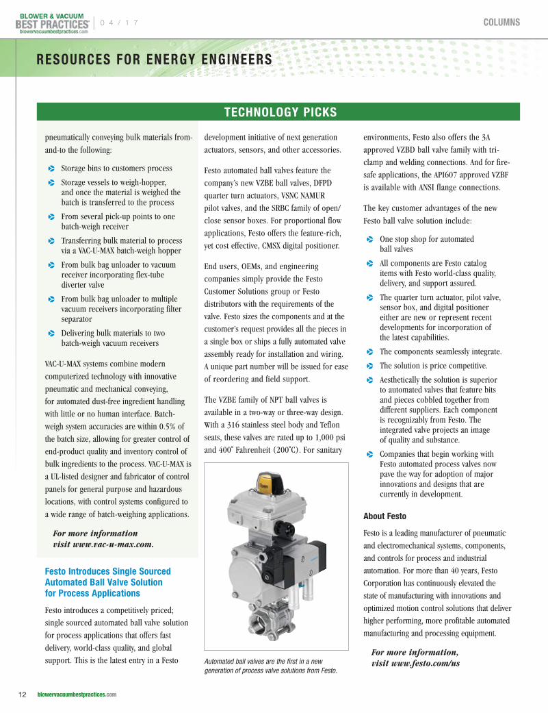
Festo Introduces Single Sourced Automated Ball Valve Solution for Process Applications
Festo introduces a competitively priced;
single sourced automated ball valve solution
for process applications that offers fast
delivery, world-class quality, and global
support. This is the latest entry in a Festo
development initiative of next generation
actuators, sensors, and other accessories.
Festo automated ball valves feature the
company’s new VZBE ball valves, DFPD
quarter turn actuators, VSNC NAMUR
pilot valves, and the SRBC family of open/
close sensor boxes. For proportional flow
applications, Festo offers the feature-rich,
yet cost effective, CMSX digital positioner.
End users, OEMs, and engineering
companies simply provide the Festo
Customer Solutions group or Festo
distributors with the requirements of the
valve. Festo sizes the components and at the
customer’s request provides all the pieces in
a single box or ships a fully automated valve
assembly ready for installation and wiring.
A unique part number will be issued for ease
of reordering and field support.
The VZBE family of NPT ball valves is
available in a two-way or three-way design.
With a 316 stainless steel body and Teflon
seats, these valves are rated up to 1,000 psi
and 400˚ Fahrenheit (200˚C). For sanitary
environments, Festo also offers the 3A
approved VZBD ball valve family with tri-
clamp and welding connections. And for fire-
safe applications, the API607 approved VZBF
is available with ANSI flange connections.
The key customer advantages of the new
Festo ball valve solution include:
pp One stop shop for automated ball valves
pp All components are Festo catalog items with Festo world-class quality, delivery, and support assured.
pp The quarter turn actuator, pilot valve, sensor box, and digital positioner either are new or represent recent developments for incorporation of the latest capabilities.
pp The components seamlessly integrate.
pp The solution is price competitive.
pp Aesthetically the solution is superior to automated valves that feature bits and pieces cobbled together from different suppliers. Each component is recognizably from Festo. The integrated valve projects an image of quality and substance.
pp Companies that begin working with Festo automated process valves now pave the way for adoption of major innovations and designs that are currently in development.
About Festo
Festo is a leading manufacturer of pneumatic
and electromechanical systems, components,
and controls for process and industrial
automation. For more than 40 years, Festo
Corporation has continuously elevated the
state of manufacturing with innovations and
optimized motion control solutions that deliver
higher performing, more profitable automated
manufacturing and processing equipment.
For more information, visit www.festo.com/us
TECHNOLOGY PICKS
Automated ball valves are the first in a new generation of process valve solutions from Festo.
| 0 4 / 1 7
12 blowervacuumbestpractices.com
COLUMNS
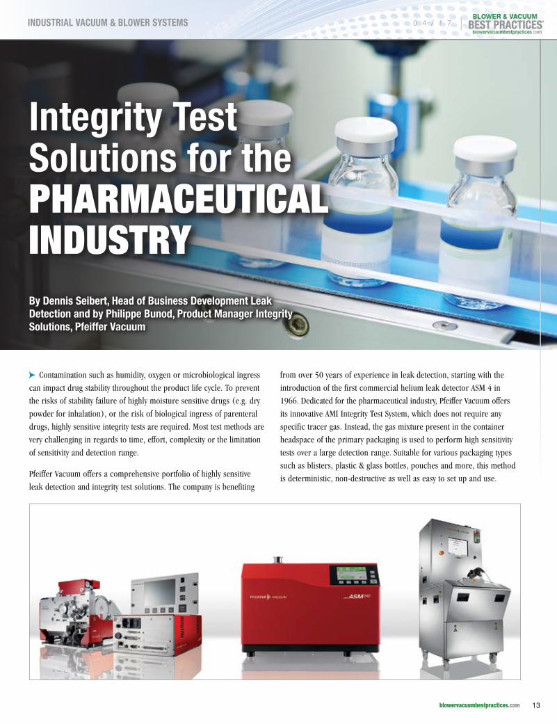
Integrity Test Solutions for the PHARMACEUTICAL INDUSTRYBy Dennis Seibert, Head of Business Development Leak Detection and by Philippe Bunod, Product Manager Integrity Solutions, Pfeiffer Vacuum
cpContamination such as humidity, oxygen or microbiological ingress
can impact drug stability throughout the product life cycle. To prevent
the risks of stability failure of highly moisture sensitive drugs (e.g. dry
powder for inhalation), or the risk of biological ingress of parenteral
drugs, highly sensitive integrity tests are required. Most test methods are
very challenging in regards to time, effort, complexity or the limitation
of sensitivity and detection range.
Pfeiffer Vacuum offers a comprehensive portfolio of highly sensitive
leak detection and integrity test solutions. The company is benefiting
from over 50 years of experience in leak detection, starting with the
introduction of the first commercial helium leak detector ASM 4 in
1966. Dedicated for the pharmaceutical industry, Pfeiffer Vacuum offers
its innovative AMI Integrity Test System, which does not require any
specific tracer gas. Instead, the gas mixture present in the container
headspace of the primary packaging is used to perform high sensitivity
tests over a large detection range. Suitable for various packaging types
such as blisters, plastic & glass bottles, pouches and more, this method
is deterministic, non-destructive as well as easy to set up and use.
0 4 / 1 7 |
13 blowervacuumbestpractices.com
INDUSTRIAL VACUUM & BLOWER SYSTEMS
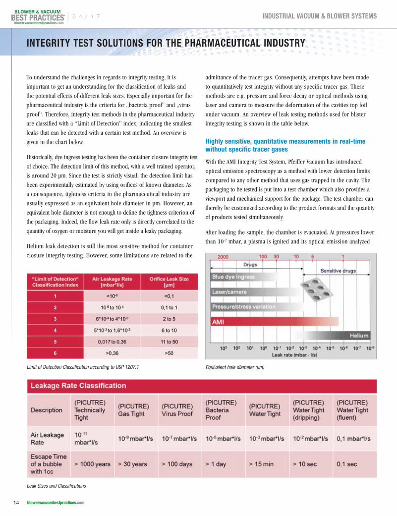
To understand the challenges in regards to integrity testing, it is
important to get an understanding for the classification of leaks and
the potential effects of different leak sizes. Especially important for the
pharmaceutical industry is the criteria for „bacteria proof“ and „virus
proof“. Therefore, integrity test methods in the pharmaceutical industry
are classified with a “Limit of Detection” index, indicating the smallest
leaks that can be detected with a certain test method. An overview is
given in the chart below.
Historically, dye ingress testing has been the container closure integrity test
of choice. The detection limit of this method, with a well trained operator,
is around 20 μm. Since the test is strictly visual, the detection limit has
been experimentally estimated by using orifices of known diameter. As
a consequence, tightness criteria in the pharmaceutical industry are
usually expressed as an equivalent hole diameter in μm. However, an
equivalent hole diameter is not enough to define the tightness criterion of
the packaging. Indeed, the flow leak rate only is directly correlated to the
quantity of oxygen or moisture you will get inside a leaky packaging.
Helium leak detection is still the most sensitive method for container
closure integrity testing. However, some limitations are related to the
admittance of the tracer gas. Consequently, attempts have been made
to quantitatively test integrity without any specific tracer gas. These
methods are e.g. pressure and force decay or optical methods using
laser and camera to measure the deformation of the cavities top foil
under vacuum. An overview of leak testing methods used for blister
integrity testing is shown in the table below.
Highly sensitive, quantitative measurements in real-time without specific tracer gases
With the AMI Integrity Test System, Pfeiffer Vacuum has introduced
optical emission spectroscopy as a method with lower detection limits
compared to any other method that uses gas trapped in the cavity. The
packaging to be tested is put into a test chamber which also provides a
viewport and mechanical support for the package. The test chamber can
thereby be customized according to the product formats and the quantity
of products tested simultaneously.
After loading the sample, the chamber is evacuated. At pressures lower
than 10-2 mbar, a plasma is ignited and its optical emission analyzed
Leak Sizes and Classifications
Limit of Detection Classification according to USP 1207.1 Equivalent hole diameter (µm)
INTEGRITY TEST SOLUTIONS FOR THE PHARMACEUTICAL INDUSTRY
| 0 4 / 1 7
14 blowervacuumbestpractices.com
INDUSTRIAL VACUUM & BLOWER SYSTEMS
with an optical emission spectrometer. The lowest detectable signal
corresponds to an orifice diameter of roughly 0.1 μm (according USP
<1207.1>). For further coarse leak tests the AMI sensor technology can
be complemented with a second dedicated leak sensor integrated into the
same test equipment to extend the upper detection limit up to few mm
holes. This gives the AMI the broadest detection range in the market.
The software solutions used in the AMI are compliant with 21 CFR
part 11. Optional software solutions are available for a manufacturing
execution system. Trend analysis can be implemented in the software
for early indication of drift production and packaging equipment.
This deterministic method is easy to set up and to use and yields
quantitative as well as highly repeatable results. In addition to the
information achieved by a simple GO/NOGO test method, the new
method of the AMI allows the detection of drifts in sealing parameters
in real time. The loss of valuable pharmaceuticals is prevented and
production stops for corrective measures are minimized.
The cycle time depends on the desired detection limit. For a leakage
rate of 1.0 · 10-4 mbar·l/s (about 1 μm according <USP 1207.1>),
a cycle time of 30 seconds can be expected. Automatic calibration is
implemented into the test equipment using certified calibrated leaks.
Thereby, operator-independent calibration and test results are provided.
Packaging Types and detection ranges
The AMI can be used for different types of packaging and sealed objects
like medical devices and battery cases. Thereby different sample sizes
and detection limits are applicable. In regards to blister packages
for example, the AMI can detect holes up to 0.4 μm respectively 2·10-5
mbar l/s (according to <USP 1207.1>). Thereby multiple blisters can
be tested simultaneously. About the same detection limit is provided
for plastic bottles. Here up to 100 bottles can be tested at the same
time. For glass vials the detection limit goes down to even 1/10 μm
hole or 1·10-6 mbar l/s leak rate (according to <USP 1207.1>). Also,
no sample preparation or storage time is required and the test results
will show within about 1 minute.
For more information on Pfeiffer Vacuum please visit www.pfeiffer-vacuum.com
INTEGRITY TEST SOLUTIONS FOR THE PHARMACEUTICAL INDUSTRY
To read more about Laboratory Applications, please visit www.blowervacuumbestpractices.com/industries/medical
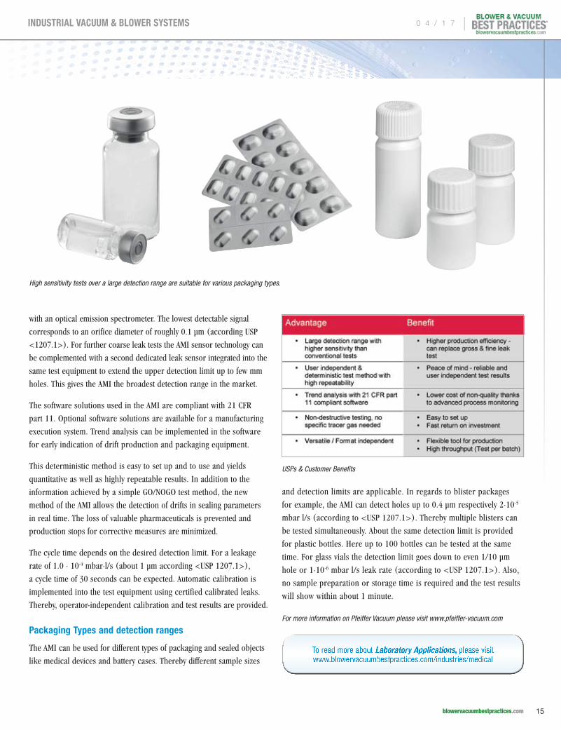
High sensitivity tests over a large detection range are suitable for various packaging types.
USPs & Customer Benefits
0 4 / 1 7 |
15 blowervacuumbestpractices.com
INDUSTRIAL VACUUM & BLOWER SYSTEMS

The Heart of Pneumatic Conveying Systems –
POSITIVE DISPLACEMENT BLOWER CALCULATIONS
By Roger E. Blanton, P.E., Sales Manager, Howden Roots
cpPneumatic conveying systems are widely
used in manufacturing plants and process
industries. They provide a practical method of
bulk-solid material transport. A surprisingly
wide variety of powders and granular material
can be effectively moved from one location
to another within the plant. “Compared with
other bulk-solid transport systems, a properly
designed pneumatic conveying system affords
many advantages, including: flexible pipeline
routing, multiple pick-up points (as in vacuum
systems), and delivery points (as in pressure
systems), little to no cross-contamination, dust
free operation, and an inert atmosphere.”1
The heart of the pneumatic conveying system (air
mover, solids feeder, pipeline, and separator) is
the air mover. Correctly specifying the volumetric
flow rate and pressure levels required to move
the material will determine system reliability. One
must also look at pipe size, distance, and the
weight of the material being moved. A company
“Selecting the correct blower is the most important decision when designing a pneumatic conveying system.”
— Roger E. Blanton, P.E., Sales Manager, Howden Roots
| 0 4 / 1 7
16 blowervacuumbestpractices.com
INDUSTRIAL VACUUM & BLOWER SYSTEMS
specializing in the design requirements of
pneumatic conveying systems is best consulted
for evaluating these requirements and specifying
the required air or gas flow rate for the system.
Using a high-pressure source, such as plant
compressed air, wastes valuable energy.
Howden Roots positive displacement (PD)
blowers provide a cost effective, efficient
solution. They are used extensively in dilute
phase applications where the bulk material is
conveyed through the pipeline in suspension,
and the required pressure does not exceed
15 PSIG. Not all, but several Howden Roots
blowers are bi-rotational so they can be used
for vacuum or pressure service.
The operating principle of a conventional
Roots type blower is quite simple. The reader
is directed to previous articles where this is
explained in detail, and not repeated here.2,3
It’s important to note that Roots blowers do
not create internal pressure or vacuum, they
simply overcome system losses.
PD Blower System Design and Capacity Control
Selecting the correct blower is the most
important decision when designing a
pneumatic conveying system. The rating
of the blower is expressed in terms of
required pressure and volumetric flow. Any
miscalculation in specifying the above will
result in a conveying system that is oversized,
isn’t capable of achieving the material flow rate
required, or experiences pipeline blockage.
Blockage occurs where the dynamic air or
gas pressure in the system is at its minimum
value. The volumetric flow rate from the
blower depends on the diameter of the pipe
being used and the velocity required to convey
the specified material. For design purposes,
standard conditions (68˚F, 14.7 psia, 36% RH,
0.075 lbs.ft3)4 are typically used in specifying
the blower.
Capacity control of PD blowers is limited
because the blower is cooled by the mass flow
through the machine. Throttling the blower
will result in overheating. Effective methods of
capacity control include,
pp Staging blowers off or on in systems where multiple blowers are used in parallel to attain required flow
pp Using a Variable Frequency Drive (VFD) on the blower motor to adjust blower speed within defined limits
pp Using a Blow Off Valve (BOV) in the blower discharge piping
pp Changing the sheave sizes on belt driven blowers.
PD Blower Limitations
Inherent by their design, a PD blower has both
mechanical and thermal limitations because
the impellers are machined to close tolerances
and the clearances are very small. Therefore,
PD blowers have speed, temperature and
pressure limitations that must be considered
when sizing a pneumatic conveying system. As
a general rule, PD blowers have the capability
to turndown to roughly 50% of the maximum
design speed because temperature rise
increases as unit speed decreases, as discussed
above. In addition, gear tip speed must be
maintained at a minimum of 1,000 FPM and a
maximum of approximately 4,700 FPM (varies
by model) – which is critical for proper
lubrication. Blowers are generally limited
to a maximum average temperature rise of
250˚F (121˚C) because of issues with thermal
growth. Lastly, Roots blowers are limited to
a 2:1 compression ratio because as pressure
increases there is a corresponding increase in
discharge temperature.
Basic Pneumatic Conveying System Calculations
Blower manufacturers do not routinely size
pneumatic conveying systems, leaving that task
to specialized design companies. However, it
is helpful to have some basic understanding
of the procedure. Preliminary design of
power, air requirements, and pipe size can
be developed, but experienced designers add
their own unique guidelines compatible with
their equipment. The material to be conveyed
and the distance required to move the material
limit pneumatic conveying systems.
Saturation (S) is defined as the cubic feet of
air required to move or convey one pound
of a given material for a specified distance.
Tables of this value (S), pressure factor (PF),
pipe velocity (v), and the horsepower required
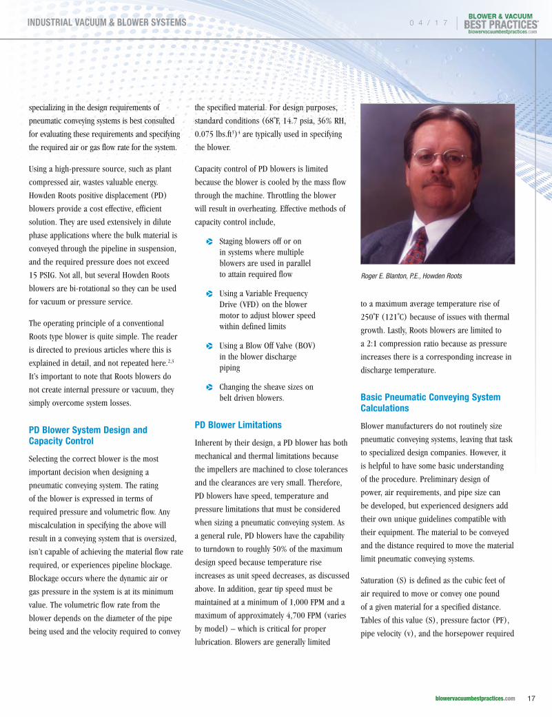
Roger E. Blanton, P.E., Howden Roots
0 4 / 1 7 |
17 blowervacuumbestpractices.com
INDUSTRIAL VACUUM & BLOWER SYSTEMS
THE HEART OF PNEUMATIC CONVEYING SYSTEMS – POSITIVE DISPLACEMENT BLOWER CALCULATIONS
to convey one ton of material per hour (HP)
have been published.5 Once the desired
total flow rate of the product and distance
involved is determined, and the material is
defined, a simple procedure can be followed
to preliminarily size the pneumatic conveying
system components.5
A Sample Calculation Sequence (for illustrative purposes only)5
1. Determine the Saturation (S), hp/ton (HP), pipe velocity (v), and Pressure Factor (PF) values for the conveyed product from the published saturation table.
2. Calculate the volume of free air (Qs) required
Qs (scfm) = S x conveying rate (lb/min)
3. Calculate the required operating pressure (P, psig)
P = HP/S x PF
4. Calculate the actual cubic feet per minute (acfm) at the feed point (site elevation = 0 feet asl)
acfm = scfm x 14.7 / (14.7 + P)
5. Calculate required pipe area (A)
A = acfm / v
6. Calculate rotary feeder leakage (L) in acfm
L = feeder volumetric displacement x feeder rpm x 1.3
7. Calculate feeder leakage in scfm (Ls)
Ls = L x (14.7 + P) / 14.7
Howden Roots PD Blowers for Pneumatic Conveying
Howden Roots has several blower models suitable for pneumatic conveying applications.
A few are shown in the following pictures and descriptions.
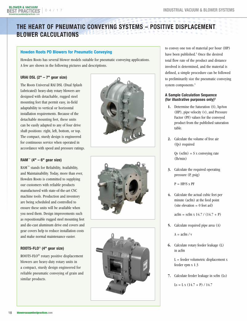
URAI DSL (2" – 7" gear size)
The Roots Universal RAI DSL (Dual Splash
Lubricated) heavy-duty rotary blowers are
designed with detachable, rugged steel
mounting feet that permit easy, in-field
adaptability to vertical or horizontal
installation requirements. Because of the
detachable mounting feet, these units
can be easily adapted to any of four drive
shaft positions: right, left, bottom, or top.
The compact, sturdy design is engineered
for continuous service when operated in
accordance with speed and pressure ratings.
RAM™ (4" – 6" gear size)
RAM™ stands for Reliability, Availability,
and Maintainability. Today, more than ever,
Howden Roots is committed to supplying
our customers with reliable products
manufactured with state-of-the-art CNC
machine tools. Production and inventory
are being scheduled and controlled to
ensure these units will be available when
you need them. Design improvements such
as repositionable rugged steel mounting feet
and die-cast aluminum drive end covers and
gear covers help to reduce installation costs
and make normal maintenance easier.
ROOTS-FLO® (4" gear size)
ROOTS-FLO® rotary positive displacement
blowers are heavy-duty rotary units in
a compact, sturdy design engineered for
reliable pneumatic conveying of grain and
similar products.
| 0 4 / 1 7
18 blowervacuumbestpractices.com
INDUSTRIAL VACUUM & BLOWER SYSTEMS
THE HEART OF PNEUMATIC CONVEYING SYSTEMS – POSITIVE DISPLACEMENT BLOWER CALCULATIONS
8. Calculate total air required by the blower (Q)
Q = Qs + Ls
9. Calculate required blower speed (Sb), rpm
Sb = Qs / blower displacement (cubic feet per revolution, cfr) + slip (rpm) [cfr & slip from blower manufacturer]
10. Calculate required blower horsepower (HP)
HP = Sb x cfr x P x 0.005
For more information please contact Roger Blanton, P.E., Howden Roots, at email:[email protected] or visit www.howdenroots.com
About the Author: Roger E. Blanton, P.E. is currently a Sales Manager for Howden Roots LLC based in Tulsa, Oklahoma USA. He is a registered professional engineer working for over 35 years with rotating equipment and petrochemical processes. Blanton holds a BS degree in Mechanical Engineering from the University of Tulsa, and an MBA degree from Oklahoma State University. He has specialized for the last 25 years in technical product design, application, and sales; new product development and introduction; sales and distribution management; and international business development. He is a member of the American Society of Mechanical Engineers (ASME), Tau Beta Pi Engineering Honor Society, and past president of the Greater Ozarks International Trade Association.
END NOTES
1. Maynard, Eric, “Designing Pneumatic Conveying Systems”, CEP Magazine, May 2006, pg. 23-31.
2. Blanton, Roger E., “Maintenance & Operation Guidelines for Rotary Lobe Blowers in Petrochemical Applications”, Presented at the 50th Annual Chem Show Conference, November 20, 2003, Javits Convention Center, New York City, NY. (copy available from author upon request)
3. Blanton, Roger E., “Get the Most Out of Your Rotary Lobe Blower”, Chemical Engineering, vol. 109 no. 7, July 2002, pg. 77-80.
4. “SCFM vs ACFM Are you really getting the blower performance you’re specifying?”, Dresser Industries, Inc. Roots Division, 1988, Houston, TX.
5. Stoess, H.A. Jr., Pneumatic Conveying, John Wiley & Sons, 1970.
To read similar articles on Pneumatic Conveying, please visit
www.blowervacuumbestpractices.com/industries/conveying
FREE SUBSCRIPTIOND I G I T A L E D I T I O N F R E E W O R L D W I D E PRINT EDITION FREE TO U.S. SUBSCRIBERS
You’ll get FOUR ISSUES of each supplement this year!
Subscribe at coolingbestpractices.com or blowervacuumbestpractices.com
p Cooling Towers
p Central Plant Chillers
p Cooling System Components
EVERY ISSUE CONTAINS BEST PRACTICES FOR:
p Industrial Vacuum
p Vacuum Generation
p Industrial & Aeration Blowers
p Blow-Off Air
EVERY ISSUE CONTAINS BEST PRACTICES FOR:
Subscribe Now!
Subscribe Now!
0 4 / 1 7 |
19 blowervacuumbestpractices.com
INDUSTRIAL VACUUM & BLOWER SYSTEMS

Vacuum System Fundamentals for“ COMPRESSED AIR PEOPLE”By Tim Dugan, P.E., President, Compression Engineering Corporation
cpIntroduction
Based on my 28 years’ experience, I am an
unapologetic “compressed air nerd”. But, I
also understand vacuum systems. The reason
I do is that I look at every problem from the
fundamentals, not from rules of thumb. Any
technical field develops a language and a set
of “rules of thumb”. It is helpful to do this, to
disseminate ideas and practices broadly and
quickly. These ways of thinking get reinforced
when they appear to “work”. However, this
type of thinking tends to create pathways of
thinking that are ruts. These ruts run deep
in every field, particularly compressed air.
If you want to understand vacuum systems, you
have to get out of the ruts, and slog through
the mud and bounce over the rocks a bit.
If you’re a “compressed air person”, think
outside the box for a few pages with me. I am
going to borrow some terms from the “pump
people” to explain how vacuum systems are
similar, yet different from compressed air
systems. There are several ruts to get out of.
Remembering what changes and what doesn’t,
what is controlled, and how to design systems
for optimal energy consumption.
“If you want to understand vacuum systems, you have to get out of the ruts, and slog through the mud and bounce over the rocks a bit.”
— Tim Dugan, P.E., President, Compression Engineering Corporation
| 0 4 / 1 7
20 blowervacuumbestpractices.com
INDUSTRIAL VACUUM & BLOWER SYSTEMS
What Changes and What Doesn’t: System Resistance Changes
Always start with the system. Pump people
teach us to look at a system as an “equivalent
orifice”, a resistance that flow and pressure
are related to one another, and to develop a
“system resistance curve” first. Both vacuum
and compressed air systems are essentially a
variable leak, a variable hole, with air moving
from one pressure to another across it. This
seems to be analogous to a variable flow
demand. But be careful. The system is really
just holes that open and close, or have variable
sized holes (control valves). In some limited
cases, flow control is part of the system,
making it actually a flow-based demand. But
that is uncommon. The aggregate of all these
variable holes is the “system”. The system
gulps what it wants, independent of the vacuum
pumps or compressors attempting to serve it.
For vacuum systems, air moves from constant
ambient pressure to the vacuum pump inlet
pressure. For compressed air system, it moves
from the compressor’s roughly constant
discharge pressure to ambient pressure.
In both cases, the system typically acts as
a “choked orifice”. Air is trying to move
through the orifice too fast, and is limited
based on a maximum pressure ratio of about
53% for air. Basically, a shock wave exists
at the point that air is trying to get into the
system. For a choked orifice, mass flow is
proportional to the inlet pressure. In layman’s
terms, this means that if you double either
the inlet pressure to the system, you get
about double the flow – assuming that you
can deliver it. In a vacuum system, you can’t
change the “inlet pressure” to the system –
it’s ambient pressure. But that’s just theory.
You have to be able to magically increase or
decrease mass flow to respond to that need
to change pressure, and real vacuum pumps
can’t do that without a VFD. Or you have to
operate at widely ranging pressures, which
compressors don’t do. More on that below.
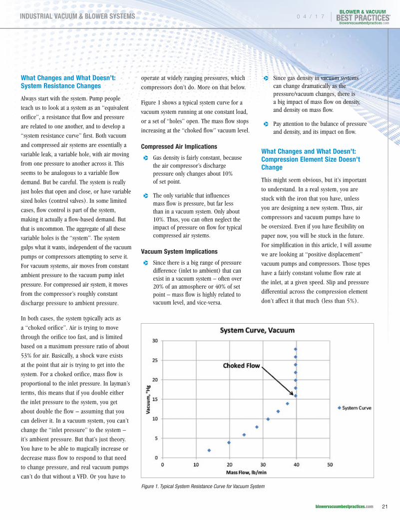
Figure 1 shows a typical system curve for a
vacuum system running at one constant load,
or a set of “holes” open. The mass flow stops
increasing at the “choked flow” vacuum level.
Compressed Air Implications
pp Gas density is fairly constant, because the air compressor’s discharge pressure only changes about 10% of set point.
pp The only variable that influences mass flow is pressure, but far less than in a vacuum system. Only about 10%. Thus, you can often neglect the impact of pressure on flow for typical compressed air systems.
Vacuum System Implications
pp Since there is a big range of pressure difference (inlet to ambient) that can exist in a vacuum system – often over 20% of an atmosphere or 40% of set point – mass flow is highly related to vacuum level, and vice-versa.
pp Since gas density in vacuum systems can change dramatically as the pressure/vacuum changes, there is a big impact of mass flow on density, and density on mass flow.
pp Pay attention to the balance of pressure and density, and its impact on flow.
What Changes and What Doesn’t: Compression Element Size Doesn’t Change
This might seem obvious, but it’s important
to understand. In a real system, you are
stuck with the iron that you have, unless
you are designing a new system. Thus, air
compressors and vacuum pumps have to
be oversized. Even if you have flexibility on
paper now, you will be stuck in the future.
For simplification in this article, I will assume
we are looking at “positive displacement”
vacuum pumps and compressors. Those types
have a fairly constant volume flow rate at
the inlet, at a given speed. Slip and pressure
differential across the compression element
don’t affect it that much (less than 5%).
Figure 1. Typical System Resistance Curve for Vacuum System
0 4 / 1 7 |
21 blowervacuumbestpractices.com
INDUSTRIAL VACUUM & BLOWER SYSTEMS
VACUUM SYSTEM FUNDAMENTALS FOR “COMPRESSED AIR PEOPLE”
All you can do to make the most of a
system is to attempt to match the right air
compressor or vacuum pump to the right
system, which is difficult because you have
a widely varying “system resistance”. The
compressor or vacuum pump has to be
oversized for average demand, or the system
will crash at max demand.
Vacuum pumps and air compressors are sized
for inlet flow, at full speed and a particular
pressure ratio that is optimal. For instance,
1,000 “acfm” and 100 psig for a compressor.
That is 1,000 cubic feet per minute at the inlet,
independent of density, compressing from
ambient pressure to 100 psig. It just takes a
scoop of 1,000 ft3 volume every minute, and
squeezes it 7.8 times. Typically a curve is not
provided, just a full capacity data sheet. If
one is, it shows power versus flow, not flow
versus pressure. See Figure 1 for an example.
Pressure is magically relatively constant, so the
engineer doesn’t think about how it impacts on
the flow capacity of the compressor, or how it
balances against the system.
A 1,000 “icfm” vacuum pump could use
the same compression element as the 1,000
acfm compressor, or one modified with a
different compression ratio to optimize for
vacuum system operation, 1,000 icfm at
28"Hg for instance. It would have a much
smaller motor and a larger separator (if
lubricated). Its performance would look flat
as a pancake from 10"Hg to about 25"Hg,
and decline slightly after that. See Figure 2
for an example. But don’t be fooled. Your
real system will not require 1,000 icfm in all
vacuum ranges. Recall that the system is just
a hole. The vacuum pump will pull down until
it balances at whatever pressure differential/
density balances with the system resistance
at the time.
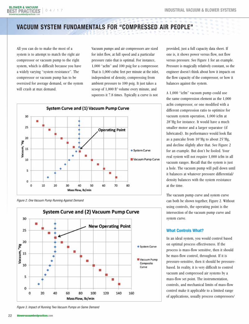
The vacuum pump curve and system curve
can both be shown together, Figure 2. Without
using controls, the operating point is the
intersection of the vacuum pump curve and
system curve.
What Controls What?
In an ideal system, you would control based
on optimal process effectiveness. If the
process is mass-flow sensitive, then it should
be mass-flow control, throughout. If it is
pressure-sensitive, then it should be pressure-
based. In reality, it is very difficult to control
vacuum and compressed air systems by a
mass-flow set point. The instrumentation,
controls, and mechanical limits of mass-flow
control make it applicable to a limited range
of applications, usually process compressors/
Figure 2. One Vacuum Pump Running Against Demand
Figure 3. Impact of Running Two Vacuum Pumps on Same Demand
| 0 4 / 1 7
22 blowervacuumbestpractices.com
INDUSTRIAL VACUUM & BLOWER SYSTEMS
VACUUM SYSTEM FUNDAMENTALS FOR “COMPRESSED AIR PEOPLE”
vacuum, and not general plant air vacuum.
For this article, we are discussing general
plant systems. These systems are pressure-
controlled in practice, whether the system
needs mass-flow controlled or pressure
controlled. But the system does what it
does all on its own, and is the “feedback
loop” that dominates the actual operation.
Compressed Air Implications
System demand is independent of pressure
within the air compressor’s operating range.
System demand = A, pressure = B, and flow
= C. Control happens A to B to C, essentially
A=>C. There is a small feedback between
pressure and system demand (C => A),
but not much. System demand changes
pressure, just a small amount up or down on
the “system curve”, the control system cuts
back or increases compressor flow to match
system flow – by stabilizing pressure. As an
example, an inlet modulating compressor
uses a proportional pilot valve to control
its inlet valve to a given plant pressure,
and a VFD control controls speed to maintain
a plant’s pressure.
Vacuum System Implications
System demand is dependent on pressure in
a vacuum pump’s operating range. Typically,
pumps are pulling too low of a vacuum, to
be safe, and that lower vacuum is causing
a false demand on the vacuum pump. Thus,
A =>B => C => A, and it reaches a balance.
Even if mass flow is choked, the lower
vacuum causes a higher vacuum pump inlet
flow (icfm) to hit that same mass flow, and
that takes more power. See Figure 3 for the
same system resistance as shown in Figure
1, but with two vacuum pumps running. The
system will just balance at a lower vacuum,
22"Hg versus 15"Hg. Power will be about
double, and the process wouldn’t even know
that the other vacuum pump was on. Unlike
a compressed air system that would over-
pressurize and cause a compressor to unload,
the vacuum pumps essentially “self-throttle”
against the system.
Design for Optimal Energy Consumption: Determine the Vacuum Level and Flow Actually Needed
Start at the process, the part that creates
the demand, the “holes”. There are multiple
types. Fixed and varying demand, pump-down
and hold, and constant flow. For instance,
in a CNC routing table’s “hole” is the sum of
airbestpractices.com
ENERGY KAIZEN EVENTS
Get your FREE Subscription to Compressed Air Best Practices® Magazine to learn how to save energy.
Subscribe at
p Food Packaging Plant Saves $70,000 or 1.1 Million kWh per year. p Paper Mill Saves $207,000 or 4.5 Million kWh per year.
Subscribe Now!
0 4 / 1 7 |
23 blowervacuumbestpractices.com
INDUSTRIAL VACUUM & BLOWER SYSTEMS
a bunch of tiny holes that pull air through
the table to hold a work piece down. It is
a varying demand because the flow only
occurs when the table is not covered, and
many different types of work pieces cover the
table, leaving a varying area uncovered. In
a chemical process, the “hole” is usually a
control valve maintaining a particular process
variable, and the flow is fairly constant. In a
robot application, the “hole” is the suction
cup that has a very small volume, and holds a
piece to block the hole, zero flow, then drops
it and has a high flow.
If you can perform an analysis of all the
demands, the best way is to turn them all into
equivalent orifices or CVs (a valve sizing term,
similar to hole size, but more technical).
Then, using the minimum required vacuum
level for the system (the lowest vacuum
needed for all), aggregate them and develop
a peak and average flow, using the orifice
flow formula, up to the choked flow level.
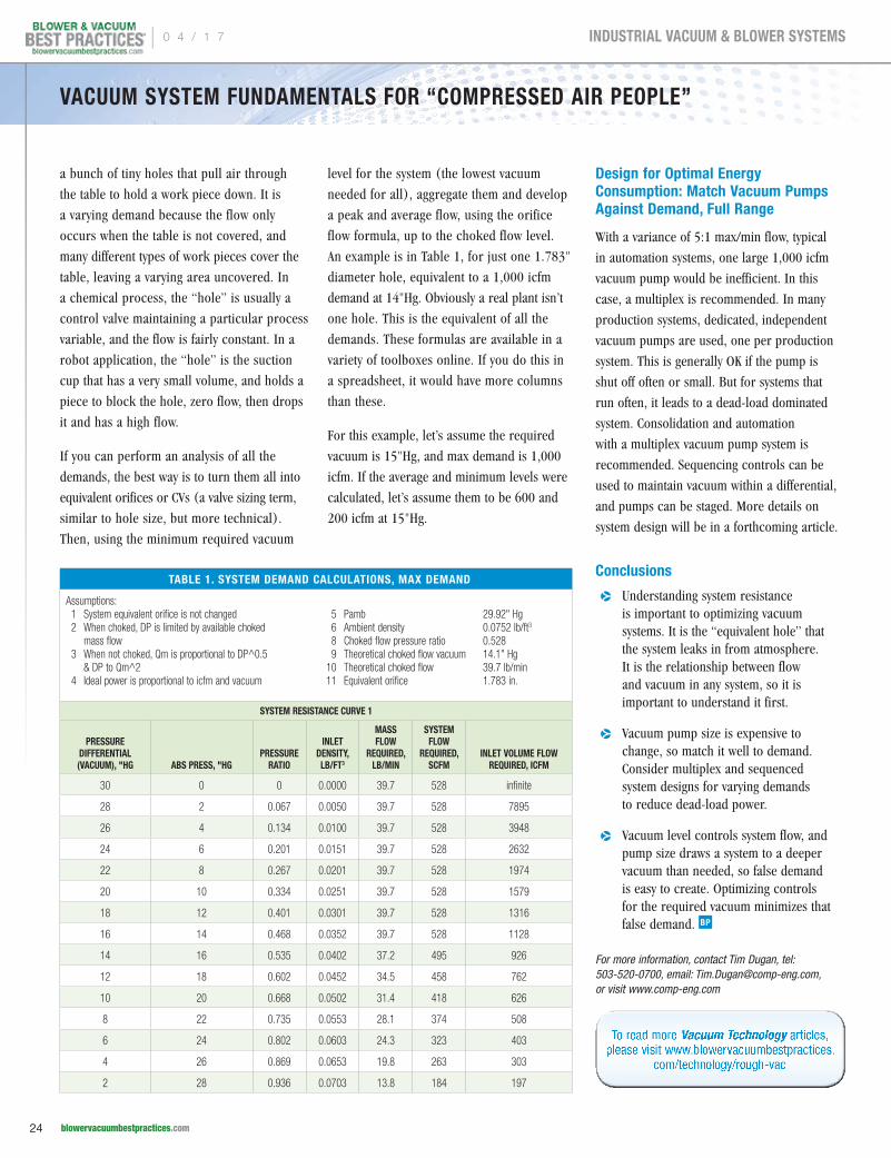
An example is in Table 1, for just one 1.783"
diameter hole, equivalent to a 1,000 icfm
demand at 14"Hg. Obviously a real plant isn’t
one hole. This is the equivalent of all the
demands. These formulas are available in a
variety of toolboxes online. If you do this in
a spreadsheet, it would have more columns
than these.
For this example, let’s assume the required
vacuum is 15"Hg, and max demand is 1,000
icfm. If the average and minimum levels were
calculated, let’s assume them to be 600 and
200 icfm at 15"Hg.
Design for Optimal Energy Consumption: Match Vacuum Pumps Against Demand, Full Range
With a variance of 5:1 max/min flow, typical
in automation systems, one large 1,000 icfm
vacuum pump would be inefficient. In this
case, a multiplex is recommended. In many
production systems, dedicated, independent
vacuum pumps are used, one per production
system. This is generally OK if the pump is
shut off often or small. But for systems that
run often, it leads to a dead-load dominated
system. Consolidation and automation
with a multiplex vacuum pump system is
recommended. Sequencing controls can be
used to maintain vacuum within a differential,
and pumps can be staged. More details on
system design will be in a forthcoming article.
Conclusions
pp Understanding system resistance is important to optimizing vacuum systems. It is the “equivalent hole” that the system leaks in from atmosphere. It is the relationship between flow and vacuum in any system, so it is important to understand it first.
pp Vacuum pump size is expensive to change, so match it well to demand. Consider multiplex and sequenced system designs for varying demands to reduce dead-load power.
pp Vacuum level controls system flow, and pump size draws a system to a deeper vacuum than needed, so false demand is easy to create. Optimizing controls for the required vacuum minimizes that false demand.
For more information, contact Tim Dugan, tel: 503-520-0700, email: [email protected], or visit www.comp-eng.com
To read more Vacuum Technology articles, please visit www.blowervacuumbestpractices.
com/technology/rough-vac
TABLE 1. SYSTEM DEMAND CALCULATIONS, MAX DEMAND
Assumptions: 1 System equivalent orifice is not changed 2 When choked, DP is limited by available choked
mass flow 3 When not choked, Qm is proportional to DP^0.5
& DP to Qm^2 4 Ideal power is proportional to icfm and vacuum
5 Pamb 29.92" Hg 6 Ambient density 0.0752 lb/ft3
8 Choked flow pressure ratio 0.528 9 Theoretical choked flow vacuum 14.1" Hg 10 Theoretical choked flow 39.7 lb/min 11 Equivalent orifice 1.783 in.
SYSTEM RESISTANCE CURVE 1
PRESSURE DIFFERENTIAL (VACUUM), "HG ABS PRESS, "HG
PRESSURE RATIO
INLET DENSITY, LB/FT3
MASS FLOW
REQUIRED, LB/MIN
SYSTEM FLOW
REQUIRED, SCFM
INLET VOLUME FLOW REQUIRED, ICFM
30 0 0 0.0000 39.7 528 infinite
28 2 0.067 0.0050 39.7 528 7895
26 4 0.134 0.0100 39.7 528 3948
24 6 0.201 0.0151 39.7 528 2632
22 8 0.267 0.0201 39.7 528 1974
20 10 0.334 0.0251 39.7 528 1579
18 12 0.401 0.0301 39.7 528 1316
16 14 0.468 0.0352 39.7 528 1128
14 16 0.535 0.0402 37.2 495 926
12 18 0.602 0.0452 34.5 458 762
10 20 0.668 0.0502 31.4 418 626
8 22 0.735 0.0553 28.1 374 508
6 24 0.802 0.0603 24.3 323 403
4 26 0.869 0.0653 19.8 263 303
2 28 0.936 0.0703 13.8 184 197
VACUUM SYSTEM FUNDAMENTALS FOR “COMPRESSED AIR PEOPLE”
| 0 4 / 1 7
24 blowervacuumbestpractices.com
INDUSTRIAL VACUUM & BLOWER SYSTEMS
Busch Provides ReliableOxygen Supply to Aeration Tanks
By Uli Merkle, Busch Vacuum Pumps and Systems
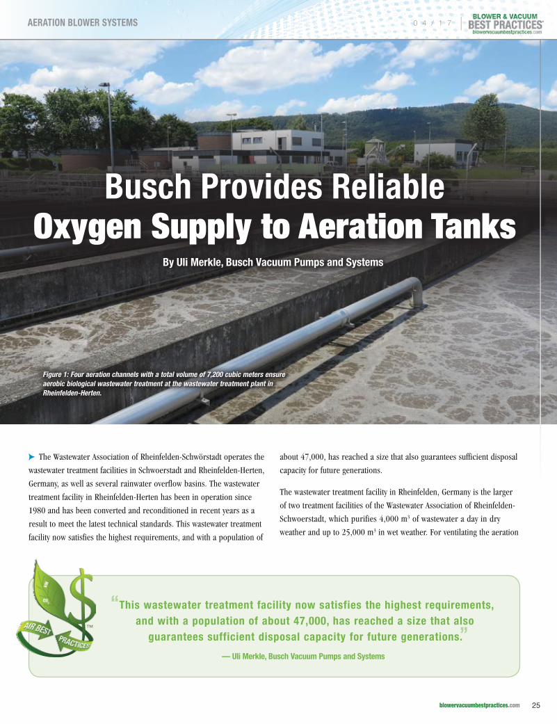
cpThe Wastewater Association of Rheinfelden-Schwörstadt operates the
wastewater treatment facilities in Schwoerstadt and Rheinfelden-Herten,
Germany, as well as several rainwater overflow basins. The wastewater
treatment facility in Rheinfelden-Herten has been in operation since
1980 and has been converted and reconditioned in recent years as a
result to meet the latest technical standards. This wastewater treatment
facility now satisfies the highest requirements, and with a population of
about 47,000, has reached a size that also guarantees sufficient disposal
capacity for future generations.
The wastewater treatment facility in Rheinfelden, Germany is the larger
of two treatment facilities of the Wastewater Association of Rheinfelden-
Schwoerstadt, which purifies 4,000 m3 of wastewater a day in dry
weather and up to 25,000 m3 in wet weather. For ventilating the aeration
Figure 1: Four aeration channels with a total volume of 7,200 cubic meters ensure aerobic biological wastewater treatment at the wastewater treatment plant in Rheinfelden-Herten.
“This wastewater treatment facility now satisfies the highest requirements, and with a population of about 47,000, has reached a size that also
guarantees sufficient disposal capacity for future generations.”— Uli Merkle, Busch Vacuum Pumps and Systems
0 4 / 1 7 |
25 blowervacuumbestpractices.com
AERATION BLOWER SYSTEMS
BUSCH PROVIDES RELIABLE OXYGEN SUPPLY TO AERATION TANKS
channels, the facility relies on Tyr rotary lobe blowers from Busch,
which provide the necessary injection of oxygen.
Thanks to a total investment of about $8.4 million in the latest
technologies, the Wastewater Association has reduced pollutants
further, which has a positive impact on the water quality of the natural
watercourses. The methane gas produced in the digestion tower is
used to power a gas engine in the facility’s own co-generation plant.
The generator driven by this produces an average of 105 kW/h. This
means that up to 50% of the energy required can be generated by the
facility itself. In addition to this, the facility’s own heating system runs
on sewage gas.
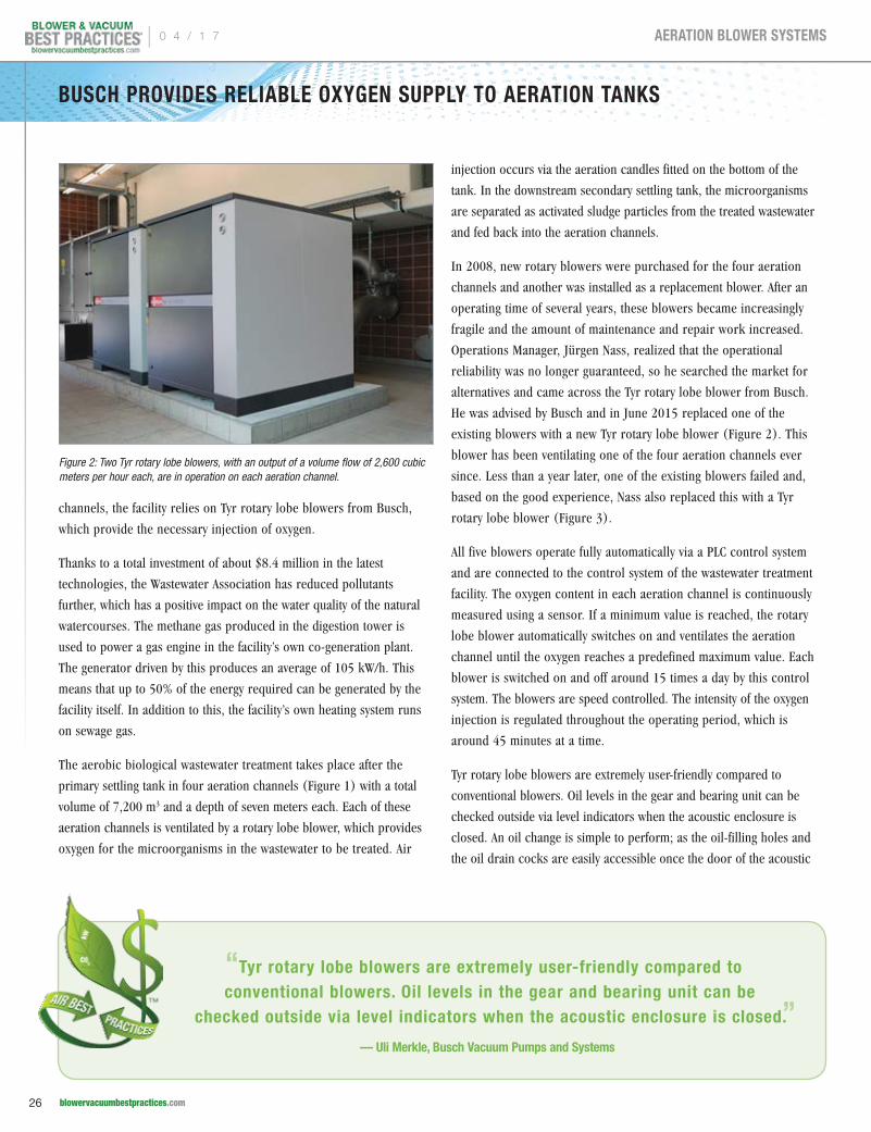
The aerobic biological wastewater treatment takes place after the
primary settling tank in four aeration channels (Figure 1) with a total
volume of 7,200 m3 and a depth of seven meters each. Each of these
aeration channels is ventilated by a rotary lobe blower, which provides
oxygen for the microorganisms in the wastewater to be treated. Air
injection occurs via the aeration candles fitted on the bottom of the
tank. In the downstream secondary settling tank, the microorganisms
are separated as activated sludge particles from the treated wastewater
and fed back into the aeration channels.
In 2008, new rotary blowers were purchased for the four aeration
channels and another was installed as a replacement blower. After an
operating time of several years, these blowers became increasingly
fragile and the amount of maintenance and repair work increased.
Operations Manager, Jürgen Nass, realized that the operational
reliability was no longer guaranteed, so he searched the market for
alternatives and came across the Tyr rotary lobe blower from Busch.
He was advised by Busch and in June 2015 replaced one of the
existing blowers with a new Tyr rotary lobe blower (Figure 2). This
blower has been ventilating one of the four aeration channels ever
since. Less than a year later, one of the existing blowers failed and,
based on the good experience, Nass also replaced this with a Tyr
rotary lobe blower (Figure 3).
All five blowers operate fully automatically via a PLC control system
and are connected to the control system of the wastewater treatment
facility. The oxygen content in each aeration channel is continuously
measured using a sensor. If a minimum value is reached, the rotary
lobe blower automatically switches on and ventilates the aeration
channel until the oxygen reaches a predefined maximum value. Each
blower is switched on and off around 15 times a day by this control
system. The blowers are speed controlled. The intensity of the oxygen
injection is regulated throughout the operating period, which is
around 45 minutes at a time.
Tyr rotary lobe blowers are extremely user-friendly compared to
conventional blowers. Oil levels in the gear and bearing unit can be
checked outside via level indicators when the acoustic enclosure is
closed. An oil change is simple to perform; as the oil-filling holes and
the oil drain cocks are easily accessible once the door of the acoustic
Figure 2: Two Tyr rotary lobe blowers, with an output of a volume flow of 2,600 cubic meters per hour each, are in operation on each aeration channel.
“Tyr rotary lobe blowers are extremely user-friendly compared to conventional blowers. Oil levels in the gear and bearing unit can be
checked outside via level indicators when the acoustic enclosure is closed.”— Uli Merkle, Busch Vacuum Pumps and Systems
| 0 4 / 1 7
26 blowervacuumbestpractices.com
AERATION BLOWER SYSTEMS
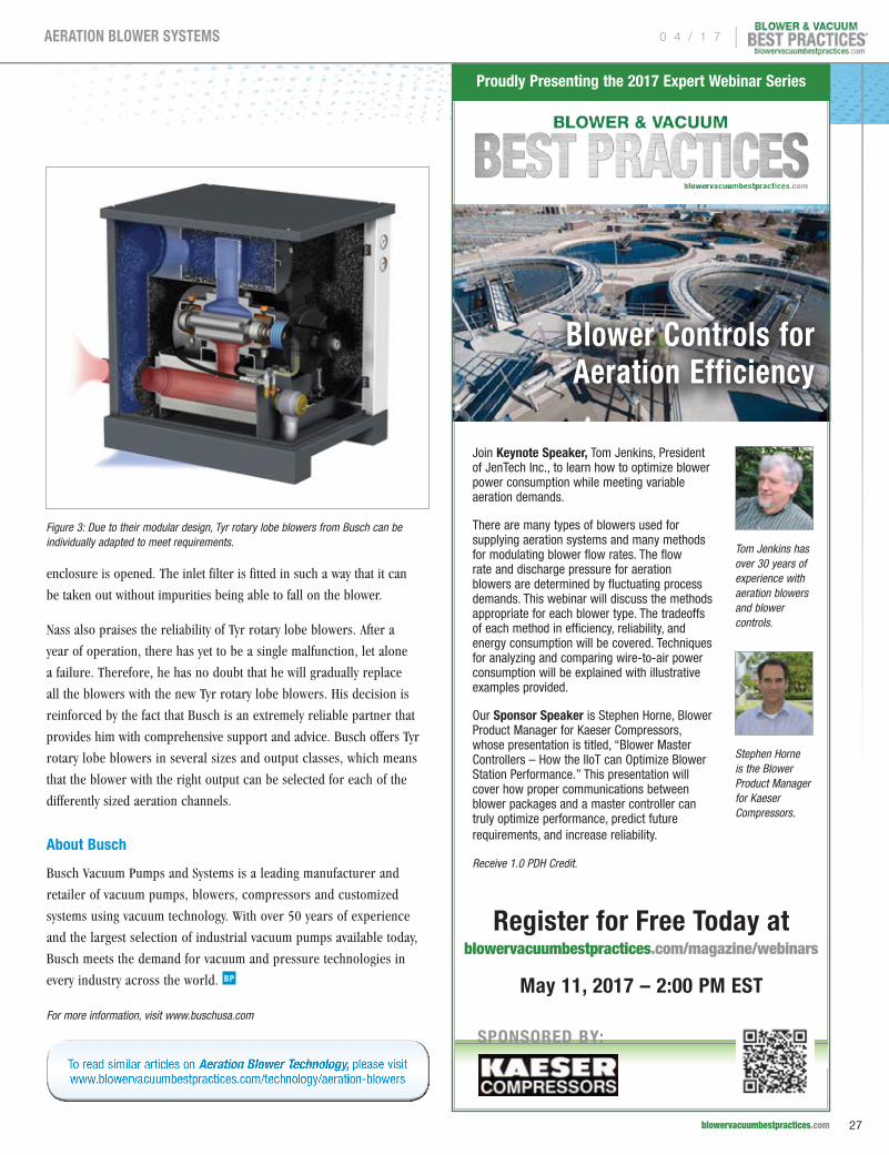
enclosure is opened. The inlet filter is fitted in such a way that it can
be taken out without impurities being able to fall on the blower.
Nass also praises the reliability of Tyr rotary lobe blowers. After a
year of operation, there has yet to be a single malfunction, let alone
a failure. Therefore, he has no doubt that he will gradually replace
all the blowers with the new Tyr rotary lobe blowers. His decision is
reinforced by the fact that Busch is an extremely reliable partner that
provides him with comprehensive support and advice. Busch offers Tyr
rotary lobe blowers in several sizes and output classes, which means
that the blower with the right output can be selected for each of the
differently sized aeration channels.
About Busch
Busch Vacuum Pumps and Systems is a leading manufacturer and
retailer of vacuum pumps, blowers, compressors and customized
systems using vacuum technology. With over 50 years of experience
and the largest selection of industrial vacuum pumps available today,
Busch meets the demand for vacuum and pressure technologies in
every industry across the world.
For more information, visit www.buschusa.com
Figure 3: Due to their modular design, Tyr rotary lobe blowers from Busch can be individually adapted to meet requirements.
To read similar articles on Aeration Blower Technology, please visit www.blowervacuumbestpractices.com/technology/aeration-blowers
Blower Controls for Aeration Efficiency
Join Keynote Speaker, Tom Jenkins, President of JenTech Inc., to learn how to optimize blower power consumption while meeting variable aeration demands.
There are many types of blowers used for supplying aeration systems and many methods for modulating blower flow rates. The flow rate and discharge pressure for aeration blowers are determined by fluctuating process demands. This webinar will discuss the methods appropriate for each blower type. The tradeoffs of each method in efficiency, reliability, and energy consumption will be covered. Techniques for analyzing and comparing wire-to-air power consumption will be explained with illustrative examples provided.
Our Sponsor Speaker is Stephen Horne, Blower Product Manager for Kaeser Compressors, whose presentation is titled, “Blower Master Controllers – How the IIoT can Optimize Blower Station Performance.” This presentation will cover how proper communications between blower packages and a master controller can truly optimize performance, predict future requirements, and increase reliability.
Receive 1.0 PDH Credit.
Register for Free Today at blowervacuumbestpractices.com/magazine/webinars
May 11, 2017 – 2:00 PM EST
Proudly Presenting the 2017 Expert Webinar Series
SPONSORED BY:
Tom Jenkins has over 30 years of experience with aeration blowers and blower controls.
Stephen Horne is the Blower Product Manager for Kaeser Compressors.
0 4 / 1 7 |
27 blowervacuumbestpractices.com
AERATION BLOWER SYSTEMS
BLOWER & VACUUM SYSTEM INDUSTRY NEWSTrinos Changes Name to Pfeiffer Vacuum Components & Solutions
As of early 2017, Trinos Vakuum-Systeme GmbH has a new name:
Pfeiffer Vacuum Components & Solutions GmbH. The company based in
Goettingen employs some 160 people and has been part of the Pfeiffer
Vacuum Group since January 2010. The name Pfeiffer Vacuum has stood
for high quality vacuum technology, a comprehensive range of products
and first-class service for more than 125 years. With its close customer
collaboration and consistent focus on customer needs, Pfeiffer Vacuum
is constantly optimizing and expanding its portfolio.
“The objective of the change in name is to further develop and
strengthen our market position. Our product portfolio in Goettingen
includes vacuum components, custom vacuum chambers, valves and
manipulators. We see ourselves as a premium supplier of vacuum
components and a specialist for customer-specific vacuum systems
with a wide range of functions,” explains Guido Hamacher, Managing
Director of Pfeiffer Vacuum Components & Solutions GmbH. “We’ve
planned expansive investments at our Goettingen site for 2017 so that
we can continue to remain competitive in the future and secure existing
jobs as well as create new ones.
We are looking into the future with optimism and expect more growth
in the coming months,” added Hamacher.
Vacuum technology makes it possible to produce solar cells,
semiconductors, thermal glass and coatings for extremely durable
mechanical tools. These are just a few examples of Pfeiffer Vacuum
products. Reliable vacuum products and systems are also of major
importance for research and development, analytics, environmental
technology and the automotive industry.
About Pfeiffer Vacuum
Pfeiffer Vacuum is one of the world’s leading providers of vacuum
solutions. In addition to a full range of hybrid and magnetically
levitated turbopumps, the product portfolio comprises backing pumps,
leak detectors, measurement and analysis devices, components, as
well as vacuum chambers and systems. Ever since the invention of the
turbopump by Pfeiffer Vacuum, the company has stood for innovative
solutions and high-tech products that are used in the Analytics,
Industry, Research & Development, Coating and Semiconductor
markets. Founded in 1890, Pfeiffer Vacuum is active throughout the
world today. The company employs a workforce of some 2,350 people
and has more than 20 subsidiaries.
For more information, please visit www.pfeiffer-vacuum.com.
Aerzen USA CFO & Vice President Keith Rolfe Wins SMARTCEO Award
Aerzen USA announced that Keith Rolfe, Vice President and CFO of Aerzen
USA Corp., was selected as a winner of a 2016 Executive Management
Award by Philadelphia SmartCEO. Rolfe was chosen because of his focus
on investing in people and supporting the company’s “triple bottom
line” approach to business, which encompasses People, The Planet
and Prosperity.
The honor reflects Rolfe’s contributions to Aerzen USA, having served
as the Company's Chief Financial Officer and recently, as Vice President.
Rolfe provides strategic leadership and know-how to the Aerzen
USA Management team. His efforts made him an ideal candidate for
Philadelphia SmartCEO's Executive Management Awards.
“Employees find our company unique to work for because we support
a “triple bottom line” approach to business by focusing on People,
The Planet and Prosperity,”
Rolfe explains. “Our people
are the most important asset
in the company and we invest
in them significantly, to ensure
high quality solutions for
our customers. The company
occupies a LEED Gold Certified
Green building and was a
pioneer in making this facility
come to life as one of the first
in Pennsylvania.
Pfeiffer Vacuum Components & Solutions GmbH, Goettingen
Aerzen USA CFO & Vice President Keith Rolfe
| 0 4 / 1 7
28 blowervacuumbestpractices.com
COLUMNS
Energy savings, monitoring and reducing waste streams, and producing
highly efficient products underpins the company’s commitment to being
a good steward of the environment and our community. We are active
with our community by giving back either financially or in the form of
food donations from our gardens and providing our facility for trainings
and meetings to groups and organizations, so that they can be part of
the growing community.”
The Executive Management Awards program recognizes the leadership
and accomplishments of Philadelphia's management all-stars — the
CFOs, CIOs/CTOs,COOs, CHROs, and other C-suite executives leading
the region's business community. More than 300 local C-level guests
celebrated the elite group of executives at a cocktail reception.
For more information, visit www.aerzenusa.com.
Vacuum Technology at Record Setting 2017 IPPE Expo
The 2017 International Production & Processing Expo (IPPE) had a great
year with 31,649 poultry, meat and feed industry leaders from all over
the world in attendance, setting a new record. There were also 1,273
exhibitors with more than 533,000 square feet of exhibit space, another
new record. The Expo is the world's largest annual feed, meat and poultry
industry event of its kind and is one of the 50 largest trade shows in the
United States. IPPE is sponsored by the U.S. Poultry & Egg Association,
American Feed Industry Association and North American Meat Institute.
There were 8,018 international visitors, a third new record, from 129
countries represented at the Expo. The largest group from a single
country outside the U.S. was Canada with 1,383 visitors. The largest
region represented was the Caribbean, Latin America, Mexico and South
America with 3,226 visitors.
“We are very excited about this year’s record-breaking exhibit space
floor and attendance numbers. The turnout for the 2017 IPPE was
exceptional, and the feedback from attendees has been extremely
positive regarding time spent on the trade show floor and in education
sessions. We expect next year will be even more valuable for attendees
and exhibitors alike,” the three organizations said.
Vacuum Technology for Meat and Poultry Processors
Becker Pumps
Becker Pumps was excited to show their brand new booth and to inform
attendees about the benefits of their oil-lubricated rotary vane vacuum
pumps. Steve Gilliam said they had upgraded the U-4 lubricated vane to
the new U-5 vacuum pump featuring deeper vacuum capabilities (0.075
Torr) and improved oil circulation. The U-5 Series has four models rated
for nominal flows from 49.4 cfm to 141.3 cfm (50 Hz at 0.075 max. vac.
Torr). The line was described as ideally suited for food vacuum packaging
for a range of applications ranging from vacuum chamber machines,
form-fill-seal machines and modified atmosphere packaging (MAP). The
O Series direct-drive, oil-flooded rotary vacuum pump is used often in tray
forming packaging machines. It provides vacuum to 29.9 in.Hg (0.4 Torr).
Booth personnel also said the SV Series of regenerative blowers has been
optimized to increase vacuum and/or open flow capacities while using less
motor horsepower. Other items mentioned were that all Becker products
use IE3 compliant motors. Find more info at www.beckerpumps.com
Gardner Denver Vacuum & Pressure Solutions
Gardner Denver’s Paul Mosher described how Gardner Denver deploys
their L Series liquid ring vacuum pumps for evisceration applications
and for vacuum marinating tumblers. I found their L-BL2 (also known
as the Elmo Rietschle “pump in a box”) unit interesting. They are oil
Aerzen USA CFO & Vice President Keith Rolfe
Jason Rathburn, Steve Gilliam, Mick Wentzel and Darin Ladd at the Becker Pumps booth (left to right).
Craig Stokes, John Troyer and Paul Moser at the Gardner Denver Vacuum and Pressure Solutions booth (left to right).
0 4 / 1 7 |
29 blowervacuumbestpractices.com
COLUMNS
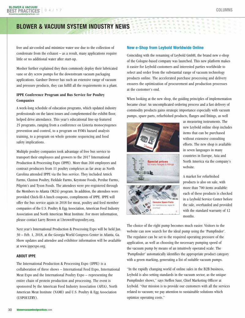
free and air-cooled and minimize water use due to the collection of
condensate from the exhaust – as a result, many applications require
little or no additional water after start-up.
Mosher further explained they then commonly deploy their lubricated
vane or dry screw pumps for the downstream vacuum packaging
applications. Gardner Denver has such an extensive range of vacuum
and pressure products, they can fulfill all the requirements in a plant.
IPPE Conference Program and Bus Service for Poultry Companies
A week-long schedule of education programs, which updated industry
professionals on the latest issues and complemented the exhibit floor,
helped drive attendance. This year’s educational line-up featured
25 programs, ranging from a conference on Listeria monocytogenes
prevention and control, to a program on FSMA hazard analysis
training, to a program on whole genome sequencing and food
safety implications.
Multiple poultry companies took advantage of free bus service to
transport their employees and growers to the 2017 International
Production & Processing Expo (IPPE). More than 260 employees and
contract producers from 11 poultry complexes as far away as North
Carolina attended IPPE via the bus service. They included Amick
Farms, Claxton Poultry, Fieldale Farms, Keystone Foods, Perdue Farms,
Pilgrim’s and Tyson Foods. The attendees were pre-registered through
the Members to Atlanta (M2A) program. In addition, the attendees were
provided Chick-fil-A lunch coupons, compliments of IPPE. IPPE will
offer the bus service again in 2018 for meat, poultry and feed member
companies of the U.S. Poultry & Egg Association, American Feed Industry
Association and North American Meat Institute. For more information,
please contact Larry Brown at [email protected].
Next year’s International Production & Processing Expo will be held Jan.
30 – Feb. 1, 2018, at the Georgia World Congress Center in Atlanta, Ga.
Show updates and attendee and exhibitor information will be available
at www.ippexpo.org.
ABOUT IPPE
The International Production & Processing Expo (IPPE) is a
collaboration of three shows – International Feed Expo, International
Meat Expo and the International Poultry Expo – representing the
entire chain of protein production and processing. The event is
sponsored by the American Feed Industry Association (AFIA), North
American Meat Institute (NAMI) and U.S. Poultry & Egg Association
(USPOULTRY).
New e-Shop from Leybold Worldwide Online
Coinciding with the renaming of Leybold GmbH, the brand new e-shop
of the Cologne-based company was launched. This new platform makes
it easier for Leybold customers and interested parties worldwide to
select and order from the substantial range of vacuum technology
products online. The accelerated purchase processing and delivery
ensures the optimization of procurement and production processes
at the customer's end.
When looking at the new shop, the guiding principles of implementation
became clear: An uncomplicated ordering process and a fast delivery of
commodity products gains strategic importance especially with vacuum
pumps, spare parts, refurbished products, flanges and fittings, as well
as measuring instruments. The
new Leybold online shop includes
items that can be purchased
without extensive consulting
efforts. The new shop is available
in seven languages in many
countries in Europe, Asia and
North America via the company's
website.
A market for refurbished
products is also on sale, with
more than 700 items available:
each of these products is checked
in a Leybold Service Center before
the sale, overhauled and provided
with the standard warranty of 12
months.
The choice of the right pump becomes much easier. Visitors to the
website can now search for the ideal pump using the ‘Pumpfinder’.
The regulator can be set to the required operating pressure of the
application, as well as choosing the necessary pumping speed of
the vacuum pump by means of an intuitively operated scale. The
‘Pumpfinder’ automatically identifies the appropriate product category
with a green marking, generating a list of suitable vacuum pumps.
“In the rapidly changing world of online sales in the B2B business,
Leybold is also setting standards in the vacuum sector, as the unique
Pumpfinder shows,” says Steffen Saur, Chief Marketing Officer at
Leybold. “Our mission is to provide our customers with all the services
related to vacuum; we pay attention to sustainable solutions which
optimize operating costs.”
BLOWER & VACUUM SYSTEM INDUSTRY NEWS
| 0 4 / 1 7
30 blowervacuumbestpractices.com
COLUMNS
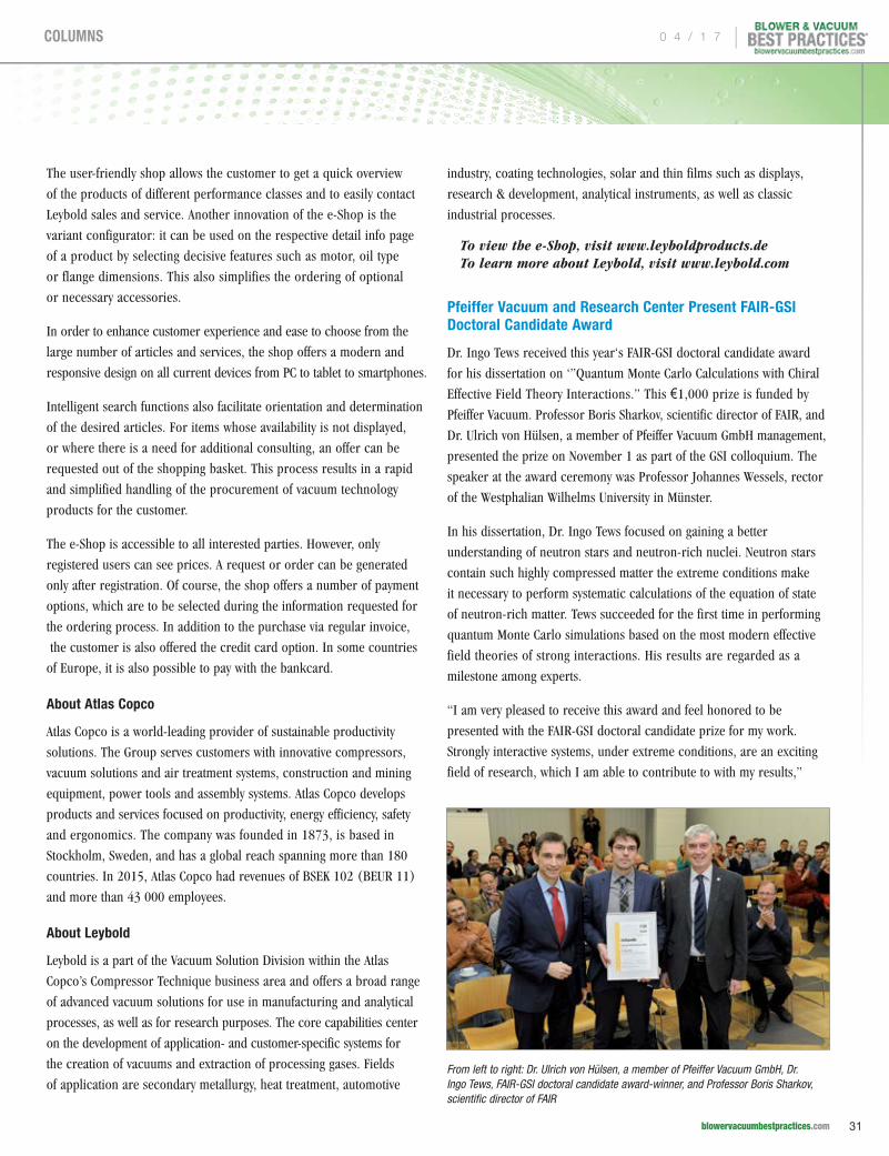
The user-friendly shop allows the customer to get a quick overview
of the products of different performance classes and to easily contact
Leybold sales and service. Another innovation of the e-Shop is the
variant configurator: it can be used on the respective detail info page
of a product by selecting decisive features such as motor, oil type
or flange dimensions. This also simplifies the ordering of optional
or necessary accessories.
In order to enhance customer experience and ease to choose from the
large number of articles and services, the shop offers a modern and
responsive design on all current devices from PC to tablet to smartphones.
Intelligent search functions also facilitate orientation and determination
of the desired articles. For items whose availability is not displayed,
or where there is a need for additional consulting, an offer can be
requested out of the shopping basket. This process results in a rapid
and simplified handling of the procurement of vacuum technology
products for the customer.
The e-Shop is accessible to all interested parties. However, only
registered users can see prices. A request or order can be generated
only after registration. Of course, the shop offers a number of payment
options, which are to be selected during the information requested for
the ordering process. In addition to the purchase via regular invoice,
the customer is also offered the credit card option. In some countries
of Europe, it is also possible to pay with the bankcard.
About Atlas Copco
Atlas Copco is a world-leading provider of sustainable productivity
solutions. The Group serves customers with innovative compressors,
vacuum solutions and air treatment systems, construction and mining
equipment, power tools and assembly systems. Atlas Copco develops
products and services focused on productivity, energy efficiency, safety
and ergonomics. The company was founded in 1873, is based in
Stockholm, Sweden, and has a global reach spanning more than 180
countries. In 2015, Atlas Copco had revenues of BSEK 102 (BEUR 11)
and more than 43 000 employees.
About Leybold
Leybold is a part of the Vacuum Solution Division within the Atlas
Copco’s Compressor Technique business area and offers a broad range
of advanced vacuum solutions for use in manufacturing and analytical
processes, as well as for research purposes. The core capabilities center
on the development of application- and customer-specific systems for
the creation of vacuums and extraction of processing gases. Fields
of application are secondary metallurgy, heat treatment, automotive
industry, coating technologies, solar and thin films such as displays,
research & development, analytical instruments, as well as classic
industrial processes.
To view the e-Shop, visit www.leyboldproducts.de To learn more about Leybold, visit www.leybold.com
Pfeiffer Vacuum and Research Center Present FAIR-GSI Doctoral Candidate Award
Dr. Ingo Tews received this year‘s FAIR-GSI doctoral candidate award
for his dissertation on ‘”Quantum Monte Carlo Calculations with Chiral
Effective Field Theory Interactions.” This €1,000 prize is funded by
Pfeiffer Vacuum. Professor Boris Sharkov, scientific director of FAIR, and
Dr. Ulrich von Hülsen, a member of Pfeiffer Vacuum GmbH management,
presented the prize on November 1 as part of the GSI colloquium. The
speaker at the award ceremony was Professor Johannes Wessels, rector
of the Westphalian Wilhelms University in Münster.
In his dissertation, Dr. Ingo Tews focused on gaining a better
understanding of neutron stars and neutron-rich nuclei. Neutron stars
contain such highly compressed matter the extreme conditions make
it necessary to perform systematic calculations of the equation of state
of neutron-rich matter. Tews succeeded for the first time in performing
quantum Monte Carlo simulations based on the most modern effective
field theories of strong interactions. His results are regarded as a
milestone among experts.
“I am very pleased to receive this award and feel honored to be
presented with the FAIR-GSI doctoral candidate prize for my work.
Strongly interactive systems, under extreme conditions, are an exciting
field of research, which I am able to contribute to with my results,”
From left to right: Dr. Ulrich von Hülsen, a member of Pfeiffer Vacuum GmbH, Dr. Ingo Tews, FAIR-GSI doctoral candidate award-winner, and Professor Boris Sharkov, scientific director of FAIR
0 4 / 1 7 |
31 blowervacuumbestpractices.com
COLUMNS

To subscribe visit blowervacuumbestpractices.com
F R E E S U B S C R I P T I O NDIGITAL EDITION FREE WORLDWIDE | PRINT EDITION FREE TO U.S. SUBSCRIBERS
Poultry & Meat Packaging • Pharmaceutical & Labs • Food Processing • Wastewater Aeration
Sustainable Energy Savings with Blower & Vacuum Best PracticesBlower & Vacuum Best Practices is a technical magazine dedicated to discovering Energy Savings in industrial blower and vacuum systems and in municipal wastewater aeration blower systems. Our editorial focus is on case studies and technical articles where application and system knowledge drives technology selection, creating energy savings in projects delivering excellent ROI’s.
“ A more recent innovation is to control the aeration blowers off of total air flow instead of header pressure.”
– Julia Gass, P.E., Black & Veatch (September 2016 Issue)
“ Busch designed a customized central vacuum system for the furniture manufacturer, consisting of eight identical Mink claw vacuum pumps, each equipped with a suction capacity of 300 m3/h.”
– Uli Merkle, Busch Vacuum Pumps and Systems (feature article in July 2016 Issue)
From WWTP Aeration Blowers to Centralized Vacuum SystemsOur readers have embraced energy management practices as the next step. Our diverse key subscribers work at multi-factory manufacturing organizations and are targets to consider options such as VSD vacuum pumps in newly centralized systems. On the municipal side, over 1,000+ operators at wastewater treatment plants (WWTP’s) and blower sales channels receive the magazine. Lastly, a growing group of industrial blower and vacuum OEM design engineers are looking for technologies able to improve their machines.
“Our engineering optimizes blower packages for each field – identifying, for example, the optimal conveying velocities for over 50 types of wheat flour!”
– Todd Smith, General Manager, Coperion K-Tron (Powder Show Report in a 2016 Issue)
2017 FOCUS INDUSTRIES!
Subscribe Now!
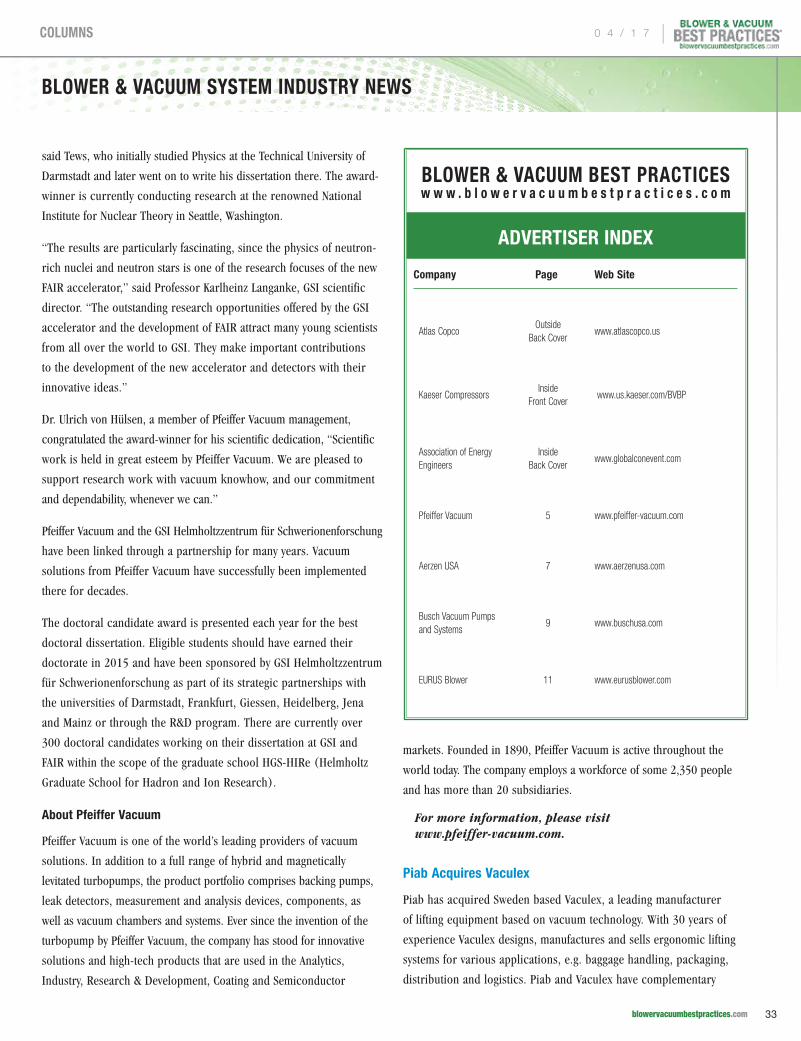
BLOWER & VACUUM SYSTEM INDUSTRY NEWS
said Tews, who initially studied Physics at the Technical University of
Darmstadt and later went on to write his dissertation there. The award-
winner is currently conducting research at the renowned National
Institute for Nuclear Theory in Seattle, Washington.
“The results are particularly fascinating, since the physics of neutron-
rich nuclei and neutron stars is one of the research focuses of the new
FAIR accelerator,” said Professor Karlheinz Langanke, GSI scientific
director. “The outstanding research opportunities offered by the GSI
accelerator and the development of FAIR attract many young scientists
from all over the world to GSI. They make important contributions
to the development of the new accelerator and detectors with their
innovative ideas.”
Dr. Ulrich von Hülsen, a member of Pfeiffer Vacuum management,
congratulated the award-winner for his scientific dedication, “Scientific
work is held in great esteem by Pfeiffer Vacuum. We are pleased to
support research work with vacuum knowhow, and our commitment
and dependability, whenever we can.”
Pfeiffer Vacuum and the GSI Helmholtzzentrum für Schwerionenforschung
have been linked through a partnership for many years. Vacuum
solutions from Pfeiffer Vacuum have successfully been implemented
there for decades.
The doctoral candidate award is presented each year for the best
doctoral dissertation. Eligible students should have earned their
doctorate in 2015 and have been sponsored by GSI Helmholtzzentrum
für Schwerionenforschung as part of its strategic partnerships with
the universities of Darmstadt, Frankfurt, Giessen, Heidelberg, Jena
and Mainz or through the R&D program. There are currently over
300 doctoral candidates working on their dissertation at GSI and
FAIR within the scope of the graduate school HGS-HIRe (Helmholtz
Graduate School for Hadron and Ion Research).
About Pfeiffer Vacuum
Pfeiffer Vacuum is one of the world’s leading providers of vacuum
solutions. In addition to a full range of hybrid and magnetically
levitated turbopumps, the product portfolio comprises backing pumps,
leak detectors, measurement and analysis devices, components, as
well as vacuum chambers and systems. Ever since the invention of the
turbopump by Pfeiffer Vacuum, the company has stood for innovative
solutions and high-tech products that are used in the Analytics,
Industry, Research & Development, Coating and Semiconductor
markets. Founded in 1890, Pfeiffer Vacuum is active throughout the
world today. The company employs a workforce of some 2,350 people
and has more than 20 subsidiaries.
For more information, please visit www.pfeiffer-vacuum.com.
Piab Acquires Vaculex
Piab has acquired Sweden based Vaculex, a leading manufacturer
of lifting equipment based on vacuum technology. With 30 years of
experience Vaculex designs, manufactures and sells ergonomic lifting
systems for various applications, e.g. baggage handling, packaging,
distribution and logistics. Piab and Vaculex have complementary
BLOWER & VACUUM BEST PRACTICESw w w . b l o w e r v a c u u m b e s t p r a c t i c e s . c o m
ADVERTISER INDEX
Company Page Web Site
Atlas CopcoOutside
Back Coverwww.atlascopco.us
Kaeser CompressorsInside
Front Cover www.us.kaeser.com/BVBP
Association of Energy Engineers
Inside Back Cover
www.globalconevent.com
Pfeiffer Vacuum 5 www.pfeiffer-vacuum.com
Aerzen USA 7 www.aerzenusa.com
Busch Vacuum Pumps and Systems
9 www.buschusa.com
EURUS Blower 11 www.eurusblower.com
To subscribe visit blowervacuumbestpractices.com
F R E E S U B S C R I P T I O NDIGITAL EDITION FREE WORLDWIDE | PRINT EDITION FREE TO U.S. SUBSCRIBERS
Poultry & Meat Packaging • Pharmaceutical & Labs • Food Processing • Wastewater Aeration
Sustainable Energy Savings with Blower & Vacuum Best PracticesBlower & Vacuum Best Practices is a technical magazine dedicated to discovering Energy Savings in industrial blower and vacuum systems and in municipal wastewater aeration blower systems. Our editorial focus is on case studies and technical articles where application and system knowledge drives technology selection, creating energy savings in projects delivering excellent ROI’s.
“ A more recent innovation is to control the aeration blowers off of total air flow instead of header pressure.”
– Julia Gass, P.E., Black & Veatch (September 2016 Issue)
“ Busch designed a customized central vacuum system for the furniture manufacturer, consisting of eight identical Mink claw vacuum pumps, each equipped with a suction capacity of 300 m3/h.”
– Uli Merkle, Busch Vacuum Pumps and Systems (feature article in July 2016 Issue)
From WWTP Aeration Blowers to Centralized Vacuum SystemsOur readers have embraced energy management practices as the next step. Our diverse key subscribers work at multi-factory manufacturing organizations and are targets to consider options such as VSD vacuum pumps in newly centralized systems. On the municipal side, over 1,000+ operators at wastewater treatment plants (WWTP’s) and blower sales channels receive the magazine. Lastly, a growing group of industrial blower and vacuum OEM design engineers are looking for technologies able to improve their machines.
“Our engineering optimizes blower packages for each field – identifying, for example, the optimal conveying velocities for over 50 types of wheat flour!”
– Todd Smith, General Manager, Coperion K-Tron (Powder Show Report in a 2016 Issue)
2017 FOCUS INDUSTRIES!
Subscribe Now!
0 4 / 1 7 |
33 blowervacuumbestpractices.com
COLUMNS
product offerings and the combination will enable accelerated growth.
Both companies have strong brands and are recognized for leading
technology platforms, innovation, safety and high quality products.
Piab has 13 sales offices and more than 900 partners with well-
balanced geographical and segment coverage. Vaculex has a strong
high-quality product portfolio that is well positioned in its target
segments via its network of sales offices and distributors. The
combined company will become a stronger partner for customers
world-wide, by providing an extended product portfolio and joint
expertise with global reach.
“We are convinced that this is a great match. Our partners around
the globe have repeatedly requested Vaculex type products. This
market is growing rapidly due to manual lifting operations being
increasingly automated. We are very excited about the growth
prospects and strength of the combined company”, says Anders
Lindqvist, CEO of Piab Group.
“Piab’s long history of innovation in vacuum technology and global
market access, combined with Vaculex’s innovative product range,
will shape a new and stronger business partner. We strongly believe
that the new formed company will serve the market even better.
I am really looking forward to working with the combined group”,
says Ronny Holmsten, CEO at Vaculex.
The transaction took place on the 30th of December, 2016.
About Piab
Established in 1951, Piab designs innovative vacuum solutions that
improve the energy-efficiency, productivity, and working environments
of vacuum users around the world. As a reliable partner to many of
the world’s largest manufacturers, Piab develops and manufactures a
complete line of vacuum pumps, vacuum accessories, vacuum conveyors
and suction cups for a variety of automated material handling and
factory automation processes. Piab utilizes COAX®, a completely new
dimension in vacuum technology, in many of its original products
and solutions. COAX® cartridges are smaller, more energy efficient
and more reliable than conventional ejectors, and can be integrated
directly into machinery. This allows for the design of a flexible, modular
vacuum system. Piab is a worldwide organization with subsidiaries and
distributors in almost 70 countries. Its headquarters are in Sweden.
For more information about Piab, visit www.piab.com.
Blower & Vacuum Best Practices is published quarterly and mailed together with Compressed Air Best Practices®. Compressed Air Best Practices® (USPS# 17130) is published monthly except January-February combined by Smith Onandia Communications LLC, 37 McMurray Rd., Suite 106, Pittsburgh, PA 15241. Periodicals postage paid at Pittsburgh, PA and additional mailing offices. POSTMASTER: Send address changes to: Compressed Air Best Practices®, 37 McMurray Rd, Suite 106, Pittsburgh, PA 15241.
Compressed Air Best Practices® is a trademark of Smith Onandia Communications, LLC. Publisher cannot be held liable for non-delivery due to circumstances beyond its control. No refunds. SUBSCRIPTIONS: Qualified reader subscriptions are accepted from compressed air professionals, plant managers, plant engineers, service and maintenance managers, operations managers, auditors, and energy engineers in manufacturing plants and engineering/consulting firms in the U.S. Contact Patricia Smith for subscription information at tel: 412-980-9902 or email: [email protected]. REPRINTS: Reprints are available on a custom basis, contact Patricia Smith for a price quotation at Tel: 412-980-9902 or email: [email protected]. All rights are reserved. The contents of this publication may not be reproduced in whole or in part without consent of Smith Onandia Communications LLC. Smith Onandia Communications LLC. does not assume and hereby disclaims any liability to any person for any loss or damage caused by errors or omissions in the material contained herein, regardless of whether such errors result from negligence, accident, or any other cause whatsoever. Printed in the U.S.A.
BLOWER & VACUUM BEST PRACTICES www.b lower vacuumbestpract ices .com
Advertising &: Editorial
Rod Smith [email protected] Tel: 412-980-9901
Subscriptions & : Administration
Patricia Smith [email protected] Tel: 412-980-9902
A Publication of: Smith Onandia Communications LLC 37 McMurray Rd. Suite 106 Pittsburgh, PA 15241 SFI-00993
Contact Rod Smith for ad rates: [email protected], Tel: 412-980-9901
BLOWER & VACUUM SYSTEM INDUSTRY NEWS
| 0 4 / 1 7
34 blowervacuumbestpractices.com
COLUMNS

Other Energy Events
June 7-8, 2017Long Beach Convention Center, Long Beach, California
www.globalconevent.com www.energycongress.com
ATTENDANCE | 770.447.5083 x226
SEMINARS | 770.925.9633
EXHIBITS | 770.279.4386
CONFERENCE - SEMINARS - TRADE SHOW
www.energyevent.com
Energy Management, Power, Buildings, and Clean Technologies ExpoExplore promising new technologies, compare energy supply options, and learn innovative implementation strategies.
Presented By
Compressed_Air_EMC_full_02-17.indd 1 1/30/17 1:58 PM
INNOVATIVE, INTELLIGENT, INDUSTRY CHANGINGA New Generation of Vacuum Pumps Superior performance and dependability,energy efficiency beyond compare, noise levels half that of the competition, and reduced environmental impact.
www.atlascopco.us – 866-546-3588