Embed Size (px)
Citation preview
Geology
doi: 10.1130/0091-7613(1989)017<0345:IPFNFP>2.3.CO;2 1989;17;345-348Geology
Jon Olson and David D. Pollard Inferring paleostresses from natural fracture patterns: A new method
Email alerting servicesthis article
to receive free e-mail alerts when new articles citewww.gsapubs.org/cgi/alertsclick
Subscribe to subscribe to Geologywww.gsapubs.org/subscriptions/click
Permission request to contact GSAhttp://www.geosociety.org/pubs/copyrt.htm#gsaclick
presented in this publication do not reflect official positions of the Society.scientists worldwide, regardless of their race, citizenship, gender, religion, or political viewpoint. Opinions citation. GSA provides this and other forums for the presentation of diverse opinions and positions byon their own or their organization's Web site providing the posting includes a reference to the article's full science. This file may not be posted to any Web site, but authors may post the abstracts only of their articlesunlimited copies of items in GSA's journals for noncommercial use in classrooms to further education and use a single figure, a single table, and/or a brief paragraph of text in subsequent works and to makeemployment. Individual scientists are hereby granted permission, without fees or further requests to GSA, to Copyright not claimed on content prepared wholly by U.S. government employees within scope of their
Notes
Geological Society of America
on July 5, 2014geology.gsapubs.orgDownloaded from on July 5, 2014geology.gsapubs.orgDownloaded from
Inferring paleostresses from natural fracture patterns: A new method
Jon Olson, David D. Pollard Depar tment of Appl ied Earth Sciences, Stanford University, Stanford, Cal i fornia 94305
ABSTRACT We introduce a method to infer the remote differential stress magnitude from the curva-
ture of overlapping echelon fracture traces. The curving paths of overlapping echelon cracks imply the predominance of local crack-induced stresses over remote stresses during propaga-tion. Nearly straight crack paths imply the controlling influence of a remote compressive crack-parallel differential stress. This method is used to interpret complex joint patterns mapped in sedimentary rock. It is also applied to the problem of fracture-pattern generation using computer models.
INTRODUCTION Field geologists are commonly confronted
with the task of inferring the causative stresses for a particular geologic structure from its geometry. Methods have been devised that re-late joint orientation to the principal stress tra-jectories (Engelder and Geiser, 1980) and joint dilation to the difference between the internal fluid pressure and remote least compressive stress (Segall and Pollard, 1983). We introduce a method that relates the shape of overlapping joint traces to the difference between the greatest and least compressive stress. Given a map of natural fracture traces, one can use this method to infer the differential stress that acted during propagation.
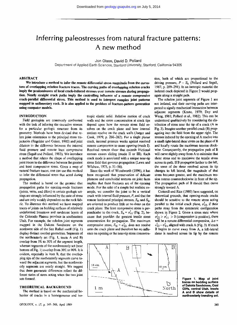
The method is based on the premise that propagation paths for opening-mode fractures (joints, veins, and dikes) in certain geologic set-tings are strongly influenced by the state of stress and are only weakly dependent on the rock fab-ric. To illustrate this method we have mapped traces of joints on bedding surfaces of relatively undeformed limestone and sandstone layers of the Colorado Plateau province in southeastern Utah. For example, the echelon joint segments mapped in the Dakota Sandstone on the northwest side of the San Rafael swell (Fig. 1) display distinct overlap geometries. Segments of the northeasterly set (Fig. 1, insets A and B) overlap from 5% to 30% of the segment length, whereas segments of the northwesterly set (near bottom of Fig. 1) overlap from 30% to 90%. It is evident, especially in inset B, that the overlap-ping tips of the northeasterly segments curve to-ward the adjacent segments, but the northwest-erly segments are nearly straight. We suggest that these geometric differences reflect the dif-ferent states of stress acting when the two joint sets formed.
THEORETICAL BACKGROUND The method is based on the mechanical be-
havior of cracks in a homogeneous and iso-
tropic elastic solid. Relative motion of crack walls and the stress concentration at crack tips depend upon how the remote stress field re-solves on the crack plane and how internal stresses resolve on the crack walls (Jaeger and Cook, 1979, p. 266-282). For a single planar crack, internal pressure works against resolved remote compression to cause opening (mode I). Resolved remote shear that exceeds frictional stresses causes sliding (mode II or III). Each crack mode is associated with a unique near-tip stress field that governs propagation (Lawn and Wilshaw, 1975, p. 51-56).
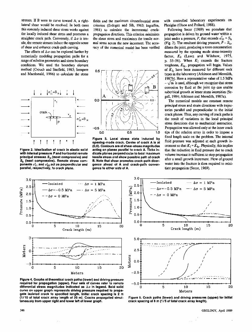
Since the work of Woodworth (1896), it has been recognized that preservation of delicate plumose and conchoidal textures on joint faces implies that these fractures are of the opening mode. For the sake of a simple but realistic ex-ample, we consider the joint to be a vertical crack with internal fluid pressure, P, and that the remote horizontal principal stresses, S H and S^, are oriented to produce little or no shear on the crack plane. The least compressive stress is per-pendicular to the crack, S h = a \ \ (Fig. 2), be-cause that provides the greatest tensile stress concentration for propagation. The maximum compressive stress, S H = 022, does not resolve onto the crack plane and therefore has no influ-ence on opening or the near-tip stress concentra-
tion, both of which are proportional to the driving pressure, P - S^ (Pollard and Segall, 1987, p. 289-291). In an isotropic material the isolated crack depicted in Figure 2 would prop-agate along a straight path.
The echelon joint segments of Figure 1 are not isolated, and their curving paths are inter-preted to signify mechanical interaction between adjacent segments (Kranz, 1979; Dey and Wang, 1981; Pollard et al., 1982). This can be understood qualitatively by considering the dis-tribution of stress near the tip of a crack (A in Fig. 3). Imagine another parallel crack (B) prop-agating into the field from the upper right. The stresses induced by the opening of A resolve into a small right-lateral shear stress on the plane of B and locally rotate the maximum tension clock-wise. Consequently, the propagation path of B will curve slightly away from A to minimize that shear stress and to maximize the tensile stress across its path. If B propagates farther to the left, the sense of the shear resolved across its tip changes to left lateral, the magnitude of that stress becomes greater, and the maximum ten-sion rotates counterclockwise in front of the tip. The propagation path of B should then curve strongly toward A.
Cotterell and Rice (1980) have suggested, on theoretical grounds, that opening-mode cracks should be sensitive to the remote stress acting parallel to the initial crack plane, a'22, if their paths stray from the symmetric configuration shown in Figure 2. Given a stress state where a22 > a l l > 0 (compression is positive), there will be a remote differential compression, A 0 = a 22 - o ii , aligned with crack A (Fig. 3). If crack B begins to curve away from A, a left-lateral shear is resolved across its tip by the remote
Figure 1. Map of joint traces on bedding surface o< Dakota Sandstone, Coal Cliffs, central Utah. Insets A and B show details of northeasterly trending set.
.V 10 cm \
\BT A \ V V 10 cm \ *
1 m •
V \ T
\ N o r t h
GEOLOGY, v. 17, p. 345-348, April 1989 345
on July 5, 2014geology.gsapubs.orgDownloaded from
stresses. If B were to curve toward A, a right-lateral shear would be resolved. In both cases this remotely induced shear stress works against the locally induced shear stress and promotes a straighter crack path. Conversely, if ACT is ten-sile, the remote stresses induce the opposite sense of shear and enhance crack-path curving.
The effects of ACT can be explored further by numerically modeling propagation paths for a range of echelon geometries and stress boundary conditions. We used the boundary element method (Crouch and Starfield, 1983; Sempere and Macdonald, 1986) to calculate the stress
i 1 K -M 1 I
t t t t t t t Figure 2. Idealization of crack in elastic solid with internal pressure Pand horizontal remote principal stresses SH (most compressive) and Sh (least compressive). Remote stress com-ponents o\ i and a'22 act as perpendicular and parallel, respectively, to crack plane.
fields and the maximum circumferential stress criterion (Erdogan and Sih, 1963; Ingraffea, 1981) to calculate the incremental crack-propagation directions. This criterion minimizes the shear stress and maximizes the tensile nor-mal stress across the new increment. The accu-racy of the numerical model has been verified
Figure 3. Local stress state induced by opening-mode crack. Center of crack A is at (0,0). Contours are of shear-stress magnitudes acting on planes parallel to crack A. Ticks in-dicate planes perpendicular to local maximum tensile stress and show possible path of crack B. Note that shear promotes crack-path diver-gence ahead of A and crack-path conver-gence to either side of A.
with controlled laboratory experiments on Plexiglas (Olson and Pollard, 1988).
Following Secor (1969) we postulate that propagation is driven by ground water within a joint under a pressure, P, that exceeds a n = Sh (Fig. 2). The resultant driving pressure, P - S ^ , dilates the joint, producing a stress concentration measured by the opening mode stress-intensity factor, Ky (Lawn and Wilshaw, 1975, p. 55-56). When K\ exceeds the fracture toughness, Kic, propagation will begin. Values of Kyz have been measured for different rock types in the laboratory (Atkinson and Meredith, 1987b). Here a representative value of 1.5 MPa - \ / in is used, although we recognize that stress corrosion by fluid at the joint tip can enable subcritical growth at lesser stress intensities (Se-gall, 1984; Atkinson and Meredith, 1987a).
The numerical models use constant remote principal stress and strain directions with trajec-tories parallel and perpendicular to the initial crack planes. Thus, any curving of crack paths is the result of variations in the local principal stress directions due to mechanical interaction. Propagation was allowed only at the inner crack tips of the echelon array in order to impose a fixed length scale on the problem. The internal fluid pressure was adjusted at each growth in-crement so that Ki = Kic. Physically, this implies that the reduction in fluid pressure due to crack volume increase is sufficient to stop propagation after a small growth increment. Flow of ground water into the fracture is then required to reini-tiate propagation (Secor, 1969).
a cu 2
Q) U 3 M VI ID U cu
3 . 0 - 3 . 0
I s o l a t e d
— A C T = - 0 . 5 M P a
- -ACT = 0 M P a
• • ACT = 1 M P a
— - ACT = 5 M P a
10 Crack length (m)
15 20
a ,
0.0
I s o l a t e d • • • ACT = 1 M P a
Acr= — 0 . 5 M P a — - ACT = 5 M P a
\ - -ACT = 0 M P a
/ /
/ /
1 1 1 11—• •
—•—1—1—1—1—•—1—1—•— I • • • i—1—1—1—1—1— 10
C r a c k l e n g t h ( m ) 1 5 20
w Si V
-u a)
S
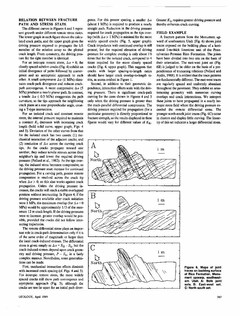
Figure 4. Graphs of theoretical crack paths (lower) and driving pressure required for propagation (upper). Four sets of curves refer to remote differential stress magnitudes indicated as A a in legend. Bold solid curve on upper graph represents driving pressure required to propa-gate isolated crack to specified length. Initial crack spacing is 2 m (1/10 of total crack array length of 20 m). Cracks propagated simul-taneously from upper right and lower left of lower graph.
- 5 . 0
Figure 5. Crack paths (lower) and driving pressures (upper) for initial crack spacing of 8 m (1 / 5 of total crack array length).
346 GEOLOGY, April 1989
on July 5, 2014geology.gsapubs.orgDownloaded from
RELATION BETWEEN FRACTURE PATH AND STRESS STATE
The different curves in Figures 4 and 5 repre-sent growth under different remote stress states. The lower graph in each figure shows the calcu-lated crack paths, and the upper graph gives the driving pressure required to propagate the left member of the echelon array to the plotted crack length. From symmetry, the driving pres-sure for the right member is identical.
For an isotropic remote stress, A a = 0, the closely spaced echelon cracks (Fig. 4) exhibit an initial divergence of paths followed by conver-gence and an asymptotic approach to each other. A small compressive ACT (1 MPa) elimi-nates crack-path divergence and reduces crack-path convergence. A more compressive ACT (5 MPa) produces a nearly planar path. In contrast, a tensile ACT (-0.5 MPa) exaggerates the path curvature, so the tips approach the neighboring crack plane at a near perpendicular angle, creat-ing a T-type intersection.
For an isolated crack and constant remote stress, the internal pressure required to maintain a constant K\ decreases with increasing crack length (bold solid curve, upper graph, Figs. 4 and 5). Deviation of the other curves from that for the isolated crack has two causes: (1) me-chanical interaction of the adjacent cracks; and (2) resolution of ACT across the curving crack tips. As the cracks propagate toward one another, they induce tensile stresses across their neighbor's tip and lower the required driving pressure (Pollard et al., 1982). As the tips over-lap, the induced stress becomes compressive, so the driving pressure must increase for continued propagation. For a curving path, greater remote compression is resolved across the crack tip when ACT > 0, so this also works against crack propagation. Unless the driving pressure in-creases, the cracks will reach a stable overlapped position without intersecting. In Figure 4, if the driving pressure available after crack initiation were 1 MPa, the maximum overlap (for ACT = 0 MPa) would be approximately 1/3 of the max-imum 12 m crack length. If the driving pressures were to increase, greater overlap would be pos-sible, provided the cracks did not follow inter-secting trajectories.
The remote differential stress plays an impor-tant role in crack-path determination only if it is of the same order of magnitude or larger than the local crack-induced stresses. The differential stress is given simply as ACT = S H - S^, but the crack-induced stresses depend upon crack geom-etry and driving pressure, P - Sh, in a fairly complex manner. Nonetheless, some generaliza-tions can be made.
First, mechanical interaction effects diminish with increased crack spacing (cf. Figs. 4 and 5). For isotropic remote stress, the more widely spaced cracks still show path convergence and asymptotic approach (Fig. 5), although the cracks are too far apart for an initial path diver-
gence. For this greater spacing, a smaller ACT (about 1 MPa) is required to produce a nearly straight path. Reduction in the driving pressure required for crack propagation as the tips over-lap (with ACT 3* 1 MPa) is minimal for the more widely spaced cracks (Fig. 5, upper graph). Crack impedance with continued overlap is still present, but the required elevation of driving pressure for complete overlap is only about 1 xh times that for the isolated crack, compared to 4 times required for the more closely spaced cracks (Fig. 4, upper graph). This suggests that cracks with larger spacing-to-length ratios should have larger crack overlap-to-length ra-tios, as seems evident in Figure 1.
Second, in addition to their geometric de-pendence, interaction effects scale with the driv-ing pressure. There is significant crack-path curving for the cases shown in Figures 4 and 5 only when the driving pressure is greater than the crack-parallel differential compression. The driving pressure required for propagation (for a particular geometry) is directly proportional to fracture strength, so the results displayed in these figures would vary for different values of K\c.
Greater K\c requires greater driving pressure and thereby enhances crack curving.
FIELD EXAMPLE A fracture pattern from the Monument up-
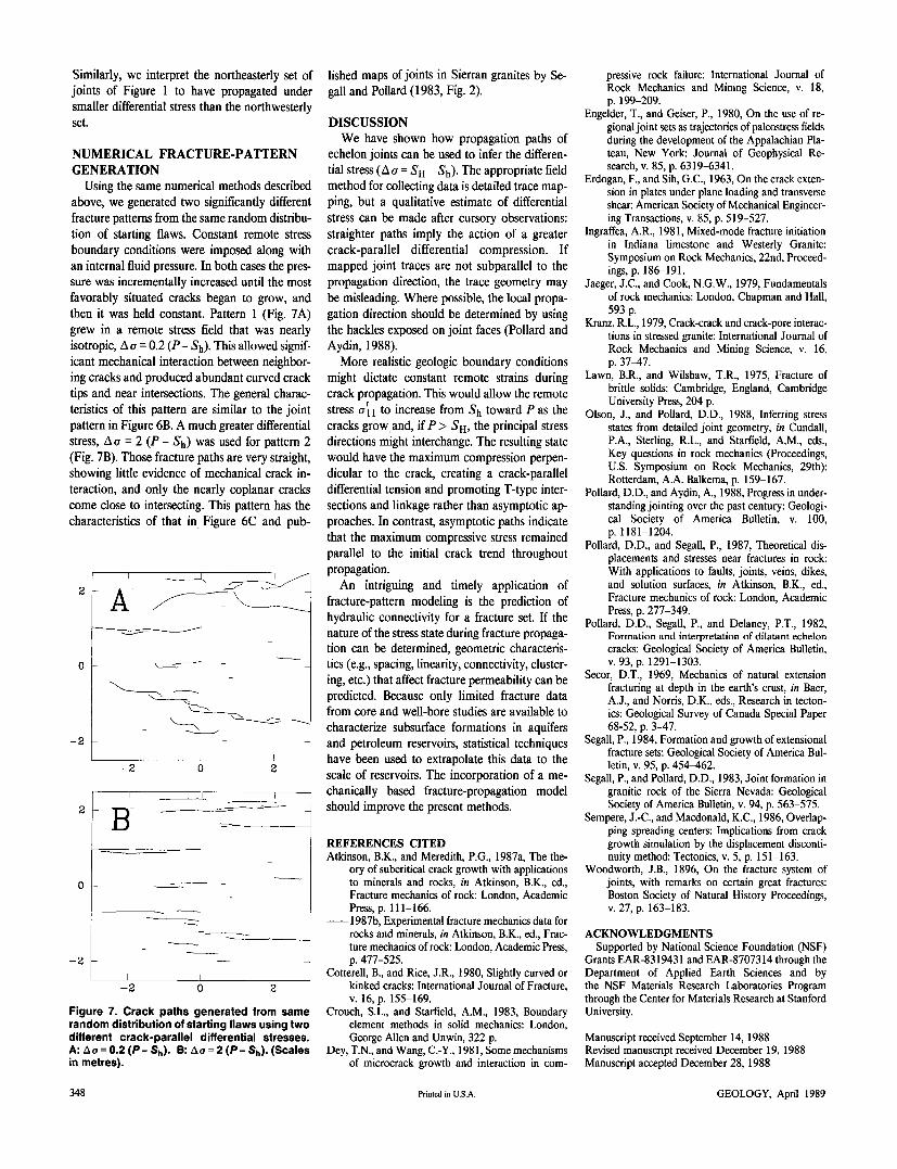
ward of southeastern Utah (Fig. 6) shows joint traces exposed on the bedding plane of a hori-zontal 1-m-thick limestone unit of the Penn-sylvanian-Permian Rico Formation. The joints have been divided into two sets on the basis of their orientation. The east-west joint set (Fig. 6B) is judged to be older on the basis of a pre-ponderance of truncating relations (Pollard and Aydin, 1988). It is evident that the trace patterns are fundamentally different. The east-west traces are regularly spaced and uniformly abundant throughout the pavement. They exhibit an anas-tomosing geometry with numerous curving overlaps and crack intersections. We interpret these joints to have propagated in a nearly iso-tropic stress field where the driving pressure ex-ceeded the remote differential stress. The younger north-south joint traces (Fig. 6C) occur in clusters and display little curving. The linear-ity of this set indicates a larger differential stress.
Figure 6. Maps of joint traces on bedding surface of Rico Formation, Monu-ment upwarp, southeast-ern Utah. A: Both joint sets. B: East-west set. C: North-south set.
346 GEOLOGY, April 1989
on July 5, 2014geology.gsapubs.orgDownloaded from
Similarly, we interpret the northeasterly set of joints of Figure 1 to have propagated under smaller differential stress than the northwesterly set.
NUMERICAL FRACTURE-PATTERN GENERATION
Using the same numerical methods described above, we generated two significantly different fracture patterns from the same random distribu-tion of starting flaws. Constant remote stress boundary conditions were imposed along with an internal fluid pressure. In both cases the pres-sure was incrementally increased until the most favorably situated cracks began to grow, and then it was held constant. Pattern 1 (Fig. 7A) grew in a remote stress field that was nearly isotropic, ACT = 0.2 (P - Sh). This allowed signif-icant mechanical interaction between neighbor-ing cracks and produced abundant curved crack tips and near intersections. The general charac-teristics of this pattern are similar to the joint pattern in Figure 6B. A much greater differential stress, A a = 2 (P - S h ) was used for pattern 2 (Fig. 7B). Those fracture paths are very straight, showing little evidence of mechanical crack in-teraction, and only the nearly coplanar cracks come close to intersecting. This pattern has the characteristics of that in Figure 6C and pub-
Figure 7. Crack paths generated from same random distribution of starting flaws using two different crack-parallel differential stresses. A: Ao = 0.2 ( P - Sh). B: Ao = 2 ( P - Sh). (Scales in metres).
lished maps of joints in Sierran granites by Se-gall and Pollard (1983, Fig. 2).
DISCUSSION We have shown how propagation paths of
echelon joints can be used to infer the differen-tial stress (Aa = S H - 5h). The appropriate field method for collecting data is detailed trace map-ping, but a qualitative estimate of differential stress can be made after cursory observations: straighter paths imply the action of a greater crack-parallel differential compression. If mapped joint traces are not subparallel to the propagation direction, the trace geometry may be misleading. Where possible, the local propa-gation direction should be determined by using the hackles exposed on joint faces (Pollard and Aydin, 1988).
More realistic geologic boundary conditions might dictate constant remote strains during crack propagation. This would allow the remote stress or i i to increase from toward P as the cracks grow and, if P > Sh, the principal stress directions might interchange. The resulting state would have the maximum compression perpen-dicular to the crack, creating a crack-parallel differential tension and promoting T-type inter-sections and linkage rather than asymptotic ap-proaches. In contrast, asymptotic paths indicate that the maximum compressive stress remained parallel to the initial crack trend throughout propagation.
An intriguing and timely application of fracture-pattern modeling is the prediction of hydraulic connectivity for a fracture set. If the nature of the stress state during fracture propaga-tion can be determined, geometric characteris-tics (e.g., spacing, linearity, connectivity, cluster-ing, etc.) that affect fracture permeability can be predicted. Because only limited fracture data from core and well-bore studies are available to characterize subsurface formations in aquifers and petroleum reservoirs, statistical techniques have been used to extrapolate this data to the scale of reservoirs. The incorporation of a me-chanically based fracture-propagation model should improve the present methods.
REFERENCES CITED Atkinson, B.K., and Meredith, P.G., 1987a, The the-
ory of subcritical crack growth with applications to minerals and rocks, in Atkinson, B.K., ed., Fracture mechanics of rock: London, Academic Press, p. 111-166. 1987b, Experimental fracture mechanics data for rocks and minerals, in Atkinson, B.K., ed., Frac-ture mechanics of rock: London, Academic Press, p. 477-525.
Cotterell, B., and Rice, J.R., 1980, Slightly curved or kinked cracks: International Journal of Fracture, v. 16, p. 155-169.
Crouch, S.L., and Starfield, A.M., 1983, Boundary element methods in solid mechanics: London, George Allen and Unwin, 322 p.
Dey, T.N., and Wang, C.-Y., 1981, Some mechanisms of microcrack growth and interaction in com-
pressive rock failure: International Journal of Rock Mechanics and Mining Science, v. 18, p. 199-209.
Engelder, T., and Geiser, P., 1980, On the use of re-gional joint sets as trajectories of paleostress fields during the development of the Appalachian Pla-teau, New York: Journal of Geophysical Re-search, v. 85, p. 6319-6341.
Erdogan, F., and Sih, G.C., 1963, On the crack exten-sion in plates under plane loading and transverse shear: American Society of Mechanical Engineer-ing Transactions, v. 85, p. 519-527.
Ingraffea, A.R., 1981, Mixed-mode fracture initiation in Indiana limestone and Westerly Granite: Symposium on Rock Mechanics, 22nd, Proceed-ings,?. 186-191.
Jaeger, J.C., and Cook, N.G.W., 1979, Fundamentals of rock mechanics: London, Chapman and Hall, 593 p.
Kranz, R.L., 1979, Crack-crack and crack-pore interac-tions in stressed granite: International Journal of Rock Mechanics and Mining Science, v. 16, p. 37-47.
Lawn, B.R., and Wilshaw, T.R., 1975, Fracture of brittle solids: Cambridge, England, Cambridge University Press, 204 p.
Olson, J., and Pollard, D.D., 1988, Inferring stress states from detailed joint geometry, in Cundall, P.A., Sterling, R.L., and Starfield, A.M., eds., Key questions in rock mechanics (Proceedings, U.S. Symposium on Rock Mechanics, 29th): Rotterdam, A.A. Balkema, p. 159-167.
Pollard, D.D., and Aydin, A., 1988, Progress in under-standing jointing over the past century: Geologi-cal Society of America Bulletin, v. 100, p. 1181-1204.
Pollard, D.D., and Segall, P., 1987, Theoretical dis-placements and stresses near fractures in rock: With applications to faults, joints, veins, dikes, and solution surfaces, in Atkinson, B.K., ed., Fracture mechanics of rock: London, Academic Press, p. 277-349.
Pollard, D.D., Segall, P., and Delaney, P.T., 1982, Formation and interpretation of dilatant echelon cracks: Geological Society of America Bulletin, v. 93, p. 1291-1303.
Secor, D.T., 1969, Mechanics of natural extension fracturing at depth in the earth's crust, in Baer, A.J., and Norris, D.K., eds., Research in tecton-ics: Geological Survey of Canada Special Paper 68-52, p. 3-47.
Segall, P., 1984, Formation and growth of extensional fracture sets: Geological Society of America Bul-letin, v. 95, p. 454-462.
Segall, P., and Pollard, D.D., 1983, Joint formation in granitic rock of the Sierra Nevada: Geological Society of America Bulletin, v. 94, p. 563-575.
Sempere, J.-C., and Macdonald, K.C., 1986, Overlap-ping spreading centers: Implications from crack growth simulation by the displacement disconti-nuity method: Tectonics, v. 5, p. 151-163.
Woodworth, J.B., 1896, On the fracture system of joints, with remarks on certain great fractures: Boston Society of Natural History Proceedings, v. 27, p. 163-183.
ACKNOWLEDGMENTS Supported by National Science Foundation (NSF)
Grants EAR-8319431 and EAR-8707314 through the Department of Applied Earth Sciences and by the NSF Materials Research Laboratories Program through the Center for Materials Research at Stanford University.
Manuscript received September 14, 1988 Revised manuscript received December 19, 1988 Manuscript accepted December 28, 1988
348 Printed in U.S.A. GEOLOGY, April 1989
on July 5, 2014geology.gsapubs.orgDownloaded from
![Case Report of a Tibial Plateau Fracture Extending Through the … · describes tibia plateau fracture patterns and serves to guide operative treatment [5]. This fracture pattern](https://img.pdfslide.net/doc/110x75/5d1e74de88c99335368d6437/case-report-of-a-tibial-plateau-fracture-extending-through-the-describes-tibia.jpg)