Embed Size (px)
Citation preview

&
Infield Engineering 30” Grumman F4F Wildcat
© Copyright 2009 Paul Kohlmann. All rights reserved. 2 of 21
Thanks very much for your purchase of the Infield Engineering Grumman F4F Wildcat produced by Zeke’s Park Scale Models! The goal behind the design of this kit was to create a lightweight, full-house airframe with a scale outline that could easily be flown on a softball field. The only deviation from scale was a slight increase in the size of the tail to give it a little more authority while clearing the bases of Zeros! This Wildcat was designed in 3D CAD specifically for lasercutting to produce a quick-building, sturdy structure with a low parts count. Its a lot like a classic stick-and-tissue model from days gone by but because of the use of the laser its parts are much more intricate and fully interlocked. The result builds faster and lighter than those kits from back in the day. This instruction book will walk you through building the Wildcat. Although the construction is straightforward, the model is designed for builders with intermediate or better skills. With that in mind, please read through this document prior to starting your build--it may help you avoid a mistake or two along the way. These instructions will focus on framing and assembly. Because there are a myriad of ways to install the electronics and controls, these items will be left to the builder. A buildthread on RCGroups at http://www.rcgroups.com/forums/showthread.php?t=927089 addresses how these details were handled for the prototypes with photos and commentary. Items needed to complete your Grumman Wildcat: 1 micro receiver 2 – 3 sub micro servos (.33oz/9 grams or less recommended) 1 electronic speed controller ~24g brushless motor and a 8x6 APC slow flyer propeller 3/32” square balsa or basswood for leading edges Sullivan’s .025” Gold-n-rod for ailerons (optional—torque rods may be substituted) .040” music wire for control rods 1 roll of light weight covering material Misc. building supplies (glue, razor blades, etc.)
Grumman F4F Wildcat Specifications
Length 23 1/2”
Wing Span 30 3/8”
Wing Area ~139 in2
Weight 7.5 ~ 10.0 oz.
Wing Loading 10.8 – 10.3 oz/ft2
Power System ~24g outrunner w/ 8x6 APC prop
Control Functions Rudder, elevator, ailerons &
throttle (rudder may be omitted)
Battery Pack 2S 800 mAh or 3S 600 mAh
Infield Engineering 30” Grumman F4F Wildcat
© Copyright 2009 Paul Kohlmann. All rights reserved. 3 of 21
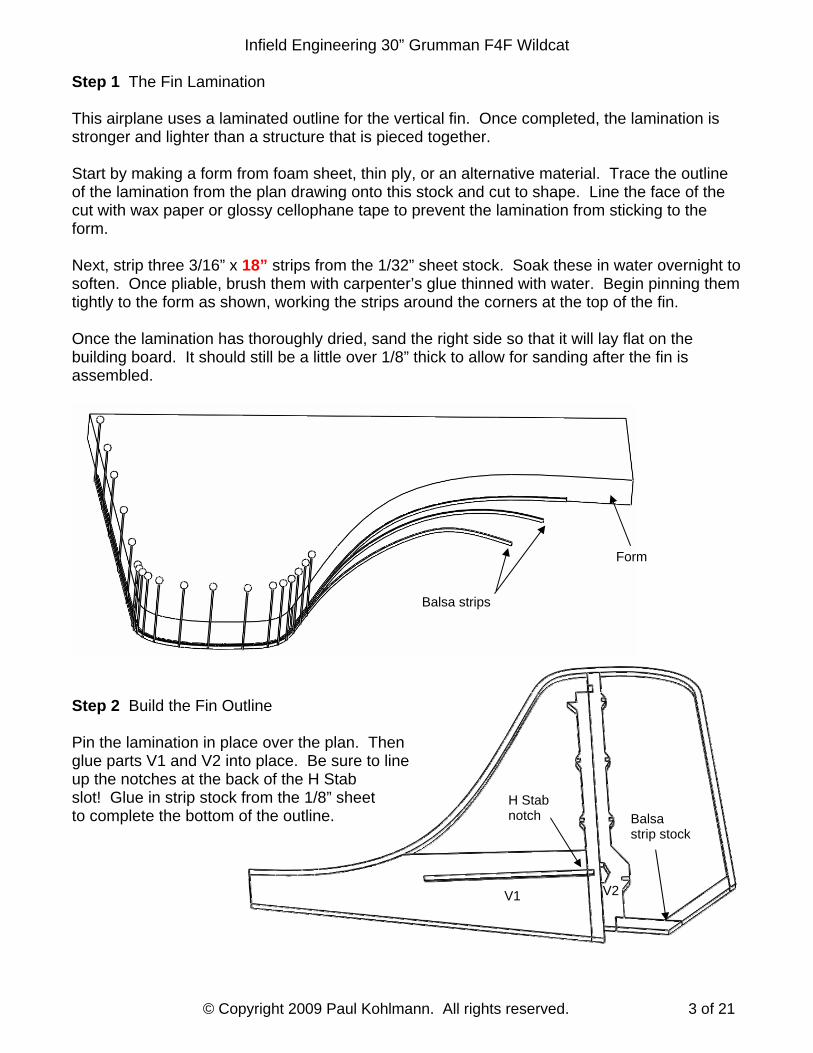
Step 1 The Fin Lamination This airplane uses a laminated outline for the vertical fin. Once completed, the lamination is stronger and lighter than a structure that is pieced together. Start by making a form from foam sheet, thin ply, or an alternative material. Trace the outline of the lamination from the plan drawing onto this stock and cut to shape. Line the face of the cut with wax paper or glossy cellophane tape to prevent the lamination from sticking to the form. Next, strip three 3/16” x 18” strips from the 1/32” sheet stock. Soak these in water overnight to soften. Once pliable, brush them with carpenter’s glue thinned with water. Begin pinning them tightly to the form as shown, working the strips around the corners at the top of the fin. Once the lamination has thoroughly dried, sand the right side so that it will lay flat on the building board. It should still be a little over 1/8” thick to allow for sanding after the fin is assembled.
Step 2 Build the Fin Outline Pin the lamination in place over the plan. Then glue parts V1 and V2 into place. Be sure to line up the notches at the back of the H Stab slot! Glue in strip stock from the 1/8” sheet to complete the bottom of the outline.
Form
Balsa strips
Balsa strip stock
H Stab notch
V1 V2

Infield Engineering 30” Grumman F4F Wildcat
© Copyright 2009 Paul Kohlmann. All rights reserved. 4 of 21
Step 3 Complete the Fin Fill in the horizontal edge at the top left of the fin with strip stock from the 1/8” sheet but don’t glue where they meet (unless the rudder will be fixed). Fill in the 1/16” bracing. Unpin when the assembly is dry and sand to shape. Split as shown to free the rudder. Step 4 Prepare the Rudder Joint Sand a radius on both sides of the vertical parting line where the rudder will be hinged.
Split Rudder Here
Split Rudder Here
Sand radius for hinge
1/16” balsa bracing
Infield Engineering 30” Grumman F4F Wildcat
© Copyright 2009 Paul Kohlmann. All rights reserved. 5 of 21
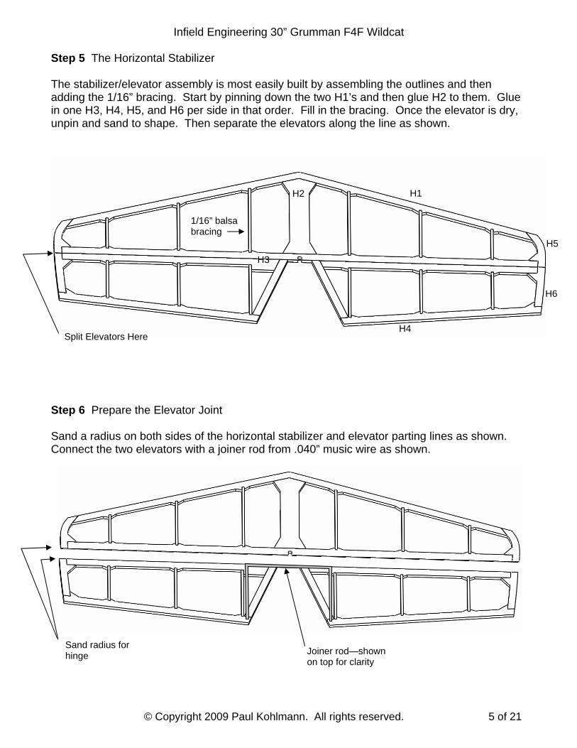
Step 5 The Horizontal Stabilizer The stabilizer/elevator assembly is most easily built by assembling the outlines and then adding the 1/16” bracing. Start by pinning down the two H1’s and then glue H2 to them. Glue in one H3, H4, H5, and H6 per side in that order. Fill in the bracing. Once the elevator is dry, unpin and sand to shape. Then separate the elevators along the line as shown. Step 6 Prepare the Elevator Joint Sand a radius on both sides of the horizontal stabilizer and elevator parting lines as shown. Connect the two elevators with a joiner rod from .040” music wire as shown.
Split Elevators Here
Sand radius for hinge Joiner rod—shown
on top for clarity
H1 H2
H3
H4
H5
H6
1/16” balsa bracing
Infield Engineering 30” Grumman F4F Wildcat
© Copyright 2009 Paul Kohlmann. All rights reserved. 6 of 21
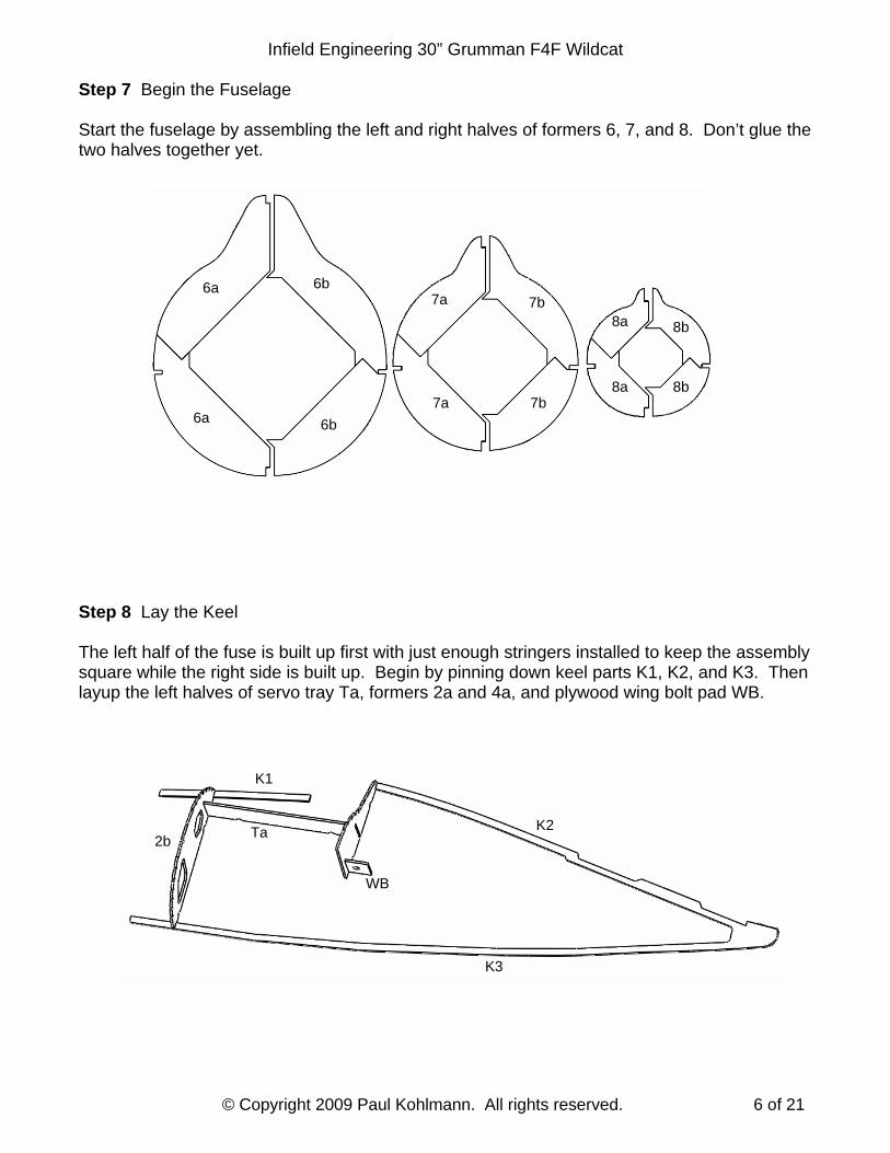
Step 7 Begin the Fuselage Start the fuselage by assembling the left and right halves of formers 6, 7, and 8. Don’t glue the two halves together yet. Step 8 Lay the Keel The left half of the fuse is built up first with just enough stringers installed to keep the assembly square while the right side is built up. Begin by pinning down keel parts K1, K2, and K3. Then layup the left halves of servo tray Ta, formers 2a and 4a, and plywood wing bolt pad WB.
6a
8b 8a 7b 7a
6b
6a 6b
7a 7b 8a 8b
2b
K1
Ta K2
WB
K3
Infield Engineering 30” Grumman F4F Wildcat
© Copyright 2009 Paul Kohlmann. All rights reserved. 7 of 21
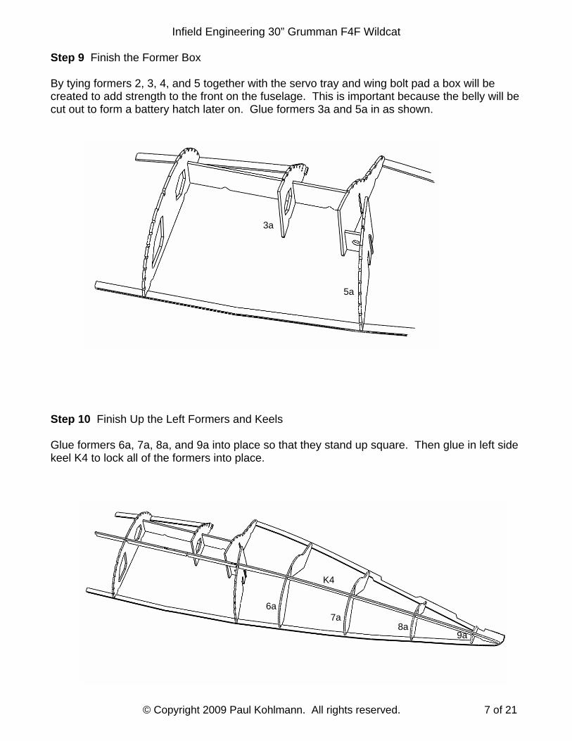
Step 9 Finish the Former Box By tying formers 2, 3, 4, and 5 together with the servo tray and wing bolt pad a box will be created to add strength to the front on the fuselage. This is important because the belly will be cut out to form a battery hatch later on. Glue formers 3a and 5a in as shown. Step 10 Finish Up the Left Formers and Keels Glue formers 6a, 7a, 8a, and 9a into place so that they stand up square. Then glue in left side keel K4 to lock all of the formers into place.
5a
3a
9a
7a 6a
K4
8a

Infield Engineering 30” Grumman F4F Wildcat
© Copyright 2009 Paul Kohlmann. All rights reserved. 8 of 21
Step 11 Install the Wing Pocket Panel
Once the wing pocket panel WP is fastened to the former box, the front half of the fuse becomes strong enough to be unpinned. Add a few 1/16” square balsa stringers and the back half will support itself as well. You’ll notice that only the front formers are
notched for the stringers. This is to allow the stringers to lay more naturally to minimize stresses which might twist the fuselage.
Step 12 Add the Belly Formers The three belly formers B2, B3, and B5 are each installed in one piece to ensure that the belly is strong. These formers will have to be flexed, which can be a little tricky. For best results, follow the notes below. Be careful not to glue B2 or B5 to their adjacent formers--the gap between them will soon become the hatch parting line.
Clip B5 into the belly keel first. Pinch B5 to former 5 near the belly keel, then slide B5 into the side keel notch.
Clip B3 into side keel K4, then slide B3 into the belly keel notch.
Clip B2 into bottom keel K3, then slide the sides of B2 up to meet former 2.
WP
B5 B3
B2
K3
Infield Engineering 30” Grumman F4F Wildcat
© Copyright 2009 Paul Kohlmann. All rights reserved. 9 of 21
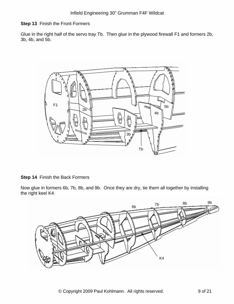
Step 13 Finish the Front Formers Glue in the right half of the servo tray Tb. Then glue in the plywood firewall F1 and formers 2b, 3b, 4b, and 5b.
Step 14 Finish the Back Formers Now glue in formers 6b, 7b, 8b, and 9b. Once they are dry, tie them all together by installing the right keel K4.
4b
5b
Tb
2b F1
3b
9b 8b 7b 6b
K4
Infield Engineering 30” Grumman F4F Wildcat
© Copyright 2009 Paul Kohlmann. All rights reserved. 10 of 21
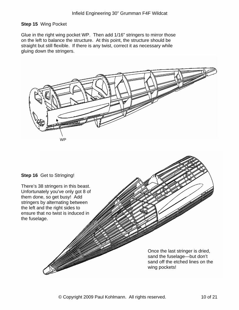
Step 15 Wing Pocket Glue in the right wing pocket WP. Then add 1/16” stringers to mirror those on the left to balance the structure. At this point, the structure should be straight but still flexible. If there is any twist, correct it as necessary while gluing down the stringers. Step 16 Get to Stringing!
There’s 38 stringers in this beast. Unfortunately you’ve only got 8 of them done, so get busy! Add stringers by alternating between the left and the right sides to ensure that no twist is induced in the fuselage.
Once the last stringer is dried, sand the fuselage—but don’t sand off the etched lines on the wing pockets!
WP
Infield Engineering 30” Grumman F4F Wildcat
© Copyright 2009 Paul Kohlmann. All rights reserved. 11 of 21
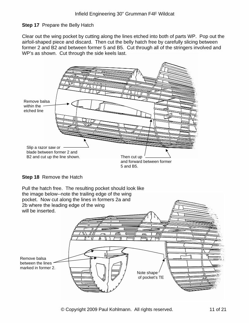
Step 17 Prepare the Belly Hatch Clear out the wing pocket by cutting along the lines etched into both of parts WP. Pop out the airfoil-shaped piece and discard. Then cut the belly hatch free by carefully slicing between former 2 and B2 and between former 5 and B5. Cut through all of the stringers involved and WP’s as shown. Cut through the side keels last. Step 18 Remove the Hatch Pull the hatch free. The resulting pocket should look like the image below--note the trailing edge of the wing pocket. Now cut along the lines in formers 2a and 2b where the leading edge of the wing will be inserted.
Slip a razor saw or blade between former 2 and B2 and cut up the line shown. Then cut up
and forward between former 5 and B5.
Remove balsa within the etched line
Remove balsa between the lines marked in former 2.
Note shape of pocket’s TE
Infield Engineering 30” Grumman F4F Wildcat
© Copyright 2009 Paul Kohlmann. All rights reserved. 12 of 21
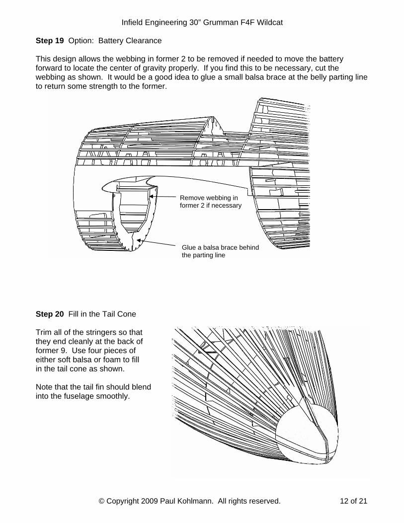
Step 19 Option: Battery Clearance
This design allows the webbing in former 2 to be removed if needed to move the battery forward to locate the center of gravity properly. If you find this to be necessary, cut the webbing as shown. It would be a good idea to glue a small balsa brace at the belly parting line to return some strength to the former. Step 20 Fill in the Tail Cone Trim all of the stringers so that they end cleanly at the back of former 9. Use four pieces of either soft balsa or foam to fill in the tail cone as shown. Note that the tail fin should blend into the fuselage smoothly.
Glue a balsa brace behind the parting line
Remove webbing in former 2 if necessary
Infield Engineering 30” Grumman F4F Wildcat
© Copyright 2009 Paul Kohlmann. All rights reserved. 13 of 21
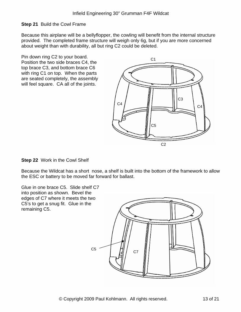
Step 21 Build the Cowl Frame Because this airplane will be a bellyflopper, the cowling will benefit from the internal structure provided. The completed frame structure will weigh only 6g, but if you are more concerned about weight than with durability, all but ring C2 could be deleted. Pin down ring C2 to your board. Position the two side braces C4, the top brace C3, and bottom brace C6 with ring C1 on top. When the parts are seated completely, the assembly will feel square. CA all of the joints. Step 22 Work in the Cowl Shelf Because the Wildcat has a short nose, a shelf is built into the bottom of the framework to allow the ESC or battery to be moved far forward for ballast. Glue in one brace C5. Slide shelf C7 into position as shown. Bevel the edges of C7 where it meets the two C5’s to get a snug fit. Glue in the remaining C5.
C5
C4 C4
C3
C2
C1
C5 C7
Infield Engineering 30” Grumman F4F Wildcat
© Copyright 2009 Paul Kohlmann. All rights reserved. 14 of 21
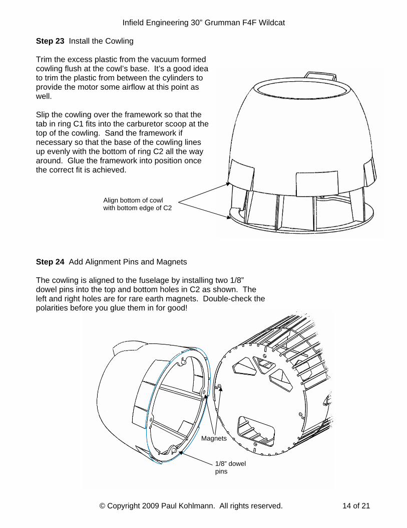
Step 23 Install the Cowling Trim the excess plastic from the vacuum formed cowling flush at the cowl’s base. It’s a good idea to trim the plastic from between the cylinders to provide the motor some airflow at this point as well. Slip the cowling over the framework so that the tab in ring C1 fits into the carburetor scoop at the top of the cowling. Sand the framework if necessary so that the base of the cowling lines up evenly with the bottom of ring C2 all the way around. Glue the framework into position once the correct fit is achieved.
Step 24 Add Alignment Pins and Magnets The cowling is aligned to the fuselage by installing two 1/8” dowel pins into the top and bottom holes in C2 as shown. The left and right holes are for rare earth magnets. Double-check the polarities before you glue them in for good!
Align bottom of cowl with bottom edge of C2
1/8” dowel pins
Magnets
Infield Engineering 30” Grumman F4F Wildcat
© Copyright 2009 Paul Kohlmann. All rights reserved. 15 of 21
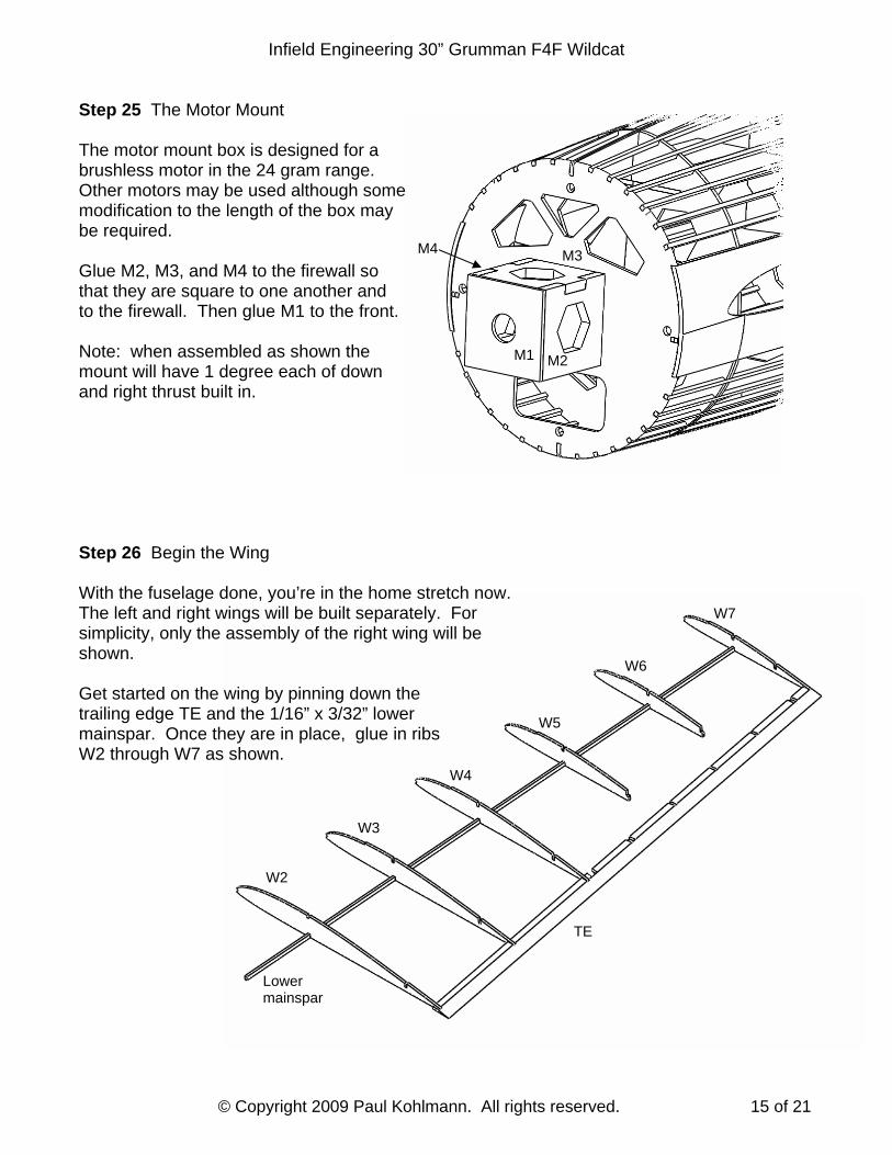
Step 25 The Motor Mount
The motor mount box is designed for a brushless motor in the 24 gram range. Other motors may be used although some modification to the length of the box may be required. Glue M2, M3, and M4 to the firewall so that they are square to one another and to the firewall. Then glue M1 to the front. Note: when assembled as shown the mount will have 1 degree each of down and right thrust built in.
Step 26 Begin the Wing With the fuselage done, you’re in the home stretch now. The left and right wings will be built separately. For simplicity, only the assembly of the right wing will be shown. Get started on the wing by pinning down the trailing edge TE and the 1/16” x 3/32” lower mainspar. Once they are in place, glue in ribs W2 through W7 as shown.
M1
M3 M4
M2
W7
W6
W5
W4
W3
W2
Lower mainspar
TE
Infield Engineering 30” Grumman F4F Wildcat
© Copyright 2009 Paul Kohlmann. All rights reserved. 16 of 21
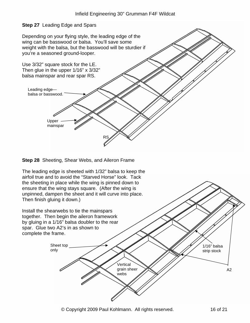
Step 27 Leading Edge and Spars Depending on your flying style, the leading edge of the wing can be basswood or balsa. You’ll save some weight with the balsa, but the basswood will be sturdier if you’re a seasoned ground-looper. Use 3/32” square stock for the LE. Then glue in the upper 1/16” x 3/32” balsa mainspar and rear spar RS. Step 28 Sheeting, Shear Webs, and Aileron Frame The leading edge is sheeted with 1/32” balsa to keep the airfoil true and to avoid the “Starved Horse” look. Tack the sheeting in place while the wing is pinned down to ensure that the wing stays square. (After the wing is unpinned, dampen the sheet and it will curve into place. Then finish gluing it down.) Install the shearwebs to tie the mainspars together. Then begin the aileron framework by gluing in a 1/16” balsa doubler to the rear spar. Glue two A2’s in as shown to complete the frame.
Leading edge—balsa or basswood.
RS
Upper mainspar
Vertical grain sheer webs
1/16” balsa strip stock
A2
Sheet top only
Infield Engineering 30” Grumman F4F Wildcat
© Copyright 2009 Paul Kohlmann. All rights reserved. 17 of 21
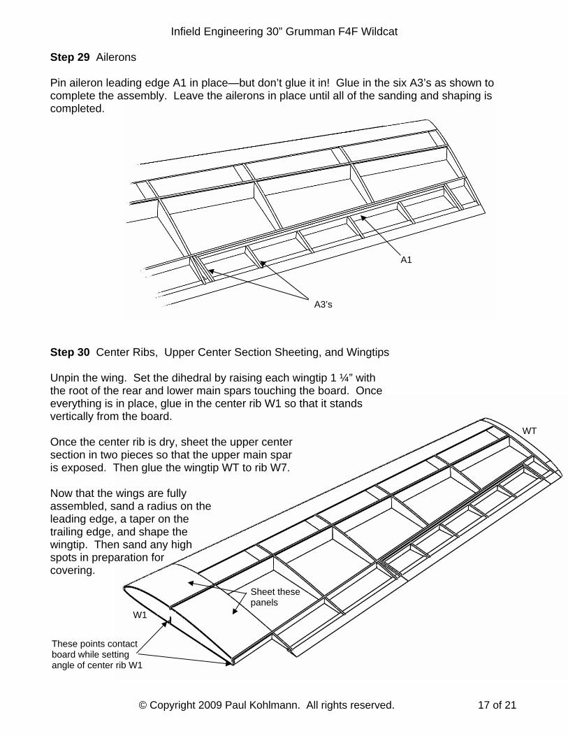
Step 29 Ailerons Pin aileron leading edge A1 in place—but don’t glue it in! Glue in the six A3’s as shown to complete the assembly. Leave the ailerons in place until all of the sanding and shaping is completed.
Step 30 Center Ribs, Upper Center Section Sheeting, and Wingtips Unpin the wing. Set the dihedral by raising each wingtip 1 ¼” with the root of the rear and lower main spars touching the board. Once everything is in place, glue in the center rib W1 so that it stands vertically from the board. Once the center rib is dry, sheet the upper center section in two pieces so that the upper main spar is exposed. Then glue the wingtip WT to rib W7. Now that the wings are fully assembled, sand a radius on the leading edge, a taper on the trailing edge, and shape the wingtip. Then sand any high spots in preparation for covering.
A1
A3’s
WT
W1
These points contact board while setting angle of center rib W1
Sheet these panels
Infield Engineering 30” Grumman F4F Wildcat
© Copyright 2009 Paul Kohlmann. All rights reserved. 18 of 21
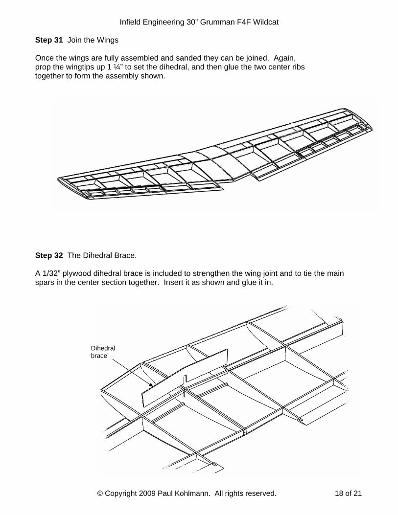
Step 31 Join the Wings Once the wings are fully assembled and sanded they can be joined. Again, prop the wingtips up 1 ¼” to set the dihedral, and then glue the two center ribs together to form the assembly shown. Step 32 The Dihedral Brace. A 1/32” plywood dihedral brace is included to strengthen the wing joint and to tie the main spars in the center section together. Insert it as shown and glue it in.
Dihedral brace
Infield Engineering 30” Grumman F4F Wildcat
© Copyright 2009 Paul Kohlmann. All rights reserved. 19 of 21
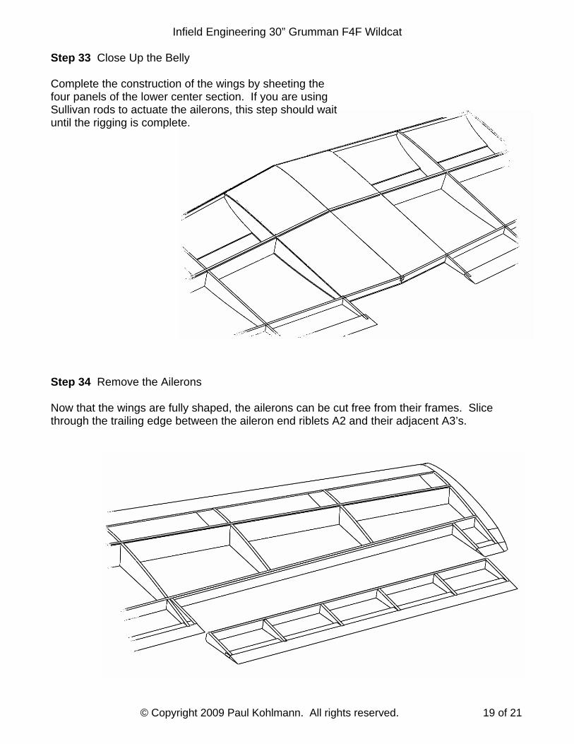
Step 33 Close Up the Belly Complete the construction of the wings by sheeting the four panels of the lower center section. If you are using Sullivan rods to actuate the ailerons, this step should wait until the rigging is complete. Step 34 Remove the Ailerons Now that the wings are fully shaped, the ailerons can be cut free from their frames. Slice through the trailing edge between the aileron end riblets A2 and their adjacent A3’s.
Infield Engineering 30” Grumman F4F Wildcat
© Copyright 2009 Paul Kohlmann. All rights reserved. 20 of 21
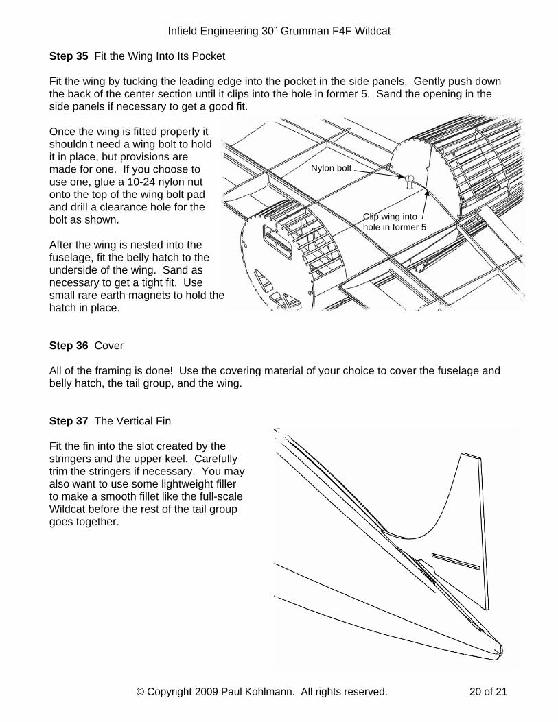
Step 35 Fit the Wing Into Its Pocket Fit the wing by tucking the leading edge into the pocket in the side panels. Gently push down the back of the center section until it clips into the hole in former 5. Sand the opening in the side panels if necessary to get a good fit. Once the wing is fitted properly it shouldn’t need a wing bolt to hold it in place, but provisions are made for one. If you choose to use one, glue a 10-24 nylon nut onto the top of the wing bolt pad and drill a clearance hole for the bolt as shown. After the wing is nested into the fuselage, fit the belly hatch to the underside of the wing. Sand as necessary to get a tight fit. Use small rare earth magnets to hold the hatch in place. Step 36 Cover All of the framing is done! Use the covering material of your choice to cover the fuselage and belly hatch, the tail group, and the wing. Step 37 The Vertical Fin Fit the fin into the slot created by the stringers and the upper keel. Carefully trim the stringers if necessary. You may also want to use some lightweight filler to make a smooth fillet like the full-scale Wildcat before the rest of the tail group goes together.
Clip wing into hole in former 5
Nylon bolt
Infield Engineering 30” Grumman F4F Wildcat
© Copyright 2009 Paul Kohlmann. All rights reserved. 21 of 21
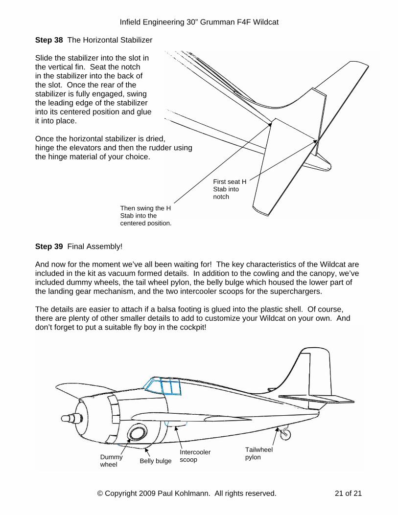
Step 38 The Horizontal Stabilizer Slide the stabilizer into the slot in the vertical fin. Seat the notch in the stabilizer into the back of the slot. Once the rear of the stabilizer is fully engaged, swing the leading edge of the stabilizer into its centered position and glue it into place. Once the horizontal stabilizer is dried, hinge the elevators and then the rudder using the hinge material of your choice. Step 39 Final Assembly! And now for the moment we’ve all been waiting for! The key characteristics of the Wildcat are included in the kit as vacuum formed details. In addition to the cowling and the canopy, we’ve included dummy wheels, the tail wheel pylon, the belly bulge which housed the lower part of the landing gear mechanism, and the two intercooler scoops for the superchargers. The details are easier to attach if a balsa footing is glued into the plastic shell. Of course, there are plenty of other smaller details to add to customize your Wildcat on your own. And don’t forget to put a suitable fly boy in the cockpit!
Then swing the H Stab into the centered position.
Dummy wheel Belly bulge
Intercooler scoop
Tailwheel pylon
First seat H Stab into notch