Embed Size (px)
Citation preview
1
INFLUENCE OF ACOUSTIC REFLECTION ON FLUTTER
STABILITY OF AN EMBEDDED BLADE ROW
F. Zhao*, J. Nipkau
† & M.Vahdati
*
*Mechanical Engineering Department, Imperial College London, London, UK
†Compressor Aeroelasticity, Rolls-Royce Deutschland, Germany
ABSTRACT
The aim of this work is to understand the effects of acoustic reflections on flutter stability
of an embedded rotor in a multi-stage compressor. To achieve this goal, flutter analysis of an
embedded rotor blade in a high pressure compressor is undertaken using a validated 3D
unsteady RANS solver with mesh movement. In the first part of this work, flutter
computations are performed on the rotor with and without the presence of its adjacent blade
rows and the influence of reflections on aerodynamic damping of the embedded row is
studied. In the second part of this work reflective boundary conditions are used to reflect
pressure waves from known locations. A wave-splitting procedure is performed to split the
unsteady pressure into an outgoing wave and a reflected wave. Using this technique a
relationship between the phase of the reflected wave and the susceptibility to flutter is
established.
NOMENCLATURE
1F First flap mode
S1 Stator 1
S2 Stator 2
f Frequency of vibration (Hz)
V Relative air velocity (m/s)
ND Nodal diameter
R2 Rotor 2
RANS Reynolds-averaged Navier–Stokes
c Chord (m)
k Reduced frequency (𝑘 = 2𝜋𝑓𝑐 𝑉⁄ )
INTRODUCTION
Prediction of aeroelastic stability (i.e. flutter) of an embedded rotor in a multi-stage compressor
is studied in this work. The term embedded refers to the fact that the blade row of interest is
surrounded by other blade rows. Although there have been extensive studies about aeroelastic
stability of compressor or turbine blades (He, 1994) (Vahdati & Imergun, 1996) (Srinivasan, 1997)
(Vahdati, et al., 2001) (Doi & Alonso, 2002) (McBean, et al., 2005) (Vahdati, et al., 2011), very
limited work can be found regarding the effects of rotor-stator acoustic interaction on flutter
stability of embedded blades (Li & He, 2005) (Hsu, et al., 2012) (Schoenenborn & Ashcroft, 2014).
For an embedded rotor within a multi-stage compressor, flutter can occur when the acoustic
pressure fields upstream and/or downstream of the blade row are cut-on (i.e. wave propagates
without attenuation). Acoustic pressure waves generated by rotor vibration propagate between (and
are reflected at) blade rows, influencing the flutter stability of the embedded rotor. Conventional
flutter analysis of such a blade row usually involves unsteady computation of an isolated annulus at
the flow condition of interest with the inflow and outflow boundary conditions treated as non-
reflective type. Such an analysis ignores the effect of acoustic reflection from adjacent (or not
immediately adjacent) blade rows and structures, and is only valid when the acoustic fields
upstream and downstream of the blade row are cut-off (i.e. amplitude of the wave is attenuated
exponentially as it propagates axially). Accurate prediction of flutter stability of such an embedded
blade row taking into account acoustic reflection effect would require unsteady computation of
Proceedings of
11th European Conference on Turbomachinery Fluid dynamics & Thermodynamics
ETC11, March 23-27, 2015, Madrid, Spain
OPEN ACCESS
Downloaded from www.euroturbo.eu Copyright © by the Authors
2
multi-row full annulus models, which poses high demands on both computational time and
resources and thus cannot be used routinely in the design stage. Moreover, the use of blisks is
becoming more common in modern aero-engine designs. Such structures have very low mechanical
damping and hence are more susceptible to flutter instability. Therefore accurate prediction of
flutter stability in a multi-row environment becomes vital in multi-stage compressor, fan and turbine
design.
In a recent EU collaborative project (Fransson & Vogt, 2011) several organisations attempted to
predict the flutter of a core compressor test case but there was no general agreement about whether
the blade would be stable or not. The discrepancy in prediction, besides the use of different
computational codes, comes from the use of different boundary condition types (i.e. reflective or
non-reflective) and the number of blade rows that were included in the model, indicating that this is
not an established technique. In a more recent study of the influence of intake on fan blade flutter
stability (Vahdati, et al., 2014), flutter analysis of a fan was undertaken which is ‘embedded’ by the
upstream intake structure as well as the downstream outlet guide vanes (OGV). In this study, the
downstream acoustic field was cut-off within the frequency range of interest, thus acoustic
interaction occurred only at the leading edge of the fan. It was established that acoustic reflection
from intake can play an important part in flutter of fans, manifesting as the so-called ‘flutter bite’
phenomenon where the blade can experience flutter instability well away from the stall boundary.
Depending on the phasing of the outgoing and reflected pressure waves, reflection from intake
couples with the near fan pressure field which would result in either beneficial or detrimental
effects on its flutter stability. This type of flutter does not necessarily require unfavourable coupling
between blade flow and mode shape (i.e. classical flutter) or the occurrence of flow separation (i.e.
stall flutter). Further investigations and physical explanations are required to understand flutter
behaviour of embedded blade rows subjected to acoustic reflections from bladed structures.
The main objective of this work is to study the effects of acoustic reflections from adjacent
blade rows on flutter stability of an embedded blade row. Moreover, physical insights are to be
obtained regarding the relationships between blade vibration, propagation and reflection of acoustic
waves and blade flutter stability. To achieve this goal, aeroelastic analysis was undertaken using a
validated 3D unsteady CFD code with mesh movement, and wave-splitting was performed to
understand the characteristics of wave propagation and reflection. The decomposition of
propagating 3D eigenmodes (upstream propagating acoustic mode, downstream propagating
acoustic, vortical and entropy modes) is performed by solving the General Eigenvalue Problem
resulting from the discretisation of the linearised Navier-Stokes equations. The splitting of modes is
achieved by identifying the direction of mode propagation based on their respective eigenvalues (i.e.
axial wavenumber), and by evaluating the corresponding amplitude of unsteady pressure and
entropy perturbations. For the wave-split method used the reader is referred to (Moinier & Giles,
2005). The understanding gained could be used to draw out some guidelines for future compressor
designs and devise low fidelity models for embedded blade row flutter prediction.
COMPUTATIONAL MODEL AND METHODS
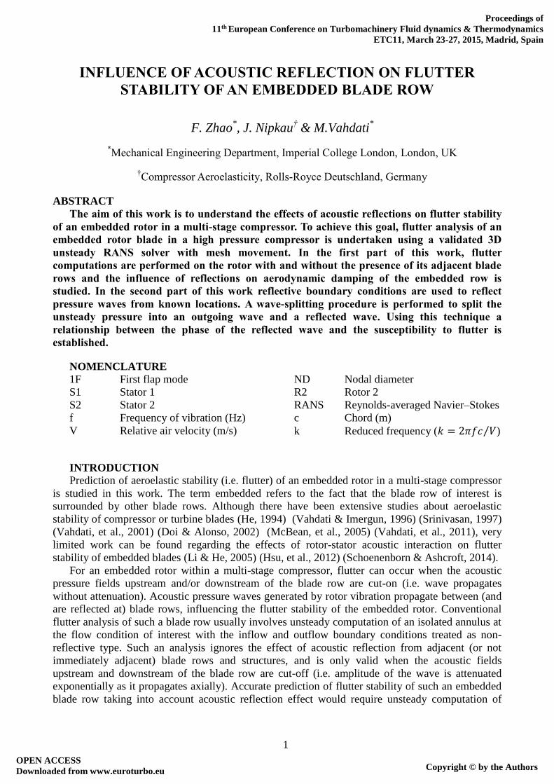
Test Case and Computational Model
Figure 1: (a) 9-stage E3E high pressure compressor, (b) the measured flutter event
3
During a working line acceleration vibration survey at sea level conditions of the E3E axial flow
core engine designed and tested by Rolls-Royce Deutschland (Klinger, et al., 2008) (Klinger, et al.,
2011), nonsynchronous vibration was measured at high speed on rotor 2 blade (R2) embedded
within a 9-stage HP compressor (Figure 1). Analysis of Blade tip timing (BTT) and casing mounted
pressure transducer signals confirmed the cause to be 1F/0ND (first flap mode) aeroelastic flutter at
a reduced frequency of k=1.2. This phenomenon was very unusual as it occurred in a very narrow
speed range (see Figure 1b) at a condition well away from stall (as will be shown in the next section)
and at a high reduced frequency (typical flutter events in 1F mode were observed for reduced
frequencies less than about k=0.4 (Srinivasan, 1997)). Moreover, for the measured flutter mode
(1F/0ND) the acoustic fields upstream and downstream of the rotor were both cut-on (0ND mode is
always cut-on), indicating that the main cause of flutter (Vahdati & Cumpsty, 2012) is not related to
flow/mode shape interactions. Flutter analyses were carried out to determine the cause of instability
and to avoid future damage to the engine. Computation of the isolated rotor row using non-
reflective boundary conditions showed no indication of negative aerodynamic damping (i.e. flutter)
for all NDs. Moreover, predicted stability of the problematic rotor was found to be highly
dependent on the boundary condition style used (reflective or non-reflective). Hence acoustic
reflection from adjacent blade rows was considered to be a cause of the flutter event. This high
pressure compressor is studied in this work to investigate the influence of acoustic reflection on
embedded blade row flutter stability.
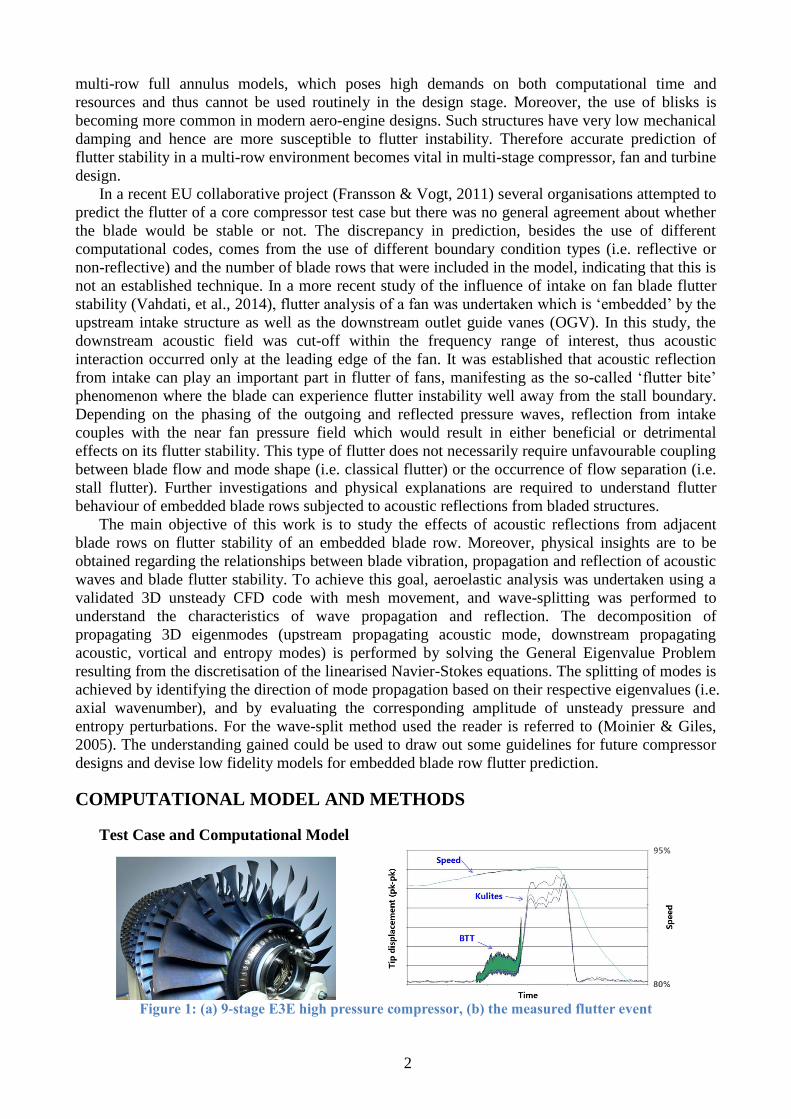
Figure 2: Steady CFD domain
The test case compressor features 9 highly loaded stages on a single spool contributing to an
overall pressure ratio of 22:1. Titanium blisks were installed on the front stages for weight saving.
The inlet guide vane (IGV) and first three stages of stator vanes (VSV) have adjustable blade
stagger angle which operate with different settings according to spool speed. All rotors are of
shroudless design (i.e. with tip clearance) and back stage stators have clearance gaps at the hub. For
CFD computation a variable area nozzle is attached behind the OGV to control the axial flow rate
as illustrated in Figure 2. Constant speed characteristics are obtained by adjusting the area of the
exit nozzle. The grids used for the blading are semi-structured, with hexahedral elements around the
aerofoil in the boundary layer region, and prismatic elements in the passage. The end-wall boundary
layers are resolved by refining the grid radially towards the hub and casing (Sayma, et al., 2000).
Typical passage mesh contains ~230,000 grid points, 39 mesh layers on the blade and 6 layers in
the tip gap. In the steady computations, the interface boundaries between rotors and stators are
modelled as mixing planes, whereas in the unsteady computations they are treated as sliding planes.
Aerodynamic Computation Methods
The computations are based on a 3D, time-accurate, viscous, finite-volume compressible flow
solver (Sayma, et al., 2000). The unsteady flow cases are computed as RANS, with the basic
assumption that the frequencies of interest are sufficiently far away from the frequencies of
turbulent flow structures. The flow variables are represented on the nodes of a generic unstructured
grid and numerical fluxes are computed along the edges of the grid. The numerical fluxes are
evaluated using Roe’s flux vector difference splitting to provide matrix artificial dissipation in a
JST (Jameson-Schmidt-Turkel) scheme. The overall solution method is implicit, with second-order
accuracy in space and time. For steady-state flow computations, the solution is advanced in pseudo-
time using local time stepping, while dual time stepping is used for unsteady computations to
preserve stability at high Courant numbers. For steady-state flow calculations, solution acceleration
techniques, such as residual smoothing and local time stepping are employed. The current
4
computations use the one-equation Spalart-Allmaras turbulence model (Spalart & Allmaras, 1992).
The parameters in Spalart-Allmaras have been adjusted based on past turbomachinery applications
to get good agreement near the stability limit; the parameters are held constant in all the present
work. The resulting CFD Code has been used over the past 20 years for flows at off-design
conditions and flutter computations with a good degree of success (Vahdati, et al., 2011) (Choi, et
al., 2013) (Dodds & Vahdati, 2014).
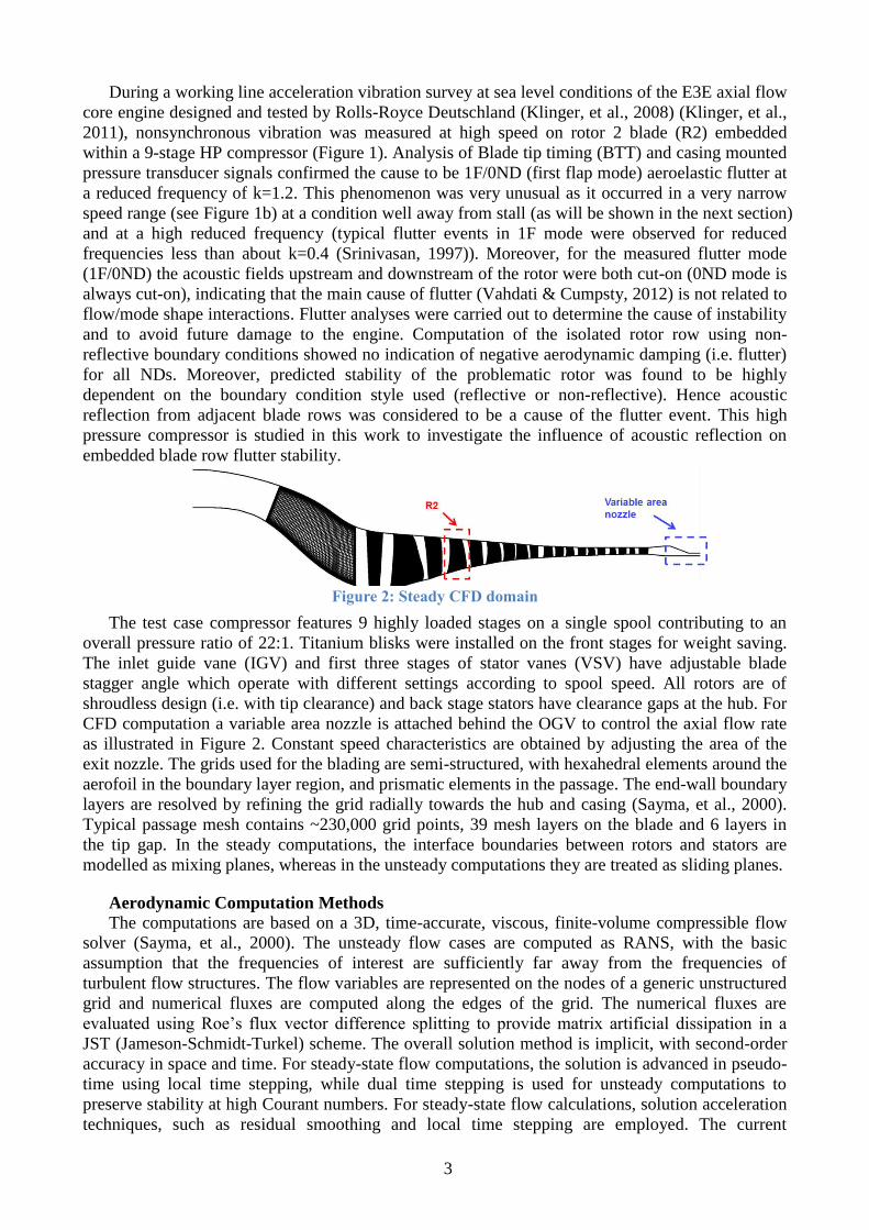
STEADY STATE COMPARISON The characteristic of the whole compressor at the speed which flutter was observed (93.1%
aerospeed) is computed by varying the exit nozzle area. A comparison of computed results with
experimental measured data is shown in Figure 3a, which shows the predicted overall pressure ratio
plotted against normalised inlet mass flow. The computed results at 93.1% aerospeed are compared
against measured data at 92.5% speed and 95% speed (due to the lack of experimental data at 93.1%
speed). The overall performance is adequately predicted. It should be mentioned that, the last point
on the measured 92.5% speed characteristic does not represent the surge boundary at this speed.
Figure 3: (a) compressor operating map, (b) radial profile comparison of total pressure with measured
92.5% speed data
In Figure 3b a comparison of computed and measured total pressure profiles at the leading edge
of front stage stators is shown. The operating points with peak adiabatic efficiency are compared in
this plot. The experimental profiles were measured with leading edge total pressure tappings at
various radial heights. In this plot, total pressure (𝑃0) is normalised by the respective radial average
values (i.e. 𝑃0̅̅ ̅). Based on the plot a good agreement between the CFD results and measured data
can be seen at the leading edge of stator 1 and stator 3. The mismatch between CFD and measured
total pressure at the root of S2 is caused by flow separation at the hub of S1 (which is migrated
radially outwards), which was not captured in the CFD computations. However, it should be noted
that the computational results shown in this paper are at 93.1% speed, and as can be seen from Fig
3b, a small increase of shaft speed (from 92.5% speed to 95% speed) reduces the intensity of this
separation by a significant amount and brings the measured data more in line with CFD results.
Nevertheless, the general trend is adequately represented by the CFD model especially at higher
span locations where the maximum blade displacement occurs (see Figure 4b), and hence
aerodynamic damping induced by the flow is dominant.
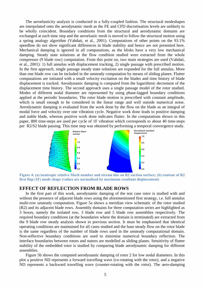
FLUTTER MODEL The rotor row of concern (rotor 2) which showed flutter instability in experimental tests has 45
blades and a hub/tip ratio around 0.7. The two adjacent stators have 38 (stator 1) and 54 (stator 2)
blades respectively. In all the flutter computations presented in this paper, the blades are excited in
first flap (1F) mode (Figure 4b) at a reduced frequency of 1.2. Results are shown for the peak
efficiency operating point. At this condition, the inlet relative Mach number at tip is around 0.8 and
the flow remains subsonic (apart from the suction peak) over the blade (see isentropic relative Mach
number contour over R2 suction surface in Figure 4a). It is also seen from Figure 4a that the flow
remains attached and the stream lines at the edge of boundary layer follow the blade stream sections.
5
The aeroelasticity analysis is conducted in a fully-coupled fashion. The structural modeshapes
are interpolated onto the aerodynamic mesh as the FE and CFD discretisation levels are unlikely to
be wholly coincident. Boundary conditions from the structural and aerodynamic domains are
exchanged at each time step and the aeroelastic mesh is moved to follow the structural motion using
a spring analogy algorithm (Vahdati, et al., 2001). Computations of other points on the 93.1%
speedline do not show significant differences in blade stability and hence are not presented here.
Mechanical damping is ignored in all computations, as the blisks have a very low mechanical
damping. Steady state solutions at the flow condition studied were extracted from the whole
compressor (9 blade row) computation. From this point on, two main strategies are used (Vahdati,
et al., 2001): 1) full annulus with displacement tracking, 2) single passage with prescribed motion.
In the first approach, single passage steady state solutions are expanded for the full annulus. More
than one blade row can be included in the unsteady computation by means of sliding planes. Flutter
computations are initiated with a small velocity excitation on the blades and time history of blade
displacement is tracked. Aerodynamic damping is computed from the logarithmic decrement of the
displacement time history. The second approach uses a single passage model of the rotor studied.
Modes of different nodal diameter are represented by using phase-lagged boundary conditions
applied at the periodic boundaries. The rotor blade motion is prescribed with constant amplitude,
which is small enough to be considered in the linear range and well outside numerical noise.
Aerodynamic damping is evaluated from the work done by the flow on the blade as an integral of
modal force and velocity over one vibration cycle. Negative work done leads to positive damping
and stable blade, whereas positive work done indicates flutter. In the computations shown in this
paper, 800 time-steps are used per cycle of 1F vibration which corresponds to about 40 time-steps
per R2/S2 blade passing. This time step was obtained by performing a temporal convergence study.
Figure 4: (a) isentropic relative Mach number and stream line on R2 suction surface; (b) contour of R2
first flap (1F) mode shape (values are normalised by maximum resultant displacement)
EFFECT OF REFLECTION FROM BLADE ROWS In the first part of this work, aerodynamic damping of the test case rotor is studied with and
without the presence of adjacent blade rows using the aforementioned first strategy, i.e. full annulus
multi-row unsteady computation. Figure 5a shows a meridian view schematic of the rotor studied
(R2) and its adjacent blade rows. Assembly domains for three computation series are highlighted as
3 boxes, namely the isolated row, 3 blade row and 5 blade row assemblies respectively. The
required boundary conditions (at the boundaries where the domain is terminated) are extracted from
the 9 blade row steady analysis shown in previous section. It must be emphasised that identical
operating conditions are maintained for all cases studied and the base steady flow on the rotor blade
is the same regardless of the number of blade rows used in the unsteady computational domain.
Non-reflective boundary conditions are used to minimise numerical boundary reflection. The
interface boundaries between rotors and stators are modelled as sliding planes. Sensitivity of flutter
stability of the embedded rotor is studied by comparing blade aerodynamic damping for different
assemblies.
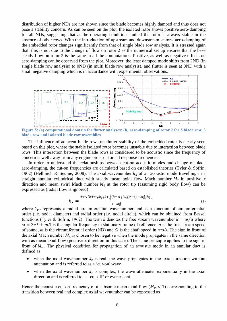
Figure 5b shows the computed aerodynamic damping of rotor 2 for low nodal diameters. In this
plot a positive ND represents a forward travelling wave (co-rotating with the rotor), and a negative
ND represents a backward travelling wave (counter-rotating with the rotor). The aero-damping
6
distribution of higher NDs are not shown since the blade becomes highly damped and thus does not
pose a stability concern. As can be seen on the plot, the isolated rotor shows positive aero-damping
for all NDs, suggesting that at the operating condition studied the rotor is always stable in the
absence of other rows. With the introduction of upstream and downstream stators, aero-damping of
the embedded rotor changes significantly from that of single blade row analysis. It is stressed again
that, this is not due to the change of flow on rotor 2 as the numerical set up ensures that the base
steady flow on rotor 2 is the same in all the computations. Positive, as well as negative effects on
aero-damping can be observed from the plot. Moreover, the least damped mode shifts from 2ND (in
single blade row analysis) to 0ND (in multi blade row analysis), and flutter is seen at 0ND with a
small negative damping which is in accordance with experimental observations.
Figure 5: (a) computational domain for flutter analyses; (b) aero-damping of rotor 2 for 5 blade row, 3
blade row and isolated blade row assemblies
The influence of adjacent blade rows on flutter stability of the embedded rotor is clearly seen
based on this plot, where the stable isolated rotor becomes unstable due to interaction between blade
rows. This interaction between the blade rows is considered to be acoustic since the frequency of
concern is well away from any engine order or forced response frequencies.
In order to understand the relationships between cut-on acoustic modes and change of blade
aero-damping, the cut-on frequencies are calculated based on established theories (Tyler & Sofrin,
1962) (Hellmich & Seume, 2008). The axial wavenumber 𝑘𝑥 of an acoustic mode travelling in a
straight annular cylindrical duct with steady mean axial flow Mach number 𝑀𝑥 in positive x
direction and mean swirl Mach number 𝑀𝜃 at the rotor tip (assuming rigid body flow) can be
expressed as (radial flow is ignored)
𝑘𝑥 =±𝑀𝑥(𝑘±𝑀𝜃𝑘𝑟𝜃)+√(𝑘±𝑀𝜃𝑘𝑟𝜃)2−(1−𝑀𝑥
2)𝑘𝑟𝜃2
1−𝑀𝑥2 (1)
where 𝑘𝑟𝜃 represents a radial-circumferential wavenumber and is a function of circumferential
order (i.e. nodal diameter) and radial order (i.e. nodal circle), which can be obtained from Bessel
functions (Tyler & Sofrin, 1962). The term k denotes the free stream wavenumber 𝑘 = 𝜔 𝑎⁄ where
𝜔 = 2𝜋𝑓 + 𝑚𝛺 is the angular frequency in stationary frame of reference, a is the free stream speed
of sound, m is the circumferential order (ND) and Ω is the shaft speed in rad/s. The sign in front of
the axial Mach number 𝑀𝑥 is chosen to be negative when the mode propagates in the same direction
with as mean axial flow (positive x direction in this case). The same principle applies to the sign in
front of 𝑀𝜃 . The physical condition for propagation of an acoustic mode in an annular duct is
defined as
when the axial wavenumber kx is real, the wave propagates in the axial direction without
attenuation and is referred to as a ‘cut-on’ wave
when the axial wavenumber kx is complex, the wave attenuates exponentially in the axial
direction and is referred to as ‘cut-off’ or evanescent
Hence the acoustic cut-on frequency of a subsonic mean axial flow (𝑀𝑥 < 1) corresponding to the
transition between real and complex axial wavenumber can be expressed as
7
𝜔𝑐𝑢𝑡−𝑜𝑛 = a𝑘𝑟𝜃(√1 − 𝑀𝑥2 ∓ 𝑀𝜃) (2)
The above equations have been obtained by assuming negligible radial flow (or radial variation of
axial and swirl components) and a uniform duct radius.
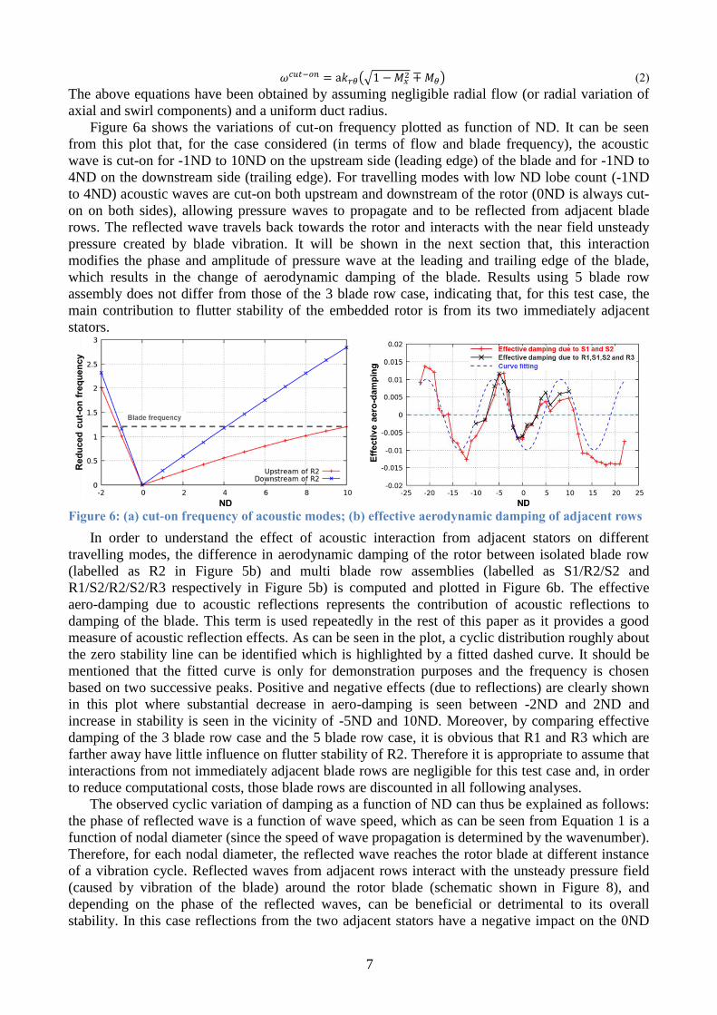
Figure 6a shows the variations of cut-on frequency plotted as function of ND. It can be seen
from this plot that, for the case considered (in terms of flow and blade frequency), the acoustic
wave is cut-on for -1ND to 10ND on the upstream side (leading edge) of the blade and for -1ND to
4ND on the downstream side (trailing edge). For travelling modes with low ND lobe count (-1ND
to 4ND) acoustic waves are cut-on both upstream and downstream of the rotor (0ND is always cut-
on on both sides), allowing pressure waves to propagate and to be reflected from adjacent blade
rows. The reflected wave travels back towards the rotor and interacts with the near field unsteady
pressure created by blade vibration. It will be shown in the next section that, this interaction
modifies the phase and amplitude of pressure wave at the leading and trailing edge of the blade,
which results in the change of aerodynamic damping of the blade. Results using 5 blade row
assembly does not differ from those of the 3 blade row case, indicating that, for this test case, the
main contribution to flutter stability of the embedded rotor is from its two immediately adjacent
stators.
Figure 6: (a) cut-on frequency of acoustic modes; (b) effective aerodynamic damping of adjacent rows
In order to understand the effect of acoustic interaction from adjacent stators on different
travelling modes, the difference in aerodynamic damping of the rotor between isolated blade row
(labelled as R2 in Figure 5b) and multi blade row assemblies (labelled as S1/R2/S2 and
R1/S2/R2/S2/R3 respectively in Figure 5b) is computed and plotted in Figure 6b. The effective
aero-damping due to acoustic reflections represents the contribution of acoustic reflections to
damping of the blade. This term is used repeatedly in the rest of this paper as it provides a good
measure of acoustic reflection effects. As can be seen in the plot, a cyclic distribution roughly about
the zero stability line can be identified which is highlighted by a fitted dashed curve. It should be
mentioned that the fitted curve is only for demonstration purposes and the frequency is chosen
based on two successive peaks. Positive and negative effects (due to reflections) are clearly shown
in this plot where substantial decrease in aero-damping is seen between -2ND and 2ND and
increase in stability is seen in the vicinity of -5ND and 10ND. Moreover, by comparing effective
damping of the 3 blade row case and the 5 blade row case, it is obvious that R1 and R3 which are
farther away have little influence on flutter stability of R2. Therefore it is appropriate to assume that
interactions from not immediately adjacent blade rows are negligible for this test case and, in order
to reduce computational costs, those blade rows are discounted in all following analyses.
The observed cyclic variation of damping as a function of ND can thus be explained as follows:
the phase of reflected wave is a function of wave speed, which as can be seen from Equation 1 is a
function of nodal diameter (since the speed of wave propagation is determined by the wavenumber).
Therefore, for each nodal diameter, the reflected wave reaches the rotor blade at different instance
of a vibration cycle. Reflected waves from adjacent rows interact with the unsteady pressure field
(caused by vibration of the blade) around the rotor blade (schematic shown in Figure 8), and
depending on the phase of the reflected waves, can be beneficial or detrimental to its overall
stability. In this case reflections from the two adjacent stators have a negative impact on the 0ND
8
mode of R2, which is responsible for the flutter event observed in the experiment and predicted in
Figure 5b.
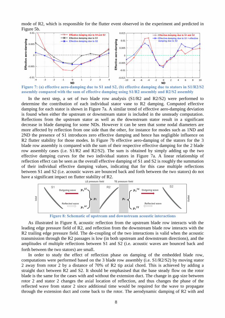
Figure 7: (a) effective aero-damping due to S1 and S2, (b) effective damping due to stators in S1/R2/S2
assembly compared with the sum of effective damping using S1/R2 assembly and R2/S2 assembly
In the next step, a set of two blade row analysis (S1/R2 and R2/S2) were performed to
determine the contribution of each individual stator vane to R2 damping. Computed effective
damping for each stator is shown in Figure 7a. A similar trend of effective aero-damping deviation
is found when either the upstream or downstream stator is included in the unsteady computation.
Reflections from the upstream stator as well as the downstream stator result in a significant
decrease in blade damping for some NDs. However it can be seen that some nodal diameters are
more affected by reflection from one side than the other, for instance for modes such as 1ND and
2ND the presence of S1 introduces zero effective damping and hence has negligible influence on
R2 flutter stability for those modes. In Figure 7b effective aero-damping of the stators for the 3
blade row assembly is compared with the sum of their respective effective damping for the 2 blade
row assembly cases (i.e. S1/R2 and R2/S2). The sum is obtained by simply adding up the two
effective damping curves for the two individual stators in Figure 7a. A linear relationship of
reflection effect can be seen as the overall effective damping of S1 and S2 is roughly the summation
of their individual effective damping values, indicating that for this case multiple reflections
between S1 and S2 (i.e. acoustic waves are bounced back and forth between the two stators) do not
have a significant impact on flutter stability of R2.
Figure 8: Schematic of upstream and downstream acoustic interactions
As illustrated in Figure 8, acoustic reflection from the upstream blade row interacts with the
leading edge pressure field of R2, and reflection from the downstream blade row interacts with the
R2 trailing edge pressure field. The de-coupling of the two interactions is valid when the acoustic
transmission through the R2 passages is low (in both upstream and downstream directions), and the
amplitudes of multiple reflections between S1 and S2 (i.e. acoustic waves are bounced back and
forth between the two stators) are small. In order to study the effect of reflection phase on damping of the embedded blade row,
computations were performed based on the 3 blade row assembly (i.e. S1/R2/S2) by moving stator
2 away from rotor 2 by a distance of 70% of R2 tip axial chord. This is achieved by adding a
straight duct between R2 and S2. It should be emphasised that the base steady flow on the rotor
blade is the same for the cases with and without the extension duct. The change in gap size between
rotor 2 and stator 2 changes the axial location of reflection, and thus changes the phase of the
reflected wave from stator 2 since additional time would be required for the wave to propagate
through the extension duct and come back to the rotor. The aerodynamic damping of R2 with and
9
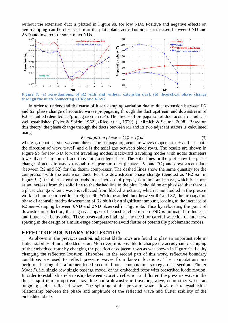
without the extension duct is plotted in Figure 9a, for low NDs. Positive and negative effects on
aero-damping can be observed from the plot; blade aero-damping is increased between 0ND and
2ND and lowered for some other NDs.
Figure 9: (a) aero-damping of R2 with and without extension duct, (b) theoretical phase change
through the ducts connecting S1/R2 and R2/S2
In order to understand the cause of blade damping variation due to duct extension between R2
and S2, phase change of acoustic waves propagating through the duct upstream and downstream of
R2 is studied (denoted as ‘propagation phase’). The theory of propagation of duct acoustic modes is
well established (Tyler & Sofrin, 1962), (Rice, et al., 1979), (Hellmich & Seume, 2008). Based on
this theory, the phase change through the ducts between R2 and its two adjacent stators is calculated
using 𝑃𝑟𝑜𝑝𝑎𝑔𝑎𝑡𝑖𝑜𝑛 𝑝ℎ𝑎𝑠𝑒 = (𝑘𝑥
+ + 𝑘𝑥−)𝑑 (3)
where kx denotes axial wavenumber of the propagating acoustic waves (superscript + and – denote
the direction of wave travel) and d is the axial gap between blade rows. The results are shown in
Figure 9b for low ND forward travelling modes. Backward travelling modes with nodal diameters
lower than -1 are cut-off and thus not considered here. The solid lines in the plot show the phase
change of acoustic waves through the upstream duct (between S1 and R2) and downstream duct
(between R2 and S2) for the datum compressor. The dashed lines show the same quantity for the
compressor with the extension duct. For the downstream phase change (denoted as ‘R2-S2’ in
Figure 9b), the duct extension leads to an increase of propagation time and phase, which is shown
as an increase from the solid line to the dashed line in the plot. It should be emphasised that there is
a phase change when a wave is reflected from bladed structures, which is not studied in the present
work and not accounted for in Figure 9b. With the added duct between R2 and S2, the propagation
phase of acoustic modes downstream of R2 shifts by a significant amount, leading to the increase of
R2 aero-damping between 0ND and 2ND observed in Figure 9a. Thus by relocating the point of
downstream reflection, the negative impact of acoustic reflection on 0ND is mitigated in this case
and flutter can be avoided. These observations highlight the need for careful selection of inter-row
spacing in the design of a multi-stage compressor to avoid flutter of potentially problematic modes.
EFFECT OF BOUNDARY REFLECTION As shown in the previous section, adjacent blade rows are found to play an important role in
flutter stability of an embedded rotor. Moreover, it is possible to change the aerodynamic damping
of the embedded rotor by changing the position of adjacent rows as was shown in Figure 9a, i.e. by
changing the reflection location. Therefore, in the second part of this work, reflective boundary
conditions are used to reflect pressure waves from known locations. The computations are
performed using the aforementioned second flutter computation strategy (see section ‘Flutter
Model’), i.e. single row single passage model of the embedded rotor with prescribed blade motion.
In order to establish a relationship between acoustic reflection and flutter, the pressure wave in the
duct is split into an upstream travelling and a downstream travelling wave, or in other words an
outgoing and a reflected wave. The splitting of the pressure wave allows one to establish a
relationship between the phase and amplitude of the reflected wave and flutter stability of the
embedded blade.
10
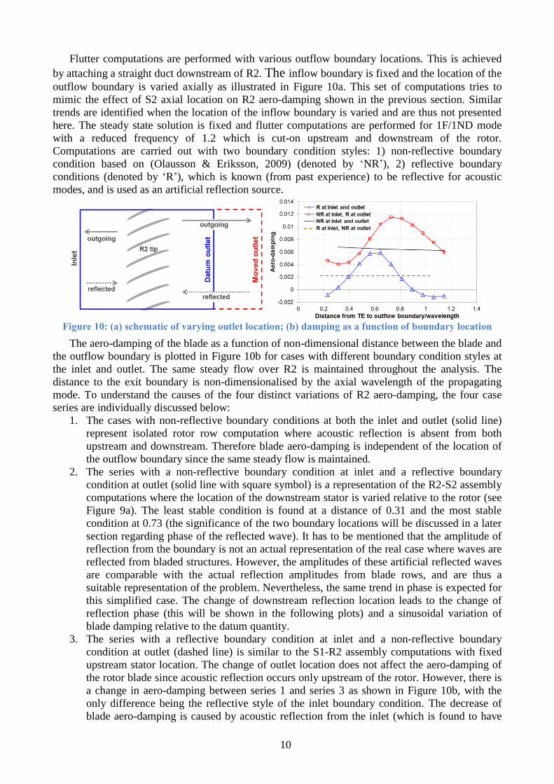
Flutter computations are performed with various outflow boundary locations. This is achieved
by attaching a straight duct downstream of R2. The inflow boundary is fixed and the location of the
outflow boundary is varied axially as illustrated in Figure 10a. This set of computations tries to
mimic the effect of S2 axial location on R2 aero-damping shown in the previous section. Similar
trends are identified when the location of the inflow boundary is varied and are thus not presented
here. The steady state solution is fixed and flutter computations are performed for 1F/1ND mode
with a reduced frequency of 1.2 which is cut-on upstream and downstream of the rotor.
Computations are carried out with two boundary condition styles: 1) non-reflective boundary
condition based on (Olausson & Eriksson, 2009) (denoted by ‘NR’), 2) reflective boundary
conditions (denoted by ‘R’), which is known (from past experience) to be reflective for acoustic
modes, and is used as an artificial reflection source.
Figure 10: (a) schematic of varying outlet location; (b) damping as a function of boundary location
The aero-damping of the blade as a function of non-dimensional distance between the blade and
the outflow boundary is plotted in Figure 10b for cases with different boundary condition styles at
the inlet and outlet. The same steady flow over R2 is maintained throughout the analysis. The
distance to the exit boundary is non-dimensionalised by the axial wavelength of the propagating
mode. To understand the causes of the four distinct variations of R2 aero-damping, the four case
series are individually discussed below:
1. The cases with non-reflective boundary conditions at both the inlet and outlet (solid line)
represent isolated rotor row computation where acoustic reflection is absent from both
upstream and downstream. Therefore blade aero-damping is independent of the location of
the outflow boundary since the same steady flow is maintained.
2. The series with a non-reflective boundary condition at inlet and a reflective boundary
condition at outlet (solid line with square symbol) is a representation of the R2-S2 assembly
computations where the location of the downstream stator is varied relative to the rotor (see
Figure 9a). The least stable condition is found at a distance of 0.31 and the most stable
condition at 0.73 (the significance of the two boundary locations will be discussed in a later
section regarding phase of the reflected wave). It has to be mentioned that the amplitude of
reflection from the boundary is not an actual representation of the real case where waves are
reflected from bladed structures. However, the amplitudes of these artificial reflected waves
are comparable with the actual reflection amplitudes from blade rows, and are thus a
suitable representation of the problem. Nevertheless, the same trend in phase is expected for
this simplified case. The change of downstream reflection location leads to the change of
reflection phase (this will be shown in the following plots) and a sinusoidal variation of
blade damping relative to the datum quantity.
3. The series with a reflective boundary condition at inlet and a non-reflective boundary
condition at outlet (dashed line) is similar to the S1-R2 assembly computations with fixed
upstream stator location. The change of outlet location does not affect the aero-damping of
the rotor blade since acoustic reflection occurs only upstream of the rotor. However, there is
a change in aero-damping between series 1 and series 3 as shown in Figure 10b, with the
only difference being the reflective style of the inlet boundary condition. The decrease of
blade aero-damping is caused by acoustic reflection from the inlet (which is found to have
11
destabilising effect for this mode in this set up due to its location), and is thus identical for
any location of the outlet.
4. The series with reflective boundary conditions at both the inlet and outlet (solid line with
triangular symbol) is a representation of R2 in an embedded setup (i.e. S1-R2-S2 assembly)
where acoustic reflection comes from upstream as well as downstream. Sinusoidal blade
damping variation similar to series 2 can be seen as a result of the change of downstream
reflection location. The overall drop in blade aero-damping (i.e. the drop of mean value of
the sinusoidal damping variation from series 2 to series 4 as shown in Figure 10b) on the
other hand is due to the presence of upstream reflection as discussed above.
It is clear from the plot that acoustic reflection has a major influence on flutter stability of the
blade, and a stable blade can become unstable. It can also be seen that the variation of blade
damping repeats itself with a cycle of around 1 wavelength during which the phase of wave
experiences a 360° change, indicating a relationship between blade damping and the phase of
reflected waves.
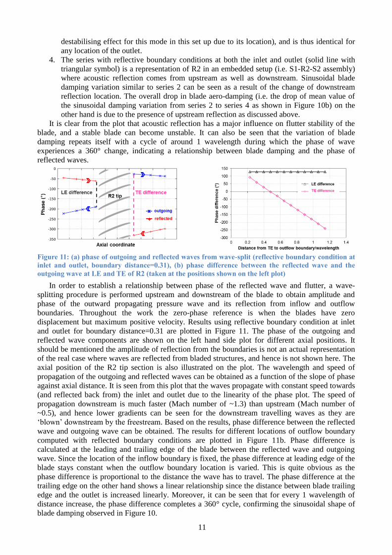
Figure 11: (a) phase of outgoing and reflected waves from wave-split (reflective boundary condition at
inlet and outlet, boundary distance=0.31), (b) phase difference between the reflected wave and the
outgoing wave at LE and TE of R2 (taken at the positions shown on the left plot)
In order to establish a relationship between phase of the reflected wave and flutter, a wave-
splitting procedure is performed upstream and downstream of the blade to obtain amplitude and
phase of the outward propagating pressure wave and its reflection from inflow and outflow
boundaries. Throughout the work the zero-phase reference is when the blades have zero
displacement but maximum positive velocity. Results using reflective boundary condition at inlet
and outlet for boundary distance=0.31 are plotted in Figure 11. The phase of the outgoing and
reflected wave components are shown on the left hand side plot for different axial positions. It
should be mentioned the amplitude of reflection from the boundaries is not an actual representation
of the real case where waves are reflected from bladed structures, and hence is not shown here. The
axial position of the R2 tip section is also illustrated on the plot. The wavelength and speed of
propagation of the outgoing and reflected waves can be obtained as a function of the slope of phase
against axial distance. It is seen from this plot that the waves propagate with constant speed towards
(and reflected back from) the inlet and outlet due to the linearity of the phase plot. The speed of
propagation downstream is much faster (Mach number of ~1.3) than upstream (Mach number of
~0.5), and hence lower gradients can be seen for the downstream travelling waves as they are
‘blown’ downstream by the freestream. Based on the results, phase difference between the reflected
wave and outgoing wave can be obtained. The results for different locations of outflow boundary
computed with reflected boundary conditions are plotted in Figure 11b. Phase difference is
calculated at the leading and trailing edge of the blade between the reflected wave and outgoing
wave. Since the location of the inflow boundary is fixed, the phase difference at leading edge of the
blade stays constant when the outflow boundary location is varied. This is quite obvious as the
phase difference is proportional to the distance the wave has to travel. The phase difference at the
trailing edge on the other hand shows a linear relationship since the distance between blade trailing
edge and the outlet is increased linearly. Moreover, it can be seen that for every 1 wavelength of
distance increase, the phase difference completes a 360° cycle, confirming the sinusoidal shape of
blade damping observed in Figure 10.
12
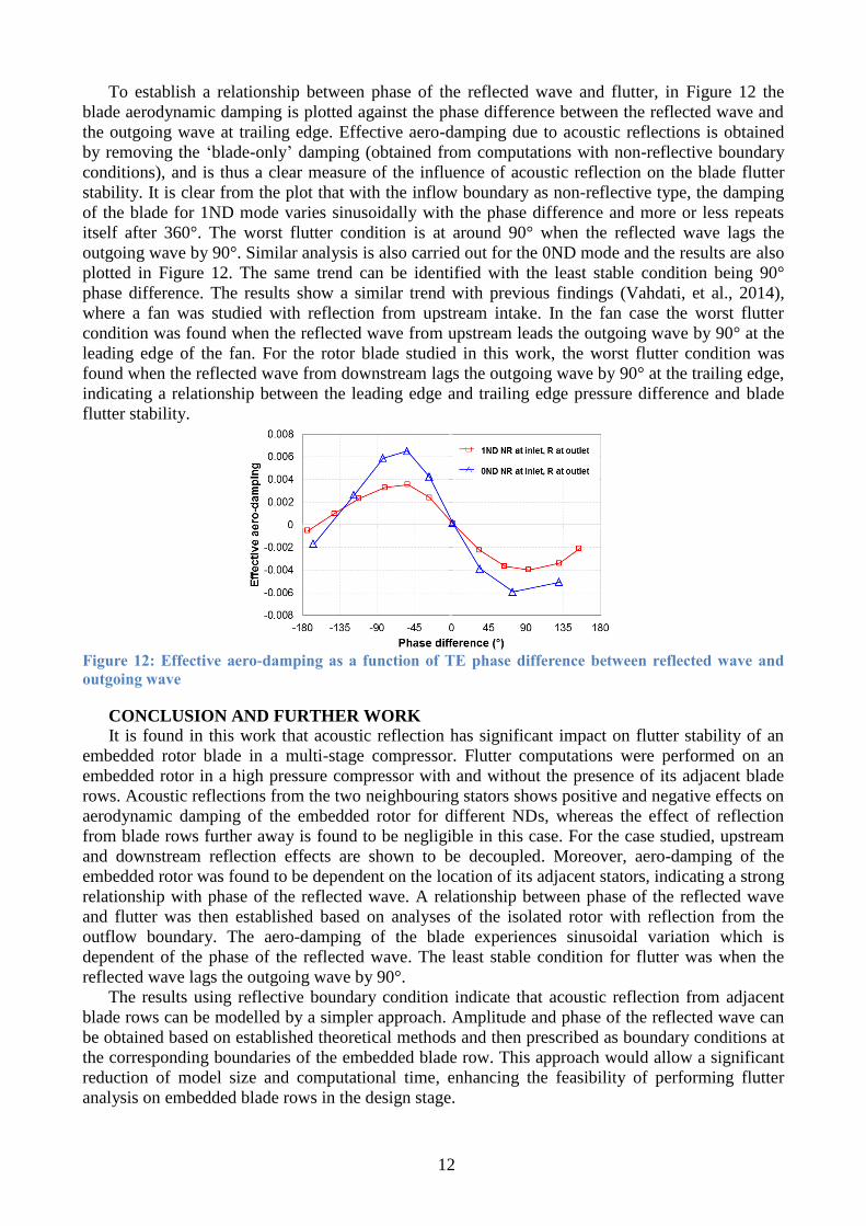
To establish a relationship between phase of the reflected wave and flutter, in Figure 12 the
blade aerodynamic damping is plotted against the phase difference between the reflected wave and
the outgoing wave at trailing edge. Effective aero-damping due to acoustic reflections is obtained
by removing the ‘blade-only’ damping (obtained from computations with non-reflective boundary
conditions), and is thus a clear measure of the influence of acoustic reflection on the blade flutter
stability. It is clear from the plot that with the inflow boundary as non-reflective type, the damping
of the blade for 1ND mode varies sinusoidally with the phase difference and more or less repeats
itself after 360°. The worst flutter condition is at around 90° when the reflected wave lags the
outgoing wave by 90°. Similar analysis is also carried out for the 0ND mode and the results are also
plotted in Figure 12. The same trend can be identified with the least stable condition being 90°
phase difference. The results show a similar trend with previous findings (Vahdati, et al., 2014),
where a fan was studied with reflection from upstream intake. In the fan case the worst flutter
condition was found when the reflected wave from upstream leads the outgoing wave by 90° at the
leading edge of the fan. For the rotor blade studied in this work, the worst flutter condition was
found when the reflected wave from downstream lags the outgoing wave by 90° at the trailing edge,
indicating a relationship between the leading edge and trailing edge pressure difference and blade
flutter stability.
Figure 12: Effective aero-damping as a function of TE phase difference between reflected wave and
outgoing wave
CONCLUSION AND FURTHER WORK
It is found in this work that acoustic reflection has significant impact on flutter stability of an
embedded rotor blade in a multi-stage compressor. Flutter computations were performed on an
embedded rotor in a high pressure compressor with and without the presence of its adjacent blade
rows. Acoustic reflections from the two neighbouring stators shows positive and negative effects on
aerodynamic damping of the embedded rotor for different NDs, whereas the effect of reflection
from blade rows further away is found to be negligible in this case. For the case studied, upstream
and downstream reflection effects are shown to be decoupled. Moreover, aero-damping of the
embedded rotor was found to be dependent on the location of its adjacent stators, indicating a strong
relationship with phase of the reflected wave. A relationship between phase of the reflected wave
and flutter was then established based on analyses of the isolated rotor with reflection from the
outflow boundary. The aero-damping of the blade experiences sinusoidal variation which is
dependent of the phase of the reflected wave. The least stable condition for flutter was when the
reflected wave lags the outgoing wave by 90°.
The results using reflective boundary condition indicate that acoustic reflection from adjacent
blade rows can be modelled by a simpler approach. Amplitude and phase of the reflected wave can
be obtained based on established theoretical methods and then prescribed as boundary conditions at
the corresponding boundaries of the embedded blade row. This approach would allow a significant
reduction of model size and computational time, enhancing the feasibility of performing flutter
analysis on embedded blade rows in the design stage.
13
ACKNOWLEDGEMENTS
The experimental results presented are part of the completed research project “Validation Core
Engine” (grant no. 20T0305) which was funded by the German BMWi and Rolls-Royce
Deutschland Ltd. & Co KG. Rolls-Royce Deutschland’s permission to publish this work is greatly
acknowledged. The authors gratefully acknowledge the contribution of their colleagues B. Mueck
and J. Green at Rolls-Royce plc.
REFERENCES
Choi, M., Smith, N. H. S. & Vahdati, M., 2013. Validation of Numerical Simulation for Rotating Stall in
a Transonic Fan. J. Turbomach., 135(2), p. 021004.
Dodds, J. & Vahdati, M., 2014. Rotating stall observations in a high speed compressor part 2: numerical
study. J. Turbomach., 137(5), p. 051003.
Doi, H. & Alonso, J., 2002. Fluid-Structure Coupled Aeroelastic Computations for Transonic Flows in
Turbomachinery. The Netherlands, ASME Turbo Expo 2002.
Fransson, T. & Vogt, D., 2011. FUTURE Flutter-Free Turbomachinery Blades, Madrid: Aero Days
2011.
He, L., 1994. Integration of 2D fluid-structure coupled system for calculations of turbomachinery
aerodynamic instabilities. Int. J. of Comp Fluid Dynamics, 3(4), pp. 217-231.
Hellmich, B. & Seume, J. R., 2008. Causes of Acoustic Resonance in a High-Speed Axial Compressor.
Journal of Turbomach., 130(3), p. 031003.
Hsu, K., Hoyniak, D. & Anand, M. S., 2012. Full-Annulus Multi-Row Flutter Analyses. Copenhagen,
Denmark, ASME Turbo Expo 2012.
Klinger, H., Bake, S., Vogt, H. & Knieschke, D., 2011. Altitude Testing of the E3E Core Engine.
Vancouver, Canada, ASME Turbo Expo 2011.
Klinger, H., Lazik, W. & Wunderlich, T., 2008. The Engine 3E Core Engine. Berlin, Germany, ASME
Turbo Expo 2008.
Li, H. D. & He, L., 2005. Blade Aerodynamic Damping Variation With RotorStator Gap: A
Computational Study Using Single-Passage Approach. ASME J. Turbomach., 127(3), pp. 573-579.
McBean, I., Hourigan, K. & Thompson, M., 2005. Prediction of Flutter of Turbine Blades in a Transonic
Annular Cascade. J. of Fluids Eng., 127(4), pp. 1053-1058.
Moinier, P. & Giles, M. B., 2005. Eigenmode Analysis for Turbomachinery Applications. AIAA J. of
Prop. and Power, 21(6), pp. 973-978.
Olausson, M. & Eriksson, L. E., 2009. An Absorbing Inlet Buffer Layer for Rotor Wake/Stator Time
Domain Computations. Florida, USA, Proceedings of ASME Turbo Expo 2009.
Rice, E., Heidmann, M. & Sofrin, T., 1979. Modal propagation angles in a cylindrical duct with flow
and their relation to sound radiation. New Orleans, LA, USA, Aerospace Sci. Meeting 17th.
Sayma, A. I., Vahdati, M., Sbardella, L. & Imregun, M., 2000. Modeling of three-dimensional viscous
compressible turbomachinery flows using unstructured hybrid grids. AIAA Journal, 38(6), pp. 945-954.
Schoenenborn, H. & Ashcroft, G., 2014. Comparison of non-linear and linearized CFD analysis of the
stator-rotor interaction of a compressor stage. Dusseldorf, Germany, Preceedings of ASME Turbo Expo
2014.
Spalart, P. R. & Allmaras, S. R., 1992. A one-equation turbulence model for aerodynamic flows. AIAA-
92-0439.
Srinivasan, A. V., 1997. Flutter and resonant vibration characteristics of engine blades. J. of Eng. for Gas
Turbines and Power, 119(4), pp. 742-775.
Tyler, J. M. & Sofrin, T. G., 1962. Axial flow compressor noise studies. SAE Transactions, Volume 70,
pp. 309-332.
Vahdati, M. & Cumpsty, N. A., 2012. The mechanism of aeroelastic instability in transonic fans. Tokyo,
Japan, ISUAAAT13.
Vahdati, M. & Imergun, M., 1996. A Nonlinear Aeroelasticity Analysis of a Fan Blade Using
Unstructured Dynamic Meshes. Proc. Inst. Mech. Eng., Part C: J. Mech. Eng. Sci., 210(6), p. 549–564.
Vahdati, M., Sayma, A. I., Marshall, J. G. & Imregun, M., 2001. Mechanisms and prediction methods for
fan blade stall flutter. AIAA Journal of Propulsion and Power, 17(5), pp. 1100-1108.
Vahdati, M., Simpson, G. & Imregun, M., 2011. Mechanisms for wide-chord fan blade flutter. ASME J.
of Turbomach., 133(4), p. 041029.
Vahdati, M., Smith, N. & Zhao, F., 2014. Influence of intake on fan blade flutter. Dusseldorf, Germany,
ASME Turbo Expo 2014.