Embed Size (px)
Citation preview
Initial Position Orientation Tracking System (IPOTS)
Group Members:
Keiichi McGuire Henry Pham
Marc Takamori Scott Spiro

Outline
Problem Description Approaches How It Works Test & Results Current Status Q&A
Problem Description
Design and implement a portable position and orientation tracking system for a hand-held device (such as a camcorder)
Records the position and orientation of the device as it is carried by a person.
Transfer data via USB or external storage media, to a personal computer for analysis of the device’s motion.
Approaches
Method 1: Electromagnetic Position Tracking System
Springs & Electricity Magnetic Pulse Measurements
Method 2: Single Purpose IC
Accelerometers Gyroscopes Analog Compass
Analysis of both approaches
E&M Position Tracking System Sensitive to local magnetic fields Lack of background in advanced physics Costly
Single Purpose IC Chips Feasible approach to solve problem Easily attainable parts
How it Works
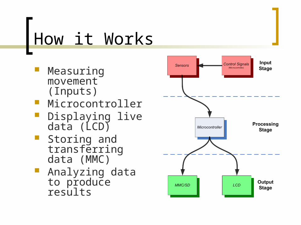
Measuring movement (Inputs)
Microcontroller Displaying live data
(LCD) Storing and
transferring data (MMC)
Analyzing data to produce results
How It Works (Measurements)
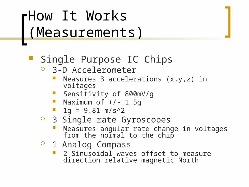
Single Purpose IC Chips 3-D Accelerometer
Measures 3 accelerations (x,y,z) in voltages Sensitivity of 800mV/g Maximum of +/- 1.5g 1g = 9.81 m/s^2
3 Single rate Gyroscopes Measures angular rate change in voltages from the
normal to the chip 1 Analog Compass
2 Sinusoidal waves offset to measure direction relative magnetic North
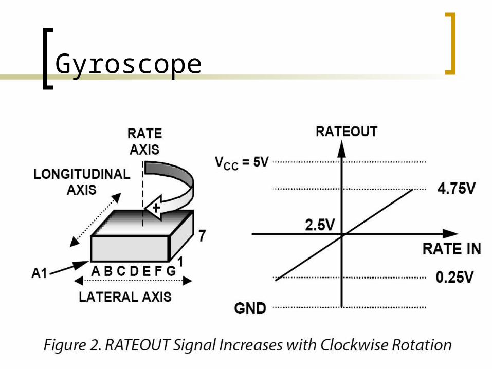
Gyroscope
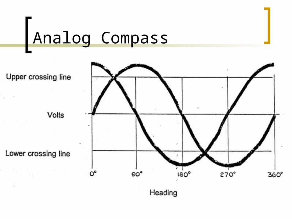
Analog Compass
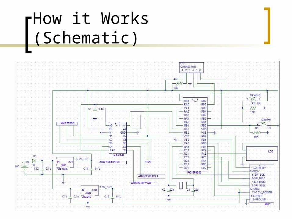
How it Works (Schematic)
How it works (Microcontroller)
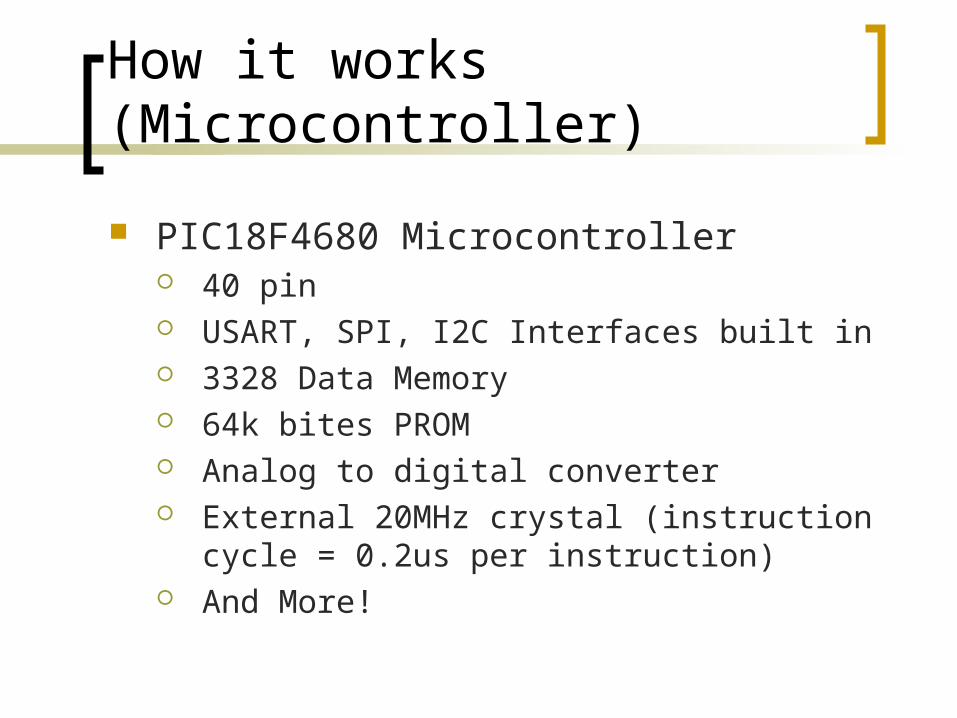
PIC18F4680 Microcontroller 40 pin USART, SPI, I2C Interfaces built in 3328 Data Memory 64k bites PROM Analog to digital converter External 20MHz crystal (instruction cycle = 0.2us
per instruction) And More!
How it Works (Firmware)
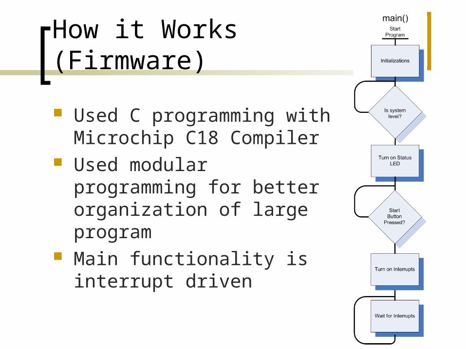
Used C programming with Microchip C18 Compiler
Used modular programming for better organization of large program
Main functionality is interrupt driven
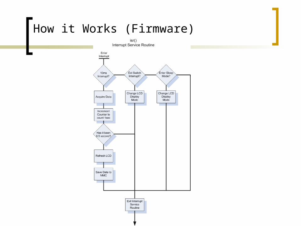
How it Works (Firmware)
How it Works (LCD)
Asynchronous serial interface Microcontroller will send ASCII
characters through USART 16 x 2 characters 19200 baud rate
How it Works (Sensor Interface)
Total of 8 different sensors multiplexed into the analog to digital converter
Microcontroller steps through all select line combinations to acquire all data (appx 20us between each sample)
Delay is put in software to compensate for the time taken to switch inputs (appx 2us).
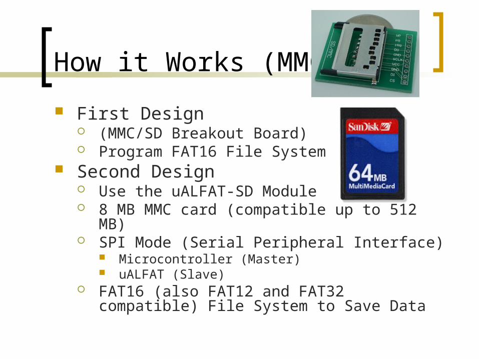
How it Works (MMC)
First Design (MMC/SD Breakout Board) Program FAT16 File System
Second Design Use the uALFAT-SD Module 8 MB MMC card (compatible up to 512 MB) SPI Mode (Serial Peripheral Interface)
Microcontroller (Master) uALFAT (Slave)
FAT16 (also FAT12 and FAT32 compatible) File System to Save Data
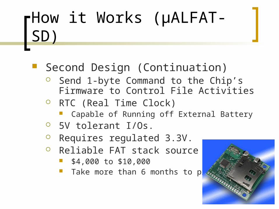
How it Works (μALFAT-SD)
Second Design (Continuation) Send 1-byte Command to the Chip’s Firmware
to Control File Activities RTC (Real Time Clock)
Capable of Running off External Battery 5V tolerant I/Os. Requires regulated 3.3V. Reliable FAT stack source code
$4,000 to $10,000 Take more than 6 months to program
How it Works (Sleep/Low Voltage Detect Mode)
Both Functions use built in features of the PIC. LVD mode works like interrupt
Software programmable to desired voltage Trigger interrupt
Sleep Software programmable – two step sleep Turns off all oscillators Goes to sleep after 2minutes of no use
Combined At a lvd, a sleep timer is initiated to automatically put
device to sleep in 2 minutes
How it Works (Compiling Data)
Matlab 7.0 used as development tool to create an executable file which will convert raw data saved on MMC/SD develop data
Uses Rotation Transformation Matrices Outputs tabulated data in a new text file in
meters and angles Account for sensitivity and errors using
Kalman Filter
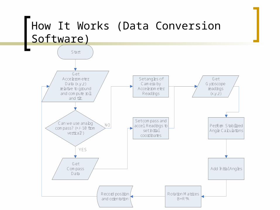
How It Works (Data Conversion Software)
Get Accelerometer
Data (x,y,z) relative to ground and compute roll
and tilt.
Can we use analog compass? (+/- 10 from
vertical?)
Set angles of Camera by
Accelerometer Readings
NO
YES
Get Compass
Data
Set compass and accel. Readings to
set initial coordinates
Get Gyroscope readings
(x,y,z)
Perform Stabilized Angle Calculations
Add Initial Angles
Rotation MatricesB=R*A
Record position and orientation
Start
ADC / LCD Test & Implementation
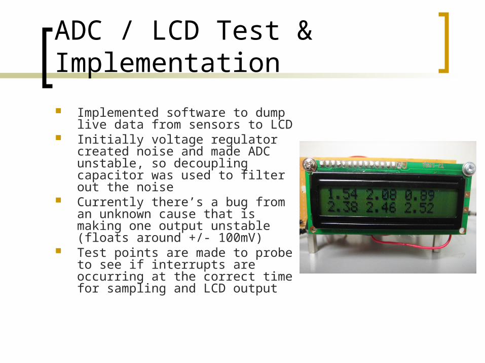
Implemented software to dump live data from sensors to LCD
Initially voltage regulator created noise and made ADC unstable, so decoupling capacitor was used to filter out the noise
Currently there’s a bug from an unknown cause that is making one output unstable (floats around +/- 100mV)
Test points are made to probe to see if interrupts are occurring at the correct time for sampling and LCD output
LVD & Sleep Mode Test & Results
Testing was successful Implemented Timer3 to be counter for
2minute delay Used power supply and led’s to
successfully show that 2 minute countdown was initiated
Microcontroller oscillators were stopped in sleep mode.
FAT16/MMC Implementation & Results
First Design Looked for Sample FAT16 File System Code
Second Design RS232 Serial Port / HyperTerminal Application
Checked to see if we are able to create directories, files, and read files on the SD/MMC.
Microcontroller PIC18F4680 Wrote code that would initialize SPI mode and let us
be able to write to the SD/MMC card. uALFAT is not being able to communicate with the
microcontroller. We believe through troubleshooting that this problem is a hardware problem. Another uALFAT is on order right now.
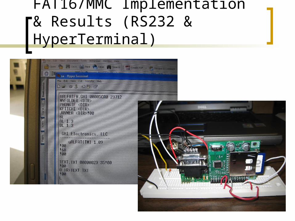
FAT16/MMC Implementation & Results (RS232 & HyperTerminal)
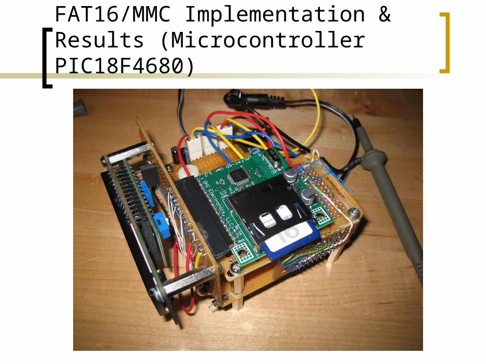
FAT16/MMC Implementation & Results (Microcontroller PIC18F4680)
Current Status
Sensor voltages can be captured and displayed on the LCD Device can run off of 5 AAA batteries, however 30minute run
time not yet tested Skeletal structure of hardware complete Firmware mostly complete Product casing design not started Downloading data to the MMC card currently not working
(hardware issue, communicating with vendor) Kalman Filter not implemented Conversion software’s file i/o portion is working but conversion
math not implemented in software Trying to figure out cause of floating voltage from one sensor
output

Q & A ??