Embed Size (px)
Citation preview
International Research Journal of Engineering and Technology (IRJET) e-ISSN: 2395 -0056
Volume: 04 Issue: 06 | June -2017 www.irjet.net p-ISSN: 2395-0072
© 2017, IRJET | Impact Factor value: 5.181 | ISO 9001:2008 Certified Journal | Page 1742
INJECTION MOLDING METHODS DESIGN, OPTIMIZATION, SIMULATION OF PLASTIC FLOW REDUCER PART BY MOLD FLOW
ANALYSIS
Vijaykumar Vilas Andhalkar 1 , Dr. S. R. Dulange 2
1 Department of Mechanical Engineering, P.G Student , A.G. Patil Institute Of Technology, Solapur 2 Department of Mechanical Engineering, Associate Professor, A.G. Patil Institute Of Technology, Solapur
---------------------------------------------------------------------***---------------------------------------------------------------------
Abstract - In this paper a component referred to as flow reducer where chosen for a comprehensive design review and mould flow analysis. The design of this product and the mould were made by the designing analysis software Autodesk Inventor software, Which is then simulated by the use of Autodesk Mold Flow software. The mold flow analysis is used to predict the deformation of the part, and then adjust the design accordingly and this is done using the Mold-Flow system Key Words: Injection moulding, Mould design, Mold flow simulation, Optimization Plastic Injection mould, Mould Flow Plastic Advisor (MPA)
1. INTRODUCTION Injection moulding is one of the most important processes in the plastic manufacturing industry. More than one-third of all plastic materials are injection molded, And the mold is one of the main components in the injection molding process. The Autodesk Simulation Moldflow results help to identify the main problem areas before the part is manufactured that are particularly difficult to predict with traditional methods. Analysis is essential for designing and mould making through simulation step-up and result interpretation to show how changes to wall thickness, gate location, material and geometry affects manufacturability and also experiments with “what-if” scenarios before finalizing a design. Injection Moulding simulation software into the mould design process in order to analyze the product, foresee the possible defects, and optimize the design to achieve the maximum outcome of the products with minimum cycle time in each production cycle. 2. PROBLEM DEFINITION: This work related to injection molding problems of pressure reducer plastic part of Arihant plastic industries at Barshi Dist.solapur. The part pressure reducer have frequent rejection due to incomplete cavity fill .Company wants to resolve this problem.
Fig2A.Defects in pressure reducer Part 3. OBJECTIVES OF THE WORK 1. To analyze the behavior of Thermoplastic material during the production cycle from the filling phase until the ejection phase 2. To foresee the possible problem for a product design; and therefore able to op-timize the design in the mould design process 3. To achieve the minimum production cycle time 4. To construct a rapid prototyping of the mould cavity design into a standard aluminum or steel mould plate 5.To prepare a product design for " reducer plastic part by using design analysis software 6. Using Mold Flow to simulate the polymer flow and finding out maximum clamp force and Fill time
4.Model details A 3d model of part pressure reducer is created in Autodesk Inventor software
Fig.4A )CAD Models For Pressure Reducer
International Research Journal of Engineering and Technology (IRJET) e-ISSN: 2395 -0056
Volume: 04 Issue: 06 | June -2017 www.irjet.net p-ISSN: 2395-0072
© 2017, IRJET | Impact Factor value: 5.181 | ISO 9001:2008 Certified Journal | Page 1743
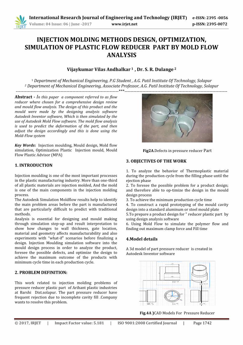
Fig 4B ) Actual Pressure reducer Part
5. Process settings Melt temperature: 170 (C) Mold temperature: 42 (C) Injection locations: 1 Max. machine injection pressure: 71 (MPa)
6. Material Data Family Name: VINYL-BASED RESIN(PVC,PVAC,PVAL…) Trade Name :FPVCFN01 Family Abbreviation :PVC Material Structure :Amorphous Mechanical Properties Basic Modulus 3280Mpa Poisson’s Ratio :0.42 Shear Modulus :1160 Mpa
7. Simulation Result
7. A Gate analysis Result The purpose of the analysis is to explore the most suitable gate location for the product design and to see the alternatives from best to fair until the worst location for the gate in relation of the flow resistance during the moulding cycle.
Fig.7. A)Best Gate Location
Fig7.B).Actual Part Gate Location
7.b )Fill Analysis Result The Fill Analysis is an important start of the analysis sequence in the Moldflow soft-ware. This analysis provides the behaviour of the thermoplastic material in the mould cavity during the filling phase. This analysis will calculate the flow front from the injec-tion location; therefore an injection(s) location needs to be selected before running this analysis.
Fig.7b) A Fill time analysis result for old process setting parameters
Fig.7b) B Fill time analysis result for NEW process setting parameters
International Research Journal of Engineering and Technology (IRJET) e-ISSN: 2395 -0056
Volume: 04 Issue: 06 | June -2017 www.irjet.net p-ISSN: 2395-0072
© 2017, IRJET | Impact Factor value: 5.181 | ISO 9001:2008 Certified Journal | Page 1744
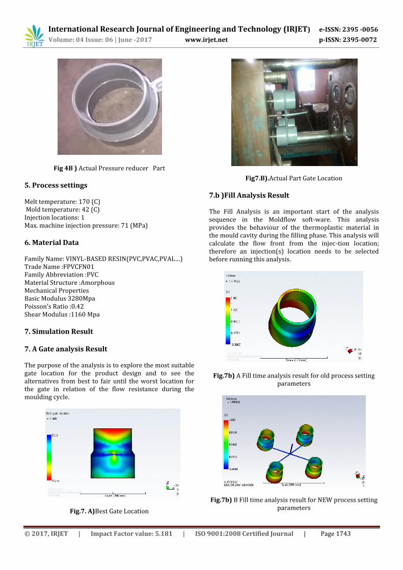
7C )Injection pressure Analysis result
7C )A Injection pressure analysis result for old process setting paramet
Fig. 7C )B Injection pressure analysis result for New process setting parameters
7D )Confidence of Fill Analysis result The confidence of fill result from the plastic filling analysis displays the probability of plastic filling a region within the cavity under conventional injection molding conditions. If the cavity does not fill (short shot), the changes must be made to the processing conditions, injection locations, design of the parts, or choice of the plastic. Table shows the risk of the part filling base on colors.
Fig. 6D ) A }Confidence of filling analysis result for Old process setting parameters
Fig. 7D ) B}Confidence of filling analysis result for New process setting parameters
7E )Flow Front Temperature Analysis result If the flow front temperature is too low in a thin area of the part, hesitation or short shot may be occurred. If it is too low in an area where weld lines are present, the weld lines may appear worse.
Fig. 7 E ) A }Temp at flow front Old methodology
Fig. 7 E ) B }Temp at flow front New methodology
International Research Journal of Engineering and Technology (IRJET) e-ISSN: 2395 -0056
Volume: 04 Issue: 06 | June -2017 www.irjet.net p-ISSN: 2395-0072
© 2017, IRJET | Impact Factor value: 5.181 | ISO 9001:2008 Certified Journal | Page 1745
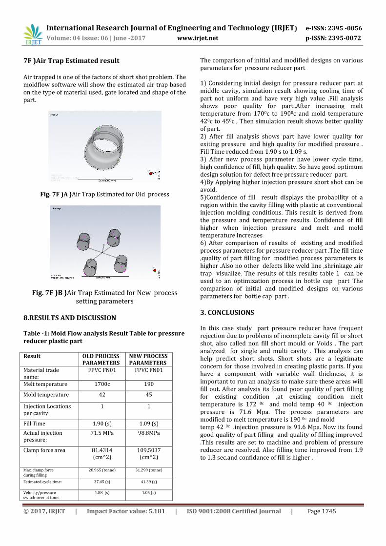
7F )Air Trap Estimated result Air trapped is one of the factors of short shot problem. The moldflow software will show the estimated air trap based on the type of material used, gate located and shape of the part.
Fig. 7F )A }Air Trap Estimated for Old process
Fig. 7F )B }Air Trap Estimated for New process setting parameters
8.RESULTS AND DISCUSSION Table -1: Mold Flow analysis Result Table for pressure reducer plastic part Result
OLD PROCESS PARAMETERS
NEW PROCESS PARAMETERS
Material trade name:
FPVC FN01 FPVC FN01
Melt temperature 1700c 190
Mold temperature 42 45
Injection Locations per cavity
1 1
Fill Time 1.90 (s) 1.09 (s)
Actual injection pressure:
71.5 MPa 98.8MPa
Clamp force area 81.4314 (cm^2)
109.5037 (cm^2)
Max. clamp force during filling
28.965 (tonne) 31.299 (tonne)
Estimated cycle time: 37.45 (s) 41.39 (s)
Velocity/pressure switch-over at time:
1.88 (s) 1.05 (s)
The comparison of initial and modified designs on various parameters for pressure reducer part 1) Considering initial design for pressure reducer part at middle cavity, simulation result showing cooling time of part not uniform and have very high value .Fill analysis shows poor quality for part..After increasing melt temperature from 1700c to 1900c and mold temperature 420c to 450c , Then simulation result shows better quality of part. 2) After fill analysis shows part have lower quality for exiting pressure and high quality for modified pressure . Fill Time reduced from 1.90 s to 1.09 s. 3) After new process parameter have lower cycle time, high confidence of fill, high quality. So have good optimum design solution for defect free pressure reducer part. 4)By Applying higher injection pressure short shot can be avoid. 5)Confidence of fill result displays the probability of a region within the cavity filling with plastic at conventional injection molding conditions. This result is derived from the pressure and temperature results. Confidence of fill higher when injection pressure and melt and mold temperature increases 6) After comparison of results of existing and modified process parameters for pressure reducer part .The fill time ,quality of part filling for modified process parameters is higher .Also no other defects like weld line ,shrinkage ,air trap visualize. The results of this results table 1 can be used to an optimization process in bottle cap part The comparison of initial and modified designs on various parameters for bottle cap part .
3. CONCLUSIONS In this case study part pressure reducer have frequent rejection due to problems of incomplete cavity fill or short shot, also called non fill short mould or Voids . The part analyzed for single and multi cavity . This analysis can help predict short shots. Short shots are a legitimate concern for those involved in creating plastic parts. If you have a component with variable wall thickness, it is important to run an analysis to make sure these areas will fill out. After analysis its found poor quality of part filling for existing condition ,at existing condition melt temperature is 172 0c and mold temp 40 0c .injection pressure is 71.6 Mpa. The process parameters are modified to melt temperature is 190 0c and mold temp 42 0c .injection pressure is 91.6 Mpa. Now its found good quality of part filling and quality of filling improved .This results are set to machine and problem of pressure reducer are resolved. Also filling time improved from 1.9 to 1.3 sec.and confidance of fill is higher .

International Research Journal of Engineering and Technology (IRJET) e-ISSN: 2395 -0056
Volume: 04 Issue: 06 | June -2017 www.irjet.net p-ISSN: 2395-0072
© 2017, IRJET | Impact Factor value: 5.181 | ISO 9001:2008 Certified Journal | Page 1746
REFERENCES 1. Auto desk Mold-Flow Insight material data warehouse. 2. wikimedia Foundation, Inc, 2010. InjectionMoulding. [online] Available at: <http://en. wikipedia. org/wiki/Injection_moulding> [Accessed 28 August 2010] 3. Bryce, D. M., ‘Plastic injection molding: Manufacturing process fundamental’. Society of Manufacturing Engineers, (1996) 4. Moldflow Plastic Insight, 2014. Moldflow Tutorial. [Software tutorial] Mold-flow Corporation 5. Tang, S.H., Kong, Y.M.,Sapuan, S.M., Samin, R., and Sulaiman, S., “Design and thermal analysis of plastic injection mold” , Journal of Materials Processing Technology, Vol. 171, pp. 259-267, 2006. 6.http://www.engineersedge.com/injection_molding,.htm, 2006 7.http://www.efunda.com/DesignStandards/plastic_design/plastic_intro.cfm, 2006 8. Mohd Amran, Siti Salmah, Zolkarnain Marjom, Umar Al-Amani, Raja Izamshah, Mohd Hadzley, Zulkeflee Abdullah, Mohd Sanusi “Warpage analysis verification between simulation and experimental of dumbbell plastic part in the injection moulding process” .International Symposium on Research in Innovation and Sustainability 2014 (ISoRIS ’14) 15-16 October 2014, Malacca, Malaysia Special Issue Sci.Int.(Lahore),26(4),1575-1579,2014 ISSN 1013-5316; CODEN: SINTE 8 9. Thi Truc-Ngan Huynh “Using Injection Molding Process for Manufacturing a HDPE Mini Wheel” J. Eng. Technol. Educ. (2013) 10(4): 450-466 December 2013 10. Yousef Amer, Mehdi Moayyedian, Zeinab Hajiabolhasani, and Lida Moayyedian “Improving injection moulding processes using Experimental design” World Academy of Science, Engineering and Technology Vol:7 2013-03-28 11.Manmit Salunke, Rushikesh Kate, Vishwas Lomate, Gajanan Sopal “Injection molding methods design, optimization, Simulation of plastic toy building block by moldFlow analysis” Volume 6, Issue 6, June (2015), pp. 33-41 Article ID: 30120150606004International Journal of Mechanical Engineering and Technology © IAEME: http://www.iaeme.com/IJMET.asp ISSN 0976 – 6340 (Print) ISSN 0976 – 6359 (Online) 12. Hariyanto Gunawan
and Willyanto Anggono “
Improving quality of injection mold using moldflow software simulationcase study: new design plastic cup” ISBN 979-15577-0-5, proceeding of international seminar on product design and development 2006 yogyakarta-indonesia, december 13 – 14, 2006 13.H Adithya Bhat, Sandeep Subramaniam, Arvind K. Pillai, Edu Krishnan L, M. Elangovan” “Analysis and design of mold for plastic side release buckle using moldflow software” eISSN: 2319-1163 | pISSN: 2321-7308 14. All about plastic moulding. 2009. The History of Plastic Moulding. [ONLINE] Available at: http://www.plasticmoulding.ca/history.htm#Plastic. [Accessed 10 October 11].
15.Murti, B, 2010. Simulation and analysis of Injection Moulding product and rapid prototyping. Bachelor. Finland: Arcada University.