Embed Size (px)
Citation preview
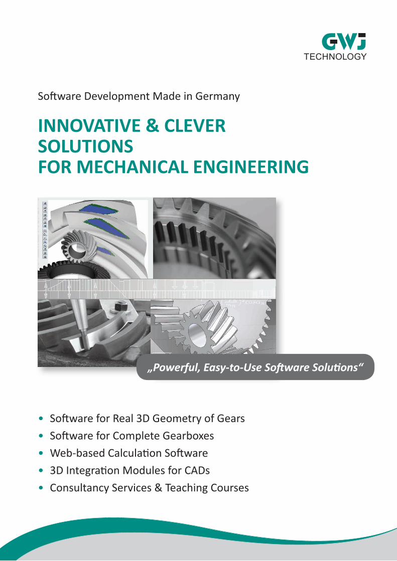
Software Development Made in Germany
INNOVATIVE & CLEVER SOLUTIONS FOR MECHANICAL ENGINEERING
• Software for Real 3D Geometry of Gears• Software for Complete Gearboxes• Web-based Calculation Software• 3D Integration Modules for CADs• Consultancy Services & Teaching Courses
„Powerful, Easy-to-Use Software Solutions“

www.gwj.de
GWJ Technology GmbH
Focusing on mechanical engineering, GWJ Technology, headquartered in Braunschweig, Germany, stands for high quality products and professional software development for the mechanical engineering to support engineers and designers in their daily work.
With keen insight and high energy, we put our utmost efforts, skills, knowledge and passion into our work to achieve top products.
Our portfolio includes the development of standard calculation software. From basic machine elements to complex systems, the software solutions are always flexible and can be integrated into intelligent 3D design and other environments.
GWJ Solutions Are
• Innovative and groundbreaking• Fast and easy to handle• Relative to practice and reliable
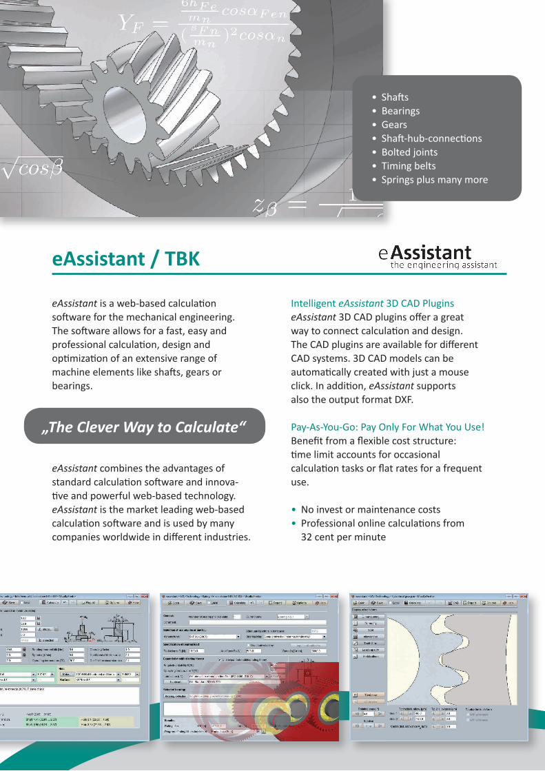
eAssistant / TBK
eAssistant is a web-based calculation software for the mechanical engineering.The software allows for a fast, easy and professional calculation, design and optimization of an extensive range of machine elements like shafts, gears or bearings.
eAssistant combines the advantages of standard calculation software and innova-tive and powerful web-based technology. eAssistant is the market leading web-based calculation software and is used by many companies worldwide in different industries.
Intelligent eAssistant 3D CAD PluginseAssistant 3D CAD plugins offer a great way to connect calculation and design. The CAD plugins are available for different CAD systems. 3D CAD models can be automatically created with just a mouse click. In addition, eAssistant supports also the output format DXF.
Pay-As-You-Go: Pay Only For What You Use!Benefit from a flexible cost structure: time limit accounts for occasional calculation tasks or flat rates for a frequent use.
• No invest or maintenance costs• Professional online calculations from 32 cent per minute
• Shafts• Bearings• Gears• Shaft-hub-connections• Bolted joints• Timing belts• Springs plus many more
„The Clever Way to Calculate“
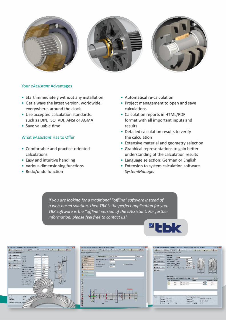
Your eAssistant Advantages
• Start immediately without any installation• Get always the latest version, worldwide, everywhere, around the clock• Use accepted calculation standards, such as DIN, ISO, VDI, ANSI or AGMA• Save valuable time
What eAssistant Has to Offer
• Comfortable and practice-oriented calculations• Easy and intuitive handling• Various dimensioning functions• Redo/undo function
• Automatical re-calculation• Project management to open and save calculations• Calculation reports in HTML/PDF format with all important inputs and results• Detailed calculation results to verify the calculation• Extensive material and geometry selection• Graphical representations to gain better understanding of the calculation results• Language selection: German or English• Extension to system calculation software SystemManager
If you are looking for a traditional "offline" software instead of a web-based solution, then TBK is the perfect application for you. TBK software is the "offline" version of the eAssistant. For further information, please feel free to contact us!
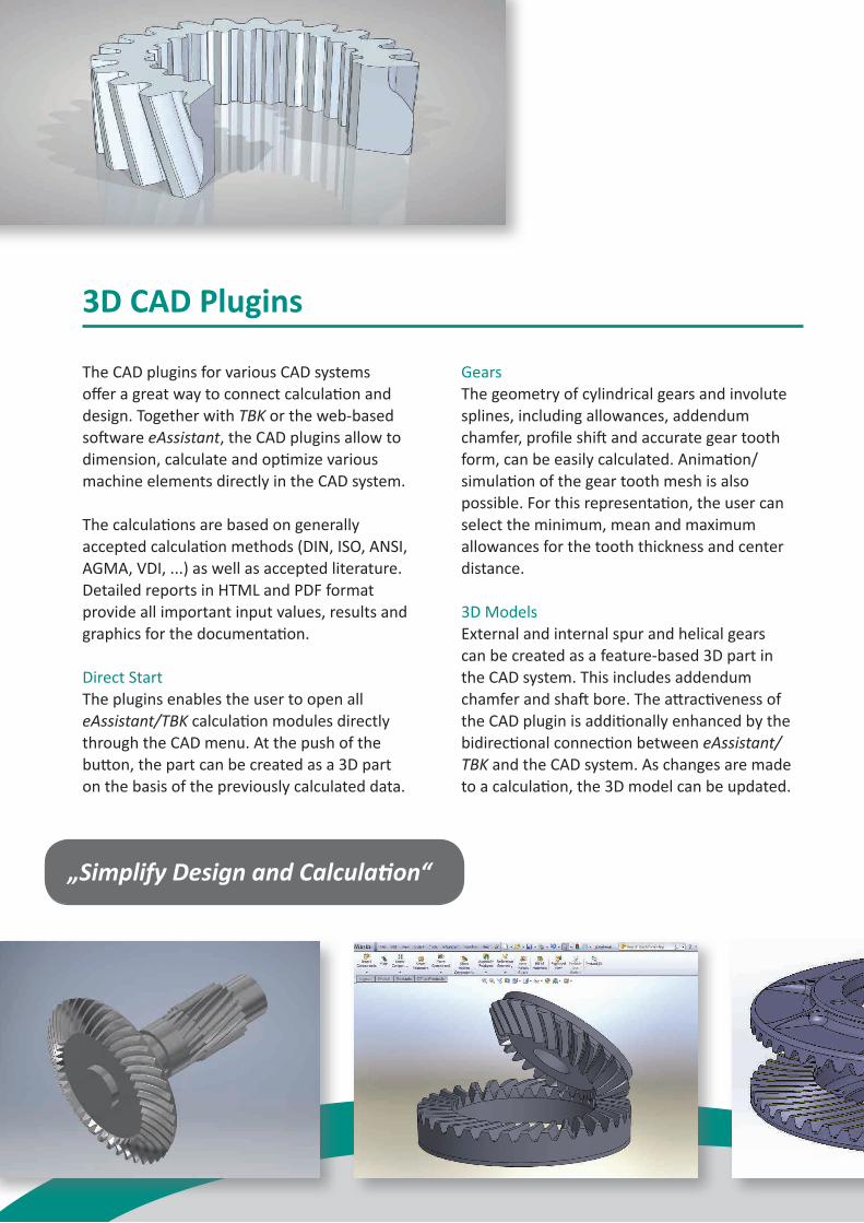
3D CAD Plugins
The CAD plugins for various CAD systems offer a great way to connect calculation and design. Together with TBK or the web-based software eAssistant, the CAD plugins allow to dimension, calculate and optimize various machine elements directly in the CAD system.
The calculations are based on generally accepted calculation methods (DIN, ISO, ANSI, AGMA, VDI, ...) as well as accepted literature. Detailed reports in HTML and PDF format provide all important input values, results and graphics for the documentation.
Direct StartThe plugins enables the user to open all eAssistant/TBK calculation modules directlythrough the CAD menu. At the push of the button, the part can be created as a 3D part on the basis of the previously calculated data.
GearsThe geometry of cylindrical gears and involute splines, including allowances, addendum chamfer, profile shift and accurate gear tooth form, can be easily calculated. Animation/simulation of the gear tooth mesh is also possible. For this representation, the user can select the minimum, mean and maximum allowances for the tooth thickness and center distance.
3D ModelsExternal and internal spur and helical gears can be created as a feature-based 3D part in the CAD system. This includes addendum chamfer and shaft bore. The attractiveness of the CAD plugin is additionally enhanced by the bidirectional connection between eAssistant/TBK and the CAD system. As changes are made to a calculation, the 3D model can be updated.
„Simplify Design and Calculation“
Bevel GearsThe CAD plugins support the creation of straight, helical and spiral bevel gears as a native 3D part directly in the CAD system.
Pinion ShaftsInvolute gears can be placed directly on an existing part. Furthermore, a tool runout for pinion shafts can be modeled. For this purpose, the user has to specify an offset (increase of the facewidth) or a radius for the cutter or grinding wheel.
Serrated and Splined ShaftsFor serrated and splined shaft connections, the shaft and hub profile can be generated as native 3D models based on the calculation. These can be also created in an already existing part.
Solid and Hollow ShaftsThe CAD plugin provides a very fast and comfortable generation of 3D shafts. Solid and
hollow shafts with an unlimited number ofcylindrical and conical shaft segments can be created as a bidirectional 3D part. Changes made to the calculation are reflected in the model.
Manufacturing Data in 2DWith just one click, the design table with all manufacturing details of cylindrical gears, bevel gears and involute splines can be placed on the manufacturing drawing. The appearance and size of that table is individually configurable. The advantage is that it eliminates the tedious and error prone process of having to manually add all design table parameters to the drawing.
Intelligent PartsThe calculation information is saved in the 3D model and can be opened at any time throughout the entire design phase. If a component contains several different calculation elements, it is possible to open the corresponding calculations.
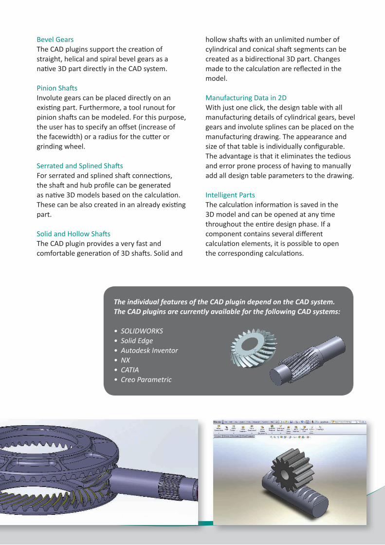
The individual features of the CAD plugin depend on the CAD system. The CAD plugins are currently available for the following CAD systems:
• SOLIDWORKS • Solid Edge• Autodesk Inventor• NX• CATIA• Creo Parametric
„Create Quickly and Easily Complex Gearboxes“
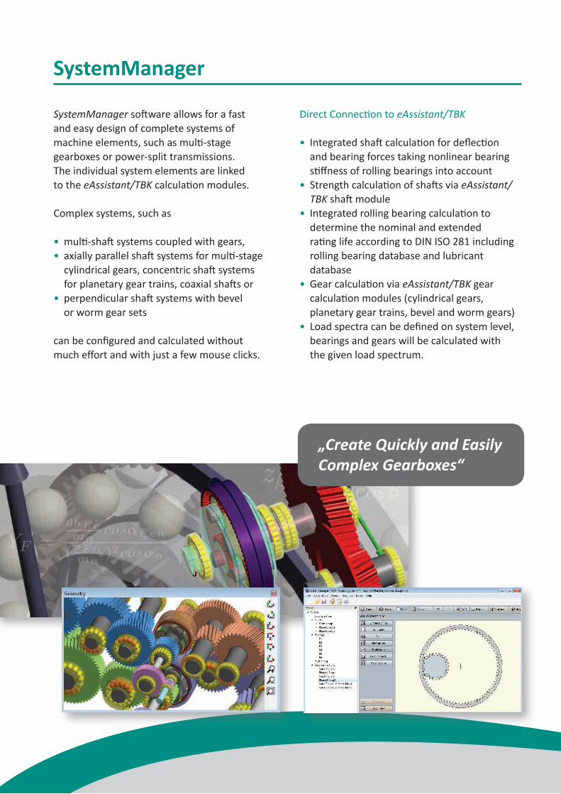
SystemManager
SystemManager software allows for a fast and easy design of complete systems of machine elements, such as multi-stage gearboxes or power-split transmissions. The individual system elements are linked to the eAssistant/TBK calculation modules.
Complex systems, such as
• multi-shaft systems coupled with gears,• axially parallel shaft systems for multi-stage cylindrical gears, concentric shaft systems for planetary gear trains, coaxial shafts or• perpendicular shaft systems with bevel or worm gear sets
can be configured and calculated withoutmuch effort and with just a few mouse clicks.
Direct Connection to eAssistant/TBK
• Integrated shaft calculation for deflection and bearing forces taking nonlinear bearing stiffness of rolling bearings into account• Strength calculation of shafts via eAssistant/ TBK shaft module• Integrated rolling bearing calculation to determine the nominal and extended rating life according to DIN ISO 281 including rolling bearing database and lubricant database• Gear calculation via eAssistant/TBK gear calculation modules (cylindrical gears, planetary gear trains, bevel and worm gears)• Load spectra can be defined on system level, bearings and gears will be calculated with the given load spectrum.
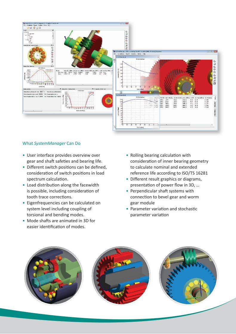
What SystemManager Can Do
• User interface provides overview over gear and shaft safeties and bearing life.• Different switch positions can be defined, consideration of switch positions in load spectrum calculation.• Load distribution along the facewidth is possible, including consideration of tooth trace corrections.• Eigenfrequencies can be calculated on system level including coupling of torsional and bending modes.• Mode shafts are animated in 3D for easier identification of modes.
• Rolling bearing calculation with consideration of inner bearing geometry to calculate nominal and extended reference life according to ISO/TS 16281• Different result graphics or diagrams, presentation of power flow in 3D, …• Perpendicular shaft systems with connection to bevel gear and worm gear module• Parameter variation and stochastic parameter variation
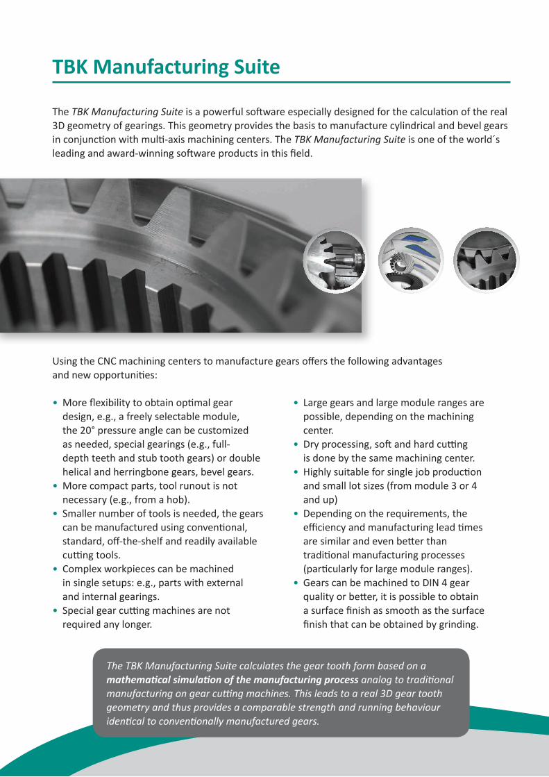
TBK Manufacturing Suite
The TBK Manufacturing Suite is a powerful software especially designed for the calculation of the real 3D geometry of gearings. This geometry provides the basis to manufacture cylindrical and bevel gears in conjunction with multi-axis machining centers. The TBK Manufacturing Suite is one of the world´s leading and award-winning software products in this field.
Using the CNC machining centers to manufacture gears offers the following advantages and new opportunities:
• More flexibility to obtain optimal gear design, e.g., a freely selectable module, the 20° pressure angle can be customized as needed, special gearings (e.g., full- depth teeth and stub tooth gears) or double helical and herringbone gears, bevel gears.• More compact parts, tool runout is not necessary (e.g., from a hob).• Smaller number of tools is needed, the gears can be manufactured using conventional, standard, off-the-shelf and readily available cutting tools.• Complex workpieces can be machined in single setups: e.g., parts with external and internal gearings.• Special gear cutting machines are not required any longer.
• Large gears and large module ranges are possible, depending on the machining center.• Dry processing, soft and hard cutting is done by the same machining center.• Highly suitable for single job production and small lot sizes (from module 3 or 4 and up)• Depending on the requirements, the efficiency and manufacturing lead times are similar and even better than traditional manufacturing processes (particularly for large module ranges).• Gears can be machined to DIN 4 gear quality or better, it is possible to obtain a surface finish as smooth as the surface finish that can be obtained by grinding.
The TBK Manufacturing Suite calculates the gear tooth form based on a mathematical simulation of the manufacturing process analog to traditional manufacturing on gear cutting machines. This leads to a real 3D gear tooth geometry and thus provides a comparable strength and running behaviour identical to conventionally manufactured gears.
Necessary RequirementsThe following requirements are necessary in order to use CNC machining centers to manufacture gears:
• CNC machining centers that comply with the requirements in terms of gear accuracy, boundary conditions for machinery installation have to be considered (e.g., foundation).• Machining technology and machining strategy have to be coordinated with gear manufacturing.• Real 3D geometry of the given gear tooth form is used as a starting point for CAM programming.
Short OverviewThe TBK Manufacturing Suite allows the calculation of involute cylindrical gears, for example:
• External and internal gears• Spur and helical gears• Involute splines
Cylindrical gears as well as involute splines (shaft and hub) can be manufactured based on the accurate gear tooth form.
The manufacturing of double helical and herringbone gears (with and without space in the center) is also possible.
Different types of bevel gears (geometry and load capacity) can be also calculated, for example:
• Straight and helical bevel gears including different forms of tooth depth• Spiral bevel gears
The output format of the 3D geometry is STEP and IGES. For the documentation, a single mouse click is enough to create a calculation report in HTML and PDF format.
The software is available in German, English and Chinese.
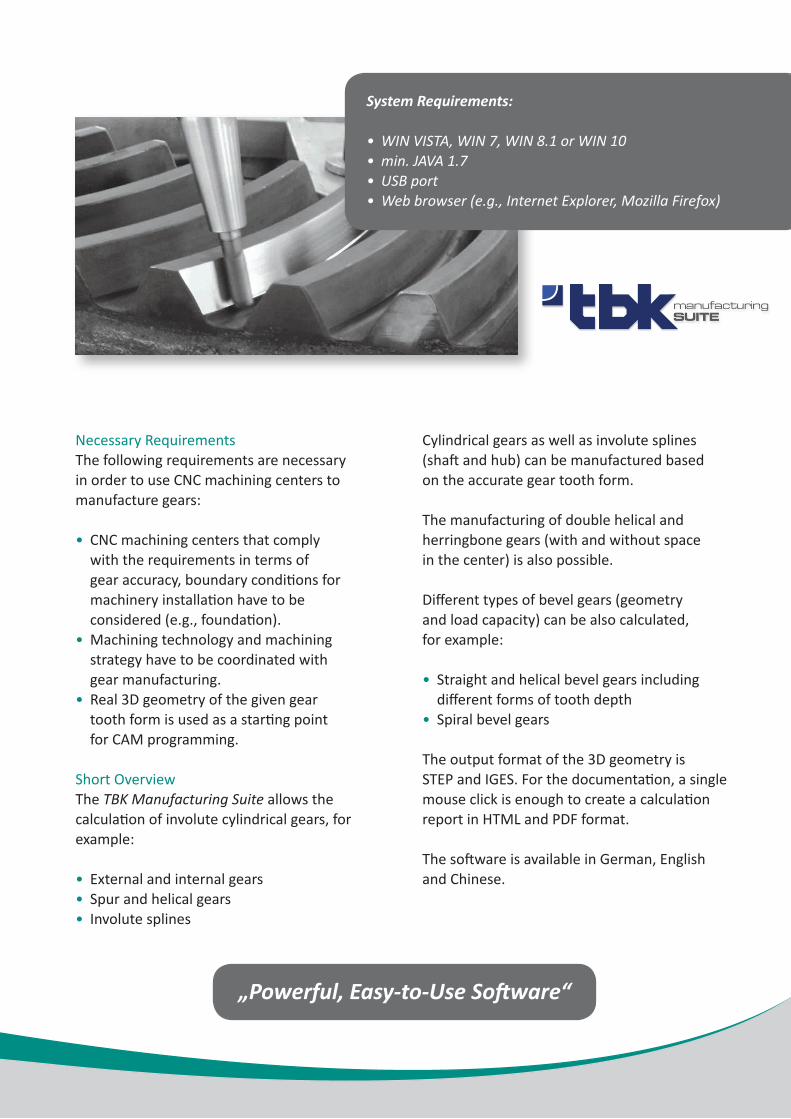
System Requirements:
• WIN VISTA, WIN 7, WIN 8.1 or WIN 10• min. JAVA 1.7• USB port• Web browser (e.g., Internet Explorer, Mozilla Firefox)
„Powerful, Easy-to-Use Software“
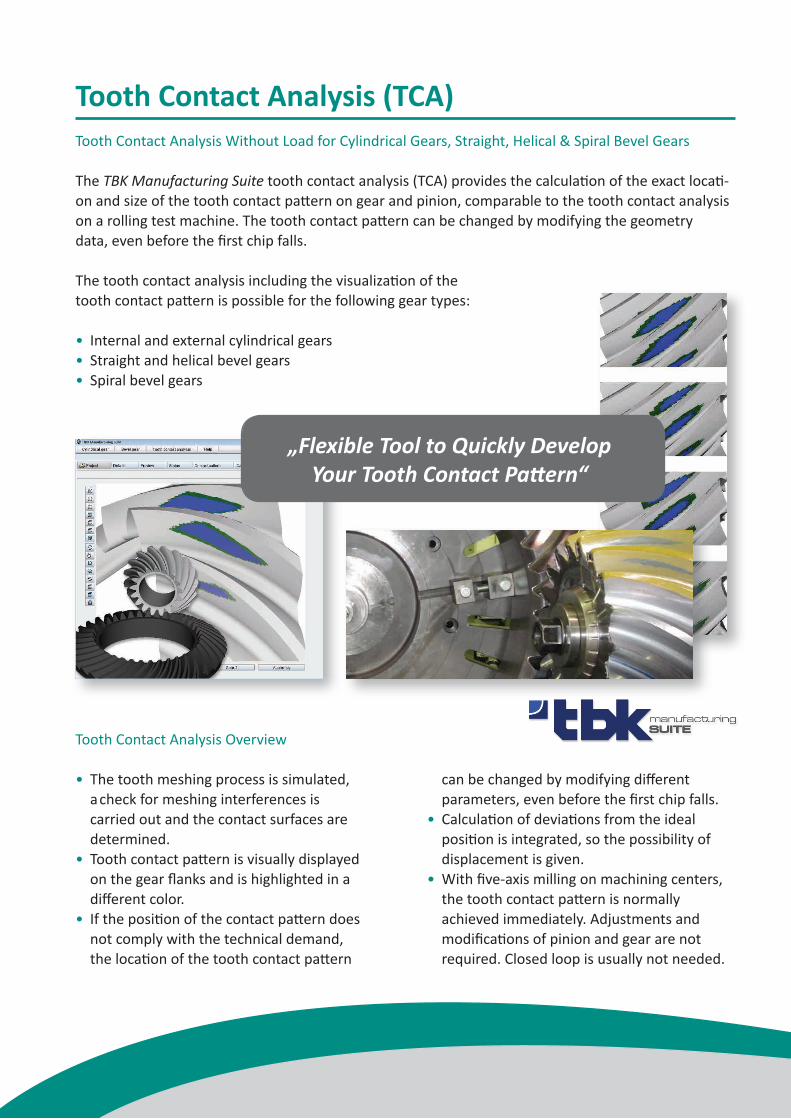
Tooth Contact Analysis (TCA)Tooth Contact Analysis Without Load for Cylindrical Gears, Straight, Helical & Spiral Bevel Gears
The TBK Manufacturing Suite tooth contact analysis (TCA) provides the calculation of the exact locati-on and size of the tooth contact pattern on gear and pinion, comparable to the tooth contact analysis on a rolling test machine. The tooth contact pattern can be changed by modifying the geometry data, even before the first chip falls.
The tooth contact analysis including the visualization of the tooth contact pattern is possible for the following gear types:
• Internal and external cylindrical gears• Straight and helical bevel gears• Spiral bevel gears
Tooth Contact Analysis Overview
• The tooth meshing process is simulated, a check for meshing interferences is carried out and the contact surfaces are determined.• Tooth contact pattern is visually displayed on the gear flanks and is highlighted in a different color.• If the position of the contact pattern does not comply with the technical demand, the location of the tooth contact pattern
can be changed by modifying different parameters, even before the first chip falls.• Calculation of deviations from the ideal position is integrated, so the possibility of displacement is given.• With five-axis milling on machining centers, the tooth contact pattern is normally achieved immediately. Adjustments and modifications of pinion and gear are not required. Closed loop is usually not needed.
„Flexible Tool to Quickly Develop Your Tooth Contact Pattern“
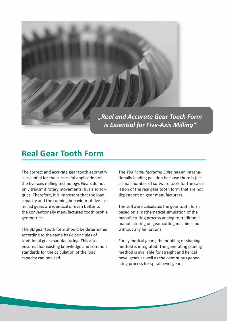
Real Gear Tooth Form
The correct and accurate gear tooth geometry is essential for the successful application of the five-axis milling technology. Gears do not only transmit rotary movements, but also tor-ques. Therefore, it is important that the load capacity and the running behaviour of five-axis milled gears are identical or even better to the conventionally manufactured tooth profile geometries.
The 3D gear tooth form should be determined according to the same basic principles of traditional gear manufacturing. This also ensures that existing knowledge and common standards for the calculation of the load capacity can be used.
The TBK Manufacturing Suite has an interna-tionally leading position because there is just a small number of software tools for the calcu-lation of the real gear tooth form that are not dependent on gear manufacturers.
The software calculates the gear tooth form based on a mathematical simulation of the manufacturing process analog to traditional manufacturing on gear cutting machines but without any limitations.
For cylindrical gears, the hobbing or shaping method is integrated. The generating planing method is available for straight and helical bevel gears as well as the continuous gener-ating process for spiral bevel gears.
„Real and Accurate Gear Tooth Form is Essential for Five-Axis Milling“
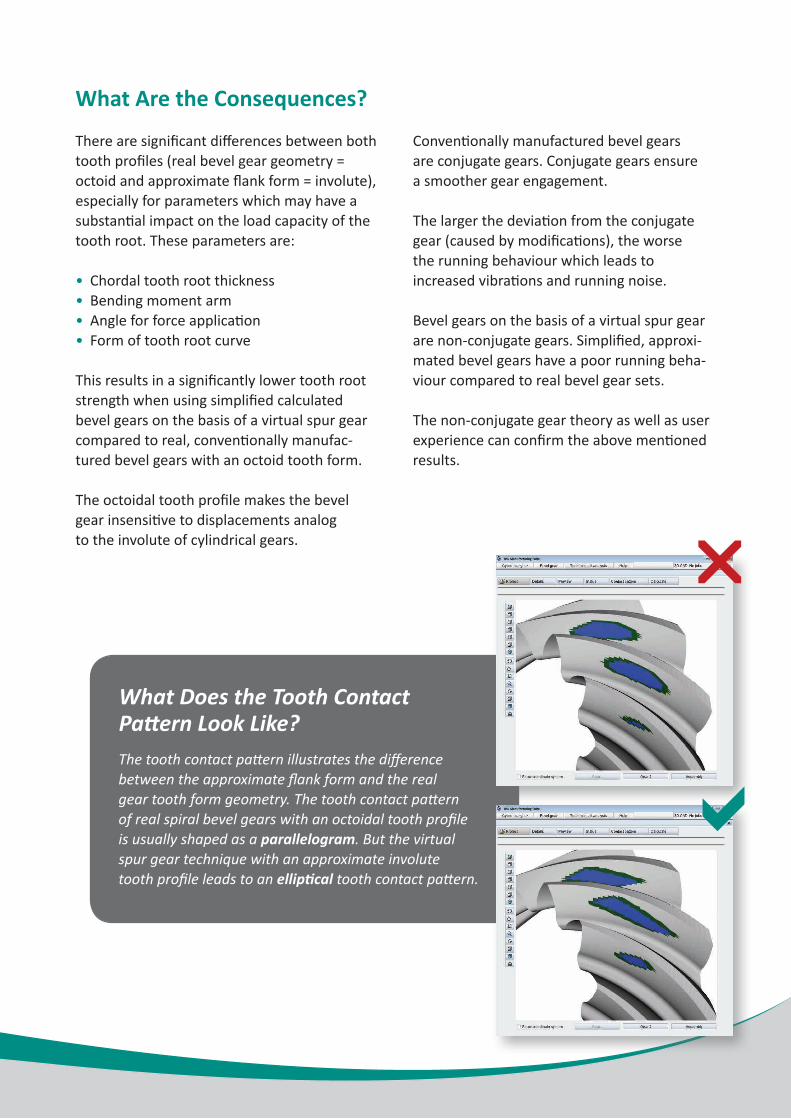
Bevel Gears
Most spiral bevels follow the octoid tooth form which is similar - but not identical - to the involute tooth form found on most cylindrical gears. There is only a small number of applications to determine the accurate 3D tooth form of bevel gears. To obtain this tooth form, a mathematical simulation of the manufacturing process is required and the develop-ment process is very complex, but necessary to achieve an accurate tooth model. Some available software solutions determine a simplified 3D bevel gear geometry based on a virtual spur gear to approximate the profile of a bevel gear. This technique assumes that the tooth form of a bevel gear follows an involute as a tooth form and not an octoidal tooth profile.
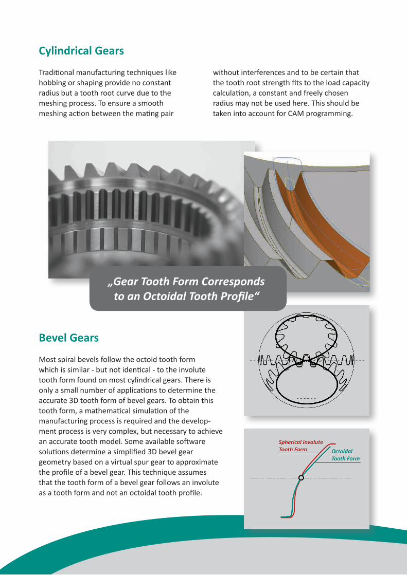
Cylindrical Gears
Traditional manufacturing techniques like hobbing or shaping provide no constantradius but a tooth root curve due to the meshing process. To ensure a smooth meshing action between the mating pair
without interferences and to be certain that the tooth root strength fits to the load capacity calculation, a constant and freely chosen radius may not be used here. This should be taken into account for CAM programming.
„Gear Tooth Form Corresponds to an Octoidal Tooth Profile“
What Are the Consequences?
There are significant differences between both tooth profiles (real bevel gear geometry = octoid and approximate flank form = involute), especially for parameters which may have a substantial impact on the load capacity of the tooth root. These parameters are:
• Chordal tooth root thickness• Bending moment arm• Angle for force application• Form of tooth root curve
This results in a significantly lower tooth root strength when using simplified calculated bevel gears on the basis of a virtual spur gearcompared to real, conventionally manufac-tured bevel gears with an octoid tooth form.
The octoidal tooth profile makes the bevel gear insensitive to displacements analog to the involute of cylindrical gears.
Conventionally manufactured bevel gears are conjugate gears. Conjugate gears ensure a smoother gear engagement.
The larger the deviation from the conjugate gear (caused by modifications), the worse the running behaviour which leads to increased vibrations and running noise.
Bevel gears on the basis of a virtual spur gear are non-conjugate gears. Simplified, approxi-mated bevel gears have a poor running beha-viour compared to real bevel gear sets.
The non-conjugate gear theory as well as user experience can confirm the above mentioned results.
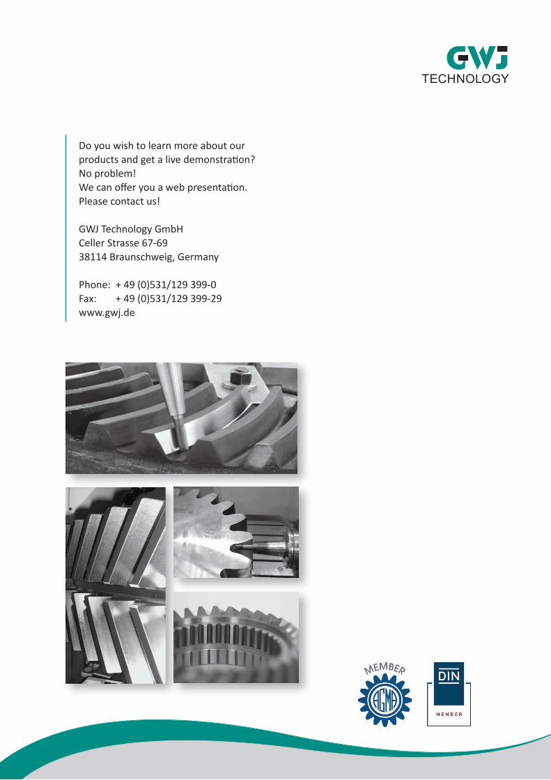
The tooth contact pattern illustrates the difference between the approximate flank form and the real gear tooth form geometry. The tooth contact pattern of real spiral bevel gears with an octoidal tooth profile is usually shaped as a parallelogram. But the virtual spur gear technique with an approximate involute tooth profile leads to an elliptical tooth contact pattern.
r
a
What Does the Tooth ContactPattern Look Like?
Do you wish to learn more about ourproducts and get a live demonstration? No problem!We can offer you a web presentation. Please contact us!
GWJ Technology GmbHCeller Strasse 67-6938114 Braunschweig, Germany
Phone: + 49 (0)531/129 399-0Fax: + 49 (0)531/129 399-29www.gwj.de