Embed Size (px)
Citation preview
UAS CONCEPT OF OPERATIONS AND VEHICLE TECHNOLOGIES DEMONSTRATION
Kurt Swieringa, NASA Langley Research Center, Hampton, VARaymond Young, Northeast UAS Airspace Research Alliance, Syracuse, NY
Robert Vivona, Aurora Flight Sciences, Cambridge MAMike Hague, Modern Technology Solutions, Inc, Alexandria, VA
AbstractIn 2017 and 2018, under National Aeronautics
and Space Administration (NASA) sponsorship, the New York Unmanned Aircraft Systems (UAS) Test Site and Northeast UAS Airspace Integration Research (NUAIR) Alliance conducted a year-long research project that culminated in a UAS technology flight demonstration. The research project included the creation of a concept of operations, and development and demonstration of UAS technologies. The concept of operations was focused on an unmanned aircraft transiting from cruise through Class E airspace into a high-density urban terminal environment. The terminal environment in which the test was conducted was Griffiss International Airport, under Syracuse Air Traffic Control (ATC) approach control and Griffiss control tower. Employing an Aurora Centaur optionally piloted aircraft (OPA), this project explored six scenarios aimed at advancing UAS integration into the National Airspace System (NAS) under both nominal and off-nominal conditions. Off-nominal conditions were defined to include complete loss of the communications link between the remote pilot’s control station on the ground and the aircraft. The off-nominal scenarios that were investigated included lost-link conditions with and without link recovery, an automated ATC initiated go-around, autonomous rerouting around a dynamic airspace obstruction (in this case simulated weather), and autonomous taxi operations to clear the runway.
IntroductionUnmanned aircraft have the potential to
revolutionize several different industries. Promising use cases for unmanned aircraft include, but are not limited to, telecommunications, cargo transportation, infrastructure inspection, and emergency response. In order to enable routine commercial UAS operations, UAS must be safely integrated into the NAS.
There is currently a community wide effort to integrate UAS into the NAS that includes standards groups, government, and industry. RTCA is a standards developing organization (SDO) comprised of government and industry participants, which has developed standards for Detect and Avoid (DAA) and Command and Control (C2) systems for large unmanned aircraft and is in the process of developing standards for low size, weight, and power systems that may be used onboard medium size UAS [1,2]. The Federal Aviation Administration is developing policies for the certification and integration of UAS into the NAS [3]. Private industry is developing UAS and working toward certification. NASA, the New York UAS Test Site, and NUAIR Alliance have been supporting these efforts by conducting research and providing testbed infrastructure [4-7].
In 2017, NASA contracted with the New York UAS Test Site to conduct a UAS technology flight demonstration during the summer of 2018, focused on an unmanned aircraft larger than 55 pounds and capable of operating in controlled airspace. The objective of the demonstration was to demonstrate a set of UAS technologies motivated by a concept of
operations for an unmanned aircraft arriving into a Class D airport. A second objective was to gain additional exposure to UAS technologies ahead of a series of demonstrations under NASA’s Systems Integration and Operationalization (SIO) activity, which is an ongoing partnership between NASA and industry. A further objective was to conduct safe UAS flight operations under stressful conditions as a way to increase UAS acceptance through demonstrating resiliency to off-nominal conditions.
The activity described in this paper began with the creation of a concept of operations and identification of technologies and procedures that would be able to address gaps or hazards. Within the one-year span of this activity, the technologies were prototyped and demonstrated aboard an Aurora Flight Sciences Centaur OPA. This activity also included ground-based DAA tests, which are described in [8], testing other DAA sensors, and work toward developing a redundant and cybersecure C2 link, although those parts of this activity are not covered in this paper.
This paper describes the flight demonstration conducted by Centaur. The paper begins with a concept of operations and a description of the technologies selected to be demonstrated. Next the New York UAS Test Site infrastructure, the airspace, and the Aurora Centaur OPA are described, followed by a description of the six flight demonstrations. The paper ends with a discussion of lessons learned and takeaways from this activity.
Concept of OperationsThis flight demonstration was based on a
concept of operations for an unmanned aircraft transiting from Class A airspace through Class E airspace into a Class C or D terminal environment, landing, and taxiing off the runway. The concept of operations includes both nominal operations and off-nominal operations. Off-nominal operations may include instances when the communications link between the unmanned aircraft and the ground
control station is broken (lost-link) and may also include the need for trajectory modifications due to hazards such as convective weather or traffic. This section summarizes the concept of operations that was demonstrated but does not include every detail.
The concept of operations was designed for beyond line of sight operations for unmanned aircraft that are greater than 55 pounds, arriving into a Class D airport. The unmanned aircraft was assumed to be flown by a remote pilot, who was responsible for communicating with air traffic control, following 14 CFR §91 flight rules, and following other applicable aviation rules and regulations. During nominal operations the unmanned aircraft would operate in much the same way as a manned aircraft, making integration into the NAS feasible. Further, it was also assumed that the UAS would fly under Instrument Flight Rules (IFR) and that ATC would provide the same separation services provided to manned aircraft.
It was assumed that the UAS would use a DAA system to remain well-clear of other traffic. The DAA system would use sensors and alerting algorithms to provide the remote pilot with information to ensure that the unmanned aircraft remained well clear of other traffic. Within this concept of operations, the assumption was that the DAA system could include airborne and ground based sensors and that the DAA system would be capable of detecting cooperative transponder-equipped aircraft or aircraft that are providing ADS-B information, and non-cooperative aircraft that may not have a transponder. It should be noted that while a high-level description of DAA was included in this concept of operations, this demonstration did not focus on rigorous DAA testing.
Figure 1 is an overview of the concept of operations used for this flight demonstration. During a nominal arrival, the unmanned aircraft descends from either Class A or E airspace. Similar to manned operations, the remote pilot notifies ATC of intent to begin descent to the destination airport.
2
After confirming that there is no conflicting traffic, ATC approach control authorizes the unmanned aircraft to proceed to the terminal area initial approach fix via a published/flight-planned route. The remote pilot monitors the traffic display and requests an ATC clearance when course deviations are necessary to remain well clear of other aircraft or hazardous weather. Lastly, the remote pilot executes an approach to the airport, coordinating with ATC to avoid traffic and weather as necessary. ATC approach control hands the unmanned aircraft off to the airport control tower for clearance to land. After receiving clearance to land, the unmanned aircraft lands and taxis off the runway.
When the communications link between the ground control station and the unmanned aircraft is lost, the functions of the remote pilot must either be handled by automation onboard the unmanned aircraft or through augmented procedures. In this concept of operations, a combination of technology, procedures, and a preprogrammed contingency flight path are employed to ensure that the unmanned aircraft can land safety with minimal disruption to the NAS.
3
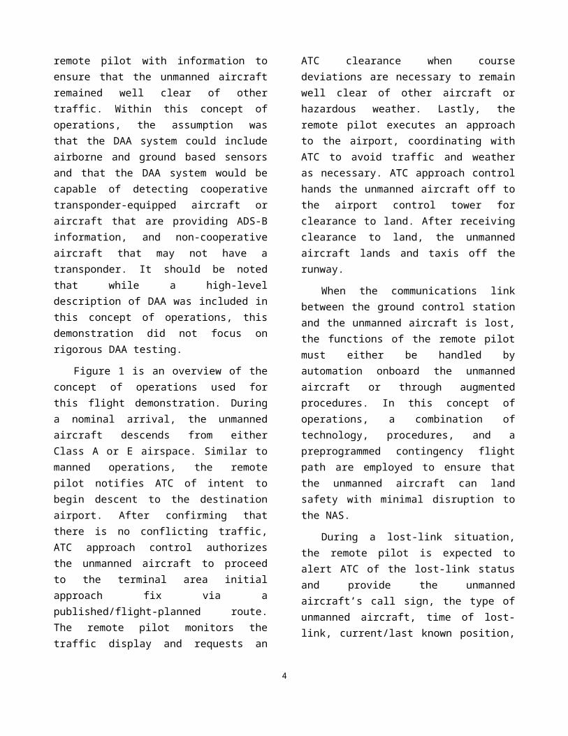
During a lost-link situation, the remote pilot is expected to alert ATC of the lost-link status and provide the unmanned aircraft’s call sign, the type of unmanned aircraft, time of lost-link, current/last known position, altitude, and direction of flight, and confirm its contingency procedure. Additionally, at the lost-link Notification Timer Offset, the unmanned aircraft squawks the pre-programmed lost-link code and broadcasts a pre-programmed notification of intent on appropriate emergency frequencies. ATC is responsible for ensuring other aircraft remain clear of the unmanned aircraft in accordance with normal emergency operations. The contingency procedure used in this flight demonstration included holding at a specified waypoint and then proceeding to land at a specified airport if the communications link was not reestablished within a specified period of time.
However, the preprogrammed procedure does not account for other off-nominal events that may occur when the unmanned aircraft is flying the preprogramed contingency route.
During a lost-link situation, an unmanned aircraft flying a preplanned contingency procedure may need the flexibility to handle dynamic events such as convective weather along the contingency route, an obstacle on the runway, or an obstacle on the taxiway. Additionally, it may be necessary for the unmanned aircraft to have the ability to autonomously taxi off the runway in order to avoid blocking an active runway for an extended period of time. The technologies described in the following section are possible methods for addressing these gaps.
4Figure 1: Concept of Operations
It should be noted that the authors do not claim that the technologies that were demonstrated as part of this activity should be implemented on every UAS. Instead, the specific concept of operations for each UAS should be evaluated to identify applicable hazards and either technological or procedural mitigations. Furthermore, the concept of operations developed for this activity did not address some advanced functionality that may be needed for particular commercial operations, such as how to handle contingency procedures that are updated during a flight (e.g., for an unmanned aircraft transiting from one airport to another), or procedures associated with a single pilot controlling multiple unmanned aircraft.
UAS Technologies DemonstratedThe concept of operations motivated the UAS
vehicle technologies that were demonstrated. Selected technologies were designed to address gaps in the concept of operations. Due to the limited time available to develop and integrate new technologies during this year-long activity, many of the technologies demonstrated were at a low- to moderate- level of maturity. Further, in order to prevent costly modifications to Centaur’s auto flight system, the safety pilot was often required to close the loop between the prototyped UAS technologies and the aircraft’s systems. Additional development and testing would be required before these technologies could be integrated into an operational system.
This paper discusses four different technologies that were demonstrated by the Aurora Centaur Optionally Piloted Aircraft (OPA). Those technologies include: automated lost-link procedures with synthesized voice notification of maneuvers, weather avoidance, ATC initiated go-around, and surface mapping and obstacle detection.
Automated lost-link procedures were developed and programmed into Centaur’s auto flight system and a voice synthesis system was
implemented to provide communication of maneuvers over a very high frequency (VHF) radio. If the communications link between Centaur and the ground control station were lost, Centaur would head direct to a specified waypoint, loiter for a period of time, and then proceed to the airport to land. When conducting these maneuvers, an automated voice transmission was generated by Centaur to alert air traffic controllers and other pilots on the VHF frequency about Centaur’s maneuvers.
An algorithm to maneuver around regions containing convective weather was developed and demonstrated. Weather detection was not addressed in this activity, since the focus of this demonstration was on the interactions between an unmanned aircraft, the remote pilot, and ATC. A weather avoidance capability could be used during both nominal and lost-link scenarios. As in the automated lost-link procedures, an automated voice transmission was generated by Centaur to notify ATC and other pilots on the frequency of Centaur’s maneuvers during a lost-link weather avoidance scenario. That automated voice transmission was again deemed to be useful since neither the pilot in command nor ATC were assumed to know of weather avoidance maneuvers in advance.
In addition to voice synthesis, a voice recognition algorithm was implemented to initiate a go-around based on a verbal command from ATC when the aircraft was in a lost-link situation. When an unmanned aircraft is in a lost-link situation, the remote pilot is unable to control the aircraft, and the aircraft must either rely on onboard automation or preprogrammed routes in order fly and land safely. One hazard that was identified was the possibility of an obstruction on a runway when an unmanned aircraft is attempting to land. The ability to recognize a voice command from air traffic control may provide unmanned aircraft in a lost-link situation with a mechanism for avoiding that hazard.
5
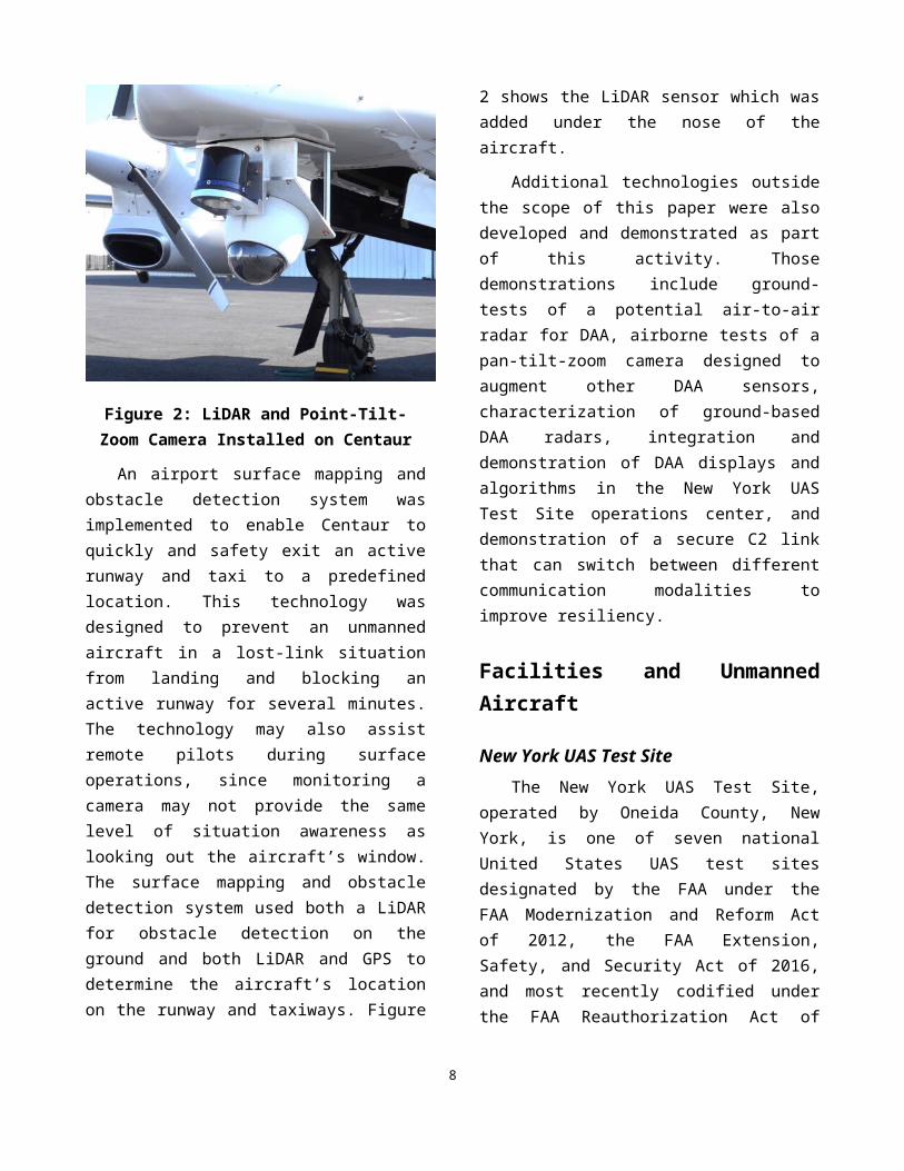
Figure 2: LiDAR and Point-Tilt-Zoom Camera Installed on Centaur
An airport surface mapping and obstacle detection system was implemented to enable Centaur to quickly and safety exit an active runway and taxi to a predefined location. This technology was designed to prevent an unmanned aircraft in a lost-link situation from landing and blocking an active runway for several minutes. The technology may also assist remote pilots during surface operations, since monitoring a camera may not provide the same level of situation awareness as looking out the aircraft’s window. The surface mapping and obstacle detection system used both a LiDAR for obstacle detection on the ground and both LiDAR and GPS to determine the aircraft’s location on the runway and taxiways. Figure 2 shows the LiDAR sensor which was added under the nose of the aircraft.
Additional technologies outside the scope of this paper were also developed and demonstrated as part of this activity. Those demonstrations include ground-tests of a potential air-to-air radar for DAA, airborne tests of a pan-tilt-zoom camera designed to augment other DAA sensors, characterization of ground-based DAA radars, integration and demonstration of DAA displays and algorithms in the New York UAS Test Site operations center, and
demonstration of a secure C2 link that can switch between different communication modalities to improve resiliency.
Facilities and Unmanned Aircraft
New York UAS Test SiteThe New York UAS Test Site, operated by
Oneida County, New York, is one of seven national United States UAS test sites designated by the FAA under the FAA Modernization and Reform Act of 2012, the FAA Extension, Safety, and Security Act of 2016, and most recently codified under the FAA Reauthorization Act of 2018. The mission of the FAA-designated UAS test sites is to contribute to FAA development of procedures, standards, and regulations necessary to support safe integration of UAS into the NAS. Under a teaming agreement with Oneida County, NUAIR acts as test site manager, responsible for UAS test range operational control and program management. A focus of the New York UAS Test Site and NUAIR is research, development, test, and evaluation for IFR-equipped UAS operations in the NAS.
Griffiss International AirportThe New York UAS Test Site’s base of
operations is Griffiss International Airport, a public-use airport owned and operated by Oneida County, New York. Griffiss International Airport has an 11,800-foot runway, Class D airspace, an operating air traffic control tower, and ample test range airspace for UAS test operations.
New York UAS Test Site AirspaceAs a non-federal public entity, Oneida County
holds FAA Certificates of Waiver or Authorization (COAs) for the New York UAS Test Site. These COAs give the New York UAS Test Site the ability to conduct UAS operations within the airspace and operational constraints defined in the enabling legislation and described in the COAs.
6
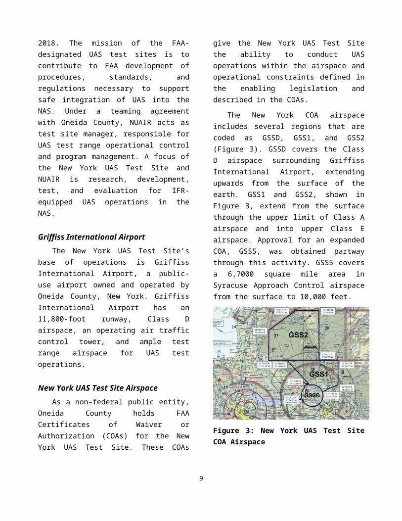
The New York COA airspace includes several regions that are coded as GSSD, GSS1, and GSS2 (Figure 3). GSSD covers the Class D airspace surrounding Griffiss International Airport, extending upwards from the surface of the earth. GSS1 and GSS2, shown in Figure 3, extend from the surface through the upper limit of Class A airspace and into upper Class E airspace. Approval for an expanded COA, GSS5, was obtained partway through this activity. GSS5 covers a 6,7000 square mile area in Syracuse Approach Control airspace from the surface to 10,000 feet.
Figure 3: New York UAS Test Site COA Airspace
In the Griffiss COA airspace, Boston Air Route Traffic Control Center (ZBW) has jurisdiction over airspace above 10,000 feet above mean sea level (MSL), and Syracuse Approach Control has jurisdiction below 10,000 feet MSL. All flights conducted for this activity were below 10,000 feet MSL; therefore, the flight demonstration team interacted with Syracuse Approach Control and the Griffiss Airport tower.
Ground-Based SurveillanceThe New York UAS Test Site has installed a
ground-based air traffic surveillance system. This test range instrumentation system can be used in conjunction with aircraft telemetry data to determine accurate position data, and as a test bed
for new ground and airborne sensors and aircraft platforms.
The sensors that comprise the ground-based surveillance system are: an SRC LSTAR V2 3-D radar, multiple SRC/Gryphon R1400 3-D X-band radars, and integrated Wide Area Multilateration (WAM) and Automatic Dependent Surveillance-Broadcast (ADS-B) ground stations. Additionally, a Saab SR-3 X-band surface movement radar provides accurate location data for airport surface traffic.
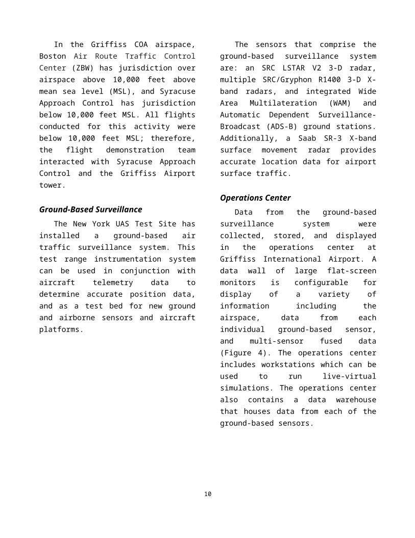
Operations CenterData from the ground-based surveillance
system were collected, stored, and displayed in the operations center at Griffiss International Airport. A data wall of large flat-screen monitors is configurable for display of a variety of information including the airspace, data from each individual ground-based sensor, and multi-sensor fused data (Figure 4). The operations center includes workstations which can be used to run live-virtual simulations. The operations center also contains a data warehouse that houses data from each of the ground-based sensors.
Figure 4: Operations Center at the New York UAS Test Site
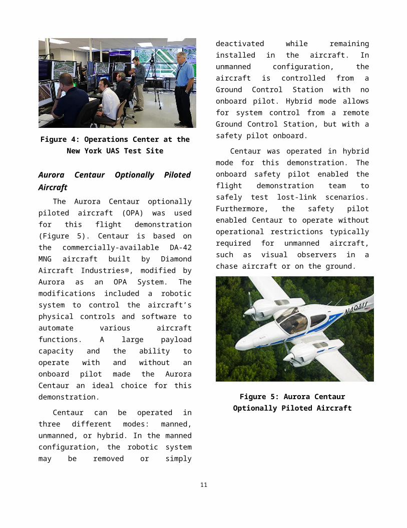
Aurora Centaur Optionally Piloted AircraftThe Aurora Centaur optionally piloted aircraft
(OPA) was used for this flight demonstration (Figure 5). Centaur is based on the commercially-
7
available DA-42 MNG aircraft built by Diamond Aircraft Industries®, modified by Aurora as an OPA System. The modifications included a robotic system to control the aircraft’s physical controls and software to automate various aircraft functions. A large payload capacity and the ability to operate with and without an onboard pilot made the Aurora Centaur an ideal choice for this demonstration.
Centaur can be operated in three different modes: manned, unmanned, or hybrid. In the manned configuration, the robotic system may be removed or simply deactivated while remaining installed in the aircraft. In unmanned configuration, the aircraft is controlled from a Ground Control Station with no onboard pilot. Hybrid mode allows for system control from a remote Ground Control Station, but with a safety pilot onboard.
Centaur was operated in hybrid mode for this demonstration. The onboard safety pilot enabled the flight demonstration team to safely test lost-link scenarios. Furthermore, the safety pilot enabled Centaur to operate without operational restrictions typically required for unmanned aircraft, such as visual observers in a chase aircraft or on the ground.
Figure 5: Aurora Centaur Optionally Piloted Aircraft
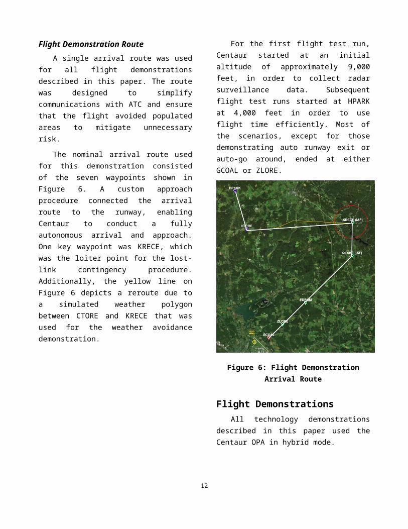
Flight Demonstration RouteA single arrival route was used for all flight
demonstrations described in this paper. The route
was designed to simplify communications with ATC and ensure that the flight avoided populated areas to mitigate unnecessary risk.
The nominal arrival route used for this demonstration consisted of the seven waypoints shown in Figure 6. A custom approach procedure connected the arrival route to the runway, enabling Centaur to conduct a fully autonomous arrival and approach. One key waypoint was KRECE, which was the loiter point for the lost-link contingency procedure. Additionally, the yellow line on Figure 6 depicts a reroute due to a simulated weather polygon between CTORE and KRECE that was used for the weather avoidance demonstration.
For the first flight test run, Centaur started at an initial altitude of approximately 9,000 feet, in order to collect radar surveillance data. Subsequent flight test runs started at HPARK at 4,000 feet in order to use flight time efficiently. Most of the scenarios, except for those demonstrating auto runway exit or auto-go around, ended at either GCOAL or ZLORE.
Figure 6: Flight Demonstration Arrival Route
8
Flight DemonstrationsAll technology demonstrations described in
this paper used the Centaur OPA in hybrid mode.
Centaur was controlled by a remote pilot using Centaur’s standard VCS-4586 ground control station, located within the Griffiss operations center.
Onboard the aircraft, a safety pilot monitored the aircraft for safe operations including performance of the remain well clear responsibilities through coordination with the remote pilot, since no DAA capabilities were on the aircraft and no chase aircraft was used. A flight test engineer, located on the aircraft, monitored the technologies being demonstrated and performed other operations required by the demonstrations.
Nominal ArrivalDuring the nominal arrival, the Centaur flew
the route from the first waypoint, HPARK, to the last waypoint GCOAL. During the approach, the aircraft descended to 3000 feet MSL at EDRUM and 1500 feet MSL at GCOAL. Throughout the flight, either the remote pilot or the safety pilot interacted with ATC as a manned pilot aircraft would. This included handoffs between Syracuse Approach Control and the Griffiss tower, obtaining clearance to land, and responding to any other ATC instructions.
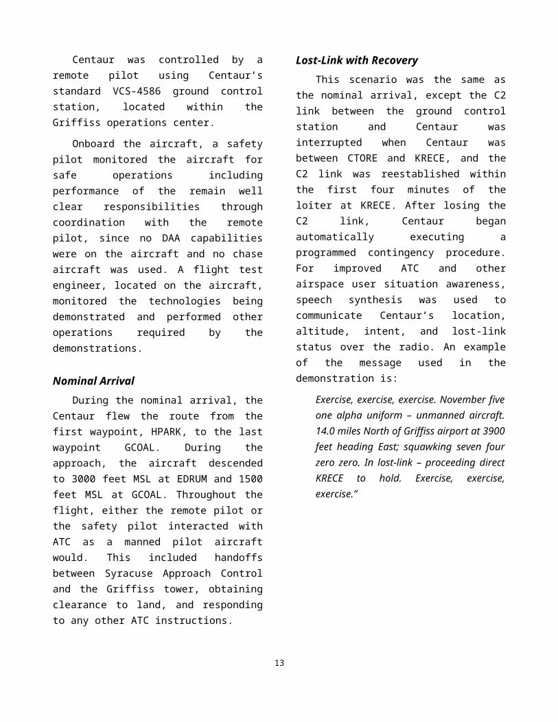
Lost-Link with RecoveryThis scenario was the same as the nominal
arrival, except the C2 link between the ground control station and Centaur was interrupted when Centaur was between CTORE and KRECE, and the C2 link was reestablished within the first four minutes of the loiter at KRECE. After losing the C2 link, Centaur began automatically executing a programmed contingency procedure. For improved ATC and other airspace user situation awareness, speech synthesis was used to communicate Centaur’s location, altitude, intent, and lost-link
status over the radio. An example of the message used in the demonstration is:
Exercise, exercise, exercise. November five one alpha uniform – unmanned aircraft. 14.0 miles North of Griffiss airport at 3900 feet heading East; squawking seven four zero zero. In lost-link – proceeding direct KRECE to hold. Exercise, exercise, exercise.”
It should be noted that the word “exercise” was used to indicate that this was a demonstration. In an actual lost-link scenario, the remote pilot would be required to notify ATC that the unmanned aircraft was in a lost-link situation and to ensure that ATC was aware of the contingency route the unmanned aircraft would follow.
As shown in Figure 7, Centaur proceeded direct-to KRECE and began to loiter in accordance with the preprogrammed lost-link procedure.
9
Figure 7: Lost-Link with Recovery Scenario
Partway through the loiter, the C2 link was reestablished and Centaur continued its descent to the airport.
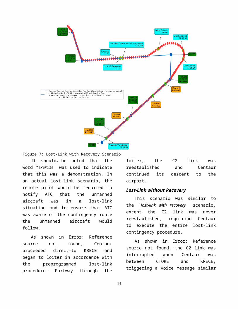
Lost-Link without RecoveryThis scenario was similar to the “lost-link with
recovery” scenario, except the C2 link was never reestablished, requiring Centaur to execute the entire lost-link contingency procedure.
As shown in Figure 8, the C2 link was interrupted when Centaur was between CTORE and KRECE, triggering a voice message similar to the one described in the previous section:
“Exercise, exercise, exercise. November five one alpha uniform – unmanned aircraft. 13.4 miles North of Griffiss airport at 4000 feet; heading East; squawking seven four zero zero. in lost-link – proceeding direct KRECE to hold. Exercise, exercise, exercise.”
Centaur then proceeded direct-to KRECE and began a nine-minute loiter, after which Centaur would proceed to land at the airport if the C2 link could not be reestablished. Five minutes prior to exiting the loiter a second message was transmitted from Centaur over the radio:
“Exercise, exercise, exercise. November five one alpha uniform – unmanned aircraft. Holding at KRECE; squawking seven four zero zero. in lost-link – executing approach to Griffiss airport in 5 minutes. Exercise, exercise, exercise.”
The purpose of this message was to notify ATC and other airspace users that Centaur would exit the loiter and proceed to land at the airport if the C2 link could not be reestablished. When designing these procedures, this second message was deemed to be particularly important if the loiter time was long, since ATC and other airspace users may lose
10
: Lost-Link without Recovery Scenario
awareness of when the loiter would end. For example, the loiter time specified in the New York UAS Test Site COA is 30 minutes long but was shortened to nine minutes for the purpose of this demonstration.
Five minutes after transmitting the message, Centaur exited the loiter area and flew the preprogrammed route toward the runway. During a real lost-link situation, the unmanned aircraft would automatically land. Since flying the approach and landing were demonstrated during other scenarios, this scenario ended at GCOAL in order to facilitate efficient use of flight time.
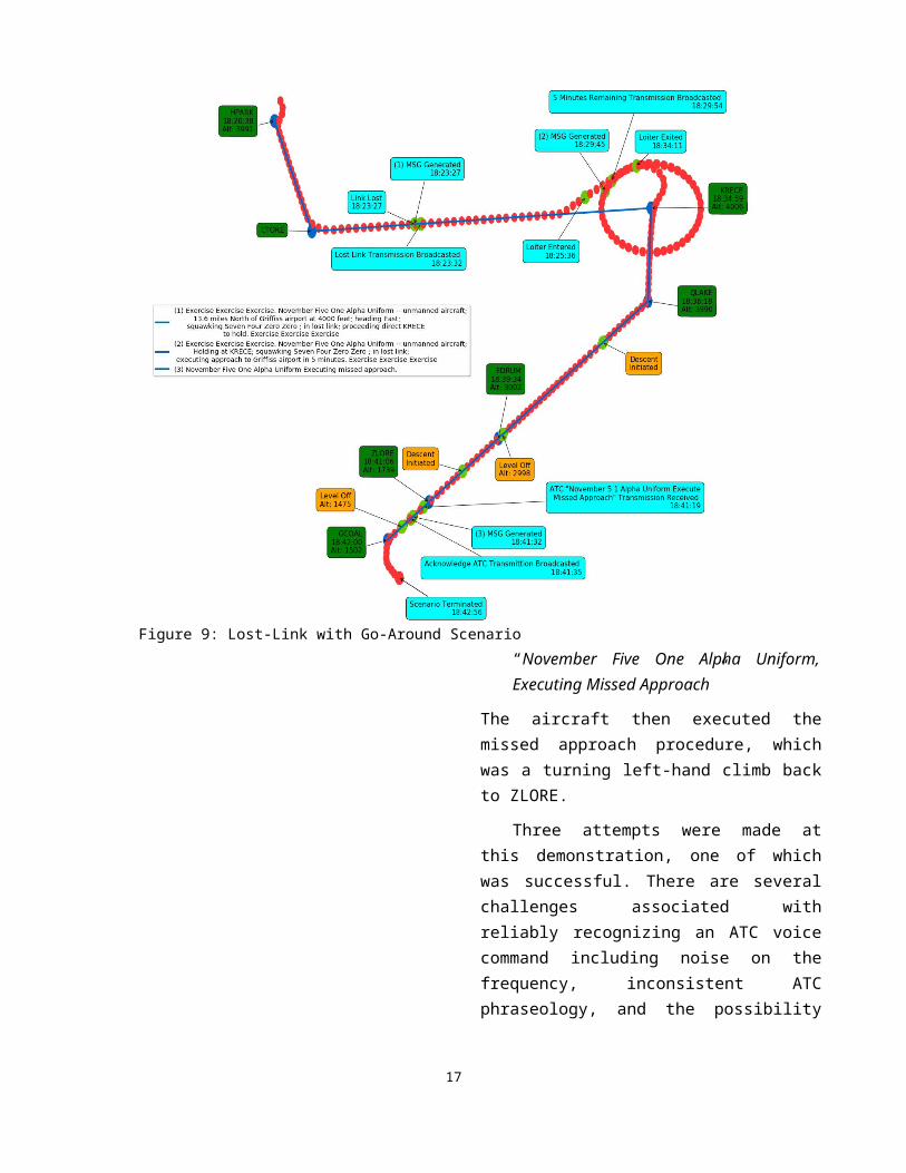
Lost-Link with Go-AroundThis scenario was the same as the “lost-link
without recovery” scenario, except a voice recognition system enabled Centaur to recognize a go-around command from the Griffiss Tower when Centaur crossed ZLORE (Figure 9).
The rationale for implementing the voice recognition system was to provide ATC with a mechanism of communicating a go-around command if a hazard existed on the runway.
In order to support this demonstration, a speech recognition system was implemented on the aircraft. The speech recognition was tuned to identify the phrase “November Five One Alpha Uniform, Execute Missed Approach.”
When Centaur crossed ZLORE, the Griffiss tower controller requested the go around by transmitting on the tower frequency:
“November Five One Alpha Uniform, Execute Missed Approach.”
The system onboard Centaur automatically identified this request and transmitted a response:
11
“November Five One Alpha Uniform, Executing Missed Approach”
The aircraft then executed the missed approach procedure, which was a turning left-hand climb back to ZLORE.
Three attempts were made at this demonstration, one of which was successful. There are several challenges associated with reliably recognizing an ATC voice command including noise on the frequency, inconsistent ATC phraseology, and the possibility of a bad actor spoofing an ATC communication. Furthermore, the system used in this demonstration was relatively immature and it is clear that improvements could be made with additional voice recognition training. These, and other challenges, are covered in the discussion section below.
Lost-Link with Weather AvoidanceThis demonstration was an example of a
scenario where the aircraft is forced to make a deviation from its predefined lost-link procedure due to an external disturbance. In this scenario the C2 link was interrupted between CTORE and KRECE, triggering the following lost-link message transmitted over the radio:
“Exercise, exercise, exercise. November five one alpha uniform – unmanned aircraft. 13.4 miles North of Griffiss airport at 4000 feet; heading East; squawking seven four zero zero. in lost-link – proceeding direct KRECE to hold. Exercise, exercise, exercise.”
After the C2 link was interrupted, the flight test engineer placed a simulated weather event between CTORE and KRECE, which required
12
Figure 9: Lost-Link with Go-Around Scenario
Centaur to plan a new path in order to avoid the simulated weather. Centaur transmitted an automated message on the radio to communicate the new path to ATC and to other aircraft in the area.
“Exercise, exercise, exercise. November five one alpha uniform – unmanned aircraft. 13.6 miles North of Griffiss airport at 4000 feet; turning left 20 degrees for weather. Expect direct KRECE in 1 minute. Exercise, exercise, exercise.”
As shown in Figure 10, Centaur conducted a maneuver to avoid the weather and transmitted another message indicating when Centaur was clear of the weather and again proceeding direct to KRECE to begin loitering, as per the original procedure.
“Exercise, exercise, exercise. November five one alpha uniform – unmanned aircraft. 15.4 miles North of Griffiss airport at 3900 feet; proceeding direct KRECE to hold. Exercise, exercise, exercise.”
Five minutes prior to the end of the loiter, Centaur transmitted another voice message over the radio to indicate that it would exit the loiter five minutes later and proceed toward the airport. The scenario ended after Centaur crossed ZLORE.
Surface Awareness and Obstacle DetectionThe objective of this scenario was to
demonstrate the ability of an unmanned aircraft to taxi off the runway while avoiding obstacles during a lost-link condition. Sensors were added to Centaur to sense its location on the runway or taxiway,
13
: Lost-Link with Weather Avoidance Scenario
determine the first runway exit after landing, and detect obstacles.
The demonstration scenario is illustrated on the Griffiss Airport map shown in Figure 11. The aircraft landed on runway 33 prior to Taxiway D, proceeded past taxiway D and exited on taxiway C. After crossing taxiway A and approaching the apron, a truck was positioned as an obstacle after entering the apron. The truck location was placed so the aircraft would stop after leaving the active taxiways.
The demonstration was performed under the control of the safety pilot, who landed the aircraft and taxied the aircraft to the apron. When the aircraft landed, an engineering display showed the first runway exit and the location of the aircraft on the runway or taxiway. The test engineers and the
remote pilot observed the engineering display during the taxi maneuver to confirm that the location, intersection, and maneuver information was correct during taxi to the apron. When the truck was observed by the system, the remote pilot radioed the safety pilot to stop. Once stopped, the truck was cleared, and the aircraft was allowed to taxi to its parking location.
The demonstration was executed successfully. The localization system worked well enough that the remote pilot and test team could monitor both during taxi out and taxi in during the actual demonstration. A couple of minor issues were observed:
1. LiDAR would temporarily pick up obstacles off the edges of the taxiways as it was turning. This obstacle detection flickering issue could be resolved with more refined algorithms which could understand how the aircraft was maneuvering, i.e., knowing that the aircraft was turning so the obstacles were not actually in the expected path of the aircraft
2. The “exit maneuver” criteria only worked effectively on the runway and not on the taxiways. This was expected since the system was not designed to be aware of the taxi plan, so when crossing a taxiway intersection where there were multiple valid turns, the system would need to be provided information on the intended path of the aircraft.
3. The “Next intersection” determination would not switch as quickly as desired. This logic needed better information about the aircraft dynamics to more accurately determine when an exit is no longer viable.
With minor improvements, this system would be a viable operational solution, though it would benefit from a more powerful LiDAR. The LiDAR chosen for this demonstration was purposely chosen for its low power to see how well it would perform. The main advantage to a more powerful LiDAR for this application would be better obstacle detection range.
14
Figure 11: Surface Awareness and Obstacle Detection Scenario
DiscussionThe UAS technologies that were demonstrated
as part of this activity were intended to showcase how an unmanned aircraft could interact with ATC and other aircraft during an off-nominal lost-link situation. The concept of operations and UAS technologies developed for this demonstration assumed that there was a remote pilot in command of the aircraft. However, several of the ideas presented in this paper may also be applicable to unmanned aircraft with a greater level of autonomy. This section describes some of the lessons that were learned throughout this activity.
During the lost-link scenarios, Centaur automatically generated voice messages to notify both ATC and other aircraft of its intent. When there are no dynamic route modifications and the preprogrammed contingency route is followed, the automated voice messages are redundant with communications between the remote pilot and ATC. This is because the remote pilot is required to notify ATC of any lost-link situations and the unmanned aircraft’s contingency procedure. However, the automated messages still have the benefit of providing situation awareness to other aircraft in the area. The automated messages become significantly more useful when the unmanned aircraft must make dynamic modifications to the preprogrammed contingency route. In that situation, neither the remote pilot nor the ATC has knowledge of what the unmanned aircraft’s intended route is; therefore, the automated messages will enhance situation awareness. Additional feedback about the automated messages suggested a desire to make the messages as short as possible and emphasized the need for automation to prevent the unmanned aircraft from stepping on other transmissions, a task handled by the flight test engineer for this demonstration.
The capability to recognize and implement a go-around command from ATC was implemented as an additional layer of safety. The concept of operations specifies that the remote pilot notify
ATC when the unmanned aircraft has lost its C2 link. It is then ATC’s responsibility to ensure that the airspace and runway are clear. However, without an alternate communication method, neither ATC nor the remote pilot would have a mechanism of waving off the unmanned aircraft if there was an obstruction on the runway. During this demonstration, there were several challenges identified with ATC voice recognition. Technical challenges include noisy voice transmissions and ATC phraseology that may not always be consistent with the specified command. Additionally, voice commands provided over the radio that modify the unmanned aircraft’s route present a security vulnerability. Limiting acceptance of the message to cases where the unmanned has lost its C2 link and is within a specified range of the airport would limit exposure to bad actors; however, it is not clear if those techniques would be sufficient. The future use of Controller Pilot Data Link Communications (CPDLC) may provide a method of transmitting commands from ATC without the technical and security challenges associated with voice commands.
The surface awareness and obstacle detection system was designed to ensure that an unmanned aircraft that had lost its C2 link could safely clear an active runway in a timely manner. If the unmanned aircraft is unable to autonomously taxi off the runway and the C2 link cannot be reestablished, the aircraft may need to be towed off the runway. This would result in a significant disruption to operations and would likely not be acceptable to ATC. Furthermore, towing the unmanned aircraft would be problematic if the unmanned aircraft’s support crew are not located at the contingency airport or if the unmanned aircraft lands at a time when the airport is minimally staffed.
SummaryA flight demonstration of UAS technologies
was sponsored by NASA and conducted at the New York UAS Test Site and their partners during the
15
summer of 2018. The purpose of the flight demonstration was to showcase technologies designed to minimize the impact of an interrupted C2 link between an unmanned aircraft and its ground control station. The technologies that were selected for demonstration were derived from a concept of operations and prototyped for this activity.
For the demonstration, the Aurora Centaur OPA conducted six different demonstrations, including a nominal arrival scenario and the following five lost-link scenarios:
the C2 link was lost and later reestablished, the C2 link was lost and not reestablished, the C2-link was lost, and a go-around
maneuver was required, the C2 link was lost and a weather
avoidance maneuver was required, and the C2 link was lost and the aircraft was
required to autonomously taxi off the runway.
In general, the demonstrations were completed successfully, though additional development and testing would be necessary before the prototype systems could be used in commercial systems. The concept of operations and demonstration emphasized the importance of communication with ATC if an unmanned aircraft in a lost-link scenario is required to modify its preplanned trajectory to avoid hazards such as weather. This flight demonstration also served the purpose of raising ATC awareness and familiarity with UAS operations; particularly with lost-link operations.
References[1] RTCA, 2017, Minimum Operational Performance Standards (MOPS) for Detect and Avoid (DAA) Systems, Washington, DC, RTCA DO-365
[2] RTCA, 2017, Detect and Avoid (DAA) White Paper Phase 2, Washington, DC, RTCA SC-228 WP-3
[3] FAA, 2012, Integration of Unmanned Aircraft Systems into the National Airspace System Concept of Operations V2.0
[4] Wu, Gilbert, Andrew Cone, 2019, Detect and Avoid Alerting Performance with Limited Surveillance Volume for Non-Cooperative Aircraft, San Diego, CA, 2019 AIAA Science and Technology Forum and Exposition
[5] Rorie, Conrad, Lisa Fern, 2018, An Interoperability Concept for Detect and Avoid and Collision Avoidance Systems: Results from a Human-in-the-Loop Simulation, Atlanta, GA, 2018 Aviation Technology, Integration, and Operations Conference, AIAA AVIATION Forum, (AIAA 2018-2875)
[6] Hardy, Jermey, Devin Jack, Keith Hoffler, 2018, Sensitivity Analysis of Detect and Avoid Well Clear Parameter Variations on UAS DAA Sensor Requirements, Atlanta, GA, 2018 Aviation Technology, Integration, and Operations Conference, AIAA AVIATION Forum, (AIAA 2018-3505)
[7] Vincent, Michael, Anna Trujillo, Devin Jack, Keith Hoffler, 2018, A Recommended DAA Well-Clear Definition for the Terminal Environment, Atlanta, GA, 2018 Aviation Technology, Integration, and Operations Conference, AIAA AVIATION Forum, (AIAA 2018-2873)
[8] Young, Raymond, 2019, Advances in UAS Ground-Based Detect and Avoid Capability, Herndon, VA, 2019 Integrated Communications Navigation and Surveillance (ICNS)
16
AcknowledgementsThe authors would also like to give a special
thank you to the organizations that made significant contributions toward this activity: Griffiss International Airport, the NUAIR alliance, Aurora Flight Sciences, Modern Technology Solutions Inc., AX Enterprize, SRC/Gryphon Sensors, and Navmar Applied Sciences Corporation. This demonstration would not have been possible without their dedication and hard work.
2019 Integrated Communications Navigation and Surveillance (ICNS) Conference
April 9-11, 20
17
18


![MARY (TUT) HEDGEPETH NASA ORAL HISTORY · 6/12/2001 · Langley Field, [Hampton,] Virginia [NACA Langley Aeronautical Laboratory / (1958) NASA Langley Research Center]. My salary](https://img.pdfslide.net/doc/110x75/5f7335b4760f060dd62414fb/mary-tut-hedgepeth-nasa-oral-history-6122001-langley-field-hampton-virginia.jpg)