Embed Size (px)
DESCRIPTION
Inspection of Testing Pipe Support
Citation preview
Inspection and Testing of Piping Systems
ES-14-602-02
Version No. 12.0 Page 1 of 44
Document last modified: 25 January 2013. PDF created: 06 February 2013.
This is a Controlled Document that complies with Wesfarmers Chemicals, Energy & Fertilisers formatting and Quality Control standards.
Please check that this is the latest available version before use.
Title: INSPECTION AND TESTING OF PIPING SYSTEMS
Number: ES-14-602-02
Version Number: 12.0
Date Revised: 25 January 2013
Owner: Phillip Brown
Authoriser: Manoj Thakur
Reasons for Creating or Amending Document
New Authoriser
Full Review of Document
Actual Change Details: Control Block updated; New Authoriser - Manoj Thakur; No changes to contents of document
TABLE OF CONTENTS
1. SCOPE ................................................................................................................................................... 3
1.1 DEFINITION OF TERMS ................................................................................................................ 3
2. APPLICABLE CODES AND STANDARDS ..................................................................................... 4
2.1 CSBP ENGINEERING STANDARDS AND PROCEDURES ........................................................ 4 2.2 CSBP GUIDE MANUALS ............................................................................................................... 4 2.3 CSBP STANDARD FORMS ............................................................................................................ 4 2.4 ASTM: AMERICAN SOCIETY FOR TESTING AND MATERIALS .......................................... 5 2.5 API: AMERICAN PETROLEUM INSTITUTE ............................................................................... 5 2.6 ANSI: AMERICAN NATIONAL STANDARDS INSTITUTE / ASME: AMERICAN SOCIETY OF MECHANICAL ENGINEERS ................................................................................................................ 6 2.7 ASME: AMERICAN SOCIETY OF MECHANICAL ENGINEERS .............................................. 6 2.8 STANDARDS ASSOCIATION OF AUSTRALIA .......................................................................... 6 2.9 OTHER ASSOCIATIONS ................................................................................................................ 7
3. QUALITY SYSTEMS .......................................................................................................................... 7
3.1 QUALITY PLANS ............................................................................................................................ 7 3.2 INSPECTION AND TEST PLANS .................................................................................................. 8 3.3 PUNCHLISTING / ACCEPTANCE ................................................................................................. 8 3.4 MANUFACTURER’S DATA REPORT .......................................................................................... 8 3.5 CERTIFICATION OF MATERIALS TEST DATA ......................................................................... 9 3.6 INSPECTION BY THE SUPERINTENDENT ............................................................................... 10
4. PRELIMINARY ACTIVITIES ............................ ............................................................................. 10
Inspection and Testing of Piping Systems
ES-14-602-02
Version No. 12.0 Page 2 of 44
Document last modified: 25 January 2013. PDF created: 06 February 2013.
4.1 DESIGN REVIEW .......................................................................................................................... 10 4.2 TEST PACK .................................................................................................................................... 11 4.3 CSBP DESIGN REVIEW ............................................................................................................... 12 4.4 OPERATOR TRAINING ................................................................................................................ 12 4.5 SAFETY SYSTEM CHECKS ......................................................................................................... 12
5. STAGE 1 - INSPECTION AND CONSTRUCTION VERIFICATION ........................................ 13
5.1 NON DESTRUCTIVE EXAMINATION - PIPING AND FITTINGS ........................................... 13 5.2 BRANCH WELDS AND REINFORCING PADS ......................................................................... 16 5.3 HARDNESS TESTING .................................................................................................................. 16
6. STAGE 2 - TESTING ......................................................................................................................... 16
6.1 PUNCHLISTING PIPING SYSTEMS ........................................................................................... 17 6.2 SYSTEM FLUSHING ..................................................................................................................... 19 6.3 WITNESSING PIPING SYSTEM PRESSURE TESTING ............................................................ 20 6.4 HYDROSTATIC TESTING ........................................................................................................... 20 6.5 SYSTEM DRYING ......................................................................................................................... 25 6.6 CHEMICAL CLEANING OF PIPING SYSTEMS ........................................................................ 25 6.7 PNEUMATIC TEST PROCEDURES ............................................................................................ 26 6.8 LEAK TESTING OF PIPING SYSTEMS ...................................................................................... 26 6.9 AIR BLOWING OF PROCESS PIPEWORK ................................................................................. 31 6.10 STEAM BLOWING OF TURBINE PIPEWORK .......................................................................... 32 6.11 SETTING SPRING PIPE SUPPORTS ........................................................................................... 34 6.12 RE-INSTATEMENT OF PIPING SYSTEMS ................................................................................ 34 6.13 NITROGEN PURGING .................................................................................................................. 35 6.14 PIPING TIE-INS TO EXISTING PLANT ...................................................................................... 35 6.15 POST COMMISSIONING CHECKS ............................................................................................. 35
APPENDIX 1 - FLUID SERVICE PIPING SYSTEM INSPECTION CLASSIFICATION FLOW CHART ........................................................................................................................................................... 36
APPENDIX 2 - COMMISSIONING ACTIVITY - AIR BLOW (EXA MPLE) ........................................ 37
APPENDIX 3 –COMMISSIONING ACTIVITY - STEAM BLOW (EX AMPLE) .................................. 39
APPENDIX 4- AUTHORISATION TO TEST THROUGH A VESSEL (EXAMPLE) ........................... 40
APPENDIX 5 - PIPING TEST PACK INDEX ............................................................................................ 42
APPENDIX 6 - INSPECTION & TEST LOG BOOK ................................................................................ 43
APPENDIX 7 - PIPING FIELD TEST REPORT ....................................................................................... 44
TABLES
TABLE 1 NON DESTRUCTIVE EXAMINATION .................................................................................................... 15
Inspection and Testing of Piping Systems
ES-14-602-02
Version No. 12.0 Page 3 of 44
Document last modified: 25 January 2013. PDF created: 06 February 2013.
1. SCOPE
This Standard covers the minimum requirements and acceptance criteria for the inspection and testing of piping systems. The work shall be carried out in two stages as follows:
Stage 1
Inspection and verification, that all items have been supplied and installed in accordance with drawings and manufacturer’s requirements.
Stage 2
The testing of piping systems, to verify the integrity of the piping system, prior to putting into service.
Should there be conflict between these standard, local or statutory requirements, the Superintendent shall be consulted in writing, for resolution. In general, the most stringent requirement shall prevail.
Note: The Contractor shall not subcontract any work without the prior approval by the Superintendent in writing.
1.1 DEFINITION OF TERMS
Contractor/Vendor
The Company that provides the services needed.
Sub-Contractor
A third party to be employed by the Contractor/Vendor who has been approved by the Superintendent.
Superintendent
CSBP Limited, or authorised representative.
CSBP
CSBP Limited.
Works
The Scope of Work that a Contractor is or may be required to execute under an agreement including variations of remedial work.
Actions
Shall, Will or Must indicates mandatory action.
Should, indicate preferred / recommended action.
May or Can indicates possible or optional action.
Inspection and Testing of Piping Systems
ES-14-602-02
Version No. 12.0 Page 4 of 44
Document last modified: 25 January 2013. PDF created: 06 February 2013.
2. APPLICABLE CODES AND STANDARDS
The Contractor shall perform the works in accordance with the most recent issue of the applicable standards and codes issued by the following:
a. CSBP Engineering Standards
b. American National Standards Institute (ANSI)
c. American Petroleum Institute (API)
d. American Society of Mechanical Engineers (ASME)
e. American Society for Testing and Materials (ASTM)
f. Manufacturer’s Standardisation Society of the Valve and Fittings Industry (MSS)
g. Standards Association of Australia (SAA)
h. Other Associations (as nominated)
2.1 CSBP ENGINEERING STANDARDS AND PROCEDURES
ES-14-102-14 Insulation of Piping and Equipment
ES-14-601-01 Basis for Design - Piping
ES-14-602-01 Fabrication and Installation of Piping
ES-14-603-01 Piping Material Specifications
ES-14-603-02 Valve Specifications for Process Isolation
EP-08-030-19 Engineering Project Design Review.
EP-08-030-37 Manufacturers Data Report (MDR) – Plant Projects
2.2 CSBP GUIDE MANUALS
GM-11-031-23 “Take 5” and Job Safety Analysis Risk Assessment
2.3 CSBP STANDARD FORMS
Stage 1 Commissioning Inspection Reports
M146 Pipelines M147 Pipeline Valve Operation
Stage 2 Commissioning Test Reports
M246 Pipelines M247 Pipeline Valve Operation
Inspection and Testing of Piping Systems
ES-14-602-02
Version No. 12.0 Page 5 of 44
Document last modified: 25 January 2013. PDF created: 06 February 2013.
2.4 ASTM: AMERICAN SOCIETY FOR TESTING AND MATERIALS
A53 Welded and Seamless Steel Pipe
A105 Forged or Rolled Steel Pipe Flanges, Forged Fittings, and Valves and Parts for High Temperature Service
A106 Seamless Carbon Steel Pipe for High Temperature Service
A181 Forged or Rolled Steel Pipe Flanges, Forged Fittings, and Valves and Parts for General Service
A182 Forged or Rolled Alloy - Steel Pipe Flanges, Forged Fittings, and Valves and Parts for High-Temperature Service
A193 Alloy - Steel and Stainless Steel Bolting Materials
A194 Carbon & Alloy Steel Nuts for High-Pressure & High-Temperature Service
A216 Carbon Steel Castings Suitable for Fusion Welding for High-Temperature Service
A234 Factory-Made Wrought Carbon Steel and Ferritic Alloy Steel Welding Fittings
A312 Seamless & Welded Austenitic Stainless Steel Pipes
A333 Seamless & Welded Steel Pipe for Low-Temperature Service
A335 Seamless & Welded Steel Alloy-Steel Pipe for High-Temperature Service
A350 Forgings, Carbon and Low-Alloy Steel, Requiring Notch Toughness for Piping Components
A403 Wrought Austenitic Stainless Steel Piping Fittings
2.5 API: AMERICAN PETROLEUM INSTITUTE
5L Line Pipe
6D Pipeline Valves (Gate, Plug, Ball, Check Valves)
6FA Fire Test for Valves
594 Wafer and Wafer-Lug Check Valves
597 Steel Venturi Gate Valves
598 Valve Inspection and Testing
599 Metal Plug Valves - Flanged and Welding Ends
600 Steel Gate Valves, Flanged and Buttwelding Ends
602 Compact Steel Gate Valves
607 Fire Test for Soft-Seated Quarter-Turn Valves
609 Lug and Wafer Type Butterfly Valves
Inspection and Testing of Piping Systems
ES-14-602-02
Version No. 12.0 Page 6 of 44
Document last modified: 25 January 2013. PDF created: 06 February 2013.
2.6 ANSI: AMERICAN NATIONAL STANDARDS INSTITUTE / ASME: AMERICAN SOCIETY OF MECHANICAL ENGINEERS
B1.20.1 Pipe Threads
B16.5 Pipe Flanges and Flanged Fittings
B16.9 Factory Made Wrought Steel Buttwelding Fittings
B16.11 Forged Fittings, Socket - Welding and Threaded
B16.20 Metallic Gaskets for Pipe Flanges - Ring Joint, Spiral Wounds and Jacketed
B16.25 Buttwelding Ends
B16.34 Valves - Flanged, Threaded and Welding end
B16.47 Large Diameter Steel Flanges
B36.10 Welded and Seamless Wrought Steel Pipe
B36.19 Stainless Steel Pipe
2.7 ASME: AMERICAN SOCIETY OF MECHANICAL ENGINEERS
Boiler and Pressure Vessel Codes:
Section V - NDT
Section VIII - Pressure Vessels Divisions 1 and 2
Section IX - Welding and Brazing Qualifications
B31.3 Chemical Plant and Petroleum Refinery Piping
2.8 STANDARDS ASSOCIATION OF AUSTRALIA
AS 1074 Steel Tubes and Tubulars for Ordinary Service
AS 1111 ISO Metric Commercial Hexagon Bolts and Screws
AS 1112 ISO Metric Hexagon Nuts
AS 1170 Part 4: Earthquake Loads
AS 1432 Copper Tubes for Plumbing, Gas Fitting and Drainage Applications
AS 1627 Metal Finishing - Preparation and Pretreatment of Surfaces
AS 1650 Hot Dipped Galvanised Coatings on Ferrous Articles
AS 2022 SAA Anhydrous Ammonia Code
AS 2032 Code of Practice for Installation of UPVC Pipe Systems
AS 2129 Flanges for Pipes, Valves and Fittings
AS 2430 Classification of Hazardous Areas
AS 2528 Bolts, Studbolts and Nuts for Flanges and Other High and Low Temperature Applications
AS 3678 Structural Steel - Hot Rolled Plates, Floor Plates and Slabs
Inspection and Testing of Piping Systems
ES-14-602-02
Version No. 12.0 Page 7 of 44
Document last modified: 25 January 2013. PDF created: 06 February 2013.
AS 3679 Structural Steel
AS 3788 Pressure Equipment - In Service Inspection
AS 4041 Pressure Piping
AS 4100 Steel Structures
2.9 OTHER ASSOCIATIONS
MSS SP 25 Standard Marking Systems for Valves, Fittings, Flanges and Unions
MSS SP 55 Quality Standard for Steel Castings for Valves, Flanges and Fittings and other Piping Components (visual method)
BS6755 Part 2 - Specification for Fire Type - Testing Requirements
3. QUALITY SYSTEMS
Unless otherwise approved by the Superintendent, the Contractor’s Quality System shall comply with the requirements of the international standard ISO 9001 for the work under the Contract. Where the Contractor has certification of such compliance from an accredited organisation, a copy of the certificate shall be provided to the Superintendent upon request. The Contractor shall also provide to the Superintendent such information as the Superintendent may require to demonstrate that his/her systems and procedures comply with the philosophy and intent of that Standard.
Where the Contractor is not the manufacturer of material for work under the Contract, the Contractor shall ensure that the manufacturer(s) comply with all specified QA requirements.
The Superintendent may audit the Contractor’s or Subcontractor’s Quality System at any time. The Contractor shall assist in carrying out such audits and shall rectify any deficiency identified by the date specified by the Superintendent.
The Contractor shall also provide copies of any documentation the Superintendent may require to verify the adequacy and effectiveness of the Quality System, including calibration certificates, for any equipment used in testing or verifying the adequacy of the work under the Contract.
3.1 QUALITY PLANS
The Quality Plan shall detail the responsibilities of all personnel critical to the performance of the work under the Contract.
The Quality Plan shall include an organisation chart detailing the name position and reporting relationship of these personnel. It shall also include a summary of the responsibilities of the personnel shown on the organisation chart.
Submission of the Quality Plan to the Superintendent is required within twenty-eight (28) days of Notification of Acceptance of any work covered by this Standard or as detailed in the Works.
Inspection and Testing of Piping Systems
ES-14-602-02
Version No. 12.0 Page 8 of 44
Document last modified: 25 January 2013. PDF created: 06 February 2013.
3.2 INSPECTION AND TEST PLANS
The Contractor shall also provide Inspection and Test Plans (ITP) for all aspects of the Works. These shall identify:
a. The inspection, tests and verifying procedures (hereinafter referred to as procedure(s)) to be performed including those detailed in the Contract.
b. The acceptance criteria for each procedure, the codes, standard or process under which they are to be performed.
c. The point, during the work under the Contract, at which the procedure is to be performed.
d. Who is to perform the procedure.
e. The procedures to be witnessed by the Superintendent and whether or not subsequent work is to be held pending the Superintendent’s approval of the procedures and results there from.
ITP’s shall be submitted to the Superintendent for approval as detailed in the Works or no later than 14 days prior to the commencement of any work under the Contract, which may be affected. The Contractor shall not proceed with any related work until the Superintendent’s approval has been received. When a procedure is not in accordance with the recognised standard or code of practice, the Superintendent requires that details of the proposed procedure be submitted for approval prior to work proceeding.
The Contractor shall provide the Superintendent with a minimum of five (5) days notice in writing of any procedure that requires witnessing by the Superintendent in Australia and fourteen (14) days for overseas.
3.3 PUNCHLISTING / ACCEPTANCE
The Contractor shall submit for approval the procedure, which details the process for punch-listing of the work under the Contract.
3.4 MANUFACTURER’S DATA REPORT
The Contractor shall provide the Superintendent with a Manufacturer’s Data Report (MDR) from each manufacturer providing equipment or fabricated items for the work under Contract. Each MDR shall be progressively compiled by the manufacturer and shall be submitted to the Superintendent upon completion of manufacture of the equipment or fabricated items to which it relates.
Piping shall not be released or accepted by the Superintendent until such time as the associated quality records have been reviewed and accepted by the Superintendent.
For details of the MDR content and format refer to Manufacturers Data Report (MDR) – Plant Projects (EP-08-030-37).
Inspection and Testing of Piping Systems
ES-14-602-02
Version No. 12.0 Page 9 of 44
Document last modified: 25 January 2013. PDF created: 06 February 2013.
3.5 CERTIFICATION OF MATERIALS TEST DATA
The following types of certificates are specified to verify that the requirements of the Contract are met:
Type I: (Equivalent to DIN 50049-2.2)
Certificates on which the Contractor confirms, on the basis of the test results from the in-production testing of products of the same material and same manufacturing method as the equipment concerned, that the equipment supplied corresponds with what was specified.
Type II: (Equivalent to DIN 50049-3.1B)
Certificates on which the Contractor’s inspector confirms, on the basis of tests carried out on the equipment itself or on standard specified test specimens related to the equipment, that the equipment supplied corresponds with what was specified. A testing centre that has no connection with the production in the manufacturing works and which has the necessary facilities at its disposal must have carried out the necessary testing. When the independence of the testing centre is not warranted a Type III certificate shall be submitted.
Type III: (Equivalent to DIN 50049-3.1C)
As for Type II Certificates except tests shall be witnessed by an independent inspector approved by Superintendent and the certificates stamped and signed by this inspector for acceptance.
All certificates shall contain the following information:
a. Name of manufacturer,
b. Purchase order number and date,
c. Manufacturer’s order number,
d. Certificate identification number and date of issue,
e. Material specification,
f. Dimensions if applicable,
g. Charge number - batch number or heat-lot-number,
h. Chemical composition from test results,
i. Mechanical properties from test results,
j. Where applicable, NDT methods and results,
k. Where applicable, heat treatment procedures, furnace charge number and heat treatment records, and
l. Supplementary or additional requirements.
All Type III Certificates additionally shall specify:
a. The name of the independent inspector who witnessed the test(s), and
b. The inspector’s identification symbol. If not otherwise specified, the material concerned should be hard stamped (low-stress dies) with an identical symbol.
Inspection and Testing of Piping Systems
ES-14-602-02
Version No. 12.0 Page 10 of 44
Document last modified: 25 January 2013. PDF created: 06 February 2013.
3.6 INSPECTION BY THE SUPERINTENDENT
The Contractor will specify on the ITPs the inspections and tests at which the Superintendent will attend. The Contractor shall provide at least five (5) days notice in writing of the inspections or test dates for procedures to be witnessed in Australia and fourteen (14) days for overseas.
Notwithstanding the tests and inspections specified for the Superintendents attendance, the Superintendent reserves the right to inspect any part or the whole of the work under the Contract during or on completion of manufacture and erection.
Every facility shall be provided by the Contractor to enable the Superintendent to carry out the necessary inspections.
4. PRELIMINARY ACTIVITIES
4.1 DESIGN REVIEW
The Contractor shall carry out a design review in order to facilitate inspection and testing work and defining the approach to be taken.
When all HAZOP studies and CSBP Design Reviews have been completed and the P&ID’s are at a stage where they have been “frozen” the Contractor shall:
a. Review and mark up P&ID’s to determine extent of each Test Pack and to define total number of Packs.
b. Determine which vessels can be pressure tested “through” and which cannot (review 70% rule and confirm that structure/ foundations have been designed to accommodate the weight of water filled lines and vessels).
c. Consider flanging of vessel nozzles to simplify testing work.
d. Rationalise Piping system test pressures to minimise the total number of Test Packs required as a result of maximising test limits.
e. Prepare a master set of colour coded P&ID’s to identify Test Packs and boundaries.
f. Revise the Line List to reflect rationalised test pressures.
g. Revise the Line List to include a Test Pack Number against every line.
h. Revise Isometrics to reflect rationalised test pressures where required.
i. Calculate and tabulate a comprehensive list of carbon steel, test spade thicknesses required for the maximum non-shock flange rating for each Piping Specification Class.
j. Identify any lines that require additional temporary support during hydrotesting.
Note: Any changes in test pressures, drawings and documentation due to the design review shall be submitted to the Superintendent for approval.
Inspection and Testing of Piping Systems
ES-14-602-02
Version No. 12.0 Page 11 of 44
Document last modified: 25 January 2013. PDF created: 06 February 2013.
4.2 TEST PACK
4.2.1 Create Master Test Pack
The Contractor shall create a Master Test Pack to collect and collate all information required to make up complete test packs. Each Master Test Pack, for the systems identified by the Contractor during the Design Review, shall include the following minimum information:
a. Test Pack lead sheet identifying Line Number, Isometric Number, P&ID Number, Test medium, Test pressure and extent of test.
b. Marked up a set of P&ID’s identifying Test Pack and delineating test boundaries.
c. Authorisation sheet allowing vessel to be included in test (where applicable). Refer to APPENDIX 4 for example.
d. Stored energy calculations/exclusion zone distances for pneumatic tests as per AS3788 Appendix D.
Once complete, the “Master Test Pack” shall be submitted to the Superintendent for approval.
4.2.2 Completion of Test Packs by Contractor
The Contractor shall complete the Master Test Pack to include a marked up set of isometrics showing:
a. Limit of test,
b. Location, size and rating of blind flanges,
c. Location, size and thickness of test spades,
d. Test fill location,
e. Test vent location(s),
f. Test pressure gauge locations,
g. Relief valve set pressure (for pneumatic tests), and
h. Exclusion zone definition and location of barriers shown on a plot plan of the area (for pneumatic tests).
The Contractor shall submit the Master copy of each Test Pack to the Superintendent for acceptance.
If Master Test Pack is “accepted without comment” the Superintendent shall sign and return this document to the Contractor who shall prepare copies as described in the Works, or as directed by the Superintendent.
If the Superintendent makes comment, the Master will be returned to the Contractor for correction and resubmission.
Inspection and Testing of Piping Systems
ES-14-602-02
Version No. 12.0 Page 12 of 44
Document last modified: 25 January 2013. PDF created: 06 February 2013.
4.2.2.1 Test Pack Identification Colours
For ease of identification Test Packs shall be colour coded. An example is as follows:
Master Test Pack : Blue Folder
Welding/Traceability Test Pack : Green Folder
CSBP’s copy (2 required) : Buff Folder
Contractor’s copy : Purple Folder Testing
Contractor’s copy : Red Folder
Spare/Working Field Copies : Yellow Folder
4.3 CSBP DESIGN REVIEW
At the end of the design phase CSBP shall conduct an Operability and Maintenance review as per CSBP Engineering Procedure Engineering Project Design Review (EP-08-030-19)
This review is designed to supplement the HAZAN & HAZOP studies and identify any areas where a hazard exists in the day to day operation of the plant.
Should the Contractor discover during the course of assembly and erection of equipment that operational or maintenance difficulties may be encountered in the future the Contractor shall bring it to the Superintendent’s attention immediately.
4.4 OPERATOR TRAINING
During the final stages of Construction, the Superintendent shall commence Operator training activities. Whilst this does not impact Contractor’s scope of work there may be areas where Contractor can impart specialised knowledge or information regarding equipment to CSBP personnel.
4.5 SAFETY SYSTEM CHECKS
It is the Contractors responsibility to perform all work in a safe manner and to identify all potentially hazardous activities. A Job Safety Analysis (JSA) review shall be carried out prior to starting work. The Contractor shall submit the JSA record to the Superintendent for approval prior to commencing the activity, which was the subject of the JSA. For guidance, refer to CSBP document “Take 5” and Job Safety Analysis Risk Assessment (GM-11-031-23).
The Contractor shall prepare a Safety Management Plan for the Superintendent’s approval.
Inspection and Testing of Piping Systems
ES-14-602-02
Version No. 12.0 Page 13 of 44
Document last modified: 25 January 2013. PDF created: 06 February 2013.
5. STAGE 1 - INSPECTION AND CONSTRUCTION VERIFICATION
All components within the piping system shall be inspected to verify that they have been fabricated/manufactured, supplied and installed in accordance with:
a. Contract drawings and documentation,
b. Standards and Codes specified in this Standard,
c. Local and Statutory Regulations,
d. Manufacturer's requirements.
Stage 1 Commissioning Inspection Reports: Pipelines (M146) and Pipeline Valve Operation (M147) shall be used to verify equipment details. The Contractor shall perform their inspection using the commissioning inspection reports, and when they are satisfied that the system is ready, contact the Fabrication Inspector or Field Supervisor (whichever is nominated by the Superintendent) who will then audit the Contractor’s inspection. Any items found to be incomplete on the checklist shall be added to the piping punchlist. Items on the Punchlist should be signed off progressively after individual item verification has taken place. Stage 1 Commissioning Inspection Reports shall be signed off after the Punchlist sign off has taken place.
Stage 2 Commissioning, shall not commence until the Superintendent has accepted and signed off Stage 1 Commissioning Inspection Reports, as being successful completed.
The inspection reports and punch-lists shall form part of the final MDR.
5.1 NON DESTRUCTIVE EXAMINATION - PIPING AND FITTINGS
Inspection classification of fluid piping systems shall be in accordance with APPENDIX 1. Refer to CSBP Engineering Standard Basis for Design - Piping (ES-14-601-01) for individual fluid service weld inspection requirements.
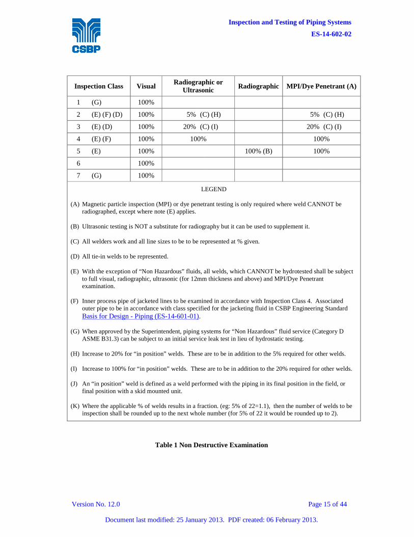
The Contractor’s non-destructive examination (NDE) shall not be less than the percentages shown in Table 1. These percentages shown refer to Shop and Field welds. Additional radiographs on any defective welds or repairs shall be to the Contractor’s account. For welds that are radiographed the weld surface shall be sufficiently smooth to allow for proper evaluation to ASME VIII.
Final non-destructive examination to the minimum required by Table 1, shall be performed after any post weld or post fabrication heat treatment.
The acceptance Standards for the non-destructive examination shall be in accordance with ASME B31.3.
The inspector representing the Superintendent will nominate the specific welds to be radiographed.
For jacketed piping all circumferential and longitudinal welds in the inner pipe shall be 100% radiographed in accordance with Inspection Class 4.
All piping is subject to 100% visual inspection. Visual inspection shall be done before, during and after welding, prior to painting or any other surface treatment.

Inspection and Testing of Piping Systems
ES-14-602-02
Version No. 12.0 Page 14 of 44
Document last modified: 25 January 2013. PDF created: 06 February 2013.
All nozzle welds and structural attachment welds shall be dressed to a reasonably smooth finish, free from undercut and merge smoothly into the pipe surface without any sharp corners or other stress raisers.
The following items shall be checked for compliance with CSBP Engineering Standard Fabrication and Installation of Piping (ES-14-602-01) for all fabrication work:
a. Correct storage of welding consumables.
b. Quality of weld preparation including cleanliness, alignment, preheating, and tack welds.
c. Adequate protection against bad weather conditions.
d. Correct procedures followed during interruptions in welding, especially when preheating is involved or root bead only is deposited.
e. Appearance of weld, including reinforcement and dressing of the weld surface.
f. Quality of welding repairs.
g. Correct heat treatment.
h. Correct gaskets fitted in flanged joints.
i. Correct studs fitted in flanged joints.
j. All flanged joints fully tightened.
Inspection and Testing of Piping Systems
ES-14-602-02
Version No. 12.0 Page 15 of 44
Document last modified: 25 January 2013. PDF created: 06 February 2013.
Inspection Class Visual Radiographic or
Ultrasonic Radiographic MPI/Dye Penetrant (A)
1 (G) 100%
2 (E) (F) (D) 100% 5% (C) (H) 5% (C) (H)
3 (E) (D) 100% 20% (C) (I) 20% (C) (I)
4 (E) (F) 100% 100% 100%
5 (E) 100% 100% (B) 100%
6 100%
7 (G) 100%
LEGEND
(A) Magnetic particle inspection (MPI) or dye penetrant testing is only required where weld CANNOT be radiographed, except where note (E) applies.
(B) Ultrasonic testing is NOT a substitute for radiography but it can be used to supplement it.
(C) All welders work and all line sizes to be to be represented at % given.
(D) All tie-in welds to be represented.
(E) With the exception of “Non Hazardous” fluids, all welds, which CANNOT be hydrotested shall be subject to full visual, radiographic, ultrasonic (for 12mm thickness and above) and MPI/Dye Penetrant examination.
(F) Inner process pipe of jacketed lines to be examined in accordance with Inspection Class 4. Associated outer pipe to be in accordance with class specified for the jacketing fluid in CSBP Engineering Standard Basis for Design - Piping (ES-14-601-01).
(G) When approved by the Superintendent, piping systems for “Non Hazardous” fluid service (Category D ASME B31.3) can be subject to an initial service leak test in lieu of hydrostatic testing.
(H) Increase to 20% for “in position” welds. These are to be in addition to the 5% required for other welds.
(I) Increase to 100% for “in position” welds. These are to be in addition to the 20% required for other welds.
(J) An “in position” weld is defined as a weld performed with the piping in its final position in the field, or final position with a skid mounted unit.
(K) Where the applicable % of welds results in a fraction. (eg: 5% of 22=1.1), then the number of welds to be inspection shall be rounded up to the next whole number (for 5% of 22 it would be rounded up to 2).
Table 1 Non Destructive Examination
Inspection and Testing of Piping Systems
ES-14-602-02
Version No. 12.0 Page 16 of 44
Document last modified: 25 January 2013. PDF created: 06 February 2013.
5.2 BRANCH WELDS AND REINFORCING PADS
Special care shall be taken in the inspection of branch welds, weldolets and reinforcing pad welds. All branches shall be properly fitted to assure the production of sound welds. Branch welds shall merge smoothly with the surface of the pipe with no notches or undercutting permitted. Sharp corners on reinforcing pads shall be removed.
5.3 HARDNESS TESTING
Brinnell hardness testing shall be performed on heat-treated welds in accordance with ASME B31.3, plus as specified in section 4 of Fabrication and Erection of Piping (ES-14-602-01).
Hardness tests are not required on welds for which it is not possible to perform a test.
The acceptance criteria shall be as per ASME B31.3, except that where the code does not specify a criteria (e.g. carbon steel), then the maximum hardness shall be as specified in section 4 of Fabrication and Installation of Piping (ES-14-602-01).
6. STAGE 2 - TESTING
All piping shall be pressure tested except for:
a. Lines and systems which are open to the atmosphere, such as drains, vents, and atmospheric sewers, unless noted otherwise on design documentation
b. Where the Superintendent, Area Plant Engineer, and Senior Plant Inspector have authorised that no test is required. The approval of the pressure testing waiver and the reason for the waiver shall be recorded on the ITP or other quality documentation included in the MDR.
Note: When approved by the Superintendent, piping system for “Non Hazardous” fluid service (Category D ASME B31.3) can be subject to an initial service leak test in lieu of hydrostatic testing.
Pressure testing for metallic piping shall be in accordance with ASME B31.3 and as specified in this Standard. The test pressures shall be as indicated on the piping isometrics/line list.
For non-metallic piping, if a clear comprehensive test method is given in the applicable Australian or international standard for that piping material, or in the manufacturer’s recommendations, then that method may be used instead of parts of the method given in section 6.4. In the absence of any clear alternative method, then ASME B31.3 and section 6.4 shall be followed.
Where approved by the Superintendent, Area Plant Engineer and Senior Plant Inspector, specific requirements of sections 6.1.1 and 6.4 may be relaxed, and the deviations and approval of the deviations recorded on the hydrostatic test record, ITP or other quality record included in the MDR. Examples of some relaxations that may be granted are in 6.4.14.
Non-essential personnel shall be excluded from the immediate test area. Refer Section 4.2.1 for pneumatic test exclusion zones. For hydrostatic test, the following may be used as a guide:
Inspection and Testing of Piping Systems
ES-14-602-02
Version No. 12.0 Page 17 of 44
Document last modified: 25 January 2013. PDF created: 06 February 2013.
• 1m - 150# rated systems,
• 2m - 300#, 600 and 900# rated systems
• 5m - 1500# systems and above.
Note: Unless there is a reason to suspect the condition of the welds or pipe, or the system is 1500# or above the restricted area may be confined to around flanges, valves and other likely leak points.
6.1 PUNCHLISTING PIPING SYSTEMS
6.1.1 Pre-test Punchlisting
Piping systems shall be punchlisted by “test pack” initially in Pre-test format to maintain the pressure testing schedule, and following a successful test of the system a Post-test punchlist shall be issued to the Contractor.
Inspections shall be performed using the Stage 1 Commissioning Inspection Reports described in Section 5 (M146 and M147). Items that are incomplete or unsatisfactory shall be placed on a Pre-test Punchlist.
Atmospheric lines, which cannot be tested, are subjected to a visual examination only, with the relevant parts of the Stage 1 Commissioning Inspection Reports still being inspected and punchlisted. For record purposes, the Pre-test punchlist shall identify all “No Pre-test punch list items”.
The Pre-test punchlist shall confirm that all welding, including welded attachments, has been complete and the system is ready to be pressure tested.
The Superintendent’s Field Supervisor or Fabrication Inspector (nominated by the Superintendent), who shall be responsible for the preparation of the punchlist, shall conduct an inspection of the system after the Contractor has performed their own inspection and advised that the system is ready for testing. Simultaneously, the Contractor’s Quality Manager will satisfy the Superintendent’s Fabrication Inspector that all welding and NDE is complete and that all components meet the traceability requirements of the specification.
The Piping Field Test Report (PFTR), which is the lead sheet in the test pack, provides authorisation for a test to proceed. An example PFTR can be found in APPENDIX 7. It shall not be signed off until all pre-test punch list items have been cleared, all NDE is complete and the Stage 1 Commissioning Inspection Reports are complete.
Contractor is to confirm the following:
a. The Fabrication Inspector(s) has cleared all NDT/Traceability records and the Test Pack has been signed accordingly.
b. All pre-test punch list items have been completed and the Test Pack signed off.
c. The latest revision of isometrics are included in the Test Pack.
d. Correct thickness of test spades, blinds and gaskets are installed.
Inspection and Testing of Piping Systems
ES-14-602-02
Version No. 12.0 Page 18 of 44
Document last modified: 25 January 2013. PDF created: 06 February 2013.
e. Test pressure gauges have been calibrated and correctly installed.
f. Calibration certificates for test gauges and relief valves are current.
g. Lock spring supports if the test medium has a different density to the fluid in the piping in normal operation.
h. All inline instruments have been removed (except thermowells) and signal and impulse lines disconnected.
i. All vents, drains and primary instrument connections have been plugged / capped and all valves are open.
j. All control valves have been removed and stored in a safe location with flange faces protected.
k. All equipment has been spaded off and precautions taken to ensure that test or flushing water cannot enter equipment. (especially compressors) Testing through equipment is by exception only.
l. All relief valves have been spaded off or removed to a safe location with flange faces protected.
m. Pneumatic test access barriers are in place and the Superintendent’s Safety Department notified.
A test may not proceed until both the Superintendent’s Fabrication Inspector and Piping/Mechanical Engineer have signed the PFTR.
In addition to notification in the Inspection and Test Plan, the Contractor shall advise the Superintendent of test by making entry in Inspection and Testing Log Book a minimum of forty-eight hours prior to hydrotest and five working days in the case of a pneumatic test. Refer to APPENDIX 6 for example Inspection and Testing Log Book.
6.1.2 Post Test Punchlisting and Reinstatement Pack
Post test punch listing is a complete and comprehensive review of each piping system.
Following successful testing, the Contractor shall reinstate piping systems by removing test spades/blinds etc. and re-instate all in-line instruments and valves. The Superintendent shall then prepare a Post Test Punch List and submit this to the Contractor for prompt execution.
The punchlist shall be prepared by examining the piping system against the Stage 2 Commissioning Reports: Pipelines (M246) and Pipeline Valve Operation (M247). To supplement the Stage 2 Commissioning Reports, the Contractor shall prepare a reinstatement pack to go with every test pack, or piping system where piping is not hydrostatically or pneumatically tested. The reinstatement pack is to be checked during the Stage 2 commissioning report inspections. The reinstatement pack shall consist of:
a. Copies of test pack drawings highlighting spade, blank and plug locations, removed items, correct flow direction for unidirectional items, and other special items or actions, which need to be removed, installed or performed to ensure correct reinstatement of the piping system.
b. Copies of drawings and documents showing support locations and details.
Inspection and Testing of Piping Systems
ES-14-602-02
Version No. 12.0 Page 19 of 44
Document last modified: 25 January 2013. PDF created: 06 February 2013.
c. A list of special items which may not be obvious to the person reinstating the piping system. Such items may include:
1. Reinstallation of thermowells.
2. Reinstallation of internals of items such as non-return valves and steam traps.
3. Noting of drilling of ball or plug valves and which end the hole should be.
4. Checking of pipe support guide clearances.
5. Removal of spring support locks/chocks.
6. Post commissioning spring support hot set check and adjustments.
Where there is no test pack for a piping system, then a reinstatement pack shall still be prepared using the latest revision of the piping drawings to check that the final installation is correct.
Reinstallation packs shall be submitted for approval to the Superintendent
The Contractor shall maintain a record of testing and provide a weekly report indicating the number of post test punchlists issued, total number of punchlist items, how many were cleared in the last week and total number outstanding.
An example Piping Test Pack Index can be found in APPENDIX 5.
The Contractor shall supply a copy of all calibration certificates for the Master Test Pack. Gauges shall be inspected for defects and to ensure proper working order. Contractor shall have available a range of test gauges to cover all test pressure requirements within his scope of work.
A chart pressure recorder and temperature recorder shall be used for all pneumatic tests. The original chart record of pressure versus time, and temperature versus time shall be included in the Master Test Pack. Unless otherwise agreed by the Superintendent a chart recorder shall be used for hydrostatic tests.
6.2 SYSTEM FLUSHING
All lines and attached equipment shall be thoroughly flushed and cleaned with the testing medium, before testing takes place.
Pipework shall have the inlet located at the highest point such that each branch is thoroughly flushed. On large and diverse systems, several return lines to the tanker may be necessary.
The Contractor shall furnish and install flushing screens (temporary strainers) on the upstream side of all equipment. After flushing, items shall be removed and all resulting debris removed from the work site by the Contractor.
The Superintendent shall be the sole judge of the cleanliness of the piping system.
Volume of water for flushing shall be sufficient to provide a continuous flow for at least fifteen minutes. High volume low-pressure pumps shall be employed to ensure that any debris within the lines is removed.
Inspection and Testing of Piping Systems
ES-14-602-02
Version No. 12.0 Page 20 of 44
Document last modified: 25 January 2013. PDF created: 06 February 2013.
Flushing by air shall be subject to approval by the Superintendent. Where used, except as defined in Section 6.9, Contractor shall ensure that volume is sufficient to blow out any debris. Exit locations for air blowing shall be chosen to ensure safety of personnel and consideration shall be given to the noise emitted during this activity.
6.3 WITNESSING PIPING SYSTEM PRESSURE TESTING
6.3.1 Request to Witness a Test
In addition to notification in the Inspection and Test Plan, the Contractor shall make an entry in the “Inspection and Testing Log Book” at least 48 hours before a hydrotest and at least five (5) days before a pneumatic test.
An example of the Inspection and Testing Log Book can be found in APPENDIX 6.
6.3.2 Witnessing a Pressure test
Following acceptance of line flushing, Contractor shall reconfigure system for a pressure test. Hydrotests shall be filled from low point, with high point vents opened to allow air to escape.
During a hydrotest, the immediate area shall be isolated using bunting, which carries a safety warning and advises that a pressure test is being conducted. Refer to Section 6 for guidelines on exclusion distances.
Pneumatic tests require an exclusion zone, refer Section 6.7. The Contractor shall schedule pneumatic tests to ensure that the exclusion zone is kept clear of all personnel during system pressurisation and only those personnel directly involved with the test may enter to conduct and witness the soap tests at designated “hold” periods.
Contractor shall provide safe access to every weld / screwed connection for the Superintendent’s Inspector.
All pressure tests shall be witnessed by an approved NATA endorsed Inspector and by the Superintendent, at his discretion.
Following examination and acceptance of the system, the recorder charts and the PTFR in the Master Test Pack shall be signed off.
Within 24 hours, Contractor shall bind original charts, and copies of all relevant calibration certificates together with any other pertinent documentation into the Master Test Pack.
6.4 HYDROSTATIC TESTING
6.4.1 Equipment
The Contractor shall supply and install all necessary equipment and materials necessary to pressurise and test the pipework and associated equipment.
The equipment, controls, instruments, etc, used in conducting pressure tests shall be in good repair and of a kind and type acceptable to the Superintendent.
Inspection and Testing of Piping Systems
ES-14-602-02
Version No. 12.0 Page 21 of 44
Document last modified: 25 January 2013. PDF created: 06 February 2013.
Continuous pressure and temperature recorders shall be supplied by the Contractor and used to record pressure and temperature during the test period.
Equipment to be used during testing shall have suitable capacity for the range of test pressures required. Pressure indicators shall have a full-scale range between 110 percent and 150 percent of test pressure and an accuracy and sensitivity of 2 percent of full-scale reading. All pressure gauges and chart recorders shall have current calibration certificates endorsed by a NATA approved authority.
A minimum of two gauges shall be provided for each test system. One shall be located at the highest point and one located at the pump at grade. A gauge shall also be located at the extremity of each system unless otherwise agreed by the Superintendent.
6.4.2 Contractor Obligations
The Contractor shall submit comprehensive testing procedures and schedules both for hydrostatic and pneumatic testing, to the Superintendent for his approval prior to start of testing.
It is the Contractor’s responsibility to satisfy the Superintendent that procedures will not result in any damage or deformity to the piping or the equipment and they incorporate all safety requirements.
Approval of the procedure by the Superintendent does not absolve the Contractor from the responsibility of workmanship, quality compliance with the Code requirements and safety considerations.
The Contractor shall review drawings and pipework prior to pressure testing to ensure that sufficient vents, drains, blind flanges, etc, are installed to carry out the hydrostatic testing procedures. All high points must be vented and low points capable of being drained. The Contractor shall provide any additional vents and drains that are required in accordance with the applicable piping specification.
Any errors, discrepancies or omissions on the drawings shall not relieve the Contractor of the responsibility for pressure testing the pipework in accordance with the intent of this Standard. Any such error, discrepancy or omission shall be brought to the attention of the Superintendent for an interpretation or ruling.
6.4.3 Equipment Isolation
Equipment such as pumps, compressors, blowers, turbines, other rotating machinery and vessels, heat exchanges, columns, etc, shall be isolated from the pressure test. Spades shall be installed at the flanges of the equipment to provide positive isolation prior to filling up the system.
Expansion bellows and spring supports shall be restrained or removed during hydrostatic testing. Each case shall be referred to the Superintendent for direction prior to testing.
All restrictions that would interfere with filling, venting or draining, such as orifice plates and flow nozzles, shall not be installed until testing is completed. Suitable spacers shall be installed for testing.
Inspection and Testing of Piping Systems
ES-14-602-02
Version No. 12.0 Page 22 of 44
Document last modified: 25 January 2013. PDF created: 06 February 2013.
Piping shall be tested prior to installation of inline items such as relief valves, control valves, rupture discs, displacement and turbine meters, orifice plates, flow nozzles, level gauges, rotameters, strainers, etc, or the connection of instruments to the piping system to be tested. If it is not practicable to perform testing prior to installation of inline items, it shall be Contractor’s responsibility to remove or disconnect these items so those tests can be performed and to re-install such items after testing. Sealing and plugging for testing of systems after removal of inline items shall be performed by contractor. Contractor shall remove sealing and plugging items after completion of testing and shall re-install the inline items.
6.4.4 Valve Configuration
The operation, settings and ratings of all safety valves/relief valves and rupture discs shall be checked and tested in accordance with ASME B31.3.
All gate, globe and butterfly valves shall be tested in the open position unless otherwise specified on the piping isometric. Ball valves shall be tested in the half-open position.
Piping containing check valves shall have the pressure source located on the upstream side of the valve and the drain on the downstream side of the valve. Where this is not possible, check valve internals shall be removed for testing. A new gasket shall be installed if the valve bonnet has been removed after completion of testing.
6.4.5 Joints
All joints in the piping system shall be accessible during tests and shall not be insulated, back-filled or otherwise covered until satisfactory completion of testing in accordance with this Standard. Any protective tape applied to shop welds in carbon steel spools shall be removed prior to pressure testing.
The breaking of joints to insert blanks for testing should be kept to a minimum.
Sealing materials shall not be used to correct leaks at joints. Valve glands shall not be tightened to the extent that the valve cannot be operated. If directed by the Superintendent valves shall be repacked.
6.4.6 Loading Considerations
Care shall be taken to avoid overloading any part of the pipe support system or supporting structures. Large piping designed for vapour or gas shall be provided with additional temporary supports, if necessary, to support the weight of the test fluid.
Large adjacent lines shall not be tested simultaneously if the weight of the combined tests may overload the structure or supports.
6.4.7 Field Installed Reinforcing Pads
The Contractor shall test all field installed reinforcing pads with dry air at 35kPa gauge (5psig). All weld surfaces shall be swabbed with a leak testing solution approved by the Superintendent. After testing is complete the vent hole shall be plugged with grease or with approved plastic plugs. The Contractor shall maintain a record of all reinforcing pad tests.
Inspection and Testing of Piping Systems
ES-14-602-02
Version No. 12.0 Page 23 of 44
Document last modified: 25 January 2013. PDF created: 06 February 2013.
6.4.8 Steam Jacketing
The jacket of jacketed lines shall be tested as described in ASME B31.3. If the test pressure in the jacket is too high for the internal lines as an external pressure, the internal line shall be pressurised to minimise the differential pressure.
6.4.9 Venting
The Contractor shall be responsible for the venting of all sections of the piping system and shall make every effort to ensure removal of trapped air to the satisfaction of the Superintendent.
6.4.10 Testing Medium
For hydrostatic testing of carbon steel piping systems the test medium shall be potable water at ambient temperature with pH value between 6 and 7.
For hydrostatic testing of piping systems that are wholly or partially fabricated from austenitic stainless steel piping components the test medium shall be demineralised water with a chloride content of maximum 1 ppm and pH value between 6 and 7. Water shall be drained immediately after hydrostatic testing.
A report on water analysis including the chloride content and pH value of the water shall be attached to the test report at all times when austenitic stainless steel systems are hydrotested. A certified and recognised laboratory shall prepare the analysis and report.
6.4.11 Test Pressure
In accordance with ASME B31.3 the minimum hydrostatic test pressure at any point in the system shall be:
a. 1.5 times the design pressure, or
b. calculated in accordance with formula specified in ASME B31.3 if the design temperature is above the test temperature.
The test pressure for non-metallic piping shall be in accordance with the piping manufacturer’s recommendations and the applicable Australian or international standard covering installation and testing of the piping material
6.4.12 Test Duration
Pipework shall be observed continuously during all filling and testing operations.
Minimum duration of hydrostatic test from the time the pressure has been obtained with no leaks shall be:
a. 30 minutes for pipework where:
1. All sections of the pipe are visible.
2. The pipe is easy to inspect.
3. Volume is relatively small.
4. System of pipework being tested is relatively short and simple.
Inspection and Testing of Piping Systems
ES-14-602-02
Version No. 12.0 Page 24 of 44
Document last modified: 25 January 2013. PDF created: 06 February 2013.
b. One (1) hour for pipework where:
1. Not all sections of the pipework are visible.
2. The pipe is not easy to inspect.
3. Volume is relatively large.
4. System of pipework being tested is long and complex.
5. Extra thick walled pipe is being tested.
c. As determined and specified by the Superintendent to suit any circumstances but not less than ‘a’ or ‘b’ above.
6.4.13 Rectification
The Contractor shall be responsible for rectification work of damage, resulting from test pressures being more than ten (10) percent higher than those specified on the Piping Isometrics and Line List.
6.4.14 Examples of Hydrostatic Testing Dispensations That May be Approved
Refer to the beginning of Section 6 for approval of these dispensations and what needs to be recorded.
The following examples of dispensations that might be granted, only apply to work covered by, Repairs and Minor Alterations to Existing Pressure Equipment, Piping and Tanks (DP-05-095-06).
1. One test gauge is allowable as long as it is located so it will measure the maximum pressure in the system during the test.
2. A chart is not recorded as long as the test gauge reading/s are witnessed by the inspector at the start and the end of the test, and if the duration is longer than 30 minutes, then at least once every 30 minutes.
3. If the flange rating is 150# or less, the fluid is not a class 2 or 3 hazardous fluid under, Breaking into Hazardous Pipelines (GM-11-036-02), then the following dispensations may be considered:
(a) A standard gauge that has been calibrated within a month of the test may be used in lieu of a NATA certified gauge. The calibration certificate shall be included with the test pack in the MDR.
(b) The requirement for a NATA certified inspector may be waived as long as the test is witnessed by the Superintendent’s nominated representative (eg piping inspector, field supervisor).
4. For systems with flanges rated up to 300#, where it is difficult to fully spade off the test system due to factors such as welded in valves and/or lack of available shutdown time, tests may be done using valves as isolation.
5. On insulated lines only new, modified or repaired piping, valves and fittings need to be uninsulated for the test for the purposes of inspection.
Inspection and Testing of Piping Systems
ES-14-602-02
Version No. 12.0 Page 25 of 44
Document last modified: 25 January 2013. PDF created: 06 February 2013.
6. If parts of a line are not accessible without setting up special access such as scaffolding, then only new, modified or repaired piping, valves and fittings need to be made accessible for the test for purposes of inspection.
7. If the pressure during a hydrostatic test cannot be maintained due to a pre-existing passing or leaking valve or fitting, or an inability to fully vent the system, then the test may be passed by continually pumping up the system to test pressure and inspecting the area of new work for leaks. The Superintendent should perform an assessment of any leaks from existing valves and fittings to see if maintenance rectification work is required. The Superintendent shall arrange for rectification of leaks or passing from new items.
8. Water analysis for water used for hydrostatic tests of austenitic stainless steel lines is not required if CSBP site supplied demineralised water is used.
6.5 SYSTEM DRYING
After hydrostatic testing of the system is complete and approved, all lines and equipment shall be completely drained of the test fluid. Piping systems vents shall be opened while draining to avoid vacuum. Special attention shall be given to points where water may be trapped, such as in valve bodies or low points.
An air compressor designed to deliver high volume dry air shall be connected to the system high point(s). Air shall be blown continuously until all water has been driven out and the Superintendent accepts the system.
The only exception to this requirement shall be cement-lined pipe, which must be kept in a wet condition to prevent deterioration of the lining, or if the Superintendent advises that air-drying is unnecessary. An example of when the Superintendent may advise that air-drying is unnecessary is when the fluid to flow through the piping is compatible with water, the water is not going to effect any equipment supplied through the piping, and the line is unlikely to suffer from oxygen/water corrosion between the test and when it is commissioned (e.g. stainless steel lines, very short time period between end of test and commissioning for carbon steel lines).
6.6 CHEMICAL CLEANING OF PIPING SYSTEMS
Chemical cleaning shall not be considered a substitute for line flushing and shall only be performed where specified by the Superintendent. Where a piping system is to be chemically cleaned it shall have previously been flushed, tested and blown dry. Drying may be deferred only if chemical cleaning is to immediately follow a hydrotest.
The Superintendent shall approve any Company undertaking chemical cleaning of pipework.
Unless otherwise specified the chemical solution shall be a solution of Citric Acid and Ammonia. (Ammonium Citrate degreasing and cleaning solution).
Batch mix a citric acid powder in water to achieve a 3% (weight/volume) solution, adding 0.2% Surfactant and 0.2% Wetting Agent Detergent. This shall be neutralised with ammonia to a pH of 3 to 3.5, either before putting into the system, or during initial circulation.
Inspection and Testing of Piping Systems
ES-14-602-02
Version No. 12.0 Page 26 of 44
Document last modified: 25 January 2013. PDF created: 06 February 2013.
Fill system with this solution and circulate for a minimum of eight (8) hours. Sample every hour, test and record for:
Iron (FE++) Concentration : (Ferrous Iron Pick-up parts per million) Acid Concentration : (Percent Weight/Volume) pH : (Using pH meter)
Iron pick-up will depend upon the condition of the pipework but should fall within a range of 600 to 2500ppm.
Acid concentration shall not be allowed to fall below 2% weight/volume.
Circulation shall continue until the test results stabilise. Acceptance criteria, for carbon steel pipe is as follows:
Ferrous Iron Pick-up : Minimum 600ppm Optimum 1500ppm Maximum 2500ppm Acid Concentration : Minimum 2% weight/volume Optimum 3% weight/volume Maximum 4% weight/volume
Results of all samples taken shall be recorded and the results filed in the Master Test Pack.
6.7 PNEUMATIC TEST PROCEDURES
Pneumatic testing of piping systems involves the potential hazard of released stored energy in compressed gas and should therefore only be considered when alternative testing procedures can not be used. Refer to APPENDIX 4 for example authorisation to test through a vessel form.
Any system which has been nominated for pneumatic testing shall be carried out in accordance with ASME B31.3 with special consideration given to safety during testing including the setting up of exclusion zones (calculated as per Appendix D of AS3788)
Specific procedures will be developed on a project basis relevant to the system being testing, by the Contractor in liaison with the Superintendent. The procedure shall require final approval by the Superintendent before being implemented.
Duplicate, high integrity, pressure gauges shall be fitted to the system under test.
6.8 LEAK TESTING OF PIPING SYSTEMS
During the testing stage and just prior to start-up, selected systems such as ammonia, chlorine and other toxic, flammable and corrosive fluids shall be checked for tightness. Three procedures are available as follows:
a. Soap and Bubble Leak Test.
This test is applicable for hazardous fluid systems 600# rating and above.
b. Nitrogen/Helium Leak Test.
Inspection and Testing of Piping Systems
ES-14-602-02
Version No. 12.0 Page 27 of 44
Document last modified: 25 January 2013. PDF created: 06 February 2013.
This test is applicable for ‘extreme toxic danger’ fluid systems.
c. Simplified Leak Test.
This is applicable to non-hazardous fluid systems and for hazardous fluid systems with 150# and 300# rating. Refer to Section 6.8.8 for details.
The Soap and Bubble Leak test shall be used unless otherwise specified or approved by the Superintendent.
The systems to be leak tested shall have previously been hydrostatically or pneumatically tested in accordance with the Code, and therefore all welded joints have been proved sound. The leak test is limited to flanged joints (including vessels), valve glands and instrument connections.
In liaison with the Superintendent, the Contractor shall write a Project specific procedure.
The procedure shall require final approval by the Superintendent before being implemented. The following guidelines shall apply:
6.8.1 Setting Up
The individual procedure for each leak test shall describe in detail the work required to make the system ready. This procedure should be strictly adhered to.
6.8.2 Workmanship
Contractor personnel and operators of plant and equipment shall be competent, experienced persons holding current licenses and trade qualifications/certificates commensurate with the work.
6.8.3 Preparation for Testing
All preparatory work associated with the system to be leak-tested, shall be carried out by the Superintendent’s personnel, including:
a. opening all inline manually operated valves
b. opening all inline actuated valves
c. opening all instrument tapping valves
d. taping all flanged joints with duct sealing tape and putting pinhole in tape.
e. identifying purge points and opening vent valves
f. determining test exclusion zone and erecting suitable barriers.
The Contractor shall set up his equipment and prior to connection to the system fill point(s), shall blow his manifold and connecting hose(s) to ensure that they are clean.
Inspection and Testing of Piping Systems
ES-14-602-02
Version No. 12.0 Page 28 of 44
Document last modified: 25 January 2013. PDF created: 06 February 2013.
A pre test inspection of the system shall be carried out jointly with the Superintendent to ensure that all preparatory work has been completed, the system is ready to be tested and the test equipment has been set up correctly.
6.8.4 Test Procedure
Purging gas will be:
a. Dry air or nitrogen for Soap and Bubble Test or,
b. Nitrogen/helium mix.
Commence purging system, ensuring that any specified gas mix is within the specified range. During the purging operation the vent valves shall be progressively closed as purging gas is detected.
Note: If dry air is used, vent valves can be closed prior to purging.
When all vent valves have been closed commence pressuring the system as follows:
a. Increase pressure gradually to an initial pressure of 170kPa(g) and hold for a minimum of ten (10) minutes.
b. Examine all flanged joints, valve glands and other connections where there is a potential for leakage using:
1. A gas spectrometer or other approved method for Nitrogen/Helium Leak Test, or
2. Soapy water or other approved leak testing solution applied to the outside surface of test area.
Should any leaks be observed, the Contractor shall arrange rectification. This may be done while the test is in progress with the leak rechecked after at least 15 minutes.
c. Pressure in the system shall be increased to 500kPa and held for five (5) minutes. Thereafter the pressure shall be increased in 500kPa increments to the specified test pressure, with a five (5) minute holding period after each step.
d. When the test pressure has been attained it shall be held for a minimum of one (1) hour or as directed by the Superintendent, during which time the test gauges shall be closely monitored. Following this hold period the final check for leaks shall be conducted as described above.
When all tests are complete, the system shall be de-pressured.
Note: Pressuring/de-pressuring rate shall not result in a differential pressure of more than 10kPa across the internals of any vessel within the test; or 100kPa/minute - whichever is the more stringent.
Inspection and Testing of Piping Systems
ES-14-602-02
Version No. 12.0 Page 29 of 44
Document last modified: 25 January 2013. PDF created: 06 February 2013.
6.8.5 Test Records
The Superintendent shall prepare a ‘Test Pack’ for each system to be tested. Upon successful completion of each test a certificate contained therein shall be signed by the Contractor and by the Superintendent’s commissioning engineer.
Contractor shall provide pressure gauge calibration certificates for inclusion in the test pack.

Inspection and Testing of Piping Systems
ES-14-602-02
Version No. 12.0 Page 30 of 44
Document last modified: 25 January 2013. PDF created: 06 February 2013.
6.8.6 Test Equipment
The Contractor shall supply test equipment. As an example, the minimum for a Nitrogen/Helium Leak Test is:
a. Bottled nitrogen with standard valve, regulator and pressure indicator,
b. Bottled helium with standard valve, regulator and pressure indicator,
c. Calibrated measuring equipment and associated valves to provide a 2% - 3% (by volume) helium in nitrogen mixture,
d. Pressure gauges,
e. Provision for a chart recorder,
f. Provision for relief valve,
g. Relieving vent with double block and bleed valve,
h. Isolation double block and bleed valves,
i. Portable test bench incorporating test manifold assembly, and
j. Pressure hose(s).
6.8.7 Pressure Gauges
Pressure gauges shall have an operating range, such that the test pressure is between 40% and 75% of the indicated range for each instrument and shall conform to AS 1349 - 1973 (minimum nominal gauge size - 100mm). The two gauges shall be similar, and test calibrated and certified by a NATA approved laboratory not more than three months before the date of the test.
Every instrument and gauge shall display an identification label which shall state the date when last tested and the order of accuracy over the range of the instrument.
Both gauges shall be visible to the operator controlling the test pressure.
6.8.8 Flow Measurement
The devices used to measure gas flow rates shall be calibrated to ensure that the required gas volumes are maintained.
6.8.9 Simplified Leak test Procedure
Where approved by the Superintendent, the leak test may be simplified as follows:
a. After the first hold period, the pressure may be slowly taken straight up to the final test pressure.
b. Hold at final pressure to be reduced to 30 minutes.
c. Detection of leaks shall be primarily by visual examination. However a local pressure gauge or transmitter shall also be used to monitor pressure during the test to look for evidence of leaks.
d. No NATA certified test gauges or charts are required.
Inspection and Testing of Piping Systems
ES-14-602-02
Version No. 12.0 Page 31 of 44
Document last modified: 25 January 2013. PDF created: 06 February 2013.
e. A calibrated gauge will be required where the air or nitrogen source could provide pressures higher than the piping design pressure. This gauge will be used to monitor pressure to ensure the piping system is not over-pressurised.
f. No flow monitoring is required.
g. Records kept shall be limited to recording which lines were checked and whether there were any leaks left at the end of the test.
6.9 AIR BLOWING OF PROCESS PIPEWORK
Where air blowing is specified to provide a clean environment for the product at start-up, a Project specific procedure shall be written by the Contractor in liaison with the Superintendent, in a format similar to APPENDIX 2. The procedure shall require final approval by the Superintendent before being implemented. The following guidelines shall apply:
6.9.1 Duration of Air Blow
Each system shall be blown against a target plate for a minimum duration of two hours.
6.9.2 Location of Target Plates
Target plates shall be located as specified in the system narrative; however the Contractor shall ensure that exiting airflow does not constitute a safety hazard.
6.9.3 Air Flow Requirements
Airflow will be approximately 150% of normal operating velocity. This will be achieved by sizing the gap at each exit point. (i.e. between the flange and target plate).
6.9.4 Re-instatement
Upon completion of each air blow, Contractor shall reconfigure system as described in the procedure, and upon final completion, reinstate system in accordance with the drawings and as directed by the Superintendent.
6.9.5 Compressor
This procedure assumes that the Compressor is an integral component in the process stream and is to be used to provide driving air for the air blowing process. If a temporary unit is brought in to provide driving air, the company from whom the unit is hired shall provide the pre start-up checklist.
6.9.5.1 Pre Start-up Checklist
Prior to start-up the following items/systems shall be commissioned and ready for service:
a. Compressor inlet ductwork,
b. Any compressor inter-stage pipework has been manually cleaned,
c. Lube and seal oil systems,
d. Non-drive motors to be uncoupled,
Inspection and Testing of Piping Systems
ES-14-602-02
Version No. 12.0 Page 32 of 44
Document last modified: 25 January 2013. PDF created: 06 February 2013.
e. Steam supply to turbine from battery limit (also impacted by Steam blowing) if compressor steam turbine driven,
f. LP Steam supply to seals if compressor steam turbine driven,
g. Cooling Water to any consumers associated with the compressor, and
h. Instrument Air.
Additionally, power shall be available to drive the oil pumps and the compressor motor.
6.9.6 Start-up and Operating Procedures
Prior to starting the compressor for air blowing, all Manufacturers nominated trials shall have been completed.
Start up and operation of the compressor shall be in accordance with Manufacturers procedures and shall be carried out by CSBP personnel, under the supervision of the Manufacturer’s Commissioning Engineer.
6.9.7 Control Systems
Control systems for the compressor shall be completed and commissioned such that the compressor is capable of running under manual control for the purposes of air blowing, however, the control system shall be available for the compressor and any flow measuring instruments in the systems to be blown.
6.9.8 Target Plate Assemblies/Details
Target plates shall resemble a blind flange and shall be capable of being bolted to the pipe or vessel flange. In order to achieve correct blowing velocity the gap between flange and target plate must be adjustable. This can be achieved by employing extra long bolts and additional nuts to capture and positively locate the target plate in respect to the flange to which it is bolted.
Target plate shall be painted white.
The Contractor shall provide details of proposed target plate assemblies and number of assemblies/plates required, for the Superintendent’s acceptance prior to manufacture.
Additional materials required for air blowing are listed in each of the air blow procedures. Contractor shall review the procedures and determine actual quantities required to complete air blows within the schedule without duplication of materials.
Notwithstanding, Contractor shall be responsible for the supply of all materials and consumables necessary to complete the air-blowing activities in the specified timeframe.
If the Contractor identifies any discrepancies in the materials listed the Superintendent shall be notified accordingly.
6.10 STEAM BLOWING OF TURBINE PIPEWORK
During the testing stage the lines supplying steam to steam turbines and ancillaries shall be blown with steam to prove the cleanliness of the system and to prevent potential turbine damage at start-
Inspection and Testing of Piping Systems
ES-14-602-02
Version No. 12.0 Page 33 of 44
Document last modified: 25 January 2013. PDF created: 06 February 2013.
up. Steam, shall be blown through the piping system via strategically located exit points, moving progressively through the plant. A Project specific procedure shall be written by the Contractor in liaison with the Superintendent in a format similar to APPENDIX 3. The procedure shall require final approval by the Superintendent before being implemented. The following guidelines shall apply:
6.10.1 Setting Up
The individual procedure for each Steam Blow shall describe in detail the work required to make the system ready for a blow. This procedure should be strictly adhered to.
6.10.2 Duration of Blow
Each system shall be blown against a target plate until line temperature is as high as possible. The target plate shall then be inspected, and replaced and the system allowed to cool down to 150°C. before steam blowing continues. This process shall continue until acceptance criteria are reached.
6.10.3 Acceptance Criteria
Two (2) consecutive blowing operations shall provide values not exceeding:
Copper or Aluminium Target Plates
• A maximum indentation of 0.2mm diameter per cm2, and
• five (5) indentations 0.1mm diameter per 20cm2 .
Stainless Steel Target Plates
• A maximum indentation of 0.1mm diameter per cm2, and
• five (5) indentations 0.1mm diameter per 20cm2 .
6.10.4 Location of Target Plates
Target plates shall be located as specified in the system narrative; however Contractor shall ensure that exiting steam flow does not constitute a safety hazard.
Steam Flow Requirements
This shall be in accordance with the turbine manufacturer’s recommendations, and would typically be sufficient steam to generate a velocity 1.5 times normal operating velocity. However, the steam flow may have to be a compromise if there is a limit on steam availability for steam blowing.
6.10.5 Re-instatement
Upon completion of each steam blow, Contractor shall reconfigure system as described in the procedure and upon final completion; reinstate system in accordance with the drawings and as directed by the Superintendent.
Inspection and Testing of Piping Systems
ES-14-602-02
Version No. 12.0 Page 34 of 44
Document last modified: 25 January 2013. PDF created: 06 February 2013.
6.10.6 Target Plate Assemblies/Details
Target plate assemblies shall be constructed such that the plate is easily removable and the assembly shall be capable of being bolted to the pipe or vessel flange at 45° to the axis of the flange.
Target plate shall be sized to present an impingement area greater than the flange it is bolted to.
The final blows shall be made against a polished stainless steel, copper or aluminium plate, however initial blow(s) may be made against a painted plate (preferably white).
Contractor shall provide details of proposed target plate assemblies and number of assemblies/plates required, for the Superintendent’s acceptance prior to manufacture.
6.11 SETTING SPRING PIPE SUPPORTS
Pipe Support Index will specify “set”, “cold” and “operating” condition for spring supports. Supports should be purchased accordingly. In general terms no adjustment to the spring setting should be required, however the Manufacturers’ installation procedure shall be strictly adhered to and the following checks should be made:
6.11.1 Check Support Range
Check that the support is within the range specified in the pipe support schedule.
6.11.2 Setting of the Support
Adjust the support such that the “shipping tabs” can be easily removed, and following hydrotest and complete reinstatement of the system, remove the shipping tabs.
6.11.3 Check for Cold Set and Line Deformation
With the shipping tabs removed, ensure that the line does not sag or lift, the support does not deform the structure upon which it is resting and that the spring support has moved to the correct (cold) position on the scale indicator.
6.11.4 Check Hot Set Position
Check that the support indicator has moved to its operating condition after start-up.
6.12 RE-INSTATEMENT OF PIPING SYSTEMS
Piping systems, which are partially disassembled during testing, re-assembly and re-instatement of the system, shall be subjected to a final check using the Stage 2 Commissioning Inspection Reports and reinstatement pack detailed in 6.1.2, to ensure that system integrity has not been compromised. The P&ID’s shall be used in conjunction with isometrics and pipe support drawings to ensure that reinstatement is complete. See section 6.1.2 on post test punchlisting for checks to be performed after reinstatement of piping systems.
If Operations personnel have not been involved prior to this point it is recommended that they carry out or assist in these checks to provide a degree of Plant familiarisation.
Inspection and Testing of Piping Systems
ES-14-602-02
Version No. 12.0 Page 35 of 44
Document last modified: 25 January 2013. PDF created: 06 February 2013.
6.13 NITROGEN PURGING
Piping in ammonia and flammable gas service, and any other service specified by the Superintendent, shall be nitrogen purged after final re-instatement and before commissioning. This can be combined with leak testing if practical.
Nitrogen shall be fed into the line as close to one end of the piping as practical and vented as close to the other end as possible. The aim is to purge out as much of the air in the piping system as possible. If this is not possible, then the system shall be pressurised with nitrogen to approximately 1000 kPag and then depressurised to atmosphere at least 3 times.
Nitrogen purging shall continue until either a specified target oxygen level is reached in the vented nitrogen, or until the Superintendent advises that the purging can stop.
The Contractor in liaison with the Superintendent shall develop the procedure for nitrogen purging. The Superintendent shall approve the procedure prior to implementation.
The Contractor will supply nitrogen if it is not available locally.
6.14 PIPING TIE-INS TO EXISTING PLANT
Project specific procedures (both operational and safety) shall be written by the Contractor and approved by the Superintendent, however interconnection with the existing Plant shall be progressive during the final phase of Construction as the services are required. As each system is “hooked up” the system shall be designated “live” and identified accordingly.
All work on a live system shall be carried out in accordance with CSBP’s “permit to work system” (see Work Permit System GM-11-031-51) and applicable safety procedures and guides (in particular Breaking Into Hazardous Toxic Substance Pipelines GM-11-036-02), and shall be controlled by the Commissioning Manager.
The Contractor shall include information in his Tool Box Safety Meetings for the construction workforce regarding identification of live (commissioned) systems during the construction phase.
With the exception of “Non Hazardous” fluid service piping systems (Category D ASME B31.3), all tie-in welds which cannot be hydrotested shall be subject to full visual, radiographic and MPI/dye penetrant examination. Refer to Section 5.1 for non-destructive examination details.
6.15 POST COMMISSIONING CHECKS
The Field Supervisor and / or Plant Operating personnel shall perform a post commissioning in service leak check. Any leaks detected shall be referred to the Piping Contractor for rectification.
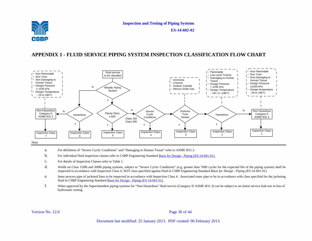
Inspection and Testing of Piping Systems
ES-14-602-02
Version No. 12.0 Page 36 of 44
Document last modified: 25 January 2013. PDF created: 06 February 2013.
APPENDIX 1 - FLUID SERVICE PIPING SYSTEM INSPECTION CLASSIFICATION FLOW CHART
Note
a. For definition of “Severe Cyclic Conditions” and “Damaging to Human Tissue” refer to ASME B31.3.
b. For individual fluid inspection classes refer to CSBP Engineering Standard Basis for Design - Piping (ES-14-601-01).
c. For details of Inspection Classes refer to Table 1.
d. Welds on Class 150lb and 300lb piping systems, subject to “Severe Cyclic Conditions” (e.g. greater than 7000 cycles for the expected life of the piping system) shall be inspected in accordance with Inspection Class 4, NOT class specified against fluid in CSBP Engineering Standard Basis for Design - Piping (ES-14-601-01).
e. Inner process pipe of jacketed lines to be inspected in accordance with Inspection Class 4. Associated outer pipe to be in accordance with class specified for the jacketing fluid in CSBP Engineering Standard Basis for Design - Piping (ES-14-601-01).
f. When approved by the Superintendent piping systems for “Non Hazardous” fluid service (Category D ASME B31.3) can be subject to an initial service leak test in lieu of hydrostatic testing.
• Non Flammable • Non Toxic • Non Damaging to
Human Tissue • Design Pressure
≤ 1035 kPa • Design Temperature
– 29 to 186°C
Non Hazardous Category D
ASME B31.3
Inspection Class 7
Hazardous
Inspection Class 6
Fluid service to be classified
Metallic Piping System
Piping Class
≥ 600
Inspection Class 5
Severe Cyclic
Conditions
Inspection Class 4
Extreme Toxic
Danger
Hazardous
Inspection Class 3
Inspection Class 2
• Ammonia • Chlorine • Sodium Cyanide • Nitrous Oxide Gas
• Flammable • Low Level Toxicity • Damaging to Human
Tissue • Design Pressure
> 1035 kPa • Design Temperature
– 29< or >186°C
• Non Flammable • Non Toxic • Non Damaging to
Human Tissue • Design Pressure
≤1035 kPa • Design temperature
–29 to 186°C
Non Hazardous Category D
ASME B31.3
Inspection Class 1
N
N
Y
Y
Y
N
Y Y Y
N
Class 150 Class 300
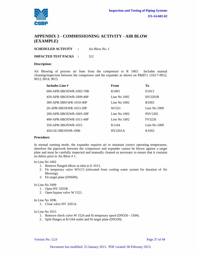
Inspection and Testing of Piping Systems
ES-14-602-02
Version No. 12.0 Page 37 of 44
Document last modified: 25 January 2013. PDF created: 06 February 2013.
APPENDIX 2 - COMMISSIONING ACTIVITY - AIR BLOW (EXAMPLE)
SCHEDULED ACTIVITY : Air Blow No. 1
IMPACTED TEST PACKS : 312
Description:
Air Blowing of process air lines from the compressor to R 1003. Includes manual cleaning/inspection between the compressor and the expander as shown on P&ID’s 1162-7-9012, 9013, 9014, 9015.
Includes Line # From To
600-APR-SBOXWR-1002-70B K1001 E1013
450-APR-SBOXWR-1009-40P Line No 1002 HV3201B
300-APR-SB01WR-1010-40P Line No 1002 R1003
20-APR-SBOXWR-1013-30P W1521 Line No 1009
200-APR-SBOXWR-1003-30P Line No 1002 PSV1205
400-APR-SBOXWR-1011-40P Line No 1002 FV3226
350-APR-SBOXWR-1015 K1164 Line No 1009
450-GE-SBOXWR-1096 HV3201A K1002
Procedure:
In normal running mode, the expander requires air to maintain correct operating temperature, therefore the pipework between the compressor and expander cannot be blown against a target plate and must be carefully inspected and manually cleaned as necessary to ensure that it contains no debris prior to Air Blow # 1.
In Line No 1002 1. Remove flanged elbow at inlet to E 1013. 2. Fit temporary valve W5113 (relocated from cooling water system for duration of Air
Blowing). 3. Fit target plate (DN600).
In Line No 1009
1. Open HV 3201B. 2. Open bypass valve W 1521.
In Line No 1096 1. Close valve HV 3201A.
In Line No 1015
1. Remove check valve W 1524 and fit temporary spool (DN350 - 150#). 2. Split flanges at K1164 outlet and fit target plate (DN350).
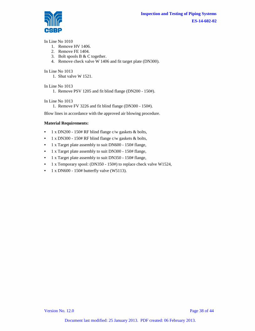
Inspection and Testing of Piping Systems
ES-14-602-02
Version No. 12.0 Page 38 of 44
Document last modified: 25 January 2013. PDF created: 06 February 2013.
In Line No 1010 1. Remove HV 1406. 2. Remove FE 1404. 3. Bolt spools B & C together. 4. Remove check valve W 1406 and fit target plate (DN300).
In Line No 1013
1. Shut valve W 1521. In Line No 1013
1. Remove PSV 1205 and fit blind flange (DN200 - 150#). In Line No 1013
1. Remove FV 3226 and fit blind flange (DN300 - 150#).
Blow lines in accordance with the approved air blowing procedure.
Material Requirements:
• 1 x DN200 - 150# RF blind flange c/w gaskets & bolts,
• 1 x DN300 - 150# RF blind flange c/w gaskets & bolts,
• 1 x Target plate assembly to suit DN600 - 150# flange,
• 1 x Target plate assembly to suit DN300 - 150# flange,
• 1 x Target plate assembly to suit DN350 - 150# flange,
• 1 x Temporary spool: (DN350 - 150#) to replace check valve W1524,
• 1 x DN600 - 150# butterfly valve (W5113).
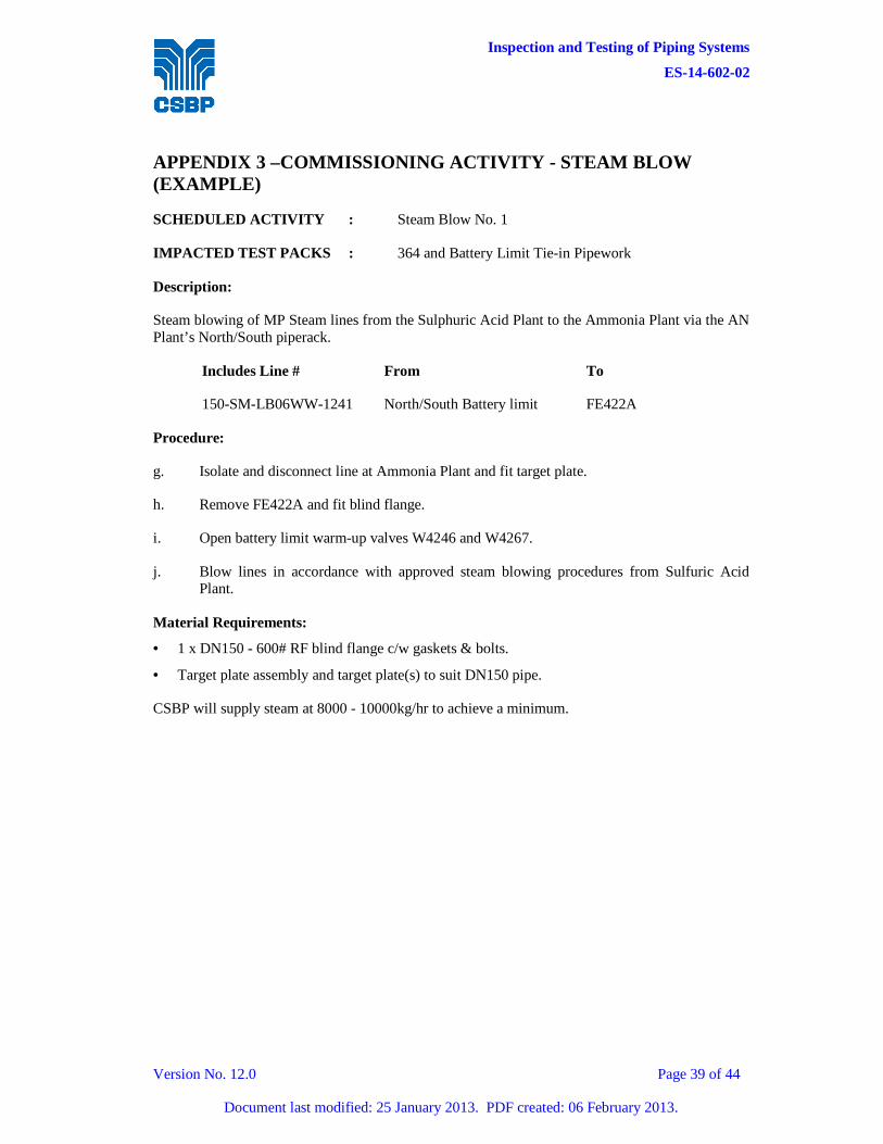
Inspection and Testing of Piping Systems
ES-14-602-02
Version No. 12.0 Page 39 of 44
Document last modified: 25 January 2013. PDF created: 06 February 2013.
APPENDIX 3 –COMMISSIONING ACTIVITY - STEAM BLOW (EXAMPLE)
SCHEDULED ACTIVITY : Steam Blow No. 1
IMPACTED TEST PACKS : 364 and Battery Limit Tie-in Pipework
Description:
Steam blowing of MP Steam lines from the Sulphuric Acid Plant to the Ammonia Plant via the AN Plant’s North/South piperack.
Includes Line # From To
150-SM-LB06WW-1241 North/South Battery limit FE422A
Procedure:
g. Isolate and disconnect line at Ammonia Plant and fit target plate.
h. Remove FE422A and fit blind flange.
i. Open battery limit warm-up valves W4246 and W4267.
j. Blow lines in accordance with approved steam blowing procedures from Sulfuric Acid Plant.
Material Requirements:
• 1 x DN150 - 600# RF blind flange c/w gaskets & bolts.
• Target plate assembly and target plate(s) to suit DN150 pipe.
CSBP will supply steam at 8000 - 10000kg/hr to achieve a minimum.
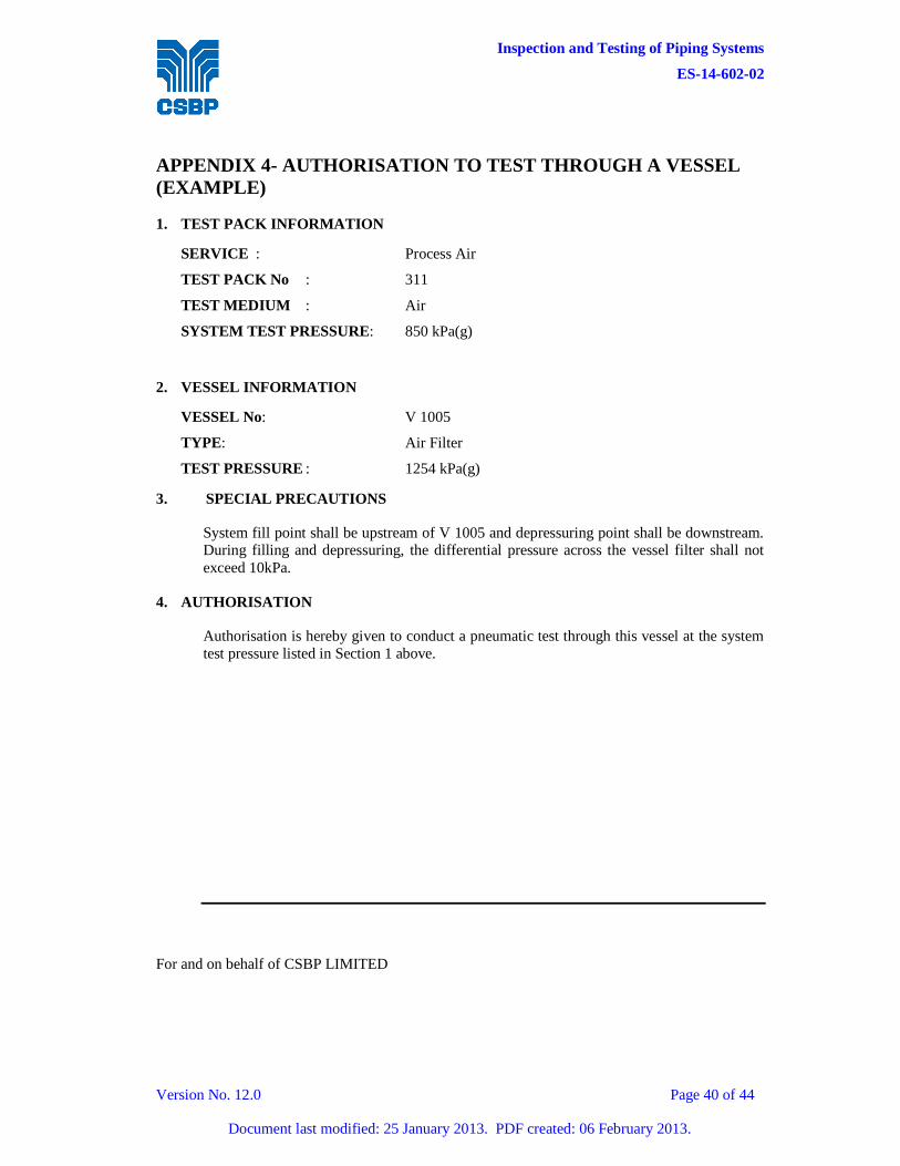
Inspection and Testing of Piping Systems
ES-14-602-02
Version No. 12.0 Page 40 of 44
Document last modified: 25 January 2013. PDF created: 06 February 2013.
APPENDIX 4- AUTHORISATION TO TEST THROUGH A VESSEL (EXAMPLE)
1. TEST PACK INFORMATION
SERVICE : Process Air
TEST PACK No : 311
TEST MEDIUM : Air
SYSTEM TEST PRESSURE: 850 kPa(g)
2. VESSEL INFORMATION
VESSEL No: V 1005
TYPE: Air Filter
TEST PRESSURE : 1254 kPa(g)
3. SPECIAL PRECAUTIONS
System fill point shall be upstream of V 1005 and depressuring point shall be downstream. During filling and depressuring, the differential pressure across the vessel filter shall not exceed 10kPa.
4. AUTHORISATION
Authorisation is hereby given to conduct a pneumatic test through this vessel at the system test pressure listed in Section 1 above.
For and on behalf of CSBP LIMITED

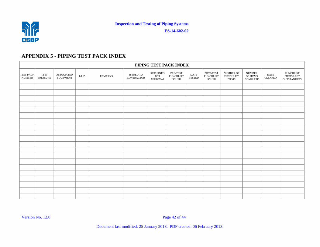
Inspection and Testing of Piping Systems
ES-14-602-02
Version No. 12.0 Page 42 of 44
Document last modified: 25 January 2013. PDF created: 06 February 2013.
APPENDIX 5 - PIPING TEST PACK INDEX
PIPING TEST PACK INDEX
TEST PACK NUMBER
TEST PRESSURE
ASSOCIATED EQUIPMENT
P&ID REMARKS ISSUED TO
CONTRACTOR
RETURNED FOR
APPROVAL
PRE-TEST PUNCHLIST
ISSUED
DATE TESTED
POST-TEST PUNCHLIST
ISSUED
NUMBER OF PUNCHLIST
ITEMS
NUMBER OF ITEMS
COMPLETE
DATE CLEARED
PUNCHLIST ITEMS LEFT
OUTSTANDING

Inspection and Testing of Piping Systems
ES-14-602-02
Version No. 12.0 Page 43 of 44
Document last modified: 25 January 2013. PDF created: 06 February 2013.
APPENDIX 6 - INSPECTION & TEST LOG BOOK
INSPECTION & TEST LOG BOOK
---- This Section to be completed by Contractor ---- ----This Section to be completed by CSBP----
Date Test # Hydro or
Pneumatic Date & Time of Test Name Assigned Inspector
Complete & Accepted Remarks
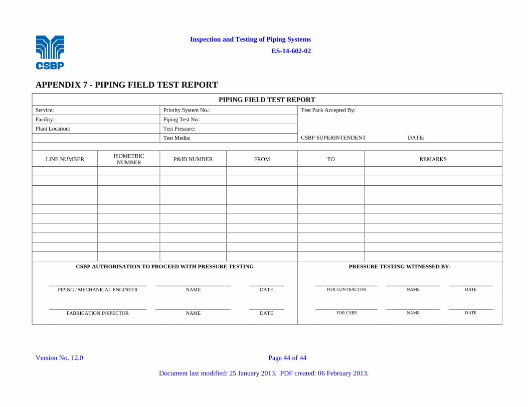
Inspection and Testing of Piping Systems
ES-14-602-02
Version No. 12.0 Page 44 of 44
Document last modified: 25 January 2013. PDF created: 06 February 2013.
APPENDIX 7 - PIPING FIELD TEST REPORT
PIPING FIELD TEST REPORT
Service: Priority System No.: Test Pack Accepted By:
Facility: Piping Test No.:
Plant Location: Test Pressure:
CSBP SUPERINTENDENT
DATE: Test Media:
LINE NUMBER ISOMETRIC NUMBER
P&ID NUMBER FROM TO REMARKS
CSBP AUTHORISATION TO PROCEED WITH PRESSURE TESTING PRESSURE TESTING WITNESSED BY:
PIPING / MECHANICAL ENGINEER NAME DATE FOR CONTRACTOR NAME DATE
FABRICATION INSPECTOR NAME DATE FOR CSBP NAME DATE