Embed Size (px)
Citation preview

Installation and Technical Manual for theLimitless™ Multi-Protocol Receiver, WMPR Series
Sensing and Internet of Things
Issue B
32309669
m WARNINGPERSONAL INJURYDO NOT USE these products as safety or emergency stop devices or in any other application where failure of the product could result in personal injury.
Failure to comply with these instructions could result in death or serious injury.
m WARNINGHoneywell does not recommend using devices for critical control applications where there is, or may be, a single point of failure or where single points of failure may result in an unsafe condition. It is up to the end-user to weigh the risks and benefits to determine if the products are appropriate for the application based on security, safety and performance. Additionally, it is up to the end-user to ensure that the control strategy results in a safe operating condition if any crucial segment of the control solution fails. Honeywell customers assume full responsibility for learning and meeting the required Declaration of Conformity, Regulations, Guidelines, etc. for each country in their distribution market.
Failure to comply with these instructions could result in death or serious injury.
m WARNINGRF EXPOSURETo satisfy FCC RF exposure requirements for mobile transmitting devices, a separation distance of 20 cm or more should be maintained between the antenna of this device and persons during device operation To ensure compliance, operation at closer than this distance is not recommended. The antenna used for this transmission must not be co-located in conjunction with any other antenna or transmitter.
Failure to comply with these instructions could result in death or serious injury.
m WARNINGThe WMPR must be installed in accordance with the requirements specified in this document in order to comply with the specific Country Communication Agency requirements (i.e., FCC, IC, ACMA, etc.). See Section 3 as this requires choosing the correct Country Use Code and thus allowable antenna and/or cable usage.
, CAUTIONPower to the WMPR should not be applied during installation of an antenna as damage could occur to the WMPR electronics.
m WARNING• The cable length of the customer-supplied dc power
source to the WMPR supply terminals cannot exceed three (3) meters.
• The WMPR must be used indoors.• The WMPR must be used inside a cabinet and can only
be accessed during set-up or maintenance.
ii sensing.honeywell.com
Installation and Technical Manual for the Limitless™ Multi-Protocol Receiver, WMPR Series
ISSUE B 32309669
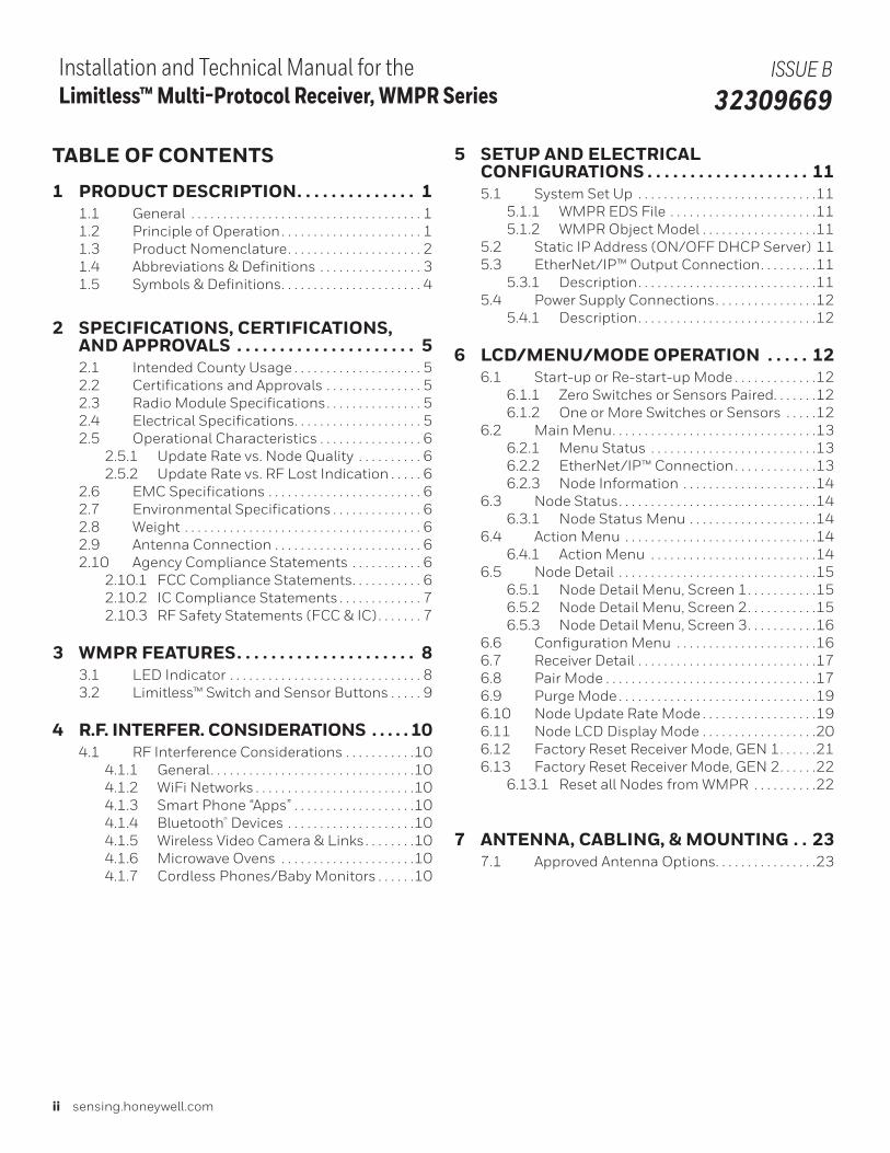
TABLE OF CONTENTS
1 PRODUCT DESCRIPTION. . . . . . . . . . . . . . 1 1.1 General . . . . . . . . . . . . . . . . . . . . . . . . . . . . . . . . . . . . 1 1.2 Principle of Operation . . . . . . . . . . . . . . . . . . . . . . 1 1.3 Product Nomenclature. . . . . . . . . . . . . . . . . . . . . 2 1.4 Abbreviations & Definitions . . . . . . . . . . . . . . . . 3 1.5 Symbols & Definitions. . . . . . . . . . . . . . . . . . . . . . 4
2 SPECIFICATIONS, CERTIFICATIONS, AND APPROVALS . . . . . . . . . . . . . . . . . . . . . 5 2.1 Intended County Usage . . . . . . . . . . . . . . . . . . . . 5 2.2 Certifications and Approvals . . . . . . . . . . . . . . . 5 2.3 Radio Module Specifications. . . . . . . . . . . . . . . 5 2.4 Electrical Specifications. . . . . . . . . . . . . . . . . . . . 5 2.5 Operational Characteristics . . . . . . . . . . . . . . . . 6 2.5.1 Update Rate vs. Node Quality . . . . . . . . . . 6 2.5.2 Update Rate vs. RF Lost Indication . . . . . 6 2.6 EMC Specifications . . . . . . . . . . . . . . . . . . . . . . . . 6 2.7 Environmental Specifications . . . . . . . . . . . . . . 6 2.8 Weight . . . . . . . . . . . . . . . . . . . . . . . . . . . . . . . . . . . . . 6 2.9 Antenna Connection . . . . . . . . . . . . . . . . . . . . . . . 6 2.10 Agency Compliance Statements . . . . . . . . . . . 6 2.10.1 FCC Compliance Statements. . . . . . . . . . . 6 2.10.2 IC Compliance Statements . . . . . . . . . . . . . 7 2.10.3 RF Safety Statements (FCC & IC) . . . . . . . 7
3 WMPR FEATURES. . . . . . . . . . . . . . . . . . . . . 8 3.1 LED Indicator . . . . . . . . . . . . . . . . . . . . . . . . . . . . . . 8 3.2 Limitless™ Switch and Sensor Buttons . . . . . 9
4 R.F. INTERFER. CONSIDERATIONS . . . . . 10 4.1 RF Interference Considerations . . . . . . . . . . .10 4.1.1 General. . . . . . . . . . . . . . . . . . . . . . . . . . . . . . . .10 4.1.2 WiFi Networks . . . . . . . . . . . . . . . . . . . . . . . . .10 4.1.3 Smart Phone “Apps” . . . . . . . . . . . . . . . . . . .10 4.1.4 Bluetooth® Devices . . . . . . . . . . . . . . . . . . . .10 4.1.5 Wireless Video Camera & Links. . . . . . . .10 4.1.6 Microwave Ovens . . . . . . . . . . . . . . . . . . . . .10 4.1.7 Cordless Phones/Baby Monitors . . . . . .10
5 SETUP AND ELECTRICAL CONFIGURATIONS . . . . . . . . . . . . . . . . . . . 11 5.1 System Set Up . . . . . . . . . . . . . . . . . . . . . . . . . . . .11 5.1.1 WMPR EDS File . . . . . . . . . . . . . . . . . . . . . . .11 5.1.2 WMPR Object Model . . . . . . . . . . . . . . . . . .11 5.2 Static IP Address (ON/OFF DHCP Server) 11 5.3 EtherNet/IP™ Output Connection. . . . . . . . .11 5.3.1 Description. . . . . . . . . . . . . . . . . . . . . . . . . . . .11 5.4 Power Supply Connections. . . . . . . . . . . . . . . .12 5.4.1 Description. . . . . . . . . . . . . . . . . . . . . . . . . . . .12
6 LCD/MENU/MODE OPERATION . . . . . 12 6.1 Start-up or Re-start-up Mode . . . . . . . . . . . . .12 6.1.1 Zero Switches or Sensors Paired. . . . . . .12 6.1.2 One or More Switches or Sensors . . . . .12 6.2 Main Menu. . . . . . . . . . . . . . . . . . . . . . . . . . . . . . . .13 6.2.1 Menu Status . . . . . . . . . . . . . . . . . . . . . . . . . .13 6.2.2 EtherNet/IP™ Connection. . . . . . . . . . . . .13 6.2.3 Node Information . . . . . . . . . . . . . . . . . . . . .14 6.3 Node Status. . . . . . . . . . . . . . . . . . . . . . . . . . . . . . .14 6.3.1 Node Status Menu . . . . . . . . . . . . . . . . . . . .14 6.4 Action Menu . . . . . . . . . . . . . . . . . . . . . . . . . . . . . .14 6.4.1 Action Menu . . . . . . . . . . . . . . . . . . . . . . . . . .14 6.5 Node Detail . . . . . . . . . . . . . . . . . . . . . . . . . . . . . . .15 6.5.1 Node Detail Menu, Screen 1. . . . . . . . . . .15 6.5.2 Node Detail Menu, Screen 2. . . . . . . . . . .15 6.5.3 Node Detail Menu, Screen 3. . . . . . . . . . .16 6.6 Configuration Menu . . . . . . . . . . . . . . . . . . . . . .16 6.7 Receiver Detail . . . . . . . . . . . . . . . . . . . . . . . . . . . .17 6.8 Pair Mode . . . . . . . . . . . . . . . . . . . . . . . . . . . . . . . . .17 6.9 Purge Mode . . . . . . . . . . . . . . . . . . . . . . . . . . . . . . .19 6.10 Node Update Rate Mode . . . . . . . . . . . . . . . . . .19 6.11 Node LCD Display Mode . . . . . . . . . . . . . . . . . .20 6.12 Factory Reset Receiver Mode, GEN 1. . . . . .21 6.13 Factory Reset Receiver Mode, GEN 2. . . . . .22 6.13.1 Reset all Nodes from WMPR . . . . . . . . . .22
7 ANTENNA, CABLING, & MOUNTING . . 23 7.1 Approved Antenna Options. . . . . . . . . . . . . . . .23
Sensing and Internet of Things iii
Installation and Technical Manual for the Limitless™ Multi-Protocol Receiver, WMPR Series
ISSUE B 32309669
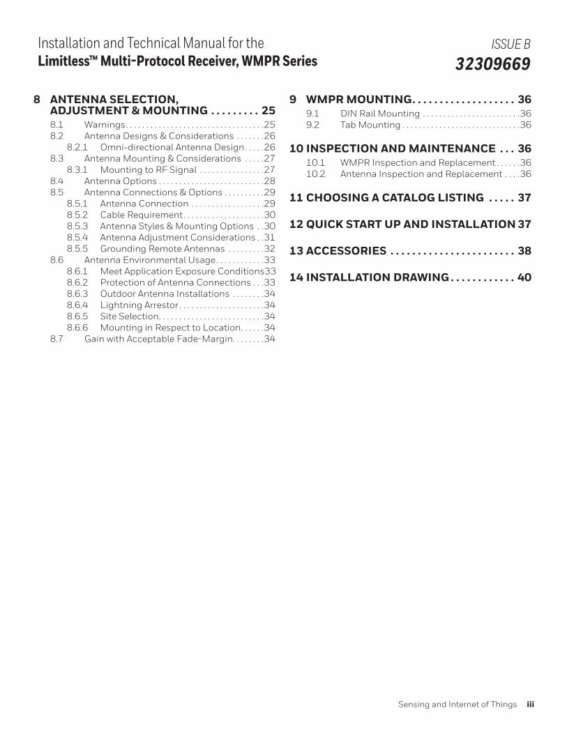
8 ANTENNA SELECTION, ADJUSTMENT & MOUNTING . . . . . . . . . 25 8.1 Warnings. . . . . . . . . . . . . . . . . . . . . . . . . . . . . . . . . .25 8.2 Antenna Designs & Considerations . . . . . . .26 8.2.1 Omni-directional Antenna Design. . . . .26 8.3 Antenna Mounting & Considerations . . . . .27 8.3.1 Mounting to RF Signal . . . . . . . . . . . . . . . .27 8.4 Antenna Options . . . . . . . . . . . . . . . . . . . . . . . . . .28 8.5 Antenna Connections & Options . . . . . . . . . .29 8.5.1 Antenna Connection . . . . . . . . . . . . . . . . . .29 8.5.2 Cable Requirement. . . . . . . . . . . . . . . . . . . .30 8.5.3 Antenna Styles & Mounting Options . .30 8.5.4 Antenna Adjustment Considerations . .31 8.5.5 Grounding Remote Antennas . . . . . . . . .32 8.6 Antenna Environmental Usage. . . . . . . . . . . .33 8.6.1 Meet Application Exposure Conditions 33 8.6.2 Protection of Antenna Connections . . .33 8.6.3 Outdoor Antenna Installations . . . . . . . .34 8.6.4 Lightning Arrestor . . . . . . . . . . . . . . . . . . . . .34 8.6.5 Site Selection. . . . . . . . . . . . . . . . . . . . . . . . . .34 8.6.6 Mounting in Respect to Location. . . . . .34 8.7 Gain with Acceptable Fade-Margin. . . . . . . .34
9 WMPR MOUNTING. . . . . . . . . . . . . . . . . . . 36 9.1 DIN Rail Mounting . . . . . . . . . . . . . . . . . . . . . . . .36 9.2 Tab Mounting . . . . . . . . . . . . . . . . . . . . . . . . . . . . .36
10 INSPECTION AND MAINTENANCE . . . 36 10.1 WMPR Inspection and Replacement . . . . . .36 10.2 Antenna Inspection and Replacement . . . .36
11 CHOOSING A CATALOG LISTING . . . . . 37
12 QUICK START UP AND INSTALLATION 37
13 ACCESSORIES . . . . . . . . . . . . . . . . . . . . . . . 38
14 INSTALLATION DRAWING . . . . . . . . . . . . 40
iv sensing.honeywell.com
Installation and Technical Manual for the Limitless™ Multi-Protocol Receiver, WMPR Series
ISSUE B 32309669
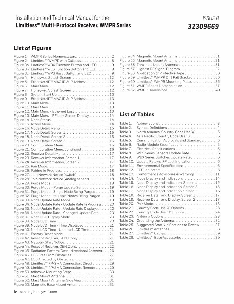
List of FiguresFigure 1. WMPR Series Nomenclature . . . . . . . . . . . . . . . . . . . . . . . 2Figure 2. Limitless™ WMPR with Callouts . . . . . . . . . . . . . . . . . . . . 8Figure 3a. Limtless™ WBX Function Button and LED . . . . . . . . . 9Figure 3b. Limtless™ WLS Function Button and LED . . . . . . . . . 9Figure 3c. Limtless™ WPS Reset Button and LED . . . . . . . . . . . . . 9Figure 4. Honeywell Splash Screen . . . . . . . . . . . . . . . . . . . . . . . . . 12Figure 5. EtherNet/IP™ MAC ID & IP Address . . . . . . . . . . . . . . . 12Figure 6. Main Menu . . . . . . . . . . . . . . . . . . . . . . . . . . . . . . . . . . . . . . . 12Figure 7. Honeywell Splash Screen . . . . . . . . . . . . . . . . . . . . . . . . . 12Figure 8. System Start Up . . . . . . . . . . . . . . . . . . . . . . . . . . . . . . . . . . 13Figure 9. EtherNet/IP™ MAC ID & IP Address . . . . . . . . . . . . . . . 13Figure 10. Main Menu . . . . . . . . . . . . . . . . . . . . . . . . . . . . . . . . . . . . . . . 13Figure 11. Main Menu . . . . . . . . . . . . . . . . . . . . . . . . . . . . . . . . . . . . . . . 13Figure 12. Main Menu - Ethernet Lost . . . . . . . . . . . . . . . . . . . . . . . 13Figure 13. Main Menu - RF Lost Screen Display . . . . . . . . . . . . . 14Figure 14. Node Status . . . . . . . . . . . . . . . . . . . . . . . . . . . . . . . . . . . . . . 14Figure 15. Action Menu . . . . . . . . . . . . . . . . . . . . . . . . . . . . . . . . . . . . . . 14Figure 16. Node Detail Menu . . . . . . . . . . . . . . . . . . . . . . . . . . . . . . . . 15Figure 17. Node Detail, Screen 1 . . . . . . . . . . . . . . . . . . . . . . . . . . . . . 15Figure 18. Node Detail, Screen 2 . . . . . . . . . . . . . . . . . . . . . . . . . . . . . 15Figure 19. Node Detail, Screen 3 . . . . . . . . . . . . . . . . . . . . . . . . . . . . . 16Figure 20. Configuration Menu . . . . . . . . . . . . . . . . . . . . . . . . . . . . . . 16Figure 21. Configuration Menu, continued . . . . . . . . . . . . . . . . . . 16Figure 22. Receiver Detail Menu . . . . . . . . . . . . . . . . . . . . . . . . . . . . . 17Figure 23. Receiver Information, Screen 1 . . . . . . . . . . . . . . . . . . . 17Figure 24. Receiver Information, Screen 2 . . . . . . . . . . . . . . . . . . . 17Figure 25. Pair Mode . . . . . . . . . . . . . . . . . . . . . . . . . . . . . . . . . . . . . . . . . 17Figure 26. Pairing in Progress . . . . . . . . . . . . . . . . . . . . . . . . . . . . . . . . 18Figure 27. Join Network Notice (switch) . . . . . . . . . . . . . . . . . . . . . 18Figure 28. Join Network Notice (Analog sensor) . . . . . . . . . . . . . 18Figure 29. Purge Mode . . . . . . . . . . . . . . . . . . . . . . . . . . . . . . . . . . . . . . 19Figure 30. Purge Mode - Purge Update Sent . . . . . . . . . . . . . . . . . 19Figure 31. Purge Mode - Single Node Being Purged . . . . . . . . . 19Figure 32. Purge Mode - Multiple Nodes Being Purged . . . . . . 19Figure 33. Node Update Rate Mode. . . . . . . . . . . . . . . . . . . . . . . . . . 19Figure 34. Node Update Rate - Update Rate in Progress . . . . . 20Figure 35. Node Update Rate - Update Rate Displayed . . . . . . 20Figure 36. Node Update Rate - Changed Update Rate . . . . . . . 20Figure 37. Node LCD Display Mode . . . . . . . . . . . . . . . . . . . . . . . . . . 20Figure 38. Node LCD Time . . . . . . . . . . . . . . . . . . . . . . . . . . . . . . . . . . . 20Figure 39. Node LCD Time - Time Displayed . . . . . . . . . . . . . . . . . 21Figure 40. Node LCD Time - Updated LCD Time . . . . . . . . . . . . . 21Figure 41. Factory Reset Mode . . . . . . . . . . . . . . . . . . . . . . . . . . . . . . 21Figure 42. Reset of Receiver, GEN 1 only . . . . . . . . . . . . . . . . . . . . . 21Figure 43. Network Start Notice. . . . . . . . . . . . . . . . . . . . . . . . . . . . . . 21Figure 44. Reset of Receiver, GEN 2 only . . . . . . . . . . . . . . . . . . . . . 22Figure 45. Radiation Pattern/Omni-directional Antenna . . . . . 26Figure 46. LOS Free From Obstacles . . . . . . . . . . . . . . . . . . . . . . . . . 27Figure 47. LOS Affected by Obstacles . . . . . . . . . . . . . . . . . . . . . . . . 27Figure 48. Limitless™ RP-SMA Connection, Direct . . . . . . . . . . . 29Figure 49. Limitless ™ RP-SMA Connection, Remote . . . . . . . . . 29Figure 50. Adhesive Mounting Steps . . . . . . . . . . . . . . . . . . . . . . . . . 30Figure 51. Mast Mount Antenna . . . . . . . . . . . . . . . . . . . . . . . . . . . . . 31Figure 52. Mast Mount Antenna, Side View . . . . . . . . . . . . . . . . . . 31Figure 53. Magnetic Base Mount Antenna . . . . . . . . . . . . . . . . . . . 31
Figure 54. Magnetic Mount Antenna . . . . . . . . . . . . . . . . . . . . . . . . 31Figure 55. Magnetic Mount Antenna . . . . . . . . . . . . . . . . . . . . . . . . 31Figure 56. Thru-hole Mount Antenna . . . . . . . . . . . . . . . . . . . . . . . . 31Figure 57. Highest RF Signal Diagram . . . . . . . . . . . . . . . . . . . . . . . 32Figure 58. Application of Protective Tape . . . . . . . . . . . . . . . . . . . . 33Figure 59. Limitless™ WMPR DIN Rail Bracket . . . . . . . . . . . . . . . 36Figure 60. Limitless™ WMPR Mounting Plate . . . . . . . . . . . . . . . . 36Figure 61. WMPR Series Nomenclature . . . . . . . . . . . . . . . . . . . . . . 37Figure 62. WMPR Dimensions . . . . . . . . . . . . . . . . . . . . . . . . . . . . . . . 40
List of TablesTable 1. Abbreviations . . . . . . . . . . . . . . . . . . . . . . . . . . . . . . . . . . . . . . 3Table 2. Symbol Definitions . . . . . . . . . . . . . . . . . . . . . . . . . . . . . . . . 4 Table 3. North America: Country Code Use “A” . . . . . . . . . . . . . . 5Table 4. Asia Pacific: Country Code Use “B” . . . . . . . . . . . . . . . . . 5Table 5. Communication Approvals and Standards . . . . . . . . . 5Table 6. Radio Module Specifications . . . . . . . . . . . . . . . . . . . . . . 5Table 7. Electrical Specifications . . . . . . . . . . . . . . . . . . . . . . . . . . . 5Table 8. WPS Series Sensors Update Rate . . . . . . . . . . . . . . . . . . 6Table 9. WBX Series Switches Update Rate . . . . . . . . . . . . . . . . . 6Table 10. Update Rate vs. RF Lost Indication . . . . . . . . . . . . . . . . 6Table 11. Environmental Specifications . . . . . . . . . . . . . . . . . . . . . 6Table 12. LED Indicators . . . . . . . . . . . . . . . . . . . . . . . . . . . . . . . . . . . . . 8Table 13. Conformance Advisories & Warnings . . . . . . . . . . . . . 11Table 14. Node Display and Indication . . . . . . . . . . . . . . . . . . . . . . 14Table 15. Node Display and Indication, Screen 1 . . . . . . . . . . . 15Table 16. Node Display and Indication, Screen 2 . . . . . . . . . . . 15Table 17. Node Display and Indication, Screen 3 . . . . . . . . . . . 16Table 18. Receiver Detail and Display, Screen 1 . . . . . . . . . . . . . 17Table 19. Receiver Detail and Display, Screen 2 . . . . . . . . . . . . . 17Table 20. Pair Mode . . . . . . . . . . . . . . . . . . . . . . . . . . . . . . . . . . . . . . . . . 18Table 21. Country Code Use “A” Options . . . . . . . . . . . . . . . . . . . . 23Table 22. Country Code Use “B” Options . . . . . . . . . . . . . . . . . . . . 24Table 23. Antenna Options . . . . . . . . . . . . . . . . . . . . . . . . . . . . . . . . . . 28Table 24. Grounding the Antenna . . . . . . . . . . . . . . . . . . . . . . . . . . . 32Table 25. Suggested Start-Up Sections to Review . . . . . . . . . . 37Table 26. Limitless™ Antennas . . . . . . . . . . . . . . . . . . . . . . . . . . . . . . 38Table 27. Limitless™ Cables . . . . . . . . . . . . . . . . . . . . . . . . . . . . . . . . . 39Table 28. Limitless™ Base Accessories . . . . . . . . . . . . . . . . . . . . . . 39
Sensing and Internet of Things 1
Installation and Technical Manual for the Limitless™ Multi-Protocol Receiver, WMPR Series
ISSUE B 32309669
1 | PRODUCT DESCRIPTION
1.1 | GeneralThe Limitless™ Series uses the latest commercial off-the-shelf wireless technology that can be used in a wide variety of applications. This is especially beneficial for remote monitoring applications where previous wiring installation or wire maintenance was not physically possible or economically feasible. This document will provide installation instructions to properly install a Limitless™ Wireless Multi-Protocol Receiver WMPR, as well as a detailed understanding of its functions.
1.2 | Principle of OperationA Limitless™ input sends an RF signal to the WMPR when the Limitless™ digital or analog input changes state. There may be up to 14 Limitless™ digital or analog inputs that communicate and indicate their state to a single WMPR. The WMPR receiver is menu driven through the use of function buttons and a easy to read LCD display. The menu allows you to see status of the nodes, configure nodes, and update receiver functionality. A change of state of a Limitless ™ input will cause a corresponding change in output of the particular node to be output via an EtherNet/IP™ output. The WMPR indicates low battery conditions, lost RF links, as well as other diagnostic and functional operations described in further detail throughout this manual.
Intended AudienceThis guide is intended for people who are responsible for plan-ning, configuring, administering, and operating the Limitless™ Network.
Prerequisite SkillsIt is assumed that you are familiar with the operation of Limit-less™ Networks.
About this DocumentThis document outlines professional installation requirements for the Limitless™ Receiver, WMPR Series. Professional instal-lation is required to comply with certification agency and legal requirements. This document must be adhered to for all instal-lations of the Limitless™ Receiver, WMPR Series.
These devices are not intended for critical control where there is a single point of failure or where single points of failure result in unsafe conditions. As with any process control solution, it is the end users’ responsibility to weigh the risks and benefits to determine if the products used are the right match for the application based on security, safety, regulations, and perfor-mance.
ReferencesThe following list identifies all documents that may be sources of reference for material discussed in this publication.
Document title Document No. Product Usage
WMPR0003000700100100.eds Contact Honeywell GEN code Version 1 only
WMPR0003000700100100_V210.eds Contact Honeywell GEN code Version 2 only
Limitless™ WMPR Series Wireless Multi-Protocol Receiver EtherNet/IP™ Object Model
32308916 ALL
2 sensing.honeywell.com
Installation and Technical Manual for the Limitless™ Multi-Protocol Receiver, WMPR Series
ISSUE B 32309669
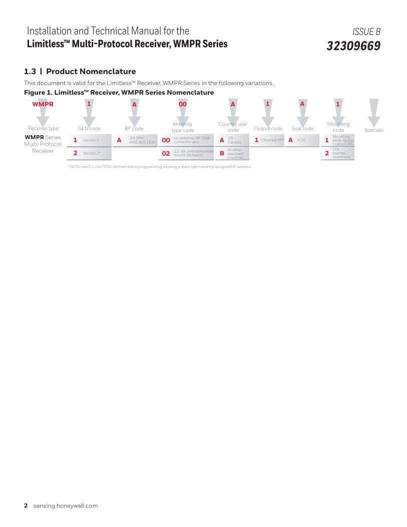
1.3 | Product NomenclatureThis document is valid for the Limitless™ Receiver, WMPR Series in the following variations.
Figure 1. Limitless™ Receiver, WMPR Series Nomenclature
WMPR
Receiver type
A
Country use code
A
B
US, Canada
All otherapproved countries
WMPR SeriesMulti-Protocol
Receiver
1
GEN code
A
RF code
1 Version 1 A 2.4 GHz; IEEE 802.15.4
00
02
00 No antenna; RP-SMA connector jack
2.2 dBi omni w/receiver mount; tilt/swivel
Antenna type code
1
Output code
1 EtherNet/IP™
A
Seal code
A IP20
1
Mountingcode
1
2
Mountingplate, epoxycoated CRSDINbracket, aluminum
Specials
2 Version 2*
*GEN code 2 is not ODVA certfied due to programming allowing a static (permanently assigned) IP address.

Sensing and Internet of Things 3
Installation and Technical Manual for the Limitless™ Multi-Protocol Receiver, WMPR Series
ISSUE B 32309669
1.4 | Abbreviations and DefinitionsTable 1. AbbreviationsACMA Australian Communications and Media Authority
CRS Cold-rolled steel
dB Decibel
dBi Decibel Isotropic
dBm Decibel above or below 1 milliwatt
DSSS Direct Sequence Spread Spectrum
EIRP Equivalent isotropic radiated power
EMC Electromagnetic Compatibility
ETSI European Telecommunications Standards Institute
EU European Union
FCC Federal Communications Committee
ft-lb Foot-pounds
GHz GigaHertz
IC Industry Canada
ICES Industry Canada Electrical Specification
IEEE Institute of Electrical and Electronics Engineers
IP Internet Protocol
ISO International Organization of Standardization
kbps KiloBits Per Second
LED Light Emitting Diode
MAC ID Media Access Control address
MHz MegaHertz
MPE Maximum Permissible Exposure
NA North America – United States of America and Canada
NEMA National Electrical Manufacturers Association
ODVA Open DeviceNet Vendors Association
R&TTE Radio and Telecommunications Terminal Equipment
RP-SMA Reverse Polarity SMA connector
RF Radio Frequency
RSS Radio Standards Specifications
TX Transmit Power
WBX Wireless Hazardous Area Limit Switch
WDRR Wireless DIN Rail Receiver
WGLA Wireless Global Limit Switch Series
WLS Wireless Limit Switch
WMPR Wireless Multi-Protocol Receiver
WOI Wireless Operator Interface
WPS Wireless Pressure Sensor
4 sensing.honeywell.com
Installation and Technical Manual for the Limitless™ Multi-Protocol Receiver, WMPR Series
ISSUE B 32309669
1.5 | Symbol Definitions
The following table lists those symbols used in this document to denote certain conditions.
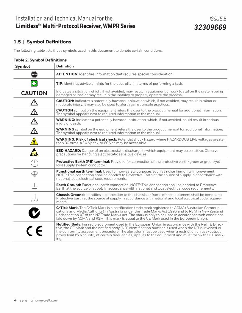
Table 2. Symbol DefinitionsSymbol Definition
, ATTENTION: Identifies information that requires special consideration.
TIP: Identifies advice or hints for the user, often in terms of performing a task.
CAUTION Indicates a situation which, if not avoided, may result in equipment or work (data) on the system being damaged or lost, or may result in the inability to properly operate the process.
m CAUTION: Indicates a potentially hazardous situation which, if not avoided, may result in minor or moderate injury. It may also be used to alert against unsafe practices.
m CAUTION symbol on the equipment refers the user to the product manual for additional information. The symbol appears next to required information in the manual.
m WARNING: Indicates a potentially hazardous situation, which, if not avoided, could result in serious injury or death.
m WARNING symbol on the equipment refers the user to the product manual for additional information. The symbol appears next to required information in the manual.
WARNING, Risk of electrical shock: Potential shock hazard where HAZARDOUS LIVE voltages greater than 30 Vrms, 42.4 Vpeak, or 60 Vdc may be accessible.
ESD HAZARD: Danger of an electrostatic discharge to which equipment may be sensitive. Observe precautions for handling electrostatic sensitive devices.
Protective Earth (PE) terminal: Provided for connection of the protective earth (green or green/yel-low) supply system conductor.
Functional earth terminal: Used for non-safety purposes such as noise immunity improvement. NOTE: This connection shall be bonded to Protective Earth at the source of supply in accordance with national local electrical code requirements.
Earth Ground: Functional earth connection. NOTE: This connection shall be bonded to Protective Earth at the source of supply in accordance with national and local electrical code requirements.
Chassis Ground: Identifies a connection to the chassis or frame of the equipment shall be bonded to Protective Earth at the source of supply in accordance with national and local electrical code require-ments.
C-Tick Mark. The C-Tick Mark is a certification trade mark registered to ACMA (Australian Communi-cations and Media Authority) in Australia under the Trade Marks Act 1995 and to RSM in New Zealand under section 47 of the NZ Trade Marks Act. The mark is only to be used in accordance with conditions laid down by ACMA and RSM. This mark is equal to the CE Mark used in the European Union.
Notified Body. For radio equipment used in the European Union in accordance with the R&TTE Direc-tive, the CE Mark and the notified body (NB) identification number is used when the NB is involved in the conformity assessment procedure. The alert sign must be used when a restriction on use (output power limit by a country at certain frequencies) applies to the equipment and must follow the CE mark-ing.
Sensing and Internet of Things 5
Installation and Technical Manual for the Limitless™ Multi-Protocol Receiver, WMPR Series
ISSUE B 32309669
2 | SPECIFICATIONS, CERTIFICATIONS, AND APPROVALS
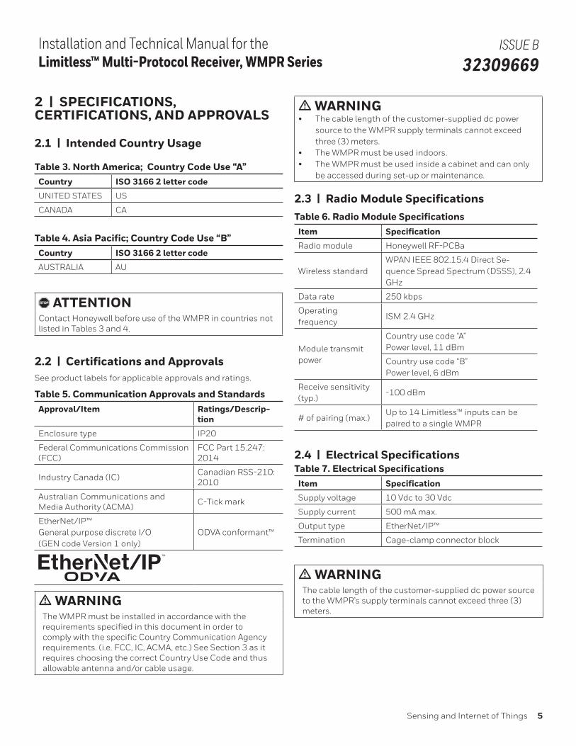
2.1 | Intended Country Usage
Table 3. North America; Country Code Use “A”Country ISO 3166 2 letter code
UNITED STATES US
CANADA CA
Table 4. Asia Pacific; Country Code Use “B”Country ISO 3166 2 letter code
AUSTRALIA AU
, ATTENTIONContact Honeywell before use of the WMPR in countries not listed in Tables 3 and 4.
2.2 | Certifications and ApprovalsSee product labels for applicable approvals and ratings.
Table 5. Communication Approvals and StandardsApproval/Item Ratings/Descrip-
tion
Enclosure type IP20
Federal Communications Commission (FCC)
FCC Part 15.247: 2014
Industry Canada (IC)Canadian RSS-210: 2010
Australian Communications and Media Authority (ACMA)
C-Tick mark
EtherNet/IP™ General purpose discrete I/O (GEN code Version 1 only)
ODVA conformant™
m WARNINGThe WMPR must be installed in accordance with the requirements specified in this document in order to comply with the specific Country Communication Agency requirements. (i.e. FCC, IC, ACMA, etc.) See Section 3 as it requires choosing the correct Country Use Code and thus allowable antenna and/or cable usage.
m WARNING• The cable length of the customer-supplied dc power
source to the WMPR supply terminals cannot exceed three (3) meters.
• The WMPR must be used indoors.• The WMPR must be used inside a cabinet and can only
be accessed during set-up or maintenance.
2.3 | Radio Module Specifications Table 6. Radio Module SpecificationsItem Specification
Radio module Honeywell RF-PCBa
Wireless standard WPAN IEEE 802.15.4 Direct Se-quence Spread Spectrum (DSSS), 2.4 GHz
Data rate 250 kbps
Operating frequency
ISM 2.4 GHz
Module transmit power
Country use code “A” Power level, 11 dBm
Country use code “B” Power level, 6 dBm
Receive sensitivity (typ.)
-100 dBm
# of pairing (max.)Up to 14 Limitless™ inputs can be paired to a single WMPR
2.4 | Electrical Specifications Table 7. Electrical SpecificationsItem Specification
Supply voltage 10 Vdc to 30 Vdc
Supply current 500 mA max.
Output type EtherNet/IP™
Termination Cage-clamp connector block
m WARNINGThe cable length of the customer-supplied dc power source to the WMPR’s supply terminals cannot exceed three (3) meters.
6 sensing.honeywell.com
Installation and Technical Manual for the Limitless™ Multi-Protocol Receiver, WMPR Series
ISSUE B 32309669
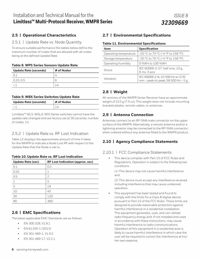
2.7 | Environmental Specifications
Table 11. Environmental SpecificationsItem Specification
Operating temperature -20 °C to 70 °C [-4 °F to 158 °F]
Storage temperature -20 °C to 70 °C [-4 °F to 158 °F]
Operating humidity 0 %RH to 100 %RH
ShockIEC 60068-2-27; half sine, 10 g, 6 ms, 3 axis
VibrationIEC 60068-2-6; 10-500 Hz w/ 0.35 mm – peak-to-peak, 58-500 Hz – 5 g
2.8 | WeightAll versions of the WMPR Series Receiver have an approximate weight of 215 g [7.5 oz]. This weight does not include mounting brackets/plates, remote cables, or antennas.
2.9 | Antenna ConnectionAntennas connect to an RP-SMA male connector on the upper surface of the WMPR. Alternatively, a remote antenna and/or a lightning arrestor may be connected to the RP-SMA connector; when ordered without any antenna fitted to the WMPR product.
2.10 | Agency Compliance Statements
2.10.1 | FCC Compliance Statements
• This device complies with Part 15 of FCC Rules and Regulations. Operation is subject to the following two conditions:
(1) This device may not cause harmful interference and
(2) This device must accept any interference received, including interference that may cause undesired operation.
• This equipment has been tested and found to comply with the limits for a Class B digital device, pursuant to Part 15 of the FCC Rules. These limits are designed to provide reasonable protection against harmful interference in a residential installation. This equipment generates, uses, and can radiate radio frequency energy and, if not installed and used in accordance with these instructions, may cause harmful interference to radio communications. Operation of this equipment in a residential area is likely to cause harmful interference in which case the user will be required to correct the interference at his/her own expense.
2.5 | Operational Characteristics
2.5.1 | Update Rate vs. Node Quantity To ensure suitable performance the tables below define the maximum number of nodes that are allowed with all nodes being at the defined Update Rate:
Table 8. WPS Series Sensors Update RateUpdate Rate (seconds) # of Nodes
0.1 4
0.25, 0.5 6
> 1 14
Table 9. WBX Series Switches Update RateUpdate Rate (seconds) # of Nodes
> 1 14
Limitless™ WLS, WGLA, WOI Series switches cannot have the update rate changed and are factory set at 30 seconds; number of nodes: 14.
2.5.2 | Update Rate vs. RF Lost Indication Table 12 displays the approximate amount of time it takes for the WMPR to indicate a Node Lost RF with respect to the Update Rate that the Node is set to.
Table 10. Update Rate vs. RF Lost Indication Update Rate (sec) RF Lost Indication (approx. sec)
0.1 0.5
0.25 1
0.5 2
1 5
5 18
10 45
30 120
90 360
2.6 | EMC SpecificationsThe latest applicable EMC Standards are as follows:
• EN 300 328, V1.8.1
• EN 61326-1 (2013)
• EN 301 489-1, V1.9.2
• EN 301 489-17, V2.2.1

Sensing and Internet of Things 7
Installation and Technical Manual for the Limitless™ Multi-Protocol Receiver, WMPR Series
ISSUE B 32309669
• Intentional or unintentional changes or modifications must not be made to the WMPR unless under the express consent of the party responsible for compliance. Any such modifications could void the user’s authority to operate the equipment and will void the manufacturer’s warranty.
2.10.2 | Industry Canada (IC) Compliance Statements
• To reduce potential radio interference to other users, the antenna type and its gain should be chosen so that the equivalent isotropic radiated power (EIRP) is not more than that permitted for successful communication.
• Operation is subject to the following two conditions:
(1) this device may not cause interference, and
(2) this device must accept any interference, including interference that may cause undesired operation of the device.
• This Class A digital apparatus has been tested and found to comply with Canadian RSS-210:2010.
• This radio transmitter (identify device by certification number) has been approved by Industry Canada to operate with the antenna types listed below with the maximum permissiable gain indicated. Antenna types not included in this list, have a gain greater than the maximum gain indicated for that type, are strictly prohibited for use with this device
- Antenna type approved for use: Omni - Antenna gain (max.): 9 dBi
• Pour réduire les interférences radio potentielles aux autres utilisateurs, le type d’antenne et son gain doivent être choisis de telle sorte que l’équivalent isotrope puissance rayonnée (PIRE) ne est pas supérieure à celle permise pour une communication réussie.
• Son fonctionnement est soumis aux deux conditions suivantes:
(1) ce dispositif ne doit pas causer d’interférences et
(2) cet appareil doit accepter toute interférence, y compris les interférences qui peuvent causer un mauvais fonctionnement de l’appareil.
• Cet appareil numérique de classe A est conforme avec Industrie Canada RSS 210: 2010.
• Cet émetteur radio (appareil identifié par numéro de certification) a été approuvé par Industry Canada pour fonctionner avec les types d’antenne répertoriés ci-dessous et présentant le gain maximal admissible indiqué. Utiliser des types d’antennes non mentionnés dans cette liste ou présentant un gain supérieur au maximum indiqué pour ce type est strictement interdit.
- Type d’antenne approuvé : Toutes directions
- Gain d’antenne (max.) : 9 dBi
2.10.3 | Radio Frequency (RF) Safety Statements (FCC & IC)To comply with FCC’s and Industry Canada’s RF exposure requirements, the following antenna installation and device operating configurations must be satisfied.
• Remote antenna for this unit must be fixed and mounted on outdoor permanent structures with a separation distance between any other antenna(s) of greater than 20 cm [7.87 in] and a separation distance of at least 20 cm [7.87 in] from all persons.
• Furthermore, when using an direct-mount antenna with the WBX, it must not be co-located with any other antenna or transmitter device and it must have a separation distance of at least 20 cm [7.87 in] from all persons.
8 sensing.honeywell.com
Installation and Technical Manual for the Limitless™ Multi-Protocol Receiver, WMPR Series
ISSUE B 32309669
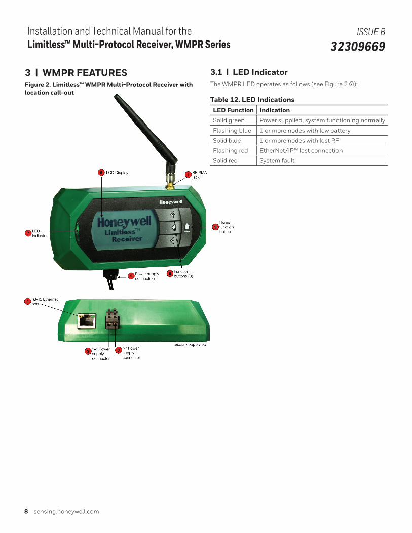
3 | WMPR FEATURES Figure 2. Limitless™ WMPR Multi-Protocol Receiver with location call-out
3.1 | LED IndicatorThe WMPR LED operates as follows (see Figure 2 7):
Table 12. LED IndicationsLED Function Indication
Solid green Power supplied, system functioning normally
Flashing blue 1 or more nodes with low battery
Solid blue 1 or more nodes with lost RF
Flashing red EtherNet/IP™ lost connection
Solid red System fault
Sensing and Internet of Things 9
Installation and Technical Manual for the Limitless™ Multi-Protocol Receiver, WMPR Series
ISSUE B 32309669
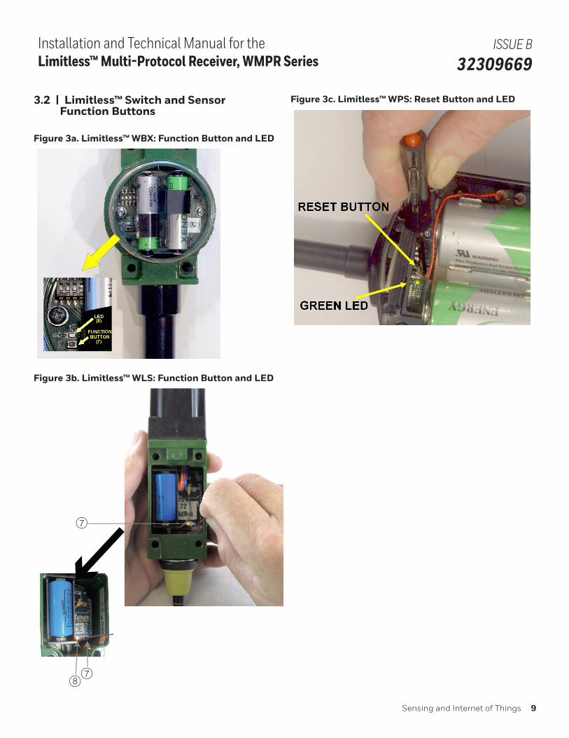
3.2 | Limitless™ Switch and Sensor Function Buttons
Figure 3a. Limitless™ WBX: Function Button and LED
Figure 3b. Limitless™ WLS: Function Button and LED
7
78
Figure 3c. Limitless™ WPS: Reset Button and LED
10 sensing.honeywell.com
Installation and Technical Manual for the Limitless™ Multi-Protocol Receiver, WMPR Series
ISSUE B 32309669
4 | R.F. INTERFERENCE CONSIDERATIONS
4.1 | R.F. Interference Considerations
4.1.1 | GeneralThe 802.15.4 specification provides a high resistance to inter-ference. Within the 2.4 GHz band, there are 16 channels, each using approximately 2 MHz of bandwidth. The channel used may be rapidly changed depending on the presence of other signals sensed in that channel. Thus narrow band interfering signals may have no effect, while broadband noise sources may cause loss. The effect of light to moderate interference is not to make the system fail, but to increase the rate of “lost packets” of data. These “lost packets” are simply retransmitted as needed, so the user may not notice any problem. More serious interfer-ence can cause loss of more data updates, and error messages reported by the WMPR, as well as shorter battery life.
4.1.2 | WiFi NetworksMost WiFi (WLAN) networks operate in the same 2.4 GHz range and use wider bands within that range. Also, the faster proto-cols (802.11N or AC), may utilize multiple channels. Factors af-fecting R.F. interference would be channel separation, distance separation, and duty cycle.
• Channel separation: Studies have shown that a channel separation of 7 MHz will make interference less likely. WiFi routers can be set to use different channels as needed, and auto channel modes can be disabled. If possible, switch-ing to a 5 GHz-only protocol (using 802.11N or AC), would eliminate any possibility of 2.4 GHz interference.
• Distance separation: A physical separation of 10 meters or more will reduce possibility of interference.
• Duty Cycle: Generally the duty cycle of WiFi routers is very low for simple uses as e-mailing, messaging, most web browsing, and voice protocols. However, a video camera or multiple users streaming video would cause a significant increase in bandwidth usage and increase the possibility of interference, making channel or distance separation more desirable.
Regarding the WiFi client (laptop, smartphone, tablet), they are much less of a problem as they generally operate with a much reduced duty cycle (most data is received by the device), and may operate with much lower transmit power
4.1.3 | Smart Phone “Apps”Smart phone “apps” are available to display consumer WiFi signal strengths or download/upload speeds. These apps will not display the 802.15.4 signals as the packet format is
different. However, if a suspected interference source causes a large reduction in consumer WiFi download speed, it is likely it could also cause interference to the 802.15.4 data used by the WMPR.
4.1.4 | Bluetooth® DevicesBluetooth® interference is less of an issue, due to the very narrow bandwidth of Bluetooth® signals, the low transmit power, and the rapid “frequency hopping” of the signals. If the 802.15.4 device misses a packet of data due to a Bluetooth® burst of data, the re-transmission of the 802.15.4 data will likely succeed, as the Bluetooth® will have hopped to a different channel by then.
4.1.5 | Wireless Video Camera and Video LinksWireless video links operating in the 2.4 GHz band can cause serious interference as they are operating continuously, use a wide (6 MHz) bandwidth), and may be more powerful. Interfer-ence from wireless video could cause the “NO RF” indication in severe cases. As mentioned, frequency and/or distance separa-tion may be required.
• Frequency Separation: Many video links have four or more channels selectable. Changing channels may help. Addi-tionally, wireless video links are available in the 900 MHz band, and the 1.2 GHz band. Switching to one of those would eliminate interference issues with 802.15.4 (and 802.11x).
• Distance Separation: Separating the video link sensor from the WMPR would be very desirable. Alternatively, utilizing directional antennas on the WMPR, and /or on the wireless video link would help greatly.
4.1.6 | Microwave OvensMicrowave ovens operate in the 2.4 GHz range, they are power-ful, and a high-duty cycle. However, they may not be a problem to a modern 802.15.4 network. The magnetron in a microwave oven is driven by half-wave rectified AC, so the R.F. output is actually off for one half of the 60 Hz or 50 Hz power line cycle (8.33 msec or 10.0 msec). During that part of the cycle, the packets of 802.15.4 data may succeed. However, close to half of the packets may require retransmission, so data throughput could be greatly reduced.
4.1.7 | Cordless Phones/Baby Monitors/ IntercomsA 2.4 GHz cordless phone in very close proximity to a wireless sensor could cause lost packets, while the phone is in use, but is not a very likely cause. If suspected interference, a simple remedy is to switch to a DECT 6.0 cordless phone operating on 1.9 GHz.
Sensing and Internet of Things 11
Installation and Technical Manual for the Limitless™ Multi-Protocol Receiver, WMPR Series
ISSUE B 32309669
5 | SETUP AND ELECTRICAL CONNECTIONS
m WARNINGRISK OF ELECTRICAL SHOCKPotential shock hazard where HAZARDOUS LIVE voltages greater than 30 Vrms, 42.4 V peak, or 60 Vdc may be accessi-ble.
Failure to comply with these instructions could result in death or serious injury.
m WARNINGPay attention to ESD discharge at dc-in port.
, ATTENTIONDo not run the electrical wires in parallel and close proximity to the antenna or antenna cable.
5.1 | System Set Up
5.1.1 | WMPR EDS FileThe WMPR Series needs to connect to an EtherNet/IP™ com-pliant Master device and thus the Electronic Data Sheet will need to be uploaded to the Master device (Contact Honeywell for this file; refer to REFERENCE on page 1 in the document for file number).
This file allows the unique MAC ID of the WMPR to be associat-ed to the parameters in this file. To view and obtain the MAC ID of your device refer Section 6.1.1, Figure 5.
5.1.2 | WMPR Object ModelThe WMPR Object Model describes the different object models supported as well as bytes and attributes in detail. (Contact Honeywell for this file; 32308916).
The key attributes that most customers are interested in are Digital Input State, Analog Input Value with Unit Type, Battery Level and Radio Signal Strength. The descriptions relative to Limitless™ Series of product are as follows for each:
Digital Input State: The wireless switch actuation state is ei-ther ON or OFF for a WLS, WGLA, WOI and WBX Series switch.
Analog Input Value with Unit Type: Pressure reading from a WPS Series sensor in psi, bar, mbar, Pa or kPa.
Battery Level: The battery condition is either OK or LOW. A LOW condition normally indicates the battery life is coming to an end and the battery should be replaced as soon as possible.
Radio Signal Strength: This attribute identifies the level of signal strength between the WMPR and the Limitless™ switch or sensor.
Table 13. Conformance Advisories & WarningsTest Item Advisories: Ob-
served WMPR Behavior
Required Behavior and Specification Reference
EDS File Test
Advisory: One or more connection path(s) declared in EDS file do(es) not match connection path(s) declared in STC file
Ethernet Link Object Tests
Advisory: Successful auto-negotiation reported when testing PC is in forced duplex mode
[Vol. 2 Ed 1.17] Interface Flags 5-5.3.2.2
Interface Configuration and Subnet Test Cases
Warning: DUT can only operate as a class C network when its IP address is set to 192.168.x.x. All other IP address ranges behave correctly.
DUT should be able to work with all types of IP addresses on a class A, B or C network. Refer to RFC950 for a detailed explanation.
5.2 | Static IP Address (Turn ON/OFF DHCP Server)The WMPR (Gen code 2 ONLY) allows configuration control to set a static (permanently assiged) IP address. An example of this feature being necessary is when the WMPR is used in a closed loop/dedicated control system and a DHCP server is not available. A static IP address is easy to establish by “turning OFF” the DHCP server requirement via a menu choice within the WMPR. The method to turn the DHCP server ON or OFF with further detail can be found in Section 6.13.
5.3 | EtherNet/IP™ Output Connection
5.3.1 | DescriptionThe Limitless™ WMPR Series has a RJ45 ethernet jack on the housing’s bottom left which needs to be connected to Cat5e or Cat 6 cable (dependant n application conditions) that then connects to the EtherNet/IP™ compliant Master device. Refer to the EtherNet/IP Media Planning and Installation Manual (Pub 148) for more information at www.odva.org.
, NOTICEPower needs to be applied after the EtherNet/IP™ connection has been made and is active.
12 sensing.honeywell.com
Installation and Technical Manual for the Limitless™ Multi-Protocol Receiver, WMPR Series
ISSUE B 32309669
5.4 | Power Supply Connections
5.4.1 | Description
m WARNINGThe cable length of the customer-supplied dc power source to the WMPR supply terminals cannot exceed three (3) meters.
Refer to Figure 2. The Limitless™ WMPR Series has two (2) cage clamp connectors on the housing’s bottom left. A regulated voltage supply of 10 Vdc to 30 Vdc needs to be connected to the power supply terminals identified as “+” and “-” . Power needs to be applied after the EtherNet/IP™ connection has been made and is active.
, ATTENTIONPower needs to be applied after the EtherNet/IP™ connection has been made and is active.
6 | LCD/MENU/MODE OPERATION
6.1 | Start-up or Re-start Sequence Mode (EtherNet/IP™ Active Connection and Power Supplied to WMPR)
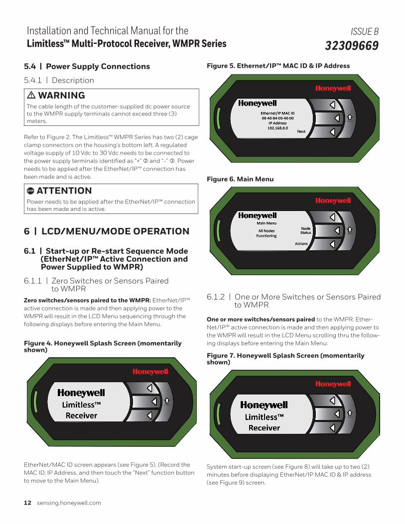
6.1.1 | Zero Switches or Sensors Paired to WMPRZero switches/sensors paired to the WMPR: EtherNet/IP™ active connection is made and then applying power to the WMPR will result in the LCD Menu sequencing through the following displays before entering the Main Menu.
Figure 4. Honeywell Splash Screen (momentarily shown)
EtherNet/MAC ID screen appears (see Figure 5). (Record the MAC ID, IP Address, and then touch the “Next” function button to move to the Main Menu).
Figure 5. Ethernet/IP ™ MAC ID & IP Address
Figure 6. Main Menu
6.1.2 | One or More Switches or Sensors Paired to WMPR
One or more switches/sensors paired to the WMPR: Ether-Net/IP™ active connection is made and then applying power to the WMPR will result in the LCD Menu scrolling thru the follow-ing displays before entering the Main Menu:
Figure 7. Honeywell Splash Screen (momentarily shown)
System start-up screen (see Figure 8) will take up to two (2) minutes before displaying EtherNet/IP MAC ID & IP address (see Figure 9) screen.
Sensing and Internet of Things 13
Installation and Technical Manual for the Limitless™ Multi-Protocol Receiver, WMPR Series
ISSUE B 32309669
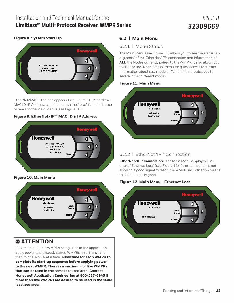
Figure 8. System Start Up
EtherNet/MAC ID screen appears (see Figure 9). (Record the MAC ID, IP Address, and then touch the “Next” function button to move to the Main Menu) (see Figure 10).
Figure 9. EtherNet/IP™ MAC ID & IP Address
Figure 10. Main Menu
, ATTENTIONIf there are multiple WMPRs being used in the application, apply power to previously paired WMPRs first (if any) and then to one WMPR at a time. Allow time for each WMPR to complete its start-up sequence before applying power to the next WMPR. There is a maximum of five WMPRs that can be used in the same localized area. Contact Honeywell Application Engineering at 800-537-6945 if more than five WMPRs are desired to be used in the same localized area.
6.2 | Main Menu
6.2.1 | Menu StatusThe Main Menu (see Figure 11) allows you to see the status “at-a-glance” of the EtherNet/IP™ connection and information of ALL the Nodes currently paired to the WMPR. It also allows you to choose the “Node Status” menu for quick access to further information about each node or “Actions” that routes you to several other different modes.
Figure 11. Main Menu
6.2.2 | EtherNet/IP™ ConnectionEtherNet/IP™ connection: The Main Menu display will in-dicate “Ethernet Lost” (see Figure 12) if the connection is not allowing a good signal to reach the WMPR; no indication means the connection is good.
Figure 12. Main Menu - Ethernet Lost
14 sensing.honeywell.com
Installation and Technical Manual for the Limitless™ Multi-Protocol Receiver, WMPR Series
ISSUE B 32309669
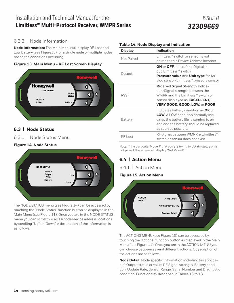
6.2.3 | Node InformationNode Information: The Main Menu will display RF Lost and Low Battery (see Figure13) for a single node or multiple nodes based the conditions occurring.
Figure 13. Main Menu - RF Lost Screen Display
6.3 | Node Status
6.3.1 | Node Status Menu
Figure 14. Node Status
The NODE STATUS menu (see Figure 14) can be accessed by touching the “Node Status” function button as displayed in the Main Menu (see Figure 11). Once you are in the NODE STATUS menu you can scroll thru all 14 node/device address locations by scrolling “Up” or “Down”. A description of the information is as follows:
Table 14. Node Display and IndicationDisplay Indication
Not PairedLimitless™ switch or sensor is not paired to this Device Address location
Output:
ON or OFF status for a Digital in-put-Limitless™ switch Pressure value and Unit type for An-alog sensor-Limitless™ pressure sensor
RSSI:
Received Signal Strength Indica-tion-Signal strength between the WMPR and the Limitless™ switch or sensor displayed as EXCELLENT, VERY GOOD, GOOD, LOW, or POOR
Battery
Indicates battery condition as OK or LOW; A LOW condition normally indi-cates the battery life is coming to an end and the battery should be replaced as soon as possible.
RF LostRF Signal between WMPR & Limitless™ switch or sensor does not exist
Note: If the particular Node # that you are trying to obtain status on is not paired, the screen will display “Not Paired”.
6.4 | Action Menu
6.4.1 | Action Menu
Figure 15. Action Menu
The ACTIONS MENU (see Figure 15) can be accessed by touching the “Actions” function button as displayed in the Main Menu (see Figure 11). Once you are in the ACTION MENU you can choose between several different actions: A description of the actions are as follows:
Node Detail: Node specific information including (as applica-ble) Output status or value, RF Signal strength, Battery condi-tion, Update Rate, Sensor Range, Serial Number and Diagnostic condition. Functionality described in Tables 16 to 18.
Sensing and Internet of Things 15
Installation and Technical Manual for the Limitless™ Multi-Protocol Receiver, WMPR Series
ISSUE B 32309669
Configuration Menu: Allows you to take action to Pair or Purge Nodes, Change Update Rate or Node LCD Display Time, or Reset to WMPR to Factory Defaults. Functionality described in Section 8.6
Receiver Detail: Receiver information specific the WMPR device which includes WMPR FirmWare revision, Part Number, Radio FirmWare revision, Radio MAC ID, and Radio Transmit Power. Functionality described in Section 8.7
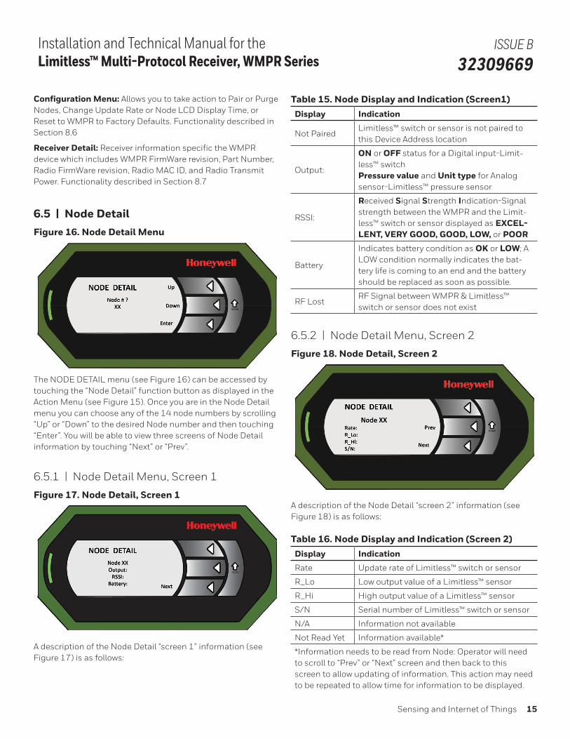
6.5 | Node DetailFigure 16. Node Detail Menu
The NODE DETAIL menu (see Figure 16) can be accessed by touching the “Node Detail” function button as displayed in the Action Menu (see Figure 15). Once you are in the Node Detail menu you can choose any of the 14 node numbers by scrolling “Up” or “Down” to the desired Node number and then touching “Enter”. You will be able to view three screens of Node Detail information by touching “Next” or “Prev”.
6.5.1 | Node Detail Menu, Screen 1
Figure 17. Node Detail, Screen 1
A description of the Node Detail “screen 1” information (see Figure 17) is as follows:
Table 15. Node Display and Indication (Screen1)Display Indication
Not PairedLimitless™ switch or sensor is not paired to this Device Address location
Output:
ON or OFF status for a Digital input-Limit-less™ switch Pressure value and Unit type for Analog sensor-Limitless™ pressure sensor
RSSI:
Received Signal Strength Indication-Signal strength between the WMPR and the Limit-less™ switch or sensor displayed as EXCEL-LENT, VERY GOOD, GOOD, LOW, or POOR
Battery
Indicates battery condition as OK or LOW; A LOW condition normally indicates the bat-tery life is coming to an end and the battery should be replaced as soon as possible.
RF LostRF Signal between WMPR & Limitless™ switch or sensor does not exist
6.5.2 | Node Detail Menu, Screen 2
Figure 18. Node Detail, Screen 2
A description of the Node Detail “screen 2” information (see Figure 18) is as follows:
Table 16. Node Display and Indication (Screen 2)Display Indication
Rate Update rate of Limitless™ switch or sensor
R_Lo Low output value of a Limitless™ sensor
R_Hi High output value of a Limitless™ sensor
S/N Serial number of Limitless™ switch or sensor
N/A Information not available
Not Read Yet Information available*
*Information needs to be read from Node: Operator will need to scroll to “Prev” or “Next” screen and then back to this screen to allow updating of information. This action may need to be repeated to allow time for information to be displayed.
16 sensing.honeywell.com
Installation and Technical Manual for the Limitless™ Multi-Protocol Receiver, WMPR Series
ISSUE B 32309669
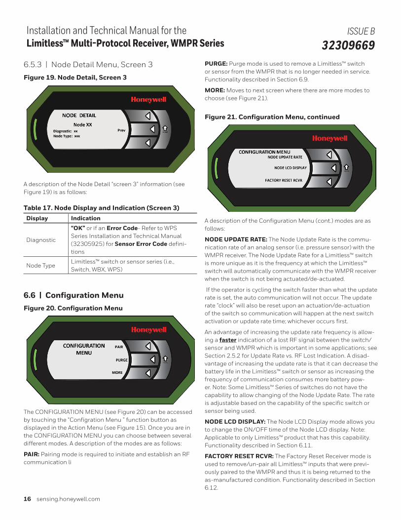
6.5.3 | Node Detail Menu, Screen 3
Figure 19. Node Detail, Screen 3
A description of the Node Detail “screen 3” information (see Figure 19) is as follows:
Table 17. Node Display and Indication (Screen 3)Display Indication
Diagnostic
“OK” or if an Error Code- Refer to WPS Series Installation and Technical Manual (32305925) for Sensor Error Code defini-tions
Node TypeLimitless™ switch or sensor series (i.e., Switch, WBX, WPS)
6.6 | Configuration MenuFigure 20. Configuration Menu
The CONFIGURATION MENU (see Figure 20) can be accessed by touching the “Configration Menu ” function button as displayed in the Action Menu (see Figure 15). Once you are in the CONFIGURATION MENU you can choose between several different modes. A description of the modes are as follows:
PAIR: Pairing mode is required to initiate and establish an RF communication link between each WMPR and a Limitless™ input. Functionality described in Section 6.8.
PURGE: Purge mode is used to remove a Limitless™ switch or sensor from the WMPR that is no longer needed in service. Functionality described in Section 6.9.
MORE: Moves to next screen where there are more modes to choose (see Figure 21).
Figure 21. Configuration Menu, continued
A description of the Configuration Menu (cont.) modes are as follows:
NODE UPDATE RATE: The Node Update Rate is the commu-nication rate of an analog sensor (i.e. pressure sensor) with the WMPR receiver. The Node Update Rate for a Limitless™ switch is more unique as it is the frequency at which the Limitless™ switch will automatically communicate with the WMPR receiver when the switch is not being actuated/de-actuated.
If the operator is cycling the switch faster than what the update rate is set, the auto communication will not occur. The update rate “clock” will also be reset upon an actuation/de-actuation of the switch so communication will happen at the next switch activation or update rate time; whichever occurs first.
An advantage of increasing the update rate frequency is allow-ing a faster indication of a lost RF signal between the switch/sensor and WMPR which is important in some applications; see Section 2.5.2 for Update Rate vs. RF Lost Indication. A disad-vantage of increasing the update rate is that it can decrease the battery life in the Limitless™ switch or sensor as increasing the frequency of communication consumes more battery pow-er. Note: Some Limitless™ Series of switches do not have the capability to allow changing of the Node Update Rate. The rate is adjustable based on the capability of the specific switch or sensor being used.
NODE LCD DISPLAY: The Node LCD Display mode allows you to change the ON/OFF time of the Node LCD display. Note: Applicable to only Limitless™ product that has this capability. Functionality described in Section 6.11.
FACTORY RESET RCVR: The Factory Reset Receiver mode is used to remove/un-pair all Limitless™ inputs that were previ-ously paired to the WMPR and thus it is being returned to the as-manufactured condition. Functionality described in Section 6.12.
Sensing and Internet of Things 17
Installation and Technical Manual for the Limitless™ Multi-Protocol Receiver, WMPR Series
ISSUE B 32309669
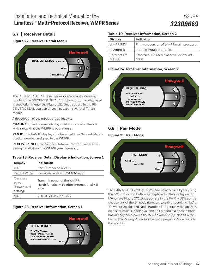
6.7 | Receiver DetailFigure 22. Receiver Detail Menu
The RECEIVER DETAIL (see Figure 22) can be accessed by touching the “RECEIVER DETAIL” function button as displayed in the Action Menu (see Figure 15). Once you are in the RE-CEIVER DETAIL you can choose between several different modes.
A description of the modes are as follows:
CHANNEL: The Channel displays which channel in the 2.4 MHz range that the WMPR is operating at.
PAN ID: The PAN ID displays the Personal Area Network identi-fication number assigned to the WMPR.
RECEIVER INFO: The Receiver Information contains the fol-lowing detail about the WMPR (see Figure 23).
Table 18. Receiver Detail Display & Indication, Screen 1Display Indication
P/N Part Number of WMPR
Radio FW Rev Firmware version in WMPR radio
Transmit power(Power level setting)
Transmit power of the WMPR: North America = 11 dBm; International = 6 dBm
MAC MAC ID of WMPR radio
Figure 23. Receiver Information, Screen 1
Table 19. Receiver Information, Screen 2Display Indication
WMPR REV Firmware version of WMPR main processor
IP Address Internet Protocol address
Enternet IP/ MAC ID
EtherNet/IP™ Media Access Control ad-dress
Figure 24. Receiver Information, Screen 2
6.8 | Pair ModeFigure 25. Pair Mode
The PAIR MODE (see Figure 25) can be accessed by touching the “PAIR” function button as displayed in the Configuration Menu (see Figure 20). Once you are in the PAIR MODE you can choose any of the 14 node numbers to pair by scrolling “Up” or “Down” to the desired Node number. The screen will display the next sequential Node# available to Pair and if a chosen node has already been paired the screen will display “Node Paired”. Follow the Pairing Procedure below to properly Pair a Node to the WMPR:
18 sensing.honeywell.com
Installation and Technical Manual for the Limitless™ Multi-Protocol Receiver, WMPR Series
ISSUE B 32309669
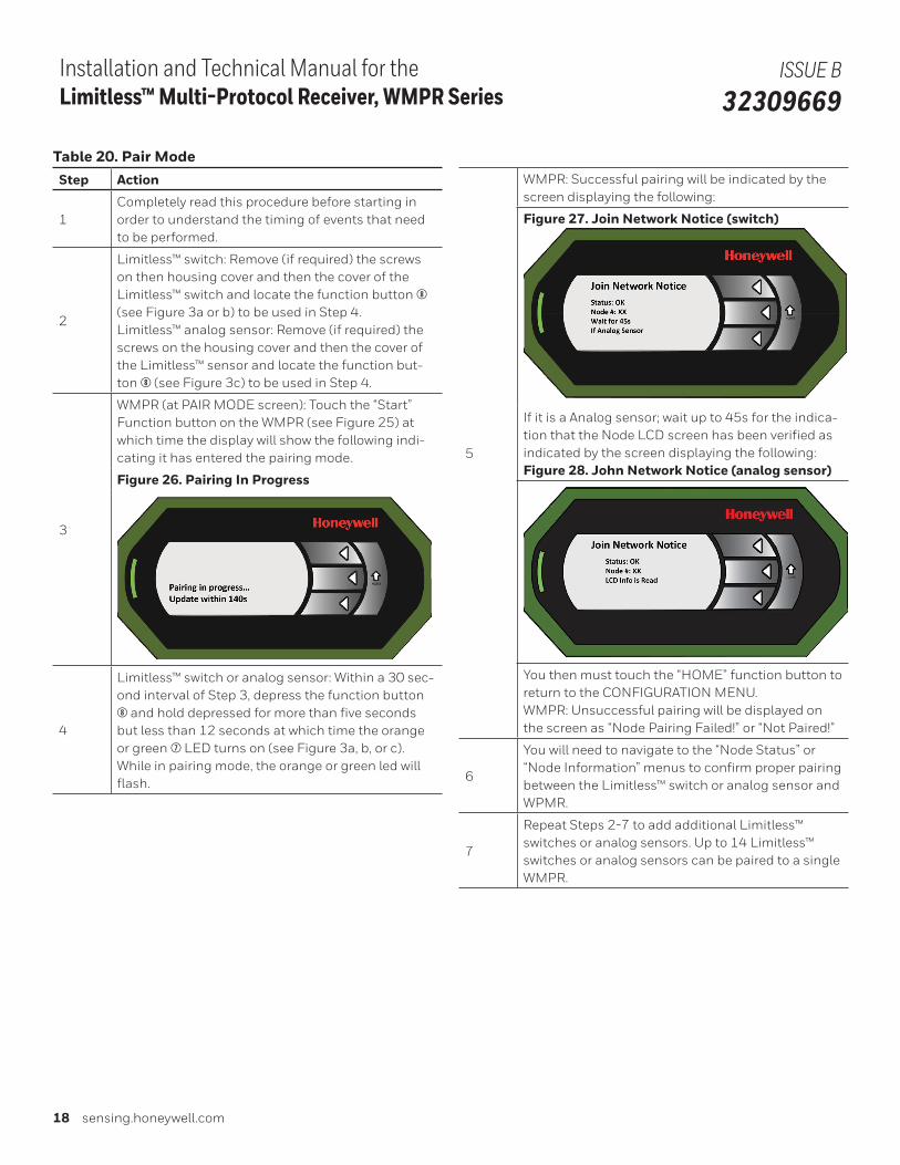
Table 20. Pair ModeStep Action
1Completely read this procedure before starting in order to understand the timing of events that need to be performed.
2
Limitless™ switch: Remove (if required) the screws on then housing cover and then the cover of the Limitless™ switch and locate the function button 8 (see Figure 3a or b) to be used in Step 4.Limitless™ analog sensor: Remove (if required) the screws on the housing cover and then the cover of the Limitless™ sensor and locate the function but-ton 8 (see Figure 3c) to be used in Step 4.
3
WMPR (at PAIR MODE screen): Touch the “Start” Function button on the WMPR (see Figure 25) at which time the display will show the following indi-cating it has entered the pairing mode.
Figure 26. Pairing In Progress
4
Limitless™ switch or analog sensor: Within a 30 sec-ond interval of Step 3, depress the function button 8 and hold depressed for more than five seconds but less than 12 seconds at which time the orange or green 7 LED turns on (see Figure 3a, b, or c). While in pairing mode, the orange or green led will flash.
5
WMPR: Successful pairing will be indicated by the screen displaying the following:
Figure 27. Join Network Notice (switch)
If it is a Analog sensor; wait up to 45s for the indica-tion that the Node LCD screen has been verified as indicated by the screen displaying the following:Figure 28. John Network Notice (analog sensor)
You then must touch the “HOME” function button to return to the CONFIGURATION MENU.WMPR: Unsuccessful pairing will be displayed on the screen as “Node Pairing Failed!” or “Not Paired!”
6
You will need to navigate to the “Node Status” or “Node Information” menus to confirm proper pairing between the Limitless™ switch or analog sensor and WPMR.
7
Repeat Steps 2-7 to add additional Limitless™ switches or analog sensors. Up to 14 Limitless™ switches or analog sensors can be paired to a single WMPR.
Sensing and Internet of Things 19
Installation and Technical Manual for the Limitless™ Multi-Protocol Receiver, WMPR Series
ISSUE B 32309669
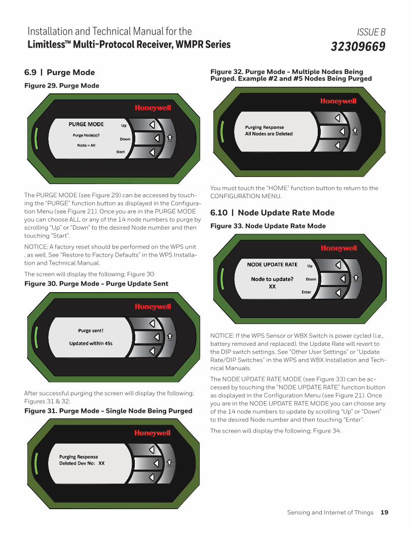
6.9 | Purge ModeFigure 29. Purge Mode
The PURGE MODE (see Figure 29) can be accessed by touch-ing the “PURGE” function button as displayed in the Configura-tion Menu (see Figure 21). Once you are in the PURGE MODE you can choose ALL or any of the 14 node numbers to purge by scrolling “Up” or “Down” to the desired Node number and then touching “Start”.
NOTICE: A factory reset should be performed on the WPS unit , as well. See “Restore to Factory Defaults” in the WPS Installa-tion and Technical Manual.
The screen will display the following; Figure 30:
Figure 30. Purge Mode - Purge Update Sent
After successful purging the screen will display the following; Figures 31 & 32:
Figure 31. Purge Mode - Single Node Being Purged
Figure 32. Purge Mode - Multiple Nodes Being Purged. Example #2 and #5 Nodes Being Purged
You must touch the “HOME” function button to return to the CONFIGURATION MENU.
6.10 | Node Update Rate ModeFigure 33. Node Update Rate Mode
NOTICE: If the WPS Sensor or WBX Switch is power cycled (i.e., battery removed and replaced), the Update Rate will revert to the DIP switch settings. See “Other User Settings” or “Update Rate/DIP Switches” in the WPS and WBX Installation and Tech-nical Manuals.
The NODE UPDATE RATE MODE (see Figure 33) can be ac-cessed by touching the “NODE UPDATE RATE” function button as displayed in the Configuration Menu (see Figure 21). Once you are in the NODE UPDATE RATE MODE you can choose any of the 14 node numbers to update by scrolling “Up” or “Down” to the desired Node number and then touching “Enter”.
The screen will display the following; Figure 34:
20 sensing.honeywell.com
Installation and Technical Manual for the Limitless™ Multi-Protocol Receiver, WMPR Series
ISSUE B 32309669
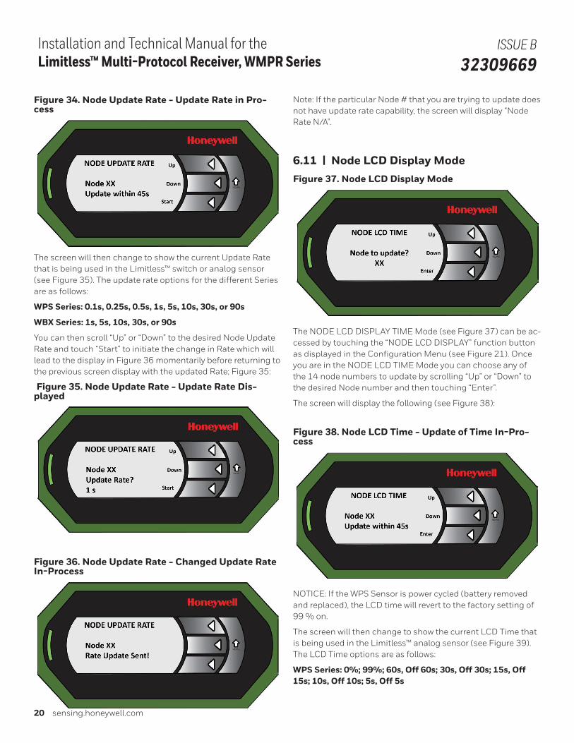
Figure 34. Node Update Rate - Update Rate in Pro-cess
The screen will then change to show the current Update Rate that is being used in the Limitless™ switch or analog sensor (see Figure 35). The update rate options for the different Series are as follows:
WPS Series: 0.1s, 0.25s, 0.5s, 1s, 5s, 10s, 30s, or 90s
WBX Series: 1s, 5s, 10s, 30s, or 90s
You can then scroll “Up” or “Down” to the desired Node Update Rate and touch “Start” to initiate the change in Rate which will lead to the display in Figure 36 momentarily before returning to the previous screen display with the updated Rate; Figure 35:
Figure 35. Node Update Rate - Update Rate Dis-played
Figure 36. Node Update Rate - Changed Update Rate In-Process
Note: If the particular Node # that you are trying to update does not have update rate capability, the screen will display “Node Rate N/A”.
6.11 | Node LCD Display ModeFigure 37. Node LCD Display Mode
The NODE LCD DISPLAY TIME Mode (see Figure 37) can be ac-cessed by touching the “NODE LCD DISPLAY” function button as displayed in the Configuration Menu (see Figure 21). Once you are in the NODE LCD TIME Mode you can choose any of the 14 node numbers to update by scrolling “Up” or “Down” to the desired Node number and then touching “Enter”.
The screen will display the following (see Figure 38):
Figure 38. Node LCD Time - Update of Time In-Pro-cess
NOTICE: If the WPS Sensor is power cycled (battery removed and replaced), the LCD time will revert to the factory setting of 99 % on.
The screen will then change to show the current LCD Time that is being used in the Limitless™ analog sensor (see Figure 39). The LCD Time options are as follows:
WPS Series: 0%; 99%; 60s, Off 60s; 30s, Off 30s; 15s, Off 15s; 10s, Off 10s; 5s, Off 5s
Sensing and Internet of Things 21
Installation and Technical Manual for the Limitless™ Multi-Protocol Receiver, WMPR Series
ISSUE B 32309669
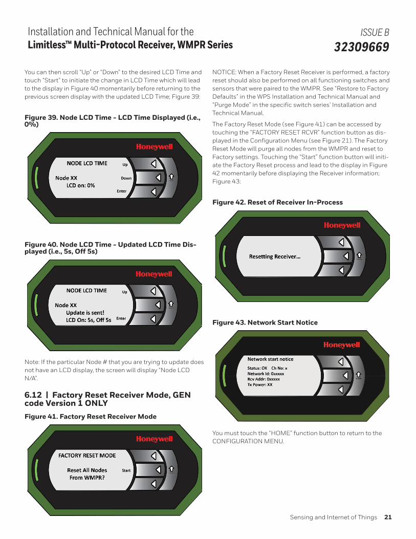
You can then scroll “Up” or “Down” to the desired LCD Time and touch “Start” to initiate the change in LCD Time which will lead to the display in Figure 40 momentarily before returning to the previous screen display with the updated LCD Time; Figure 39:
Figure 39. Node LCD Time - LCD Time Displayed (i.e., 0%)
Figure 40. Node LCD Time - Updated LCD Time Dis-played (i.e., 5s, Off 5s)
Note: If the particular Node # that you are trying to update does not have an LCD display, the screen will display “Node LCD N/A”.
6.12 | Factory Reset Receiver Mode, GEN code Version 1 ONLYFigure 41. Factory Reset Receiver Mode
NOTICE: When a Factory Reset Receiver is performed, a factory reset should also be performed on all functioning switches and sensors that were paired to the WMPR. See “Restore to Factory Defaults” in the WPS Installation and Technical Manual and “Purge Mode” in the specific switch series’ Installation and Technical Manual.
The Factory Reset Mode (see Figure 41) can be accessed by touching the “FACTORY RESET RCVR” function button as dis-played in the Configuration Menu (see Figure 21). The Factory Reset Mode will purge all nodes from the WMPR and reset to Factory settings. Touching the “Start” function button will initi-ate the Factory Reset process and lead to the display in Figure 42 momentarily before displaying the Receiver information; Figure 43:
Figure 42. Reset of Receiver In-Process
Figure 43. Network Start Notice
You must touch the “HOME” function button to return to the CONFIGURATION MENU.
22 sensing.honeywell.com
Installation and Technical Manual for the Limitless™ Multi-Protocol Receiver, WMPR Series
ISSUE B 32309669
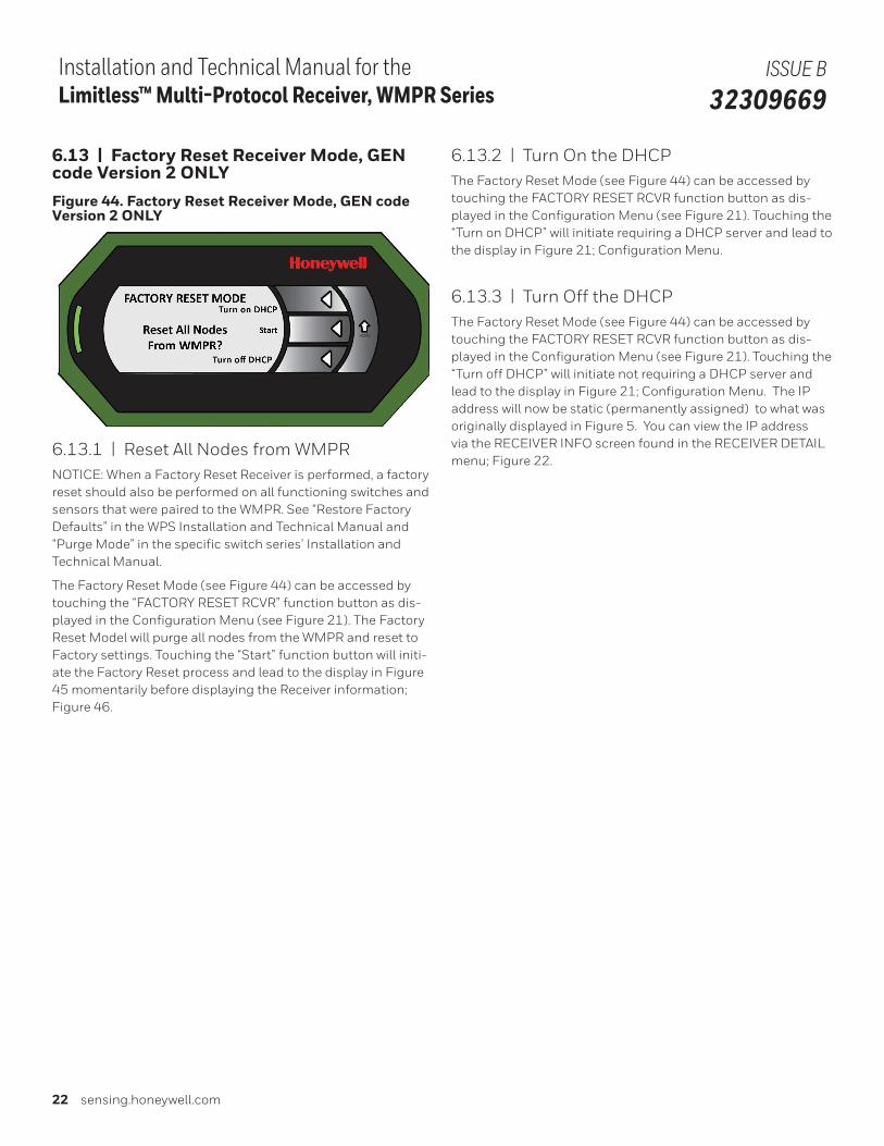
6.13 | Factory Reset Receiver Mode, GEN code Version 2 ONLYFigure 44. Factory Reset Receiver Mode, GEN code Version 2 ONLY
6.13.1 | Reset All Nodes from WMPRNOTICE: When a Factory Reset Receiver is performed, a factory reset should also be performed on all functioning switches and sensors that were paired to the WMPR. See “Restore Factory Defaults” in the WPS Installation and Technical Manual and “Purge Mode” in the specific switch series’ Installation and Technical Manual.
The Factory Reset Mode (see Figure 44) can be accessed by touching the “FACTORY RESET RCVR” function button as dis-played in the Configuration Menu (see Figure 21). The Factory Reset Model will purge all nodes from the WMPR and reset to Factory settings. Touching the “Start” function button will initi-ate the Factory Reset process and lead to the display in Figure 45 momentarily before displaying the Receiver information; Figure 46.
6.13.2 | Turn On the DHCPThe Factory Reset Mode (see Figure 44) can be accessed by touching the FACTORY RESET RCVR function button as dis-played in the Configuration Menu (see Figure 21). Touching the “Turn on DHCP” will initiate requiring a DHCP server and lead to the display in Figure 21; Configuration Menu.
6.13.3 | Turn Off the DHCPThe Factory Reset Mode (see Figure 44) can be accessed by touching the FACTORY RESET RCVR function button as dis-played in the Configuration Menu (see Figure 21). Touching the “Turn off DHCP” will initiate not requiring a DHCP server and lead to the display in Figure 21; Configuration Menu. The IP address will now be static (permanently assigned) to what was originally displayed in Figure 5. You can view the IP address via the RECEIVER INFO screen found in the RECEIVER DETAIL menu; Figure 22.
Sensing and Internet of Things 23
Installation and Technical Manual for the Limitless™ Multi-Protocol Receiver, WMPR Series
ISSUE B 32309669
7 | ANTENNA, CABLE, & MOUNTING OPTIONS
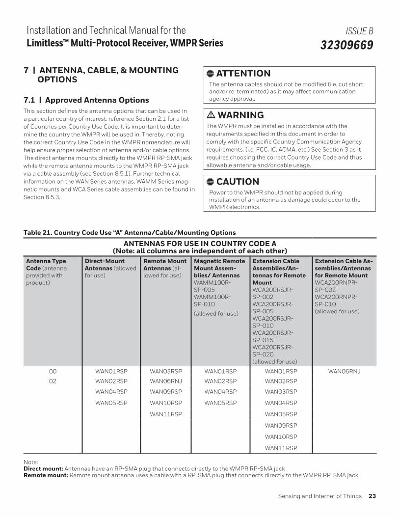
7.1 | Approved Antenna OptionsThis section defines the antenna options that can be used in a particular country of interest; reference Section 2.1 for a list of Countries per Country Use Code. It is important to deter-mine the country the WMPR will be used in. Thereby, noting the correct Country Use Code in the WMPR nomenclature will help ensure proper selection of antenna and/or cable options. The direct antenna mounts directly to the WMPR RP-SMA jack while the remote antenna mounts to the WMPR RP-SMA jack via a cable assembly (see Section 8.5.1). Further technical information on the WAN Series antennas, WAMM Series mag-netic mounts and WCA Series cable assemblies can be found in Section 8.5.3.
, ATTENTIONThe antenna cables should not be modified (i.e. cut short and/or re-terminated) as it may affect communication agency approval.
m WARNINGThe WMPR must be installed in accordance with the requirements specified in this document in order to comply with the specific Country Communication Agency requirements. (i.e. FCC, IC, ACMA, etc.) See Section 3 as it requires choosing the correct Country Use Code and thus allowable antenna and/or cable usage.
, CAUTIONPower to the WMPR should not be applied during installation of an antenna as damage could occur to the WMPR electronics.
Table 21. Country Code Use “A” Antenna/Cable/Mounting Options
ANTENNAS FOR USE IN COUNTRY CODE A(Note: all columns are independent of each other)
Antenna Type Code (antenna provided with product)
Direct-Mount Antennas (allowed for use)
Remote Mount Antennas (al-lowed for use)
Magnetic Remote Mount Assem-blies/ Antennas WAMM100R-SP-005WAMM100R-SP-010
(allowed for use)
Extension Cable Assemblies/An-tennas for Remote MountWCA200RSJR-SP-002WCA200RSJR-SP-005WCA200RSJR-SP-010WCA200RSJR-SP-015WCA200RSJR-SP-020(allowed for use)
Extension Cable As-semblies/Antennas for Remote MountWCA200RNPR-SP-002WCA200RNPR-SP-010(allowed for use)
00 WAN01RSP WAN03RSP WAN01RSP WAN01RSP WAN06RNJ
02 WAN02RSP WAN06RNJ WAN02RSP WAN02RSP
WAN04RSP WAN09RSP WAN04RSP WAN03RSP
WAN05RSP WAN10RSP WAN05RSP WAN04RSP
WAN11RSP WAN05RSP
WAN09RSP
WAN10RSP
WAN11RSP
Note: Direct mount: Antennas have an RP-SMA plug that connects directly to the WMPR RP-SMA jackRemote mount: Remote mount antenna uses a cable with a RP-SMA plug that connects directly to the WMPR RP-SMA jack
24 sensing.honeywell.com
Installation and Technical Manual for the Limitless™ Multi-Protocol Receiver, WMPR Series
ISSUE B 32309669
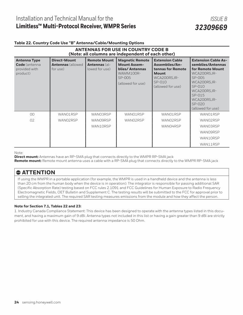
Table 22. Country Code Use “B” Antenna/Cable/Mounting Options
ANTENNAS FOR USE IN COUNTRY CODE B(Note: all columns are independent of each other)
Antenna Type Code (antenna provided with product)
Direct-Mount Antennas (allowed for use)
Remote Mount Antennas (al-lowed for use)
Magnetic Remote Mount Assem-blies/ Antennas WAMM100R-SP-005
(allowed for use)
Extension Cable Assemblies/An-tennas for Remote MountWCA200RSJR-SP-010(allowed for use)
Extension Cable As-semblies/Antennas for Remote MountWCA200RSJR-SP-005WCA200RSJR-SP-010WCA200RSJR-SP-015WCA200RSJR-SP-020(allowed for use)
00 WAN01RSP WAN03RSP WAN01RSP WAN01RSP WAN01RSP
02 WAN02RSP WAN09RSP WAN02RSP WAN02RSP WAN02RSP
WAN10RSP WAN04RSP WAN03RSP
WAN09RSP
WAN10RSP
WAN11RSP
Note: Direct mount: Antennas have an RP-SMA plug that connects directly to the WMPR RP-SMA jackRemote mount: Remote mount antenna uses a cable with a RP-SMA plug that connects directly to the WMPR RP-SMA jack
, ATTENTIONIf using the WMPR in a portable application (for example, the WMPR is used in a handheld device and the antenna is less than 20 cm from the human body when the device is in operation): The integrator is responsible for passing additional SAR (Specific Absorption Rate) testing based on FCC rules 2.1091 and FCC Guidelines for Human Exposure to Radio Frequency Electromagnetic Fields, OET Bulletin and Supplement C. The testing results will be submitted to the FCC for approval prior to selling the integrated unit. The required SAR testing measures emissions from the module and how they affect the person.
Note for Section 7.1, Tables 22 and 23: 1. Industry Canada Compliance Statement: This device has been designed to operate with the antenna types listed in this docu-ment, and having a maximum gain of 9 dBi. Antenna types not included in this list or having a gain greater than 9 dBi are strictly prohibited for use with this device. The required antenna impedance is 50 Ohm.
Sensing and Internet of Things 25
Installation and Technical Manual for the Limitless™ Multi-Protocol Receiver, WMPR Series
ISSUE B 32309669
8 | ANTENNA SELECTION, ADJUSTMENT, AND MOUNTING
8.1 | Warnings
8.1.1 General Installation Warnings
, ATTENTION• Professional Installation is required to ensure conformity
with Federal Communications Commission (FCC) in the USA and Industry Canada (IC) in Canada.
• Professional installation is required for the selection and installation of approved antennas and setup of the maximum allowable radiated power from the Limitless™ WMPR Series as configured for the particular installation site.
• The antenna used for this sensor must be installed to provide a separation distance of at least 20 cm [7.87 in] from all persons and must not be co-located or operating in conjunction with any other antenna or sensor.
• For remote antenna, see antenna installation require-ments to satisfy FCC RF exposure requirements.
, ATTENTIONFederal Communications Commission (FCC):
• The Limitless™ WMPR Series complies with part 15 of the FCC rules. Operation is subject to the following two conditions: (1) this device may not cause harmful inter-ference, and (2) this device must accept any interference received, including interference that may cause unde-sired operation.
Industry Canada (IC):
• L’installateur de cette radio doit s’assurer que l’antenne est située ou orientée de manière à ne pas émettre de radiofréquences excédant les limites permises par Santé Canada pour la population générale. Veuillez consulter le Code de sécurité 6 de Santé Canada au www.hc-sc.gc.ca/rpb.
8.1.2 Outdoor Installation Warnings
m WARNINGLIVES MAY BE AT RISK! Carefully observe these instructions and any special instructions included with the equipment being installed.
m WARNINGCONTACTING POWER LINES COULD BE FATALLook over the site before beginning any installation and anticipate possible hazards, especially these:
• Make sure no power lines are near where possible con-tact can be made. Antennas, masts, towers, guy wires, or cables may lean or fall and contact these lines. People may be injured or killed if they are touching or holding any part of equipment when it contacts electric lines. Make sure there is NO possibility that equipment or personnel can come in contact directly or indirectly with power lines.
• Assume all overhead lines are power lines.• The horizontal distance from a tower, mast, or antenna to
the nearest power line should be at least twice the total length of the mast/antenna combination. This will ensure that the mast will not contact power if it falls during either installation or later.
m WARNINGTO AVOID FALLING, USE SAFE PROCEDURES WHEN WORKING AT HEIGHTS ABOVE GROUND
• Select equipment locations that will allow safe, simple equipment installation
• Don’t work alone. A friend or co-worker can save a life if an accident happens.
• Use approved, non-conducting ladders and other safety equipment. Make sure all equipment is in good repair.
• If a tower or mast begins falling, don’t attempt to catch it. Stand back and let it fall.
• If anything such as a wire or mast does come in contact with a power line, DON’T TOUCH IT OR ATTEMPT TO MOVE IT. Instead, save a life by calling the power compa-ny.
• Don’t attempt to erect antennas or towers on windy days.
m WARNINGMAKE SURE ALL TOWERS AND MASTS ARE SECURELY GROUNDED, AND ELECTRICAL CABLES CONNECTED TO ANTENNAS HAVE LIGHTNING ARRESTORS.This will help prevent fire damage or human injury in case of lightning, static build up, or short circuit within equipment connected to antenna.
• The base of the antenna mast or tower must be connect-ed directly to the building protective ground or to one-or-more approved grounding rods, using 1 AWG ground wire and corrosion-resistant connectors.
• Refer to the National Electrical Code for grounding de-tails.
• Lightning arrestors for antenna feed coaxial cables are available from electrical supply houses.
26 sensing.honeywell.com
Installation and Technical Manual for the Limitless™ Multi-Protocol Receiver, WMPR Series
ISSUE B 32309669
m WARNINGIf a person comes in contact with electrical power, and cannot moveDO NOT TOUCH THAT PERSON OR RISK ELECTROCUTION.
• Use a non-conductive dry board, stick, or rope to push, pull, or drag them so they no longer are in contact with electrical power.
• Once they are no longer contacting electrical power, administer CPR if certified, and make sure emergency medical aid has been requested.
8.2 | Antenna Designs and Considerations
8.2.1 Omni-directional Antenna Design
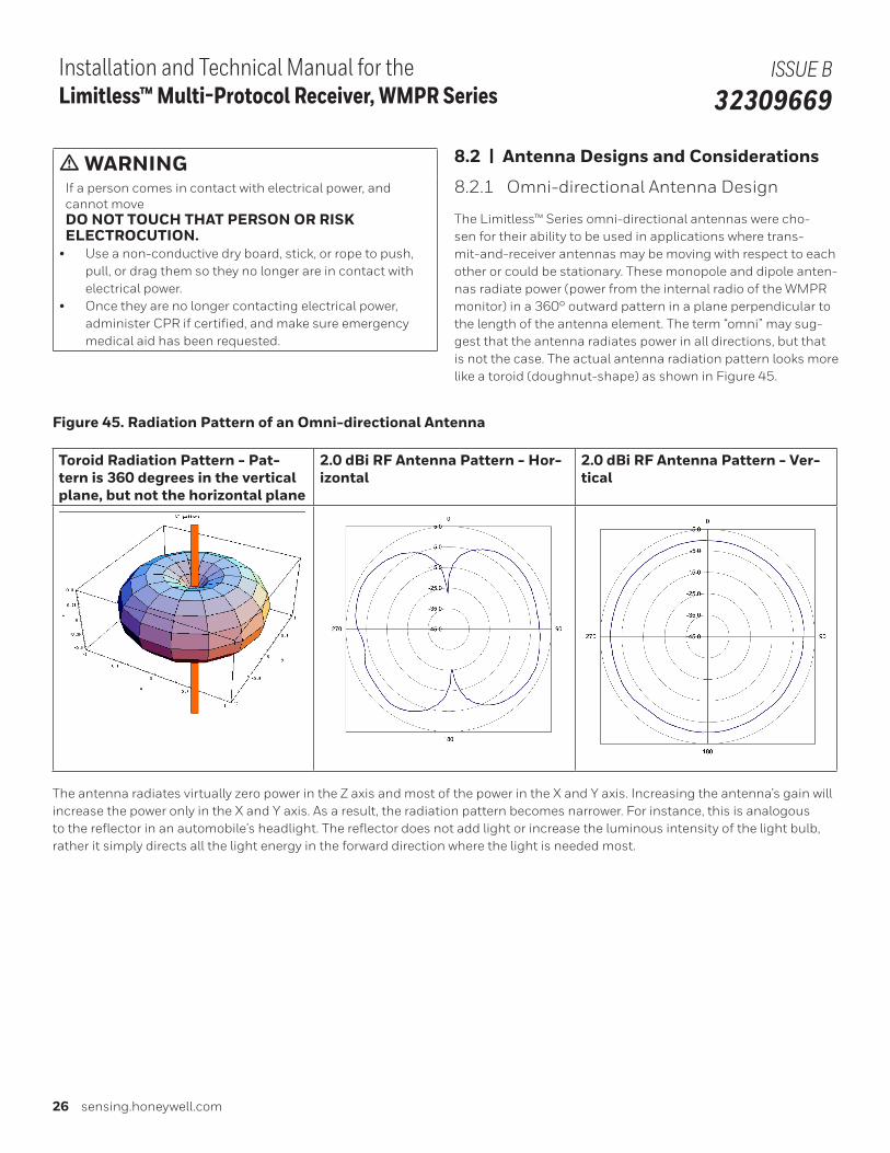
The Limitless™ Series omni-directional antennas were cho-sen for their ability to be used in applications where trans-mit-and-receiver antennas may be moving with respect to each other or could be stationary. These monopole and dipole anten-nas radiate power (power from the internal radio of the WMPR monitor) in a 360° outward pattern in a plane perpendicular to the length of the antenna element. The term “omni” may sug-gest that the antenna radiates power in all directions, but that is not the case. The actual antenna radiation pattern looks more like a toroid (doughnut-shape) as shown in Figure 45.
Figure 45. Radiation Pattern of an Omni-directional Antenna
Toroid Radiation Pattern - Pat-tern is 360 degrees in the vertical plane, but not the horizontal plane
2.0 dBi RF Antenna Pattern - Hor-izontal
2.0 dBi RF Antenna Pattern - Ver-tical
The antenna radiates virtually zero power in the Z axis and most of the power in the X and Y axis. Increasing the antenna’s gain will increase the power only in the X and Y axis. As a result, the radiation pattern becomes narrower. For instance, this is analogous to the reflector in an automobile’s headlight. The reflector does not add light or increase the luminous intensity of the light bulb, rather it simply directs all the light energy in the forward direction where the light is needed most.
Sensing and Internet of Things 27
Installation and Technical Manual for the Limitless™ Multi-Protocol Receiver, WMPR Series
ISSUE B 32309669
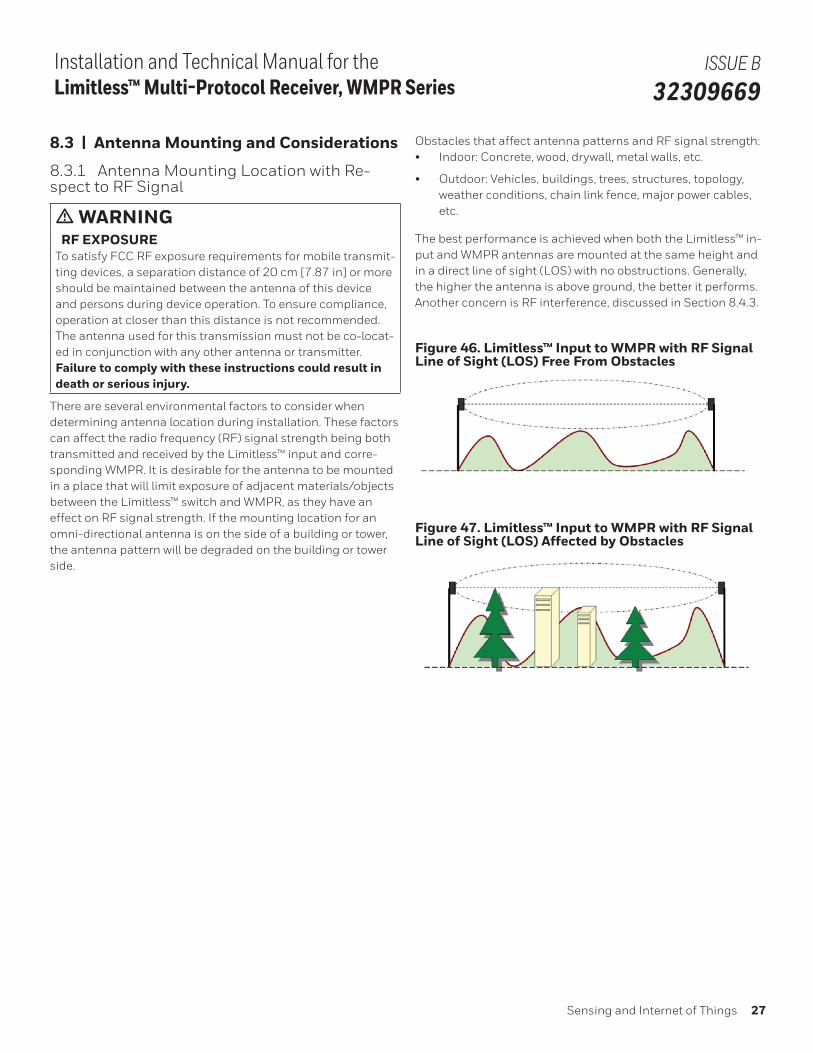
8.3 | Antenna Mounting and Considerations
8.3.1 Antenna Mounting Location with Re-spect to RF Signal
m WARNINGRF EXPOSURE
To satisfy FCC RF exposure requirements for mobile transmit-ting devices, a separation distance of 20 cm [7.87 in] or more should be maintained between the antenna of this device and persons during device operation. To ensure compliance, operation at closer than this distance is not recommended. The antenna used for this transmission must not be co-locat-ed in conjunction with any other antenna or transmitter.Failure to comply with these instructions could result in death or serious injury.
There are several environmental factors to consider when determining antenna location during installation. These factors can affect the radio frequency (RF) signal strength being both transmitted and received by the Limitless™ input and corre-sponding WMPR. It is desirable for the antenna to be mounted in a place that will limit exposure of adjacent materials/objects between the Limitless™ switch and WMPR, as they have an effect on RF signal strength. If the mounting location for an omni-directional antenna is on the side of a building or tower, the antenna pattern will be degraded on the building or tower side.
Obstacles that affect antenna patterns and RF signal strength:• Indoor: Concrete, wood, drywall, metal walls, etc.
• Outdoor: Vehicles, buildings, trees, structures, topology, weather conditions, chain link fence, major power cables, etc.
The best performance is achieved when both the Limitless™ in-put and WMPR antennas are mounted at the same height and in a direct line of sight (LOS) with no obstructions. Generally, the higher the antenna is above ground, the better it performs. Another concern is RF interference, discussed in Section 8.4.3.
Figure 46. Limitless™ Input to WMPR with RF Signal Line of Sight (LOS) Free From Obstacles
Figure 47. Limitless™ Input to WMPR with RF Signal Line of Sight (LOS) Affected by Obstacles
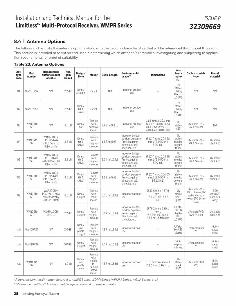
28 sensing.honeywell.com
Installation and Technical Manual for the Limitless™ Multi-Protocol Receiver, WMPR Series
ISSUE B 32309669
8.4 | Antenna OptionsThe following chart lists the antenna options along with the various characteristics that will be referenced throughout this section. This section is intended to assist an end user in determining which antenna(s) are worth investigating and subjecting to applica-tion requirements for proof of suitability.
Table 23. Antenna Options
Ant.type code
Part number
Replacement antenna mount
or cable
Ant. gain
(max.)Design/
Style Mount Cable Length Environmental usage** Dimensions
An-tenna mate-
rial
Cable material/ type
Mount material
01 WAN01RSP N/A 2.2 dBi Omni/Straight Direct N/A Indoor or outdoor
use –
UV stable LG Key flex BT-1040D
N/A N/A
02 WAN02RSP N/A 2.2 dBiOmni/ tilt &
swivelDirect N/A Indoor or outdoor
use –
UV stable LG Key flex BT-1040D
N/A N/A
03 WAN03R-SP N/A 3.0 dBi Omni/
flat
Remote with
adhesive mount
2,99 m [9.8 ft] Indoor or outdoor use
115 mm L x 22,1 mm W x 4,57 mm D [4.53 in L x 0.87 in W x 0.18 in D] 3 m [9.8 ft] cable
UV stable
ABS
UV stable PVC/ RG-174 coax N/A
04 WAN04R-SP
WAMM100R-SP-005 base
with 1,52 m [5 ft] of cable
5.5 dBi Omni/ tilt &
swivel
Remote with
magnet-ic mount
1,52 m [5 ft]
Indoor or limited outdoor exposure. Protect against direct rain, salt, snow, ice, etc.
Ø 12,7 mm x 208,28 mm L [Ø 0.50 in x
8.20 in L]
UV stable
molded polyure-
thane
UV stable PVC/ RG-174 coax
UV stable black ABS
05 WAN04R-SP
WAMM100R-SP-010 base
with 3,05 m [10 ft] of cable
5.5 dBi Omni/ tilt &
swivel
Remote with
magnet-ic mount
3,04 m [10 ft]
Indoor or limited outdoor exposure. Protect against direct rain, salt, snow, ice, etc.
Ø 12,7 mm x 208,28 mm L [Ø 0.50 in x
8.20 in L]
UV stable
molded polyure-
thane
UV stable PVC/ RG-174 coax
UV stable black ABS
06 WAN05R-SP
WAMM100R-SP-005 base
with 1,52 m [5 ft] of cable
9.0 dBi Omni/ tilt &
swivel
Remote with
magnet-ic mount
1,52 m [5 ft]
Indoor or limited outdoor exposure. Protect against direct rain, salt, snow, ice, etc.
Ø 12,7 mm x 384,05 mm L [Ø 0.50 in x
15.12 in L]
UV stable
molded polyure-
thane
UV stable PVC/ RG-174 coax
UV stable black ABS
09 WAN06R-SP
WCA200RN-PRSP-010 coax cable assembly 3,05 m [10 ft]
8.0 dBi Omni/ straight
Remote with mast
mount
3,35 m [11 ft] Indoor or outdoor use
Ø 33,5 mm x 427,9 mm L
[Ø 1.32 in x 16.85 in L]
UV stable fiber-glass
UV stable PVC/RG-316 coax, UV
stable Polyeth-ylene/200 Series
coax
300 series SST aluminum
alloy
10 WAN02R-SP
WAMM100R-SP-010 2.2 dBi Omni/
straight
Remote with
magnet-ic mount
3,04 m [10 ft]
Indoor or limited outdoor exposure. Protect against direct rain, salt, snow, ice, etc.
Ø 76,2 mm x 230,1 mm L
[Ø 3.0 in x 9.06 in L] 4,57 m [15 ft] cable
UV sta-ble LG Keyflex
BT-1040D
UV stable PVC/RG-174 coax
UV stable black ABS
n/a WAN09RSP N/A 3.0 dBi
Omni/ low
profile straight
Remote with
magnet-ic mount
4,57 m [15 ft] Indoor or outdoor use –
UV sta-ble ABS plastic
UV stable black PVC
Nickel-plated steel
n/a WAN10RSP N/A 5.0 dBi Omni/ straight
Remote with
magnet-ic mount
4,57 m [15 ft] Indoor or outdoor use –
Nick-el-plat-ed steel
UV stable black PVC
Nickel-plated steel
n/a WAN11R-SP N/A 4.0 dBi
Omni/ low
profile dome
Remote with
mobile th-
ru-hole screw mount
4,57 m [15 ft] Indoor or outdoor use
Ø 39 mm x 42,4 mm L [Ø 1.54 in x 1.67 in L ]
UV stable black PVC
UV stable black PVC
Nickel-plated steel
*Reference Limitless™ nomenclature (i.e. WMPR Series, WDRR Series, WPMM Series, WGLA Series, etc.)
**Reference Limitless™ Environment Usage section 8.4 for further details
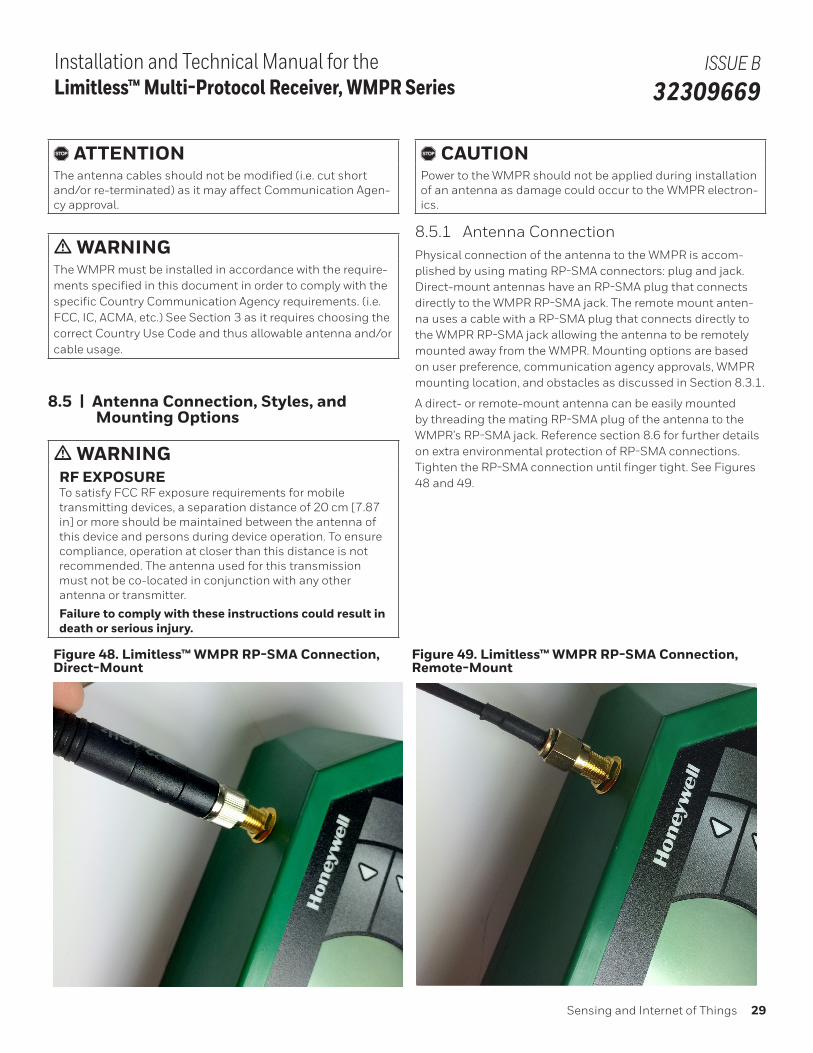
Sensing and Internet of Things 29
Installation and Technical Manual for the Limitless™ Multi-Protocol Receiver, WMPR Series
ISSUE B 32309669
, ATTENTIONThe antenna cables should not be modified (i.e. cut short and/or re-terminated) as it may affect Communication Agen-cy approval.
m WARNINGThe WMPR must be installed in accordance with the require-ments specified in this document in order to comply with the specific Country Communication Agency requirements. (i.e. FCC, IC, ACMA, etc.) See Section 3 as it requires choosing the correct Country Use Code and thus allowable antenna and/or cable usage.
8.5 | Antenna Connection, Styles, and Mounting Options
m WARNINGRF EXPOSURE To satisfy FCC RF exposure requirements for mobile transmitting devices, a separation distance of 20 cm [7.87 in] or more should be maintained between the antenna of this device and persons during device operation. To ensure compliance, operation at closer than this distance is not recommended. The antenna used for this transmission must not be co-located in conjunction with any other antenna or transmitter.
Failure to comply with these instructions could result in death or serious injury.
, CAUTIONPower to the WMPR should not be applied during installation of an antenna as damage could occur to the WMPR electron-ics.
8.5.1 Antenna ConnectionPhysical connection of the antenna to the WMPR is accom-plished by using mating RP-SMA connectors: plug and jack. Direct-mount antennas have an RP-SMA plug that connects directly to the WMPR RP-SMA jack. The remote mount anten-na uses a cable with a RP-SMA plug that connects directly to the WMPR RP-SMA jack allowing the antenna to be remotely mounted away from the WMPR. Mounting options are based on user preference, communication agency approvals, WMPR mounting location, and obstacles as discussed in Section 8.3.1.
A direct- or remote-mount antenna can be easily mounted by threading the mating RP-SMA plug of the antenna to the WMPR’s RP-SMA jack. Reference section 8.6 for further details on extra environmental protection of RP-SMA connections. Tighten the RP-SMA connection until finger tight. See Figures 48 and 49.
Figure 48. Limitless™ WMPR RP-SMA Connection, Direct-Mount
Figure 49. Limitless™ WMPR RP-SMA Connection, Remote-Mount
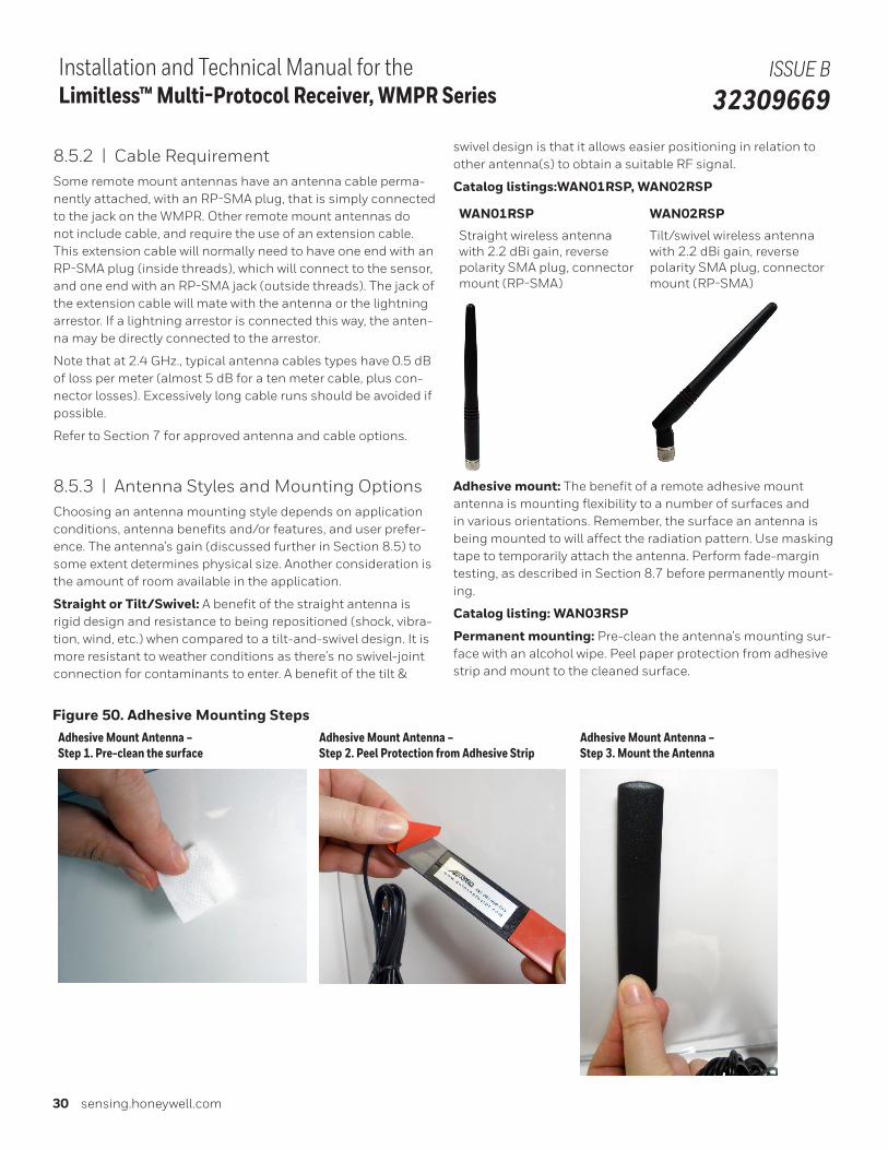
30 sensing.honeywell.com
Installation and Technical Manual for the Limitless™ Multi-Protocol Receiver, WMPR Series
ISSUE B 32309669
8.5.2 | Cable RequirementSome remote mount antennas have an antenna cable perma-nently attached, with an RP-SMA plug, that is simply connected to the jack on the WMPR. Other remote mount antennas do not include cable, and require the use of an extension cable. This extension cable will normally need to have one end with an RP-SMA plug (inside threads), which will connect to the sensor, and one end with an RP-SMA jack (outside threads). The jack of the extension cable will mate with the antenna or the lightning arrestor. If a lightning arrestor is connected this way, the anten-na may be directly connected to the arrestor.
Note that at 2.4 GHz., typical antenna cables types have 0.5 dB of loss per meter (almost 5 dB for a ten meter cable, plus con-nector losses). Excessively long cable runs should be avoided if possible.
Refer to Section 7 for approved antenna and cable options.
8.5.3 | Antenna Styles and Mounting OptionsChoosing an antenna mounting style depends on application conditions, antenna benefits and/or features, and user prefer-ence. The antenna’s gain (discussed further in Section 8.5) to some extent determines physical size. Another consideration is the amount of room available in the application.
Straight or Tilt/Swivel: A benefit of the straight antenna is rigid design and resistance to being repositioned (shock, vibra-tion, wind, etc.) when compared to a tilt-and-swivel design. It is more resistant to weather conditions as there’s no swivel-joint connection for contaminants to enter. A benefit of the tilt &
swivel design is that it allows easier positioning in relation to other antenna(s) to obtain a suitable RF signal.
Catalog listings:WAN01RSP, WAN02RSP
WAN01RSP WAN02RSP
Straight wireless antenna with 2.2 dBi gain, reverse polarity SMA plug, connector mount (RP-SMA)
Tilt/swivel wireless antenna with 2.2 dBi gain, reverse polarity SMA plug, connector mount (RP-SMA)
Adhesive mount: The benefit of a remote adhesive mount antenna is mounting flexibility to a number of surfaces and in various orientations. Remember, the surface an antenna is being mounted to will affect the radiation pattern. Use masking tape to temporarily attach the antenna. Perform fade-margin testing, as described in Section 8.7 before permanently mount-ing.
Catalog listing: WAN03RSP
Permanent mounting: Pre-clean the antenna’s mounting sur-face with an alcohol wipe. Peel paper protection from adhesive strip and mount to the cleaned surface.
Figure 50. Adhesive Mounting StepsAdhesive Mount Antenna – Step 1. Pre-clean the surface
Adhesive Mount Antenna – Step 2. Peel Protection from Adhesive Strip
Adhesive Mount Antenna – Step 3. Mount the Antenna
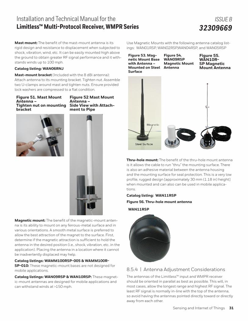
Sensing and Internet of Things 31
Installation and Technical Manual for the Limitless™ Multi-Protocol Receiver, WMPR Series
ISSUE B 32309669
Mast mount: The benefit of the mast-mount antenna is its rigid design and resistance to displacement when subjected to shock, vibration, wind, etc. It can be easily mounted high above the ground to obtain greater RF signal performance and it with-stands winds up to 100 mph.
Catalog listing: WAN06RNJ
Mast-mount bracket (Included with the 8 dBi antenna): Attach antenna to its mounting bracket. Tighten nut. Assemble two U-clamps around mast and tighten nuts. Ensure provided lock washers are compressed to a flat condition.
Figure 51. Mast Mount Antenna – Tighten nut on mounting bracket
Figure 52 Mast Mount Antenna – Side View with Attach-ment to Pipe
Magnetic mount: The benefit of the magnetic-mount anten-na is its ability to mount on any ferrous-metal surface and in various orientations. A smooth metal surface is preferred to allow the best attraction of the magnet to the surface. First, determine if the magnetic attraction is sufficient to hold the antenna in the desired position (i.e., shock, vibration, etc. in the application). Placing the antenna in a location where it cannot be inadvertently displaced may help.
Catalog listings: WAMM100RSP-005 & WAMM100R-SP-010: These magnetic-mount bases are not designed for mobile applications.
Catalog listings: WAN09RSP & WAN10RSP: These magnet-ic-mount antennas are designed for mobile applications and can withstand winds at >150 mph.
Use Magnetic Mounts with the following antenna catalog list-ings: WAN01RSP, WAN02RSP,WAN04RSP, and WAN05RSP
Figure 53. Mag-netic Mount Base with Antenna – Mounted on Steel Surface
Figure 54. WAN09RSP Magnetic Mount Antenna
Figure 55. WAN10R-SP Magnetic Mount Antenna
Thru-hole mount: The benefit of the thru-hole mount antenna is it allows the cable to run “thru” the mounting surface. There is also an adhesive material between the antenna housing and the mounting surface for seal protection. This is a very low profile, rugged design [approximately 30 mm (1.18 in) height] when mounted and can also can be used in mobile applica-tions.
Catalog listing: WAN11RSP
Figure 56. Thru-hole mount antenna
WAN11RSP
8.5.4 | Antenna Adjustment ConsiderationsThe antennas of the Limitless™ input and WMPR receiver should be oriented in parallel as best as possible. This will, in most cases, allow the longest range and highest RF signal. The least RF signal is normally in-line with the top of the antenna, so avoid having the antennas pointed directly toward or directly away from each other.
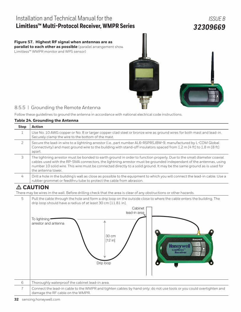
32 sensing.honeywell.com
Installation and Technical Manual for the Limitless™ Multi-Protocol Receiver, WMPR Series
ISSUE B 32309669
Figure 57. Highest RF signal when antennas are as parallel to each other as possible (parallel arrangement shown with the Limitless™ WMPR monitor and WPS sensor)
8.5.5 | Grounding the Remote AntennaFollow these guidelines to ground the antenna in accordance with national electrical code instructions.
Table 24. Grounding the AntennaStep Action
1 Use No. 10 AWG copper or No. 8 or larger copper-clad steel or bronze wire as ground wires for both mast and lead-in. Securely clamp the wire to the bottom of the mast.
2 Secure the lead-in wire to a lightning arrestor (i.e., part number AL6-RSPRSJBW-9, manufactured by L-COM Global Connectivity) and mast ground wire to the building with stand-off insulators spaced from 1,2 m [4 ft] to 1,8 m [8 ft] apart.
3 The lightning arrestor must be bonded to earth ground in order to function properly. Due to the small diameter coaxial cables used with the RP-SMA connectors, the lightning arrestor must be grounded independant of the antennas, using number 10 solid wire. This wire must be connected directly to a solid ground. It may be the same ground as is used for the antenna tower.
4 Drill a hole in the building’s wall as close as possible to the equipment to which you will connect the lead-in cable. Use a rubber grommet or feedthru tube to protect the cable from abrasion.
m CAUTIONThere may be wires in the wall. Before drilling check that the area is clear of any obstructions or other hazards.
5 Pull the cable through the hole and form a drip loop on the outside close to where the cable enters the building. The drip loop should have a radius of at least 30 cm [11.81 in].
To lightningarrestor and antenna
Drip loop
30 cm[12 in]
Cabinetlead-in area
6 Thoroughly waterproof the cabinet lead-in area.
7 Connect the lead-in cable to the WMPR and tighten cables by hand only; do not use tools or you could overtighten and damage the RF cable on the WMPR.
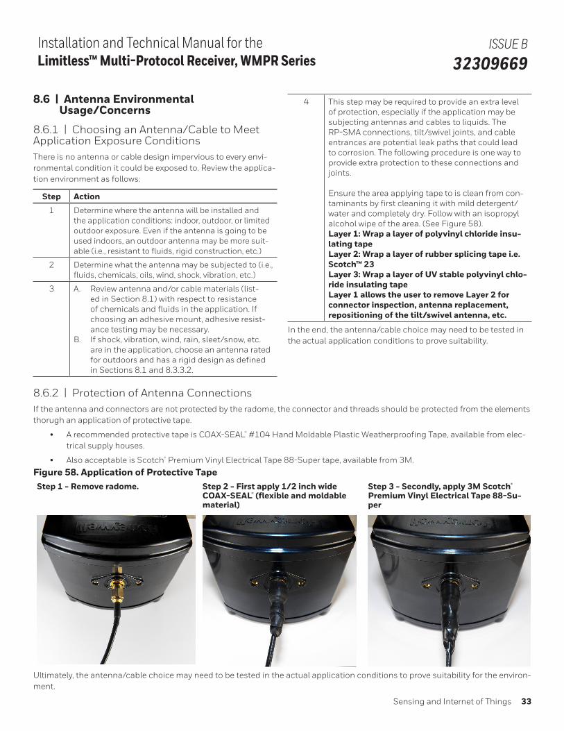
Sensing and Internet of Things 33
Installation and Technical Manual for the Limitless™ Multi-Protocol Receiver, WMPR Series
ISSUE B 32309669
8.6 | Antenna Environmental Usage/Concerns
8.6.1 | Choosing an Antenna/Cable to Meet Application Exposure ConditionsThere is no antenna or cable design impervious to every envi-ronmental condition it could be exposed to. Review the applica-tion environment as follows:
Step Action
1 Determine where the antenna will be installed and the application conditions: indoor, outdoor, or limited outdoor exposure. Even if the antenna is going to be used indoors, an outdoor antenna may be more suit-able (i.e., resistant to fluids, rigid construction, etc.)
2 Determine what the antenna may be subjected to (i.e., fluids, chemicals, oils, wind, shock, vibration, etc.)
3 A. Review antenna and/or cable materials (list-ed in Section 8.1) with respect to resistance of chemicals and fluids in the application. If choosing an adhesive mount, adhesive resist-ance testing may be necessary.
B. If shock, vibration, wind, rain, sleet/snow, etc. are in the application, choose an antenna rated for outdoors and has a rigid design as defined in Sections 8.1 and 8.3.3.2.
4 This step may be required to provide an extra level of protection, especially if the application may be subjecting antennas and cables to liquids. The RP-SMA connections, tilt/swivel joints, and cable entrances are potential leak paths that could lead to corrosion. The following procedure is one way to provide extra protection to these connections and joints.
Ensure the area applying tape to is clean from con-taminants by first cleaning it with mild detergent/water and completely dry. Follow with an isopropyl alcohol wipe of the area. (See Figure 58).Layer 1: Wrap a layer of polyvinyl chloride insu-lating tape Layer 2: Wrap a layer of rubber splicing tape i.e. Scotch™ 23Layer 3: Wrap a layer of UV stable polyvinyl chlo-ride insulating tapeLayer 1 allows the user to remove Layer 2 for connector inspection, antenna replacement, repositioning of the tilt/swivel antenna, etc.
In the end, the antenna/cable choice may need to be tested in the actual application conditions to prove suitability.
8.6.2 | Protection of Antenna ConnectionsIf the antenna and connectors are not protected by the radome, the connector and threads should be protected from the elements thorugh an application of protective tape.
• A recommended protective tape is COAX-SEAL® #104 Hand Moldable Plastic Weatherproofing Tape, available from elec-trical supply houses.
• Also acceptable is Scotch® Premium Vinyl Electrical Tape 88-Super tape, available from 3M.
Figure 58. Application of Protective TapeStep 1 - Remove radome. Step 2 - First apply 1/2 inch wide
COAX-SEAL® (flexible and moldable material)
Step 3 - Secondly, apply 3M Scotch® Premium Vinyl Electrical Tape 88-Su-per
Ultimately, the antenna/cable choice may need to be tested in the actual application conditions to prove suitability for the environ-ment.
34 sensing.honeywell.com
Installation and Technical Manual for the Limitless™ Multi-Protocol Receiver, WMPR Series
ISSUE B 32309669
8.6.3 | Outdoor Antenna Installations - Light-ning ConcernsOutdoor antenna installations can lead to the possible damage caused by nearby lightning strikes that induce charges or surg-es on the antenna and/or antenna extension cables.
A lightning arrestor such as the AL6-RSPRSJBW-9 from L-COM Global Connectivity can be reviewed against application re-quirements.
, ATTENTIONNational, local, and/or regulatory agencies may require the use of a lightning arrestor and possibly other requirements for an antenna system installation. It is recommended that the customer review and adhere to these requirements.
8.6.4 | Lightning ArrestorThe lightning arrestor may be mounted directly on the sensor, or at the far end of the antenna cable, mounted to a sheet of metal in a through-hole. Generally, the choice should be made based on having the shortest, most direct path to a good, solid ground.
If the lightning arrestor is mounted directly on the sensor, use caution when attaching a grounding wire to the arrestor to avoid putting undue stress on the sensor’s antenna connector.
If the coax cable is to enter a building, then the lightning arres-tor should be mounted as close as possible to where the lead-in wire enters the building. The lightning arrestor recommended by Honeywell (AL6-RSPRSJBW-9 from L-COM Global Connec-tivity) features a bulkhead RP-SMA connector with a rubber “O”-ring seal which can be used for mounting through an enclosure wall. Both connector ports of the lightning arrestor provide equal protection no matter which way it is installed. Either port can face the antenna and either port can face the sensor.
8.6.5 | Site Selection Before attempting to install your antenna, consider the best place to install the antenna for safety and performance.
Follow these steps to determine a safe distance from wires, power lines, and trees.
Step Action
1 Measure the height of the antenna.
2 Add this length to the length of the tower or mast and then double this total for the minimum recom-mended safe distance.
Generally speaking, the higher the antenna is above the ground, the better it performs. Good practice is to install your antenna about 1,5 m to 3 m [5 ft to 10 ft] above the roof line and away from all power lines and obstructions. If possible, find a mount-ing place directly above the wireless device so the lead-in cable can be as direct as possible.
8.6.6 | Antenna Mounting Location with Respect to Antenna Location
There are several environmental factors to consider with respect to antenna location during installation. These fac-tors can affect the radio frequency (RF) signal strength being both transmitted and received by the Limitless™ switch or sensor and the Wireless Multi-Protocol Receiver (WMPR). It is desirable for the antenna to be mounted to limit exposure of adjacent materials/objects between the Limitless™ switch or sensor and the WMPR, as they will have an effect on RF signal strength. If the mounting location for an omni-directional an-tenna is on the side of a building or tower, the antenna pattern will be degraded on the building or tower side.
Obstacles that affect antenna patterns and RF signal strength:
• Indoor: Concrete, wood, drywall, and metal walls, etc.
• Outdoor: Vehicles, buildings, trees, structures, topolo-gy, weather conditions, chain link fence, major power cables, etc.
Rain and moisture: Wireless sensors compliant with IEEE 802.15.4 operate in a 2.4 GHz band. As the peak absorption frequency of water molecules is approximately 22 GHz, the total signal attenuation due to rain, fog or moisture is negligable (less than 0.1 dB/mile for a heavy downpour).
8.7 | Choosing an Antenna Gain (dBi) with Acceptable Fade-MarginThere are several different Limitless™ Series antenna gain op-tions to choose from. This section helps determine the antenna version(s) that will provide suitable RF signal performance for specific applications.
The Limitless™ Series antenna’s actual gain is measured by how much of the input power from the WMPR’s internal radio is concentrated in a particular direction. The WMPR antenna transmits RF signals, and also receives RF signals from a Limit-less™ input. In a particular application, transmit signal strength may be better than the receive signal strength or vice versa. The intent is to choose an antenna with the optimum gain relative to application conditions for both transmitting and receiving.
Sensing and Internet of Things 35
Installation and Technical Manual for the Limitless™ Multi-Protocol Receiver, WMPR Series
ISSUE B 32309669
Fade-margin is the amount of excess power available above and beyond what is necessary to maintain a reliable RF signal between the transmitter and receiver. Normally, an acceptable threshold of excess power to ensure effective operation in a variety of environmental conditions is 10 dB. A simple way to determine if the signal strength is sufficient is to temporar-ily install a 10 dB attenuator* between the RP-SMA plug of the antenna or remote cable and WMPR’s RP-SMA jack. This should be completed in an operating application environment with good nominal environmental conditions. Starting with the antenna chosen in Section 3 & 8.3, install the attenuator and operate the system until exposure of all normal application conditions is completed while monitoring the Lost RF Signal Output. If the fade-margin is unacceptable, the lost RF sig-nal output changes state) indicating the antenna position on the Limitless™ switch and/or WMPR receiver will need to be changed and/or another antenna type should be chosen. The RF Signal indication within the Node Status menu or Node Information Menu is useful in indicating the RF Link Strength; refer to Sections 6.3 or 6.5 for more information.
Try several mounting locations and/or antennas along with retesting each with the attenuator to determine the optimal set-up that provides an acceptable fade-margin. Remove the attenuator after testing is completed.
*Suggested sources/part numbers
• 10 dB attenuator (i.e. Crystek – Part number: CAT-TEN-0100)
• RP-SMA female to SMA male connector adaptor (i.e. Con-nector City – Part number : ADP-SMAM-RPSF)
• RP-SMA male to SMA female connector adaptor (i.e. Con-nector City – Part number : ADP-RPSM-SMAF)
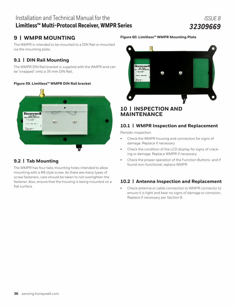
36 sensing.honeywell.com
Installation and Technical Manual for the Limitless™ Multi-Protocol Receiver, WMPR Series
ISSUE B 32309669
9 | WMPR MOUNTINGThe WMPR is intended to be mounted to a DIN Rail or mounted via the mounting plate.
9.1 | DIN Rail MountingThe WMPR DIN Rail bracket is supplied with the WMPR and can be “snapped” onto a 35 mm DIN Rail.
Figure 59. Limitless™ WMPR DIN Rail bracket
9.2 | Tab MountingThe WMPR has four tabs mounting holes intended to allow mounting with a #8 style screw. As there are many types of screw fasteners, care should be taken to not overtighten the fastener. Also, ensure that the housing is being mounted on a flat surface.
Figure 60. Limitless™ WMPR Mounting Plate
10 | INSPECTION AND MAINTENANCE
10.1 | WMPR Inspection and ReplacementPeriodic inspection
• Check the WMPR housing and connectors for signs of damage. Replace if necessary
• Check the condition of the LCD display for signs of crack-ing or damage. Replace WMPR if necessary
• Check the proper operation of the Function Buttons and if found non-functional, replace WMPR
10.2 | Antenna Inspection and Replacement• Check antenna or cable connection to WMPR connector to
ensure it is tight and bear no signs of damage or corrosion. Replace if necessary per Section 8.
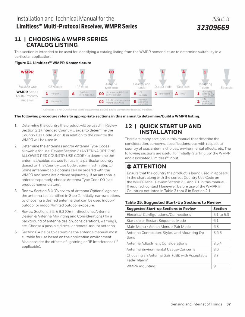
Sensing and Internet of Things 37
Installation and Technical Manual for the Limitless™ Multi-Protocol Receiver, WMPR Series
ISSUE B 32309669
11 | CHOOSING A WMPR SERIES CATALOG LISTINGThis section is intended to be used for identifying a catalog listing from the WMPR nomenclature to determine suitability in a particular application.
Figure 61. Limitless™ WMPR Nomenclature
WMPR
Receiver type
A
Country use code
A
B
US, Canada
All otherapproved countries
WMPR SeriesMulti-Protocol
Receiver
1
GEN code
A
RF code
1 Version 1 A 2.4 GHz; IEEE 802.15.4
00
02
00 No antenna; RP-SMA connector jack
2.2 dBi omni w/receiver mount; tilt/swivel
Antenna type code
1
Output code
1 EtherNet/IP™
A
Seal code
A IP20
1
Mountingcode
1
2
Mountingplate, epoxycoated CRSDINbracket, aluminum
Specials
2 Version 2*
*GEN code 2 is not ODVA certfied due to programming allowing a static (permanently assigned) IP address.
The following procedure refers to appropriate sections in this manual to determine/build a WMPR listing.
1. Determine the country the product will be used in. Review Section 2.1 (Intended Country Usage) to determine the Country Use Code (A or B) in relation to the country the WMPR will be used in.
2. Determine the antennas and/or Antenna Type Codes allowable for use. Review Section 2 (ANTENNA OPTIONS ALLOWED PER COUNTRY USE CODE) to determine the antennas/cables allowed for use in a particular country (based on the Country Use Code determined in Step 1). Some antenna/cable options can be ordered with the WMPR and some are ordered separately. If an antenna is ordered separately, choose Antenna Type Code 00 (see product nomenclature).
3. Review Section 8.4 (Overview of Antenna Options) against the antenna list identified in Step 2. Initially, narrow options by choosing a desired antenna that can be used indoor/outdoor or indoor/limited outdoor exposure.
4. Review Sections 8.2 & 8.3 (Omni-directional Antenna Design & Antenna Mounting and Considerations) for a background of antenna design, considerations, warnings, etc. Choose a possible direct- or remote-mount antenna.
5. Section 8.4 helps to determine the antenna material most suitable for use based on the application environment. Also consider the effects of lightning or RF Interference (if applicable).
12 | QUICK START UP AND INSTALLATIONThere are many sections in this manual that describe the consideration, concerns, specifications, etc. with respect to country of use, antenna choices, environmental effects, etc. The following sections are useful for initially “starting up” the WMPR and associated Limitless™ input.
, ATTENTIONEnsure that the country the product is being used in appears in the chart along with the correct Country Use Code on the WMPR label. Review Section 2.1 and 7.1 in this manual. If required, contact Honeywell before use of the WMPR in Countries not listed in Table 3 thru 6 in Section 2.1.
Table 25. Suggested Start-Up Sections to ReviewSuggested Start-up Sections to Review Section
Electrical Configurations/Connections 5.1 to 5.3
Start-up or Restart Sequence Mode 6.1
Main Menu > Action Menu > Pair Mode 6.8
Antenna Connection, Styles, and Mounting Op-tions
8.5.3
Antenna Adjustment Considerations 8.5.4
Antenna Environmental Usage/Concerns 8.6
Choosing an Antenna Gain (dBi) with Acceptable Fade-Margin
8.7
WMPR mounting 9
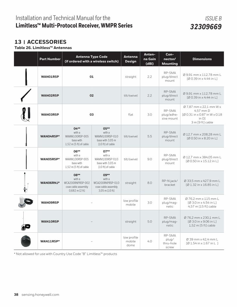
38 sensing.honeywell.com
Installation and Technical Manual for the Limitless™ Multi-Protocol Receiver, WMPR Series
ISSUE B 32309669
13 | ACCESSORIESTable 26. Limitless™ Antennas
Part NumberAntenna Type Code
(if ordered with a wireless switch)AntennaDesign
Anten-na Gain
(dBi)
Con-nector/
MountingDimensions
WAN01RSP 01 straight 2.2RP-SMA
plug/direct mount
Ø 9,91 mm x 112,78 mm L[Ø 0.39 in x 4.44 in L]
WAN02RSP 02 tilt/swivel 2.2RP-SMA
plug/direct mount
Ø 9,91 mm x 112,78 mm L[Ø 0.39 in x 4.44 in L]
WAN03RSP 03 flat 3.0RP-SMA
plug/adhe-sive mount
Ø 7,87 mm x 22,1 mm W x 4,57 mm D
[Ø 0.31 in x 0.87 in W x 0.18 in D]
3 m [9 ft] cable
WAN04RSP*
04**with a
WAMM100RSP-005 base with
1,52 m [5 ft] of cable
05**with a
WAMM100RSP-010 base with 3,05 m
[10 ft] of cable
tilt/swivel 5.5RP-SMA
plug/direct mount
Ø 12,7 mm x 208,28 mm L[Ø 0.50 in x 8.20 in L]
WAN05RSP*
06**with a
WAMM100RSP-005 base with
1,52 m [5 ft] of cable
07**with a
WAMM100RSP-010 base with 3,05 m
[10 ft] of cable
tilt/swivel 9.0RP-SMA
plug/direct mount
Ø 12,7 mm x 384,05 mm L[Ø 0.50 in x 15.12 in L]
WAN06RNJ*
08**with a
WCA200RNPRSP-002 coax cable assembly
0,682 m [2 ft]
09**with a
WCA200RNPRSP-010 coax cable assembly
3,05 m [10 ft]
straight 8.0RP-N jack/
bracketØ 33,5 mm x 427,9 mm L
[Ø 1.32 in x 16.85 in L]
WAN09RSP –low profile
mobile3.0
RP-SMA plug/mag-
netic
Ø 76,2 mm x 115 mm L[Ø 3.0 in x 4.54 in L]4,57 m [15 ft] cable
WAN10RSP – straight 5.0RP-SMA
plug/mag-netic
Ø 76,2 mm x 230,1 mm L[Ø 3.0 in x 9.06 in L]1,52 m [5 ft] cable
WAN11RSP* –low profile
mobile dome
4.0
RP-SMA plug/
thru-hole screw
Ø 39 mm x 42,4 mm L[Ø 1.54 in x 1.67 in L ]
* Not allowed for use with Country Use Code “B” Limitless™ products
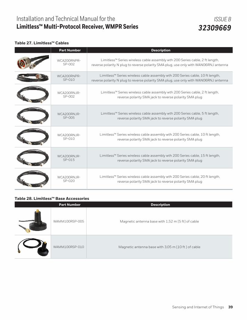
Sensing and Internet of Things 39
Installation and Technical Manual for the Limitless™ Multi-Protocol Receiver, WMPR Series
ISSUE B 32309669
Table 27. Limitless™ Cables
Part Number Description
WCA200RNPR-SP-002
Limitless™ Series wireless cable assembly wth 200 Series cable, 2 ft length, reverse polarity N plug to reverse polarity SMA plug, use only with WAN06RNJ antenna
WCA200RNPR-SP-010
Limitless™ Series wireless cable assembly wth 200 Series cable, 10 ft length, reverse polarity N plug to reverse polarity SMA plug, use only with WAN06RNJ antenna
WCA200RNJR-SP-002
Limitless™ Series wireless cable assembly wth 200 Series cable, 2 ft length, reverse polarity SMA jack to reverse polarity SMA plug
WCA200RNJR-SP-005
Limitless™ Series wireless cable assembly wth 200 Series cable, 5 ft length, reverse polarity SMA jack to reverse polarity SMA plug
WCA200RNJR-SP-010
Limitless™ Series wireless cable assembly wth 200 Series cable, 10 ft length, reverse polarity SMA jack to reverse polarity SMA plug
WCA200RNJR-SP-015
Limitless™ Series wireless cable assembly wth 200 Series cable, 15 ft length, reverse polarity SMA jack to reverse polarity SMA plug
WCA200RNJR-SP-020
Limitless™ Series wireless cable assembly wth 200 Series cable, 20 ft length, reverse polarity SMA jack to reverse polarity SMA plug
Table 28. Limitless™ Base AccessoriesPart Number Description
WAMM100RSP-005 Magnetic antenna base with 1,52 m [5 ft] of cable
WAMM100RSP-010 Magnetic antenna base with 3,05 m [10 ft ] of cable
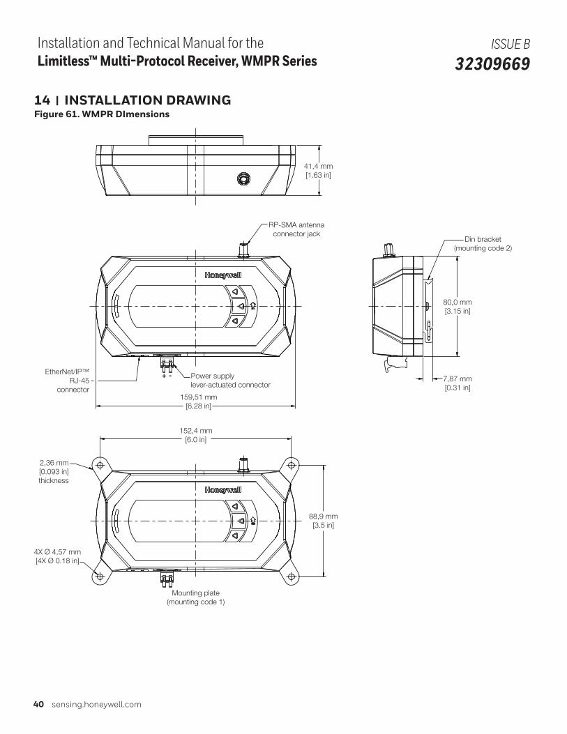
40 sensing.honeywell.com
Installation and Technical Manual for the Limitless™ Multi-Protocol Receiver, WMPR Series
ISSUE B 32309669
14 | INSTALLATION DRAWINGFigure 61. WMPR DImensions
41,4 mm[1.63 in]
RP-SMA antennaconnector jack
Din bracket(mounting code 2)
80,0 mm[3.15 in]
7,87 mm[0.31 in]
159,51 mm[6.28 in]
Power supply lever-actuated connector
EtherNet/IP™RJ-45
connector
152,4 mm[6.0 in]
Mounting plate(mounting code 1)
88,9 mm[3.5 in]
2,36 mm[0.093 in]thickness
4X Ø 4,57 mm[4X Ø 0.18 in]
+ -
Sensing and Internet of Things 41
Installation and Technical Manual for the Limitless™ Multi-Protocol Receiver, WMPR Series
ISSUE B 32309669
Licenses of Third Party Software===========================================================
This product contains software provided by third parties, which may include the below listed components. The Honeywell product that includes this file does not necessarily use all of the third party software components referred to below.
Package(s) using STMicroelectronics International license==========================================================* TIM_7PWMOutput [©Copyright 2015 STMicroelectronics International]* USART_HyperTerminal [©Copyright 2015 STMicroelectronics International]
License Text STMicroelectronics International------------------------------------------------Copyright 2015 STMicroelectronics International N.V.. All rights reserved.
Redistribution and use in source and binary forms, with or without modification, are permitted, provided that the following conditions are met:
1. Redistribution of source code must retain the above copyright notice, this list of conditions and the following disclaimer.
2. Redistributions in binary form must reproduce the above copyright notice, this list of conditions and the following disclaimer in the documentation and/or other materials provided with the distribution.
3. Neither the name of STMicroelectronics nor the names of other contributors to this software may be used to endorse or promote products derived from this software without specific written permission.
4. This software, including modifications and/or derivative works of this software, must execute solely and exclusively on microcontroller or microprocessor devices manufac-tured by or for STMicroelectronics.
5. Redistribution and use of this software other than as permitted under this license is void and will automatically terminate your rights under this license.
THIS SOFTWARE IS PROVIDED BY STMICROELECTRONICS AND CONTRIBUTORS “AS IS” AND ANY EXPRESS, IMPLIED OR STATUTORY WARRANTIES, INCLUDING, BUT NOT LIMITED TO, THE IMPLIED WARRANTIES OF MERCHANTABILITY, FITNESS FOR A PARTICULAR PURPOSE AND NON-INFRINGEMENT OF THIRD PARTY INTELLECTUAL PROPERTY RIGHTS ARE DISCLAIMED TO THE FULLEST EXTENT PERMITTED BY LAW. IN NO EVENT SHALL STMICROELECTRONICS OR CONTRIB-UTORS BE LIABLE FOR ANY DIRECT, INDIRECT, INCIDENTAL, SPECIAL, EXEMPLARY, OR CONSEQUENTIAL DAMAGES (INCLUDING, BUT NOT LIMITED TO, PROCUREMENT OF SUBSTITUTE GOODS OR SERVICES; LOSS OF USE, DATA, OR PROFITS; OR BUSINESS INTERRUPTION) HOWEVER CAUSED AND ON ANY THEORY OF LIABILITY, WHETHER IN CONTRACT, STRICT LIABILITY, OR TORT (INCLUDING NEGLIGENCE OR OTHERWISE) ARISING IN ANY WAY OUT OF THE USE OF THIS SOFTWARE, EVEN IF ADVISED OF THE POSSIBILITY OF SUCH DAMAGE.
WARRANTY/REMEDYHoneywell warrants goods of its manufacture as being free of defective materials and faulty workmanship. Honeywell’s standard product warranty applies unless agreed to otherwise by Honeywell in writing; please refer to your order acknowl-edgement or consult your local sales office for specific war-ranty details. If warranted goods are returned to Honeywell during the period of coverage, Honeywell will repair or replace, at its option, without charge those items that Honeywell, in its sole discretion, finds defective. The foregoing is buyer’s sole remedy and is in lieu of all other warranties, expressed or implied, including those of merchantability and fitness for a particular purpose. In no event shall Honeywell be liable for consequential, special, or indirect damages.
While Honeywell may provide application assistance personally, through our literature and the Honeywell web site, it is cus-tomer’s sole responsibility to determine the suitability of the product in the application.
Specifications may change without notice. The information we supply is believed to be accurate and reliable as of this printing. However, Honeywell assumes no responsibility for its use.
Installation and Technical Manual for the Limitless™ Multi-Protocol Receiver, WMPR Series
ISSUE B 32309669
Notices and TrademarksWhile this information is presented in good faith and believed to be accurate, Honeywell disclaims the implied warranties of merchantability and fitness for a particular purpose and makes no express warranties except as may be stated in its written agreement with and for its customers.
In no event is Honeywell liable to anyone for any indirect, spe-cial or consequential damages. The information and specifica-tions in this document are subject to change without notice.
Honeywell is a registered trademarks of Honeywell Internation-al Inc.
Other brand or product names are trademarks of their respec-tive owners.
COAX-SEAL® is the registered trademark of Universal Electronics.Scotch® is the registered trademark of 3M. EthernNet/IP® is the registered trademark of ODVA, Inc.
32309669-B-EN | 2 | 02/18© 2018 Honeywell International Inc. All rights reserved.
For more informationHoneywell Sensing and Internet of
Things services its customers through a
worldwide network of sales offices and
distributors. For application assistance,
current specifications, pricing or the
nearest Authorized Distributor, visit
sensing.honeywell.com or call:
Asia Pacific +65 6355-2828
Europe +44 (0) 1698 481481
USA/Canada +1-800-537-6945
Honeywell Sensing and Internet of Things9680 Old Bailes Road
Fort Mill, SC 29707
www. honeywell.com