Embed Size (px)
Citation preview
1
SMALL PACKAGED PRODUCT (2-3 TON UNITS)VERTICAL ECONOMIZER ACCESSORY
EXCLUDING 3 TON 14 SEER HP AND DUAL MODELS
Part Number:
CPECOMZR007A00
Installation Instructions Read these instructions completely before attempting to install the Vertical Economizer Accessory.
CONTENTSSAFETY CONSIDERATIONS........................................1GENERAL......................................................................1,2ACCESSORIES LIST......................................................2INSTALLATION...........................................................2-6CONFIGURATION.....................................................6-10ECONOMIZER CONTROL MODES............................6OPERATION ................................................................10SEQUENCE OF OPERATION.....................................10PERFORMANCE DATA...............................................11TROUBLESHOOTING............................................11-12WIRING DIAGRAMS .............................................13-14
SAFETY CONSIDERATIONSInstallation and servicing of air-conditioning equipment can be hazardous due to system pressure and electrical components. Only trained and qualified service personnel should install, repair, or service air-conditioning equipment.Untrained personnel can perform the basic maintenance functions of replacing filters. All other operations should be performed by trained service personnel. When working on air-conditioning equipment, observe precautions in the literature, tags, and labels attached to the unit, and other safety precautions that may apply.Recognize safety information. This is the safety-alert symbol .When you see this symbol on the unit and in instructions or manuals, be alert to the potential for personal injury. Understand these signal words; DANGER, WARNING, and CAUTION. These words are used with the safety-alert symbol. DANGER identifies the most serious hazards which will result in severe personal injury or death. WARNING signifies hazards which could result in personal injury or death. CAUTION is used to identify unsafe practices which may result in minor personal injury or product and property damage. NOTE is used to highlight suggestions which will result in enhanced installation, reliability, or operation.Follow all safety codes. Wear safety glasses, protective clothing, and work gloves. Use quenching cloth for brazing operations. Have a fire extinguisher available. Read these instructions thoroughly and follow all warnings or cautions included in literature and attached to the unit. Consult local building codes and current editions of the National Electrical Code (NEC) NFPA 70. In Canada, refer to current editions of the Canadian electrical code CSA 22.1.
GENERALEconomizers are recommended for use with only commercial packaged products that have ECM motors. The Economizer system utilizes the latest technology available for integrating the use of free cooling with mechanical cooling for rooftop units. The solid state control system optimizes energy consumption, zone comfort, and equipment cycling by operating the compressors when the outdoor-air temperature is too warm, integrating the compressor with outdoor air when free cooling is available, and locking out the compressor when outdoor-air temperature is too cold. Demand ventilation is supported.The Economizer system utilizes gear-drive technology with a direct-mount spring return actuator that will close upon loss of power. The Economizer system comes standard with an outdoor air temperature sensor, a supply air temperature sensor, and low temperature compres-sor lockout switch. Indoor enthalpy sensors, outdoor enthalpy sensors and CO2 sensors are available for field installation.Barometric relief dampers provide natural building pressurization control. Barometric relief dampers are built into the design and are standard.See Table 1 for package contents. See Table 3 for sensor usage.!
WARNINGELECTRICAL SHOCK HAZARDFailure to follow this warning could result in personal injury or death.Before installing, modifying, or servicing system, main electrical disconnect switch must be in the OFF position and install a lockout tag. There may be more than 1 disconnect switch. Lock out and tag switch with suitable warning label.
CAUTIONUNIT PERFORMANCE AND COMPONENT HAZARDFailure to follow this caution may result in unit damage.For cooling operation, the recommended airflow is 350 to 450 cfm for each 12,000 Btuh of rated cooling capacity. For heating opera-tion, the airflow must produce a temperature rise that falls within the range stamped on the unit rating plate.
!
!
PART NUMBER QTY DESCRIPTIONS
CPECOMZR007A00
1 Hood Top and Sides1 Hood Divider1 Aluminum Filter11 #10 Self-Drilling Screw and Washers4 #10x 1/2” Blunt End Screws1 #10x 1” Self-Drilling Screws1 Economizer Assembly
1 Supply Air Temperature Sensorwith Bracket
2 1” 12 x 20 Filter*1 Top Filter Rack1 Bottom Filter Rack1 Replacement Return Chamber Panel1 Compressor Cover Panel1 Extension Harness w/ Plug2 Wiring Diagram Labels
PART NUMBER 1-IN. FILTER SIZE 2-IN. FILTER SIZE
CPECOMZR007A00 2 - 12 x 20 (304.8 x 508mm) 1 - 10 x 20 (254 x 508mm)1 - 12 x 20 (304.8 x 508mm)
Table 1 - Package Contents
Table 2 - Filter Sizes
*Unscrew two brackets on the top filter rack to fit 2-in. (50.8mm) filters.
2
WARNINGELECTRICAL SHOCK HAZARDFailure to follow this warning could result in personal injury or death.Before installing or servicing system, always turn off main power to system and tag. There may be more than one disconnect switch. Turn off accessory heater power switch if applicable.
!
ACCESSORIES LISTThe economizer has several field-installed accessories available to optimize performance. Refer to Table 4 for authorized parts.
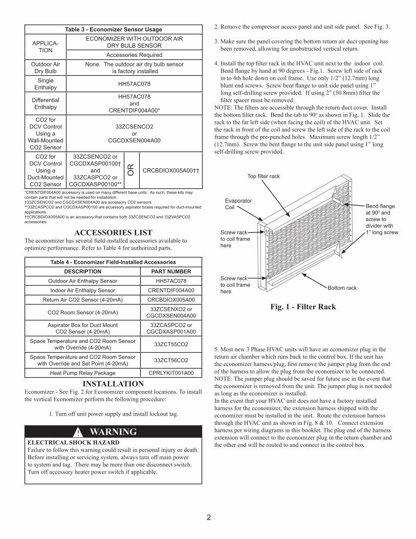
INSTALLATIONEconomizer - See Fig. 2 for Economizer component locations. To install the vertical Economizer perform the following procedure:
1. Turn off unit power supply and install lockout tag.
2. Remove the compressor access panel and unit side panel. See Fig. 3.
3. Make sure the panel covering the bottom return air duct opening has been removed, allowing for unobstructed vertical return.
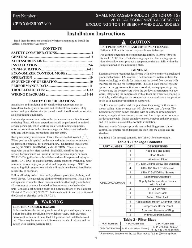
4. Install the top filter rack in the HVAC unit next to the indoor coil. Bend flange by hand at 90 degrees - Fig.1. Screw left side of rack in to 4th hole down on coil frame. Use only 1/2” (12.7mm) long blunt end screws. Screw bent flange to unit side panel using 1” long self-drilling screw provided. If using 2” (50.8mm) filter the filter spacer must be removed.NOTE: The filters are accessible through the return duct cover. Install the bottom filter rack. Bend the tab to 90o as shown in Fig. 1. Slide the rack to the far left side (when facing the coil) of the HVAC unit. Set the rack in front of the coil and screw the left side of the rack to the coil frame through the pre-punched holes. Maximum screw length 1/2” (12.7mm). Screw the bent flange to the unit side panel using 1” long self-drilling screw provided.
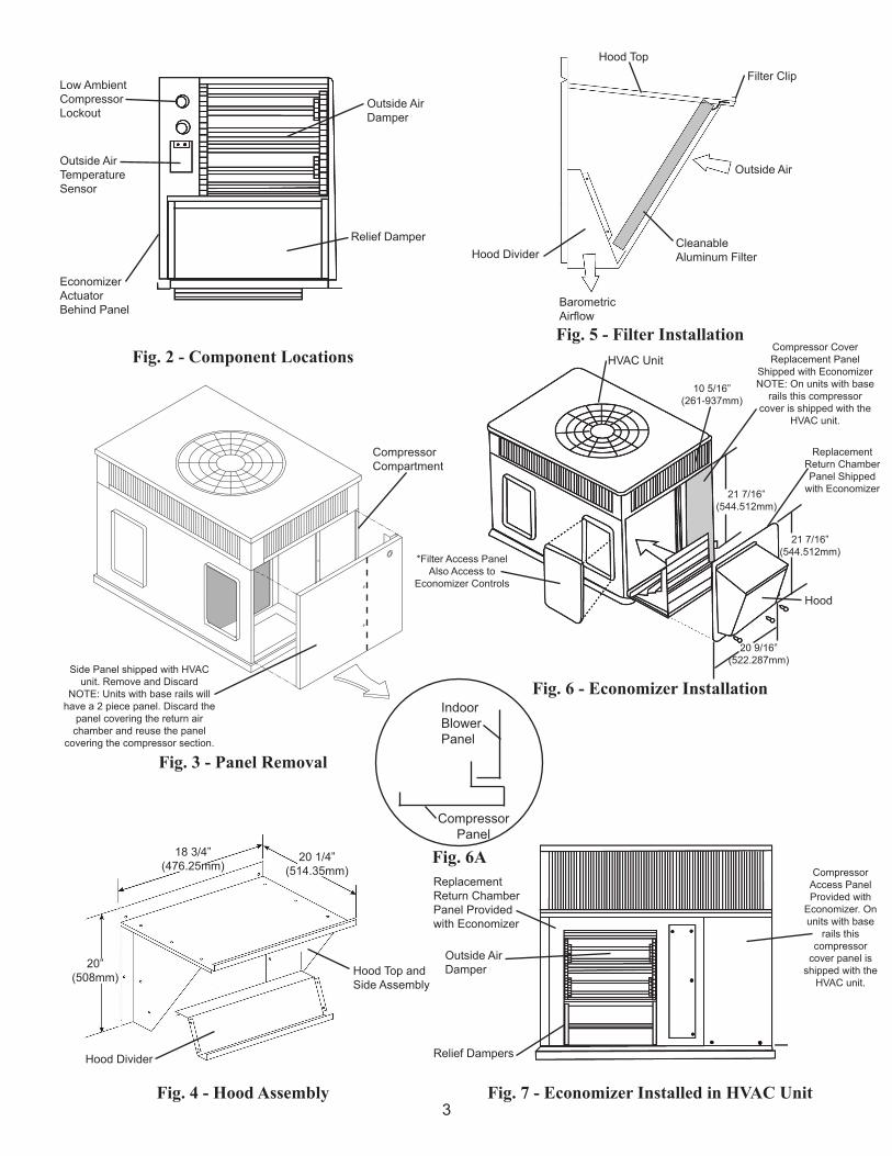
5. Most new 3 Phase HVAC units will have an economizer plug in the return air chamber which runs back to the control box. If the unit has the economizer harness/plug, first remove the jumper plug from the end of the harness to allow the plug from the economizer to be connected.NOTE: The jumper plug should be saved for future use in the event that the economizer is removed from the unit. The jumper plug is not needed as long as the economizer is installed.In the event that your HVAC unit does not have a factory installed harness for the economizer, the extension harness shipped with the economizer must be installed in the unit. Route the extension harness through the HVAC unit as shown in Fig. 8 & 10. Connect extension harness per wiring diagrams in this booklet. The plug end of the harness extension will connect to the economizer plug in the return chamber and the other end will be routed to and connect in the control box.
Table 3 - Economizer Sensor Usage
APPLICA-TION
ECONOMIZER WITH OUTDOOR AIRDRY BULB SENSORAccessories Required
Outdoor AirDry Bulb
None. The outdoor air dry bulb sensor is factory installed
SingleEnthalpy HH57AC078
DifferentialEnthalpy
HH57AC078and
CRENTDIF004A00*CO2 for
DCV ControlUsing a
Wall-MountedCO2 Sensor
33ZCSENCO2or
CGCDXSEN004A00
CO2 for DCV Control
Using a Duct-MountedCO2 Sensor
33ZCSENCO2 orCGCDXASP00100†
and33ZCASPCO2 or
CGCDXASP00100**
CRCBDIOX005A00††OR
*CRENTDIF004A00 accessory is used on many different base units. As such, these kits may contain parts that will not be needed for installation.†33ZCSENCO2 and CGCDXSEN004A00 are accessory CO2 sensors.**33ZCASPCO2 and CGCDXASP00100 are accessory aspirator boxes required for duct-mounted applications.††CRCBDIOX005A00 is an accessory that contains both 33ZCSENCO2 and 33ZVASPCO2 accessories.
Table 4 - Economizer Field-Installed AccessoriesDESCRIPTION PART NUMBER
Outdoor Air Enthalpy Sensor HH57AC078
Indoor Air Enthalpy Sensor CRENTDIF004A00
Return Air CO2 Sensor (4-20mA) CRCBDIOX005A00
CO2 Room Sensor (4-20mA) 33ZCSENXO2 orCGCDXSEN004A00
Aspirator Box for Duct MountCO2 Sensor (4-20mA)
33ZCASPCO2 orCGCDXASP001A00
Space Temperature and CO2 Room Sensorwith Override (4-20mA) 33ZCT55CO2
Space Temperature and CO2 Room Sensorwith Override and Set Point (4-20mA) 33ZCT56CO2
Heat Pump Relay Package CPRLYKIT001A00
Fig. 1 - Filter Rack
Top filter rack
Bottom rack
EvaporatorCoil
Screw rackto coil framehere
Screw rackto coil framehere
Bend flangeat 900 andscrew to divider with1” long screw
3
IndoorBlowerPanel
CompressorPanel
Fig. 2 - Component LocationsFig. 5 - Filter Installation
Fig. 3 - Panel Removal
Fig. 6 - Economizer Installation
Fig. 4 - Hood Assembly Fig. 7 - Economizer Installed in HVAC Unit
Fig. 6A
Low AmbientCompressorLockout
Outside AirTemperatureSensor
EconomizerActuatorBehind Panel
Relief Damper
Hood TopFilter Clip
Outside Air
CleanableAluminum Filter
BarometricAirflow
Side Panel shipped with HVACunit. Remove and Discard
NOTE: Units with base rails willhave a 2 piece panel. Discard the
panel covering the return air chamber and reuse the panel
covering the compressor section.
Compressor CoverReplacement Panel
Shipped with EconomizerNOTE: On units with base
rails this compressorcover is shipped with the
HVAC unit.
CompressorCompartment
10 5/16”(261-937mm)
HVAC Unit
*Filter Access PanelAlso Access to
Economizer Controls
21 7/16”(544.512mm)
ReplacementReturn ChamberPanel Shipped
with Economizer
21 7/16”(544.512mm)
Hood
20 9/16”(522.287mm)
Hood Divider
Outside Air Damper
18 3/4”(476.25mm)
20 1/4”(514.35mm)
20”(508mm)
Hood Divider
Hood Top andSide Assembly
ReplacementReturn ChamberPanel Providedwith Economizer
Outside AirDamper
Relief Dampers
CompressorAccess PanelProvided with
Economizer. On units with base
rails thiscompressor
cover panel is shipped with the
HVAC unit.
4
IndoorBlower
Supply Air TemperatureSensor (SAT)
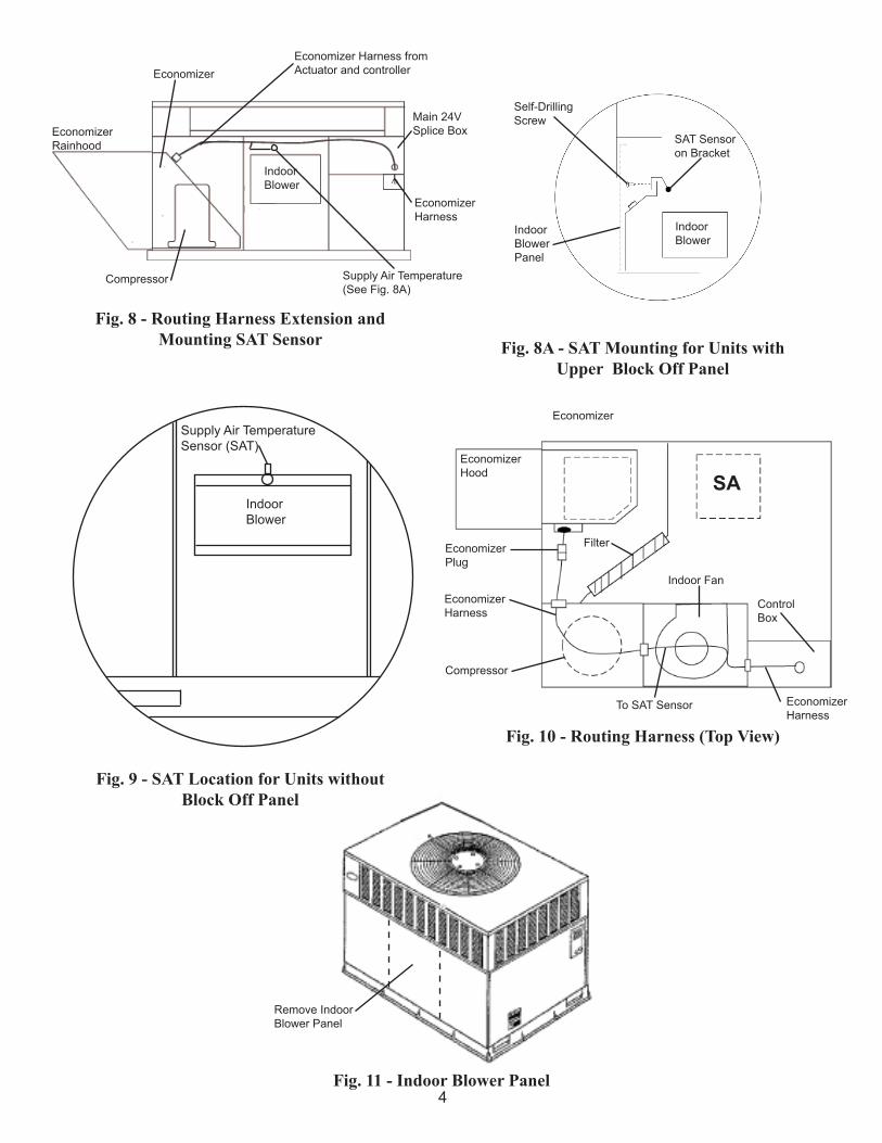
Fig. 8 - Routing Harness Extension andMounting SAT Sensor Fig. 8A - SAT Mounting for Units with
Upper Block Off Panel
Fig. 9 - SAT Location for Units without Block Off Panel
Fig. 10 - Routing Harness (Top View)
Fig. 11 - Indoor Blower Panel
EconomizerRainhood
EconomizerHood
Economizer
EconomizerPlug
EconomizerHarness
Compressor
To SAT Sensor EconomizerHarness
Control Box
Indoor Fan
Filter
SA
EconomizerEconomizer Harness fromActuator and controller
Main 24VSplice Box
Self-DrillingScrew
IndoorBlowerPanel
SAT Sensoron Bracket
IndoorBlower
EconomizerHarness
Supply Air Temperature(See Fig. 8A)
Compressor
IndoorBlower
Remove IndoorBlower Panel
5
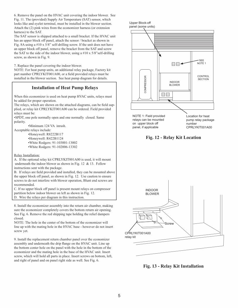
Fig. 12 - Relay Kit Location
Fig. 13 - Relay Kit Installation
6. Remove the panel on the HVAC unit covering the indoor blower. See Fig. 11. The (provided) Supply Air Temperature (SAT) sensor, which looks like and eyelet terminal, must be installed in the blower section. Attach the (2) pink wires from the economizer harness (or extension harness) to the SAT.The SAT sensor is shipped attached to a small bracket. If the HVAC unit has an upper block off panel, attach the sensor / bracket as shown in Fig. 8A using a #10 x 5/8” self-drilling screw. If the unit does not have an upper block off panel, remove the bracket from the SAT and screw the SAT to the side of the indoor blower, using a #10 x 5/8”self-drilling screw, as shown in Fig. 9.
7. Replace the panel covering the indoor blower.NOTE: For heat pump units, an additional relay package, Factory kit part number CPRLYKIT001A00, or a field provided relays must be installed in the blower section. See heat pump diagram for details.
Installation of Heat Pump Relays
When this economizer is used on heat pump HVAC units, relays must be added for proper operation.The relays, which are shown on the attached diagrams, can be field sup-plied, or relay kit CPRLYKIT001A00 can be ordered. Field provided relays must be:•SPDT, one pole normally open and one normally closed. Same polarity. •Minimum 124 VA inrush.Acceptable relays include: •Honeywell: R8222B117 •Honeywell: R422B1124 •White Rodgers: 91-103001-13002 •White Rodgers: 91-102006-13302
Relay Installation:A. If the optional relay kit CPRLYKIT001A00 is used, it will mount underneath the indoor blower as shown in Fig. 12 & 13. Follow instructions sent with the package.B. If relays are field provided and installed, they can be mounted above the upper block off panel, as shown in Fig. 12. Use caution to ensure screws to do not interfere with blower operation, Blunt end screws are recommended.C. If no upper block off panel is present mount relays on compressor partition below indoor blower on left as shown in Fig. 12.D. Wire the relays per diagram in this instruction.
8. Install the economizer assembly into the return air chamber, making sure the economizer completely covers the bottom return air opening. See Fig. 6. Remove the red shipping tape holding the relief dampers closed.NOTE: The hole in the center of the bottom of the economizer will line up with the mating hole in the HVAC base - however do not insert screw yet.
9. Install the replacement return chamber panel over the economizer assembly and underneath the drip flange on the HVAC unit. Line up the bottom center hole on the panel with the hole in the bottom of the economizer and the mating hole in the base of the HVAC unit. Insert screw, which will hold all parts in place. Insert screws on bottom, left, and right of panel and on panel right side as well. See Fig. 6.
Screw
INDOORBLOWER
CPRLYKIT001A00relay kit
NOTE 1: Field providedrelays can be mounted on upper block off panel, if applicable
Location for heatpump relay packagenumberCPRLYKIT001A00
CONTROLSECTION
INDOORBLOWER
SEENOTE 1
CO
MP
RE
SS
OR
Upper Block-offpanel (some units)
6
10. Remove the hood parts from the economizer package. Assemble as shown in Fig. 4 by screwing together with provided #10 x 5/8” screws.
11. Caulk or gasket the back side of the hood mating flanges. Install assembled hood over the economizer opening in the replacement return chamber panel. Screw in place through pre-punched holes. Make sure all seams are watertight.
12. Open the filter clips on the inside of the hood top. Insert the aluminum filter into the hood and close the clips to hold in place. See Fig. 5.
13. Remove the filter access panel (horizontal return panel) and install disposable filters in filter rack behind filter clips. Fig. 1. See Table 2 for filter sizes.NOTE: The economizer control settings and the filters are accessible through the horizontal return opening on side of HVAC unit. See Fig. 6.
14. Through the filter access door (horizontal return panel), adjust the settings on the economizer controller. Review the settings in the Operation section: 1. The standard economizer controller has a factory setting of 63o F (17o C) for the outdoor air temperature changeover and 55o F (13o C) for the supply air (mixed air) temperature sensor. The outdoor air temperature changeover setting is adjusted on the sensor by setting the dip switches on the sensor. The ABCD potentiometer on the economizer controller should be set to the “D” position. 2. The low ambient compressor lockout switch setting is fixed at 42o F (6o C). 3. The minimum position for the outdoor air damper can be configured at the controller. When not using a CO2 sensor, the DCV Max potentiometer must be completely closed (CCW) for the Minimum Position potentiometer to function correctly. 4. Settings for the optional outdoor enthalpy sensor, indoor enthalpy sensor, and CO2 sensor can also be configured at the controller.
15. Replace the filter access panel. Screw in place.
16. Install the compressor access panel provided with the economizer. Secure to HVAC unit per Figs. 6 and 7. Units with base rails will have compressor panel shipped with.
17. Install all economizer accessories then power HVAC unit and test cycle economizer.
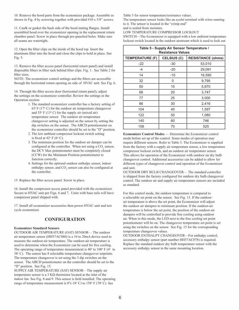
CONFIGURATION Economizer Standard SensorsOUTDOOR AIR TEMPERATURE (OAT) SENSOR— The outdoor air temperature sensor (HH57AC080) is a 10 to 20mA device used to measure the outdoor-air temperature. The outdoor-air temperature is used to determine when the Economizer can be used for free cooling. The operating range of temperature measurement is 40o to 100o F (4o to 38o C). The sensor has 8 selectable temperature changeover setpoints. The temperature changeover is set using the 3 dip switches on the sensor. The ABCD potentiometer on the controller should be set to the “D” position. See Fig. 15.SUPPLY AIR TEMPERATURE (SAT) SENSOR—The supply air temperature sensor is a 3 KΩ thermistor located at the inlet of the indoor fan. See Fig. 8 and 9. This sensor is field installed. The operating range of temperature measurement is 0°(-18o C) to 158o F (70o C). See
Economizer Control Modes — Determine the Economizer control mode before set up of the control. Some modes of operation may require different sensors. Refer to Table 3. The Economizer is supplied from the factory with a supply air temperature sensor, a low temperature compressor lockout switch, and an outdoor air temperature sensor. This allows for operation of the Economizer with outdoor air dry bulb changeover control. Additional accessories can be added to allow for different types of changeover control and operation of the Economizer and unit.OUTDOOR DRY BULB CHANGEOVER— The standard controller is shipped from the factory configured for outdoor dry bulb changeover control. The outdoor air and supply air temperature sensors are included as standard.
For this control mode, the outdoor temperature is compared to a selectable set point on the sensor. See Fig. 15. If the outdoor-air temperature is above the set point, the Economizer will adjust the outdoor air dampers to minimum position. If the outdoor-air temperature is below the set point, the position of the outdoor-air dampers will be controlled to provide free cooling using outdoor air. When in this mode, the LED next to the free cooling set point potentiometer will be on. The changeover temperature set point is set using the switches on the sensor. See Fig. 15 for the corresponding temperature changeover values.OUTDOOR ENTHALPY CHANGEOVER—For enthalpy control, accessory enthalpy sensor (part number HH57AC078) is required. Replace the standard outdoor dry bulb temperature sensor with the accessory enthalpy sensor in the same mounting location.
Table 5 - Supply Air Sensor Temperature /Resistance Values
TEMPERATURE (F) CELSIUS (C) RESISTANCE (ohms)-22 -30 53,010-4 -20 29,09114 -10 16,59032 0 9,79550 10 5,97068 20 3,74777 25 3,00086 30 2,416
104 40 1,597122 50 1,080140 60 746158 70 525
Table 5 for sensor temperature/resistance values.The temperature sensor looks like an eyelet terminal with wires running to it. The sensor is located in the “crimp end”and is sealed from moisture.LOW TEMPERATURE COMPRESSOR LOCKOUTSWITCH—The Economizer is equipped with a low ambient temperature lockout switch located in the outdoor airstream which is used to lock out
7
1
Selectable Temperature Options
N1
N
P1
T1
AQ1
SO+
SR+
SR
SO
AQ
T
P
2V 10VSet
EXH
EXH
MinPos
Open
2V 10VMax
DCV
DCV
FREECOOL
DCV
Set10V2V
B
A D
C
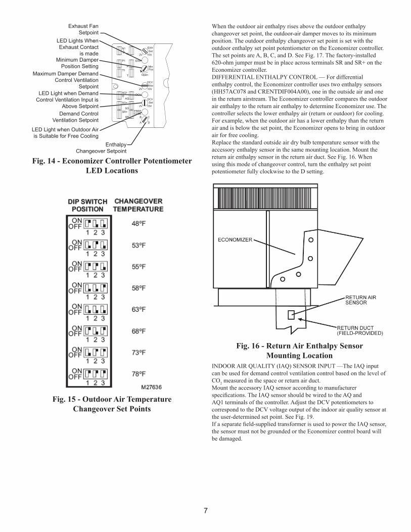
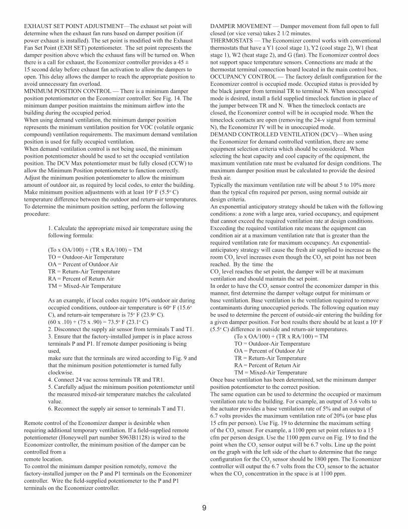
Fig. 14 - Economizer Controller PotentiometerLED Locations
Exhaust FanSetpoint
LED Lights WhenExhaust Contact
is madeMinimum Damper
Position SettingMaximum Damper Demand
Control VentilationSetpoint
LED Light when Demand Control Ventilation Input is
Above SetpointDemand Control
Ventilation Setpoint
LED Light when Outdoor Air is Suitable for Free Cooling
EnthalpyChangeover Setpoint
Fig. 15 - Outdoor Air TemperatureChangeover Set Points
Fig. 16 - Return Air Enthalpy Sensor Mounting Location
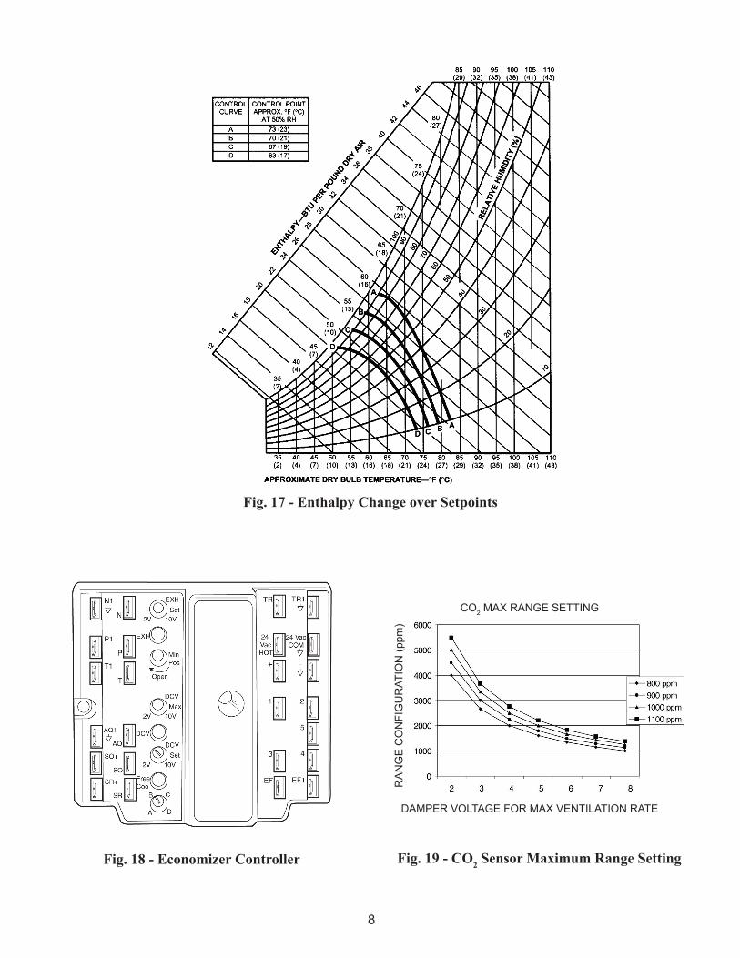
When the outdoor air enthalpy rises above the outdoor enthalpy changeover set point, the outdoor-air damper moves to its minimum position. The outdoor enthalpy changeover set point is set with the outdoor enthalpy set point potentiometer on the Economizer controller. The set points are A, B, C, and D. See Fig. 17. The factory-installed 620-ohm jumper must be in place across terminals SR and SR+ on the Economizer controller. DIFFERENTIAL ENTHALPY CONTROL — For differential enthalpy control, the Economizer controller uses two enthalpy sensors (HH57AC078 and CRENTDIF004A00), one in the outside air and one in the return airstream. The Economizer controller compares the outdoor air enthalpy to the return air enthalpy to determine Economizer use. The controller selects the lower enthalpy air (return or outdoor) for cooling. For example, when the outdoor air has a lower enthalpy than the return air and is below the set point, the Economizer opens to bring in outdoor air for free cooling.Replace the standard outside air dry bulb temperature sensor with the accessory enthalpy sensor in the same mounting location. Mount the return air enthalpy sensor in the return air duct. See Fig. 16. When using this mode of changeover control, turn the enthalpy set point potentiometer fully clockwise to the D setting.
INDOOR AIR QUALITY (IAQ) SENSOR INPUT —The IAQ input can be used for demand control ventilation control based on the level of CO2 measured in the space or return air duct.Mount the accessory IAQ sensor according to manufacturer specifications. The IAQ sensor should be wired to the AQ and AQ1 terminals of the controller. Adjust the DCV potentiometers to correspond to the DCV voltage output of the indoor air quality sensor at the user-determined set point. See Fig. 19.If a separate field-supplied transformer is used to power the IAQ sensor, the sensor must not be grounded or the Economizer control board will be damaged.
8
Fig. 17 - Enthalpy Change over Setpoints
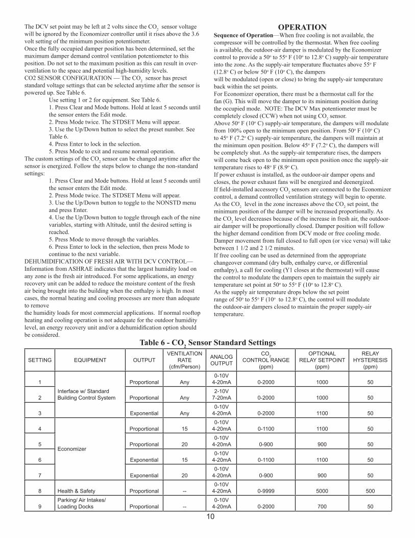
Fig. 19 - CO2 Sensor Maximum Range SettingFig. 18 - Economizer Controller
CO2 MAX RANGE SETTING
DAMPER VOLTAGE FOR MAX VENTILATION RATE
RA
NG
E C
ON
FIG
UR
ATIO
N (p
pm)
9
EXHAUST SET POINT ADJUSTMENT—The exhaust set point will determine when the exhaust fan runs based on damper position (if power exhaust is installed). The set point is modified with the Exhaust Fan Set Point (EXH SET) potentiometer. The set point represents the damper position above which the exhaust fans will be turned on. When there is a call for exhaust, the Economizer controller provides a 45 ± 15 second delay before exhaust fan activation to allow the dampers to open. This delay allows the damper to reach the appropriate position to avoid unnecessary fan overload.MINIMUM POSITION CONTROL — There is a minimum damper position potentiometer on the Economizer controller. See Fig. 14. The minimum damper position maintains the minimum airflow into the building during the occupied period.When using demand ventilation, the minimum damper position represents the minimum ventilation position for VOC (volatile organic compound) ventilation requirements. The maximum demand ventilation position is used for fully occupied ventilation.When demand ventilation control is not being used, the minimum position potentiometer should be used to set the occupied ventilation position. The DCV Max potentiometer must be fully closed (CCW) to allow the Minimum Position potentiometer to function correctly.Adjust the minimum position potentiometer to allow the minimum amount of outdoor air, as required by local codes, to enter the building. Make minimum position adjustments with at least 10o F (5.5o C) temperature difference between the outdoor and return-air temperatures.To determine the minimum position setting, perform the following procedure:
1. Calculate the appropriate mixed air temperature using the following formula:
(To x OA/100) + (TR x RA/100) = TM TO = Outdoor-Air Temperature OA = Percent of Outdoor Air TR = Return-Air Temperature RA = Percent of Return Air TM = Mixed-Air Temperature
As an example, if local codes require 10% outdoor air during occupied conditions, outdoor-air temperature is 60o F (15.6o C), and return-air temperature is 75o F (23.9o C). (60 x .10) + (75 x .90) = 73.5o F (23.1o C) 2. Disconnect the supply air sensor from terminals T and T1. 3. Ensure that the factory-installed jumper is in place across terminals P and P1. If remote damper positioning is being used, make sure that the terminals are wired according to Fig. 9 and that the minimum position potentiometer is turned fully clockwise. 4. Connect 24 vac across terminals TR and TR1. 5. Carefully adjust the minimum position potentiometer until the measured mixed-air temperature matches the calculated value. 6. Reconnect the supply air sensor to terminals T and T1.
Remote control of the Economizer damper is desirable when requiring additional temporary ventilation. If a field-supplied remote potentiometer (Honeywell part number S963B1128) is wired to the Economizer controller, the minimum position of the damper can be controlled from aremote location.To control the minimum damper position remotely, remove the factory-installed jumper on the P and P1 terminals on the Economizer controller. Wire the field-supplied potentiometer to the P and P1 terminals on the Economizer controller.
DAMPER MOVEMENT — Damper movement from full open to full closed (or vice versa) takes 2 1/2 minutes.THERMOSTATS — The Economizer control works with conventional thermostats that have a Y1 (cool stage 1), Y2 (cool stage 2), W1 (heat stage 1), W2 (heat stage 2), and G (fan). The Economizer control does not support space temperature sensors. Connections are made at the thermostat terminal connection board located in the main control box.OCCUPANCY CONTROL — The factory default configuration for the Economizer control is occupied mode. Occupied status is provided by the black jumper from terminal TR to terminal N. When unoccupied mode is desired, install a field supplied timeclock function in place of the jumper between TR and N. When the timeclock contacts areclosed, the Economizer control will be in occupied mode. When the timeclock contacts are open (removing the 24-v signal from terminal N), the Economizer IV will be in unoccupied mode.DEMAND CONTROLLED VENTILATION (DCV)—When using the Economizer for demand controlled ventilation, there are some equipment selection criteria which should be considered. When selecting the heat capacity and cool capacity of the equipment, the maximum ventilation rate must be evaluated for design conditions. The maximum damper position must be calculated to provide the desired fresh air.Typically the maximum ventilation rate will be about 5 to 10% more than the typical cfm required per person, using normal outside air design criteria.An exponential anticipatory strategy should be taken with the following conditions: a zone with a large area, varied occupancy, and equipment that cannot exceed the required ventilation rate at design conditions. Exceeding the required ventilation rate means the equipment can condition air at a maximum ventilation rate that is greater than the required ventilation rate for maximum occupancy. An exponential-anticipatory strategy will cause the fresh air supplied to increase as the room CO2 level increases even though the CO2 set point has not been reached. By the time the CO2 level reaches the set point, the damper will be at maximum ventilation and should maintain the set point.In order to have the CO2 sensor control the economizer damper in this manner, first determine the damper voltage output for minimum or base ventilation. Base ventilation is the ventilation required to remove contaminants during unoccupied periods. The following equation may be used to determine the percent of outside-air entering the building for a given damper position. For best results there should be at least a 10o F (5.5o C) difference in outside and return-air temperatures. (To x OA/100) + (TR x RA/100) = TM TO = Outdoor-Air Temperature OA = Percent of Outdoor Air TR = Return-Air Temperature RA = Percent of Return Air TM = Mixed-Air TemperatureOnce base ventilation has been determined, set the minimum damper position potentiometer to the correct position.The same equation can be used to determine the occupied or maximum ventilation rate to the building. For example, an output of 3.6 volts to the actuator provides a base ventilation rate of 5% and an output of 6.7 volts provides the maximum ventilation rate of 20% (or base plus 15 cfm per person). Use Fig. 19 to determine the maximum setting of the CO2 sensor. For example, a 1100 ppm set point relates to a 15 cfm per person design. Use the 1100 ppm curve on Fig. 19 to find the point when the CO2 sensor output will be 6.7 volts. Line up the point on the graph with the left side of the chart to determine that the range configuration for the CO2 sensor should be 1800 ppm. The Economizer controller will output the 6.7 volts from the CO2 sensor to the actuator when the CO2 concentration in the space is at 1100 ppm.
10
The DCV set point may be left at 2 volts since the CO2 sensor voltage will be ignored by the Economizer controller until it rises above the 3.6 volt setting of the minimum position potentiometer.Once the fully occupied damper position has been determined, set the maximum damper demand control ventilation potentiometer to this position. Do not set to the maximum position as this can result in over-ventilation to the space and potential high-humidity levels.CO2 SENSOR CONFIGURATION — The CO2 sensor has preset standard voltage settings that can be selected anytime after the sensor is powered up. See Table 6. Use setting 1 or 2 for equipment. See Table 6. 1. Press Clear and Mode buttons. Hold at least 5 seconds until the sensor enters the Edit mode. 2. Press Mode twice. The STDSET Menu will appear. 3. Use the Up/Down button to select the preset number. See Table 6. 4. Press Enter to lock in the selection. 5. Press Mode to exit and resume normal operation.The custom settings of the CO2 sensor can be changed anytime after the sensor is energized. Follow the steps below to change the non-standard settings: 1. Press Clear and Mode buttons. Hold at least 5 seconds until the sensor enters the Edit mode. 2. Press Mode twice. The STDSET Menu will appear. 3. Use the Up/Down button to toggle to the NONSTD menu and press Enter. 4. Use the Up/Down button to toggle through each of the nine variables, starting with Altitude, until the desired setting is reached. 5. Press Mode to move through the variables. 6. Press Enter to lock in the selection, then press Mode to continue to the next variable.DEHUMIDIFICATION OF FRESH AIR WITH DCV CONTROL—Information from ASHRAE indicates that the largest humidity load on any zone is the fresh air introduced. For some applications, an energy recovery unit can be added to reduce the moisture content of the fresh air being brought into the building when the enthalpy is high. In most cases, the normal heating and cooling processes are more than adequate to removethe humidity loads for most commercial applications. If normal rooftop heating and cooling operation is not adequate for the outdoor humidity level, an energy recovery unit and/or a dehumidification option should be considered.
OPERATIONSequence of Operation—When free cooling is not available, the compressor will be controlled by the thermostat. When free cooling is available, the outdoor-air damper is modulated by the Economizer control to provide a 50o to 55o F (10o to 12.8o C) supply-air temperature into the zone. As the supply-air temperature fluctuates above 55o F(12.8o C) or below 50o F (10o C), the damperswill be modulated (open or close) to bring the supply-air temperature back within the set points.For Economizer operation, there must be a thermostat call for the fan (G). This will move the damper to its minimum position during the occupied mode. NOTE: The DCV Max potentiometer must be completely closed (CCW) when not using CO2 sensor.Above 50o F (10o C) supply-air temperature, the dampers will modulate from 100% open to the minimum open position. From 50o F (10o C) to 45o F (7.2o C) supply-air temperature, the dampers will maintain at the minimum open position. Below 45o F (7.2o C), the dampers will be completely shut. As the supply-air temperature rises, the dampers will come back open to the minimum open position once the supply-air temperature rises to 48o F (8.9o C).If power exhaust is installed, as the outdoor-air damper opens and closes, the power exhaust fans will be energized and deenergized.If field-installed accessory CO2 sensors are connected to the Economizer control, a demand controlled ventilation strategy will begin to operate. As the CO2 level in the zone increases above the CO2 set point, the minimum position of the damper will be increased proportionally. As the CO2 level decreases because of the increase in fresh air, the outdoor-air damper will be proportionally closed. Damper position will follow the higher demand condition from DCV mode or free cooling mode.Damper movement from full closed to full open (or vice versa) will take between 1 1/2 and 2 1/2 minutes.If free cooling can be used as determined from the appropriate changeover command (dry bulb, enthalpy curve, or differential enthalpy), a call for cooling (Y1 closes at the thermostat) will cause the control to modulate the dampers open to maintain the supply air temperature set point at 50o to 55o F (10o to 12.8o C).As the supply air temperature drops below the set pointrange of 50o to 55o F (10o to 12.8o C), the control will modulate the outdoor-air dampers closed to maintain the proper supply-air temperature.
Table 6 - CO2 Sensor Standard Settings
SETTING EQUIPMENT OUTPUTVENTILATION
RATE(cfm/Person)
ANALOGOUTPUT
CO2CONTROL RANGE
(ppm)
OPTIONALRELAY SETPOINT
(ppm)
RELAYHYSTERESIS
(ppm)
1Interface w/ StandardBuilding Control System
Proportional Any0-10V
4-20mA 0-2000 1000 50
2 Proportional Any2-10V
7-20mA 0-2000 1000 50
3 Exponential Any0-10V
4-20mA 0-2000 1100 50
4
Economizer
Proportional 150-10V
4-20mA 0-1100 1100 50
5 Proportional 200-10V
4-20mA 0-900 900 50
6 Exponential 150-10V
4-20mA 0-1100 1100 50
7 Exponential 200-10V
4-20mA 0-900 900 50
8 Health & Safety Proportional --0-10V
4-20mA 0-9999 5000 500
9Parking/ Air Intakes/Loading Docks Proportional --
0-10V4-20mA 0-2000 700 50
11
TROUBLESHOOTINGSee Table 8 for Economizer logic.An Economizer simulator program is available to help with Economizer training and troubleshooting.Economizer Preparation —This procedure is used to prepare the Economizer for troubleshooting. No troubleshooting or testing is done by performing the following procedure.NOTE: This procedure requires a 9-v battery, 1.2 kilo-ohm resistor, and a 5.6 kilo-ohm resistor which are not supplied with the Economizer. 1. Disconnect power at TR and TR1. All LEDs should be off. Exhaust fan contacts should be open. 2. Disconnect device at P and P1. 3. Jumper P to P1. 4. Disconnect wires at T and T1. Place 5.6 kilo-ohm resistor across T and T1. 5. Jumper TR to 1. 6. Jumper TR to N. 7. If connected, remove sensor from terminals SO and +. Connect 1.2 kilo-ohm 4074EJM checkout resistor across terminals SO and +. 8. Put 620-ohm resistor across terminals SR and +. 9. Set minimum position, DCV set point, and exhaust potentiometers fully CCW (counterclockwise). 10. Set DCV maximum position potentiometer fully CW (clockwise). 11. Set enthalpy potentiometer to D. 12. Apply power (24 vac) to terminals TR and TR1.Differential Enthalpy — To check differential enthalpy: 1. Make sure Economizer preparation procedure has been performed. 2. Place 620-ohm resistor across SO and +. 3. Place 1.2 kilo-ohm resistor across SR and +. The Free Cool LED should be lit. 4. Remove 620-ohm resistor across SO and +. The Free Cool LED should turn off. 5. Return Economizer settings and wiring to normal after completing troubleshooting.Single Enthalpy—To check single enthalpy: 1. Make sure Economizer preparation procedure has been performed. 2. Set the enthalpy potentiometer to A (fully CCW). The Free Cool LED should be lit. 3. Set the enthalpy potentiometer to D (fully CW). The Free Cool LED should turn off.
4. Return Economizer settings and wiring to normal after completing troubleshooting.DCV (Demand Controlled Ventilation) and Power Exhaust— To check DCV and Power Exhaust: 1. Make sure Economizer preparation procedure has been performed. 2. Ensure terminals AQ and AQ1 are open. The LED for both DCV and Exhaust should be off. The actuator should be fully closed. 3. Connect a 9-v battery to AQ (positive node) and AQ1 (negative node). The LED for both DCV and Exhaust should turn on. The actuator should drive to between 90 and 95% open. 4. Turn the Exhaust potentiometer CW until the Exhaust LED turns off. The LED should turn off when the potentiometer is approximately 90%. The actuator should remain in position. 5. Turn the DCV set point potentiometer CW until the DCV LED turns off. The DCV LED should turn off when the potentiometer is approximately 9-v. The actuator should drive fully closed. 6. Turn the DCV and Exhaust potentiometers CCW until the Exhaust LED turns on. The exhaust contacts will close 30 to 120 seconds after the Exhaust LED turns on. 7. Return Economizer IV settings and wiring to normal after completing troubleshooting.
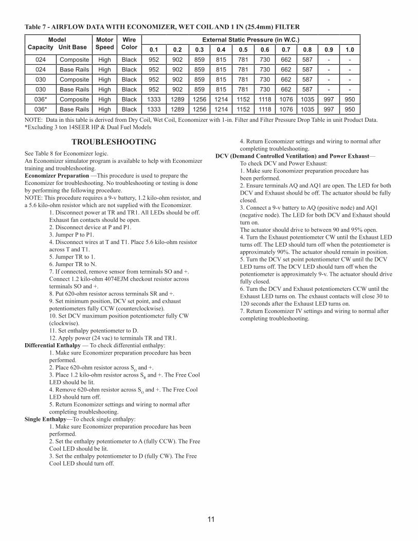
ModelCapacity Unit Base
MotorSpeed
Wire Color
External Static Pressure (in W.C.)0.1 0.2 0.3 0.4 0.5 0.6 0.7 0.8 0.9 1.0
024 Composite High Black 952 902 859 815 781 730 662 587 - -024 Base Rails High Black 952 902 859 815 781 730 662 587 - -030 Composite High Black 952 902 859 815 781 730 662 587 - -030 Base Rails High Black 952 902 859 815 781 730 662 587 - -036* Composite High Black 1333 1289 1256 1214 1152 1118 1076 1035 997 950036* Base Rails High Black 1333 1289 1256 1214 1152 1118 1076 1035 997 950
Table 7 - AIRFLOW DATA WITH ECONOMIZER, WET COIL AND 1 IN (25.4mm) FILTER
NOTE: Data in this table is derived from Dry Coil, Wet Coil, Economizer with 1-in. Filter and Filter Pressure Drop Table in unit Product Data.*Excluding 3 ton 14SEER HP & Dual Fuel Models
12
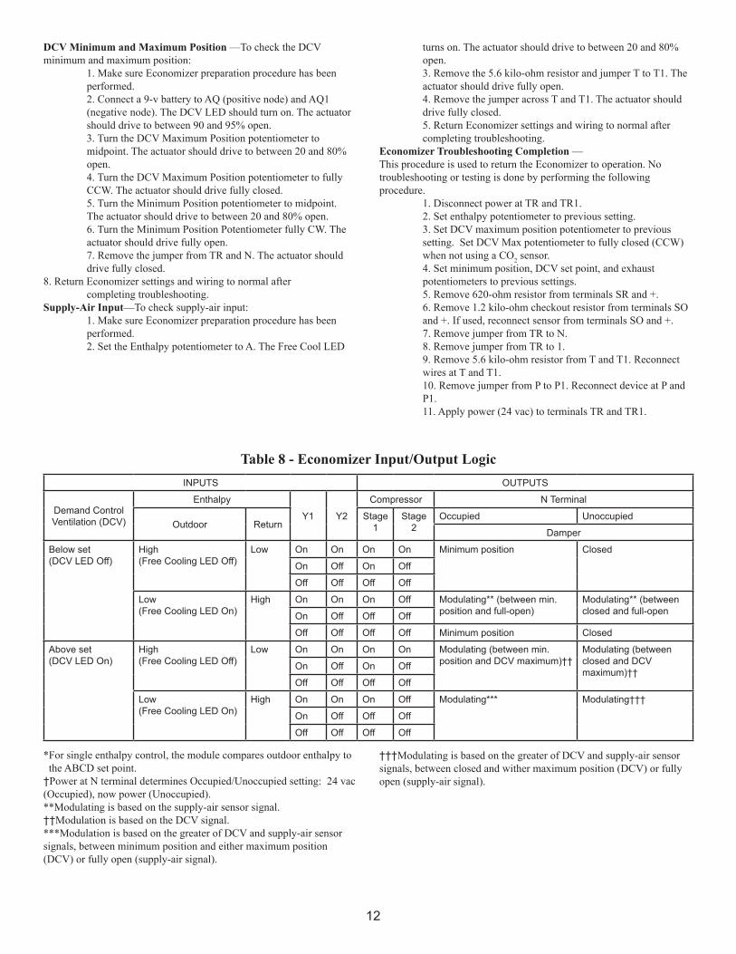
DCV Minimum and Maximum Position —To check the DCV minimum and maximum position: 1. Make sure Economizer preparation procedure has been performed. 2. Connect a 9-v battery to AQ (positive node) and AQ1 (negative node). The DCV LED should turn on. The actuator should drive to between 90 and 95% open. 3. Turn the DCV Maximum Position potentiometer to midpoint. The actuator should drive to between 20 and 80% open. 4. Turn the DCV Maximum Position potentiometer to fully CCW. The actuator should drive fully closed. 5. Turn the Minimum Position potentiometer to midpoint. The actuator should drive to between 20 and 80% open. 6. Turn the Minimum Position Potentiometer fully CW. The actuator should drive fully open. 7. Remove the jumper from TR and N. The actuator should drive fully closed.8. Return Economizer settings and wiring to normal after completing troubleshooting.Supply-Air Input—To check supply-air input: 1. Make sure Economizer preparation procedure has been performed. 2. Set the Enthalpy potentiometer to A. The Free Cool LED
*For single enthalpy control, the module compares outdoor enthalpy to the ABCD set point.†Power at N terminal determines Occupied/Unoccupied setting: 24 vac (Occupied), now power (Unoccupied).**Modulating is based on the supply-air sensor signal.††Modulation is based on the DCV signal.***Modulation is based on the greater of DCV and supply-air sensor signals, between minimum position and either maximum position (DCV) or fully open (supply-air signal).
†††Modulating is based on the greater of DCV and supply-air sensor signals, between closed and wither maximum position (DCV) or fully open (supply-air signal).
turns on. The actuator should drive to between 20 and 80% open. 3. Remove the 5.6 kilo-ohm resistor and jumper T to T1. The actuator should drive fully open. 4. Remove the jumper across T and T1. The actuator should drive fully closed. 5. Return Economizer settings and wiring to normal after completing troubleshooting.Economizer Troubleshooting Completion —This procedure is used to return the Economizer to operation. No troubleshooting or testing is done by performing the following procedure. 1. Disconnect power at TR and TR1. 2. Set enthalpy potentiometer to previous setting. 3. Set DCV maximum position potentiometer to previous setting. Set DCV Max potentiometer to fully closed (CCW) when not using a CO2 sensor. 4. Set minimum position, DCV set point, and exhaust potentiometers to previous settings. 5. Remove 620-ohm resistor from terminals SR and +. 6. Remove 1.2 kilo-ohm checkout resistor from terminals SO and +. If used, reconnect sensor from terminals SO and +. 7. Remove jumper from TR to N. 8. Remove jumper from TR to 1. 9. Remove 5.6 kilo-ohm resistor from T and T1. Reconnect wires at T and T1. 10. Remove jumper from P to P1. Reconnect device at P and P1. 11. Apply power (24 vac) to terminals TR and TR1.
INPUTS OUTPUTS
Demand ControlVentilation (DCV)
Enthalpy
Y1 Y2
Compressor N Terminal
Outdoor ReturnStage
1Stage
2Occupied Unoccupied
Damper
Below set(DCV LED Off)
High(Free Cooling LED Off)
Low On On On On Minimum position Closed
On Off On Off
Off Off Off Off
Low(Free Cooling LED On)
High On On On Off Modulating** (between min. position and full-open)
Modulating** (between closed and full-openOn Off Off Off
Off Off Off Off Minimum position Closed
Above set(DCV LED On)
High(Free Cooling LED Off)
Low On On On On Modulating (between min.position and DCV maximum)††
Modulating (betweenclosed and DCVmaximum)††
On Off On Off
Off Off Off Off
Low(Free Cooling LED On)
High On On On Off Modulating*** Modulating†††
On Off Off Off
Off Off Off Off
Table 8 - Economizer Input/Output Logic

13
WIR
ING
FO
R A
C A
ND
GA
S/EL
ECTR
IC M
OD
ELS

14
WIR
ING
FO
R H
EAT
PUM
P A
ND
DU
AL
FUEL
MO
DEL
S
Copyright 2010 CAC/BDP ● 7310 W.Morris St. ● Indianapolis, IN 46231 Printed in U.S.A. Edition Date: 09/10 Catalog No. IIK-CPECOMZR-15
Manufacturer reserves the right to discontinue, or change at any time, specifications or designs without notice and without incurring obligations Replaces: IIK-CPECOMZR-09