Embed Size (px)
Citation preview
Installation Manual and Operating Instructions
MD93 Series Digital Clock/USB Charger
Mid-Continent Instruments and Avionics
Mid-Continent Instrument Co., Inc. dba Mid-Continent Instruments and Avionics 9400 E. 34th Street N. Wichita, KS 67226 USA Manual Number 9018205 PH (316) 630-0101 FX (316) 630-0723 Revision A, July 15, 2014

FOREWORD
This manual provides information intended for use by persons who, in accordance with current regulatory requirements, are qualified to install this equipment. If further information is required, please contact:
Mid-Continent Instruments and Avionics Attn: Customer Service Dept.
9400 E. 34th Street N. Wichita, KS 67226 USA
PH (316) 630-0101 FX (316) 630-0723
www.mcico.com
We welcome your comments concerning this manual. Although every effort has been made to keep it free of errors, some may occur. When reporting a specific problem, please describe it briefly and include the manual part number, the paragraph/figure/table reference and the page number. Send your comments to:
Mid-Continent Instruments and Avionics Attn: Technical Publications
9400 E. 34th Street N. Wichita, KS 67226 USA
PH (316) 630-0101 FX (316) 630-0723
All products produced by Mid-Continent Instrument Co., Inc., including those identified as Mid-Continent Instruments and Avionics or True Blue Power, are designed and manufactured in Wichita, KS, USA.
© Copyright 2014 Mid-Continent Instrument Co., Inc.

REVISION HISTORY
ECO Revision Date Detail A 07/15/2014 Initial release.
TABLE OF CONTENTS
SECTION 1 GENERAL DESCRIPTION 6
1.1 INTRODUCTION 6
1.2 PHYSICAL ATTRIBUTES 6
1.3 UNIT ARCHITECTURE 7
1.4 TECHNICAL SPECIFICATIONS 7
1.4.1 ELECTRICAL ATTRIBUTES 7
1.4.2 PHYSICAL ATTRIBUTES 7
SECTION 2 PRE-INSTALLATION 8
2.1 COOLING 8
2.2 EQUIPMENT LOCATION 8
2.3 ROUTING OF CABLES 8
SECTION 3 INSTALLATION 9
3.1 GENERAL 9
3.2 PRE-INSTALLATION INSPECTION 9
3.3 PARTS 9
3.3.1 INCLUDED PARTS 9
3.3.2 OPTIONAL AVAILABLE PARTS 9
3.3.3 INSTALLER SUPPLIED PARTS 9
3.4 CABLE HARNESS 10
3.4.1 WIRE GAUGE SELECTION 10
3.4.2 PIN ASSIGNMENT INFORMATION 10
3.4.3 HARNESS VERIFICATION 10
3.5 INSTALLATION 11
3.5.1 DIMMING FUNCTIONS 11
SECTION 4 USB CHARGER OPERATION 12
4.1 DESCRIPTION 12
4.2 OPERATIONAL MODES 12
4.3 PROTECTIVE FEATURES 12
4.3.1 SHORT CIRCUIT PROTECTION 12
4.3.2 OVER-CURRENT PROTECTION 12
4.3.3 LOW INPUT VOLTAGE SHUTDOWN 12
4.3.4 OVER-TEMPERATURE 12
SECTION 5 CLOCK / CHRONOMETER OPERATION 13
5.1 DESCRIPTION 13
5.2 CONSTRUCTION 13
5.3 OPERATIONAL MODES 13
5.3.1 LOCAL TIME OPERATION / SETTING 14
5.3.2 UNIVERSAL TIME OPERATION / SETTING 15
5.3.3 FLIGHT TIMER 16
5.3.4 ELAPSED TIMER 17
5.3.5 DISPLAY TEST MODE 18
SECTION 6 CONFORMANCE 18
6.1 INSTRUCTIONS FOR CONTINUED AIR WORTHINESS 18
Mid-Continent Instruments and Avionics Revision A, July 10, 2014 Manual Number 9018205
6
SECTION 1 GENERAL DESCRIPTION
1.1 INTRODUCTION
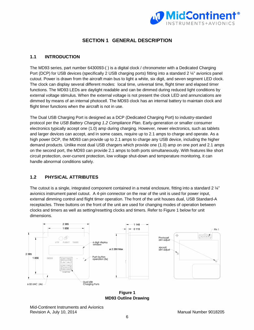
The MD93 series, part number 6430093-( ) is a digital clock / chronometer with a Dedicated Charging Port (DCP) for USB devices (specifically 2 USB charging ports) fitting into a standard 2 ¼” avionics panel cutout. Power is drawn from the aircraft main bus to light a white, six digit, and seven segment LED clock. The clock can display several different modes: local time, universal time, flight timer and elapsed timer functions. The MD93 LEDs are daylight readable and can be dimmed during reduced light conditions by external voltage stimulus. When the external voltage is not present the clock LED and annunciations are dimmed by means of an internal photocell. The MD93 clock has an internal battery to maintain clock and flight timer functions when the aircraft is not in use. The Dual USB Charging Port is designed as a DCP (Dedicated Charging Port) to industry-standard protocol per the USB Battery Charging 1.2 Compliance Plan. Early-generation or smaller consumer electronics typically accept one (1.0) amp during charging. However, newer electronics, such as tablets and larger devices can accept, and in some cases, require up to 2.1 amps to charge and operate. As a high power DCP, the MD93 can provide up to 2.1 amps to charge any USB device, including the higher demand products. Unlike most dual USB chargers which provide one (1.0) amp on one port and 2.1 amps on the second port, the MD93 can provide 2.1 amps to both ports simultaneously. With features like short circuit protection, over-current protection, low voltage shut-down and temperature monitoring, it can handle abnormal conditions safely.
1.2 PHYSICAL ATTRIBUTES
The cutout is a single, integrated component contained in a metal enclosure, fitting into a standard 2 ¼” avionics instrument panel cutout. A 4-pin connector on the rear of the unit is used for power input, external dimming control and flight timer operation. The front of the unit houses dual, USB Standard-A receptacles. Three buttons on the front of the unit are used for changing modes of operation between clocks and timers as well as setting/resetting clocks and timers. Refer to Figure 1 below for unit dimensions.
Figure 1
MD93 Outline Drawing
Mid-Continent Instruments and Avionics Revision A, July 10, 2014 Manual Number 9018205
7
1.3 UNIT ARCHITECTURE
The unit is comprised of two primary building blocks, a USB charger and digital clock. 10-32 VDC input power is regulated, 5 VDC via DC-DC converter used to power the USB charger and all clock/chronometer functions. A charging port controller manages power output for the dual USB charger port. An internal battery maintains clock functions when aircraft power is removed.
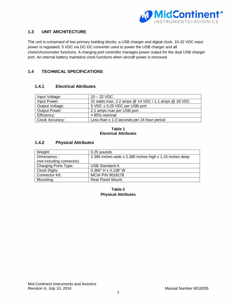
1.4 TECHNICAL SPECIFICATIONS
1.4.1 Electrical Attributes
Input Voltage: 10 – 32 VDC Input Power: 31 watts max; 2.2 amps @ 14 VDC / 1.1 amps @ 28 VDC Output Voltage: 5 VDC ± 0.25 VDC per USB port Output Power: 2.1 amps max per USB port Efficiency: ≈ 85% nominal Clock Accuracy: Less than ± 1.0 seconds per 24 hour period
Table 1 Electrical Attributes
1.4.2 Physical Attributes
Weight: 0.25 pounds Dimensions : (not including connector)
2.385 inches wide x 2.385 inches high x 1.15 inches deep
Charging Ports Type: USB Standard-A Clock Digits: 0.360” H x 0.138” W Connector Kit: MCIA P/N 9018178 Mounting: Rear Panel Mount
Table 2
Physical Attributes
Mid-Continent Instruments and Avionics Revision A, July 10, 2014 Manual Number 9018205
8
SECTION 2 PRE-INSTALLATION
2.1 COOLING
The MD93 will become warm when in use; however no external cooling is required. This is normal and within operational parameters. No special mounting considerations are required, although mounting to a metal surface can help dissipate any heat generated and extend the life of the product.
2.2 EQUIPMENT LOCATION
The MD93 Digital Clock / Dual USB Charging Port is designed for a circular rear panel mount configuration, allowing for installation in a cockpit or cabin. Clearance should be provided for the input mating connector which may require an additional inch of clearance beyond the rear of the unit.
2.3 ROUTING OF CABLES
Avoid sharp bends in cabling and routing near aircraft control cables. Avoid close proximity and contact with aircraft structures, avionics equipment or other obstructions that could chafe wires during flight and cause undesirable effects.
Mid-Continent Instruments and Avionics Revision A, July 10, 2014 Manual Number 9018205
9
SECTION 3 INSTALLATION
3.1 GENERAL
This section contains interconnect diagrams, mounting dimensions and other information pertaining to the installation of the MD93 Digital Clock / Dual USB Charging Port. After installation of cabling and before installation of the equipment, ensure that power and ground are applied to the proper pins specified in Section 3.4.2, Pin Assignment Information.
3.2 PRE-INSTALLATION INSPECTION
When unpacking this equipment, make a visual inspection for evidence of any damage that may have occurred during shipment.
3.3 PARTS
3.3.1 Included Parts
The following parts are included:
• Digital Clock / Dual USB Charging Port MCIA P/N 6420093-( ) • Installation Manual MCIA P/N 9018205 • Installation Kit MCIA P/N 9018178
o Mating Connector, 4-pin o Pins (6) (4 required, 2 spares) o Screws (5), #6-32 x 3/8” Flat Head (4 required, 1 spare)
3.3.2 Optional Available Parts
No additional parts or components are available.
3.3.3 Installer Supplied Parts
• Cable Harness Wire, See Section 3.4.1 for specifications • Circuit Breaker Recommendation 2.5 amp (1.5 amp may be sufficient for 28V aircraft)
(as needed per system requirements)
Mid-Continent Instruments and Avionics Revision A, July 10, 2014 Manual Number 9018205
10
3.4 CABLE HARNESS
Construct the cable harness following the instructions outlined below and per Tables 3 and 4. Refer to Section 2: Pre-Installation Considerations for routing precautions.
3.4.1 Wire Gauge Selection
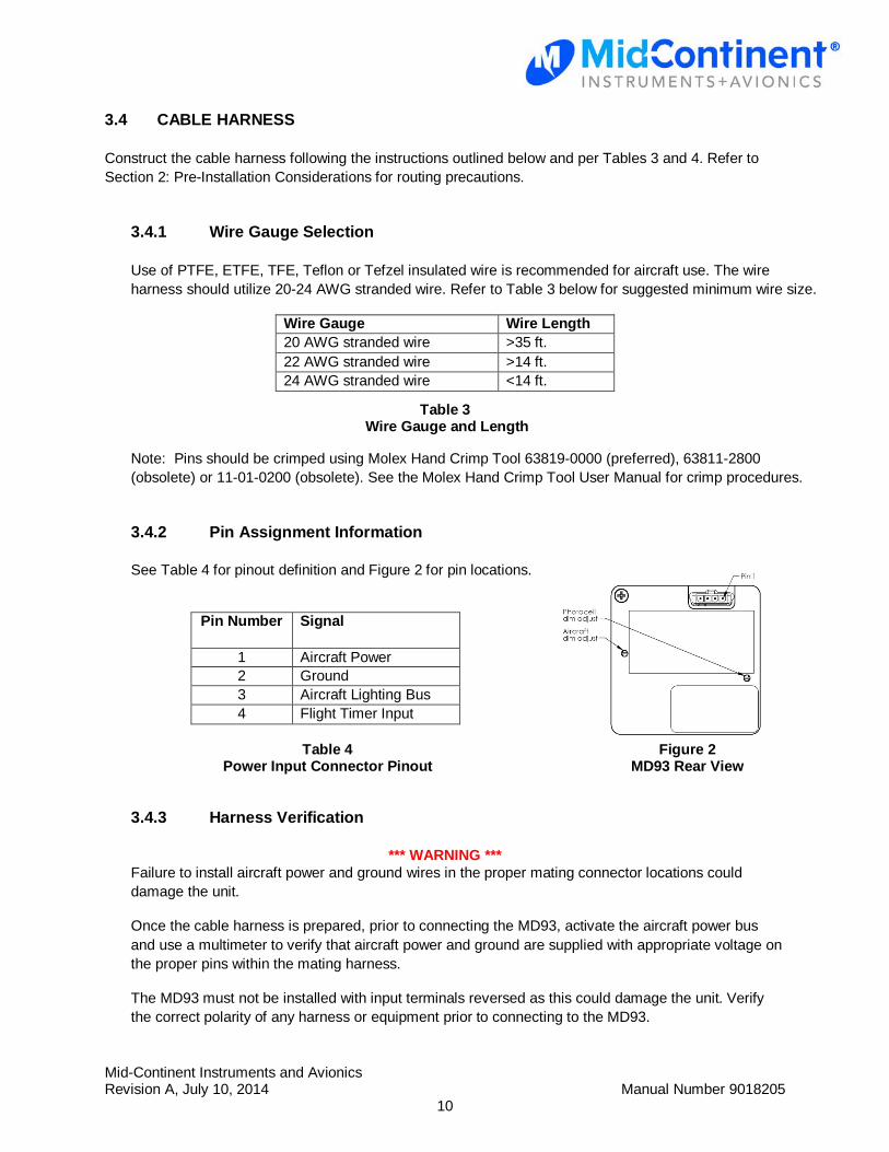
Use of PTFE, ETFE, TFE, Teflon or Tefzel insulated wire is recommended for aircraft use. The wire harness should utilize 20-24 AWG stranded wire. Refer to Table 3 below for suggested minimum wire size.
Wire Gauge Wire Length 20 AWG stranded wire >35 ft. 22 AWG stranded wire >14 ft. 24 AWG stranded wire <14 ft.
Table 3 Wire Gauge and Length
Note: Pins should be crimped using Molex Hand Crimp Tool 63819-0000 (preferred), 63811-2800 (obsolete) or 11-01-0200 (obsolete). See the Molex Hand Crimp Tool User Manual for crimp procedures.
3.4.2 Pin Assignment Information
See Table 4 for pinout definition and Figure 2 for pin locations.
Pin Number Signal
1 Aircraft Power 2 Ground 3 Aircraft Lighting Bus 4 Flight Timer Input
Table 4 Figure 2 Power Input Connector Pinout MD93 Rear View
3.4.3 Harness Verification
*** WARNING *** Failure to install aircraft power and ground wires in the proper mating connector locations could damage the unit.
Once the cable harness is prepared, prior to connecting the MD93, activate the aircraft power bus and use a multimeter to verify that aircraft power and ground are supplied with appropriate voltage on the proper pins within the mating harness.
The MD93 must not be installed with input terminals reversed as this could damage the unit. Verify the correct polarity of any harness or equipment prior to connecting to the MD93.
Mid-Continent Instruments and Avionics Revision A, July 10, 2014 Manual Number 9018205
11
3.5 INSTALLATION
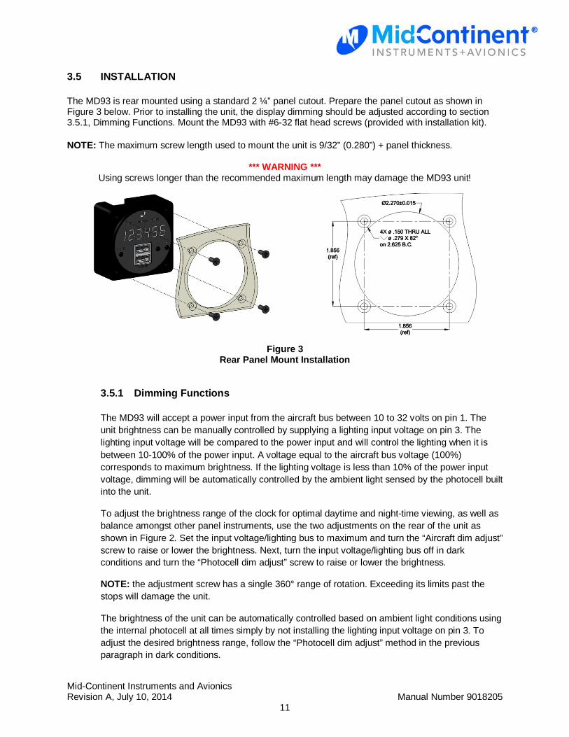
The MD93 is rear mounted using a standard 2 ¼” panel cutout. Prepare the panel cutout as shown in Figure 3 below. Prior to installing the unit, the display dimming should be adjusted according to section 3.5.1, Dimming Functions. Mount the MD93 with #6-32 flat head screws (provided with installation kit). NOTE: The maximum screw length used to mount the unit is 9/32” (0.280”) + panel thickness.
*** WARNING *** Using screws longer than the recommended maximum length may damage the MD93 unit!
Figure 3 Rear Panel Mount Installation
3.5.1 Dimming Functions
The MD93 will accept a power input from the aircraft bus between 10 to 32 volts on pin 1. The unit brightness can be manually controlled by supplying a lighting input voltage on pin 3. The lighting input voltage will be compared to the power input and will control the lighting when it is between 10-100% of the power input. A voltage equal to the aircraft bus voltage (100%) corresponds to maximum brightness. If the lighting voltage is less than 10% of the power input voltage, dimming will be automatically controlled by the ambient light sensed by the photocell built into the unit.
To adjust the brightness range of the clock for optimal daytime and night-time viewing, as well as balance amongst other panel instruments, use the two adjustments on the rear of the unit as shown in Figure 2. Set the input voltage/lighting bus to maximum and turn the “Aircraft dim adjust” screw to raise or lower the brightness. Next, turn the input voltage/lighting bus off in dark conditions and turn the “Photocell dim adjust” screw to raise or lower the brightness.
NOTE: the adjustment screw has a single 360° range of rotation. Exceeding its limits past the stops will damage the unit.
The brightness of the unit can be automatically controlled based on ambient light conditions using the internal photocell at all times simply by not installing the lighting input voltage on pin 3. To adjust the desired brightness range, follow the “Photocell dim adjust” method in the previous paragraph in dark conditions.
Mid-Continent Instruments and Avionics Revision A, July 10, 2014 Manual Number 9018205
12
SECTION 4 USB CHARGER OPERATION
4.1 DESCRIPTION
The MD93 Dual USB Charging Port converts aircraft DC input voltage within the range specified to a 5V DC output. This output power is applied to a dual USB-A connector in accordance with the USB Implementers Forum’s Dedicated Charging Port Compliance Plan.
4.2 OPERATIONAL MODES
The USB D+ and D- data lines communicate with the USB portable device to tell the device it is a dedicated charging port (DCP), capable of a higher current than a standard USB port. Each USB port on the MD93 can provide up to 2.1 amps (simultaneously) at 5 VDC.
4.3 PROTECTIVE FEATURES
4.3.1 Short Circuit Protection
The MD93 is capable of surviving a short circuit event without permanent damage. The unit enters an over-current condition so that the average current is significantly reduced and the device is protected.
4.3.2 Over-Current Protection
The MD93 monitors current draw individually on each port. During an over-current condition the output is turned off until the over-current condition is removed. Once the overcurrent condition is removed, the unit returns to normal operation.
4.3.3 Low Input Voltage Shutdown
If the input voltage applied to the MD93 drops below 10 VDC the unit will shut down until the applied voltage returns to a level within operating range.
4.3.4 Over-Temperature
If the temperature of the MD93 becomes elevated, the unit communicates with the USB portable device to reduce the charge current output to a 1.0 amp limit. When temperature returns to an acceptable level the unit automatically returns to a higher charge current as required (up to 2.1 amps).

Mid-Continent Instruments and Avionics Revision A, July 10, 2014 Manual Number 9018205
13
SECTION 5 CLOCK / CHRONOMETER OPERATION
5.1 DESCRIPTION
The clock/chronometer portion of the MD93 has 4 modes of operation, including local time, universal time, flight timer and elapsed timer. Specific operation instructions are covered in Section 5.3 (Operational Modes).
5.2 CONSTRUCTION
The clock has six digits that are 0.360” tall and 0.138” wide. Three user interface buttons (MODE, ̶ , and +) are utilized to switch between modes of operation, set clock time, and manage timer functions for the MD93. Backlit annunciations on the front bezel are included which indicate current mode of operation. When aircraft power is removed, the display clock and all annunciations will be turned off. The MD93 contains a battery that maintains clock functions (local time, universal time, flight timer) when aircraft power is removed for well over ten years.
5.3 OPERATIONAL MODES
The MD93 modes of operation for clock functions are, in order: local time, universal time, flight timer, and elapsed timer. Note: When the clock is in local time function, there are no annunciations to indicate as this is the default mode of operation. The mode button (MODE) is used to alternate between four different operational modes; specifically, local time > universal time > flight timer > elapsed timer > (and back to) local time, etc. This is performed by pressing the MODE button. Refer to Figure 5 - Modes of Operation for changing modes of operation.
LOCAL TIME
‘FLIGHT’ annunciation is displayed. Flight timer is displayed (always in tenths of hours – e.g. 5.9 or 258.7).
No annunciations for time mode are displayed. Local time is displayed.
FLIGHT TIMER
ELAPSED TIMER (STOPWATCH)
UNIVERSAL TIME
‘TIMER’ annunciation is displayed. The elapsed timer is displayed in hours, minutes, and seconds.
‘UTC’ annunciation is displayed. Universal time is displayed (always in 24 hour format)
Press MODE
Press MODE
Press MODE
Press MODE
Figure 4
Modes of Operation
Mid-Continent Instruments and Avionics Revision A, July 10, 2014 Manual Number 9018205
14
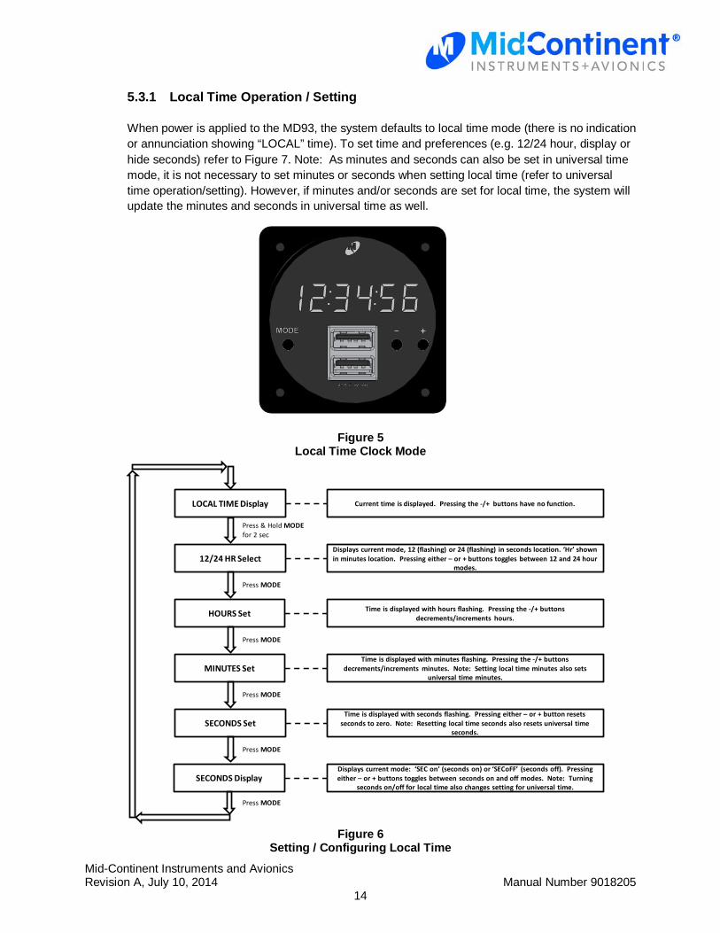
5.3.1 Local Time Operation / Setting
When power is applied to the MD93, the system defaults to local time mode (there is no indication or annunciation showing “LOCAL” time). To set time and preferences (e.g. 12/24 hour, display or hide seconds) refer to Figure 7. Note: As minutes and seconds can also be set in universal time mode, it is not necessary to set minutes or seconds when setting local time (refer to universal time operation/setting). However, if minutes and/or seconds are set for local time, the system will update the minutes and seconds in universal time as well.
Figure 5 Local Time Clock Mode
LOCAL TIME Display
Time is displayed with hours flashing. Pressing the -/+ buttons decrements/increments hours.
Current time is displayed. Pressing the -/+ buttons have no function.
HOURS Set
MINUTES Set
12/24 HR Select
Time is displayed with minutes flashing. Pressing the -/+ buttons decrements/increments minutes. Note: Setting local time minutes also sets
universal time minutes.
Displays current mode, 12 (flashing) or 24 (flashing) in seconds location. ‘Hr’ shown in minutes location. Pressing either – or + buttons toggles between 12 and 24 hour
modes.
Press & Hold MODEfor 2 sec
Press MODE
Press MODE
Press MODE
SECONDS DisplayDisplays current mode: ‘SEC on’ (seconds on) or ‘SECoFF’ (seconds off). Pressing either – or + buttons toggles between seconds on and off modes. Note: Turning
seconds on/off for local time also changes setting for universal time.
SECONDS SetTime is displayed with seconds flashing. Pressing either – or + button resets
seconds to zero. Note: Resetting local time seconds also resets universal time seconds.
Press MODE
Press MODE
Figure 6 Setting / Configuring Local Time
Mid-Continent Instruments and Avionics Revision A, July 10, 2014 Manual Number 9018205
15
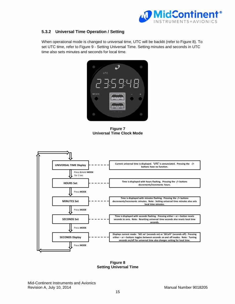
5.3.2 Universal Time Operation / Setting
When operational mode is changed to universal time, UTC will be backlit (refer to Figure 8). To set UTC time, refer to Figure 9 - Setting Universal Time. Setting minutes and seconds in UTC time also sets minutes and seconds for local time.
Figure 7 Universal Time Clock Mode
UNIVERSAL TIME Display
Time is displayed with hours flashing. Pressing the -/+ buttons decrements/increments hours.
Current universal time is displayed. ‘UTC’ is annunciated. Pressing the -/+ buttons have no function.
HOURS Set
MINUTES SetTime is displayed with minutes flashing. Pressing the -/+ buttons
decrements/increments minutes. Note: Setting universal time minutes also sets local time minutes.
Press &Hold MODEfor 2 sec
Press MODE
Press MODE
SECONDS DisplayDisplays current mode: ‘SEC on’ (seconds on) or ‘SECoFF’ (seconds off). Pressing either – or + buttons toggles between seconds on and off modes. Note: Turning
seconds on/off for universal time also changes setting for local time.
SECONDS SetTime is displayed with seconds flashing. Pressing either – or + button resets
seconds to zero. Note: Resetting universal time seconds also resets local time seconds.
Press MODE
Press MODE
Figure 8 Setting Universal Time
Mid-Continent Instruments and Avionics Revision A, July 10, 2014 Manual Number 9018205
16
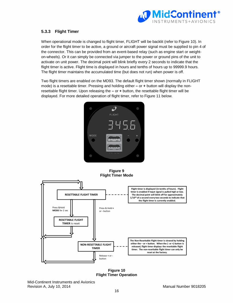
5.3.3 Flight Timer
When operational mode is changed to flight timer, FLIGHT will be backlit (refer to Figure 10). In order for the flight timer to be active, a ground or aircraft power signal must be supplied to pin 4 of the connector. This can be provided from an event-based relay (such as engine start or weight-on-wheels). Or it can simply be connected via jumper to the power or ground pins of the unit to activate on unit power. The decimal point will blink briefly every 2 seconds to indicate that the flight timer is active. Flight time is displayed in hours and tenths of hours up to 99999.9 hours. The flight timer maintains the accumulated time (but does not run) when power is off.
Two flight timers are enabled on the MD93. The default flight timer shown (normally in FLIGHT mode) is a resettable timer. Pressing and holding either – or + button will display the non-resettable flight timer. Upon releasing the – or + button, the resettable flight timer will be displayed. For more detailed operation of flight timer, refer to Figure 11 below.
Figure 9
Flight Timer Mode
RESETTABLE FLIGHT TIMER
Flight timer is displayed (in tenths of hours). Flight timer is enabled if input signal is pulled high or low.
The decimal point will blink off for approximately 1/10th of a second every two seconds to indicate that
the flight timer is currently enabled.
RESETTABLE FLIGHT TIMER is reset
Press &Hold MODE for 2 sec
NON-RESETTABLE FLIGHT TIMER
The Non-Resettable Flight timer is viewed by holding either the – or + button. When the (- or +) button is released, flight timer displays the resettable flight timer. The non-resettable flight timer can only be
reset at the factory.
Press & Hold +or - button
Release + or -button
Figure 10
Flight Timer Operation
Mid-Continent Instruments and Avionics Revision A, July 10, 2014 Manual Number 9018205
17
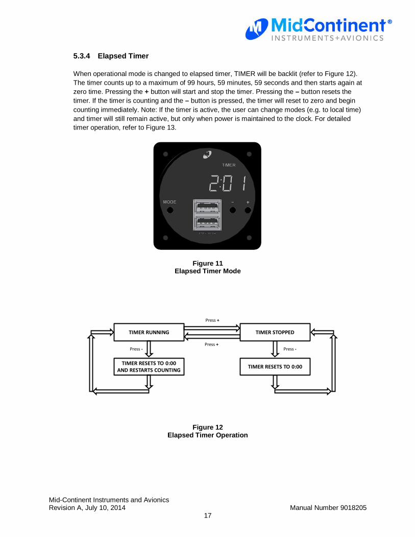
5.3.4 Elapsed Timer
When operational mode is changed to elapsed timer, TIMER will be backlit (refer to Figure 12). The timer counts up to a maximum of 99 hours, 59 minutes, 59 seconds and then starts again at zero time. Pressing the + button will start and stop the timer. Pressing the – button resets the timer. If the timer is counting and the – button is pressed, the timer will reset to zero and begin counting immediately. Note: If the timer is active, the user can change modes (e.g. to local time) and timer will still remain active, but only when power is maintained to the clock. For detailed timer operation, refer to Figure 13.
Figure 11 Elapsed Timer Mode
TIMER RUNNING
TIMER RESETS TO 0:00 AND RESTARTS COUNTING
Press - Press -
Press +
TIMER RESETS TO 0:00
TIMER STOPPED
Press +
Figure 12 Elapsed Timer Operation
Mid-Continent Instruments and Avionics Revision A, July 10, 2014 Manual Number 9018205
18
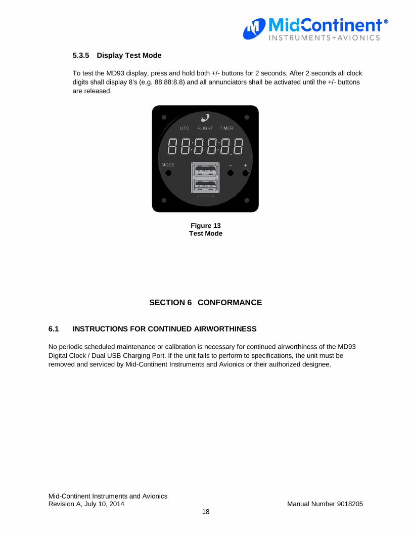
5.3.5 Display Test Mode
To test the MD93 display, press and hold both +/- buttons for 2 seconds. After 2 seconds all clock digits shall display 8’s (e.g. 88:88:8.8) and all annunciators shall be activated until the +/- buttons are released.
Figure 13 Test Mode
SECTION 6 CONFORMANCE
6.1 INSTRUCTIONS FOR CONTINUED AIRWORTHINESS
No periodic scheduled maintenance or calibration is necessary for continued airworthiness of the MD93 Digital Clock / Dual USB Charging Port. If the unit fails to perform to specifications, the unit must be removed and serviced by Mid-Continent Instruments and Avionics or their authorized designee.