Embed Size (px)
Citation preview

Instal lation Manual
Environment Accessories
HPX-1600Retractable Connection Port
and HPX Modules
Last Revised:4/27/2012

AMX Limited Warranty and DisclaimerThis Limited Warranty and Disclaimer extends only to products purchased directly from AMX or an AMX Authorized Partner which include AMX Dealers, Distributors, VIP’s or other AMX authorized entity.
AMX warrants its products to be free of defects in material and workmanship under normal use for three (3) years from the date of purchase, with the following exceptions:
• Electroluminescent and LCD Control Panels are warranted for three (3) years, except for the display and touch overlay compo-nents are warranted for a period of one (1) year.
• Disk drive mechanisms, pan/tilt heads, power supplies, and MX Series products are warranted for a period of one (1) year.
• AMX lighting products are guaranteed to switch on and off any load that is properly connected to our lighting products, as long as the AMX lighting products are under warranty. AMX also guarantees the control of dimmable loads that are properly con-nected to our lighting products. The dimming performance or quality there of is not guaranteed, impart due to the random combi-nations of dimmers, lamps and ballasts or transformers.
• AMX software is warranted for a period of ninety (90) days.
• Batteries and incandescent lamps are not covered under the warranty.
• AMX AutoPatch Epica, Modula, Modula Series4, Modula CatPro Series and 8Y-3000 product models will be free of defects in materials and manufacture at the time of sale and will remain in good working order for a period of three (3) years following the date of the original sales invoice from AMX. The three-year warranty period will be extended to the life of the product (Limited Lifetime Warranty) if the warranty card is filled out by the dealer and/or end user and returned to AMX so that AMX receives it within thirty (30) days of the installation of equipment but no later than six (6) months from original AMX sales invoice date. The life of the product extends until five (5) years after AMX ceases manufacturing the product model. The Limited Lifetime Warranty applies to products in their original installation only. If a product is moved to a different installation, the Limited Lifetime Warranty will no longer apply, and the product warranty will instead be the three (3) year Limited Warranty.
All products returned to AMX require a Return Material Authorization (RMA) number. The RMA number is obtained from the AMX RMA Department. The RMA number must be clearly marked on the outside of each box. The RMA is valid for a 30-day period. After the 30-day period the RMA will be cancelled. Any shipments received not consistent with the RMA, or after the RMA is cancelled, will be refused. AMX is not responsible for products returned without a valid RMA number.
AMX is not liable for any damages caused by its products or for the failure of its products to perform. This includes any lost profits, lost savings, incidental damages, or consequential damages. AMX is not liable for any claim made by a third party or by an AMX Autho-rized Partner for a third party.
This Limited Warranty does not apply to (a) any AMX product that has been modified, altered or repaired by an unauthorized agent or improperly transported, stored, installed, used, or maintained; (b) damage caused by acts of nature, including flood, erosion, or earth-quake; (c) damage caused by a sustained low or high voltage situation or by a low or high voltage disturbance, including brownouts, sags, spikes, or power outages; or (d) damage caused by war, vandalism, theft, depletion, or obsolescence.
This limitation of liability applies whether damages are sought, or a claim is made, under this warranty or as a tort claim (including negligence and strict product liability), a contract claim, or any other claim. This limitation of liability cannot be waived or amended by any person. This limitation of liability will be effective even if AMX or an authorized representative of AMX has been advised of the possibility of any such damages. This limitation of liability, however, will not apply to claims for personal injury.
Some states do not allow a limitation of how long an implied warranty last. Some states do not allow the limitation or exclusion of inci-dental or consequential damages for consumer products. In such states, the limitation or exclusion of the Limited Warranty may not apply. This Limited Warranty gives the owner specific legal rights. The owner may also have other rights that vary from state to state. The owner is advised to consult applicable state laws for full determination of rights.
EXCEPT AS EXPRESSLY SET FORTH IN THIS WARRANTY, AMX MAKES NO OTHER WARRANTIES, EXPRESSED OR IMPLIED, INCLUDING ANY IMPLIED WARRANTIES OF MERCHANTABILITY OR FITNESS FOR A PARTICULAR PURPOSE. AMX EXPRESSLY DISCLAIMS ALL WARRANTIES NOT STATED IN THIS LIMITED WARRANTY. ANY IMPLIED WARRANTIES THAT MAY BE IMPOSED BY LAW ARE LIMITED TO THE TERMS OF THIS LIMITED WARRANTY. EXCEPT AS OTHERWISE LIMITED BY APPLICABLE LAW, AMX RESERVES THE RIGHT TO MODIFY OR DISCONTINUE DESIGNS, SPECIFICATIONS, WARRAN-TIES, PRICES, AND POLICIES WITHOUT NOTICE.
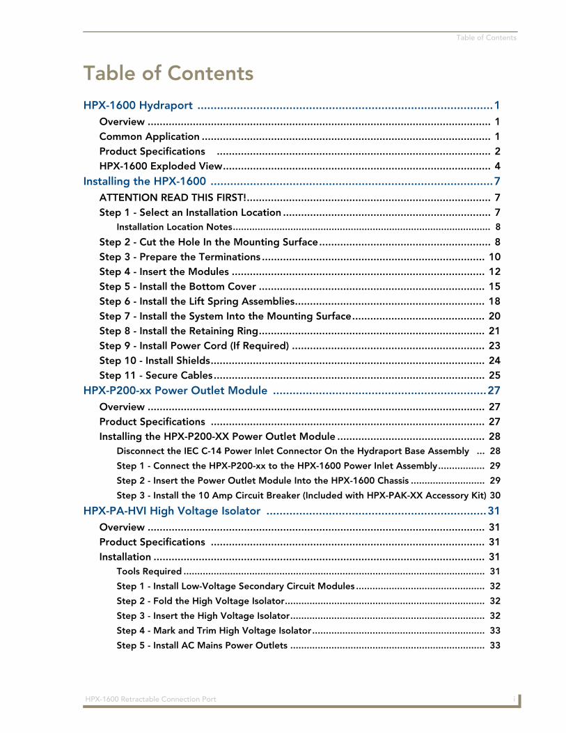
Table of Contents
Table of ContentsHPX-1600 Hydraport ..........................................................................................1
Overview .................................................................................................................. 1Common Application ................................................................................................ 1Product Specifications ........................................................................................... 2HPX-1600 Exploded View......................................................................................... 4
Installing the HPX-1600 ......................................................................................7ATTENTION READ THIS FIRST!................................................................................. 7Step 1 - Select an Installation Location ..................................................................... 7
Installation Location Notes.............................................................................................. 8
Step 2 - Cut the Hole In the Mounting Surface......................................................... 8Step 3 - Prepare the Terminations .......................................................................... 10Step 4 - Insert the Modules .................................................................................... 12Step 5 - Install the Bottom Cover ........................................................................... 15Step 6 - Install the Lift Spring Assemblies............................................................... 18Step 7 - Install the System Into the Mounting Surface............................................ 20Step 8 - Install the Retaining Ring........................................................................... 21Step 9 - Install Power Cord (If Required) ................................................................ 23Step 10 - Install Shields........................................................................................... 24Step 11 - Secure Cables.......................................................................................... 25
HPX-P200-xx Power Outlet Module .................................................................27Overview ................................................................................................................ 27Product Specifications ........................................................................................... 27Installing the HPX-P200-XX Power Outlet Module ................................................. 28
Disconnect the IEC C-14 Power Inlet Connector On the Hydraport Base Assembly ... 28
Step 1 - Connect the HPX-P200-xx to the HPX-1600 Power Inlet Assembly................. 29
Step 2 - Insert the Power Outlet Module Into the HPX-1600 Chassis ........................... 29
Step 3 - Install the 10 Amp Circuit Breaker (Included with HPX-PAK-XX Accessory Kit) 30
HPX-PA-HVI High Voltage Isolator ...................................................................31Overview ................................................................................................................ 31Product Specifications ........................................................................................... 31Installation .............................................................................................................. 31
Tools Required .............................................................................................................. 31
Step 1 - Install Low-Voltage Secondary Circuit Modules ............................................... 32
Step 2 - Fold the High Voltage Isolator......................................................................... 32
Step 3 - Insert the High Voltage Isolator....................................................................... 32
Step 4 - Mark and Trim High Voltage Isolator............................................................... 33
Step 5 - Install AC Mains Power Outlets ....................................................................... 33
iHPX-1600 Retractable Connection Port

Table of Contents
ii HPX-1600 Retractable Connection Port
HPX-1600 Hydraport
HPX-1600 Hydraport
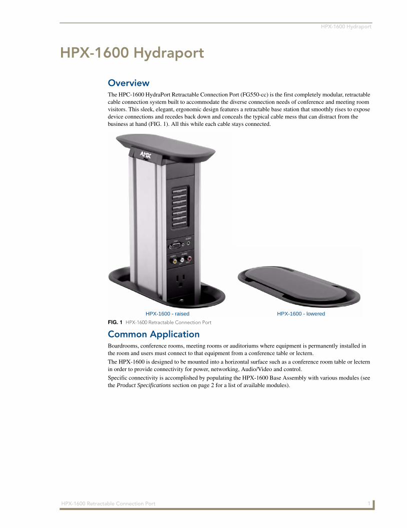
OverviewThe HPC-1600 HydraPort Retractable Connection Port (FG550-cc) is the first completely modular, retractable cable connection system built to accommodate the diverse connection needs of conference and meeting room visitors. This sleek, elegant, ergonomic design features a retractable base station that smoothly rises to expose device connections and recedes back down and conceals the typical cable mess that can distract from the business at hand (FIG. 1). All this while each cable stays connected.
Common ApplicationBoardrooms, conference rooms, meeting rooms or auditoriums where equipment is permanently installed in the room and users must connect to that equipment from a conference table or lectern.
The HPX-1600 is designed to be mounted into a horizontal surface such as a conference room table or lectern in order to provide connectivity for power, networking, Audio/Video and control.
Specific connectivity is accomplished by populating the HPX-1600 Base Assembly with various modules (see the Product Specifications section on page 2 for a list of available modules).
FIG. 1 HPX-1600 Retractable Connection Port
HPX-1600 - raised HPX-1600 - lowered
1HPX-1600 Retractable Connection Port
HPX-1600 Hydraport
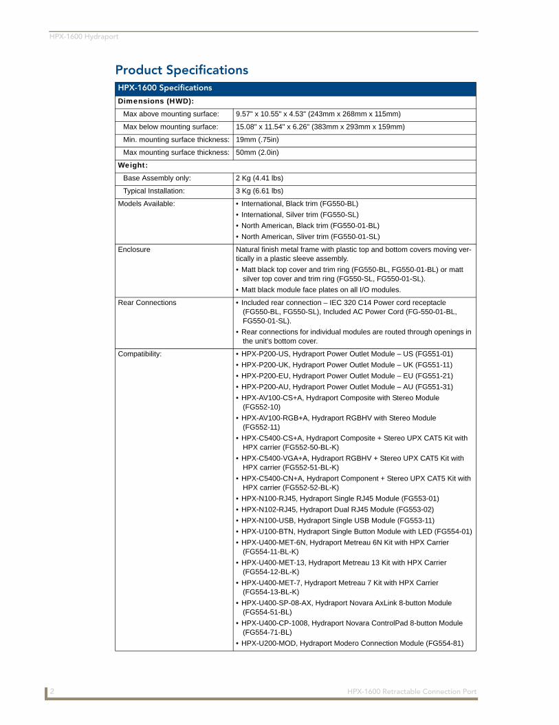
Product Specifications HPX-1600 Specifications
Dimensions (HWD):
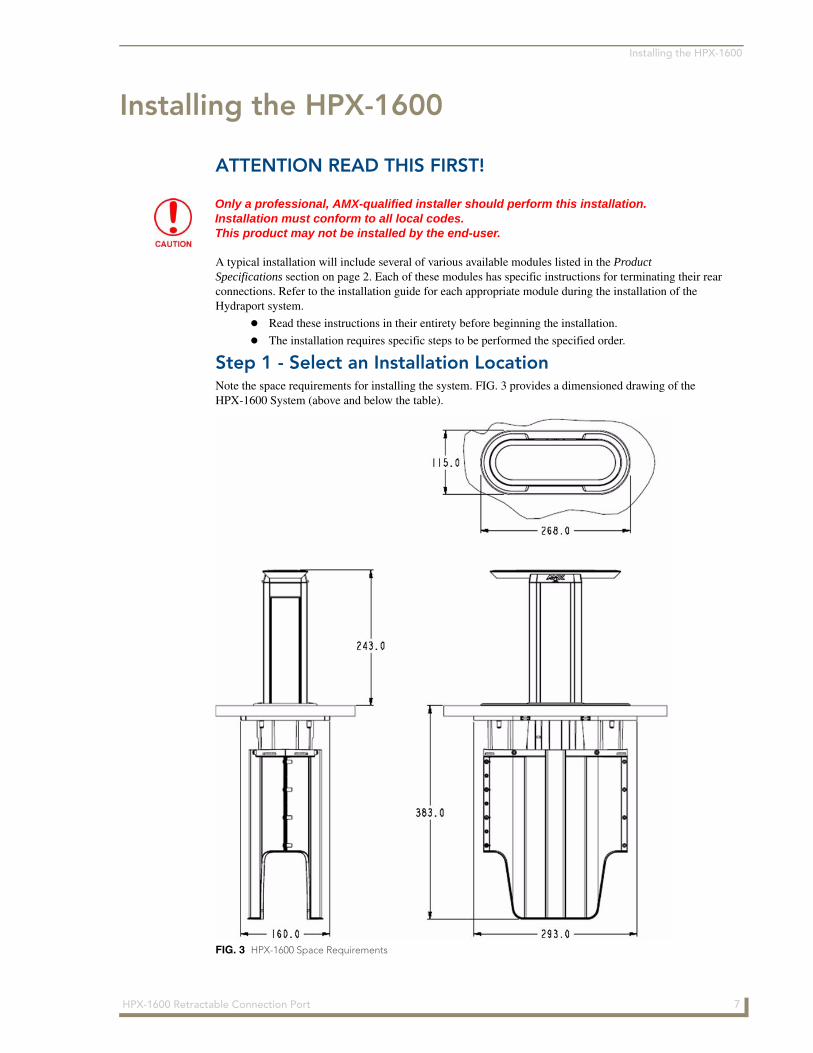
Max above mounting surface: 9.57" x 10.55" x 4.53" (243mm x 268mm x 115mm)
Max below mounting surface: 15.08" x 11.54" x 6.26" (383mm x 293mm x 159mm)
Min. mounting surface thickness: 19mm (.75in)
Max mounting surface thickness: 50mm (2.0in)
Weight:
Base Assembly only: 2 Kg (4.41 lbs)
Typical Installation: 3 Kg (6.61 lbs)
Models Available: • International, Black trim (FG550-BL)
• International, Silver trim (FG550-SL)
• North American, Black trim (FG550-01-BL)
• North American, Sliver trim (FG550-01-SL)
Enclosure Natural finish metal frame with plastic top and bottom covers moving ver-tically in a plastic sleeve assembly.
• Matt black top cover and trim ring (FG550-BL, FG550-01-BL) or matt silver top cover and trim ring (FG550-SL, FG550-01-SL).
• Matt black module face plates on all I/O modules.
Rear Connections • Included rear connection – IEC 320 C14 Power cord receptacle (FG550-BL, FG550-SL), Included AC Power Cord (FG-550-01-BL, FG550-01-SL).
• Rear connections for individual modules are routed through openings in the unit’s bottom cover.
Compatibility: • HPX-P200-US, Hydraport Power Outlet Module – US (FG551-01)
• HPX-P200-UK, Hydraport Power Outlet Module – UK (FG551-11)
• HPX-P200-EU, Hydraport Power Outlet Module – EU (FG551-21)
• HPX-P200-AU, Hydraport Power Outlet Module – AU (FG551-31)
• HPX-AV100-CS+A, Hydraport Composite with Stereo Module (FG552-10)
• HPX-AV100-RGB+A, Hydraport RGBHV with Stereo Module (FG552-11)
• HPX-C5400-CS+A, Hydraport Composite + Stereo UPX CAT5 Kit with HPX carrier (FG552-50-BL-K)
• HPX-C5400-VGA+A, Hydraport RGBHV + Stereo UPX CAT5 Kit with HPX carrier (FG552-51-BL-K)
• HPX-C5400-CN+A, Hydraport Component + Stereo UPX CAT5 Kit with HPX carrier (FG552-52-BL-K)
• HPX-N100-RJ45, Hydraport Single RJ45 Module (FG553-01)
• HPX-N102-RJ45, Hydraport Dual RJ45 Module (FG553-02)
• HPX-N100-USB, Hydraport Single USB Module (FG553-11)
• HPX-U100-BTN, Hydraport Single Button Module with LED (FG554-01)
• HPX-U400-MET-6N, Hydraport Metreau 6N Kit with HPX Carrier (FG554-11-BL-K)
• HPX-U400-MET-13, Hydraport Metreau 13 Kit with HPX Carrier (FG554-12-BL-K)
• HPX-U400-MET-7, Hydraport Metreau 7 Kit with HPX Carrier (FG554-13-BL-K)
• HPX-U400-SP-08-AX, Hydraport Novara AxLink 8-button Module (FG554-51-BL)
• HPX-U400-CP-1008, Hydraport Novara ControlPad 8-button Module (FG554-71-BL)
• HPX-U200-MOD, Hydraport Modero Connection Module (FG554-81)
2 HPX-1600 Retractable Connection Port
HPX-1600 Hydraport
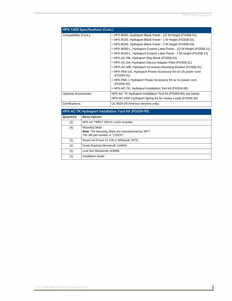
HPX-1600 Specifications (Cont.)
Compatibility (Cont.): • HPX-B050, Hydraport Blank Panel - 1/2 M Height (FG558-01)
• HPX-B100, Hydraport Blank Panel - 1 M Height (FG558-02)
• HPX-B200, Hydraport Blank Panel - 2 M Height (FG558-03)
• HPX-B050-L, Hydraport Custom Label Panel - 1/2 M Height (FG558-11)
• HPX-B100-L, Hydraport Custom Label Panel - 1 M Height (FG558-12)
• HPX-AC-SB, Hydraport Stop Block (FG559-01)
• HPX-AC-DA, Hydraport Decora Adapter Plate (FG559-11)
• HPX-AC-MB, Hydraport Accessory Mounting Bracket (FG559-21)
• HPX-PAK-US, Hydraport Power Accessory Kit w/ US power cord (FG559-31)
• HPX-PAK-I, Hydraport Power Accessory Kit w/ no power cord (FG559-32)
• HPX-AC-TK, Hydraport Installation Tool Kit (FG559-90)
Optional Accessories: HPX-AC-TK Hydraport Installation Tool Kit (FG559-90) see below.
HPX-AC-HSP Hydraport Spring Kit for Heavy Loads (FG559-42)
Certifications: UL 962A (N America versions only)
HPX-AC-TK Hydraport Installation Tool Kit (FG559-90)
Quantity Description
(1) HPX-AC-TMPLT 559-91 router template
(4) Mounting Strips
Note: The Mounting Strips are manufactured by 3M™. The 3M part number is “17021P”.
(1) Router bit (Freud 12-128 or Whiteside 1072)
(1) Guide Bushing (Woodcraft 144693)
(1) Lock Nut (Woodcraft 144696)
(1) Installation Guide
3HPX-1600 Retractable Connection Port

HPX-1600 Hydraport
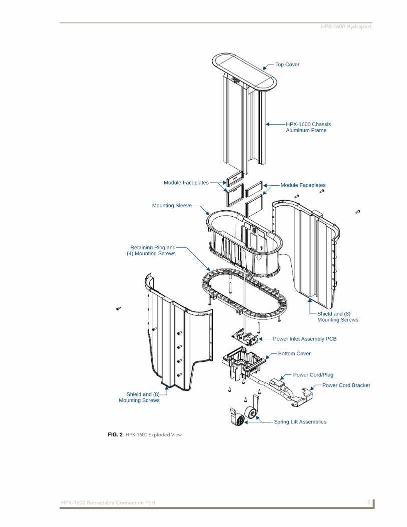
HPX-1600 Exploded ViewFIG. 2 provides an exploded view of the HPX-1600 Hydraport System, with the main components referenced in this document labelled. Use this diagram for reference while following the instructions provided in this document.
4 HPX-1600 Retractable Connection Port
HPX-1600 Hydraport
FIG. 2 HPX-1600 Exploded View
Shield and (8)Mounting Screws
Shield and (8)Mounting Screws
Power Cord/Plug
Power Cord Bracket
Retaining Ring and(4) Mounting Screws
Mounting Sleeve
Module Faceplates Module Faceplates
Spring Lift Assemblies
Bottom Cover
Top Cover
HPX-1600 ChassisAluminum Frame
Power Inlet Assembly PCB
5HPX-1600 Retractable Connection Port

HPX-1600 Hydraport
6 HPX-1600 Retractable Connection Port
Installing the HPX-1600
Installing the HPX-1600
ATTENTION READ THIS FIRST!
A typical installation will include several of various available modules listed in the Product Specifications section on page 2. Each of these modules has specific instructions for terminating their rear connections. Refer to the installation guide for each appropriate module during the installation of the Hydraport system.
Read these instructions in their entirety before beginning the installation.
The installation requires specific steps to be performed the specified order.
Step 1 - Select an Installation LocationNote the space requirements for installing the system. FIG. 3 provides a dimensioned drawing of the HPX-1600 System (above and below the table).
Only a professional, AMX-qualified installer should perform this installation. Installation must conform to all local codes. This product may not be installed by the end-user.
FIG. 3 HPX-1600 Space Requirements
7HPX-1600 Retractable Connection Port
Installing the HPX-1600
Installation Location NotesThe Hydraport system requires a mounting surface from 19mm (.75in) to 50mm (2.0in) thick.
The Hydraport system requires at least 383mm x 293mm x 159mm (zzin x xxin x yyin) of space below the mounting surface.
If the system is to be mounted within a column, pillar or other enclosed space below the mounting surface, please note that final assembly and termination will require the installer to have access to this space below the mounting surface.
Care should also be taken to ensure that the system does not interfere with the normal use of the work space.
For example, on a table or work surface, ensure that the system does not interfere with the user's legs when they are seated at the table. Even when the system is deployed in the up position, the mounting system and shields occupy the entire space requirement below the table.
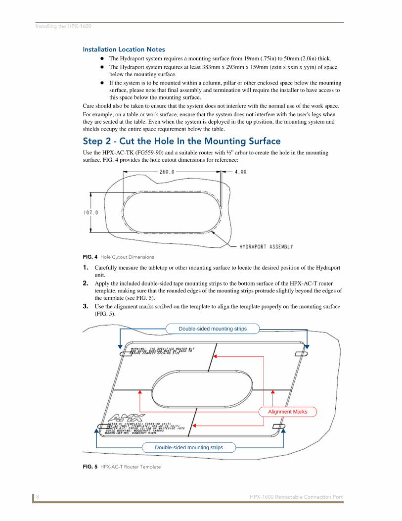
Step 2 - Cut the Hole In the Mounting SurfaceUse the HPX-AC-TK (FG559-90) and a suitable router with ½” arbor to create the hole in the mounting surface. FIG. 4 provides the hole cutout dimensions for reference:
1. Carefully measure the tabletop or other mounting surface to locate the desired position of the Hydraport unit.
2. Apply the included double-sided tape mounting strips to the bottom surface of the HPX-AC-T router template, making sure that the rounded edges of the mounting strips protrude slightly beyond the edges of the template (see FIG. 5).
3. Use the alignment marks scribed on the template to align the template properly on the mounting surface (FIG. 5).
FIG. 4 Hole Cutout Dimensions
FIG. 5 HPX-AC-T Router Template
Double-sided mounting strips
Double-sided mounting strips
Alignment Marks
8 HPX-1600 Retractable Connection Port
Installing the HPX-1600
Note that due to the guide bushing and router bit, the final cutout will be smaller than the opening in the template. The cutout in the mounting surface will be offset to the inside of the template opening by 1/8th inch (3.2 mm) on all sides.
Note both the position and orientation of the template relative to the table top or other mounting surface.
Note that very little clearance exists between the Hydraport assembly and the hole cutout in the mounting surface. Take care to align the cutout carefully with the edges or other appropriate features in the table or mounting surface. If the cutout is misaligned, the installed unit will be misaligned.
4. Install the router guide bushing into the base of a suitable router.
The router should be equipped with a ½ inch (12.2mm) collet and a baseplate capable of accepting a standard 1 3/16 inch (30.2mm) guide bushing.
Install the router bit into the router with an appropriate portion of the bit exposed below the guide bushing.
5. Switch the router on and carefully lower (plunge) the router bit into the mounting surface within the template opening.
6. Move the router against the template opening such that the guide bushing follows along the template opening.
7. Carefully follow the template opening with the guide bushing in a clockwise fashion such that the cutting action of the router bit is acting against the motion of the router.
8. Make several passes with the router, guide bushing and router bit.
9. Lower the router bit in small increments to remove a suitable amount of material on each pass.
Take care to ensure that the top surface of the mounting surface is not damaged beyond the width of the trim bezel as the cutout is made.
Make sure the bit or cutting tool used is appropriate for the material to be cut and will not tear or chip the top surface.
AMX does NOT recommend using a Jigsaw to make the final cutout.
Note that the process of making the cutout will create substantial dust and prepare the environment appropriately.
10. Finally, remove template by pulling firmly on the rounded edges of the double-sided tape mounting strips until they release from the tabletop and template.
Ensure the template is held securely on the mounting surface. If the template moves during the cutting process, the cutout will be enlarged and will likely exceed the trim bezel of the Hydraport base assembly, requiring extensive repair to the mounting surface.
Trying to cut too deep in any one pass may result in damage to the mounting surface.
9HPX-1600 Retractable Connection Port
Installing the HPX-1600
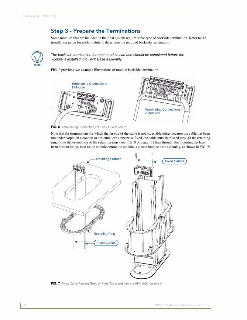
Step 3 - Prepare the TerminationsSome modules that are included in the final system require some type of backside termination. Refer to the installation guide for each module to determine the required backside termination.
FIG. 6 provides two example illustrations of module backside termination.
Note that for terminations for which the far end of the cable is not accessible either because the cable has been run under carpet, in a conduit or structure, or is otherwise fixed, the cable must be placed through the retaining ring, (note the orientation of the retaining ring - see FIG. 8 on page 11) then through the mounting surface from bottom to top, then to the module before the module is placed into the base assembly, as shown in FIG. 7:
The backside termination for each module can and should be completed before the module is installed into HPX Base assembly.
FIG. 6 Terminating Connections of 1 or 2 HPX Modules
FIG. 7 Fixed Cable Passing Through Ring, Table and Into the HPX-1600 Assembly
Terminating Connections -
Terminating Connections - 2 Modules
1 Module
Mounting Surface
Fixed Cables
Retaining Ring
Fixed Cables
10 HPX-1600 Retractable Connection Port
Installing the HPX-1600
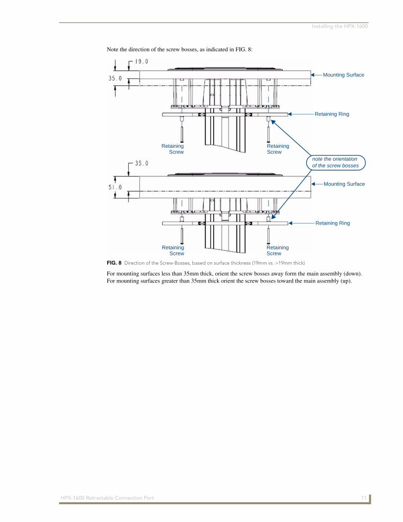
Note the direction of the screw bosses, as indicated in FIG. 8:
For mounting surfaces less than 35mm thick, orient the screw bosses away form the main assembly (down). For mounting surfaces greater than 35mm thick orient the screw bosses toward the main assembly (up).
FIG. 8 Direction of the Screw-Bosses, based on surface thickness (19mm vs. >19mm thick)
note the orientationof the screw bosses
Retaining Ring
Mounting Surface
Retaining Ring
Mounting Surface
RetainingScrew
RetainingScrew
RetainingScrew
RetainingScrew
11HPX-1600 Retractable Connection Port
Installing the HPX-1600
Step 4 - Insert the Modules
1. Latch the system in the closed (down) position.
2. Place the HPX-1600 Base assembly upside down on a suitable surface to ensure the top cover is not scratched.
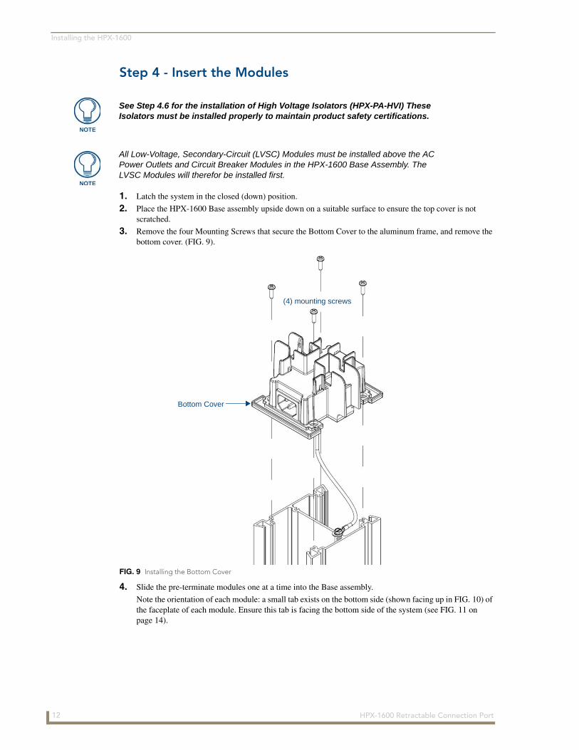
3. Remove the four Mounting Screws that secure the Bottom Cover to the aluminum frame, and remove the bottom cover. (FIG. 9).
4. Slide the pre-terminate modules one at a time into the Base assembly.
Note the orientation of each module: a small tab exists on the bottom side (shown facing up in FIG. 10) of the faceplate of each module. Ensure this tab is facing the bottom side of the system (see FIG. 11 on page 14).
See Step 4.6 for the installation of High Voltage Isolators (HPX-PA-HVI) These Isolators must be installed properly to maintain product safety certifications.
All Low-Voltage, Secondary-Circuit (LVSC) Modules must be installed above the AC Power Outlets and Circuit Breaker Modules in the HPX-1600 Base Assembly. The LVSC Modules will therefor be installed first.
FIG. 9 Installing the Bottom Cover
Bottom Cover
(4) mounting screws
12 HPX-1600 Retractable Connection Port
Installing the HPX-1600
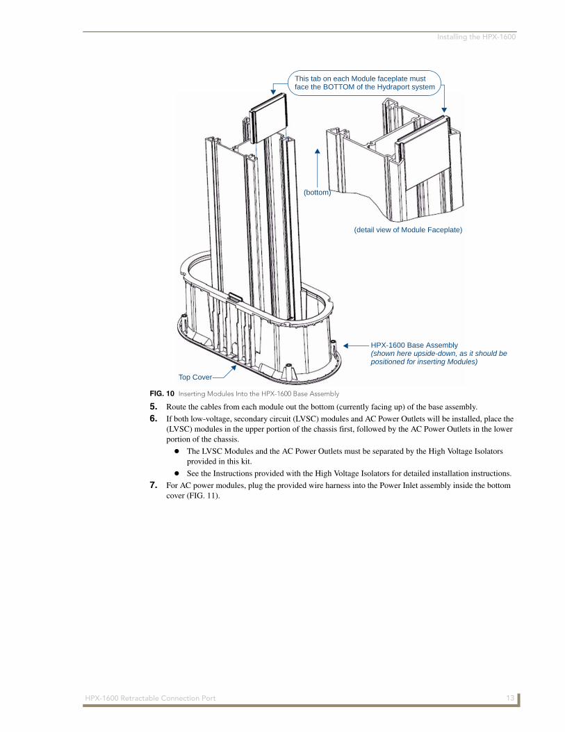
5. Route the cables from each module out the bottom (currently facing up) of the base assembly.
6. If both low-voltage, secondary circuit (LVSC) modules and AC Power Outlets will be installed, place the (LVSC) modules in the upper portion of the chassis first, followed by the AC Power Outlets in the lower portion of the chassis.
The LVSC Modules and the AC Power Outlets must be separated by the High Voltage Isolators provided in this kit.
See the Instructions provided with the High Voltage Isolators for detailed installation instructions.
7. For AC power modules, plug the provided wire harness into the Power Inlet assembly inside the bottom cover (FIG. 11).
FIG. 10 Inserting Modules Into the HPX-1600 Base Assembly
Top Cover
(detail view of Module Faceplate)
This tab on each Module faceplate mustface the BOTTOM of the Hydraport system
HPX-1600 Base Assembly(shown here upside-down, as it should bepositioned for inserting Modules)
(bottom)
13HPX-1600 Retractable Connection Port
Installing the HPX-1600
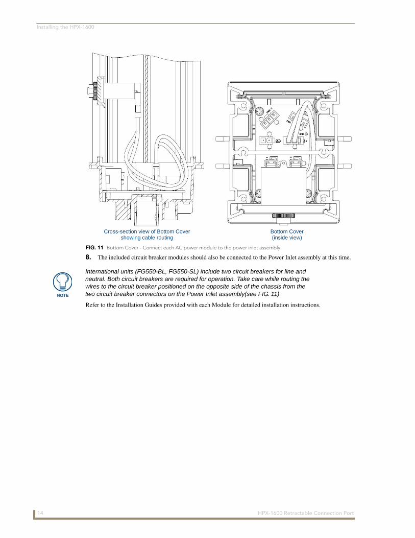
8. The included circuit breaker modules should also be connected to the Power Inlet assembly at this time.
Refer to the Installation Guides provided with each Module for detailed installation instructions.
FIG. 11 Bottom Cover - Connect each AC power module to the power inlet assembly
Bottom Cover(inside view)
Cross-section view of Bottom Covershowing cable routing
International units (FG550-BL, FG550-SL) include two circuit breakers for line and neutral. Both circuit breakers are required for operation. Take care while routing the wires to the circuit breaker positioned on the opposite side of the chassis from the two circuit breaker connectors on the Power Inlet assembly(see FIG. 11)
14 HPX-1600 Retractable Connection Port
Installing the HPX-1600
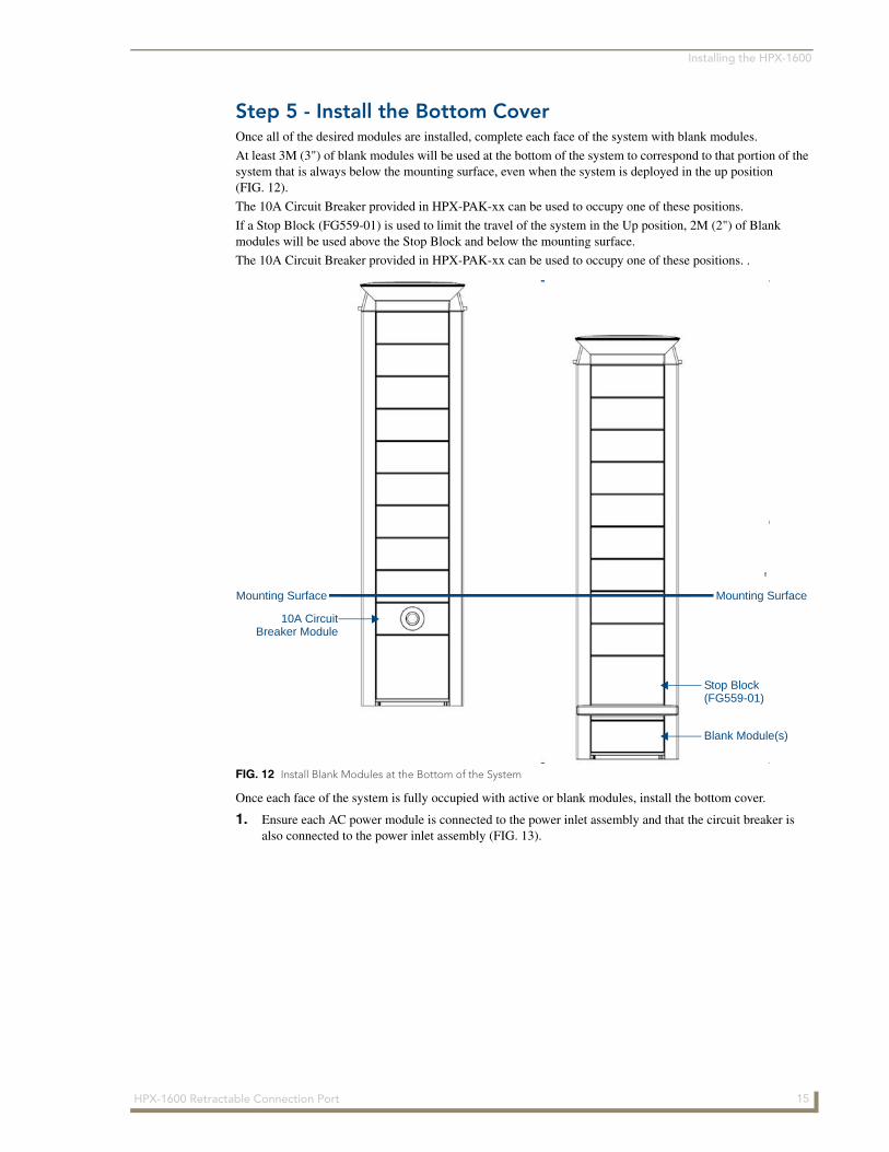
Step 5 - Install the Bottom CoverOnce all of the desired modules are installed, complete each face of the system with blank modules.
At least 3M (3") of blank modules will be used at the bottom of the system to correspond to that portion of the system that is always below the mounting surface, even when the system is deployed in the up position (FIG. 12).
The 10A Circuit Breaker provided in HPX-PAK-xx can be used to occupy one of these positions.
If a Stop Block (FG559-01) is used to limit the travel of the system in the Up position, 2M (2") of Blank modules will be used above the Stop Block and below the mounting surface.
The 10A Circuit Breaker provided in HPX-PAK-xx can be used to occupy one of these positions. .
Once each face of the system is fully occupied with active or blank modules, install the bottom cover.
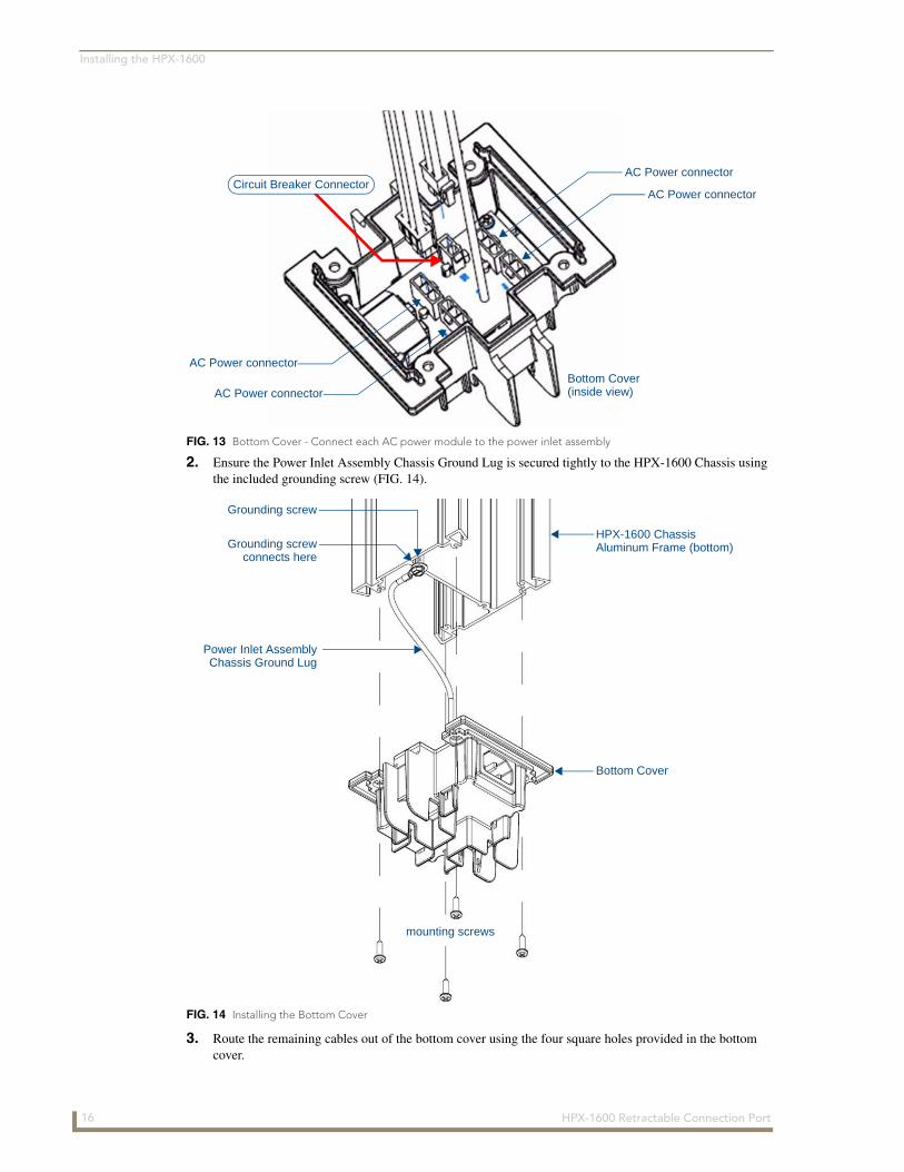
1. Ensure each AC power module is connected to the power inlet assembly and that the circuit breaker is also connected to the power inlet assembly (FIG. 13).
FIG. 12 Install Blank Modules at the Bottom of the System
Mounting SurfaceMounting Surface
10A CircuitBreaker Module
Stop Block(FG559-01)
Blank Module(s)
15HPX-1600 Retractable Connection Port
Installing the HPX-1600
2. Ensure the Power Inlet Assembly Chassis Ground Lug is secured tightly to the HPX-1600 Chassis using the included grounding screw (FIG. 14).
3. Route the remaining cables out of the bottom cover using the four square holes provided in the bottom cover.
FIG. 13 Bottom Cover - Connect each AC power module to the power inlet assembly
FIG. 14 Installing the Bottom Cover
Bottom Cover(inside view)
AC Power connector
AC Power connector
AC Power connector
AC Power connector
Circuit Breaker Connector
Bottom Cover
HPX-1600 ChassisGrounding screw
connects here
Grounding screw
Power Inlet Assembly
mounting screws
Aluminum Frame (bottom)
Chassis Ground Lug
16 HPX-1600 Retractable Connection Port

Installing the HPX-1600
4. Secure the bottom cover to the aluminum frame using the four provided screws.
5. Secure the cables exiting the bottom cover using the provided wire ties (FIG. 15).
FIG. 15 Bottom Cover - Installed With Cables Exiting and Secured
HPX-1600 ChassisAluminum Frame (bottom)
Wire Tie
Wire Tie
Bottom Cover(secured with 4mounting screws)
Cable
Cable
17HPX-1600 Retractable Connection Port
Installing the HPX-1600
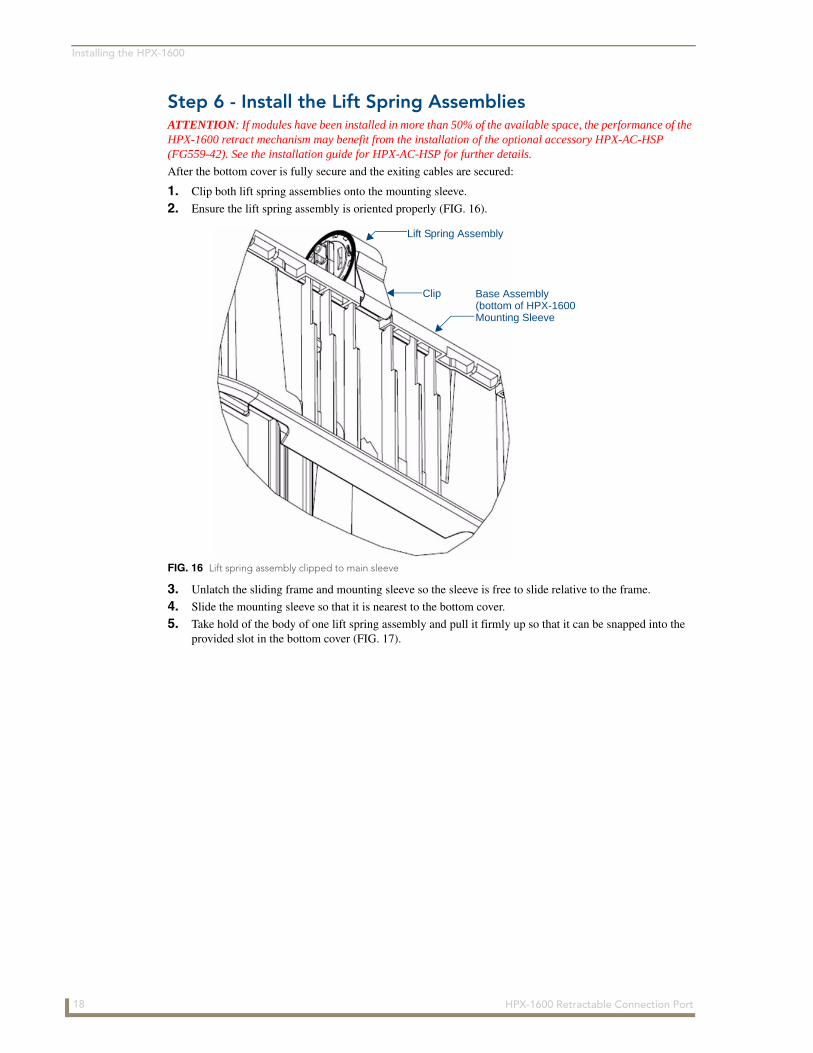
Step 6 - Install the Lift Spring AssembliesATTENTION: If modules have been installed in more than 50% of the available space, the performance of the HPX-1600 retract mechanism may benefit from the installation of the optional accessory HPX-AC-HSP (FG559-42). See the installation guide for HPX-AC-HSP for further details.
After the bottom cover is fully secure and the exiting cables are secured:
1. Clip both lift spring assemblies onto the mounting sleeve.
2. Ensure the lift spring assembly is oriented properly (FIG. 16).
3. Unlatch the sliding frame and mounting sleeve so the sleeve is free to slide relative to the frame.
4. Slide the mounting sleeve so that it is nearest to the bottom cover.
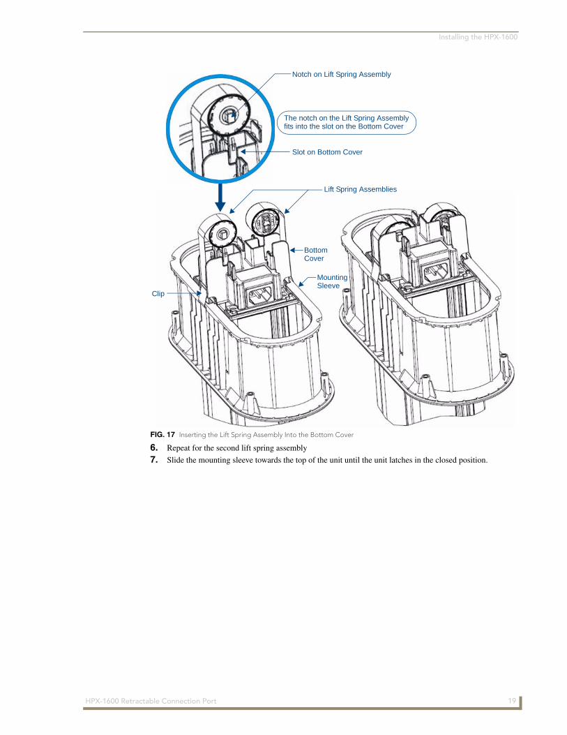
5. Take hold of the body of one lift spring assembly and pull it firmly up so that it can be snapped into the provided slot in the bottom cover (FIG. 17).
FIG. 16 Lift spring assembly clipped to main sleeve
Lift Spring Assembly
Clip
Mounting Sleeve(bottom of HPX-1600Base Assembly
18 HPX-1600 Retractable Connection Port
Installing the HPX-1600
6. Repeat for the second lift spring assembly
7. Slide the mounting sleeve towards the top of the unit until the unit latches in the closed position.
FIG. 17 Inserting the Lift Spring Assembly Into the Bottom Cover
The notch on the Lift Spring Assembly
Notch on Lift Spring Assembly
Slot on Bottom Cover
fits into the slot on the Bottom Cover
Lift Spring Assemblies
BottomCover
MountingSleeve
Clip
19HPX-1600 Retractable Connection Port
Installing the HPX-1600
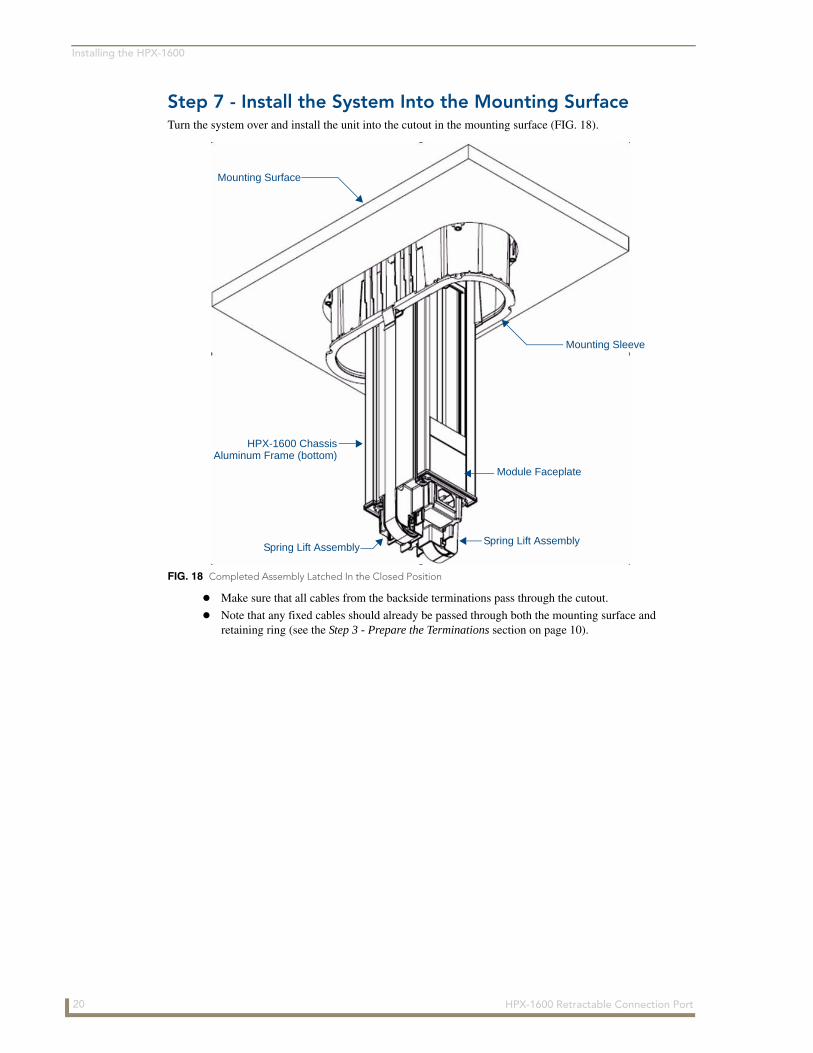
Step 7 - Install the System Into the Mounting SurfaceTurn the system over and install the unit into the cutout in the mounting surface (FIG. 18).
Make sure that all cables from the backside terminations pass through the cutout.
Note that any fixed cables should already be passed through both the mounting surface and retaining ring (see the Step 3 - Prepare the Terminations section on page 10).
FIG. 18 Completed Assembly Latched In the Closed Position
Mounting Surface
Mounting Sleeve
Spring Lift Assembly
HPX-1600 ChassisAluminum Frame (bottom)
Module Faceplate
Spring Lift Assembly
20 HPX-1600 Retractable Connection Port
Installing the HPX-1600
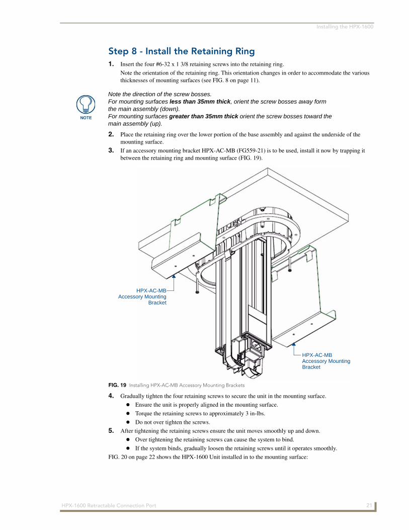
Step 8 - Install the Retaining Ring1. Insert the four #6-32 x 1 3/8 retaining screws into the retaining ring.
Note the orientation of the retaining ring. This orientation changes in order to accommodate the various thicknesses of mounting surfaces (see FIG. 8 on page 11).
2. Place the retaining ring over the lower portion of the base assembly and against the underside of the mounting surface.
3. If an accessory mounting bracket HPX-AC-MB (FG559-21) is to be used, install it now by trapping it between the retaining ring and mounting surface (FIG. 19).
4. Gradually tighten the four retaining screws to secure the unit in the mounting surface.
Ensure the unit is properly aligned in the mounting surface.
Torque the retaining screws to approximately 3 in-lbs.
Do not over tighten the screws.
5. After tightening the retaining screws ensure the unit moves smoothly up and down.
Over tightening the retaining screws can cause the system to bind.
If the system binds, gradually loosen the retaining screws until it operates smoothly.
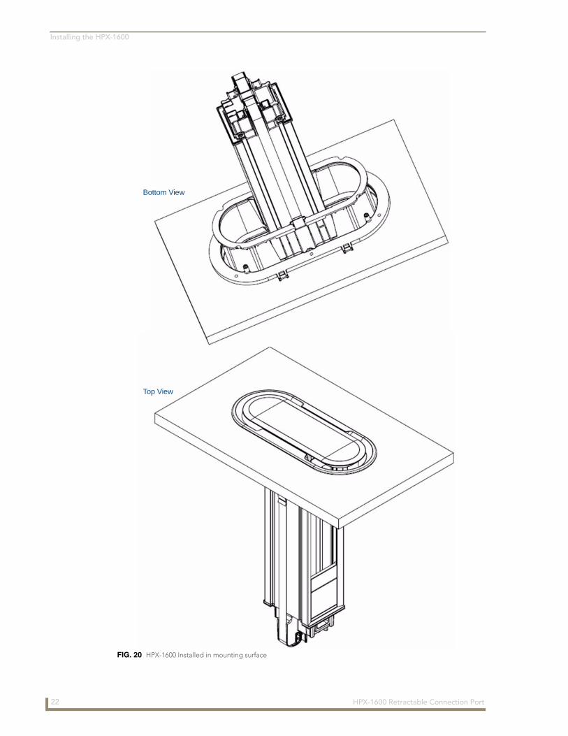
FIG. 20 on page 22 shows the HPX-1600 Unit installed in to the mounting surface:
Note the direction of the screw bosses. For mounting surfaces less than 35mm thick, orient the screw bosses away form the main assembly (down). For mounting surfaces greater than 35mm thick orient the screw bosses toward the main assembly (up).
FIG. 19 Installing HPX-AC-MB Accessory Mounting Brackets
HPX-AC-MBAccessory Mounting
Bracket
HPX-AC-MBAccessory MountingBracket
21HPX-1600 Retractable Connection Port
Installing the HPX-1600
FIG. 20 HPX-1600 Installed in mounting surface
Top View
Bottom View
22 HPX-1600 Retractable Connection Port
Installing the HPX-1600
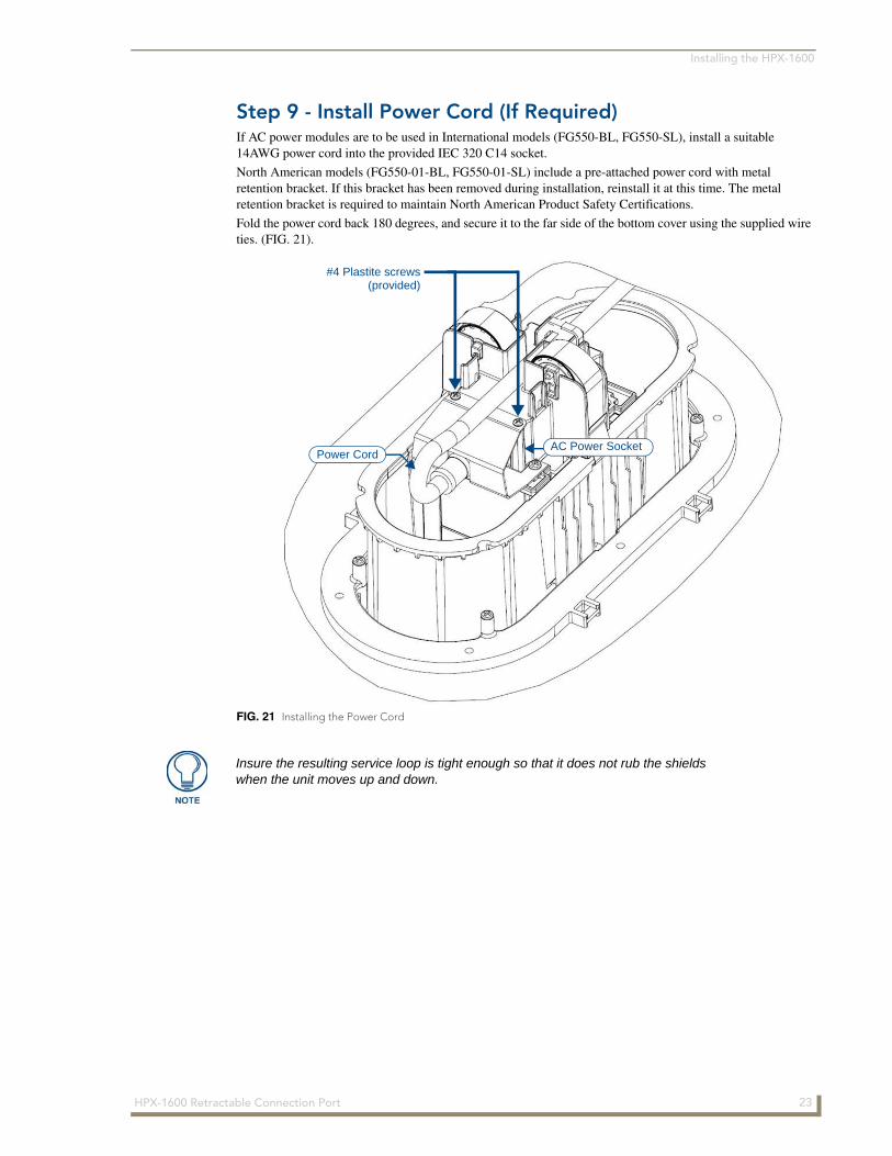
Step 9 - Install Power Cord (If Required)If AC power modules are to be used in International models (FG550-BL, FG550-SL), install a suitable 14AWG power cord into the provided IEC 320 C14 socket.
North American models (FG550-01-BL, FG550-01-SL) include a pre-attached power cord with metal retention bracket. If this bracket has been removed during installation, reinstall it at this time. The metal retention bracket is required to maintain North American Product Safety Certifications.
Fold the power cord back 180 degrees, and secure it to the far side of the bottom cover using the supplied wire ties. (FIG. 21).
FIG. 21 Installing the Power Cord
Power CordAC Power Socket
#4 Plastite screws(provided)
Insure the resulting service loop is tight enough so that it does not rub the shields when the unit moves up and down.
23HPX-1600 Retractable Connection Port

Installing the HPX-1600
Step 10 - Install Shields1. Secure the two shields to each other using the 8 supplied screws.
Ensure that any fixed cables pass through the assembled shield appropriately.
2. Snap the assembled shield onto the lower portion of the mounting sleeve.
3. Install the four additional mounting screws into the top of the shield to secure the shield to the mounting sleeve (FIG. 22).
FIG. 22 Installing the Shields
Shields
4 screws secure the topof the Shields to the
Mounting Sleeve
8 screws (4 on each side)secure the two Shields to
each other
24 HPX-1600 Retractable Connection Port

Installing the HPX-1600
Step 11 - Secure CablesTerminate the backside connections as required for each cable exiting bottom of the HPX-1600.
Secure these cables and the power cable to the four tabs provided on the retaining ring using the supplied wire ties (FIG. 23).
Ensure there is sufficient service loop to allow the system to travel in its full range of motion.
Avoid excess service loop as this can place significant weight on the sliding and lifting mechanism and prevent the system from functioning properly.
Ensure the service loop does not catch on the shields or any other obstruction and is away from users who might kick or snag the cables.
Secure the cables in at least one additional location after they have been secured to the retaining ring so as to prevent undue stress on the system if the cables are inadvertently kicked, snagged or pulled.
FIG. 23 Secured Service Loop
Retaining Ring
Shields
Mounting Surface
Tabs/Wire Ties (2 on each side)
Cables from bottomof HPX-1600
25HPX-1600 Retractable Connection Port

Installing the HPX-1600
26 HPX-1600 Retractable Connection Port
HPX-P200-xx Power Outlet Module
HPX-P200-xx Power Outlet Module
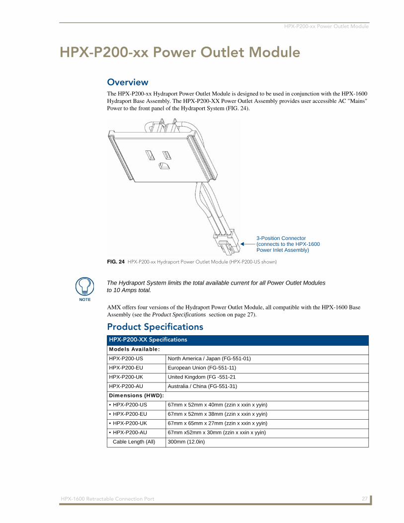
OverviewThe HPX-P200-xx Hydraport Power Outlet Module is designed to be used in conjunction with the HPX-1600 Hydraport Base Assembly. The HPX-P200-XX Power Outlet Assembly provides user accessible AC "Mains" Power to the front panel of the Hydraport System (FIG. 24).
AMX offers four versions of the Hydraport Power Outlet Module, all compatible with the HPX-1600 Base Assembly (see the Product Specifications section on page 27).
Product Specifications
FIG. 24 HPX-P200-xx Hydraport Power Outlet Module (HPX-P200-US shown)
3-Position Connector(connects to the HPX-1600Power Inlet Assembly)
The Hydraport System limits the total available current for all Power Outlet Modules to 10 Amps total.
HPX-P200-XX Specifications
Models Available:
HPX-P200-US North America / Japan (FG-551-01)
HPX-P200-EU European Union (FG-551-11)
HPX-P200-UK United Kingdom (FG -551-21
HPX-P200-AU Australia / China (FG-551-31)
Dimensions (HWD):
• HPX-P200-US 67mm x 52mm x 40mm (zzin x xxin x yyin)
• HPX-P200-EU 67mm x 52mm x 38mm (zzin x xxin x yyin)
• HPX-P200-UK 67mm x 65mm x 27mm (zzin x xxin x yyin)
• HPX-P200-AU 67mm x52mm x 30mm (zzin x xxin x yyin)
Cable Length (All) 300mm (12.0in)
27HPX-1600 Retractable Connection Port
HPX-P200-xx Power Outlet Module
Installing the HPX-P200-XX Power Outlet ModuleDisconnect the IEC C-14 Power Inlet Connector On the Hydraport Base Assembly
HPX-P200-XX Specifications (Cont.)
Weight:
• HPX-P200-US 60g (2.12 oz.)
• HPX-P200-EU 69g (2.43 oz.)
• HPX-P200-UK 74g (2.61 oz.)
• HPX-P200-AU 60g (2.12 oz.)
Enclosure: Matt black finished face plate (Polycarbonate plastic).
Rear Connections: Three position plug-in connector for use with HPX-1600 Hydraport Base Assembly.
Compatibility: • HPX-1600 Hydraport Base Assembly
• HPX-PAK-US, Hydraport Power Accessory Kit w/ US power cord (FG559-31)
• HPX-PAK-I, Hydraport Power Accessory Kit w/ no power cord (FG559-32)
Included Accessories: Quick start guide
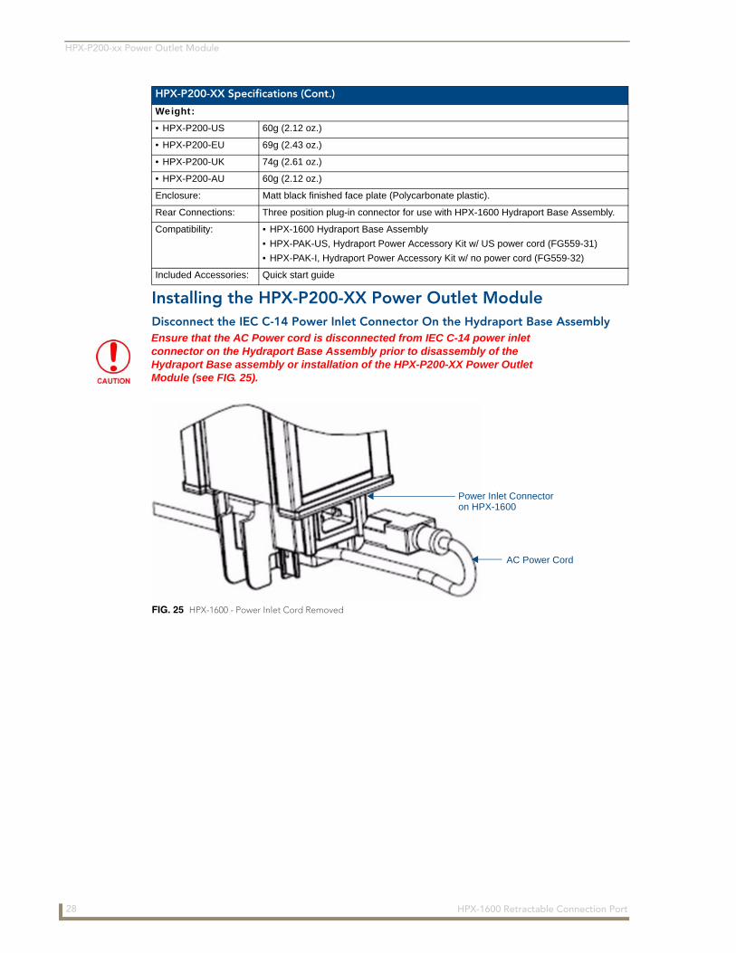
Ensure that the AC Power cord is disconnected from IEC C-14 power inlet connector on the Hydraport Base Assembly prior to disassembly of the Hydraport Base assembly or installation of the HPX-P200-XX Power Outlet Module (see FIG. 25).
FIG. 25 HPX-1600 - Power Inlet Cord Removed
AC Power Cord
Power Inlet Connectoron HPX-1600
28 HPX-1600 Retractable Connection Port
HPX-P200-xx Power Outlet Module
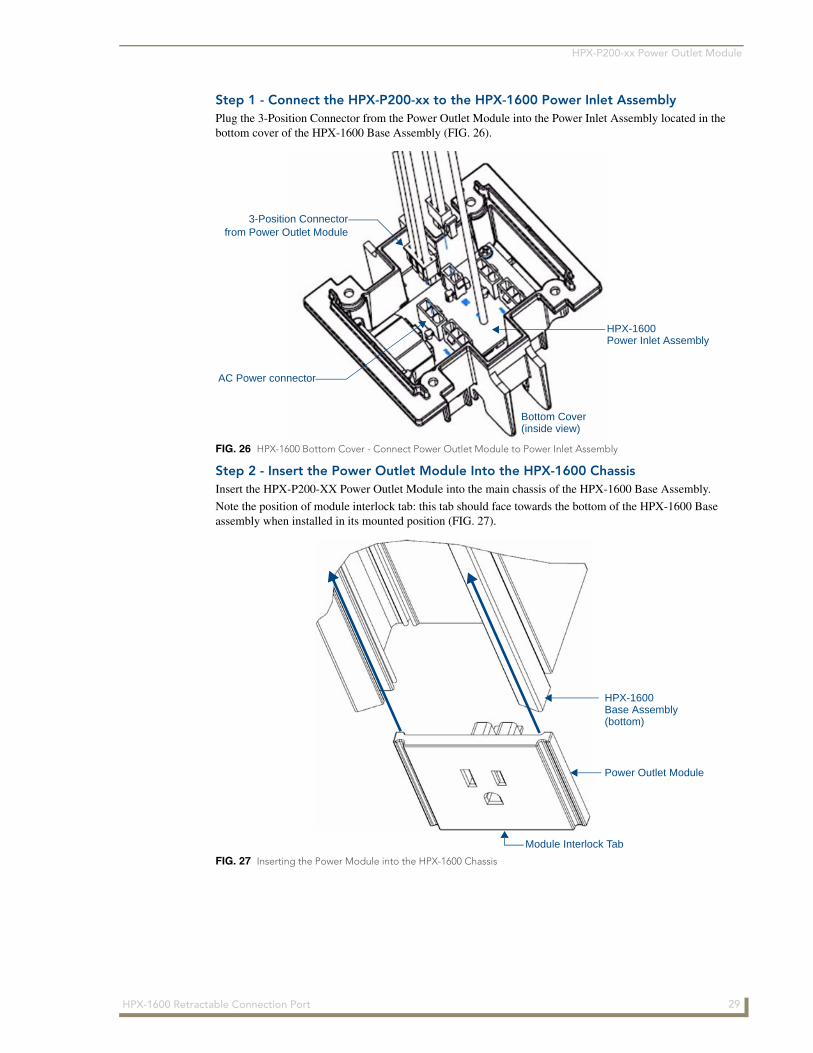
Step 1 - Connect the HPX-P200-xx to the HPX-1600 Power Inlet AssemblyPlug the 3-Position Connector from the Power Outlet Module into the Power Inlet Assembly located in the bottom cover of the HPX-1600 Base Assembly (FIG. 26).
Step 2 - Insert the Power Outlet Module Into the HPX-1600 ChassisInsert the HPX-P200-XX Power Outlet Module into the main chassis of the HPX-1600 Base Assembly.
Note the position of module interlock tab: this tab should face towards the bottom of the HPX-1600 Base assembly when installed in its mounted position (FIG. 27).
FIG. 26 HPX-1600 Bottom Cover - Connect Power Outlet Module to Power Inlet Assembly
FIG. 27 Inserting the Power Module into the HPX-1600 Chassis
Bottom Cover(inside view)
AC Power connector
3-Position Connectorfrom Power Outlet Module
HPX-1600Power Inlet Assembly
Power Outlet Module
HPX-1600 Base Assembly(bottom)
Module Interlock Tab
29HPX-1600 Retractable Connection Port
HPX-P200-xx Power Outlet Module
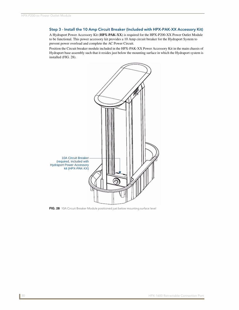
Step 3 - Install the 10 Amp Circuit Breaker (Included with HPX-PAK-XX Accessory Kit) A Hydraport Power Accessory Kit (HPX-PAK-XX) is required for the HPX-P200-XX Power Outlet Module to be functional. This power accessory kit provides a 10 Amp circuit breaker for the Hydraport System to prevent power overload and complete the AC Power Circuit.
Position the Circuit breaker module included in the HPX-PAK-XX Power Accessory Kit in the main chassis of Hydraport base assembly such that it resides just below the mounting surface in which the Hydraport system is installed (FIG. 28).
FIG. 28 10A Circuit Breaker Module positioned just below mounting surface level
10A Circuit Breaker(required, included with
Hydraport Power Accessorykit (HPX-PAK-XX)
30 HPX-1600 Retractable Connection Port
HPX-PA-HVI High Voltage Isolator
HPX-PA-HVI High Voltage Isolator
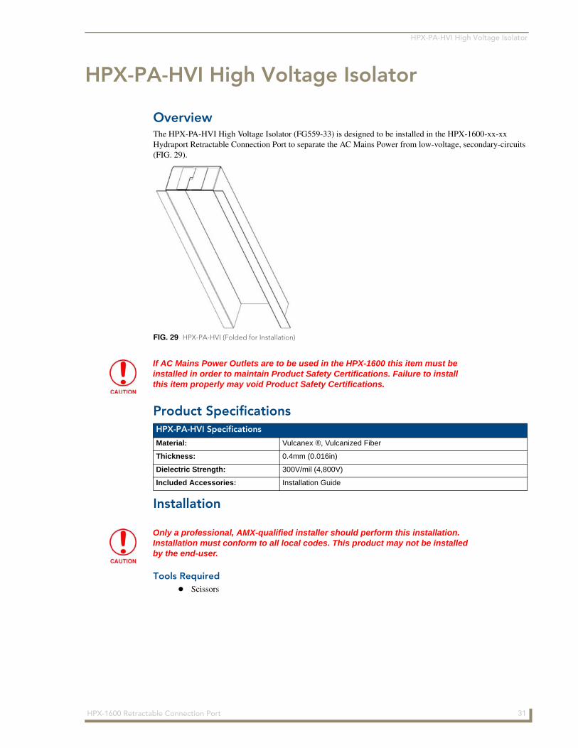
OverviewThe HPX-PA-HVI High Voltage Isolator (FG559-33) is designed to be installed in the HPX-1600-xx-xx Hydraport Retractable Connection Port to separate the AC Mains Power from low-voltage, secondary-circuits (FIG. 29).
Product Specifications
Installation
Tools RequiredScissors
FIG. 29 HPX-PA-HVI (Folded for Installation)
If AC Mains Power Outlets are to be used in the HPX-1600 this item must be installed in order to maintain Product Safety Certifications. Failure to install this item properly may void Product Safety Certifications.
HPX-PA-HVI Specifications
Material: Vulcanex ®, Vulcanized Fiber
Thickness: 0.4mm (0.016in)
Dielectric Strength: 300V/mil (4,800V)
Included Accessories: Installation Guide
Only a professional, AMX-qualified installer should perform this installation. Installation must conform to all local codes. This product may not be installed by the end-user.
31HPX-1600 Retractable Connection Port
HPX-PA-HVI High Voltage Isolator
Step 1 - Install Low-Voltage Secondary Circuit Modules
Install all low-voltage, secondary-circuit modules into the HPX-1600 Hydraport Base Assembly from the bottom of the unit according to the instructions supplied with the HPX-1600 and or low-voltage, secondary-circuit modules. For more information refer to the HPX-1600 Operation Reference Guide.
Position the cables coming from the low-voltage, secondary-circuit modules along the sides of the aluminum chassis. These cables will pass along the outside of the folded High Voltage Isolator and exit the unit through the square openings in the bottom cover.
Step 2 - Fold the High Voltage IsolatorUse the score lines on the High Voltage Isolator to fold the paper into the shape shown in Figure 1. Interlock the two tabs and slots at the top of the part with the square tab (back) folded inside the interlocking tabs (sides).
Pre-crease the folds as required to achieve a sharp, square fold.
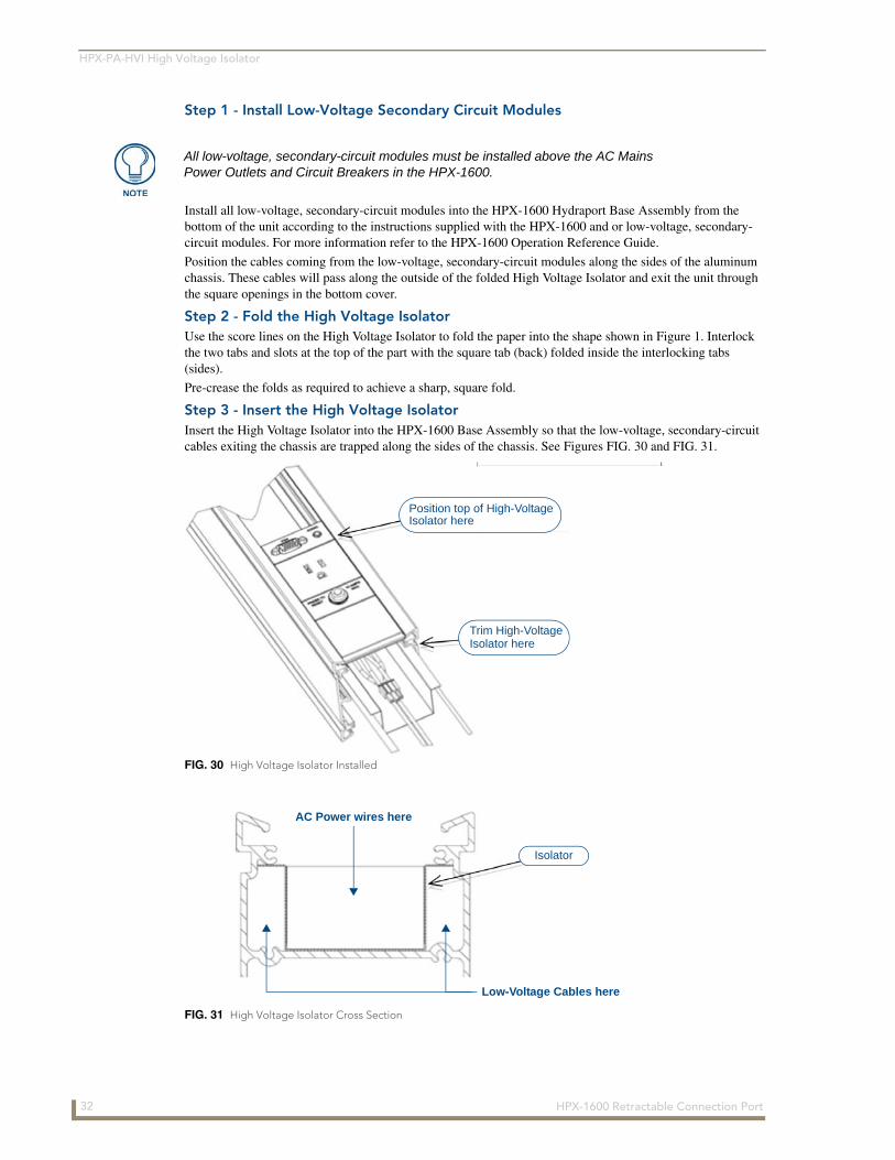
Step 3 - Insert the High Voltage IsolatorInsert the High Voltage Isolator into the HPX-1600 Base Assembly so that the low-voltage, secondary-circuit cables exiting the chassis are trapped along the sides of the chassis. See Figures FIG. 30 and FIG. 31.
All low-voltage, secondary-circuit modules must be installed above the AC Mains Power Outlets and Circuit Breakers in the HPX-1600.
FIG. 30 High Voltage Isolator Installed
FIG. 31 High Voltage Isolator Cross Section
Trim High-Voltage Isolator here
Position top of High-VoltageIsolator here
Isolator
AC Power wires here
Low-Voltage Cables here
32 HPX-1600 Retractable Connection Port
HPX-PA-HVI High Voltage Isolator
Step 4 - Mark and Trim High Voltage Isolator
1. Position the High Voltage Isolator so that the partition created by the top folded tabs falls between the last low-voltage, secondary-circuit module and the first AC Mains Power Outlet.
2. Mark the High Voltage Isolator at the point it exits the aluminum chassis.
3. Remove the High Voltage Isolator and trim the paper so that it will be flush with the bottom of the chassis upon final installation.
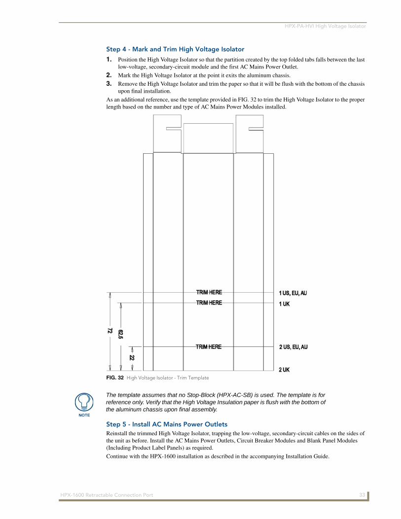
As an additional reference, use the template provided in FIG. 32 to trim the High Voltage Isolator to the proper length based on the number and type of AC Mains Power Modules installed.
Step 5 - Install AC Mains Power OutletsReinstall the trimmed High Voltage Isolator, trapping the low-voltage, secondary-circuit cables on the sides of the unit as before. Install the AC Mains Power Outlets, Circuit Breaker Modules and Blank Panel Modules (Including Product Label Panels) as required.
Continue with the HPX-1600 installation as described in the accompanying Installation Guide.
FIG. 32 High Voltage Isolator - Trim Template
The template assumes that no Stop-Block (HPX-AC-SB) is used. The template is for reference only. Verify that the High Voltage Insulation paper is flush with the bottom of the aluminum chassis upon final assembly.
33HPX-1600 Retractable Connection Port
4/12
©20
12 A
MX
. All
right
s re
serv
ed. A
MX
and
the
AM
X lo
go
are
reg
iste
red
tra
dem
arks
of A
MX
. AM
X r
eser
ves
the
rig
ht t
o a
lter
spec
ifica
tions
with
out
no
tice
at a
ny t
ime.
3000 RESEARCH DRIVE, RICHARDSON, TX 75082 USA • 800.222.0193 • 469.624.8000 • 469-624-7153 fax • 800.932.6993 technical support • www.amx.com
Increase Your Revenuethrough education + knowledge
In the ever-changing AV industry, continual education is key to success. AMX University is dedicated to ensuring that you have the opportunity to gather the information and experience you need to deliver strong AMX solutions. Plus, AMX courses also help you earn CEDIA, NSCA, InfoComm, and AMX continuing education units (CEUs).
Visit AMX University online for 24/7/365 access to:- Schedules and registration for any AMX University course- Travel and hotel information- Your individual certification requirements and progress