Embed Size (px)
Citation preview
Installation of a Monitoring Well Cluster at the S-356 Pump Station
Technical Publication WS-45 February 2018
Keith Smith, P.G. Natalie Kraft, Technical Editor
Resource Evaluation Section, Water Supply Bureau
South Florida Water Management District | 3301 Gun Club Road | West Palm Beach, FL 33406
ii
ACKNOWLEDGMENTS
Sean Sculley of the South Florida Water Management District was the overall project manager and contact between the District, the National Park Service, and the United States Army Corps of Engineers. Mike Wacker of the United States Geological Survey was the drilling site manager and conducted the geophysical logging. Brian McCord of GFA International was the driller on this project.
EXECUTIVE SUMMARY
In June 2015, the South Florida Water Management District (SFWMD or District), in cooperation with the U.S. Geological Survey, installed a four-well monitoring well cluster at the S-356 pump station in Miami-Dade County, Florida. This work was performed as part of a Cooperative Agreement between the SFWMD, the United States Department of the Interior, the United States Army Corps of Engineers, and the National Park Service. The wells were installed to support a test of the S-356 pump station to determine if the pumps can effectively move water into Everglades National Park, and the impacts of operating the pumps for this purpose. Monitoring wells were installed in three producing zones with the Biscayne aquifer, and an additional monitoring well was installed in the top of the Tamiami formation. Initial water quality sampling of the four wells was conducted in July 2015. Water levels initially were collected by temporary data loggers. Permanent data loggers and telemetry equipment were installed to allow real-time monitoring. Data collected from this well cluster and other monitor wells in the area will help determine impacts from groundwater flows (quantity and quality) during operation of the pump station.
iii
TABLE OF CONTENTS Introduction ................................................................................................................................................... 1
Site Description ............................................................................................................................................. 1
Pilot Hole Coring .......................................................................................................................................... 4
Geophysical Logging .................................................................................................................................... 5
Monitoring Well Installation ......................................................................................................................... 5
Temporary Installation of Data Loggers ....................................................................................................... 7
Installation of Telemetry Equipment ............................................................................................................ 7
Water Quality Sampling ............................................................................................................................... 9
Summary ....................................................................................................................................................... 9
Appendix A Statement of Work for USGS to Provide Logging and Site Supervision ............................. A-1
Appendix B Statement of Work for Installation of Monitor Wells........................................................... B-1
Appendix C Preliminary (Draft) Plot of the Geophysical Logs ................................................................ C-1
Appendix D Initial Water Quality Data .................................................................................................... D-1
LIST OF TABLES Table 1. Field observations of core samples from the S-356 pilot hole. ................................................. 5 Table 2. Monitoring well information. .................................................................................................... 5
LIST OF FIGURES Figure 1. Location of the S-356 pump station in Miami-Dade County, Florida. ..................................... 2 Figure 2. Location of the S-356 pump station monitor well cluster. ........................................................ 3 Figure 3. A typical field photograph of a core sample obtained from the pilot hole. ............................... 4 Figure 4. Completed wellheads (photo looking east-southeast). .............................................................. 6 Figure 5. Completed monitor well. ........................................................................................................... 6 Figure 6. Water elevation hydrographs. ................................................................................................... 7 Figure 7. Site with telemetry equipment installed. ................................................................................... 8 Figure 8. Close-up photograph of site with telemetry equipment installed. ............................................. 8
ACRONYMS AND ABBREVIATIONS bls below land surface
District South Florida Water Management District
NAVD88 North American Vertical Datum of 1988
NPS National Park Service
OBI optical borehole imagery
PVC polyvinyl chloride
SFWMD South Florida Water Management District
USGS United States Geological Survey
1
INTRODUCTION
The South Florida Water Management District (SFWMD or District), in cooperation with the United States Geological Survey (USGS), installed a four-well monitoring well cluster at the S-356 pump station in June 2015. The District provided the funding and overall project management, while the USGS provided the geophysical logging and site management during drilling, logging, and well installation. Much of the information in this report was included in the USGS’s preliminary data report. A copy of the statement of work for the USGS is provided as Appendix A.
This work was performed as part of a Cooperative Agreement between the SFWMD and the United States Department of the Interior, the United States Army Corps of Engineers, and the National Park Service (NPS) — “S356 Pump Station Groundwater Well Cluster Installation, Geophysical Logging, and Instrumentation”. The NPS agreed to reimburse the SFWMD for these services under this Cooperative Agreement.
The wells were installed to support a test of the S-356 pump station to determine if the pumps can effectively move water into Everglades National Park, and the impacts of operating the pumps for this purpose. A copy of the statement of work for the coring and well installation is included in Appendix B. Continuous cores and geophysical logs were obtained from a pilot hole to a depth of 61 feet through the Biscayne aquifer into the top of the Tamiami formation. Three producing zones in the Biscayne aquifer were identified based on data collected from the pilot hole. Monitoring wells were installed in each producing zone, and an additional monitoring well was installed in the top of the Tamiami formation. Initial water quality sampling of the four wells was conducted in July 2015, and data loggers were temporarily installed in each well. The wells were surveyed to establish reference elevations, and permanent telemetry equipment was installed to allow remote real-time water level monitoring. Data collected from this well cluster and other monitor wells in the area will help determine impacts from groundwater flows (quantity and quality) during operation of the pump station.
SITE DESCRIPTION
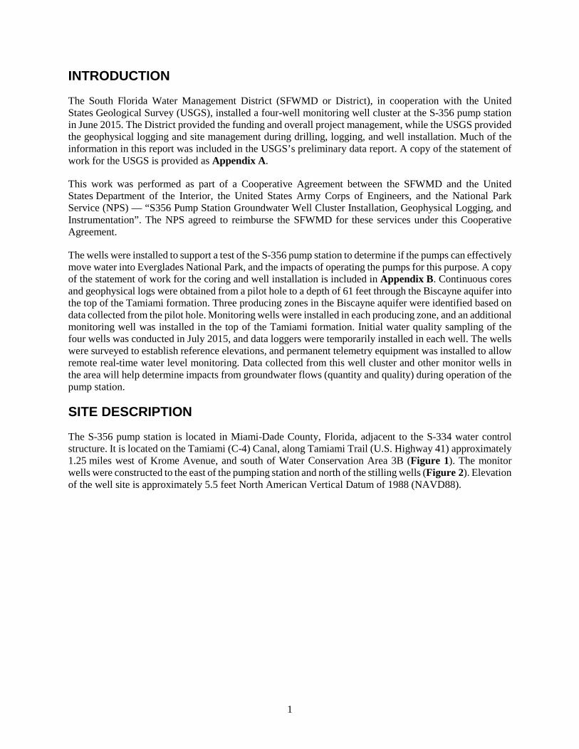
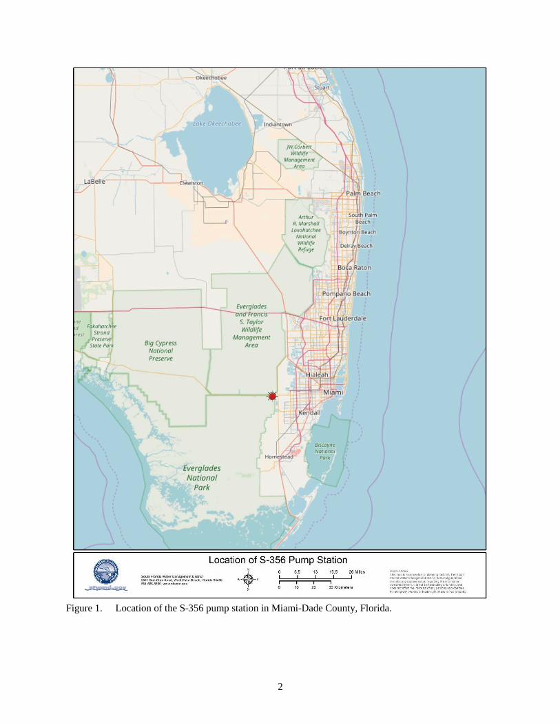
The S-356 pump station is located in Miami-Dade County, Florida, adjacent to the S-334 water control structure. It is located on the Tamiami (C-4) Canal, along Tamiami Trail (U.S. Highway 41) approximately 1.25 miles west of Krome Avenue, and south of Water Conservation Area 3B (Figure 1). The monitor wells were constructed to the east of the pumping station and north of the stilling wells (Figure 2). Elevation of the well site is approximately 5.5 feet North American Vertical Datum of 1988 (NAVD88).
2
Figure 1. Location of the S-356 pump station in Miami-Dade County, Florida.
3
Figure 2. Location of the S-356 pump station monitor well cluster.
4
PILOT HOLE CORING
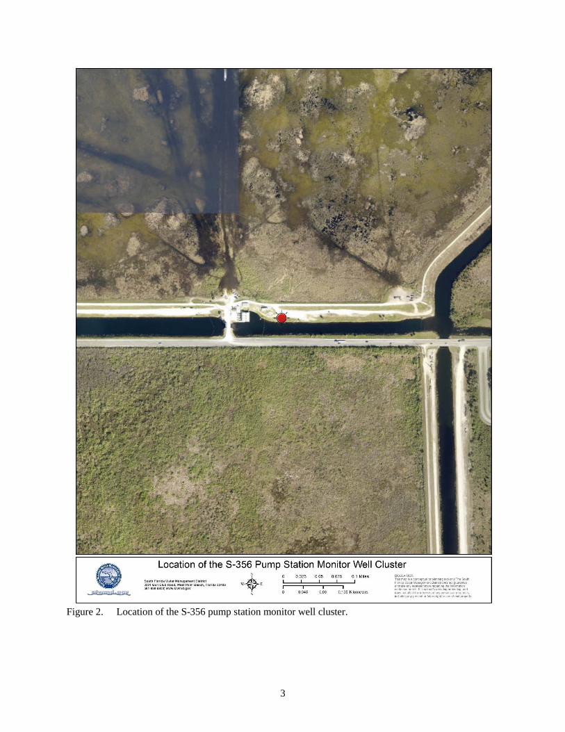
The pilot hole was constructed on June 15, 2015. Surface casing was installed to a depth of 6.75 feet below land surface (bls) to stabilize drilling operations. Continuous cores were obtained from the bottom of the surface casing to a depth of approximately 51 feet bls, below which no samples were recovered. The core barrel was advanced for another 10 feet, and approximately 1.5 feet of sand and shells were recovered, indicating that the Tamiami formation had been encountered. Additional cores were obtained from an adjacent pilot hole from land surface to approximately 12.5 feet bls because the first pilot hole missed this depth interval due to installation of the surface casing. The cores were marked for orientation, photographed, boxed, and are stored at the USGS Caribbean-Florida Water Science Center in Davie, Florida. The deeper pilot hole was developed by air lifting to prepare it for geophysical logging. Figure 3 shows a typical section of the core. Both core holes were converted into monitoring wells. Field observations of the composite cores are summarized in Table 1.
Figure 3. A typical field photograph of a core sample obtained from the pilot hole.
5
Table 1. Field observations of core samples from the S-356 pilot hole.
Depth (feet bls) Description 0-11 Highly solutioned limestone 11-13 Granular limestone 13-27 Limestone (alternating consolidated and rubble layers) 27-30 Limestone 30-31 Limestone (rubble) 31-40 Limestone (alternating consolidated and rubble layers) 40-51 Limestone, slight color shift (tan to gray) at approximately 46 feet 51-61 Sand and shell
bls = below land surface.
GEOPHYSICAL LOGGING
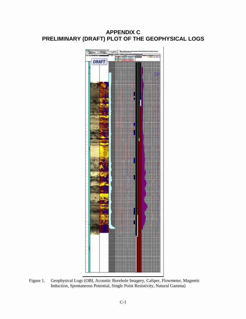
Geophysical logging was conducted on June 17, 2015. Logs included optical borehole imaging (OBI), acoustic borehole imaging, caliper, flowmeter (spinner), magnetic induction, spontaneous potential, single point resistance, and natural gamma ray. The OBI log indicated that the bottom of the Biscayne aquifer (contact between limestone and sand/shell layer) occurred at 51.4 feet bls. The acoustic borehole image provided information on borehole density and rugosity. During flowmeter logging, the pilot hole was pumped at approximately 120 gallons per minute, and the flowmeter tool was run up and down the pilot hole at speeds of 10 and 20 feet per minute. All geophysical data were plotted, displayed, and used to identify producing zones within the Biscayne aquifer. Three producing zones were identified at depths of approximately 12, 24, and 48 feet bls. Producing zones at depths less than 9 feet bls could not be determined using the flowmeter logs due to interference from the suction pipe. Preliminary (draft) copies of the logs are provided in Appendix C.
MONITORING WELL INSTALLATION
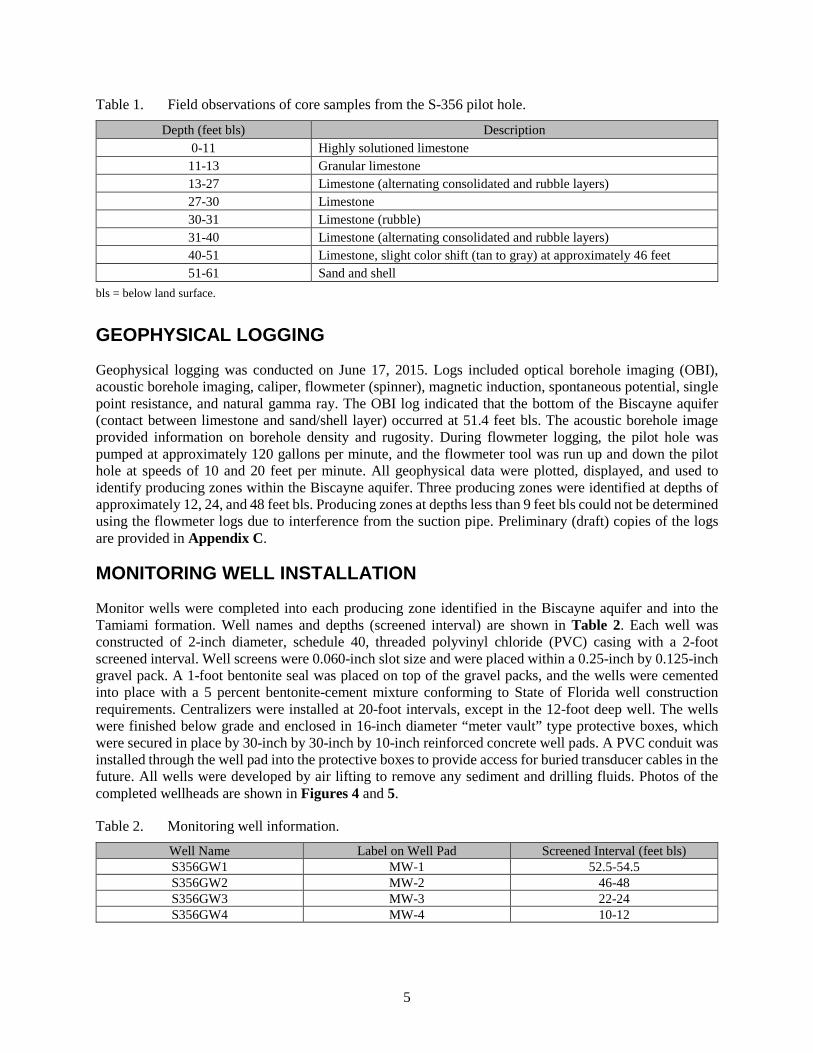
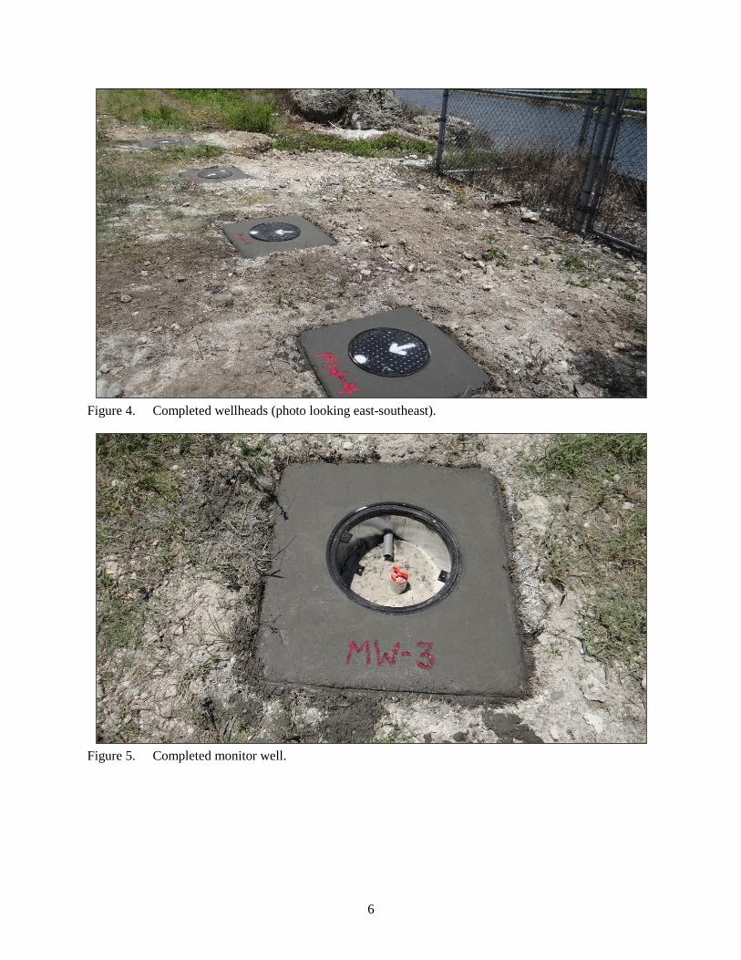
Monitor wells were completed into each producing zone identified in the Biscayne aquifer and into the Tamiami formation. Well names and depths (screened interval) are shown in Table 2. Each well was constructed of 2-inch diameter, schedule 40, threaded polyvinyl chloride (PVC) casing with a 2-foot screened interval. Well screens were 0.060-inch slot size and were placed within a 0.25-inch by 0.125-inch gravel pack. A 1-foot bentonite seal was placed on top of the gravel packs, and the wells were cemented into place with a 5 percent bentonite-cement mixture conforming to State of Florida well construction requirements. Centralizers were installed at 20-foot intervals, except in the 12-foot deep well. The wells were finished below grade and enclosed in 16-inch diameter “meter vault” type protective boxes, which were secured in place by 30-inch by 30-inch by 10-inch reinforced concrete well pads. A PVC conduit was installed through the well pad into the protective boxes to provide access for buried transducer cables in the future. All wells were developed by air lifting to remove any sediment and drilling fluids. Photos of the completed wellheads are shown in Figures 4 and 5.
Table 2. Monitoring well information.
Well Name Label on Well Pad Screened Interval (feet bls) S356GW1 MW-1 52.5-54.5 S356GW2 MW-2 46-48 S356GW3 MW-3 22-24 S356GW4 MW-4 10-12
6
Figure 4. Completed wellheads (photo looking east-southeast).
Figure 5. Completed monitor well.
7
TEMPORARY INSTALLATION OF DATA LOGGERS
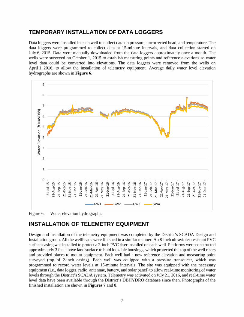
Data loggers were installed in each well to collect data on pressure, uncorrected head, and temperature. The data loggers were programmed to collect data at 15-minute intervals, and data collection started on July 6, 2015. Data were manually downloaded from the data loggers approximately once a month. The wells were surveyed on October 1, 2015 to establish measuring points and reference elevations so water level data could be converted into elevations. The data loggers were removed from the wells on April 1, 2016, to allow the installation of telemetry equipment. Average daily water level elevation hydrographs are shown in Figure 6.
Figure 6. Water elevation hydrographs.
INSTALLATION OF TELEMETRY EQUIPMENT
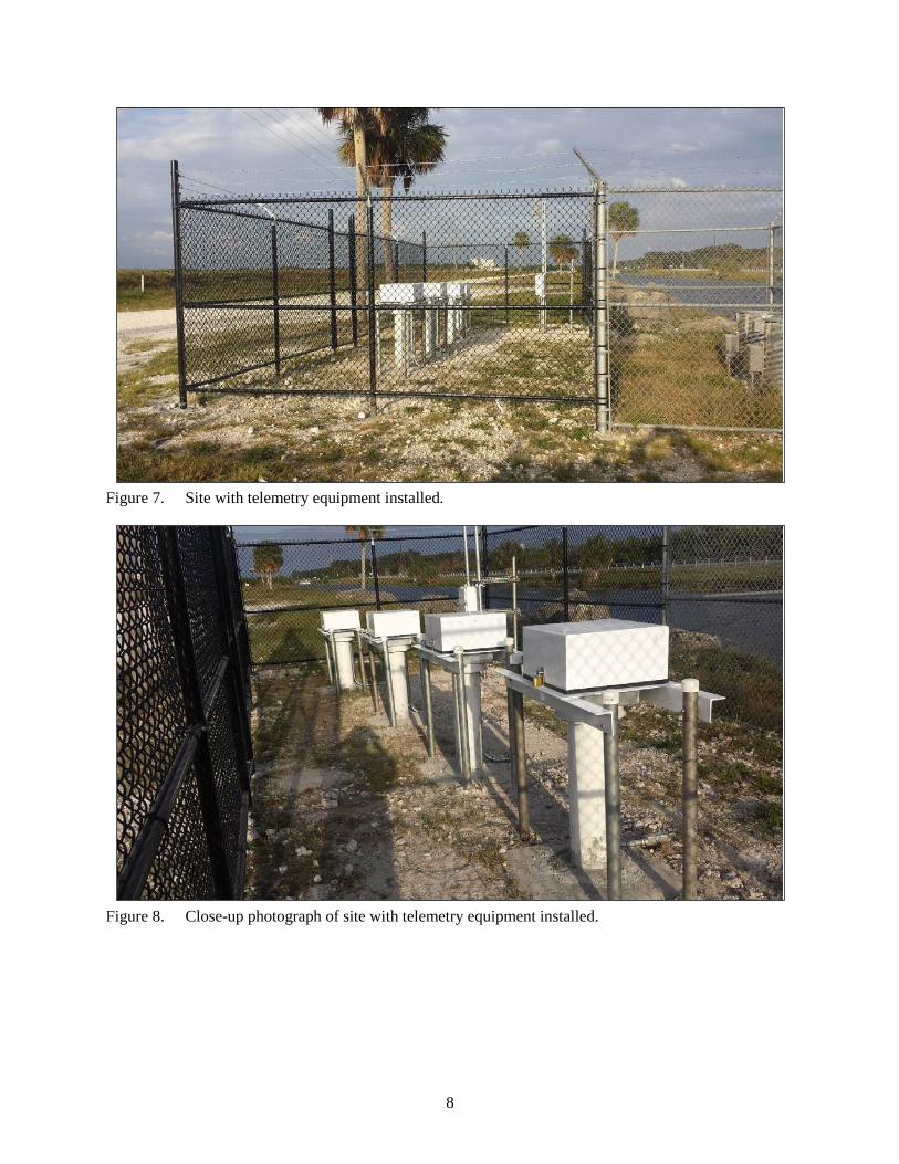
Design and installation of the telemetry equipment was completed by the District’s SCADA Design and Installation group. All the wellheads were finished in a similar manner. An 8-inch ultraviolet-resistant PVC surface casing was installed to protect a 2-inch PVC riser installed on each well. Platforms were constructed approximately 3 feet above land surface to hold lockable housings, which protected the top of the well risers and provided places to mount equipment. Each well had a new reference elevation and measuring point surveyed (top of 2-inch casing). Each well was equipped with a pressure transducer, which was programmed to record water levels at 15-minute intervals. The site was equipped with the necessary equipment (i.e., data logger, radio, antennae, battery, and solar panel) to allow real-time monitoring of water levels through the District’s SCADA system. Telemetry was activated on July 21, 2016, and real-time water level data have been available through the District’s DBHYDRO database since then. Photographs of the finished installation are shown in Figures 7 and 8.
0
1
2
3
4
5
6
7
8
9
21-Ju
l-15
21-A
ug-1
521
-Sep
-15
21-O
ct-1
521
-Nov
-15
21-D
ec-1
521
-Jan-
1621
-Feb
-16
21-M
ar-1
621
-Apr
-16
21-M
ay-1
621
-Jun-
1621
-Jul-1
621
-Aug
-16
21-S
ep-1
621
-Oct
-16
21-N
ov-1
621
-Dec
-16
21-Ja
n-17
21-F
eb-1
721
-Mar
-17
21-A
pr-1
721
-May
-17
21-Ju
n-17
21-Ju
l-17
21-A
ug-1
721
-Sep
-17
21-O
ct-1
721
-Nov
-17
21-D
ec-1
7
Wat
er E
leva
tion
(ft N
AVD8
8)
GW1 GW2 GW3 GW4
8
Figure 7. Site with telemetry equipment installed.
Figure 8. Close-up photograph of site with telemetry equipment installed.
9
WATER QUALITY SAMPLING
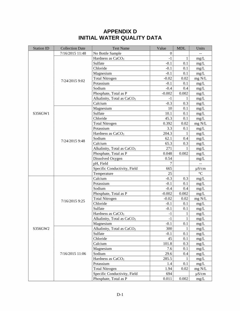
Initial water quality sampling of the wells was conducted by the District on July 16 and 24, 2015. The initial sampling was done over 2 days due to weather conditions (rain) halting sampling on the first day. The initial sampling provides a baseline for additional sampling that will be conducted as part of the upcoming S-356 pump station test. Sampled parameters included pH, temperature, conductivity, hardness, alkalinity, dissolved oxygen, potassium, sodium, calcium, magnesium, sulfate, chloride, and total phosphorus. Preliminary water quality data are included in Appendix D.
SUMMARY
In June 2015, The SFWMD, in cooperation with the USGS, installed a four-well monitoring well cluster at the S-356 pump station in Miami-Dade County, Florida. The wells were installed to support a test of the S-356 pump station to determine if the pumps can effectively move water into Everglades National Park, and the impacts of operating the pumps for this purpose. Continuous cores and geophysical logs were obtained from a pilot hole to a depth of 61 feet through the Biscayne aquifer into the top of the Tamiami formation. Three producing zones in the Biscayne aquifer were identified based on data collected from the pilot hole. Monitoring wells were installed in each producing zone, and an additional monitoring well was installed in the top of the Tamiami formation. Initial water quality sampling of the four wells was conducted in July 2015, and data loggers were temporarily installed in each well. The wells were surveyed to establish reference elevations, and permanent telemetry equipment was installed to allow remote real-time water level monitoring. Water level and water quality data collected from this well cluster and other monitor wells in the area will help determine impacts from groundwater flows (quantity and quality) during operation of the pump station.
A-1
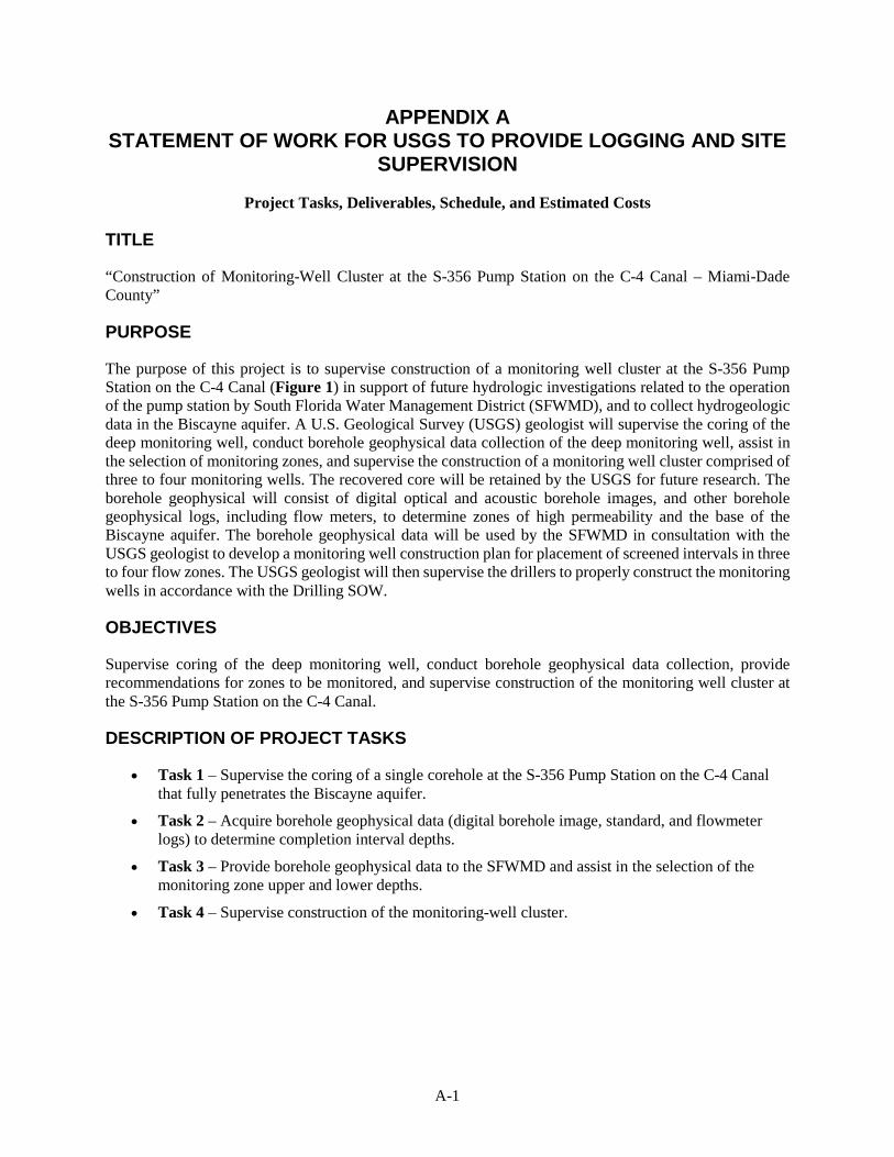
APPENDIX A STATEMENT OF WORK FOR USGS TO PROVIDE LOGGING AND SITE
SUPERVISION
Project Tasks, Deliverables, Schedule, and Estimated Costs
TITLE
“Construction of Monitoring-Well Cluster at the S-356 Pump Station on the C-4 Canal – Miami-Dade County”
PURPOSE
The purpose of this project is to supervise construction of a monitoring well cluster at the S-356 Pump Station on the C-4 Canal (Figure 1) in support of future hydrologic investigations related to the operation of the pump station by South Florida Water Management District (SFWMD), and to collect hydrogeologic data in the Biscayne aquifer. A U.S. Geological Survey (USGS) geologist will supervise the coring of the deep monitoring well, conduct borehole geophysical data collection of the deep monitoring well, assist in the selection of monitoring zones, and supervise the construction of a monitoring well cluster comprised of three to four monitoring wells. The recovered core will be retained by the USGS for future research. The borehole geophysical will consist of digital optical and acoustic borehole images, and other borehole geophysical logs, including flow meters, to determine zones of high permeability and the base of the Biscayne aquifer. The borehole geophysical data will be used by the SFWMD in consultation with the USGS geologist to develop a monitoring well construction plan for placement of screened intervals in three to four flow zones. The USGS geologist will then supervise the drillers to properly construct the monitoring wells in accordance with the Drilling SOW.
OBJECTIVES
Supervise coring of the deep monitoring well, conduct borehole geophysical data collection, provide recommendations for zones to be monitored, and supervise construction of the monitoring well cluster at the S-356 Pump Station on the C-4 Canal.
DESCRIPTION OF PROJECT TASKS
• Task 1 – Supervise the coring of a single corehole at the S-356 Pump Station on the C-4 Canal that fully penetrates the Biscayne aquifer.
• Task 2 – Acquire borehole geophysical data (digital borehole image, standard, and flowmeter logs) to determine completion interval depths.
• Task 3 – Provide borehole geophysical data to the SFWMD and assist in the selection of the monitoring zone upper and lower depths.
• Task 4 – Supervise construction of the monitoring-well cluster.
A-2
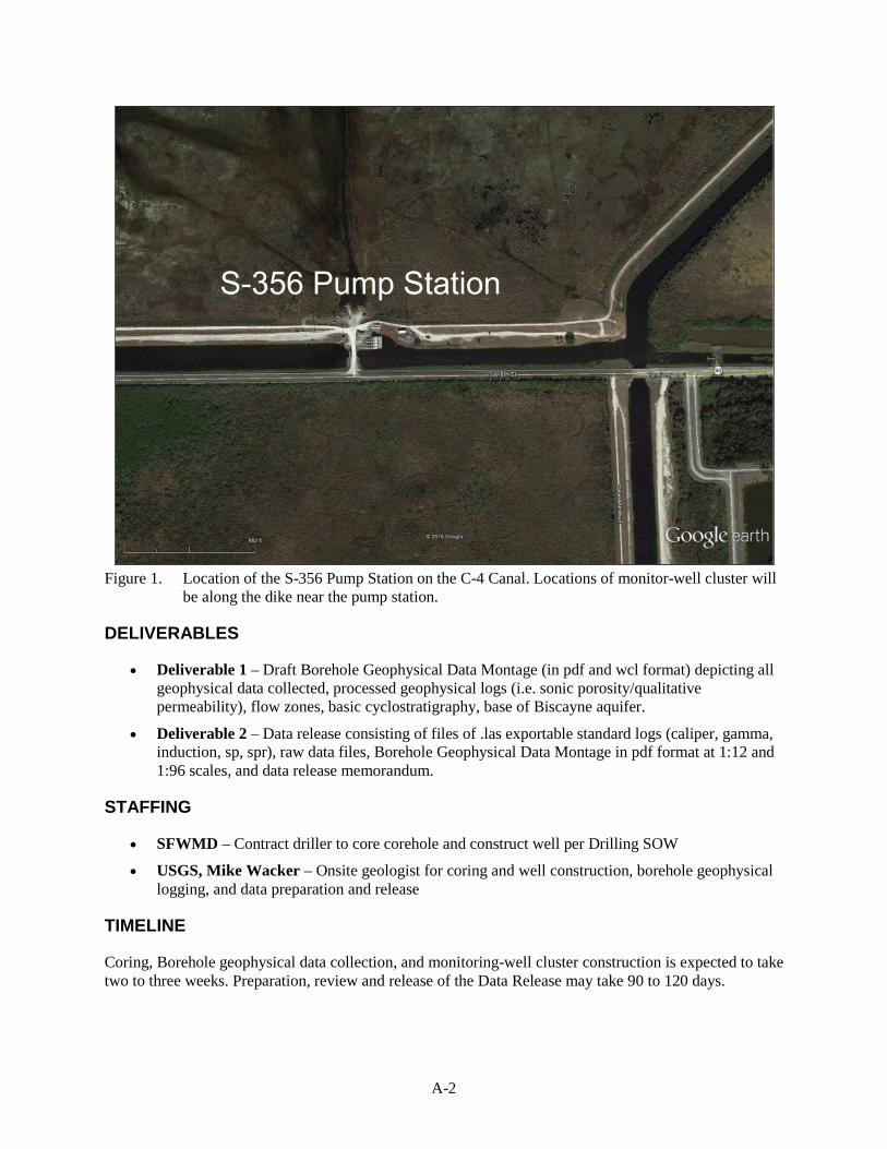
Figure 1. Location of the S-356 Pump Station on the C-4 Canal. Locations of monitor-well cluster will
be along the dike near the pump station.
DELIVERABLES
• Deliverable 1 – Draft Borehole Geophysical Data Montage (in pdf and wcl format) depicting all geophysical data collected, processed geophysical logs (i.e. sonic porosity/qualitative permeability), flow zones, basic cyclostratigraphy, base of Biscayne aquifer.
• Deliverable 2 – Data release consisting of files of .las exportable standard logs (caliper, gamma, induction, sp, spr), raw data files, Borehole Geophysical Data Montage in pdf format at 1:12 and 1:96 scales, and data release memorandum.
STAFFING
• SFWMD – Contract driller to core corehole and construct well per Drilling SOW
• USGS, Mike Wacker – Onsite geologist for coring and well construction, borehole geophysical logging, and data preparation and release
TIMELINE
Coring, Borehole geophysical data collection, and monitoring-well cluster construction is expected to take two to three weeks. Preparation, review and release of the Data Release may take 90 to 120 days.

A-3
ESTIMATED COSTS
Total Cost: $19,232
USGS cost share: $7,692.96
SFWMD cost share: $11,539.04
B-1
APPENDIX B STATEMENT OF WORK FOR INSTALLATION OF MONITOR WELLS.
Drill and install a four-well monitoring cluster at the S-356 pump station, Miami-Dade County, Florida
I. INTRODUCTION
This monitor well drilling project is being conducted to support testing of the S-356 pump station in Miami-Dade County, Florida. Site location maps are shown in Figures 1 and 2. The study will help assess the hydrologic interactions between surface water and groundwater when the pump station is operated. The project site includes the pump station, water control structure, large telemetry tower, and associated building, as shown in Figure 3.
II. GENERAL INFORMATION AND OVERVIEW
2.1 Scope of Work
The South Florida Water Management District (DISTRICT) seeks a State of Florida licensed water well contractor (CONTRACTOR) to install a four-well monitoring cluster at the S-356 pump station. This project involves drilling a pilot hole between approximately 75 and 90 feet below land surface, sampling continuously from the land surface to the bottom of the borehole by wireline or conventional coring on the deepest borehole, air developing the pilot hole to allow for optical borehole imaging and other geophysical logs, conversion of the pilot hole to a monitor well, installation of three more monitor wells, and well development at the site shown.
Monitor wells will be completed at four different depths within the Surficial Aquifer System (SAS). It is anticipated, based on existing knowledge, that the four wells will be completed at approximately 18, 30, 44, and 75 feet below land surface (bls). Actual depths will be based on the depths of flow zones identified by the optical borehole imaging conducted on the pilot hole by the U.S. Geological Survey (USGS). The wells will be constructed using 2-inch threaded polyvinyl chloride (PVC) casing and will require 2-foot screened intervals. All screens will be placed at the appropriate intervals and all wells will be in separate boreholes.
The DISTRICT or USGS will provide an on-site geologist during drilling operations to oversee collection of field samples and data, and to oversee well construction operations. Based on the availability of funds, the DISTRICT may only complete a portion of the work. The DISTRICT reserves the right to terminate the contract without any further restitution other than payment for services rendered and material installed.
2.2 Permits and Utility Clearance
The drilling site is located on DISTRICT right-of way immediately adjacent to the S-356 pump station. The CONTRACTOR shall be responsible for obtaining any local, state, or federal drilling permits or occupational licenses, to obtain clearance from all applicable utilities, and to provide notification to local municipalities prior to the start of drilling operations. All site visits with a utility representative are the responsibility of the CONTRACTOR. The CONTRACTOR shall also conform to any local or county ordinances pertaining to noise levels and working hours, etc. to avoid any unnecessary delays. Should any unanticipated delays occur due to permit acquisition, the DISTRICT reserves the right to postpone the start of the contract.
B-2
2.3 Project Schedule and Time Constraints
The wells shall be constructed in a timely manner to minimize impacts to the site. Once work on a borehole has started, it must proceed until the total depth of the borehole is reached. Drilling (and other loud tasks) should be performed during normal working hours (7:00 a.m. to 7:00 p.m., Monday through Friday) unless permission is given by the DISTRICT site geologist. Drilling shall be completed within 45 days after contract award.
2.4 Equipment and Personnel
The DISTRICT requires that a Water Well CONTRACTOR, licensed in the State of Florida or the appropriate Water Management District, be responsible for work performed under the contract. A copy of the current Florida Water Well Contractor license must be submitted with the quotation. All equipment utilized by the CONTRACTOR and any subcontractor(s) must be in good working order. The CONTRACTOR shall provide and operate drilling and support equipment with adequate load/weight capacity for the projected drilling depths. There will be no compensation for downtime incurred due to equipment failure or personnel problems. Unnecessary delays or work stoppages because of equipment or personnel problems will not be accepted nor considered a valid reason for extending the length of the contract.
2.5 Final Deliverables
Deliverables to the DISTRICT shall include:
A) Successful collection of cores and unconsolidated sediments from all boreholes described in Section 4.1. All samples will be stored as described in Section 4.1.
B) Completion of straight, clear, and stable boreholes suitable for borehole geophysical logging, video imaging, and completion of monitor wells.
C) Completed monitor wells and boreholes, as described in Sections 4.1 through 4.7 and within the time frame stated in Section 2.3.
D) Submission of daily drilling logs at the completion of each site.
E) Well completion diagrams prepared using the Windows based Gint© program. These diagrams will be submitted in both hard and electronic copies in a format acceptable to the SFWMD. These will be delivered within one month of completing the last well.
Payment shall be made according to the schedule in Section VIII.
III. SITE INFORMATION AND ENVIRONMENTAL REQUIREMENTS
3.1 Site Description
The project site is located in a rural area of Miami-Dade County, on Tamiami Trail (US 41) approximately 1.3 miles west of Krome Avenue, as shown on Figures 1 and 2. Entrance to the drilling site is from Tamiami Trail over the S-334 spillway.
B-3
3.2 Minimizing Impacts of Drilling
Negative impact to the site property as a result of the drilling activities must be minimized.
• The staging areas must be secured in order to prevent mishaps with the general public and to prevent vandalism to equipment and supplies. The CONTRACTOR is responsible for securing the drill sites.
• Activity at the drill site is restricted to specified, small areas.
• No vegetation will be cut without permission from the DISTRICT project manager or site geologist.
• If dry weather conditions make the risk of wildfires high, personnel must refrain from smoking or use of potential ignition sources. At other times, smoking is permitted if all cigarette butts are properly disposed of. At no time shall they be thrown on the ground.
• At all sites, drilling (and other loud tasks) should be performed during normal working hours (7:00 a.m. to 7:00 p.m., Monday through Friday) unless permission is given by the DISTRICT site geologist.
3.3 Mobilization, Demobilization and Site Cleanup and Staging Area Security
Mobilization shall include costs for all materials, equipment and labor required to prepare the site for drilling operations, install appropriate pit or surface casing (if necessary), and conduct any other measures that the CONTRACTOR feels are necessary to protect and secure their equipment during drilling operations. Part of the mobilization/set-up and demobilization costs may entail meeting several environmental requirements. The cost for providing the required equipment/facilities and services shall be part of the mobilization/demobilization price.
A) The CONTRACTOR may use the drill site as a staging area for equipment, supplies, and equipment cleaning. The site is unsecured and open to the public. Care must be taken to secure the site to protect equipment and supplies and to avoid mishaps in regards to the general public. The CONTRACTOR shall maintain the site and staging area in an orderly and functional manner during all drilling and well construction operations. Inoperable equipment or equipment that will not be used within a one (1) week period should not be stored or remain on the site.
B) The CONTRACTOR shall be responsible for removing debris and trash from the drill sites daily.
C) The CONTRACTOR shall steam clean the rig, drilling components, and all materials to be placed in the well bores according to the guidelines in Section 3.4, Equipment Cleaning.
D) The CONTRACTOR may spread and grade all well cuttings at the drill site. Drilling fluids may be discharged to land surface at the drill site. No discharge of cuttings or drilling fluids will be permitted into proximal surface waters (Tamiami Canal) or surface drains.
E) The CONTRACTOR shall comply with all Occupational Safety and Health Administration (OSHA)/United States Environmental Protection Agency (EPA) requirements regarding heavy equipment, electrical and mechanical operations, storage of compressed and flammable gases, and storage and handling of hazardous materials. Necessary personal safety equipment and containment and absorbent materials will be required on site for the duration of drilling operations. If conditions exist that may be in violation of either OSHA or EPA standards, a site visit from the appropriate representative may be requested by the DISTRICT.
B-4
F) Once all drilling and well construction operations have ceased, the CONTRACTOR is required to remove all equipment and restore the sites to original grade and condition. A DISTRICT representative must approve site restoration prior to mobilizing to the next site.
3.4 Equipment Cleaning
The wells may be used for long-term environmental monitoring. As such, extreme care must be taken in the installation process to prevent any cross-contamination from any other drill sites and from general contamination. All equipment used in the borehole and all equipment that could transport sediments from one site to another must be cleaned according to the following:
A) The CONTRACTOR shall wash (utilizing Liquinox™ soap) and steam clean the rig prior to starting any drilling activities. The drilling rig components (drill rods, augers, and bits) pumps, grout barrels, shovels, wheelbarrows, hoses, split spoons, coring barrels, and temporary casing must be steamed cleaned in the same manner prior to use and between each hole. The acrylic liners used in obtaining and storing unconsolidated samples and the caps shall all be washed with Liquinox™ soap and thoroughly rinsed, prior to use.
B) The CONTRACTOR shall provide ample buckets, brushes, water and Liquinox solution to complete the cleaning as described in this document.
C) During the cleaning process and well construction, all personnel shall wear latex type (disposable) gloves to prevent contamination. The CONTRACTOR shall provide sawhorses or a small bench(s) to support the risers prior to installation and shall plastic wrap the cleaned components to protect them from new contamination.
D) The CONTRACTOR shall steam clean and flush all tank interiors off-site before mobilizing to the initial site.
IV. GENERAL DRILLING AND WELL CONSTRUCTION REQUIREMENTS
4.1 Formation Samples
The CONTRACTOR will obtain continuous geologic samples from the pilot hole. The 4-inch coring shall be accomplished via wireline coring with diamond surface set-face discharge system bit or with conventional coring. Unconsolidated samples must be obtained via wireline coring (with appropriate catcher). The CONTRACTOR will provide multiple coring devices to speed the process. The site geologist will be responsible to collect and describe samples and cores obtained during pilot-hole drilling operations. The CONTRACTOR shall provide the geologist safe access to inspect the samples, and shall accommodate the geologist in retrieving samples, including moderating drill rates and circulation, if necessary.
Due to the scientific and engineering nature of this project, the collection of geologic samples, particularly the 4-inch diameter cores, is extremely important. The SFWMD will only pay for samples with 75% or more of recovered sediment. If the minimum sample recovery is not obtained for a particular interval of a monitor well, the CONTRACTOR may be required to core that interval on one of the other wells in the cluster. If sufficient sediment samples are obtained from the pilot hole, no samples will be needed from the other wells.
Continuous Wireline Sampling - Wireline coring is preferred to maximize the amount of core recovery. All wireline cores shall be obtained using a core barrel where the inner barrel is locked to the outer barrel and the core catcher is a small core bit, protruding a few inches ahead of the main core bit. All wireline core
B-5
samples are to be four inches in diameter. Any unconsolidated samples obtained by wireline coring will be collected in clear plastic liners with caps. Liners and caps are to be new and free from cracks or other defects and washed before use. Caps must be placed on each end of the liner and secured prior to storage. The site geologist will identify and store samples as specified.
4.2 Reaming
It is likely that the coring will produce a pilot hole with a diameter of approximately 6.5-inches. If the pilot hole is smaller than this, the CONTRACTOR will ream the entire depth of the pilot hole to a diameter of 6.5-inches to allow USGS staff to run geophysical logs in the pilot hole.
4.3 Well Development for Logging
After the coring/reaming of the pilot hole is complete, the CONTRACTOR will develop the borehole to allow the USGS to run geophysical logs. This development is needed to remove all visible particulate matter prior to logging. The CONTRACTOR will develop the borehole with an air-lift system until the site geologist approves the borehole for logging. After the USGS has completed the geophysical logging in the pilot hole, the CONTRACTOR will construct the monitor well.
All boreholes must be developed using an air lift method. The CONTRACTOR shall furnish all equipment, pumps, oil/water separators for use on the compressors, compressors, piping, and appurtenances required to successfully develop each borehole.
4.4 Mud Rotary/Reverse Air/Dual Wall Drilling
After the geophysical logging of pilot hole has been completed, the CONTRACTOR will drill the remaining three monitor wells. These will be drilled using the mud rotary, reverse air, or dual wall methods. If sufficient sediment samples were obtained from the deep monitor well, no samples will be needed from these wells. If the mud rotary method is used, the CONTRACTOR must dispose of drilling fluids in the manner described in Section 3.3. No discharge of cuttings or drilling fluids will be permitted into proximal surface waters (Tamiami Canal) or surface drains.
4.5 Drilling Logs
Accurate drilling records are critical to the success of this project. The CONTRACTOR shall furnish the SFWMD with a daily drilling record. The log shall accurately describe the following: geologic materials and depths encountered, depths of lost circulation zone(s) and methods of regaining circulation, drilling rate, time, depth, description of any unusual occurrences or problems during drilling, diameters and lengths of drill rod and casing, and any other work performed at the site. The drilling logs must be available on site for review by the SFWMD and the logs will become the property of the SFWMD upon completion of the wells.
4.6 Borehole Casing (PVC)
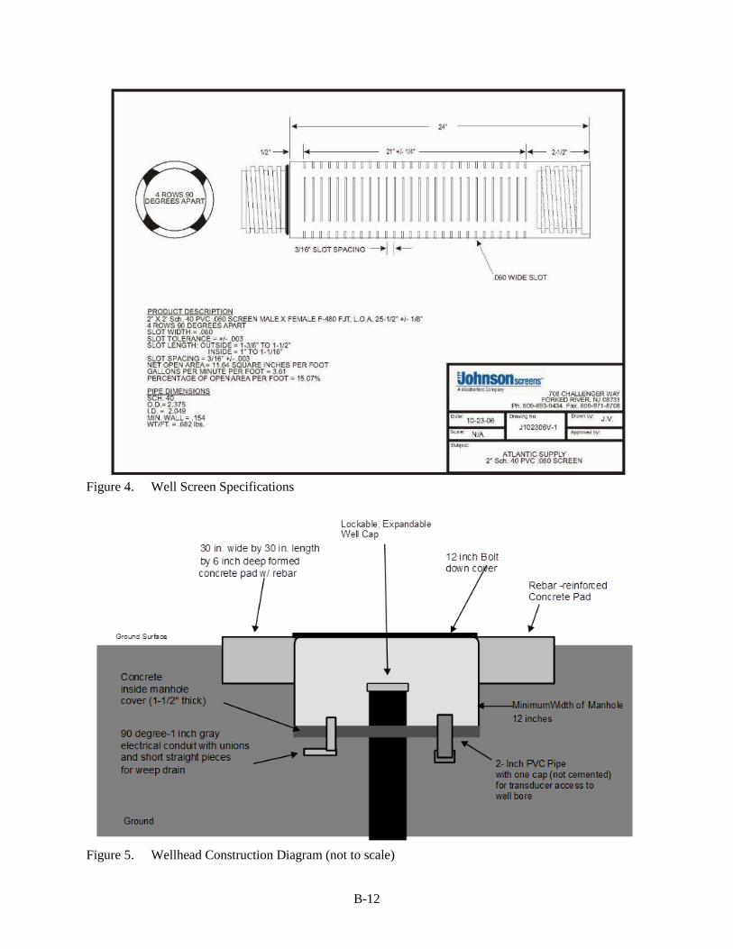
The site geologist will specify the depth of the casing and the screen intervals. For this proposal, it should be assumed the cluster will have wells of approximately 18 feet, 30 feet, 44 feet, and 75 to 90 feet bls. The CONTRACTOR shall provide two-inch diameter, schedule 40 PVC Tri-Loc riser (or equivalent). Well screens will be 0.060-inch slot size, two-inch diameter, schedule 40 PVC (Figure 4). The wells screens will be two feet long in each well. All monitor wells will be completed below grade with a 16” diameter bolt-down, sealing, manhole cover as shown in Figure 5. All well casing joints shall be connected by threaded connections with manufacturer-supplied "O" rings, cleaned and sealed in plastic at the factory.
B-6
The SFWMD will only authorize payment for casing installed to the actual depth and grouted into place back to land surface. All casing shall be of new, first quality material and free of defects in manufacturing and handling.
4.7 Well Casing Centralizers
All monitor wells shall be fitted with centralizers constructed of PVC. If different material is proposed, it must be approved by the SFWMD prior to commencement of fieldwork. The centralizers will be spaced about every 20 feet beginning 2-feet above the top of the screen. All centralizers must be installed in alignment to allow insertion of a tremie pipe to the total depth of the well.
4.8 Well Construction/Cement Grouting
All work performed shall conform to State of Florida well drilling practices and to AWWA standards. The CONTRACTOR shall be responsible for calculating volumes pumped during construction/grouting operations. The site geologist will review methods and volumes prior to commencement of pumping cement grout. The gravel pack must be dropped into the annular space using a tremie line and should be hard tagged at 1 to 2 feet above the top of the screen. The CONTRACTOR will then pump about 1 foot of bentonite on top of the sand pack. If the CONTRACTOR prefers, they may replace the bentonite layer with 1-foot of fine sand pumped on top of the gravel pack. These will be allowed to settle for at least ½ hour before pumping the cement grout. The method used must completely fill grout from the bottom of the annular space to the surface. A minimum of eight (8) hours setting time shall be required between successive cement lifts. All subsequent cement lifts shall be tagged by the tremie method prior to installing an additional stage.
4.9 Wellhead Completion
All monitor wells will be recessed below grade. These will be enclosed in a 16-inch diameter ‘meter vault’ type protective box (Figure 5) with bolt down access lids. These boxes must be made of steel or cast iron and dipped in primer once and in Rustoleum brand red paint twice before installation. The well recesses will have a 1-inch diameter drain hole to remove excess water in the recess. Additionally, the CONTRACTOR will install a 2-inch 90° sweep made of gray electrical conduit that extends one inch above the concrete and extends several inches below and to the side of the concrete pad. This will provide access for a transducer cable. The well will be completed and sealed at the surface with a 30” x 30” x 10” cement pad (with #8 reinforcing bars) that slopes slightly away from the well. The reinforcing bar must be centered within the depth of the cement pad.
4.10 Well Development
The boreholes will be developed several times. The development in preparation for logging is described in Section 4.3. The final development will take place after the wells are constructed. The CONTRACTOR will develop the wells until all visible particulate matter is removed and the water quality field parameters (pH, temperature, specific conductivity) are stable. At a minimum, each well shall be developed for one hour. The CONTRACTOR will use a YSI (or similar type) water quality sensor to monitor field parameters during development. A geologist or technician will be on site to provide and use the water quality sensor. It is anticipated that the discharge water from well development will be pumped onto the ground surface.
All boreholes and wells must be developed using an air lift method. The CONTRACTOR shall furnish all equipment, pumps, oil/water separators for use on the compressors, compressors, piping, and appurtenances required to successfully develop each borehole and well.

B-7
V. RECOMMENDED PROCEDURES
Listed below is the summary of the drilling and construction procedures and proposed sequence of activities to be conducted at each site of each new borehole.
A) Prior to mobilization, the CONTRACTOR will steam clean and flush all tank interiors and fill tanks with clean water as specified in Section 3.4.D.
B) The CONTRACTOR will mobilize to the drilling sites, ensure all drilling and containerization equipment is properly set-up, and complete all necessary steam cleaning of drill rig, equipment, and supplies.
C) The CONTRACTOR will set up the drill rig at the designated location, transport equipment and supplies to site, prepare equipment for drilling operations, and complete any additional cleaning.
D) The CONTRACTOR will begin the pilot hole with the selected methodology that will provide a 4-inch core. This will provide a nominal 6.5-inch borehole. The CONTRACTOR will store all samples in the clear plastic liners with well name, date, sample interval, and sample number with the top and bottom of the sample marked. For cores, the CONTRACTOR will also mark the direction of sample layout. All sample storage boxes will be labeled as indicated in Section 4.1. The CONTRACTOR will continue the pilot hole to the depth specified by the site geologist, estimated to be approximately 75 feet.
F) Due to the nature of this project, it is important to facilitate collection of digital borehole image logs. Therefore, the drilling method for the initial pilot hole should not include the use of drilling mud until the digital borehole image log has been run, unless approved by the site geologist. The CONTRACTOR is responsible for maintaining a clean borehole for geophysical logging. If wireline coring has been used for the entire borehole and the borehole is nominally 6.5-inches in diameter, the CONTRACTOR will proceed to develop the borehole. The CONTRACTOR will use an air-lift system constructed from 3-inch steel tubing with 1/2-inch air-line, from total depth to surface until the water in well bore is replaced with clear water.
G) Logging will be conducted on the completed pilot hole by USGS staff. The drilling CONTRACTOR is responsible for providing a clear, straight, and stable hole for all logging operations. If the borehole is left open overnight or longer prior to beginning the logging, the CONTRACTOR will be required to tag the bottom with the drill bit and recirculate drilling fluids to the total depth.
H.) When the USGS has completed the final logging in the four additional boreholes, the CONTRACTOR will assemble the borehole casing in the following manner: a) assemble the well point and well screen to first riser; b) install the first centralizer two feet above the top of the screen; c) anchor centralizer, spread to the correct diameter and insert screen and riser into the (reamed) borehole; d) assemble the remaining risers, attach the centralizers at the appropriate locations (every 20 feet) on the risers, spread centralizers to the correct diameter, and connect to already installed riser. All centralizers are to be oriented the same to allow use of the tremie pipe within the annulus. As stated in Section 3.4, all centralizers, well risers, and well screens shall be steam cleaned and disposable latex type gloves shall be worn at all times during the cleaning, well construction, and installation process.
I) After the PVC has been installed to the appropriate depth, the gravel pack, bentonite seal, and grout can be emplaced. The gravel pack (1/4 by 1/8 inch gravel) must be dropped into the borehole via a
B-8
1-inch tremie pipe and to a level 1 to 2 feet above the well screen. A hard tag will confirm placement of the gravel pack. A 1-foot bentonite seal shall be pumped on top of the sand pack and then grouted to land surface using 5% bentonite-cement slurry. All grouting work performed shall conform to State of Florida well drilling practices and AWWA standards. The CONTRACTOR shall be responsible for calculating volumes pumped during grouting operations. A minimum of eight (8) hours setting time shall be required between successive cement lifts. All subsequent cement lifts shall be tagged by the tremie method prior to installing an additional stage
J) When the final lift has had time to set (at least 8 hours), the well shall be developed until the water becomes clear or water quality field parameters become stable. At a minimum, the well shall be developed for one hour. Development water may be discharged onto the ground if the water is determined to have a specific conductance of less than 750 uS/cm.
O) All necessary site restoration will be completed at the site as stated in Section 3.3 – E.
VI. WELL ABANDONMENT
Should a borehole or well be determined by the DISTRICT geologist to be unacceptable, the CONTRACTOR shall abandon the hole by grouting the hole from bottom to surface, following DISTRICT well abandonment methods. A well may be declared unacceptable due to the CONTRACTOR’s failure to complete the drilling, incorrect casing placement, a lost tool, or for any other CONTRACTOR failures to complete the well in a satisfactory manner. Under these circumstances, no payment will be made to the CONTRACTOR for the well abandonment operations and the CONTRACTOR must provide a new well, meeting the original specifications, at no additional cost to the DISTRICT.
VII. STANDBY TIME
During the normal progression of work, the CONTRACTOR will be authorized standby time when it is necessary for DISTRICT personnel to perform work or conduct tests that are not specified in the Contract, such as the optical borehole imaging. The CONTRACTOR will be notified in advance and the amount of time authorized will be mutually agreed upon and noted on the CONTRACTOR’s daily logs.
VIII. PAYMENT SCHEDULE
Payment will be remitted after completion and acceptance of all deliverables in accordance with this SOW.
B-9
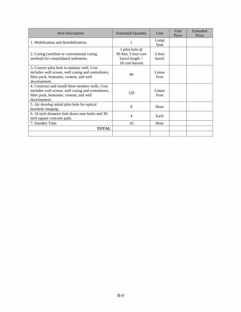
Item Description Estimated Quantity Unit Unit Price
Extended Price
1. Mobilization and demobilization. 1 Lump Sum
2. Coring (wireline or conventional coring method) for consolidated sediments.
1 pilot hole @ 90 feet; 5 foot core
barrel length = 18 core barrels
5-foot barrel
3. Convert pilot hole to monitor well. Cost includes well screen, well casing and centralizers, filter pack, bentonite, cement, and well development.
90 Linear Foot
4. Construct and install three monitor wells. Cost includes well screen, well casing and centralizers, filter pack, bentonite, cement, and well development.
120 Linear Foot
5. Air develop initial pilot hole for optical borehole imaging. 8 Hour
6. 16-inch diameter bolt-down man holes and 30-inch square concrete pads. 4 Each
7. Standby Time 16 Hour TOTAL
B-10
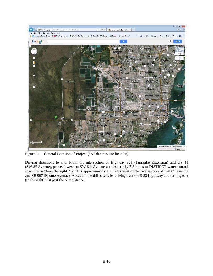
Figure 1. General Location of Project (“A” denotes site location)
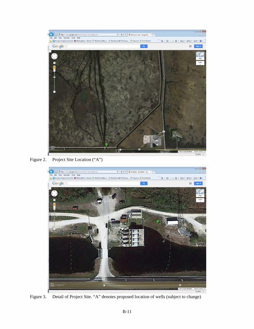
Driving directions to site: From the intersection of Highway 821 (Turnpike Extension) and US 41 (SW 8th Avenue), proceed west on SW 8th Avenue approximately 7.5 miles to DISTRICT water control structure S-334on the right. S-334 is approximately 1.3 miles west of the intersection of SW 8th Avenue and SR 997 (Krome Avenue). Access to the drill site is by driving over the S-334 spillway and turning east (to the right) just past the pump station.
B-11
Figure 2. Project Site Location (“A”)
Figure 3. Detail of Project Site. “A” denotes proposed location of wells (subject to change)
B-12
Figure 4. Well Screen Specifications
Figure 5. Wellhead Construction Diagram (not to scale)
C-1
APPENDIX C PRELIMINARY (DRAFT) PLOT OF THE GEOPHYSICAL LOGS
Figure 1. Geophysical Logs (OBI, Acoustic Borehole Imagery, Caliper, Flowmeter, Magnetic
Induction, Spontaneous Potential, Single Point Resistivity, Natural Gamma)
D-1
APPENDIX D INITIAL WATER QUALITY DATA
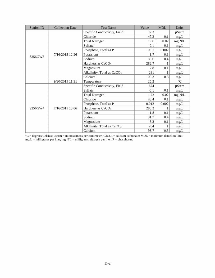
Station ID Collection Date Test Name Value MDL Units
S356GW1
7/16/2015 11:48 No Bottle Sample 0 --
7/24/2015 9:02
Hardness as CaCO3 -1 1 mg/L Sulfate -0.1 0.1 mg/L Chloride -0.1 0.1 mg/L Magnesium -0.1 0.1 mg/L Total Nitrogen -0.02 0.02 mg N/L Potassium -0.1 0.1 mg/L Sodium -0.4 0.4 mg/L Phosphate, Total as P -0.002 0.002 mg/L Alkalinity, Total as CaCO3 -1 1 mg/L Calcium -0.3 0.3 mg/L
7/24/2015 9:48
Magnesium 10 0.1 mg/L Sulfate 10.1 0.1 mg/L Chloride 45.3 0.1 mg/L Total Nitrogen 0.392 0.02 mg N/L Potassium 3.3 0.1 mg/L Hardness as CaCO3 204.3 1 mg/L Sodium 62.1 0.4 mg/L Calcium 65.3 0.3 mg/L Alkalinity, Total as CaCO3 271 1 mg/L Phosphate, Total as P 0.048 0.002 mg/L Dissolved Oxygen 0.54 mg/L pH, Field 7 -- Specific Conductivity, Field 665 µS/cm Temperature 25 °C
S356GW2
7/16/2015 9:25
Calcium -0.3 0.3 mg/L Potassium -0.1 0.1 mg/L Sodium -0.4 0.4 mg/L Phosphate, Total as P -0.002 0.002 mg/L Total Nitrogen -0.02 0.02 mg N/L Chloride -0.1 0.1 mg/L Sulfate -0.1 0.1 mg/L Hardness as CaCO3 -1 1 mg/L Alkalinity, Total as CaCO3 -1 1 mg/L Magnesium -0.1 0.1 mg/L
7/16/2015 11:06
Alkalinity, Total as CaCO3 300 1 mg/L Sulfate -0.1 0.1 mg/L Chloride 45 0.1 mg/L Calcium 101.8 0.3 mg/L Magnesium 7.6 0.1 mg/L Sodium 29.6 0.4 mg/L Hardness as CaCO3 285.5 1 mg/L Potassium 1.4 0.1 mg/L Total Nitrogen 1.94 0.02 mg N/L Specific Conductivity, Field 694 µS/cm Phosphate, Total as P 0.011 0.002 mg/L
D-2
Station ID Collection Date Test Name Value MDL Units
S356GW3 7/16/2015 12:26
Specific Conductivity, Field 683 µS/cm Chloride 47.3 0.1 mg/L Total Nitrogen 1.86 0.02 mg N/L Sulfate -0.1 0.1 mg/L Phosphate, Total as P 0.01 0.002 mg/L Potassium 1.7 0.1 mg/L Sodium 30.6 0.4 mg/L Hardness as CaCO3 282.7 1 mg/L Magnesium 7.8 0.1 mg/L Alkalinity, Total as CaCO3 291 1 mg/L Calcium 100.3 0.3 mg/L
9/30/2015 11:21 Temperature 25.2 °C
S356GW4 7/16/2015 13:06
Specific Conductivity, Field 674 µS/cm Sulfate -0.1 0.1 mg/L Total Nitrogen 1.72 0.02 mg N/L Chloride 48.4 0.1 mg/L Phosphate, Total as P 0.012 0.002 mg/L Hardness as CaCO3 280.2 1 mg/L Potassium 1.8 0.1 mg/L Sodium 31.7 0.4 mg/L Magnesium 8.2 0.1 mg/L Alkalinity, Total as CaCO3 284 1 mg/L Calcium 98.7 0.3 mg/L
°C = degrees Celsius; µS/cm = microsiemens per centimeter; CaCO3 = calcium carbonate; MDL = minimum detection limit; mg/L = milligrams per liter; mg N/L = milligrams nitrogen per liter; P = phosphorus.


![Rafay Systems Multi-Cluster Management PlatformDatasheet] Rafay Systems Multi-Cluster... · based managed Kubernetes services (e.g. Amazon EKS) in the cloud. Monitoring, Visibility](https://img.pdfslide.net/doc/110x75/5f05f0987e708231d4157bcc/rafay-systems-multi-cluster-management-platform-datasheet-rafay-systems-multi-cluster.jpg)