Embed Size (px)
Citation preview
I N S T A L L A T I O N I N S T R U C T I O N S
Instrucciones de instalaciónInstallationsanleitungInstruções de Instalação
Istruzioni di installazioneInstallatie-instructiesInstructions d´installation
RPA Elite Series Projector MountsSpanish Product DescriptionGerman Product Description
Portuguese Product Description Italian Product DescriptionDutch Product Description
French Product Description
RPMA/RPMB/RPMC Series
RPMA/RPMB/RPMC Series Installation Instructions
2
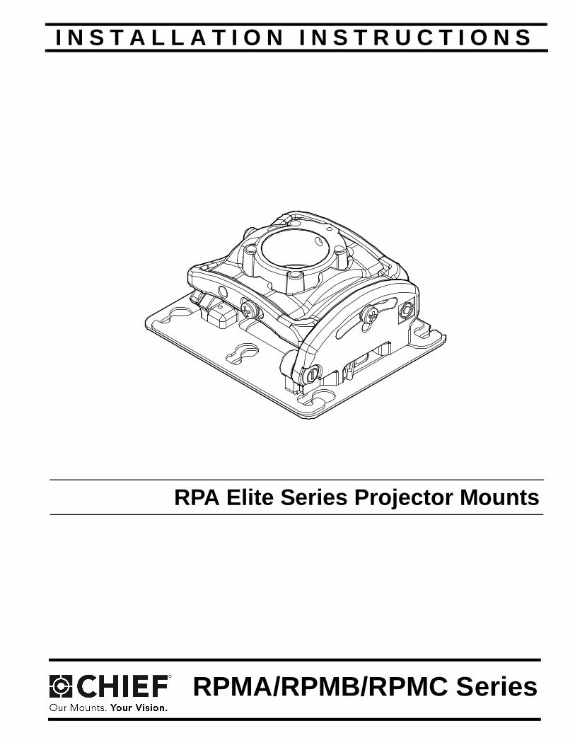
NOTE: RPMA, RPMB, and RPMC models are included inthese installation instructions. Throughout theseinstructions "RPMX" is used to designate all of themodels covered by these instructions.
DISCLAIMERMilestone AV Technologies and its affiliated corporations andsubsidiaries (collectively "Milestone"), intend to make thismanual accurate and complete. However, Milestone makes noclaim that the information contained herein covers all details,conditions or variations, nor does it provide for every possiblecontingency in connection with the installation or use of thisproduct. The information contained in this document is subjectto change without notice or obligation of any kind. Milestonemakes no representation of warranty, expressed or implied,regarding the information contained herein. Milestone assumesno responsibility for accuracy, completeness or sufficiency ofthe information contained in this document.Chief® is a registered trademark of Milestone AV Technologies.All rights reserved.
DEFINITIONSMOUNTING SYSTEM: A MOUNTING SYSTEM is theprimary Chief product to which an accessory and/or componentis attached.
ACCESSORY: AN ACCESSORY is the secondary Chiefproduct which is attached to a primary Chief product, and mayhave a component attached or setting on it.
COMPONENT: A COMPONENT is an audiovisual itemdesigned to be attached or resting on an accessory or mountingsystem such as a video camera, CPU, screen, display,projector, etc.
WARNING: A WARNING alerts you to the possibility ofserious injury or death if you do not follow the instructions.
CAUTION: A CAUTION alerts you to the possibility ofdamage or destruction of equipment if you do not follow thecorresponding instructions.
IMPORTANT SAFETY INSTRUCTIONS
WARNING: Failure to read, thoroughly understand, andfollow all instructions can result in serious personal injury,damage to equipment, or voiding of factory warranty! It is theinstaller’s responsibility to make sure all mounting systemsare properly assembled and installed using the instructionsprovided.
WARNING: Failure to provide adequate structural strengthfor this mounting system can result in serious personal injuryor damage to equipment! It is the installer’s responsibility tomake sure the structure to which this mounting system isattached can support five times the combined weight of allequipment. Reinforce the structure as required beforeinstalling the mounting system.
WARNING: Exceeding the weight capacity can result inserious personal injury or damage to equipment! It is theinstaller’s responsibility to make sure the combined weight ofall components attached to the RPMX does not exceed 50 lbs(22.7 kg).
• The weight capacity of the RPMX may be LIMITED tothe lowest weight capacity of any other mountingsystems/accessories located between the RPMX andthe supporting structure!
WARNING: Use this mounting system only for its intendeduse as described in these instructions. Do not useattachments not recommended by the manufacturer.
WARNING: Never operate this mounting system if it isdamaged. Return the mounting system to a service center forexamination and repair.
WARNING: Do not use this mounting system outdoors.
IMPORTANT ! : The RPMX mounting system is designed tobe:
• mounted to a 1-1/2" NPT or NPSM following ANSI/ASME B1.20.1 (Schedule 40, 0.154" minimumthickness aluminum - ASTM B221) threaded extensioncolumn;
• mounted to double 2" x 4" wood stud cross bracing(1-1/2" on center) between two 2" x 4" ceiling joists witha maximum drywall covering of 5/8";
• mounted to a concrete ceiling with a minimumthickness of 8" and a maximum drywall covering of5/8"; or
• suspended from four #10-24 grade ASTM A307 orbetter threaded rods (not included) which are securedto Unistrut®, angle or channel assembly overheadstructural members (trusses or I-beams) by #10-24grade ASTM A307 or better jam nuts (not included).
NOTE: RPMA / RPMB / RPMC Series may be used with ListedChief models WM110S, WM120S, WM130S,WM210S, WM220S, WM230S, WM240S, WM210SI,WM220SI, WM230SI, WM240SI, SL220 and LSB101(not included).
--SAVE THESE INSTRUCTIONS--

Installation Instructions RPMA/RPMB/RPMC Series
3
DIMENSIONS
TOOLS REQUIRED FOR INSTALLATION
PARTS
2.79
.88 5.40
ROLL ADJUSTMENTPOINT 3
5.50
6.50
1.50" DIA NPT
4.50
5.50
SECURITY LOCK
SECURITY SWITCH
PITCH ADJUSTMENTPOINT 20
YAW ADJUSTMENTPOINT 20
DIMENSIONS: INCHES
1/4" (6.4mm) dia. (concrete) 3/32" (2.4mm) dia. (wood)
5/32" - security (included)
A (1)[RPMA/-B/-C]
B (1)[Example of SLM bracket]
RPMA/RPMB/RPMC Series Installation Instructions
4
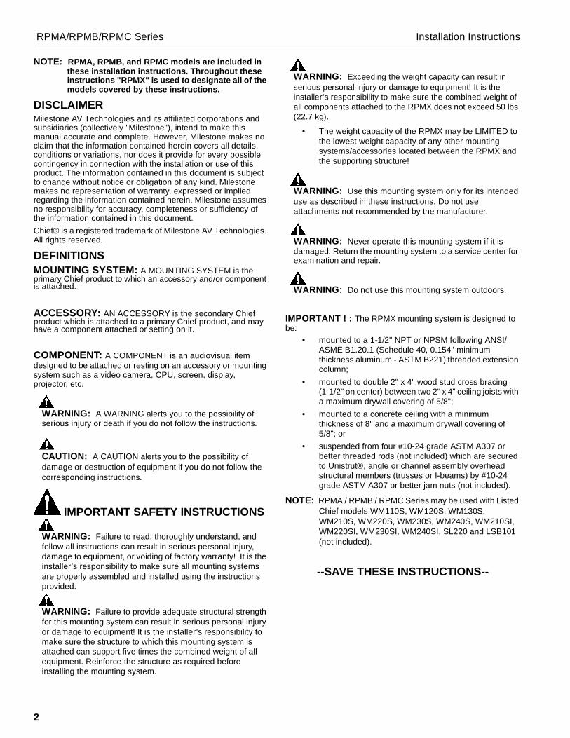
LEGENDTighten Fastener
Serrez les fixations
Serrare il fissaggio
Befestigungsteil festziehen
Apretar elemento de fijación
Bevestiging vastdraaien
Apertar fixador
Loosen Fastener
Desserrez les fixations
Allentare il fissaggio
Befestigungsteil lösen
Aflojar elemento de fijación
Bevestiging losdraaien
Desapertar fixador
Phillips Screwdriver
Tournevis à pointe cruciforme
Cacciavite a stella
Kreuzschlitzschraubendreher
Destornillador Phillips
Kruiskopschroevendraaier
Chave de fendas Phillips
Hex-Head Wrench
Clé à tête hexagonale
Chiave esagonale
Sechskantschlüssel
Llave de cabeza hexagonal
Zeskantsleutel
Chave de cabeça sextavada
Open-Ended Wrench
Clé à fourche
Chiave a punte aperte
Gabelschlüssel
Llave de boca
Steeksleutel
Chave de bocas
By Hand
À la main
A mano
Von Hand
A mano
Met de hand
Com a mão
Pencil Mark
Marquage au crayon
Segno a matita
Stiftmarkierung
Marcar con lápiz
Potloodmerkteken
Marcar com lápis
Drill Hole
Percez un trou
Praticare un foro
Bohrloch
Perforar
Gat boren
Fazer furo
Adjust
Ajuster
Regolare
Einstellen
Ajustar
Afstellen
Ajustar
Hammer
Martillo
Hammer
Martelo
Martello
Hamer
Marteau
Target of Projector
Punto de enfoque del proyector
Ziel des Projektors
Mira do projector
Punto di proiezione
Doel van de projector
Cible du projecteur
Security Wrench
Clé de sécurité
Chiave di sicurezza
Sicherheitsschlüssel
Llave de seguridad
Veiligheidssleutel
Chave de segurança

Installation Instructions RPMA/RPMB/RPMC Series
5
PREPARATIONLocate Mounting Site
WARNING: IMPROPER INSTALLATION MAY LEAD TOPROJECTOR MOUNT FALLING CAUSING SEVEREPERSONAL INJURY OR DAMAGE TO EQUIPMENT! It isthe installers responsibility to make certain the structure towhich the projector mount is being mounted is capable ofsupporting five times the weight of the projector mount and allattached equipment. Reinforce the structure as requiredbefore installing the projector mount.
1. Determine required position of the RPMX projector mount.
2. Determine required distance of the projector mount from thescreen using the projector specifications.
NOTE: Proceed to Installing to 1-1/2" Threaded ExtensionColumn, Installing to Wood Framework, Installingto Concrete Ceiling, or Installing to Threaded Rodsection, as appropriate.
INSTALLATIONInstalling to 1-1/2" Threaded Extension Column1. Install 1-1/2" NPT or NPSM following ANSI/ASME B1.20.1
(Schedule 40, 0.154" minimum thickness steel or aluminum- ASTM B221) threaded extension column (not included)into threaded collar until tight, with a minimum of fourthreads engaged.
2. Thread RPMX projector mount (A) onto the threadedextension column (not included) until hand tight.
3. Turn RPMX clockwise or counter-clockwise until front ofmount is facing target.
IMPORTANT ! : When RPMX is properly positioned, theset screw access hole should be pointing directly attarget, or 180° AWAY from target.
4. Secure RPMX to pipe by turning set screw with a 5/32" hexkey until tight. (See Figure 1)
CAUTION: DO NOT OVERTIGHTEN! Over tightening ofset screw can damage threads on pipe.
Figure 1
5. Turn security screw (access from bottom of RPMX) (SeeFigure 2) using a Phillips screwdriver until set screw cannotbe seen through set screw access hole in RPMX. (SeeFigure 1)
Figure 2
6. Proceed to Installing Projector with Interface Bracketsection.
2
4
(A)
Set screwaccess hole
x 1
Threaded extension column (not included)
(not included)
(RPMX bottom view)
5 x 1
Security screw

RPMA/RPMB/RPMC Series Installation Instructions
6
Installing to Wood Framework (Joists)1. Using the RPMX as a guide, mark four mounting hole
locations. (See Figure 3)
2. Drill four 3/32" (2.4mm) dia. pilot holes to a depth of 1-3/4"(45mm) deep.
Figure 3
3. Align four mounting holes in RPMX with four pilot holes.
IMPORTANT ! : When RPMX is properly positioned, theset screw access hole should be pointing directly attarget, or 180° AWAY from target.
4. Secure RPMX to structure using four 1/4 x 3" ASTM A307,Grade A lag bolts (not included) and four 1/4" Grade 2 flatwashers (not included). (See Figure 4)
Figure 4
5. Proceed to Installing Projector with Interface Bracketsection.
Installing to Concrete Ceiling
WARNING: The RPMX is designed to be mounted to aconcrete ceiling with a minimum thickness of 8" and amaximum drywall covering of 5/8".
1. Using the RPMX as a guide, mark four mounting holelocations on ceiling using a pencil or similar tool.
2. Drill four 1/4" (6.4mm) dia. pilot holes to a depth of 2-1/2"(64mm) deep. (See Figure 5)
Figure 5
Ø 2.4mm(Ø 3/32”)
45mm(1-3/4”)
x 41
2
Pilotholedimensions
4
3
x 4
2x 4
1Ø 6.4mm(Ø 1/4”)
64mm(2-1/2”)
Pilotholedimensions
Installation Instructions RPMA/RPMB/RPMC Series
7
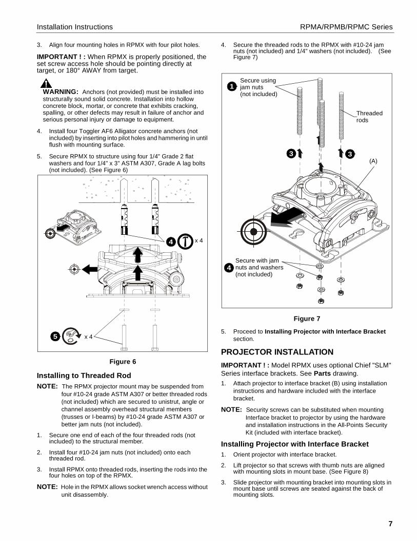
3. Align four mounting holes in RPMX with four pilot holes.
IMPORTANT ! : When RPMX is properly positioned, theset screw access hole should be pointing directly attarget, or 180° AWAY from target.
WARNING: Anchors (not provided) must be installed intostructurally sound solid concrete. Installation into hollowconcrete block, mortar, or concrete that exhibits cracking,spalling, or other defects may result in failure of anchor andserious personal injury or damage to equipment.
4. Install four Toggler AF6 Alligator concrete anchors (notincluded) by inserting into pilot holes and hammering in untilflush with mounting surface.
5. Secure RPMX to structure using four 1/4" Grade 2 flatwashers and four 1/4" x 3" ASTM A307, Grade A lag bolts(not included). (See Figure 6)
Figure 6
Installing to Threaded RodNOTE: The RPMX projector mount may be suspended from
four #10-24 grade ASTM A307 or better threaded rods(not included) which are secured to unistrut, angle orchannel assembly overhead structural members(trusses or I-beams) by #10-24 grade ASTM A307 orbetter jam nuts (not included).
1. Secure one end of each of the four threaded rods (notincluded) to the structural member.
2. Install four #10-24 jam nuts (not included) onto eachthreaded rod.
3. Install RPMX onto threaded rods, inserting the rods into thefour holes on top of the RPMX.
NOTE: Hole in the RPMX allows socket wrench access withoutunit disassembly.
4. Secure the threaded rods to the RPMX with #10-24 jamnuts (not included) and 1/4" washers (not included). (SeeFigure 7)
Figure 7
5. Proceed to Installing Projector with Interface Bracketsection.
PROJECTOR INSTALLATIONIMPORTANT ! : Model RPMX uses optional Chief "SLM"Series interface brackets. See Parts drawing.1. Attach projector to interface bracket (B) using installation
instructions and hardware included with the interfacebracket.
NOTE: Security screws can be substituted when mountingInterface bracket to projector by using the hardwareand installation instructions in the All-Points SecurityKit (included with interface bracket).
Installing Projector with Interface Bracket1. Orient projector with interface bracket.
2. Lift projector so that screws with thumb nuts are alignedwith mounting slots in mount base. (See Figure 8)
3. Slide projector with mounting bracket into mounting slots inmount base until screws are seated against the back ofmounting slots.
4
x 45
x 4
3
1Secure using
3
4Secure with jamnuts and washers(not included)
Threadedrods
(A)
jam nuts(not included)

RPMA/RPMB/RPMC Series Installation Instructions
8
WARNING: IMPROPER INSTALLATION CAN LEAD TOPROJECTOR FALLING RESULTING IN SERIOUSPERSONAL INJURY OR DAMAGE TO EQUIPMENT. Makecertain mounting slots in projector mount base slide underthumb screws and that screws are seated in the back of slots.
Figure 8
4. Verify mounting screws are properly seated in mountingslots in projector mount base.
5. Move locking lever to "LOCKED" position. (See Figure 8)
6. Insert key into lock and turn to secure projector to RPMX.
7. Route all cables, as required.
ADJUSTMENTSThe RPMX projector mount can be adjusted for pitch (verticalelevation), roll (horizontal tilt), and yaw (rotation).
WARNING: OVER-LOOSENING OR REMOVAL OFHARDWARE MAY RESULT IN PERSONAL INJURY ORSERIOUS DAMAGE TO EQUIPMENT! RPMX projectormount and hardware is to be loosened only enough to allowfor necessary movement.
YAW Adjustment (Rotation)1. Loosen YAW adjustment locking screw using a #2 Phillips
screwdriver. (See Figure 9)
2. Turn YAW micro-adjustment screw right or left using a #2Phillips screwdriver until image is properly aligned on target.
3. Tighten YAW adjustment locking screw using a #2 Phillipsscrewdriver.
Figure 9
Pitch Adjustment (Vertical Elevation)1. Loosen PITCH adjustment locking screw using a #2 Phillips
screwdriver. (See Figure 10)
2. Turn PITCH micro-adjustment screw right or left using a #2Phillips screwdriver until image is properly aligned on target.
3. Tighten PITCH adjustment locking screw using a #2 Phillipsscrewdriver.
Figure 10
2
3
(Mounting structure not shown for clarity)
(A)
[Locked]
[Unlocked]
Lockinglever
5
Lock
Mountingslots
6
1
2
3
2
1
2
3
2
Installation Instructions RPMA/RPMB/RPMC Series
9
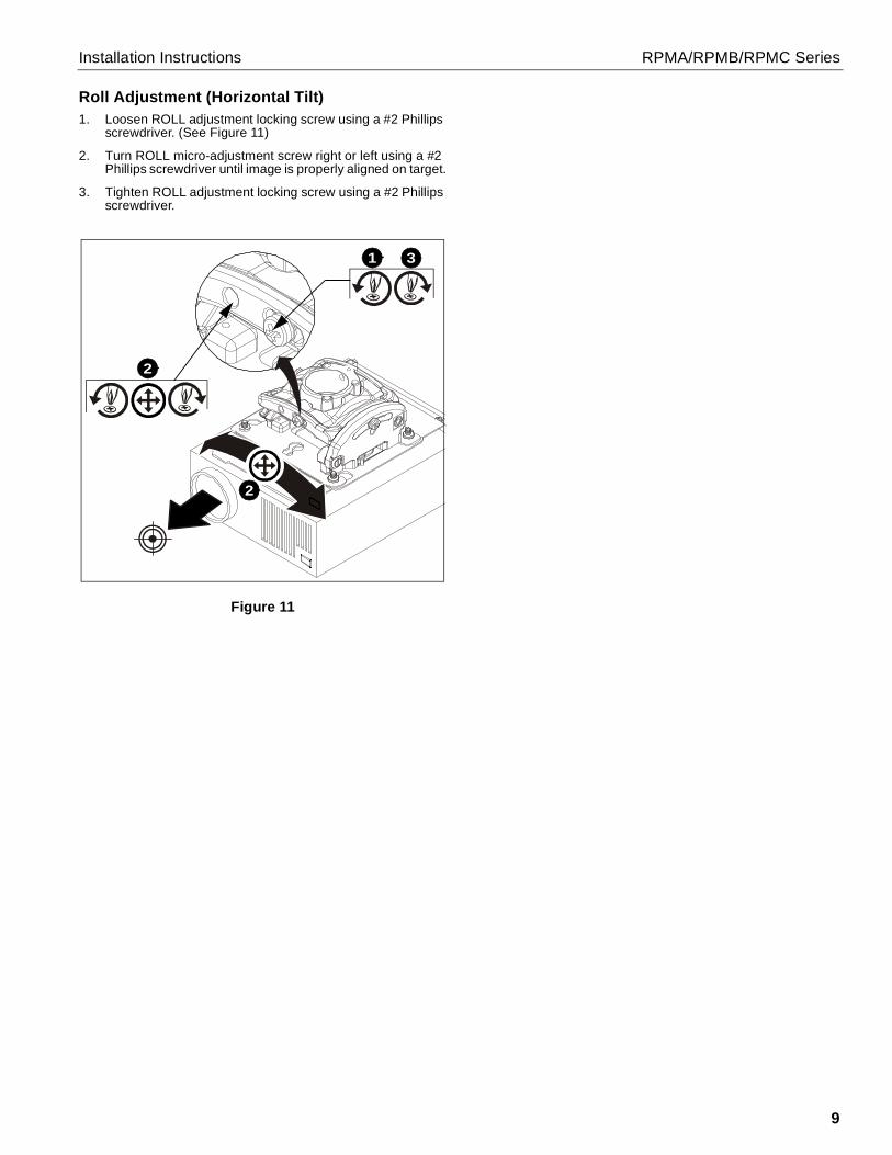
Roll Adjustment (Horizontal Tilt)1. Loosen ROLL adjustment locking screw using a #2 Phillips
screwdriver. (See Figure 11)
2. Turn ROLL micro-adjustment screw right or left using a #2Phillips screwdriver until image is properly aligned on target.
3. Tighten ROLL adjustment locking screw using a #2 Phillipsscrewdriver.
Figure 11
1
2
3
2

RPMA/RPMB/RPMC Series Installation Instructions
10

Installation Instructions RPMA/RPMB/RPMC Series
11
USA/International A 6436 City West Parkway, Eden Prairie, MN 55344P 800.582.6480 / 952.225.6000F 877.894.6918 / 952.894.6918
Europe A Franklinstraat 14, 6003 DK Weert, NetherlandsP +31 (0) 495 580 852F +31 (0) 495 580 845
Asia Pacific A Office No. 918 on 9/F, Shatin Galleria18-24 Shan Mei StreetFotan, Shatin, Hong Kong
P 852 2145 4099F 852 2145 4477
RPMA/RPMB/RPMC Series Installation Instructions
Chief, a products division ofMilestone AV Technologies
8800-002642 Rev022018 Milestone AV Technologies
www.milestone.com01/18


![portada [Modo de compatibilidad] - cdn.manomano.fr · instrucciones instructions instruction instruÇÕes anweisungen instructies instruzioni ΟΔΗΓΊΕΣ ИНСТРУКЦИИ manual](https://img.pdfslide.net/doc/110x75/5ba671c709d3f263508bb26a/portada-modo-de-compatibilidad-cdn-instrucciones-instructions-instruction.jpg)