Embed Size (px)
Citation preview

Instruction and Assembly ManualVersion 1.1 (Jan 2018)
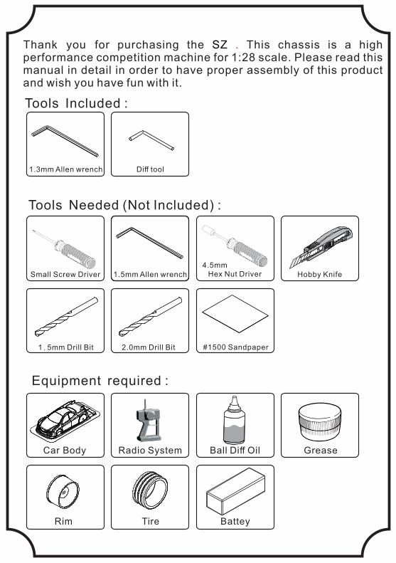
Tools Needed (Not Included) :
Equipment required :
Tools Included :
Thank you for purchasing the This chassis is a high SZ . performance competition machine for 1:28 scale. Please read this manual in detail in order to have proper assembly of this product and wish you have fun with it.
Car Body Radio System Ball Diff Oil Grease
Rim Tire Battey
Small Screw Driver 1.5mm Allen wrench
1.3mm Allen wrench Diff tool
Hex Nut Driver4.5mm
Hobby Knife
1.5mm Drill Bit 2.0mm Drill Bit #1500 Sandpaper
P.1
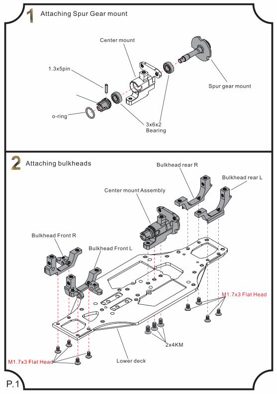
Attaching Spur Gear mount
Attaching bulkheads
3x6x2Bearing
o-ring
1.3x5pin
2x4KM
M1.7x3 Flat Head
M1.7x3 Flat Head
Lower deck
Bulkhead rear L
Bulkhead rear R
Bulkhead Front R
Bulkhead Front L
Center mount Assembly
Center mount
Spur gear mount
Loosen
Tighten
After assembly
Diff tool
P.2
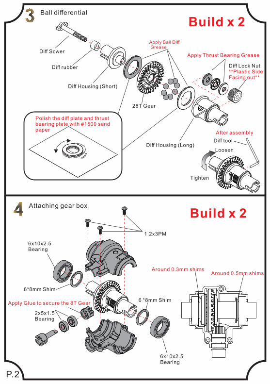
Ball differential
Polish the diff plate and thrust bearing plate with #1500 sand paper
Apply Ball Diff Grease
Apply Thrust Bearing Grease
Diff Housing (Long)
28T Gear
Diff Housing (Short)
Diff rubber
Diff Scwer
Diff Lock Nut**Plastic Side Facing out**
Attaching gear box
Build x 2
6x10x2.5Bearing
6x10x2.5Bearing
1.2x3PM
6 *8mm Shim
6*8mm Shim
2x5x1.5Bearing
Around 0.3mm shimsAround 0.5mm shims
Build x 2
Apply Glue to secure the 8T Gear
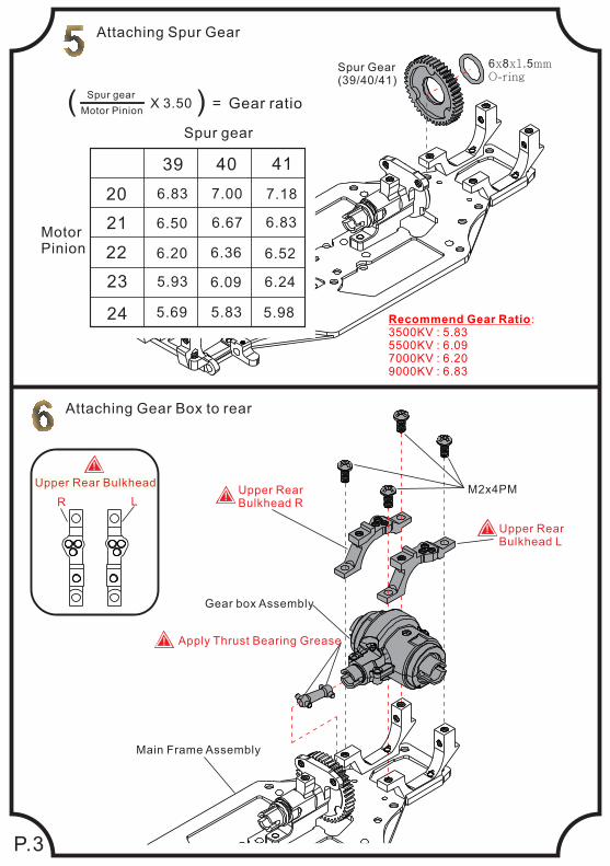
Attaching Spur Gear
P.3
Attaching Gear Box to rear
Gear box Assembly
Spur Gear(39/40/41)
6x8x1.5mmO-ring
Upper Rear Bulkhead L
!
Upper Rear Bulkhead R
!M2x4PM
Main Frame Assembly
Upper Rear Bulkhead
LR
!
20
21
22
23
24
39 40 41
6.83 7.00 7.18
6.50 6.67 6.83
6.20 6.36 6.52
5.93 6.09 6.24
5.69 5.83 5.98
MotorPinion
Spur gear
Gear ratio( ) =X 3.50Motor Pinion
Spur gear
Recommend Gear Ratio: 3500KV : 5.835500KV : 6.097000KV : 6.209000KV : 6.83
Apply Thrust Bearing Grease!
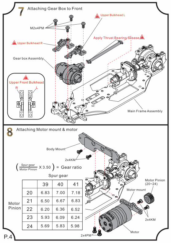
20
21
22
23
24
39 40 41
6.83 7.00 7.18
6.50 6.67 6.83
6.20 6.36 6.52
5.93 6.09 6.24
5.69 5.83 5.98
MotorPinion
Spur gear
Gear ratio( ) =X 3.50Motor Pinion
Spur gear
P.4
Attaching Gear Box to Front
Gear box Assembly
Main Frame Assembly
M2x4PM
Upper Bulkhead R!
Upper Bulkhead L!
Upper Front Bulkhead
LR
!
Attaching Motor mount & motor
Motor Pinion(20~24)
2x4PM
2x4KM
2x4KM
Motor
Motor mount
Body Mount
Apply Thrust Bearing Grease !
P.5
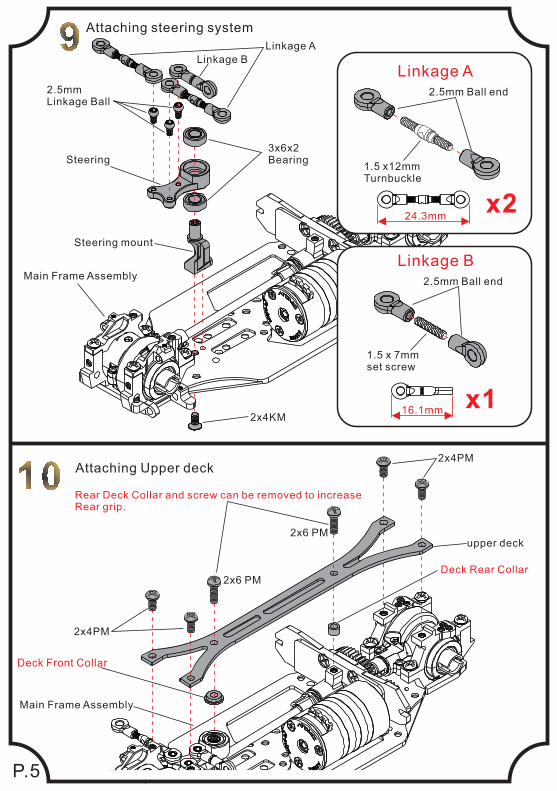
x2
2.5mm Ball end
1.5 x12mmTurnbuckle
Linkage A
24.3mm
x1
2.5mm Ball end
16.1mm
1.5 x 7mmset screw
Linkage B
Attaching steering system
Linkage B
Linkage A
2.5mmLinkage Ball
3x6x2BearingSteering
Steering mount
Main Frame Assembly
2x4KM
Attaching Upper deck
2x4PM
2x4PM
2x6 PM
upper deck
Main Frame Assembly
Deck Front Collar
Deck Rear Collar
Rear Deck Collar and screw can be removed to increase Rear grip.
2x6 PM
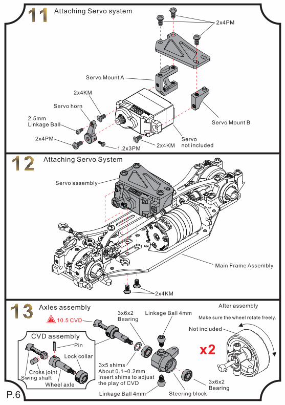
After assembly
Make sure the wheel rotate freely.
Not included
P.6
Attaching Servo system
Servo Mount A
Servo Mount B
Servo not included
Servo horn
2.5mmLinkage Ball
2x4PM
2x4KM
2x4KM1.2x3PM
2x4PM
Servo assembly
2x4KM
Main Frame Assembly
Attaching Servo System
Axles assembly
x2CVD assembly
Lock collar
Wheel axle
Cross jointSwing shaft
Pin
Insert shims to adjustthe play of CVD
10.5 CVD!
3x5 shimsAbout 0.1~0.2mm
3x6x2Bearing
3x6x2Bearing
Steering blockLinkage Ball 4mm
Linkage Ball 4mm
oil
P.7
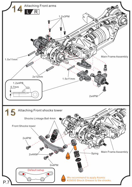
Attaching Front arms
L R
0.7mm
1.2x4PB
Default setup
Attaching Front shocks tower
oilWe recommend to apply Atomic#25000 Shock Grease to the shocks.
Sping2x4KM
2x4PM
2x4PM
Front Shocks tower
Shocks Linkage Ball 4mm
1.5x11mm2x12mm
1.5x11mm
2x4PM
1.2x3PM
Main Frame Assembly
Main Frame Assembly
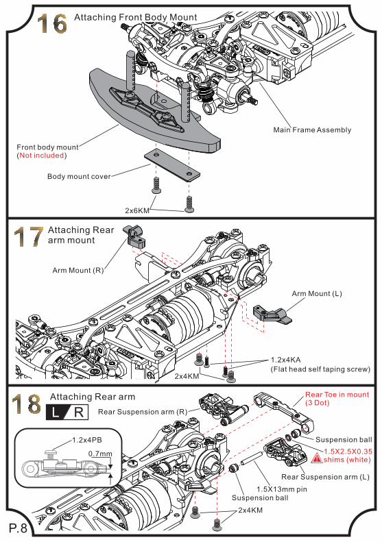
Attaching Front Body Mount
2x6KM
Body mount cover
Front body mount( )Not included
Main Frame Assembly
2x4KM
1.2x4KA
(Flat head self taping screw)
2x4KM
0.7mm
1.2x4PB
L R
Attaching Rear arm Rear Toe in mount(3 Dot)
Suspension ball
1.5X13mm pinSuspension ball
Rear Suspension arm (R)
Rear Suspension arm (L)
1.5X2.5X0.35shims (white)!
Attaching Rear arm mount
Arm Mount (L)
Arm Mount (R)
P.8
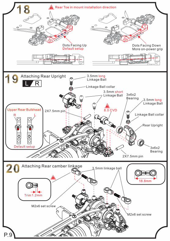
P.9
Dots Facing Up Dots Facing DownMore on-power grip
Rear Toe in mount installation direction
Default setup
!
3.5mm longLinkage Ball
L R
Attaching Rear Upright
Linkage Ball collar
2X7.5mm pin
3.5mm shortLinkage Ball 3x6x2
Bearing
Rear Upright
3.5mm longLinkage Ball
Linkage Ball collar
3x6x2Bearing
2X7.5mm pin
8.0 CVD
!
Default setup
Upper Rear Bulkhead
LR
Attaching Rear camber linkage
18.8mm
1.2mmTrim
!
M2x6 set screw
M2x6 set screw
3.5mm linkage ball
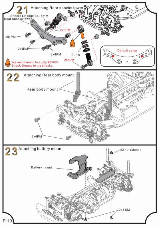
P.10
Attaching Rear shocks tower
Default setup
oilWe recommend to apply #25000Shock Grease to the shocks.
Sping
oil
Shocks Linkage Ball 4mm
2x4PM
2x4KM
2x4PM
Rear Shocks tower
Attaching Rear body mount
Rear body mount
2x4PM
Attaching battery mount
2x4 KM
M2 nut (Metal)
2x6PM
2x6PM
Battery mount
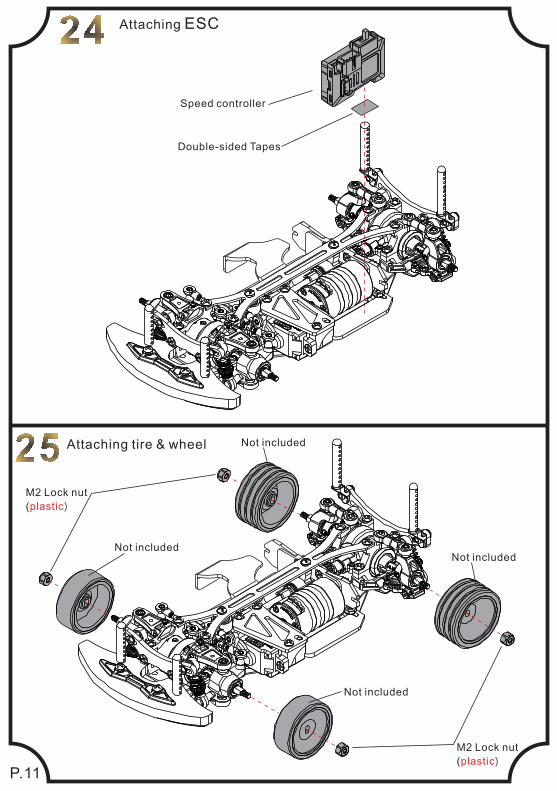
P.11
M2 Lock nut
( )plastic
M2 Lock nut
( )plastic
Not included
Not includedNot included
Not includedAttaching tire & wheel
Attaching ESC
Speed controller
Double-sided Tapes
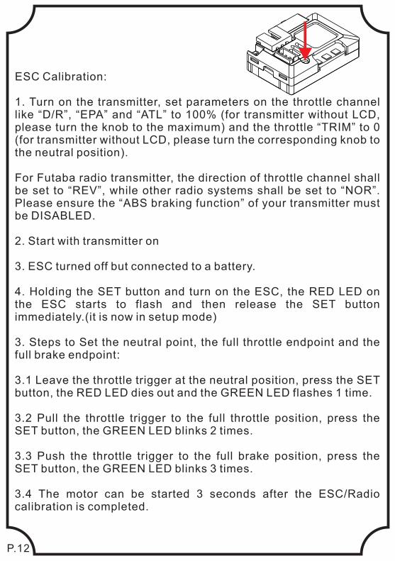
ESC Calibration:
1. Turn on the transmitter, set parameters on the throttle channel like “D/R”, “EPA” and “ATL” to 100% (for transmitter without LCD, please turn the knob to the maximum) and the throttle “TRIM” to 0 (for transmitter without LCD, please turn the corresponding knob to the neutral position).
For Futaba radio transmitter, the direction of throttle channel shall be set to “REV”, while other radio systems shall be set to “NOR”. Please ensure the “ABS braking function” of your transmitter must be DISABLED.
2. Start with transmitter on
3. ESC turned off but connected to a battery.
4. Holding the SET button and turn on the ESC, the RED LED on the ESC starts to flash and then release the SET button immediately.(it is now in setup mode)
3. Steps to Set the neutral point, the full throttle endpoint and the full brake endpoint: 3.1 Leave the throttle trigger at the neutral position, press the SET button, the RED LED dies out and the GREEN LED flashes 1 time. 3.2 Pull the throttle trigger to the full throttle position, press the SET button, the GREEN LED blinks 2 times.
3.3 Push the throttle trigger to the full brake position, press the SET button, the GREEN LED blinks 3 times.
3.4 The motor can be started 3 seconds after the ESC/Radio calibration is completed.
P.12
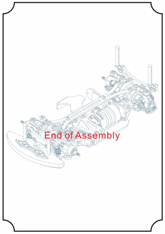
End of Assembly