Embed Size (px)
Citation preview
PMC 172
INSTRUCTION AND PARTS MANUAL
PLANETARY HYDRAULIC WINCH
READ THIS MANUAL BEFORE INSTALLING, OPERATING OR SERVICINGTHIS PRODUCT. THIS MANUAL CONTAINS IMPORTANT INFORMATION.MAKE THIS MANUAL AVAILABLE TO ALL PERSONS RESPONSIBLEFOR THE OPERATION, INSTALLATION, SERVICING AND MAINTENANCEOF THIS PRODUCT.
051117

Effective 1/1/2002
SUPERSEDES ALL PRIOR WARRANTIES
Seller warrants that each article sold under this order shall at the time of shipment (i) conform to applicablespecifications, and (ii) be free from defects in material and workmanship during normal and ordinary use andservice (the “Warranty”).
Buyer’s exclusive remedy and Seller’s sole obligation under this Warranty shall be, at Seller’s option, to repair orreplace any article or part thereof which has proven to be defective, or to refund the purchase price of such articleor part thereof.
This Warranty shall expire one (1) year from the date the article is first shipped by Seller. Notice of claimed breachof this Warranty must be given by Buyer to Seller within the applicable period. Such notice shall include anexplanation of the claimed warranty defect and proof of date of purchase of the article or part thereof for whichwarranty coverage is sought. No allowances shall be made by Seller for any transportation, labor charges, parts,“in and out” costs, adjustments or repairs, or any other work, unless such items are authorized in writing and inadvance by Seller. Nor shall Seller have any obligation to repair or replace items which by their nature areexpendable.
If an article is claimed to be defective in material or workmanship, or not to conform to the applicable specifications,Seller will either examine the article at Seller’s site or issue shipping instructions for return to Seller. This Warrantyshall not extend to any articles or parts thereof which have been installed, used, or serviced otherwise than inconformity with Seller’s applicable specifications, manuals, bulletins, or instructions, or which shall have beensubjected to improper installation, operation, or usage, misapplication, neglect, overloading, or employment forother than normal and ordinary use and service.
This Warranty shall not apply to any articles or parts thereof furnished by Seller to Buyer’s specifications and/orfurnished by Buyer or acquired from others at Buyer’s request.
SELLER MAKES NO EXPRESS WARRANTIES AND NO IMPLIED WARRANTIES OF ANY KIND, OTHER THANTHE WARRANTY EXPRESSLY SET FORTH ABOVE. SUCH WARRANTY IS EXCLUSIVE AND IS MADE ANDACCEPTED IN LIEU OF ANY AND ALL OTHER WARRANTIES, EXPRESS OR IMPLIED, INCLUDING WITHOUTLIMITATION THE IMPLIED WARRANTIES OF MERCHANTABILITY AND FITNESS FOR A PARTICULARPURPOSE.
The remedies for this Warranty shall be only those expressly set forth above, to the exclusion of any and all otherremedies of whatsoever kind. The limited remedies set forth above shall be deemed exclusive, even though theymay fail their essential purpose. No agreement varying or extending the foregoing Warranty, remedies, exclusions,or limitations shall be effective unless in a writing signed by an executive officer of Seller and Buyer. ThisWarranty is non-transferable.
Under no circumstances shall Seller be liable (i) for any damage or loss to any property other than the warrantedarticle or part thereof, or (ii) for any special, indirect, incidental, or consequential damage or loss, even thoughsuch expenses, damages, or losses may be foreseeable.
The foregoing limitations on Seller’s liability in the event of breach of warranty shall also be the absolute limit ofSeller’s liability in the event of Seller’s negligence in manufacture, installation, or otherwise, with regard to thearticles covered by this Warranty, and at the expiration of the Warranty period as above stated, all such liabilitiesshall terminate.
WARNING
Note: Specifications contained in this Instruction and Parts Manual are subject to change without notice.
WARRANTY
planetary winches/drives are not designed for operations involving lifting or movingpersonnel. The WINCH CORPORATION cannot be held liable or responsible
for any accident resulting from such use of planetary winches/drives.

PAGE 1172 REV.051117
The planetary hydraulic winches are made for hoisting and lowering loads and to be operated by trained and professionalpersonnel. They are not designed for operations involving lifting or moving personnel. The winches are powered by hydraulic
in an application, they do not function as an independent machine and it is not allowed to use them as such.
The winches are to be used within the specifications as listed in the manual under “SPECIFICATIONS”. Other use as foreseen
FAILURE TO COMPLY WITH THE FOLLOWING SAFETYRECOMMENDATIONS AND LOCAL RULES ANDREGULATIONS WILL RESULT IN PROPERTY
DAMAGE, SEVERE INJURY OR DEATH.
Definition: Caution indicates a potentiallyhazardous situation which, if not avoided mayresult in minor or moderate injury.
Definition: Warning indicates a potentiallyhazardous situation which, if not avoided couldresult in death or serious injury.
Definition: Danger indicates a potentiallyhazardous situation which, if not avoided willresult in death or serious injury.
DANGER
SAFETY RECOMMENDATIONS
1. Do not install, operate or service winch beforereading and understanding manufacturer'sinstructions.
2. The winch described herein is not designed foroperations involving lifting or moving personnel.
3. Do not lift or carry loads over people.
4. Do not exceed recommended operating pressure(psi) and operating volume (gpm).
5. Do not jerk the winch. Always smoothlyaccelerate and decelerate load.
6. Do not operate a damaged, noisy ormalfunctioning winch.
7. Do not leave a load suspended for anyextended period of time.
8. Never leave a suspended load unattended.
9. Winch should be maintained and operated byqualified personnel.
10. Inspect winch, rigging, mounting bolts andhoses before each shift.
11. Warm-up equipment before operating winch,particularly at low ambient temperatures.
12. Verify winch function by raising and lowering afull test load to a safe height before each shift.
13. Do not weld any part of the winch.
14. Verify gear lubrication and brake circulationsupply and return before operating winch.
15. Be sure of equipment stability before operatingwinch.
16. Wear proper clothing to avoid entanglement inrotating machinery.
17. Always stand clear of the load.
18. Use only recommended hydraulic oil and gearlubricant.
19. Keep hydraulic system clean and free fromcontamination at all times.
20. Maintain winch and equipment in good operatingcondition. Perform scheduled maintenance regularly.
21. Keep hands clear when winding wire rope ontothe winch drum.
22. Do not use the wire rope as a ground for welding.
23. Rig the winch carefully. Ensure that the wirerope is properly anchored to the correct cable anchorslot at the cable drum.
24. Do not lift a load with a twisted, kinked ordamaged wire rope.
25. Consult wire rope manufacturer for size, typeand maintenance of wire rope.elen
26. Maintain five wraps of wire rope on the cabledrum at all times.
27. In case of a power failure or breakdown leadingto an unexpected stop of the hydraulic power circuit,stand clear of the area and the load being hoisted,take the necessary precautions to prevent access toarea where the load is halted.
28. The noise level of the winch is 83 dBA measuredon a distance of 1.00 meter, 1.60 meters high. Themeasuring equipment used was: Realistic #42-3019.
29. Clean up any oil spillage immediately.
30. Wear proper clothing and personal protectionequipment such as, footwear, safety goggles and ahard hat. Read manual first.
power. The ropes / cables for hoisting operations are not supplied by the hoist manufacturer. The winches are always assembled
in the functional description of the hydraulic winch is not allowed without written permission from the manufacturer.

PAGE 2 172 REV.950101
GENERAL DESCRIPTION:
The winch has equal speed in both directions and a freespool feature which can be operated manually orhydraulically, depending on the option. The main components of this unit are:
✛ high torque, low speed hydraulic motor✛ multi-disc brake with over-running clutch✛ planetary reduction✛ brake housing✛ cable drum✛ final drive housing✛ freespool mechanism
FUNCTION IN FORWARD ROTATION (PULLING):In forward rotation, or when the winch is pressurized for pulling, the output torque and rpm of the hydraulic motorare transmitted through the brake shaft and freespool coupling to the final sungear. The planet gears are driven bythe final sungear and cause the planet hub to drive the cable drum at a reduction of 9.25:1. When a load is pulled,an over-running clutch which connects the motor drive shaft to the automatic brake assembly, permits free rotationof the sungear, without effecting the brake. When the winch rotation is stopped, the load on the cable drum causesthe over-running clutch to lock and the load is held safely by the disc brake.
FUNCTION IN REVERSE ROTATION (PAYING OUT):In reverse rotation, or paying out of a load, hydraulic pressure from the reverse side of the hydraulic motor ischannelled to the brake piston, causing the brake piston to release the multi-disc brake. The pressure required torelease the brake is 400 - 600 psi (28 - 42 bar). The over-running clutch, connecting the motor drive shaft to the brakeassembly, locks, causing the brake discs to rotate between stationary divider plates. If the load on the cable drumincreases the pay out speed, the resulting pressure drop in the brake piston increases friction between the frictionplates and slows the drum. In this way, a completely smooth pay out speed can be achieved in a stepless operationby modulation of the winch control valve. When the control valve is returned to neutral position, rotation stops andthe disc brake applies automatically.
During pay out operations of the winch, the friction created by the brake discs results in heat. This heat is dissipatedby the circulation of hydraulic fluid from the brake housing, supplied internally through the hydraulic motor. Thiscirculation flow is internally vented to the return line through a check valve arrangement inside the specially modifiedmotor. The circulation flow is supplied only when the wire rope is payed out. A separate vent line connecting the
IMPORTANT: SAFETY VALVE
pressure in the brake housing. To indicate excessive pressure and potential damage to thehydraulic motor or to the oil seal in the brake housing, a safety valve is installed on the motoradaptor.
BREATHER RELIEF VALVEExcessive pressure in the brake housing will damage the oil seal separating the brake housing fromthe drum interior. Damage to this seal will cause the drum to fill up with hydraulic fluid. To preventdamage to the drum seal and end cover of the final drive if the cable drum fills up with hydraulicfluid, a breather relief (PARTS REFERENCE item 130) is installed on the end cover. The breatherrelief does not prevent oil seal failure but serves as an indicator or warning that the seals betweenbrake housing and the cable drum interior have failed and must be replaced immediately.
The winch is a planetary, hydraulic winch primarily intended for mobile or recovery adaptations.
DESCRIPTION
Winch with the hydraulic reservoir is not required (see TYPICAL HYDRAULIC CIRCUIT).
The winch does not require a drain line up to 100 psi permissible back

PAGE 3172 REV.950101
FUNCTION OF THE FREESPOOL MECHANISM:
MODEL R5-12-70-1MThis model has a manually actuated freespool function. The freespool feature is enabled by turning the freespoolhandle 180 degrees in a counterclockwise direction. This will disengage the final sungear from the freespool couplingand provide for a free turning drum. To re-engage the freespool coupling, turn the handle 180 degrees in a clockwisedirection.
IMPORTANT: The freespool function cannot be engaged or disengaged under load or while thecable drum is rotating.
MODEL R5-12-70-1FThis model has a hydraulically actuated freespool feature. The final sungear is pulled out of engagement with thefreespool coupling, by the freespool piston, which is spring applied and pressure released. To disengage thefreespool coupling, hydraulic pressure of 400 psi (28 bar) must be supplied to the freespool release port (seeINSTALLATION DRAWING). When the hydraulic pressure is removed, the freespool coupling will re-engage.
IMPORTANT: The freespool coupling cannot be engaged or disengaged under load or whilethe cable drum is rotating.
DESCRIPTION CONTINUED

PAGE 4
EXPLANATION OF MODEL CODING
172 REV.010215
R 5 X - XX - XX - X X - X XXXXBASIC UNIT SERIES R = Recovery winch
SIZE OF UNIT
REDUCTION RATIOOnly used for non-standard reduction ratios
TYPE OF BRAKE
-12 Automatic brake, counterclockwise drum rotation, intravent
-15 Automatic brake, clockwise drum rotation, intravent
HYDRAULIC MOTOR -70 High torque, low speed hydraulic motor, 12.9 cubic inch displacement
(Other displacements are optional)
DRUM SIZE -1 5.0 inch drum diameter X 11 3/8 inch flange diameter X 9 inch between
flanges - STANDARD
(For other drum sizes refer to APPENDIX A)
OPTIONS - F Hydraulically actuated freespooling
- M Manually actuated freespooling
DESIGN REVISION
SPECIFICATION NUMBERDescribes features not identified by preceding codes
NOTE: Clockwise and counterclockwise drum rotation is the direction of rotation for pulling or hoisting,established by looking at the hydraulic motor.

PAGE 5
OPTIONS
172 REV.950101
CLOCKWISE ROTATION:
looking at the hydraulic motor of the winch. Drum rotation for clockwise hoisting direction is available as an option.
CABLE DRUM SIZES:Refer to APPENDIX A for optional cable drum sizes and specifications.
OPTIONAL HYDRAULIC GEAR MOTOR:
hydraulic motor with a displacement of 12.9 cubic inches. The performance of the winch can be changed by usingmotors with different displacements.
(Contact the factory for performance information if using motors with different displacements.)
The drum rotation of the standard planetary winch is counterclockwise for pulling when
The performance of the standard planetary winch is based on a NICHOLS Series 110 IGR

PAGE 6
SPECIFICATIONS
172 REV.030429
Performance specifications are based on standard hydraulic motor, gear ratio and cable drum with 1/2 inch diameterwire rope. For other cable drums refer to APPENDIX A. Performance specifications for winches supplied withoptional motors are provided in attached supplement.
CABLE DRUM DIMENSIONS (STANDARD DRUM):Barrel diameter 5.00 in 127 mmFlange diameter 11.38 in 289 mmBarrel length 9.00 in 229 mm
CABLE STORAGE CAPACITY:(Size of wire rope) 3/16 in 1394 ft 425 m
1/4 in 732 ft 223 m5/16 in 481 ft 147 m3/8 in 337 ft 103 m
7/16 in 268 ft 82 m1/2 in 209 ft 64 m
9/16 in 160 ft 49 m
MAXIMUM OPERATING PRESSURE: 2350 psi 162 bar
MAXIMUM OPERATING VOLUME: 15 (US) gpm 57 l/min
MINIMUM OPERATING VOLUME: 5 (US) gpm 19 l/min
DRUM TORQUE AT MAXIMUM PRESSURE: 30,305 lb-in 3,424 Nm
DRUM RPM AT MAXIMUM VOLUME: 26 rpm
LINE PULL AT MAXIMUM PRESSURE:Bare drum 11,020 lb 49.0 kN
Full drum 5,573 lb 24.8 kN
LINE SPEED AT MAXIMUM VOLUME:Bare drum 37 fpm 11 m/min Full drum 74 fpm 23 m/min
PERMISSIBLE SYSTEM BACK PRESSUREAT MOTOR RETURN PORT: 100 psi 6.9 bar
LUBRICATING OIL: Refer to RECOMMENDATIONS for viscosity and instructions.Refer to APPENDIX A for oil volume required.

PAGE 7172REV.950101
PERFORMANCE GRAPHSPG-R5
LINE PULL VS. OIL PRESSURE:
LINE SPEED VS. OIL VOLUME:
Performance graphs are based on standard hydraulic motor and cable drum with 1/2 inch diameterwire rope.
2000
2500
1500
1000
500
0
15
12
9
6
3
0
1102088166612440822040
0 1000 2000 3000 4000 5000
176
141
105
70
35
0
LINE PULL
lb.
kg.
OIL
PR
ES
SU
RE
PS
I
OIL
PR
ES
SU
RE
kg/cm
2
160 33 49 66 82
0 5 10 15 20 25
0fpm
m/min
LINE SPEED
11
23
34
45
57
OIL
VO
LU
ME
GP
M (
US
)
OIL
VO
LU
ME
LIT
ER
S/M
IN
FULL D
RUM
MEAN DRUM
BARE DRUM
BARE DRUM
MEAN DRUM
FULL DRUM
PAGE 8
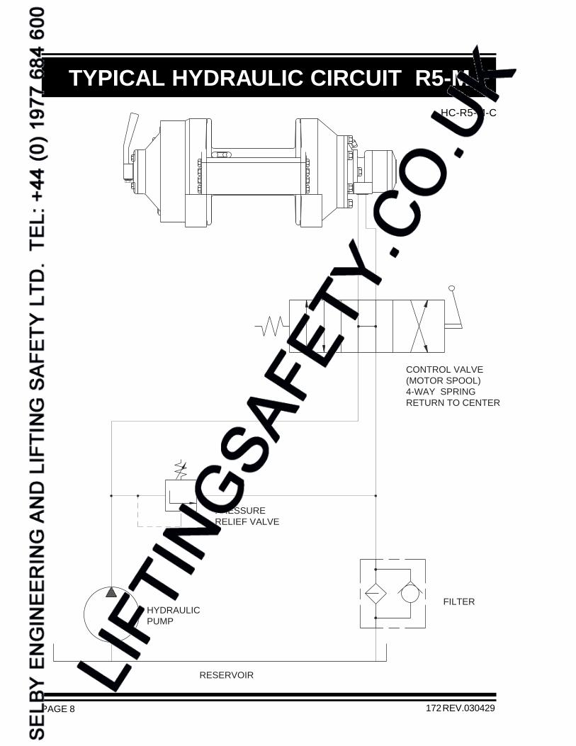
TYPICAL HYDRAULIC CIRCUIT R5-MHC-R5-M-C
172 REV.030429
PRESSURERELIEF VALVE
CONTROL VALVE(MOTOR SPOOL)4-WAY SPRINGRETURN TO CENTER
RESERVOIR
HYDRAULICPUMP
FILTER

PAGE 9172 REV.030429
TYPICAL HYDRAULIC CIRCUIT R5-FHC-R5-F-C
PRESSURERELIEF VALVE
RESERVOIR
HYDRAULICPUMP
FILTER
400 PSI (28 BAR)PRESSURE REQUIREDFOR FREESPOOL CONTROL VALVE
(MOTOR SPOOL)4-WAY SPRINGRETURN TO CENTER

PAGE 10 172 REV.030429
RECOMMENDATIONS
HYDRAULIC FLUID:
planetary winches should be a high grade, petroleumbased fluid, with rust, oxidation and wear resistance.Fluid cleanliness and operating viscosity are critical towinch reliability, efficiency and service life.
For optimum performance, the recommended viscosityrange at operating temperature is 81 - 167 SUS (16 - 36CS). For extreme operating conditions of short duration,the maximum viscosity range of 58 - 4635 SUS (10 -1000 CS) should not be exceeded.
For optimum performance, the winch recommendedhydraulic fluid temperature operating range is 80 - 150F(27 - 66 C). For extreme operating conditions of shortduration, the maximum temperature range of -5 - 180F(-21 - 82 C) should not be exceeded.
LUBRICATION:The winch gear train requires oil bath lubrication. Thewinch is shipped from the factory without lubricating oil.
IMPORTANT: ADD LUBRICATING OIL BEFORE RUNNING WINCH.
Refer to INSTALLATION DRAWING for location oflubricating oil fill port. Refer to APPENDIX A for quantityof oil required. For normal operating temperatures useSAE 90 lubricating oil. Consult lubricating oil supplier orfactory for temperature beyond normal operating range.
HYDRAULIC PUMP:
planetary winch, the hydraulic pump must supply themaximum flow of hydraulic fluid at the hydraulic pressurestated in SPECIFICATIONS.
HYDRAULIC CONTROL VALVE:The standard control valve used for operation of the
spring return to neutral feature, which provides for openflow from the pressure ports of the winch to the reservoirin neutral position of the control (motor spool). It isimportant to point out that good speed control, especiallywhen lowering a load, depends on the "metering"characteristics of the control valve. The better the oilflow is "metered" the better will be the speed control.
HYDRAULIC PRESSURE RELIEF:
winch requires a pressure relief set at the operatingpressure (see SPECIFICATIONS). Usually, a pressurerelief is part of the hydraulic control valve. Where this isnot the case, a separate pressure relief valve must beinstalled and set at the recommended maximum pressure.
HYDRAULIC RESERVOIR:It is recommended that the hydraulic reservoir hassufficient capacity to provide good heat dissipation inorder to prevent over-heating of the hydraulic fluid. Thehydraulic reservoir should be made from clean andscale-free material to prevent contamination of thehydraulic fluid. In order to prevent air from being mixedwith the hydraulic fluid, the reservoir should have anover-flow baffle separating the return lines from thesuction line and all return lines should enter the reservoirbelow the fluid level. The reservoir should be mountedclose to and above the hydraulic pump in a locationwhich provides for free air circulation around the reservoir.
HYDRAULIC HOSES:The following hydraulic hoses are recommended for
planetary winch:
Pressure lines: Equivalent to SAE 100R12-12Hydraulic freespool line: Equivalent to SAE 100R3-3
It is recommended that a larger size of hydraulic hose isinstalled where the pressure lines or the circulation linesare excessively long.
HYDRAULIC FILTER:Hydraulic filter recommendations for the hydraulic circuit
line filter, are given as follows:
Average atmosphere: 10 micronsDusty atmosphere: 5 microns
In order to prevent accidental stoppage of the return lineflow, the oil filter should have a by-pass feature.
USE OF AN E STOP:The use of an E stop (emergency) is mandatory in thecontrols circuit, the E stop is to be placed in theoperators control panel. The E stop has to be designedand placed in line with EN 60204 and EN 418.
For maximum performance of the
planetary winch must have a four-way,
maximum efficiency of the
of the planetary winch, based on a return
The hydraulic fluid selected for use with The hydraulic circuit for the planetary

PAGE 11
INSTALLATION INSTRUCTIONS
FAILURE TO FOLLOW INSTALLATION INSTRUCTIONS COULDRESULT IN PROPERTY DAMAGE, SEVERE INJURY OR DEATH.
DANGER
172 REV.030429
and performance. If the winch is mounted to an uneven surface, the centre line of the unit can be distorted to a pointwhere the winch will not operate in either direction. It is therefore very important that the following instructions are
1) Make certain that the mounting platform is sufficiently strong in order to avoid deflection when a load is lifted.
2) Set the winch on the mounting platform and check for surface contact on all mounting pads of the winch.
3) If there is a space between the mounting surface and one of the mounting pads, the mounting surface is noteven and the space below the mounting pad must be shimmed. If this condition exists, proceed as follows:
a) Install mounting bolts snug tight on the three mounting pads which are in contact with the mounting surface.(For mounting bolt size and grade see INSTALLATION DRAWING.)
b) Measure the space underneath the fourth mounting pad with a feeler gauge and use shim stock of equivalentthickness in the space between the mounting pad and the mounting surface.
c) Only after this procedure should the fourth mounting bolt be installed. Tighten all four bolts per BOLTTORQUE CHART.
4) Fill the winch with lubricating oil. (See APPENDIX A for oil volume required.)
5) Use recommended circuit components and hydraulic hoses.
6) The circulation return line of the winch should be plumbed in such a manner that the brake housing remainsfull of oil at all times. Connect the return line directly to reservoir. Do not connect to a common return line.
7) Verify that breather relief, item 130, is in place on end cover above oil level. End cover may need to be rotatedif winch is not installed upright.
IMPORTANT: Do not replace breather relief or safety valve with a pipe plug. The breather relief doesnot prevent oil seal failure but serves as an indicator or warning that the oil sealsbetween brake housing and the cable drum interior have failed and must be replacedimmediately. The safety valve acts as a warning that excessive pressure is presentin the brake housing and must be rectified immediately.
The initial installation or mounting of a planetary winch is critically important for proper operation
observed when a planetary winch is installed:

PAGE 12
OPERATING INSTRUCTIONS
FAILURE TO FOLLOW OPERATING INSTRUCTIONS COULDRESULT IN PROPERTY DAMAGE, SEVERE INJURY OR DEATH.
SI1013-R5
DANGER
172 REV.051117
WIRE ROPE INSTALLATIONCounterclockwise pulling winch shown.(Use cable anchor slot on opposite side of drum for clockwise pulling winch.)
Feed the wire rope through the cableanchor slot. Loop rope back into slotas shown. Insert cable anchor intoslot, small end first and long sidenearest the drum flange. Pull ropetight to wedge rope in slot.
2) On wire rope installation, care must be taken that the wire rope is wrapped completely around the cable anchorand properly pulled into the cable anchor slot in the cable drum. The cable drum requires 5 wraps of wire ropefor safety.
3) The winch operation is controlled by a single control valve lever which has a forward , a reverse and a neutralposition. Speed control in either direction is obtained by modulation of the control valve lever. Maximum linespeed in either direction is obtained when the control valve lever is moved as far as it can go. The disc brakeof the winch will come on automatically when the winch control lever is returned to neutral .
4) Always warm up equipment prior to operating winch, particularly in low ambient temperature. Circulate hydraulicoil through the winch control valve for several minutes to warm the hydraulic system. To prime the winch withwarm oil, operate the winch at slow speed, forward and reverse, several times.
5) Prevent corrosion damage to winch interior. If not used regularly, run winch up and down at least once everytwo weeks.
6) To ensure proper winch installation and function, raise and lower a full test load to a safe height before usingwinch for regular operation at the start of each shift.
If, after a new installation, the winch does not function properly, refer to the TROUBLESHOOTING section ofthis manual.
the wire rope can be fastened to the cable drum.
for counterclockwise pulling. Standard rotation for pulling is counterclockwise when looking at the hydraulicmotor of the unit. It is critical to select the cable anchor slot which will permit winding of the wire rope on thedrum in the correct direction of rotation. If the wire rope is wound on the cable drum in the wrong direction ofrotation, the winch will have no braking capacity. Each winch is shipped from the factory with a label on thedrum indicating the correct cable anchor slot.
The ropes, chains, slings, etc. are not part of the winch and are not covered by this manual. Referto manufacturer’s handling, inspection and maintenance recommendations to avoid potentialaccidents. For selection of ropes, etc. please check following product standards: DIN 15020,prEN818-1/9, prEN 1492-1/2, prEN 1677-1/3 and other relevant product standards.
IMPORTANT:
CABLE ANCHOR
CABLE ANCHOR SLOT
After the planetary winch has been installed in accordance with the INSTALLATION INSTRUCTIONS,
1) The cable drum of the planetary winch has two cable anchor slots, one for clockwise and one

PAGE 13
TROUBLE SHOOTING
FAILURE PROBABLE CAUSE
172 REV.950101
Winch will not produce line pull at maximumpressure as listed in SPECIFICATIONS.
GENERAL:In most cases, when the hydraulic winch does not perform satisfactorily, the cause of malfunction is foundsomewhere in the hydraulic circuit. Before the winch is removed from its mounting and disassembled, all of thehydraulic circuit components should be checked for proper function.
IMPORTANT:The hydraulic oil volume relates to the line speed or rpm of the winch.Therefore, if the winch does not produce the maximum rated line speed, a loss of hydraulic flow somewhere inthe hydraulic circuit system can be analysed. If this condition exists, install a flow meter into the hydraulic circuitto check the volume supplied to the motor ports when the winch control is completely opened. The flow metershould indicate the maximum operating volume. If the test described indicates a loss of hydraulic flow, checkthe hydraulic pump, the relief valve and the control valve.
The hydraulic pressure relates to the line pull or lifting capacity of the winch.If the winch will not pull the maximum rated load, install a pressure gauge into the pressure line leading to thepulling port on the hydraulic winch motor. Stall the winch to prevent rotation of the drum and then open the controlvalve and check the hydraulic pressure reading of the installed pressure gauge. If the pressure reads below thespecified maximum operating pressure, look for trouble in the hydraulic pump, the relief valve and the controlvalve. When checking oil pressure of oil volume anywhere in the hydraulic system, make certain that the hydraulicpump is running at maximum operating rpm. Installations using a belt drive for hydraulic pump must be checkedfor belt slippage. Verify that hydraulic reservoir is filled to the top level.
Only if the hydraulic system has been checked and found to be in order, use the following indications for probablecauses of failure in the winch:
a) Winch is mounted to an uneven surface (seeINSTALLATION INSTRUCTIONS).
b) Cable sheaves or block purchase operated with thewinch are not turning freely.
c) Damage or wear in the hydraulic motor.d) Excessive back pressure in the hydraulic system.e) Relief valve may be set too low.
a) Winch is mounted to an uneven surface (seeINSTALLATION INSTRUCTIONS).
b) Cable sheaves or block purchase operated with thewinch are not turning freely.
c) Damage or wear in the hydraulic motord) Excessive back pressure in the hydraulic circuit.
a) Leakage out of the brake piston prevents the brakefrom being released against the brake springs. This iscaused by damaged O-ring seals on the brake piston.
b) The O-ring seals, on the brake release channel betweenthe motor adaptor and the brake housing is damaged.If this failure occurs there will be substantial leakagefrom between the motor adaptor and brake housing.
c) Insufficient hydraulic pressure (see SPECIFICATIONSfor minimum operating pressure).
d) Winch is mounted to an uneven surface (seeINSTALLATION INSTRUCTIONS).
e) Hydraulic pressure is not reaching the brake piston(plugged brake release orifice in the brake housing).
Winch will not produce line speed at maximumvolume as listed in SPECIFICATIONS.
Winch will not reverse.

PAGE 14
TROUBLE SHOOTING
FAILURE PROBABLE CAUSE
172 REV.950101
a) Friction plates or divider plates have been damaged bycontamination in the hydraulic fluid, or lack of circulationflow in the brake housing.
b) Brake piston is seized in the brake housing because ofcontamination in the hydraulic fluid.
c) Excessive back pressure in the return line causes thebrake to be released.
d) Control valve has incorrect spool, which traps hydraulicpressure in the brake piston when the control valve handleis returned to neutral position. For proper function of theautomatic brake, both pressure ports of the winch must beopen to the reservoir in neutral position of the control valve.
e) Wire rope is fastened to the incorrect cable anchor slot.f) Sprag clutch is damaged or surfaces where sprag clutch
engages on motor drive shaft or brake hub are worn orindented.
g) Winch supplied with external brake release option is notplumbed per HYDRAULIC CIRCUIT. Failure to vent externalbrake release port to reservoir may trap pressure andcause winch brake to slip.
a) Pump is too slow. Pump rpm must be maintained atnormal operating speed when a load is lowered.
b) Brake is running too hot. This is caused by a complete lackof, or insufficient circulation flow. To check circulationflow, remove safety valve from motor adaptor. When winchis reversed, oil flow should be approximately 2.5 (US) gpm(9 liter/min).
c) Control valve has poor metering characteristics.d) Damaged brake plates or divider plates.e) The over-running clutch, which connects the motor shaft
with the brake assembly, is damaged.f) Air mixed with hydraulic oil (foamy oil).
a) Oil leaks from the hydraulic motor flange and the motoradaptor are caused by damaged O-ring seals.
b) Oil leaks occurring between the cable drum flanges andhousings are caused by excessive pressure in the brakehousing. Excessive pressure will damage the oil sealwhich separates the brake housing from the cable druminterior.
c) If the breather relief on the end cover leaks, the sealbetween the drum interior and the brake housing is damagedand must be replaced. This condition is caused by excessivepressure in the brake housing of the winch, operation withthe incorrect hydraulic fluid during cold weather, or arestriction in the circulation return line leading back to tank.
Brake will not hold.
Brake vibrates when lowering a load.
Oil leaks.
Refer to the SERVICE INSTRUCTIONS if it becomes necessary to disassemble the Model R5 winch.

PAGE 15
SERVICE INSTRUCTIONS
172 REV.030429
GENERAL:
instructions should be read and understood.
It is suggested that all expendable parts, such as O-rings and oil seals are not reused on reassembly. It is thereforeimportant to have a winch seal kit (Part No. 25829), and providing the hydraulic motor has to be serviced, a motorseal kit (Part No. 25688) on hand.
A clean working area is of prime importance, similar to conditions used for service work on any other hydrauliccomponents.
All parts, as they are removed from the winch assembly, should be inspected for wear and damage. Thoroughlyclean parts before reassembly, however, do not use solvent to clean friction plates.
During reassembly, lubricate all O-rings and oil seals with grease.
In the following service instructions, reference to parts is made by numbers and shown on the applicable groupdrawings.
DISASSEMBLY
the winch.
REMOVE HYDRAULIC MOTOR ASSEMBLY:
1) Remove two capscrews item 815, and lockwashers item 817. Pull the hydraulic motor item 850, out of thewinch assembly.
2) Remove and discard O-ring item 811.
3) Remove connecting tube item 830. Remove and discard two O-rings item 831.
4) Remove two check valves item 832. Remove and discard two O-rings item 833.
The standard motor of the Model R5 is a NICHOLS Series 110 IGR hydraulic motor with 12.9 cubic inchdisplacement. If a problem is analysed to be in the hydraulic motor, we recommend that a NICHOLS dealer becontacted for parts and service.
If the hydraulic motor is disassembled, the original flange section of the motor must be re-used in order to providethe required porting to operate the automatic brake and for the circulation flow.
DISASSEMBLY OF BRAKE HOUSING ASSEMBLY:Disassemble brake housing assembly as follows:
1) Remove motor adaptor item 800, by removing six capscrews item 821, and lockwashers item 823. Allow brakesprings item 752, to expand safely by unscrewing capscrews one turn at a time.
2) Remove and discard O-ring item 707.
3) Remove eight brake springs item 752. Examine brake springs for damage and measure overall length. Overallspring length should be 1.54 inch. If any spring measures less than 1.48 inch, replace all springs as a set.
4) Pull the brake piston item 750, out of the brake housing using two 1/2 - 13NC bolts screwed into the two pullerholes in the piston and discard O-rings item 751 and item 753.
Before attempting disassembly of the planetary winch with freespool, the following
The majority of service or repair work is accomplished by disassembling the brake housing of the planetary winch. There are no special tools, adjustments or calibrations necessary to service or repair

PAGE 16
SERVICE INSTRUCTIONS CONTINUED
172 REV.030429
5) Remove pipe plug item 755, and verify that circulation hole in piston is clear and unobstructed. Re-install pipeplug item 755.
6) Thoroughly inspect the brake piston outer diameters and brake housing inner bores for scoring caused byhydraulic fluid contamination. Minor surface damage may be repaired by polishing with a fine emery cloth.
7) Remove coupling fastener item 738, from center of brake shaft item 730.
8) Pull the brake shaft item 730, and complete brake hub assembly from the brake housing.
9) Disassemble brake hub assembly by removing circlip item 727, from brake shaft item 730. Remove brake shaftfrom brake hub assembly. Remove sprag clutch aligners item 722 and item 724, and sprag clutch item 723,from brake hub.
MINOR SURFACE DEFECTS WHERE THE SPRAG CLUTCH ENGAGES THEMOTOR DRIVE SHAFT AND BRAKE HUB, WILL RESULT IN BRAKEFAILURE AND ALLOW THE LOAD TO DROP, CAUSING PROPERTYDAMAGE, SEVERE INJURY OR DEATH. THOROUGHLY INSPECTTHESE AREAS AND, IF NECESSARY, REPLACE BRAKE SHAFT,
SPRAG CLUTCH AND BRAKE HUB AS A SET.
10) Thoroughly inspect brake shaft item 730, and brake hub item 720, particularly the surfaces where the spragclutch item 723, engages. If any indentation or surface damage is detected, replace brake hub, sprag clutchand brake shaft as a set.
11) Remove the 14 divider plates item 713, together with 13 brake plates item 715, and inspect for damage or wear.Plates should not show heat discoloration. Paper material on friction plates should be intact and smooth. If anydamage is detected, replace friction and divider plates as a set. Check oil for contamination if plates are in poorcondition.
DAMAGED FRICTION OR DIVIDER PLATES WILL REDUCE BRAKINGCAPACITY AND ALLOW THE LOAD TO DROP CAUSING PROPERTYDAMAGE, SEVERE INJURY OR DEATH. DO NOT USE SOLVENT TO
CLEAN THE FRICTION PLATES. PERFORM THOROUGHINSPECTION AND, IF NECESSARY, REPLACE FRICTION
AND DIVIDER PLATES AS A SET.
12) Remove brake spacer item 712, two thrust washers item 615, and thrust bearing item 617.
13) Remove bronze washer item 706. Remove and discard oil seal item 711, and backup washer item 710.
All parts have now been removed from the brake housing and there is no need for further disassembly unless a failurehas been analysed in the final drive or freespool mechanism of the Model R5.
DISASSEMBLY OF FINAL DRIVE ASSEMBLY:If a failure occurs in the mechanism located inside the final drive housing, or the winch has to be disassembledbeyond the point described in the preceding chapter, proceed as follows:
1) Remove the drain plug item 121, from the freespool housing item 250, and drain the lubricating oil from the finaldrive assembly and the cable drum interior. In order to drain all of the oil out of the cable drum interior, the winchshould be tipped to an angle and the filler plug item 503, removed.
DANGER
DANGER
PAGE 17
SERVICE INSTRUCTIONS CONTINUED
172 REV.030429
2) After draining all lubricating oil from the final drive housing item 100, remove internal retaining ring item 124.The freespool assembly, along with the final sungear, can now be pulled out of the final drive housing and putaside. If a problem exists in the freespool assembly, skip ahead to the section titled DISASSEMBLY OFFREESPOOL ASSEMBLY.
3) Remove final planet hub assembly from final housing item 100.
4) Inspect three final planet gears item 320, for damage or wear. If it is necessary to remove planet gears, removecirclip item 311, and press planet pin item 310, out of the final planet hub item 300. Inspect needle bearing item323, and two thrust washers item 321, and replace if damaged.
All parts have now been removed from the final drive assembly. If further disassembly is required,proceed as follows:
DISASSEMBLY OF CABLE DRUM ASSEMBLY:To separate brake housing item 700, and final housing item 100, from cable drum item 500, proceed as follows:
1) Remove 16 capscrews item 971, and lockwashers item 973. Remove two tie bars item 970. Stand the winchupright on its end housing.
2) Insert two heel bars between the flange of the cable drum item 500, and the brake housing item 700, and gentlypry the brake housing out of spherical roller bearing item 507.
3) Remove freespool coupling item 260, from brake housing. Remove O-ring item 293, from freespool couplingand discard.
4) Inspect journal bearing item 286, for excessive wear and replace if necessary.
5) Remove and discard oil seal item 515.
6) Inspect spherical roller bearing item 507, and replace if damaged.
7) Turn winch over to stand upright on the drum flange. Remove circlip item 513, from splined hub of cable drumitem 500.
8) Insert two heel bars between the drum flange and the final housing and carefully pry the cable drum out of ballbearing item 103.
9) Remove and discard oil seal item 105. If removal of ball bearing item 103, is necessary, first remove circlipitem 109.
DISASSEMBLY OF FREESPOOL ASSEMBLY:If a problem in the freespool assembly is analysed, follow instructions 1) and 2) from the sectiontitled DISASSEMBLY OF FINAL DRIVE ASSEMBLY, then proceed to the appropriate sub headingof HYDRAULIC or MANUAL FREESPOOL:
HYDRAULIC FREESPOOL (R5-X-70-1F):
1) Remove four hex capscrews item 253, and lockwashers item 255, from the end of the freespool assembly.Since the freespool spring item 280, applies pressure against the inside of the freespool cover, it isrecommended that the hex capscrews are unscrewed one turn at a time, evenly, until the spring pressure hasbeen released.
2) Discard O-ring item 257, and remove freespool spring item 280.
3) Remove the freespool piston item 264, along with the final sungear item 340, from the freespool cover anddiscard O-rings item 265 and item 277. Inspect the outside diameter of the piston and the internal diameter ofthe housing for any scoring caused by hydraulic fluid contamination. Minor surface damage may be repairedby polishing with a fine emery cloth.

PAGE 18
SERVICE INSTRUCTIONS CONTINUED
172 REV.030429
4) Inspect nylon planet hub stopper item 126, and replace if less than 0.14 inch thick. Remove and discard O-ring item 123, from outside of freespool housing.
5) To separate the final sungear item 340, from the freespool piston, remove circlip item 269. Inspect the twosplines on the end of the final sungear for wear and cracks. Replace if necessary.
6) To separate the ball bearing item 291, from the freespool piston, remove circlip item 267.
MANUAL FREESPOOL (R5-X-70-1M):
1) Remove hex head capscrew item 297, and lockwasher item 298, to allow removal of freespool handle item 254,from nut drive item 256.
2) Remove four hex head capscrews item 253, and lockwashers item 255, from seal carrier item 252. For correctpositioning of the seal carrier upon reassembly, make a chalk mark on the seal carrier and freespool housing item250. Pull the seal carrier out of the freespool housing, discard O-ring item 257, and oil seal item 299.
3) Remove index pin item 272, detent spring item 276, and spring seat item 284. Check these parts for wear andreplace if necessary.
4) Turn the nut drive item 256, to disconnect from the follower item 266. Inspect the three spring pins item 278,and replace if damaged or worn.
5) Remove circlip item 288, and pull the final sungear item 340, together with the follower and ball bearing item291, out of the freespool housing.
6) Remove circlip item 295, from the inside of the follower and pull the ball bearing, together with the final sungear,out of the follower.
7) To remove ball bearing item 291, from the final sungear, remove circlip item 269.
REASSEMBLYThoroughly clean and lubricate all parts. Use only new, well-greased O-rings and oil seals. Unless otherwisespecified, torque fasteners per BOLT TORQUE chart at back of manual.
REASSEMBLY OF FREESPOOL ASSEMBLY:
MANUAL FREESPOOL (R5-X-70-1M):
1) Press ball bearing item 291, onto final sungear item 340, and secure with circlip item 269.
2) Slide freespool follower item 266, over ball bearing item 291, and fasten between two circlips item 295.
3) Insert follower into bore of freespool housing item 250, and secure with circlip item 288.
4) Engage nut drive item 256, with freespool follower item 266, by twisting three spring pins item 278, into groovesof follower.
5) Place two spring seats item 284, together with detent springs item 276, and indexes item 272, into holes in endof nut drive item 256.
6) Press new, well-greased oil seal item 299, into seal carrier item 252.
7) Install new, well-greased O-ring item 257, onto seal carrier, and fasten onto freespool housing item 250, usingfour capscrews item 253, and lockwashers item 255. Check chalk marks for proper positioning beforetightening.
The winch has now been completely disassembled.

PAGE 19172 REV.030429
SERVICE INSTRUCTIONS CONTINUED
8) Attach freespool handle item 254, to nut drive item 256, with capscrew item 297, and lockwasher item 298.Verify handle is in PULLING position when sungear is fully extended.
9) Install new, well-greased O-ring item 123, into freespool housing item 250. Verify that planet hub stopper item126, is in place.
HYDRAULIC FREESPOOL (R5-X-70-1F):
1) Press ball bearing item 291, onto final sungear item 340, and secure with circlip item 269.
2) Slide freespool piston item 264, over ball bearing item 291, and retain with circlip item 267.
3) Install a new, well-greased O-ring item 277, into O-ring groove inside freespool housing. Install new, well-greased O-ring item 265, onto freespool piston item 264.
4) Insert final sungear item 340, through opening of freespool housing.
5) Install freespool spring in freespool piston item 264.
6) Install new, well-greased O-ring item 257, on freespool cover item 252.
7) Fasten freespool cover item 252, using four capscrews item 253, and lockwashers item 255. Tighten capscrewsone turn at a time to compress freespool spring.
REASSEMBLY OF CABLE DRUM ASSEMBLY:Reassemble cable drum assembly by reversing the disassembly procedure.
1) Press ball bearing item 103, into final housing item 100, and fasten with circlip item 109.
2) Press new, well-greased oil seal item 105, into other side of final drive housing.
3) Press final housing item 100, onto hub of cable drum item 500, and fasten with circlip item 513.
4) Turn winch over so it stands on final housing end. Press spherical roller bearing item 507, into cable drumitem 500.
5) Press new, well-greased oil seal item 515, into cable drum item 500.
6) Install new, well-greased O-ring item 293, on end of final sungear item 340, and slide final sungear throughjournal bearing item 286.
7) Place brake housing item 700, into cable drum item 500. Use 16 capscrews item 971, and lockwashers item973, to secure tie bars item 970.
REASSEMBLY OF BRAKE HOUSING ASSEMBLY:Reassemble brake housing assembly by reversing the disassembly procedure.
1) Install new backup washer item 710, and new, well-greased oil seal, item 711, in the bore of the brake housing.
2) Install bronze washer item 706. Place thrust bearing item 617, in between two thrust washers item 615, on topof bronze washer item 706.
3) Install sprag clutch item 723, in bore of brake hub item 720. Insert sprag clutch aligner item 722, into one sideof the brake hub. Insert the other sprag clutch aligner item 724, into the other side of the brake hub. Carefullyslide the brake shaft item 730, through the sprag clutch aligner item 724, into the brake hub assembly and fasteninto place by installing circlip item 727.
IMPORTANT: For proper brake function, ensure that the brake hub rotation is correct. Whenviewed from the motor end, the brake shaft of a counterclockwise pulling winchmust turn freely counterclockwise and lock in the clockwise direction.

PAGE 20 172 REV.030429
SERVICE INSTRUCTIONS CONTINUED
4) Install brake hub assembly through thrust washers item 615, engage spline with freespool coupling item 260,and fasten with coupling fastener item 738.
INCORRECT ASSEMBLY OF THE FRICTION PLATE AND DIVIDER PLATESTACK WILL REDUCE BRAKING CAPACITY AND ALLOW THE LOAD
TO DROP, CAUSING PROPERTY DAMAGE, SEVERE INJURY ORDEATH. REASSEMBLE PER INSTRUCTIONS.
5) Install brake spacer item 712, into brake housing. Starting and finishing with a divider plate, alternately install14 divider plates item 713, and 13 friction plates item 715.
6) Liberally grease O-ring item 751, and O-ring item 753, and install on the brake piston item 750.
7) Carefully insert the brake piston into the brake housing and turn the piston to line up the bore for the connectingtube item 830, with the bore in the motor item 850.
8) Install the eight brake springs item 752.
9) Install new, well-greased O-ring item 707, on motor adaptor pilot item 800.
10) Position motor adaptor with hydraulic motor mounting holes horizontal and the connecting tube holes of thepiston aligned with motor adaptor. Tighten six capscrews item 821, and lockwashers item 823, one turn at atime to evenly compress springs.
REPLACE HYDRAULIC MOTOR ASSEMBLY:1) Install new O-rings item 831, on each end of the connecting tube item 830, and apply grease liberally. Insert
the long end of the connecting tube into motor adaptor item 800.
2) Install new, well-greased O-ring item 811, on flange of the hydraulic motor, and two new, well-greased O-rings item 834, on check valves item 832.
3) Insert check valves in face of motor and fasten motor to motor adaptor using two capscrews item 815, andlockwashers item 817.
REASSEMBLY OF FINAL DRIVE ASSEMBLY:Reassemble final drive assembly by reversing the disassembly procedure.
1) Return winch to a horizontal position, standing on its mounting feet.
2) Reassemble final planet hub assembly. Press pre-greased needle bearing item 323, midway intofinal planet gear item 320. Position thrust washers item 321, on either side of planet gear andpress planet pin item 310, into the final planet hub item 300. Retain with circlip item 311.
3) Insert final planet hub assembly into final housing, so that spline interlocks with cable drum.
4) Install freespool housing item 250, in final housing item 100, being sure to align spring pin item 259, with notchin final housing.
5) Install retaining ring item 124, and pipe plugs item 121.
DANGER

PAGE 21172 REV.030429
SERVICE INSTRUCTIONS CONTINUED
IMPORTANT: Before operating the winch, add lubricating oil up to the oil level fill port on thefreespool housing. Refer to INSTALLATION INSTRUCTIONS for location offill port. Refer to APPENDIX A for oil volume required.
To ensure proper reassembly, run the winch in both directions without load.
PULLING A LOAD WITH A NEWLY SERVICED WINCH WILL ENABLE ANINSTALLATION OR SERVICE PROBLEM TO GO UNDETECTED AND WILL ALLOW
THE LOAD TO DROP CAUSING PROPERTY DAMAGE, SEVERE INJURY ORDEATH. TO ENSURE PROPER REINSTALLATION, REFER TOPROCEDURES AND TESTS DESCRIBED IN "INSTALLATION"
AND "OPERATING INSTRUCTIONS".
DANGER

PAGE 22
RECOMMENDED MAINTENANCE
172 REV.030429
Winch gear train lubricating oil should be changed after the initial six months or 50 hours of operation,whichever comes first. Lubricating oil should then be changed every 12 months or 500 operating hours,whichever comes first.
Hydraulic system fluid should be changed at least once every 12 months.
For optimum performance over an extended period of time, the following preventative maintenance serviceshould be done every 12 months or 500 hours, whichever comes first:
1) Disconnect all hydraulic hoses and remove the winch from its mounting.
2) Disassemble the winch as per instructions.
3) Discard and replace all O-rings and oil seals.
4) Inspect all parts for wear and replace if necessary.
5) Clean all parts and inspect for wear and damage as per instructions. Replace worn ordamaged parts as required.
6) Follow INSTALLATION and OPERATING INSTRUCTIONS when returning winch to its mounting.
and serial number of the unit.
MODEL NO. _________________
SERIAL NO. _________________
When ordering parts for the planetary winch, always quote the complete model

PAGE 23172 REV.051117
INSTALLATION DRAWING
I1061-C
FIL
LER
PO
RT
3/8-
18N
PT
(LO
CA
TE
D E
ITH
ER
ON
BA
RR
EL
OR
INC
AB
LE A
NC
HO
R P
OC
KE
T)
ST
AN
DA
RD
CA
BLE
AN
CH
OR
#23
409
GO
OD
FO
R 3
/8"
TO
9/1
6" D
IA W
IRE
RO
PE
[208
]8.
2
29.2
[742
] MO
DE
L R
5-F
29.6
[753
] MO
DE
L R
5-M
[294
]11
.6
[259
]10
.2
[222
]8.
7
mmin.
mmin.
Uni
ts
289
11.4
289
11.4B
191
7.5
127
5.0A
DR
UM
-1 -2
[295
]11
.6
5.9
[151
]
SA
FE
TY
VA
LVE
MO
TO
R P
OR
TS
7/8
-14
SA
E O
-RIN
G B
OS
S
[57]
2.3
[16].6
[175
]6.
9
[250
.8]
9.87
5
[337
]13
.3
9.3
[211
]
[298
.46]
11.7
50 c
/c
5.8
[148
] R5-
F6.
3 [1
59] R
5-M
4 M
OU
NT
ING
HO
LES
.78
[20]
DIA
US
E
3/
4 B
OLT
SG
RA
DE
5 O
R B
ET
TE
R
PR
ES
SU
RIZ
EF
OR
CO
UN
TE
RC
LOC
KW
ISE
RO
TA
TIO
N
PR
ES
SU
RIZ
EF
OR
CLO
CK
WIS
ER
OT
AT
ION
[318
]12
.5
CO
UN
TE
R C
LOC
KW
ISE
[229
]9.
0F
ILLE
R P
OR
T1/
2-14
NP
T
BR
EA
TH
ER
RE
LIE
F
VA
LVE
[70]
2.8
[70]
2.8
DR
AIN
PO
RT
1/2-
14 N
PT
FO
R S
AF
ET
Y:
A M
INIM
UM
OF
5 W
RA
PS
OF
WIR
E R
OP
E M
US
T B
EM
AIN
TA
INE
D A
T A
LL T
IME
S
HY
DR
AU
LIC
FR
EE
SP
OO
LR
ELE
AS
E P
OR
T1/
8-27
NP
TM
OD
EL
R5-
F O
NLY
CA
NA
DA
PU
LLIN
GF
RE
ES
PO
OLI
NG
MA
NU
AL
FR
EE
SP
OO
L H
AN
DLE
MO
DE
L R
5-M
ON
LY

PAGE 24 172 REV.010215
PARTS REFERENCE - MANUAL FREESPOOL
100 1 20868 FINAL HOUSING103 1 25087 BALL BEARING 070 X 125 X 24 # 6214105 1 25933 OIL SEAL 80 X 100 X 7109 1 25086 CIRCLIP ANDERTON # N1300 - 0500121 2 25032 PIPE PLUG 1/2 NPT SOCKET HEAD123 1 25104 O-RING -273 9-3/4"ID 1/8" CS124 1 20898 RETAINING RING126 1 20899 PLANET HUB STOPPER130 1 20458 BREATHER RELIEF250 1 20965 FREESPOOL HOUSING252 1 20966 SEAL CARRIER253 4 25264 CAPSCREW - HEX HEAD 3/8 - 16NC X 1.00 GR 5254 1 20486 FREESPOOL HANDLE255 4 25037 LOCKWASHER 3/8"256 1 20477 FREESPOOL NUT DRIVE257 1 25016 O-RING - 042 3-1/4"ID 1/16" CS259 1 25379 SLOTTED SPRING PIN 5/32" X 1" LONG266 1 20476 FREESPOOL FOLLOWER268 1 25387 SLOTTED SPRING PIN 1/8" X 3/8" LONG269 1 25175 CIRCLIP ANDERTON # N1400 - 0078272 2 20968 INDEX PIN276 2 20488 DETENT SPRING278 3 25383 SLOTTED SPRING PIN 5/32" X 5/8" LONG284 2 21075 SPRING SEAT288 1 25378 CIRCLIP ANDERTON # N1300 - 0231291 1 25172 BALL BEARING 020 X 042 X 12 # 6004295 2 25179 CIRCLIP ANDERTON # N1300 - 0165297 1 25171 CAPSCREW - HEX HEAD 5/16 - 18NC X .88 GR 5298 1 25025 LOCKWASHER 5/16"299 1 26009 OIL SEAL 1.75 X 2.25 X .31300 1 20877 PLANET HUB310 3 20900 PLANET PIN311 3 25091 CIRCLIP ANDERTON # N1400 - 0087313 3 25091 CIRCLIP ANDERTON # N1400 - 0087320 3 20113 PLANET GEAR321 6 25068 THRUST WASHER TORRINGTON # TRA 1423323 3 25005 NEEDLE BEARING TORRINGTON # B1416340 1 20893 FINAL SUNGEAR500 1 * CABLE DRUM502 1 20085 CABLE ANCHOR503 2 25085 PIPE PLUG 3/8 NPT SOCKET HEAD513 1 25055 CIRCLIP ANDERTON # N1400 - 0262
* These parts vary according to drum code.Refer to APPENDIX A.
ITEM NO. QTY. PART NO. DESCRIPTION
Refer to PAGE 28 for winch seal kit and PAGE 30 for ASSEMBLY DRAWING.

PAGE 25172 REV.950101
G1137
Groups drawings may reference more parts than are actually present in a specific assembly. Parts that arereferenced on the drawing but are not on the PARTS REFERENCE list should be ignored.
FREESPOOL GROUP - HYDRAULIC RELEASE
503255
252
257
299
295 502103300291268250123124121269278266
256
297
298
254
272
276
253
284
288
126 130 311 321 259 100 323 320 310 313 109 513 105 500 340

PAGE 26 172 REV.010215
PARTS REFERENCE - HYDRAULIC FREESPOOL
ITEM NO. QTY. PART NO. DESCRIPTION
100 1 20868 FINAL HOUSING103 1 25087 BALL BEARING 070 X 125 X 24 # 6214105 1 25933 OIL SEAL 80 X 100 X 7109 1 25086 CIRCLIP ANDERTON # N1300 - 0500121 2 25032 PIPE PLUG 1/2 NPT SOCKET HEAD123 1 25104 O-RING -273 9-3/4"ID 1/8" CS124 1 20898 RETAINING RING126 1 20899 PLANET HUB STOPPER130 1 20458 BREATHER RELIEF250 1 20907 FREESPOOL HOUSING251 1 25374 PLASTIC CAPLUG 1/8 NPT252 1 20903 FREESPOOL COVER253 4 25118 CAPSCREW - HEX HEAD 3/8 - 16NC X 1.25 GR 5255 4 25037 LOCKWASHER 3/8"257 1 25016 O-RING - 042 3-1/4"ID 1/16" CS259 1 25379 SLOTTED SPRING PIN 5/32" X 1" LONG264 1 20894 FREESPOOL PISTON265 1 25628 O-RING -235 3-1/8"ID 1/8" CS267 1 25179 CIRCLIP ANDERTON # N1300 - 0165269 1 25175 CIRCLIP ANDERTON # N1400 - 0078277 1 25477 O-RING - 236 3-1/4"ID 1/8" CS280 1 20159 FREESPOOL SPRING291 1 25172 BALL BEARING 020 X 042 X 12 # 6004300 1 20877 PLANET HUB310 3 20900 PLANET PIN311 3 25091 CIRCLIP ANDERTON # N1400 - 0087313 3 25091 CIRCLIP ANDERTON # N1400 - 0087320 3 20113 PLANET GEAR321 6 25068 THRUST WASHER TORRINGTON # TRA 1423323 3 25005 NEEDLE BEARING TORRINGTON # B1416340 1 20893 FINAL SUNGEAR500 1 * CABLE DRUM502 1 20085 CABLE ANCHOR503 2 25085 PIPE PLUG 3/8 NPT SOCKET HEAD513 1 25055 CIRCLIP ANDERTON # N1400 - 0262
* These parts vary according to drum code.Refer to APPENDIX A.
Refer to PAGE 28 for winch seal kit and PAGE 31 for ASSEMBLY DRAWING.

PAGE 27172 REV.950101
G1136
Groups drawings may reference more parts than are actually present in a specific assembly. Parts that arereferenced on the drawing but are not on the PARTS REFERENCE list should be ignored.
FREESPOOL GROUP - HYDRAULIC RELEASE
503502513300100267264126124121250251291
269
265
255
257
280
252
253
277
320
130 311 259 123 323 321 310 313 109 103 105 500 340

PAGE 28 172 REV.010215
PARTS REFERENCE - BRAKE GROUP
ITEM NO. QTY. PART NO. DESCRIPTION
260 1 21015 FREESPOOL COUPLING286 1 20901 JOURNAL BEARING293 1 25584 O-RING - 016 5/8 "ID 1/16" CS507 1 25664 SPHERICAL ROLLER BEARING515 1 25665 OIL SEAL 3.375 X 4.000 X .500615 2 26229 THRUST WASHER TORRINGTON # FTRA 4060617 1 25667 THRUST BEARING TORRINGTON # FNT 4060700 1 20869 BRAKE HOUSING706 1 21048 BRONZE WASHER707 1 25061 O-RING - 163 6" ID 3/32" CS710 1 20896 BACK-UP WASHER711 1 25666 OIL SEAL**712 1 20874 BRAKE SPACER713 14 25624 DIVIDER PLATE715 13 25623 FRICTION PLATE720 1 20890 BRAKE HUB722 1 20421 SPRAG CLUTCH ALIGNER723 1 25303 SPRAG CLUTCH BORG WARNER # 140373 "B"724 1 20421 SPRAG CLUTCH ALIGNER727 1 25335 CIRCLIP ANDERTON # N1400 - 0196730 1 20891 BRAKE SHAFT738 1 21021 COUPLING FASTENER750 1 21153 PISTON751 1 25629 O-RING - 90 DURO - 253 5-3/8" ID 1/8" CS752 8 20859 BRAKE SPRING753 1 25630 O-RING - 90 DURO - 256 5-3/4" ID 1/8" CS755 1 25370 PIPE PLUG 1/16NPT SOCKET HEAD800 1 * MOTOR ADAPTOR811 1 25083 O-RING - 045 4" ID 1/16" CS815 2 25013 CAPSCREW - HEX HEAD 1/2 - 13NC X 1.25 GR 5817 2 25014 LOCKWASHER 1/2"821 6 25013 CAPSCREW - HEX HEAD 1/2 - 13NC X 1.25 GR 5823 6 25014 LOCKWASHER 1/2"830 1 20902 CONNECTING TUBE831 2 25018 O-RING - 010 1/4" ID 1/16" CS832 2 21524 CHECK VALVE834 2 25738 O-RING .306 ID X .034 C/S840 1 20870 SAFETY VALVE850 1 * MOTOR - 070 HIGH TORQUE LOW SPEED 12.9 CID955 2 25687 PLASTIC CAPLUG SAE # 10 ORB970 2 20892 TIE BAR971 16 25265 CAPSCREW - HEX HEAD 7/16 - 14NC X 1.25 GR 5973 16 25328 LOCKWASHER 7/16"
23124 WINCH SEAL KIT, CONSISTS OF ITEMS:105, 123, 257, 265, 277, 293, 299, 515, 707,710, 711, 751, 753, 811, 831 AND 834
23118 MOTOR SEAL KIT
* These part numbers and descriptions vary according to brake code. Refer to APPENDIX B.
** Do not substitute.
Refer to PAGES 30 & 31 for ASSEMBLY DRAWINGS.
Available from Authorized Dealer only.

PA
GE
29172 R
EV
.950101
BR
AK
E G
RO
UP
G1131
Group drawings may reference more parts than are actually present in a specific assembly. Parts thatare referenced on the drawing but are not on the PARTS REFERENCE list should be ignored.
NOTE: PRIOR TO SERIAL # 38771
For Item No. 615 use:TORRINGTON THRUST WASHER # FTA 4060PART NO. 25668QTY. 2
715 970973850955815
971817834811840832752
821823800707830755831750730
286
293
615
738 724
711
507
753751727700723713712720722515 617
706
710
260

PAGE 30 172 REV.950101
ASSEMBLY DRAWING R5 - MG1131 & G1137

PAGE 31172 REV.950101
ASSEMBLY DRAWING R5 - FG1131 & G1136

PAGE 32 172 REV.010215
* Performance specifications are based on standard hydraulic motor with 1/2 inch diameter rope.
APPENDIX A
LUBRICATINGOIL
VOLUMEREQUIRED
U.S. GALLONS(LITERS)
POUNDS(KILONEWTONS)
FEET/MINUTE(METERS/MINUTE)
LINE PULLAT MAXIMUMPRESSURE*
BARE FULL BARE FULL 5/8 in 9/16 in 1/2 inBARREL FLANGE LENGTH
5.0 11.4 9.0 119 160 209 11020 5573 37 74 .5(127) (289) (229) (36) (49) (63) (49.0) (24.8) (11) (23) (1.9)
7.5 11.4 9.0 86 93 139 7576 5573 54 74 .8(191) (289) (229) (26) (28) (42) (33.7) (24.8) (17) (23) (3.0)
CABLE DRUM SIZESINCHES
(MILLIMETERS)
WIRE ROPE STORAGEFEET
(METERS)
LINE SPEEDAT MAXIMUM
VOLUME*PART
NUMBER
20873
21147
DRUMCODE
DRUM DRUM DRUM DRUM
-1
- 2

PAGE 33172 REV.950101
APPENDIX B
IITEM 800 850
BRAKE CODE MOTOR ADAPTOR MOTOR
-12 20876 20906
-15 21403 21508

PAGE 34
BOLT TORQUE CHART
172 REV.950101
1/4 9 125/16 18 24 3/8 32 437/16 50 68 1/2 75 1029/16 110 149 5/8 150 203 3/4 265 359 7/8 420 569
1 640 8681 1/8 800 10851 1/4 1000 13561 3/8 1200 16271 1/2 1500 2034
BOLT DIAMETERInches
TORQUElb-ft
TORQUENm
NOTE: Unless otherwise specified, torque bolts per above chart.