Embed Size (px)
Citation preview
Tracer-2210RN / 2215RN
—— Maximum Power Point Tracking Solar Charge Controller
Thank you very much for selecting our product!
This manual offers important information and suggestions with respect to
installation, use and troubleshooting, etc. Please read this manual carefully
before using the product and pay attention to the safety recommendations
in it.
EPSOLAR
INSTRUCTION
MANUAL
Utility model patent NO.
201120064092.1

Tracer-2210RN / 2215RN
—— Maximum Power Point Tracking Solar Charge Controller
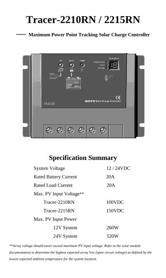
Specification Summary
System Voltage 12 / 24VDC
Rated Battery Current 20A
Rated Load Current 20A
Max. PV Input Voltage**
Tracer-2210RN 100VDC
Tracer-2215RN 150VDC
Max. PV Input Power
12V System 260W
24V System 520W
**Array voltage should never exceed maximum PV input voltage. Refer to the solar module
documentation to determine the highest expected array Voc (open circuit voltage) as defined by the
lowest expected ambient temperature for the system location.
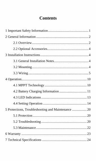
Contents
1 Important Safety Information ............................................... 1
2 General Information ............................................................. 2
2.1 Overview .................................................................. 2
2.2 Optional Accessories................................................ 4
3 Installation Instructions ........................................................ 4
3.1 General Installation Notes ........................................ 4
3.2 Mounting .................................................................. 4
3.3 Wiring ...................................................................... 5
4 Operation ............................................................................ 10
4.1 MPPT Technology ................................................. 10
4.2 Battery Charging Information ................................ 11
4.3 LED Indications ..................................................... 13
4.4 Setting Operation ................................................... 14
5 Protections, Troubleshooting and Maintenance ................. 20
5.1 Protection ............................................................... 20
5.2 Troubleshooting ..................................................... 20
5.3 Maintenance ........................................................... 22
6 Warranty ............................................................................ 23
7 Technical Specifications .................................................... 24
1
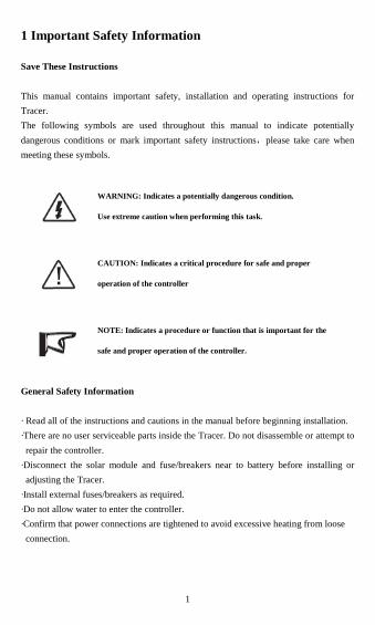
1 Important Safety Information
Save These Instructions
This manual contains important safety, installation and operating instructions for
Tracer.
The following symbols are used throughout this manual to indicate potentially
dangerous conditions or mark important safety instructions,please take care when
meeting these symbols.
WARNING: Indicates a potentially dangerous condition.
Use extreme caution when performing this task.
CAUTION: Indicates a critical procedure for safe and proper
operation of the controller
NOTE: Indicates a procedure or function that is important for the
safe and proper operation of the controller.
General Safety Information
· Read all of the instructions and cautions in the manual before beginning installation.
·There are no user serviceable parts inside the Tracer. Do not disassemble or attempt to
repair the controller.
·Disconnect the solar module and fuse/breakers near to battery before installing or
adjusting the Tracer.
·Install external fuses/breakers as required.
·Do not allow water to enter the controller.
·Confirm that power connections are tightened to avoid excessive heating from loose
connection.
2
2 General Information
2.1 Overview
Thank you for selecting the Tracer controller which represents advanced technology of
our company. The features are listed below:
·12V / 24V auto recognition.
·Advanced maximum power point tracking technology to optimize using the solar
system.
·Peak conversion efficiency of 97 %, high Tracking efficiency of 99%.
·Very fast sweeping of the entire I-V curve, several seconds tracking speed.
·Widely used, automatic recognize day/night.
·Timer function with 1-15 hours option for street light.
·Unique dual timer function, enhance the flexibility of street light system.
·Sealed, Gel and Flooded battery option.
·Adopting temperature compensation and correcting the charging and discharging
parameters automatically, improving the battery lifetime.
·Electronic protection: over charging, over discharging, overload, short circuit.
·Reverse protection: any combination of solar module and battery, without causing
damage to any component.
·Excellent thermal design and nature air cooling.
·RJ45 interface with remote meter MT-5, convenient to check operating parameters of
controllers.
The Tracer series controller is for off-grid solar system and control the charging
and discharging of the battery, especially suitable for the street light system. The
controller features a smart tracking algorithm inside that maximizes the energy from
the solar PV module(s) and charge the battery. At the same time, the low voltage
disconnect function (LVD) will prevent the battery from over discharging.
The Tracer controller charging process has been optimized for long battery life
and improved system performance. The comprehensive self-diagnostics and electronic
protection functions can prevent damage from installation mistakes or system faults. In
addition, the Tracer controller has a RJ45 interface to allow communication with a
meter for remote monitoring.
Although the Tracer controller is very simple to configure and use, please take
your time to read the operator's manual and become familiar with the controller. This
will help you make full use of all the functions and improve your solar PV system.
3
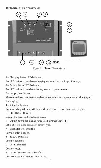
The features of Tracer controller:
1 – Charging Status LED Indicator
An LED indicator that shows charging status and overvoltage of battery.
2 – Battery Status LED Indicator
An LED indicator that shows battery status or system errors.
3 – Temperature Sensor
Measure ambient temperature and make temperature compensation for charging and
discharging.
4 – Setting Indicators
Corresponding indicator will be on when set timer1, timer2 and battery type.
5 – LED Digital Display
Display the load work mode and status.
6 – Setting Button (in manual mode used for load ON/OFF)
Set load work mode and select battery type.
7 – Solar Module Terminals
Connect solar modules.
8 – Battery Terminals
Connect batteries.
9 – Load Terminals
Connect loads.
10 – RJ45 Communication Interface
Communicate with remote meter MT-5.
Figure 2-1 Tracer Characteristics
4 1
1 1
3 1 1
2
5 1
6 1
5 6 7 5 6 7
1
10 9 8 7 1 1 1 1
4
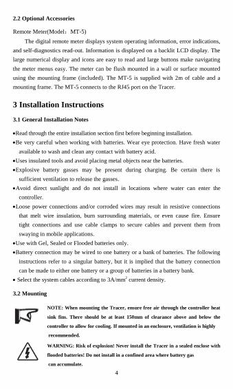
2.2 Optional Accessories
Remote Meter(Model:MT-5)
The digital remote meter displays system operating information, error indications,
and self-diagnostics read-out. Information is displayed on a backlit LCD display. The
large numerical display and icons are easy to read and large buttons make navigating
the meter menus easy. The meter can be flush mounted in a wall or surface mounted
using the mounting frame (included). The MT-5 is supplied with 2m of cable and a
mounting frame. The MT-5 connects to the RJ45 port on the Tracer.
3 Installation Instructions
3.1 General Installation Notes
Read through the entire installation section first before beginning installation.
Be very careful when working with batteries. Wear eye protection. Have fresh water
available to wash and clean any contact with battery acid.
Uses insulated tools and avoid placing metal objects near the batteries.
Explosive battery gasses may be present during charging. Be certain there is
sufficient ventilation to release the gasses.
Avoid direct sunlight and do not install in locations where water can enter the
controller.
Loose power connections and/or corroded wires may result in resistive connections
that melt wire insulation, burn surrounding materials, or even cause fire. Ensure
tight connections and use cable clamps to secure cables and prevent them from
swaying in mobile applications.
Use with Gel, Sealed or Flooded batteries only.
Battery connection may be wired to one battery or a bank of batteries. The following
instructions refer to a singular battery, but it is implied that the battery connection
can be made to either one battery or a group of batteries in a battery bank.
Select the system cables according to 3A/mm2 current density.
3.2 Mounting
NOTE: When mounting the Tracer, ensure free air through the controller heat
sink fins. There should be at least 150mm of clearance above and below the
controller to allow for cooling. If mounted in an enclosure, ventilation is highly
recommended.
WARNING: Risk of explosion! Never install the Tracer in a sealed enclose with
flooded batteries! Do not install in a confined area where battery gas
can accumulate.
5
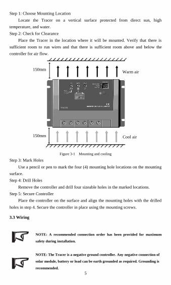
Step 1: Choose Mounting Location
Locate the Tracer on a vertical surface protected from direct sun, high
temperature, and water.
Step 2: Check for Clearance
Place the Tracer in the location where it will be mounted. Verify that there is
sufficient room to run wires and that there is sufficient room above and below the
controller for air flow.
Figure 3-1 Mounting and cooling
Step 3: Mark Holes
Use a pencil or pen to mark the four (4) mounting hole locations on the mounting
surface.
Step 4: Drill Holes
Remove the controller and drill four sizeable holes in the marked locations.
Step 5: Secure Controller
Place the controller on the surface and align the mounting holes with the drilled
holes in step 4. Secure the controller in place using the mounting screws.
3.3 Wiring
NOTE: A recommended connection order has been provided for maximum
safety during installation.
NOTE: The Tracer is a negative ground controller. Any negative connection of
solar module, battery or load can be earth grounded as required. Grounding is
recommended.
150mm
150mm
Warm air
Cool air
6
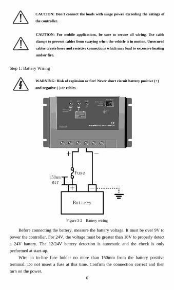
CAUTION: Don’t connect the loads with surge power exceeding the ratings of
the controller.
CAUTION: For mobile applications, be sure to secure all wiring. Use cable
clamps to prevent cables from swaying when the vehicle is in motion. Unsecured
cables create loose and resistive connections which may lead to excessive heating
and/or fire.
Step 1: Battery Wiring
WARNING: Risk of explosion or fire! Never short circuit battery positive (+)
and negative (-) or cables
Figure 3-2 Battery wiring
Before connecting the battery, measure the battery voltage. It must be over 9V to
power the controller. For 24V, the voltage must be greater than 18V to properly detect
a 24V battery. The 12/24V battery detection is automatic and the check is only
performed at start-up.
Wire an in-line fuse holder no more than 150mm from the battery positive
terminal. Do not insert a fuse at this time. Confirm the connection correct and then
turn on the power.
7
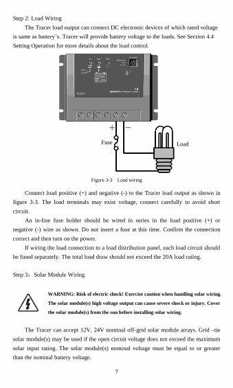
Step 2: Load Wiring
The Tracer load output can connect DC electronic devices of which rated voltage
is same as battery’s. Tracer will provide battery voltage to the loads. See Section 4.4
Setting Operation for more details about the load control.
Figure 3-3 Load wiring
Connect load positive (+) and negative (-) to the Tracer load output as shown in
figure 3-3. The load terminals may exist voltage, connect carefully to avoid short
circuit.
An in-line fuse holder should be wired in series in the load positive (+) or
negative (-) wire as shown. Do not insert a fuse at this time. Confirm the connection
correct and then turn on the power.
If wiring the load connection to a load distribution panel, each load circuit should
be fused separately. The total load draw should not exceed the 20A load rating.
Step 3:Solar Module Wiring
WARNING: Risk of electric shock! Exercise caution when handling solar wiring.
The solar module(s) high voltage output can cause severe shock or injury. Cover
the solar module(s) from the sun before installing solar wiring.
The Tracer can accept 12V, 24V nominal off-grid solar module arrays. Grid –tie
solar module(s) may be used if the open circuit voltage does not exceed the maximum
solar input rating. The solar module(s) nominal voltage must be equal to or greater
than the nominal battery voltage.
Fuse Load
8
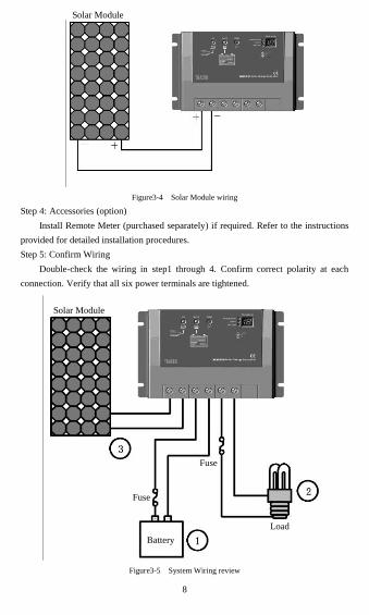
Figure3-4 Solar Module wiring
Step 4: Accessories (option)
Install Remote Meter (purchased separately) if required. Refer to the instructions
provided for detailed installation procedures.
Step 5: Confirm Wiring
Double-check the wiring in step1 through 4. Confirm correct polarity at each
connection. Verify that all six power terminals are tightened.
Figure3-5 System Wiring review
Solar Module
Solar Module
Fuse
Fuse
Load
Battery

9
Step 6: Confirm Power-up
When battery power is applied and the Tracer powers up, the battery led indicator
will be green.
If the Tracer does not power up or battery status LEDs error exists, refer to
Section 5 Troubleshooting
10
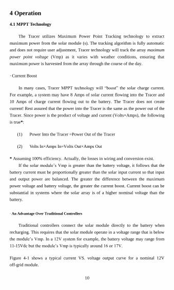
4 Operation
4.1 MPPT Technology
The Tracer utilizes Maximum Power Point Tracking technology to extract
maximum power from the solar module (s). The tracking algorithm is fully automatic
and does not require user adjustment, Tracer technology will track the array maximum
power point voltage (Vmp) as it varies with weather conditions, ensuring that
maximum power is harvested from the array through the course of the day.
· Current Boost
In many cases, Tracer MPPT technology will ―boost‖ the solar charge current.
For example, a system may have 8 Amps of solar current flowing into the Tracer and
10 Amps of charge current flowing out to the battery. The Tracer does not create
current! Rest assured that the power into the Tracer is the same as the power out of the
Tracer. Since power is the product of voltage and current (Volts×Amps), the following
is true*:
(1) Power Into the Tracer =Power Out of the Tracer
(2) Volts In×Amps In=Volts Out×Amps Out
* Assuming 100% efficiency. Actually, the losses in wiring and conversion exist.
If the solar module’s Vmp is greater than the battery voltage, it follows that the
battery current must be proportionally greater than the solar input current so that input
and output power are balanced. The greater the difference between the maximum
power voltage and battery voltage, the greater the current boost. Current boost can be
substantial in systems where the solar array is of a higher nominal voltage than the
battery.
· An Advantage Over Traditional Controllers
Traditional controllers connect the solar module directly to the battery when
recharging. This requires that the solar module operate in a voltage range that is below
the module’s Vmp. In a 12V system for example, the battery voltage may range from
11-15Vdc but the module’s Vmp is typically around 16 or 17V.
Figure 4-1 shows a typical current VS. voltage output curve for a nominal 12V
off-grid module.
11
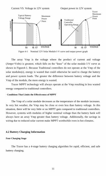
Current VS. Voltage in 12V system Output power in 12V system
Figure 4-1 Nominal 12V Solar Module I-V curve and output power graph
The array Vmp is the voltage where the product of current and voltage
(Amps×Volts) is greatest, which falls on the ―knee‖ of the solar module I-V curve as
shown in Figure4-1. Because Traditional controllers do not operate at the Vmp of the
solar modules(s), energy is wasted that could otherwise be used to charge the battery
and power system loads. The greater the difference between battery voltage and the
Vmp of the module, the more energy is wasted.
Tracer MPPT technology will always operate at the Vmp resulting in less wasted
energy compared to traditional controllers.
· Conditions That Limits the Effectiveness of MPPT
The Vmp of a solar module decreases as the temperature of the module increases.
In very hot weather, the Vmp may be close or even less than battery voltage. In this
situation, there will be very little or no MPPT gain compared to traditional controllers.
However, systems with modules of higher nominal voltage than the battery bank will
always have an array Vmp greater than battery voltage. Additionally, the savings in
wiring due to reduced solar current make MPPT worthwhile even in hot climates.
4.2 Battery Charging Information
Four Charging Stage
The Tracer has a 4-stage battery charging algorithm for rapid, efficient, and safe
battery charging.
Typical Battery Voltage Range
Point
Power
Traditional
Maximum
Operating Range Controller
Tracer
Point Power Maximum
12
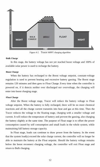
Figure 4-2 Tracer MPPT charging algorithm
·Bulk Charge
In this stage, the battery voltage has not yet reached boost voltage and 100% of
available solar power is used to recharge the battery.
·Boost Charge
When the battery has recharged to the Boost voltage setpoint, constant-voltage
regulation is used to prevent heating and excessive battery gassing. The Boost stage
remains 120 minutes and then goes to Float Charge. Every time when the controller is
powered on, if it detects neither over discharged nor overvoltage, the charging will
enter into boost charging stage.
·Float Charge
After the Boost voltage stage, Tracer will reduce the battery voltage to Float
voltage setpoint. When the battery is fully recharged, there will be no more chemical
reactions and all the charge current transmits into heat and gas at this time. Then the
Tracer reduces the voltage to the floating stage, charging with a smaller voltage and
current. It will reduce the temperature of battery and prevent the gassing, also charging
the battery slightly at the same time. The purpose of Float stage is to offset the power
consumption caused by self consumption and small loads in the whole system, while
maintaining full battery storage capacity.
In Float stage, loads can continue to draw power from the battery. In the event
that the system load(s) exceed the solar charge current, the controller will no longer be
able to maintain the battery at the Float setpoint. Should the battery voltage remains
below the boost reconnect charging voltage, the controller will exit Float stage and
return to Bulk charging.
13
·Equalize
WARNING: Risk of explosion!
Equalizing flooded battery can produce explosive gases, so well ventilation
of battery box is necessary.
NOTE: Equipment damage!
Equalization may increase battery voltage to the level damaging to sensitive
DC loads. Ensure that all load allowable input voltages are greater than the
equalizing charging set point voltage.
NOTE: Equipment damage!
Over-charging and excessive gas precipitation may damage the battery plates
and activate material shedding on them. Too high an equalizing charge or for
too long may cause damage. Please carefully review the specific requirements
of the battery used in the system.
Certain types of batteries benefit from periodic equalizing charge, which can stir
the electrolyte, balance battery voltage and complete chemical reaction. Equalizing
charge increases the battery voltage, higher than the standard complement voltage,
which gasifies the battery electrolyte.
If it detects that the battery is being over discharged, the solar controller will
automatically turn the battery to equalization charging stage, and the equalization
charging will be 120mins. Equalizing charge and boost charge are not carried out
constantly in a full charge process to avoid too much gas precipitation or overheating
of battery.
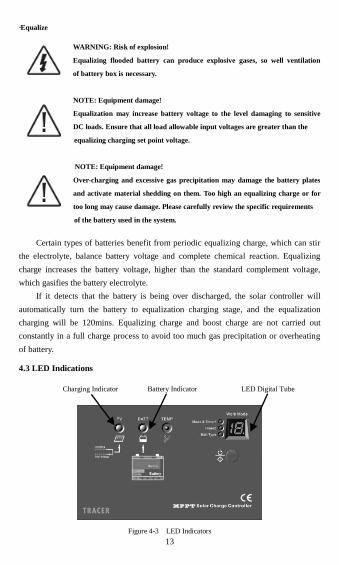
4.3 LED Indications
Charging Indicator Battery Indicator LED Digital Tube
Figure 4-3 LED Indicators
14
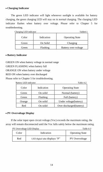
Charging Indicator
The green LED indicator will light whenever sunlight is available for battery
charging, the green charging LED will stay on in normal charging. The charging LED
indicator flashes when battery over voltage. Please refer to Chapter 5 for
troubleshooting.
Charging LED indicator Table4-1
Color Indication Operating State
Green On Solid Charging
Green Flashing Battery over-voltage
Battery Indicator
GREEN ON when battery voltage in normal range
GREEN FLASHING when battery full
ORANGE ON when battery under voltage
RED ON when battery over discharged
Please refer to Chapter 5 for troubleshooting.
Battery LED indicator Table 4-2
Color Indication Operating State
Green On solid Normal (battery)
Green Flashing Full (battery)
Orange On solid Under voltage(battery)
Red On solid Over discharged(battery)
PV Overvoltage Display
If the solar input open circuit voltage (Voc) exceeds the maximum rating, the
array will remain disconnected until the Voc falls safely below the maximum rating.
PV Overvoltage LED Display Table 4-3
Color Indication Operating State
Red LED digital tube displays ―P‖ PV Overvoltage
15
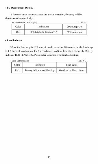
PV Overcurrent Display
If the solar input current exceeds the maximum rating, the array will be
disconnected automatically.
PV Overcurrent LED Display Table 4-4
Color Indication Operating State
Red LED digital tube displays ―C‖ PV Overcurrent
Load indicator
When the load amp is 1.25times of rated current for 60 seconds, or the load amp
is 1.5 times of rated current for 5 seconds (overload); or load short circuit, the Battery
Indicator RED FLASHING. Please refer to section 5 for troubleshooting.
Load LED indicator Table 4-5
Color Indication Load status
Red battery indicator red flashing Overload or Short circuit
16
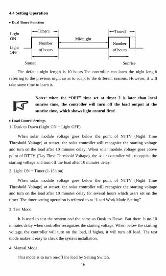
4.4 Setting Operation
Dual Timer Function
The default night length is 10 hours.The controller can learn the night length
referring to the previous night so as to adapt to the different seasons. However, it will
take some time to learn it.
Notes: when the “OFF” time set at timer 2 is later than local
sunrise time, the controller will turn off the load output at the
sunrise time, which shows light control first!
Load Control Settings
1. Dusk to Dawn (Light ON + Light OFF)
When solar module voltage goes below the point of NTTV (Night Time
Threshold Voltage) at sunset, the solar controller will recognize the starting voltage
and turn on the load after 10 minutes delay; When solar module voltage goes above
point of DTTV (Day Time Threshold Voltage), the solar controller will recognize the
starting voltage and turn off the load after 10 minutes delay.
2. Light ON + Timer (1-15h on)
When solar module voltage goes below the point of NTTV (Night Time
Threshold Voltage) at sunset; the solar controller will recognize the starting voltage
and turn on the load after 10 minutes delay for several hours which users set on the
timer. The timer setting operation is referred to as ―Load Work Mode Setting‖.
3. Test Mode
It is used to test the system and the same as Dusk to Dawn. But there is no 10
minutes delay when controller recognizes the starting voltage. When below the starting
voltage, the controller will turn on the load, if higher, it will turn off load. The test
mode makes it easy to check the system installation.
4. Manual Mode
This mode is to turn on/off the load by Setting Switch.
Light
ON
Light
OFF
Timer1
Number
of hours
Sunset
Midnight
Timer2
Number
of hours
Sunrise
17
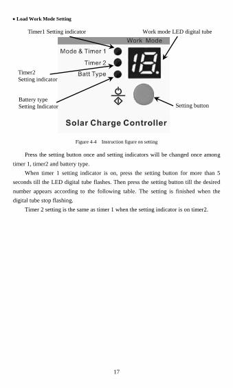
Load Work Mode Setting
Timer1 Setting indicator Work mode LED digital tube
Figure 4-4 Instruction figure on setting
Press the setting button once and setting indicators will be changed once among
timer 1, timer2 and battery type.
When timer 1 setting indicator is on, press the setting button for more than 5
seconds till the LED digital tube flashes. Then press the setting button till the desired
number appears according to the following table. The setting is finished when the
digital tube stop flashing.
Timer 2 setting is the same as timer 1 when the setting indicator is on timer2.
Timer2
Setting indicator
Battery type
Setting Indicator Setting button
18
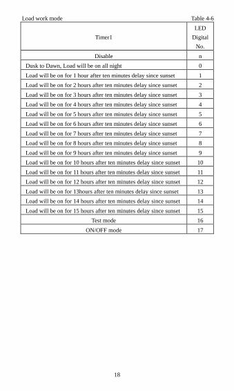
Load work mode Table 4-6
Timer1
LED
Digital
No.
Disable n
Dusk to Dawn, Load will be on all night 0
Load will be on for 1 hour after ten minutes delay since sunset 1
Load will be on for 2 hours after ten minutes delay since sunset 2
Load will be on for 3 hours after ten minutes delay since sunset 3
Load will be on for 4 hours after ten minutes delay since sunset 4
Load will be on for 5 hours after ten minutes delay since sunset 5
Load will be on for 6 hours after ten minutes delay since sunset 6
Load will be on for 7 hours after ten minutes delay since sunset 7
Load will be on for 8 hours after ten minutes delay since sunset 8
Load will be on for 9 hours after ten minutes delay since sunset 9
Load will be on for 10 hours after ten minutes delay since sunset 10
Load will be on for 11 hours after ten minutes delay since sunset 11
Load will be on for 12 hours after ten minutes delay since sunset 12
Load will be on for 13hours after ten minutes delay since sunset 13
Load will be on for 14 hours after ten minutes delay since sunset 14
Load will be on for 15 hours after ten minutes delay since sunset 15
Test mode 16
ON/OFF mode 17
19
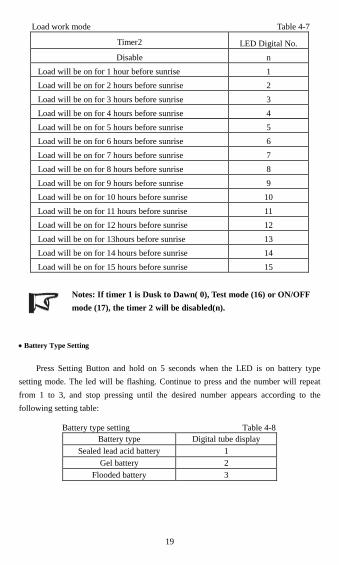
Load work mode Table 4-7
Timer2 LED Digital No.
Disable n
Load will be on for 1 hour before sunrise 1
Load will be on for 2 hours before sunrise 2
Load will be on for 3 hours before sunrise 3
Load will be on for 4 hours before sunrise 4
Load will be on for 5 hours before sunrise 5
Load will be on for 6 hours before sunrise 6
Load will be on for 7 hours before sunrise 7
Load will be on for 8 hours before sunrise 8
Load will be on for 9 hours before sunrise 9
Load will be on for 10 hours before sunrise 10
Load will be on for 11 hours before sunrise 11
Load will be on for 12 hours before sunrise 12
Load will be on for 13hours before sunrise 13
Load will be on for 14 hours before sunrise 14
Load will be on for 15 hours before sunrise 15
Notes: If timer 1 is Dusk to Dawn( 0), Test mode (16) or ON/OFF
mode (17), the timer 2 will be disabled(n).
Battery Type Setting
Press Setting Button and hold on 5 seconds when the LED is on battery type
setting mode. The led will be flashing. Continue to press and the number will repeat
from 1 to 3, and stop pressing until the desired number appears according to the
following setting table:
Battery type setting Table 4-8
Battery type Digital tube display
Sealed lead acid battery 1
Gel battery 2
Flooded battery 3
20
5 Protections, Troubleshooting and Maintenance
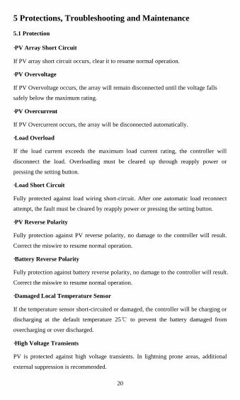
5.1 Protection
·PV Array Short Circuit
If PV array short circuit occurs, clear it to resume normal operation.
·PV Overvoltage
If PV Overvoltage occurs, the array will remain disconnected until the voltage falls
safely below the maximum rating.
·PV Overcurrent
If PV Overcurrent occurs, the array will be disconnected automatically.
·Load Overload
If the load current exceeds the maximum load current rating, the controller will
disconnect the load. Overloading must be cleared up through reapply power or
pressing the setting button.
·Load Short Circuit
Fully protected against load wiring short-circuit. After one automatic load reconnect
attempt, the fault must be cleared by reapply power or pressing the setting button.
·PV Reverse Polarity
Fully protection against PV reverse polarity, no damage to the controller will result.
Correct the miswire to resume normal operation.
·Battery Reverse Polarity
Fully protection against battery reverse polarity, no damage to the controller will result.
Correct the miswire to resume normal operation.
·Damaged Local Temperature Sensor
If the temperature sensor short-circuited or damaged, the controller will be charging or
discharging at the default temperature 25℃ to prevent the battery damaged from
overcharging or over discharged.
·High Voltage Transients
PV is protected against high voltage transients. In lightning prone areas, additional
external suppression is recommended.
21
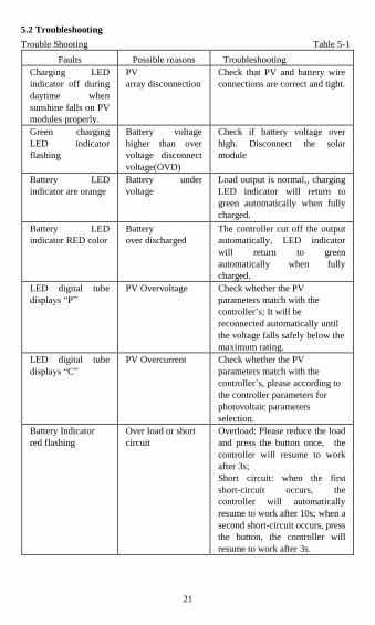
5.2 Troubleshooting
Trouble Shooting Table 5-1
Faults Possible reasons Troubleshooting
Charging LED
indicator off during
daytime when
sunshine falls on PV
modules properly.
PV
array disconnection
Check that PV and battery wire
connections are correct and tight.
Green charging
LED indicator
flashing
Battery voltage
higher than over
voltage disconnect
voltage(OVD)
Check if battery voltage over
high. Disconnect the solar
module
Battery LED
indicator are orange
Battery under
voltage
Load output is normal,, charging
LED indicator will return to
green automatically when fully
charged.
Battery LED
indicator RED color
Battery
over discharged
The controller cut off the output
automatically, LED indicator
will return to green
automatically when fully
charged.
LED digital tube
displays ―P‖
PV Overvoltage Check whether the PV
parameters match with the
controller’s; It will be
reconnected automatically until
the voltage falls safely below the
maximum rating.
LED digital tube
displays ―C‖
PV Overcurrent Check whether the PV
parameters match with the
controller’s, please according to
the controller parameters for
photovoltaic parameters
selection.
Battery Indicator
red flashing
Over load or short
circuit
Overload: Please reduce the load
and press the button once, the
controller will resume to work
after 3s;
Short circuit: when the first
short-circuit occurs, the
controller will automatically
resume to work after 10s; when a
second short-circuit occurs, press
the button, the controller will
resume to work after 3s.
22
5.3 Maintenance
The following inspections and maintenance tasks are recommended at least two
times per year for best controller performance.
Check that the controller is securely mounted in a clean and dry environment.
Check that the air flow and ventilation around the controller is not blocked. Clear all
dirt or fragments on the heat sink.
Check all the naked wires to make sure insulation is not damaged for serious
solarization, frictional wear, dryness, insects or rats etc. Maintain or replace the wires
if necessary.
Tighten all the terminals. Inspect for loose, broken, or burnt wire connections.
Check and confirm that LED digital tube is consistent with required. Pay attention to
any troubleshooting or error indication .Take necessary corrective action.
Confirm that all the system components are ground connected tightly and correctly.
Confirm that all the terminals have no corrosion, insulation damaged, high
temperature or burnt/discolored sign, tighten terminal screws to the suggested torque.
Inspect for dirt, insects and corrosion, and clear up.
Check and confirm that lightning arrester is in good condition. Replace a new one in
time to avoid damaging of the controller and even other equipments.
Warning:Risk of electric shock!
Make sure all the power is turned off before above operations, and then follow
the corresponding inspections and operations.
23
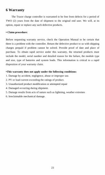
6 Warranty
The Tracer charge controller is warranted to be free from defects for a period of
TWO (2) years from the date of shipment to the original end user. We will, at its
option, repair or replace any such defective products.
• Claim procedure:
Before requesting warranty service, check the Operation Manual to be certain that
there is a problem with the controller. Return the defective product to us with shipping
charges prepaid if problem cannot be solved. Provide proof of date and place of
purchase. To obtain rapid service under this warranty, the returned products must
include the model, serial number and detailed reason for the failure, the module type
and size, type of batteries and system loads. This information is critical to a rapid
disposition of your warranty claim.
•This warranty does not apply under the following conditions:
1. Damage by accident, negligence, abuse or improper use.
2. PV or load current exceeding the ratings of product.
3. Unauthorized product modification or attempted repair
4. Damaged occurring during shipment.
5. Damage results from acts of nature such as lightning, weather extremes
6. Irreclaimable mechanical damage.
24
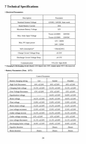
7 Technical Specifications
• Electrical Parameters
Description Parameter
Nominal System Voltage 12VDC / 24VDC Auto work
Rated Battery Current 20A
Maximum Battery Voltage 32V
Max. Solar Input Voltage Tracer-2210RN 100VDC
Tracer-2215RN 150VDC
Max. PV input power 12V / 260W
24V / 520W
Self-consumption* <10mA(24V)
Charge Circuit Voltage Drop ≤0.26V
Discharge Circuit Voltage Drop ≤0.15V
Communication TTL232 / 8pin RJ45
* Charging & discharging circuit closed, LED digital tube OFF, remote meter MT-5 disconnected.
• Battery Parameters (Tem:25℃)
Control Parameter
Battery charging setting Gel Sealed Flooded
High Volt Disconnect 16V; x2/24V 16V; x2/24V 16V; x2/24V
Charging limit voltage 15.5V; x2/24V 15.5V; x2/24V 15.5V; x2/24V
Over Voltage Reconnect 15V; x2/24V 15V; x2/24V 15V; x2/24V
Equalization voltage —— 14.6V; x2/24V 14.8V; x2/24V
Boost voltage 14.2V; x2/24V 14.4V; x2/24V 14.6V; x2/24V
Float voltage 13.8V; x2/24V 13.8V; x2/24V 13.8V; x2/24V
Boost return voltage 13.2V; x2/24V 13.2V; x2/24V 13.2V; x2/24V
Low voltage reconnect 12.6V; x2/24V 12.6V; x2/24V 12.6V; x2/24V
Under voltage recover 12.2V; x2/24V 12.2V; x2/24V 12.2V; x2/24V
Under voltage warning 12V; x2/24V 12V; x2/24V 12V; x2/24V
Low voltage disconnect 11.1V; x2/24V 11.1V; x2/24V 11.1V; x2/24V
Discharging limits voltage 10.8V; x2/24V 10.8V; x2/24V 10.8V; x2/24V
Equalize duration —— 2hours 2hours
Boost duration 2hours 2hours 2hours
25
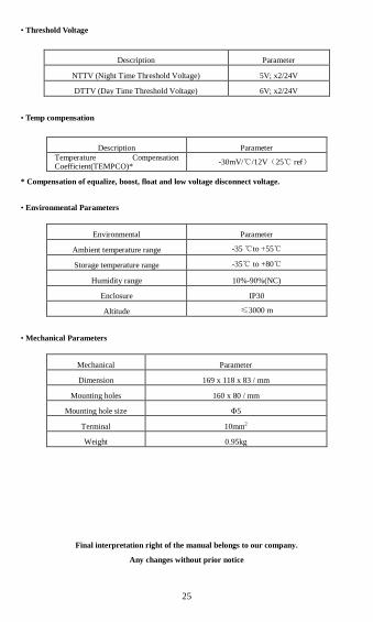
• Threshold Voltage
Description Parameter
NTTV (Night Time Threshold Voltage) 5V; x2/24V
DTTV (Day Time Threshold Voltage) 6V; x2/24V
• Temp compensation
Description Parameter
Temperature Compensation Coefficient(TEMPCO)*
-30mV/℃/12V(25℃ ref)
* Compensation of equalize, boost, float and low voltage disconnect voltage.
• Environmental Parameters
Environmental Parameter
Ambient temperature range -35 ℃to +55℃
Storage temperature range -35℃ to +80℃
Humidity range 10%-90%(NC)
Enclosure IP30
Altitude ≤3000 m
• Mechanical Parameters
Mechanical Parameter
Dimension 169 x 118 x 83 / mm
Mounting holes 160 x 80 / mm
Mounting hole size Φ5
Terminal 10mm2
Weight 0.95kg
Final interpretation right of the manual belongs to our company.
Any changes without prior notice
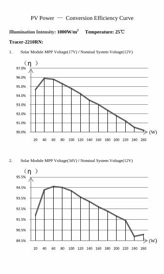
PV Power — Conversion Efficiency Curve
Illumination Intensity: 1000W/m2
Temperature: 25℃
Tracer-2210RN:
1. Solar Module MPP Voltage(17V) / Nominal System Voltage(12V)
2. Solar Module MPP Voltage(34V) / Nominal System Voltage(12V)
90.0%
91.0%
92.0%
93.0%
94.0%
95.0%
96.0%
97.0%
20 40 60 80 100 120 140 160 180 200 220 240 260
89.5%
90.5%
91.5%
92.5%
93.5%
94.5%
95.5%
20 40 60 80 100 120 140 160 180 200 220 240 260
(η )
(η )
(W)
(W)
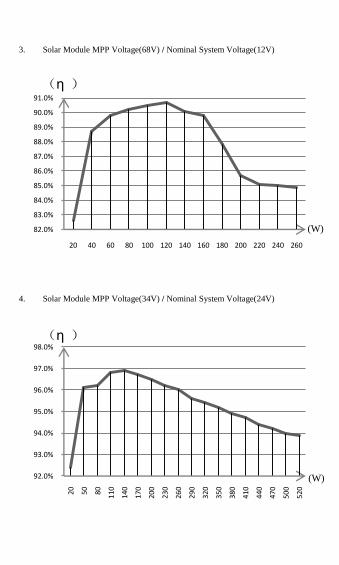
3. Solar Module MPP Voltage(68V) / Nominal System Voltage(12V)
4. Solar Module MPP Voltage(34V) / Nominal System Voltage(24V)
82.0%
83.0%
84.0%
85.0%
86.0%
87.0%
88.0%
89.0%
90.0%
91.0%
20 40 60 80 100 120 140 160 180 200 220 240 260
92.0%
93.0%
94.0%
95.0%
96.0%
97.0%
98.0%
20 50 80 110
140
170
200
230
260
290
320
350
380
410
440
470
500
520
(W)
(η )
(W)
(η )
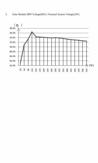
5. Solar Module MPP Voltage(68V) / Nominal System Voltage(24V)
82.0%
84.0%
86.0%
88.0%
90.0%
92.0%
94.0%
96.0%
98.0%
20 50 80 110
140
170
200
230
260
290
320
350
380
410
440
470
500
520
(W)
(η )
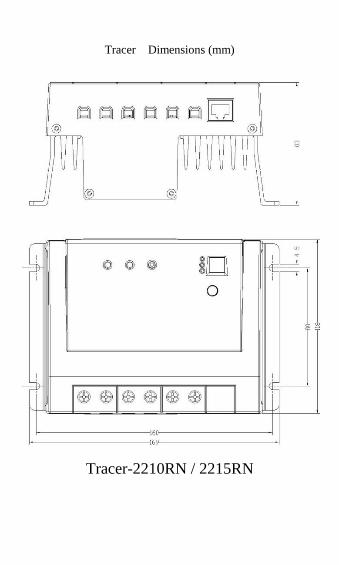
Tracer Dimensions (mm)
Tracer-2210RN / 2215RN

Version number: V6.0


BEIJING EPSOLAR TECHNOLOGY CO., LTD.
Tel:010-82894112 / 82894962
Fax:010-82894882
E-mail:[email protected]
Website:www.epsolarpv.com