Embed Size (px)
Citation preview
The Reliable Automatic Sprinkler Co., Inc., 103 Fairview Park Drive, Elmsford, New York 10523
Bulletin 323 R
ev. EBulletin 323 Rev. E
Instructions forInstallation, Operation, Care and Maintenance
Model B1 Accelerator with IntegralAccelo-Check
Features1. Quickens the operation of dry pipe valves.2. Increases the number of automatic sprin-
klers controlled by one dry pipe valve.3. Equalizes rapidly as dry system is being
fi lled with air to required pressure.4. Adjusts without operation for small fl uc-
tuations in system air pressure.5. Dependable in operation, compact and
light-weight construction.6. Accelo-Check prevents water and debris
from entering critical areas, minimizing the need of removing cover plates, etc. to reset or clean internal mechanisms.
7. Tested and approved for use with all Reli-able dry pipe valves and dry systems.
8. UL Listed, FM Approved
GeneralThe Reliable Model B1 Accelerator with its integral Ac-
celo-Check (anti-flooding device) is used to speed up the operation of both dry pipe valves (in dry-type automatic sprinkler systems) and deluge valves (in pre-action sprin-kler systems). Both of these system types utilize pressur-ized air, instead of water, in their piping as to avoid expo-sure to water sensitive areas and/or freezing conditions.
The accelerated operation of the dry pipe valve floods the sprinkler system with water permitting a substantial in-crease in both the number of sprinklers that can be con-trolled by one dry pipe valve and the volume of the dry system that can be installed.
Approvals1. Listed by Underwriters Laboratories, Inc.2. Underwriters’ laboratories of Canada for up to 1500
gal. (5678 liters) systems.3. Approved by Factory Mutual Research Corporation4. Loss Prevention Council5. NYC B5&A No. 587-75-SA.
Patent number 3,785,440
2.
Accelerator OperationThe Model B1 Accelerator is basically a normally-closed
valve with ½” NPT ports, that is highly sensitive to the rate of air pressure change in a dry pipe sprinkler system. This de-vice retains normal dry system air pressure in its top cham-ber even though pressure in that system may be dropping as a direct result from one or more sprinklers opening.
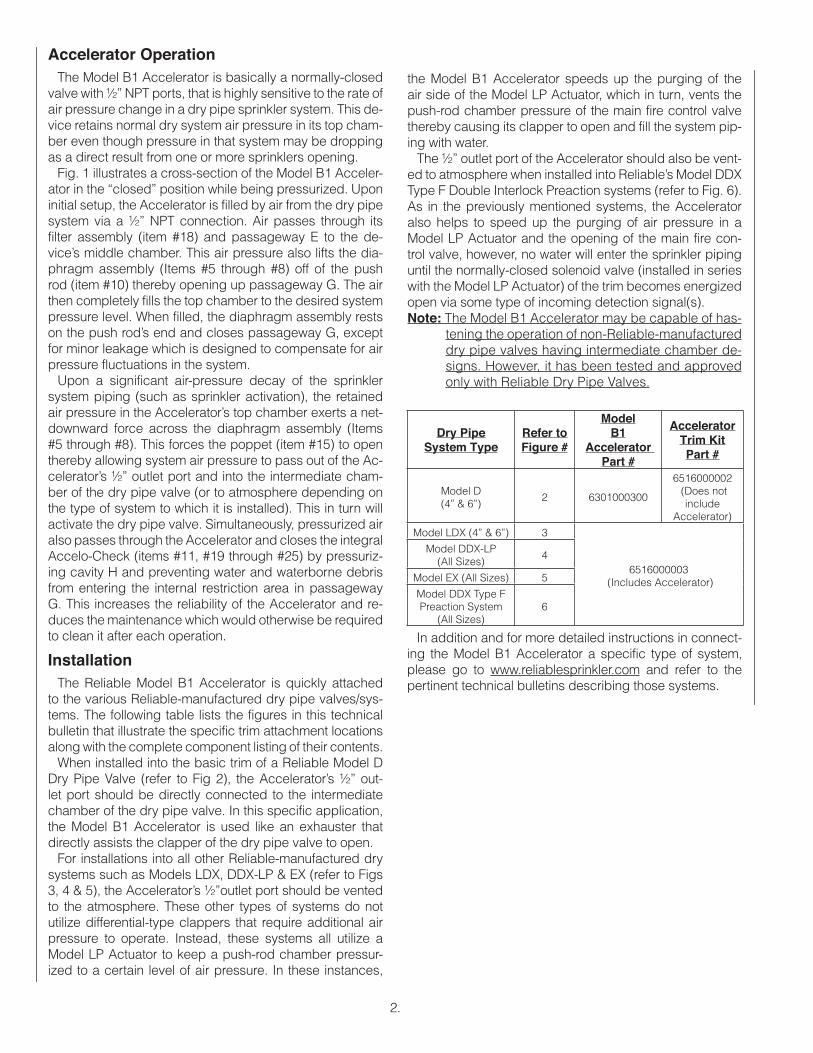
Fig. 1 illustrates a cross-section of the Model B1 Acceler-ator in the “closed” position while being pressurized. Upon initial setup, the Accelerator is filled by air from the dry pipe system via a ½” NPT connection. Air passes through its filter assembly (item #18) and passageway E to the de-vice’s middle chamber. This air pressure also lifts the dia-phragm assembly (Items #5 through #8) off of the push rod (item #10) thereby opening up passageway G. The air then completely fills the top chamber to the desired system pressure level. When filled, the diaphragm assembly rests on the push rod’s end and closes passageway G, except for minor leakage which is designed to compensate for air pressure fluctuations in the system.
Upon a significant air-pressure decay of the sprinkler system piping (such as sprinkler activation), the retained air pressure in the Accelerator’s top chamber exerts a net-downward force across the diaphragm assembly (Items #5 through #8). This forces the poppet (item #15) to open thereby allowing system air pressure to pass out of the Ac-celerator’s ½” outlet port and into the intermediate cham-ber of the dry pipe valve (or to atmosphere depending on the type of system to which it is installed). This in turn will activate the dry pipe valve. Simultaneously, pressurized air also passes through the Accelerator and closes the integral Accelo-Check (items #11, #19 through #25) by pressuriz-ing cavity H and preventing water and waterborne debris from entering the internal restriction area in passageway G. This increases the reliability of the Accelerator and re-duces the maintenance which would otherwise be required to clean it after each operation.
InstallationThe Reliable Model B1 Accelerator is quickly attached
to the various Reliable-manufactured dry pipe valves/sys-tems. The following table lists the figures in this technical bulletin that illustrate the specific trim attachment locations along with the complete component listing of their contents.
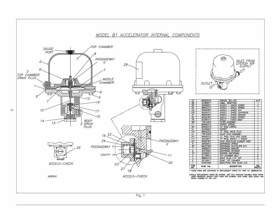
When installed into the basic trim of a Reliable Model D Dry Pipe Valve (refer to Fig 2), the Accelerator’s ½” out-let port should be directly connected to the intermediate chamber of the dry pipe valve. In this specific application, the Model B1 Accelerator is used like an exhauster that directly assists the clapper of the dry pipe valve to open.
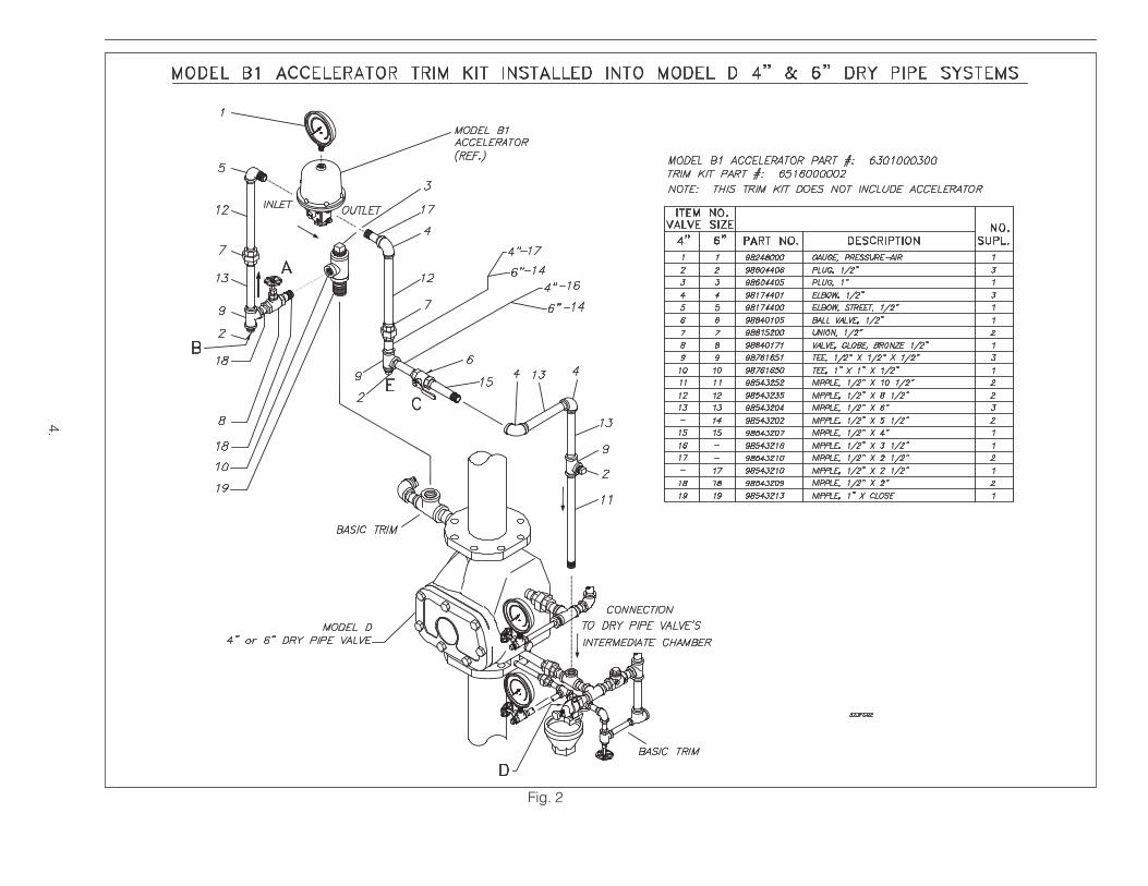
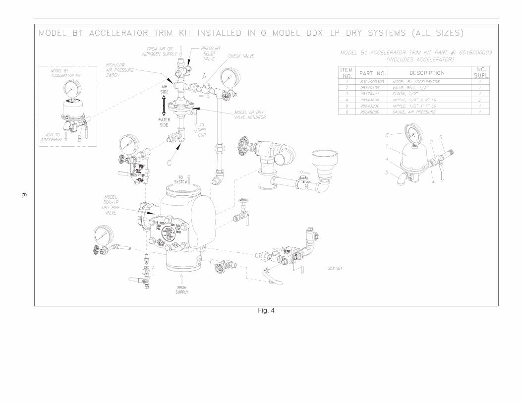
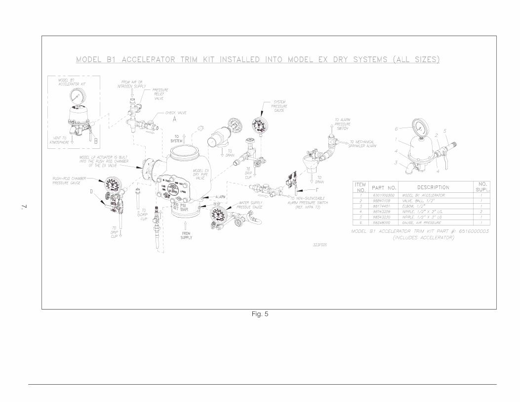
For installations into all other Reliable-manufactured dry systems such as Models LDX, DDX-LP & EX (refer to Figs 3, 4 & 5), the Accelerator’s ½”outlet port should be vented to the atmosphere. These other types of systems do not utilize differential-type clappers that require additional air pressure to operate. Instead, these systems all utilize a Model LP Actuator to keep a push-rod chamber pressur-ized to a certain level of air pressure. In these instances,
Dry PipeSystem Type
Refer toFigure #
ModelB1
Accelerator Part #
AcceleratorTrim KitPart #
Model D(4” & 6”)
2 6301000300
6516000002 (Does not
includeAccelerator)
Model LDX (4” & 6”) 3
6516000003 (Includes Accelerator)
Model DDX-LP(All Sizes)
4
Model EX (All Sizes) 5
Model DDX Type FPreaction System
(All Sizes)6
In addition and for more detailed instructions in connect-ing the Model B1 Accelerator a specific type of system, please go to www.reliablesprinkler.com and refer to the pertinent technical bulletins describing those systems.
the Model B1 Accelerator speeds up the purging of the air side of the Model LP Actuator, which in turn, vents the push-rod chamber pressure of the main fire control valve thereby causing its clapper to open and fill the system pip-ing with water.
The ½” outlet port of the Accelerator should also be vent-ed to atmosphere when installed into Reliable’s Model DDX Type F Double Interlock Preaction systems (refer to Fig. 6). As in the previously mentioned systems, the Accelerator also helps to speed up the purging of air pressure in a Model LP Actuator and the opening of the main fire con-trol valve, however, no water will enter the sprinkler piping until the normally-closed solenoid valve (installed in series with the Model LP Actuator) of the trim becomes energized open via some type of incoming detection signal(s).Note: The Model B1 Accelerator may be capable of has-
tening the operation of non-Reliable-manufactured dry pipe valves having intermediate chamber de-signs. However, it has been tested and approved only with Reliable Dry Pipe Valves.
3.
Fig. 1
4.
Fig. 2
5.
Fig. 3
6.
Fig. 4
7.
Fig. 5
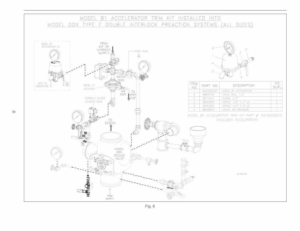
Fig. 6
8.
9.
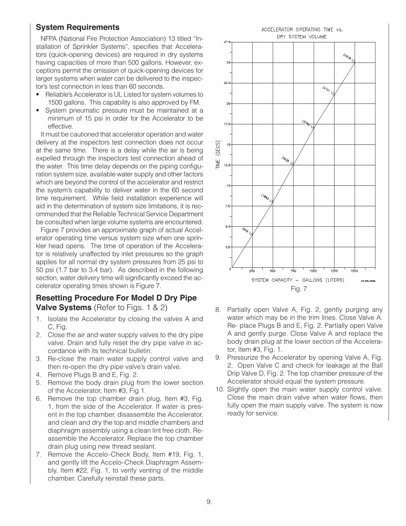
System RequirementsNFPA (National Fire Protection Association) 13 titled “In-
stallation of Sprinkler Systems”, specifies that Accelera-tors (quick-opening devices) are required in dry systems having capacities of more than 500 gallons. However, ex-ceptions permit the omission of quick-opening devices for larger systems when water can be delivered to the inspec-tor’s test connection in less than 60 seconds.• Reliable’s Accelerator is UL Listed for system volumes to
1500 gallons. This capability is also approved by FM.• System pneumatic pressure must be maintained at a
minimum of 15 psi in order for the Accelerator to be effective.
It must be cautioned that accelerator operation and water delivery at the inspectors test connection does not occur at the same time. There is a delay while the air is being expelled through the inspectors test connection ahead of the water. This time delay depends on the piping configu-ration system size, available water supply and other factors which are beyond the control of the accelerator and restrict the system’s capability to deliver water in the 60 second time requirement. While field installation experience will aid in the determination of system size limitations, it is rec-ommended that the Reliable Technical Service Department be consulted when large volume systems are encountered.
Figure 7 provides an approximate graph of actual Accel-erator operating time versus system size when one sprin-kler head opens. The time of operation of the Accelera-tor is relatively unaffected by inlet pressures so the graph applies for all normal dry system pressures from 25 psi to 50 psi (1.7 bar to 3.4 bar). As described in the following section, water delivery time will significantly exceed the ac-celerator operating times shown is Figure 7.
Resetting Procedure For Model D Dry Pipe Valve Systems (Refer to Figs. 1 & 2)1. Isolate the Accelerator by closing the valves A and
C, Fig. 2. Close the air and water supply valves to the dry pipe
valve. Drain and fully reset the dry pipe valve in ac-cordance with its technical bulletin.
3. Re-close the main water supply control valve and then re-open the dry pipe valve’s drain valve.
4. Remove Plugs B and E, Fig. 2.5. Remove the body drain plug from the lower section
of the Accelerator, Item #3, Fig 1.6. Remove the top chamber drain plug, Item #3, Fig.
1, from the side of the Accelerator. If water is pres-ent in the top chamber, disassemble the Accelerator, and clean and dry the top and middle chambers and diaphragm assembly using a clean lint free cloth. Re-assemble the Accelerator. Replace the top chamber drain plug using new thread sealant.
7. Remove the Accelo–Check Body, Item #19, Fig. 1, and gently lift the Accelo–Check Diaphragm Assem-bly, Item #22, Fig. 1, to verify venting of the middle chamber. Carefully reinstall these parts.
8. Partially open Valve A, Fig. 2, gently purging any water which may be in the trim lines. Close Valve A. Re- place Plugs B and E, Fig. 2. Partially open Valve A and gently purge. Close Valve A and replace the body drain plug at the lower section of the Accelera-tor, Item #3, Fig. 1.
9. Pressurize the Accelerator by opening Valve A, Fig. 2. Open Valve C and check for leakage at the Ball Drip Valve D, Fig. 2. The top chamber pressure of the Accelerator should equal the system pressure.
10. Slightly open the main water supply control valve. Close the main drain valve when water flows, then fully open the main supply valve. The system is now ready for service.
Fig. 7
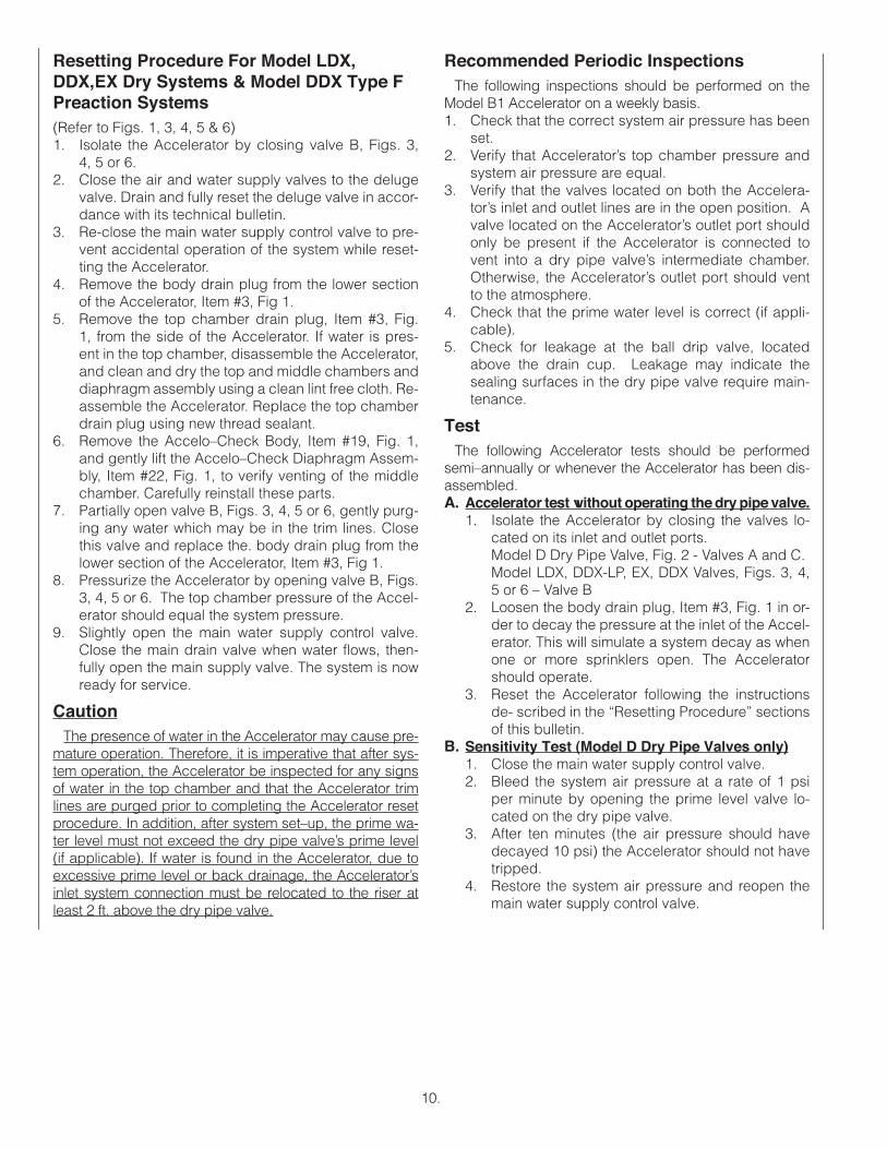
Resetting Procedure For Model LDX, DDX,EX Dry Systems & Model DDX Type F Preaction Systems(Refer to Figs. 1, 3, 4, 5 & 6)1. Isolate the Accelerator by closing valve B, Figs. 3,
4, 5 or 6.2. Close the air and water supply valves to the deluge
valve. Drain and fully reset the deluge valve in accor-dance with its technical bulletin.
3. Re-close the main water supply control valve to pre-vent accidental operation of the system while reset-ting the Accelerator.
4. Remove the body drain plug from the lower section of the Accelerator, Item #3, Fig 1.
5. Remove the top chamber drain plug, Item #3, Fig. 1, from the side of the Accelerator. If water is pres-ent in the top chamber, disassemble the Accelerator, and clean and dry the top and middle chambers and diaphragm assembly using a clean lint free cloth. Re-assemble the Accelerator. Replace the top chamber drain plug using new thread sealant.
6. Remove the Accelo–Check Body, Item #19, Fig. 1, and gently lift the Accelo–Check Diaphragm Assem-bly, Item #22, Fig. 1, to verify venting of the middle chamber. Carefully reinstall these parts.
7. Partially open valve B, Figs. 3, 4, 5 or 6, gently purg-ing any water which may be in the trim lines. Close this valve and replace the. body drain plug from the lower section of the Accelerator, Item #3, Fig 1.
8. Pressurize the Accelerator by opening valve B, Figs. 3, 4, 5 or 6. The top chamber pressure of the Accel-erator should equal the system pressure.
9. Slightly open the main water supply control valve. Close the main drain valve when water flows, then-fully open the main supply valve. The system is now ready for service.
CautionThe presence of water in the Accelerator may cause pre-
mature operation. Therefore, it is imperative that after sys- tem operation, the Accelerator be inspected for any signs of water in the top chamber and that the Accelerator trim lines are purged prior to completing the Accelerator reset procedure. In addition, after system set–up, the prime wa-ter level must not exceed the dry pipe valve’s prime level (if applicable). If water is found in the Accelerator, due to excessive prime level or back drainage, the Accelerator’s inlet system connection must be relocated to the riser at least 2 ft. above the dry pipe valve.
10.
Recommended Periodic InspectionsThe following inspections should be performed on the
Model B1 Accelerator on a weekly basis.1. Check that the correct system air pressure has been
set.2. Verify that Accelerator’s top chamber pressure and
system air pressure are equal.3. Verify that the valves located on both the Accelera-
tor’s inlet and outlet lines are in the open position. A valve located on the Accelerator’s outlet port should only be present if the Accelerator is connected to vent into a dry pipe valve’s intermediate chamber. Otherwise, the Accelerator’s outlet port should vent to the atmosphere.
4. Check that the prime water level is correct (if appli-cable).
5. Check for leakage at the ball drip valve, located above the drain cup. Leakage may indicate the sealing surfaces in the dry pipe valve require main-tenance.
Test The following Accelerator tests should be performed
semi–annually or whenever the Accelerator has been dis-assembled.A. Accelerator test without operating the dry pipe valve.
1. Isolate the Accelerator by closing the valves lo-cated on its inlet and outlet ports. Model D Dry Pipe Valve, Fig. 2 - Valves A and C.Model LDX, DDX-LP, EX, DDX Valves, Figs. 3, 4, 5 or 6 – Valve B
2. Loosen the body drain plug, Item #3, Fig. 1 in or-der to decay the pressure at the inlet of the Accel-erator. This will simulate a system decay as when one or more sprinklers open. The Accelerator should operate.
3. Reset the Accelerator following the instructions de- scribed in the “Resetting Procedure” sections of this bulletin.
B. Sensitivity Test (Model D Dry Pipe Valves only)1. Close the main water supply control valve.2. Bleed the system air pressure at a rate of 1 psi
per minute by opening the prime level valve lo-cated on the dry pipe valve.
3. After ten minutes (the air pressure should have decayed 10 psi) the Accelerator should not have tripped.
4. Restore the system air pressure and reopen the main water supply control valve.
11.
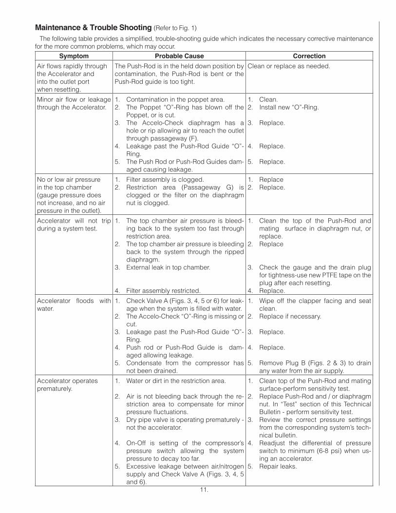
Maintenance & Trouble Shooting (Refer to Fig. 1)
The following table provides a simplified, trouble-shooting guide which indicates the necessary corrective maintenance for the more common problems, which may occur.
Symptom Probable Cause Correction
Air flows rapidly through the Accelerator and into the outlet port when resetting.
The Push-Rod is in the held down position by contamination, the Push-Rod is bent or the Push-Rod guide is too tight.
Clean or replace as needed.
Minor air flow or leakage through the Accelerator.
1. Contamination in the poppet area.2. The Poppet “O”-Ring has blown off the
Poppet, or is cut. 3. The Accelo-Check diaphragm has a
hole or rip allowing air to reach the outlet through passageway (F).
4. Leakage past the Push-Rod Guide “O”-Ring.
5. The Push Rod or Push-Rod Guides dam-aged causing leakage.
1. Clean.2. Install new “O”-Ring.
3. Replace.
4. Replace.
5. Replace.
No or low air pressure in the top chamber (gauge pressure does not increase, and no air pressure in the outlet).
1. Filter assembly is clogged.2. Restriction area (Passageway G) is
clogged or the filter on the diaphragm nut is clogged.
1. Replace 2. Replace.
Accelerator will not trip during a system test.
1. The top chamber air pressure is bleed-ing back to the system too fast through restriction area.
2. The top chamber air pressure is bleeding back to the system through the ripped diaphragm.
3. External leak in top chamber.
4. Filter assembly restricted.
1. Clean the top of the Push-Rod and mating surface in diaphragm nut, or replace.
2. Replace
3. Check the gauge and the drain plug for tightness-use new PTFE tape on the plug after each resetting.
4. Replace.
Accelerator floods with water.
1. Check Valve A (Figs. 3, 4, 5 or 6) for leak-age when the system is filled with water.
2. The Accelo-Check “O”-Ring is missing or cut.
3. Leakage past the Push-Rod Guide “O”-Ring.
4. Push rod or Push-Rod Guide is dam-aged allowing leakage.
5. Condensate from the compressor has not been drained.
1. Wipe off the clapper facing and seat clean.
2. Replace if necessary.
3. Replace.
4. Replace.
5. Remove Plug B (Figs. 2 & 3) to drain any water from the air supply.
Accelerator operates prematurely.
1. Water or dirt in the restriction area.
2. Air is not bleeding back through the re-striction area to compensate for minor pressure fluctuations.
3. Dry pipe valve is operating prematurely - not the accelerator.
4. On-Off is setting of the compressor’s pressure switch allowing the system pressure to decay too far.
5. Excessive leakage between air/nitrogen supply and Check Valve A (Figs. 3, 4, 5 and 6).
1. Clean top of the Push-Rod and mating surface-perform sensitivity test.
2. Replace Push-Rod and / or diaphragm nut. In “Test” section of this Technical Bulletin - perform sensitivity test.
3. Review the correct pressure settings from the corresponding system’s tech-nical bulletin.
4. Readjust the differential of pressure switch to minimum (6-8 psi) when us-ing an accelerator.
5. Repair leaks.
The Reliable Automatic Sprinkler Co., Inc.(800) 431-1588 Sales Offices(800) 848-6051 Sales Fax(914) 829-2042 Corporate Officeswww.reliablesprinkler.com Internet Address
Manufactured byRecycled
Paper
Revision lines indicate updated or new data.
EG. Printed in U.S.A 07/13 P/N 9999970157
The equipment presented in this bulletin is to be installed in accordance with the latest published Standards of the National Fire Protection Association, Factory Mutual Research Corporation, or other similar organizations and also with the provisions of governmental codes or ordinances whenever applicable.
Products manufactured and distributed by Reliable have been protecting life and property for over 90 years, and are installed and serviced by the most highly qualified and reputable sprinkler contractors located throughout the United States, Canada and foreign countries.
• Automatic sprinklers
• Flush automatic sprinklers
• Recessed automatic sprinklers
• Concealed automatic sprinklers
• Adjustable automatic sprinklers
• Dry automatic sprinklers
• Intermediate level sprinklers
• Open sprinklers
• Spray nozzles
• Alarm valves
• Retarding chambers
• Dry pipe valves
• Accelerators for dry pipe valves
• Mechanical sprinkler alarms
• Electrical sprinkler alarm switches
• Water flow detectors
• Deluge valves
• Detector check valves
• Check valves
• Electrical system
• Sprinkler emergency cabinets
• Sprinkler wrenches
• Sprinkler escutcheons and guards
• Inspectors test connections
• Sight drains
• Ball drips and drum drips
• Control valve seals
• Air maintenance devices
• Air compressors
• Pressure gauges
• Identification signs
• Fire department connection
Reliable offers a wide selection of sprinkler components. Following are some of the many precision-made Reliable products that guard life and property from fire around the clock.
Reliable...For Complete Protection


![FAN CLOTH ORDER SCHOOL NAME: NAME: PHONE: ITEM …static.squarespace.com/static/51c322cfe4b032aad705...1 item per line on order form [reverse side of this page] Check the item for](https://img.pdfslide.net/doc/110x75/5f55b0dccc2e37791544b903/fan-cloth-order-school-name-name-phone-item-1-item-per-line-on-order-form.jpg)